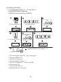
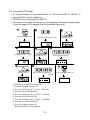
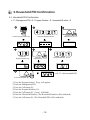
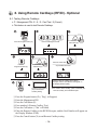
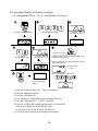
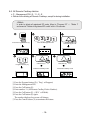
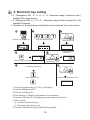
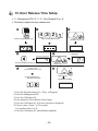
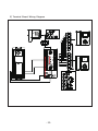
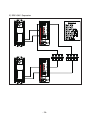
1
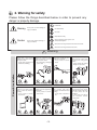
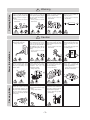
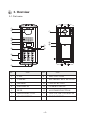
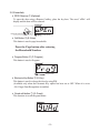
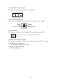
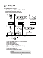
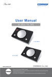
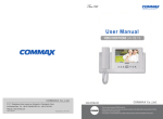
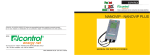
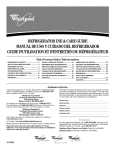
User Manual Lobby camera phone DRC-GAC/GAB - Feature - ● Covers all building with UPT cable. ● RF/ID (function optional) • • Thank Thank you you for for purchasing purchasing COMMAX COMMAX products. products. • • Please Please carefully carefully read read this this User’s User’sGuide Guide(in (inparticular, particular,precautions precautionsfor forsafety) safety)before beforeusing usingaaproduct productand andfollow follow instructions instructions to to use use aa product product exactly. exactly. • • The The company company isis not not responsible responsible for forany anysafety safetyaccidents accidentscaused causedby byabnormal abnormaloperation operationof ofthe theproduct. product. Table of Contents 1.Greeting . . . . . . . . . . . . . . . . . . . . . . . . . . . . . . . . . . . . . . . . . . . . . . . .1 2.Warning for safety . . . . . . . . . . . . . . . . . . . . . . . . . . . . . . . . . . . . . . . .2 3.Overview . . . . . . . . . . . . . . . . . . . . . . . . . . . . . . . . . . . . . . . . . . . . . . .4 4. PIN Types . . . . . . . . . . . . . . . . . . . . . . . . . . . . . . . . . . . . . . . . . . . . . .8 5. Setting PIN . . . . . . . . . . . . . . . . . . . . . . . . . . . . . . . . . . . . . . . . . . . . .9 6. Household PIN Confirmation . . . . . . . . . . . . . . . . . . . . . . . . . . . . . . .12 7. Configuring Serial Numbers in the Main Entrance Interphone . . . . . . .13 8. Using Remote Cardkeys . . . . . . . . . . . . . . . . . . . . . . . . . . . . . . . . . . .15 (RF/ID) - Optional 9. Electronic key setting . . . . . . . . . . . . . . . . . . . . . . . . . . . . . . . . . . . . . .20 10. Door Release Time Setup . . . . . . . . . . . . . . . . . . . . . . . . . . . . . . . . .21 11. Line call Setup . . . . . . . . . . . . . . . . . . . . . . . . . . . . . . . . . . . . . . . . . .23 12. Paging Signal Selection . . . . . . . . . . . . . . . . . . . . . . . . . . . . . . . . . . .23 13. The number of emitting chime setup . . . . . . . . . . . . . . . . . . . . . . . . .24 14. Video Out Impedance Adjustment . . . . . . . . . . . . . . . . . . . . . . . . . . .25 15. Input Household number . . . . . . . . . . . . . . . . . . . . . . . . . . . . . . . . . .26 16. Household Number Registration . . . . . . . . . . . . . . . . . . . . . . . . . . . .28 17. Paging the Household . . . . . . . . . . . . . . . . . . . . . . . . . . . . . . . . . . . .28 18. Door Release Using the Household PIN . . . . . . . . . . . . . . . . . . . . . .29 19. Door Release Using the Building (Management) PIN . . . . . . . . . . . .29 20. Appendix (Various Program Summaries) . . . . . . . . . . . . . . . . . . . . . .30 21. How to use lobby phone . . . . . . . . . . . . . . . . . . . . . . . . . . . . . . . . . . .31 22. Wiring Method . . . . . . . . . . . . . . . . . . . . . . . . . . . . . . . . . . . . . . . . . .32 22. Mscellaneous . . . . . . . . . . . . . . . . . . . . . . . . . . . . . . . . . . . . . . . . . . .36 23. Specifications . . . . . . . . . . . . . . . . . . . . . . . . . . . . . . . . . . . . . . . . . .36 1. Greetings Thank you for purchasing a Commax product. This product is a high tech Main Entrance interphone that supports electronic and remote (Optional) keys features. Please read this manual carefully and familiarize yourself with it before use. - 1- 2. Warning for safety Please follow the things described below in order to prevent any danger or property damage. Warning Caution Prohibition. It may cause a serious damage or injury if violated. No disassembly No touch Must follow strictly. Shows plugging out the power cord without an exception It may cause a minor damage or injury if violated. Shows the warning and caution for an electric shock. Shows the warning and caution for a fire. Power & Installation Warning Please don’t use several products at the same time on one power socket. ·It may cause a fire due to an abnormal overheating. Please don’t bend the power cable excessively or it may cause an electric shock. ·fire when using a damaged power cable. Please don’t handle the power cable with a wet hand. ·It may cause an electric shock. Please plug out the power cable from the socket when not using it for a long period of time. ·It may shorten the product lifespan or cause a fire. Please don’t install the product in the place where there is much oil, smoke or humidity. ·It may cause an electric shock or fire. Please don’t install the product with the lightening and thunder. ·It may cause an electric shock or fire. Please don’t use and connect this product with other products with different rated voltage ·It may cause a disorder or fire. When installing the product that generates heat, please install the product away from the wall (10cm) for the ventilation. ·It may cause a fire due to the increased internal temperature. - 2- Cleaning & Use Power & Installation Cleaning & Use Please don’t disassemble, repair or rebuild this product arbitrarily (please contact the service center if a repair is needed. ·It may cause an electric shock or fire. Warning If an abnormal sound, burning smell or smoke is coming out of the product, please plug out the power cable and contact a service center. ·It may cause an electric shock or fire. Please don’t insert any metallic or burnable materials into the ventilation hole. ·It may cause an electric shock or fire. Caution Please plug the power cable firmly into the inner end ·It may cause a fire. Please hold the plug tightly when unplugging the power cable (a part of the copper wire may be disconnected if the grabbing is only made on the cord when pulling out the cable). ·It may cause an electric shock or fire When connecting the power cables after cutting the cable, please install the product with power off ·It may cause an electric shock or fire Please be careful when using an AC circuit breaker since there is a possibility of an electric shock. Please check the use voltage and current for the DC-only products and use the appropriate rectifier. ·It may cause a fire. Please avoid direct rays of the sun or heating devices at a time of installation. ·It may cause a fire. When cleaning the product, please rub it with a soft and dry cloth after plugging out the power cable. (Please don’t use any chemical products such as wax, benzene, alcohol or cleanser.) Please don’t drop the product on the ground and don’t apply a shock . ·It may cause a failure. Please use the designated connection cable within the maximum calling distance designated for the product ·It may reduce the product performance. - 3- Please use only the designated batteries for the products of using DC power. ·It may cause an electric shock or fire. When installing the product, please fix it firmly while using the wall-mounting unit and screws. ·It may cause an injury from the falling object. Please don’t install the product on an unstable place or small support board. ·It may cause an injury if it falls down while in use. 3. Overview 3-1. Part name ① ② ⑫ ③ ④ ⑤ ⑦ ⑬ ⑭ ⑧ ⑥ ⑨ ⑩ ⑪ No FUN No FUN 1. C-MIC 8. INPUT BUTTON 2. CAMERA 9. ELETRONIC KEY BUTTON 3. SPEAKER 10. CANCEL BUTTON 4. FND DISPLAY 11. CAMERA ANGLE 5. RF-ID 12. AJUSTMENT BUTTON 6. PROGRAM BUTTON 13. TALK VOLUME CONTROLLER 7. GUARD BUTTON 14. RESET SWITCH - 4- 3-2 Essentials ✽ RF/ID Receiver ⑤ (Optional) To open the door using a Remote Cardkey, place the key here. The word‘oPEn’will display and the door will be released. Please the Card Here OPEN DOOR ✽ Call Button ⑧ (E: Enter) This button is used to page households. Press the Page button after entering the Household Number. ✽ Program Button ⑥ (P: Program ) This button is used to Program. Program Enter ✽ Electronic Key Button ⑪ (K: Key) This button is used to release the door by using PIN. (Available only when the Electronic Key option has been set as OFF. When it is set as ON, Finger Print Recognition is enabled) ✽ Guard callt button ⑦ (G: Guard) This function is to call the guard house - 5- ✽ Cancel Button ⑪ (X: Cancel) This button is used to cancel the current operation. ✽ Talk volume controller ⑬ Talk volume is adjustable by switching the controller to Low or High To Lower the Volume To Raise the Volume ✽ Reset Button ⑭ This button is used to reset the Building PIN or the Management PIN If the Management PIN can not be remembered, press the Reset button ✽ Change the message on FND To change the message on FND, press the Program button (P) for 5 seconds. 1) Displaying system version ⇨ 0101-9901 SLI DRC-GAC Ver.01 2) Displaying general message ⇨ hELLo hAPPy dAy - 6- ● Must Know Before Use! 1) Accessing All Features with the Program Button -When an error has been made as indicated by continuous beeps, please cancel and start again from the beginning. Beep-Beep-Beep (Error) Start again from the beginning 2) Forgotten PIN 2-1. Household PIN Use the Household PIN verification feature of 6-1 to retrieve the PIN. (Please inquire to the Guardhouse or the Management Office) 2-2. Building PIN Reenter using the Management PIN. 2-3. Management PIN Press the Reset button. Both the Building and the Management Building PINs are reset to default. 3) All Remote Cardkey Deletion of 8-3 is to be used only when the unit is being initially installed. 4) Configuration Mode Indications Configured features are displayed on the Display Window when the Main Entrance interphone is not in use. 0 1 0 1 - 9 9 0 S - L I DRC-GAC V e r 0 1 O p e n Door status Version No. Series Camera Impedance Serial Number Building Number - 7- 4. PIN Types 4-1. Management PIN - This PIN is for use by the person in charge of the Management Office. - By default, this PIN is set as 4321. - Management PIN shall be stated as “Management PIN” here below 4-2. Building PIN - This is the common PIN for each main entrance. - By default, this PIN is set as 1234. - Management PIN shall be stated as “Building PIN” here below 4-2. Household PIN - Each household has its own PIN. - By default, this PIN is set as 1234. - For convenience, hereafter household PIN. <Reference> ✽ P : Program ✽ K : Electronic Key ✽ Old PIN Default Management PIN: 4321 Default Building PIN: 1234 Default Household PIN: 1234 ✽ New PIN New PIN to be set by the user. - 8- ✽ E : Call 5. Setting PIN 5-1. Management PIN Setup ✽ P - Old Management PIN - E - 0 - E - New PIN -E ✽ Management PIN must be 4-digits long. ✽ 0000 will not be recognized as a valid PIN. Press the Program button (P). Press the Program Number 0. Press the Call button (E). Enter the old PIN 4321. Press the Call button (E). Enter the new PIN. ex)1470 Management PIN has been updated. Press the Call button (E). ① Press the Program button (P). ‘Prog’ ( will appear) ② Enter the old PIN 4321. ③ Press the Call button (E). ④ Press the Program Number 0. ⑤ Press the Call button (E). ‘PASS’ ( will blink) ⑥ Enter the new PIN. ⑦ Press the Call button (E). ⑧ Management PIN has been updated. <Note> Be sure to change managing password ahead of use - 9- 5-2. Building PIN Setup ✽ P - Old Management PIN - E - 1 - E - New PIN - E ✽ Building PIN must be 4-digits long. ✽ 0000 will not be recognized as a valid PIN. Press the Program button (P). Press the Program Number (1). Enter the old PIN 1234. Press the Call button (E). Press the Call button (E). Enter the new PIN. ex)2580 Building PIN has been updated. Press the Call button (E). ① Press the Program button (P).‘Prog’ ( will appear) ② Enter the old PIN 4321. ③ Press the Call button (E). ④ Press the Program Number 1.. ⑤ Press the Call button (E).‘PASS’ ( will blink) ⑥ Enter the new PIN. ⑦ Press the Call button (E). ⑧ Building PIN has been updated - 10 - 5-3. Household PIN Setup ✽ K - Program Number - E - Household Number - E - Old Household PIN - E - New PIN - P ✽ Household PIN must be 4-digits long. ✽ 0000 will not be recognized as a valid PIN. ✽ This method of Household PIN change may vary depending on household interphone types. (Types that support PIN changing from the household interphone) Electronic Key button (K). Household Number. ex) 101 Press the Call button (E). Press the Program Number (20). Press the Call button (E). Enter the old PIN. ex)1234 Enter the new Household PIN. ex)3690 ① Press the Electronic Key button (K). ② Press the Program Number 20. ③ Press the Call button (E).‘hono’ ( will blink) ④ Enter the Household Number. ⑤ Press the Call button (E).‘PASS’ ( will blink) ⑥ Enter the old Household PIN. ⑦ Press the Call button (E).‘PASS’ ( will blink) ⑧ Enter the new Household PIN ⑨ Press the Program button (P). Household PIN has been updated. - 11 - Press the Call button (E). Press the Program button (P). 6.Household PIN Confirmation 6-1. Household PIN Confirmation ✽ P - Management PIN - E - Program Number - E - Household Number - E Press the Program button (P). Press the Program Number (16). Enter the Management PIN. Press the Call button (E). Press the Call button (E). Household Number. ex) 101 ex)1 2 3 4 for household 101 Press the Call button (E). ① Press the Program button.‘Prog’ ( will appear) ② Enter the Management PIN. ③ Press the Call button (E). ④ Press the Program Number (16). ⑤ Press the Call button (E).‘hono’ ( will blink) ⑥ Enter the Household Number. (The Household Number will be indicated) ⑦ Press the Call button (E). (The Household PIN will be indicated) - 12 - 7.Configuring Serial Numbers in the Main Entrance Interphone ✽ P - Management PIN - E - 3 - E - Serial Number - E Press the Program button (P). Press the Program Number (3). Enter the Management PIN. Press the Call button (E). The Serial Number previously entered will be indicated Press the Call button (E). Enter the New Serial Number ex) No. 2 Serial Number has been updated. Press the Call button (E). ① Press the Program button (P).‘Prog’ ( will appear) ② Enter the Management PIN. ③ Press the Call button (E). ④ Press the Program Number (3) . ⑤ Press the Call button (E). (The Serial Number previously entered will be indicated) ⑥ Enter the new Serial Number. ⑦ Press the Call button Serial Number has been updated. - 13- 8. Using Remote Cardkeys (RF/ID) - Optional 8-1. Testing Remote Cardkeys ✽ P - Management PIN - E - 9 - E - Card Test - X (Cancel) ✽ This feature is used to test Remote Cardkeys. Press the Program button (P). Press the Program Number (9). Enter the Management PIN. Press the Call button (E). Press the Card Here Press the Call button (E). ex) Card Number 3579 Place the Remote Cardkey to the RF/ID Receptor, and the Card Number will appear on the Display Window (FND). Press the Cancel button (X) to end Remote Cardkey testing ✽To confirm others cardkey, place continuedly the Remote Cardkey to the RF/ID Recepter ① Press the Program button (P).‘Prog’ ( will appear) ② Enter the Management PIN. ③ Press the Call button (E). ④ Press number 9 (Remote Cardkey Test). ⑤ Press the Call button.‘Cdtt’ ( will blink) ⑥ Place the Remote Cardkey to the RF/ID Receptor, and the Card Number will appear on the Display Window (FND). ⑦ Press the Cancel button (X) to end Remote Cardkey testing. - 14- 8-2. Remote Cardkey Registration ✽ P - Management PIN - E - 10 - E - Card Registration - X (Cancel) Press the Program button (P). Press the Program Number (10). 4 3 2 1 Enter the Management PIN. Press the Call button (E). Press the Card Here Press the Call button (E). Place the Remote Cardkey to the RF/ID Receptor, and ‘Cdsv’ or ‘CdAL’ will appear Newly Registered Card Press the Cancel button (X) to end Remote Cardkey testing Previously Registered Card ✽To confirm others cardkey, place continuedly the Remote Cardkey to the RF/ID Recepter <Note> CdSv: Newly Registered Card (Successful registration is indicated by a beep) CdAl: Previously Registered Card (Rejected registration is indicated by two beeps) ✽ Up to 2048 Remote Cardkeys can be registered. (Without a computer connected) ✽ Please record registered Remote Cardkey’s serial number for future reference. CdFu : Exceeding card storage limit (If you didn't register a card, please delete all saved card referring to 8-5 chapter) <Caution> Do not turn off the products within ten seconds after registering RF cards. It might cause a problem in saving RF cards information. - 15- 8-3. Individual Deletion of Remote Cardkeys ✽ P - Management PIN - E - 12 - E - Card Deletion - X (Cancel) Press the Program button (P). Press the Program Number (12). 4 3 2 1 Enter Management PIN. Press the Call button (E). Press the Card Here 1. Place the Card on top of the RF/ID Receiver, and will delete Card Number Press the Call button (E). 2. Enter Card Number and press Call button, and will delete Card Number ex) Card Number 19919 ex) For Card Number 19919 delete Press the Cancel button (X) to terminate the feature ① Press the Program button (P).‘Prog’ ( will appear) ② Enter the Management PIN. ③ Press the Call button (E). ④ Press number 12 (Individual Remote Cardkey Deletion). ( will blink) ⑤ Press the Call button (E).‘CddE’ ⑥ Enter the 5-digit Card Number and press the Call button (E). (Check on the right side of the RF/ID Card) Or place the Card on top of the RF/ID Receiver. ⑦ Press the Cancel button (X) to terminate the feature - 16- 8-4. Confirming Remote Cardkey Registration ✽ P - Management PIN - E - 13 - E - Card Confirmation - X (Cancel) Press the Program button (P). Press the Program Number (13). 4 3 2 1 Enter the Management PIN. Press the Card Here 1. Place the Card on top of the RF/ID Receiver, and will confirm. Press the Call button (E). Confirm Card 2. Enter Card Number and press Call button, and will confirm Remote Cardkey Registration. ex) Card Number 19919 Press the Call button (E). ex) For Card Number 19919 Confirm No Confirm Card Press the Cancel button (X) to terminate the feature ① Press the Program button (P).‘Prog’ ( will appear) ② Enter the Management PIN. ③ Press the Call button (E). ④ Enter number 13 (Remote Cardkey Confirmation). ( will blink) ⑤ Press the Call button (E).‘CddE’ ⑥ Enter the 5-digit Card Number and press the Call button (E). (Check the right side of the RF/ID Card) Or place the Card on top of the RF/ID Receiver. ⑦ Press the Cancel button (X) to terminate the feature. - 17- 8-5. All Remote Cardkey deletion ✽ P - Management PIN - E - 11 - E - E ✽ Refrain from deleting all Remote Cardkeys, except for during installation. <Note> In order to delete all registered RF cards, Move to "Program 23" ⇒ "Mode 1" and execute "Delete all registered RF cards" with in 30 seconds. Press the Program button (P). Press the Program Number (11). 4 3 2 1 Press the Call button (E). Enter the Management PIN. Press the Call button (E). All Remote Cardkey mode Press the Call button (E). All Remote Cardkey mode ① Press the Program button (P).‘Prog’ ( will appear) ② Enter the Management PIN. ③ Press the Call button (E). ④ Enter number 11 (All Remote Cardkey Delete Number). ⑤ Press the Call button (E).‘dEL’ ( will blink) ⑥ Press the Call button (E) again. The number displayed on screen will change. ⑦ Press the Cancel button (X) to terminate the feature. - 18- 9. Electronic key setting ✽ P - Management PIN - E - 8 - E - 0 – E : Deactivate usage of electronic keys ( Available PIN number access) ✽ P - Management PIN - E - 8 - E - E - : Deactivate usage of electronic keys Door ( Not available PIN access) ✽ This feature is for deactivating or activating the use of electronic keys in door access . Press the Program button (P). Enter the Management PIN. Press the Call button (E). Previous selection is displayed Press the Program Number (4). Press the Call button (E). Deactivate electronic key Call button (E). Activate electronic key Completion of activating electronic key ① Press the Program button (P). (‘Prog’ will appear) ② Enter the Management PIN. ③ Press the Call button (E). ④ Enter number 8 ( Monitor setting number for surveillance). ⑤ Press the Call button (E). (Displaying previous setting on the screen) ⑥ Select a mode. (0 : Activate electronic key use) (1 : Deactivate electronic key use) ⑦ Press the Call button (E) again. (Modification updated) - 19- 10. Door Release Time Setup ✽ P - Management PIN - E - 4 - E - Door Release Time - E ✽ This feature adjusts the door release time. Press the Program button (P). 4 3 2 1 Enter the Management PIN. Press the Call button (E). The current capacity is displayed. Press the Call button (E). Press the Program Number (5). Choose a time. Use numbers from 1 to 25. Press the Call button (E). ex) Door Release time Selected 10 seconds Modification updated ① Press the Program button (P).‘Prog’ ( will appear) ② Enter the Management PIN ③ Press the Call button (E). ④ Press number 4 (Door Release Time Setup). ⑤ Press the Call button (E). (Previous selection is displayed) ⑥ Choose a time. (From 1 to 25 seconds) Use numbers from 1 to 25. ⑦ Press the Call button (E). (Modification updated) - 20- 11. Line Call Setup ✽ P - Management PIN - E - 21 - E - 0 - E : All calls ✽ P - Management PIN - E - 21 - E – 0103 - E : Line call ex) This function is for calling to specified line like from 1st house line to 3rd house line. . Press the Program button (P). Enter the Management) PIN. Press the Call button (E). Previous selection is displayed Press the Program Number (21). Press the Call button (E). Enter the Line.st Press the Call button (E). Ex ) Call the 1ST Line to 3 Line Modification updated ① Press the Program button (P).‘Prog’ ( will appear) ② Enter the Management PIN. ③ Press the Call button (E). ④ Press number 21 ⑤ Press the Call button (E). (Previous selection is displayed) ⑥ Choose a line you want to call ex) In case of calling to 1st house to 3rd house line, input “0103” ⑦ Press the Call button (E). (Modification updated) - 21- 12. Page Signal Selection ✽ P - Management PIN - E - 5 - E - 0 - E: Melody Tone ✽ P - Management PIN - E - 5 - E - 1 - E: Bell (Ringer) ✽ This feature sets the Recall tone heard when Households or the Guardhouse is paged from the Main Entrance. Press the Program button (P). 4 3 2 1 Enter the Building (Management) PIN. ex) Building PIN Press the Call button (E). The current capacity is displayed. Press the Call button (E). Press the Program Number (7). Input line 0: Melody Tone 1: BELL Tone(RINGER) Press the Call button (E). ① Press the Program button (P).‘Prog’ ( will appear) ② Enter the Building (Management) PIN. ③ Press the Call button (E). ④ Press number 5 (Page Signal Selection). ⑤ Press the Call button (E). (Previous selection is displayed) ⑥ Select a page signal. ✽ 0 : Melody Tone ✽ 1 : Bell (Ringer) ⑦ Press the Call button (E). (Page signal updated) - 22- 13. The number of emitting chime setup ✽ P - Management PIN - E - 7 - E - 0 - E: Constant call ✽ P - Management PIN - E - 7 - E - 1 - E: Call once ✽ This function is to set the call sound when make a call to household or guard station from the lobby. Press the Program button (P). 4 3 2 1 Enter the Building (Management) PIN. ex) Building PIN Press the Call button (E). The current capacity is displayed. Press the Call button (E). Press the Program Number (6). Choose a mode 0: Constant call 1: Call once Press the Call button (E). ex) Setting for calling once Completion of setup 1 ① Press the Program button (P).‘Prog’ ( will appear) ② Enter the Management PIN. ③ Press the Call button (E). ④ Press number 7 (Wiring Method Selection). ⑤ Press the Call button (E). (Previous selection is displayed) ⑥ Select a wiring method. ✽ 0 : 0 : Melody ✽ 1: Bell (Ringer) ⑦ Press the Call button (E). (Save new setting) - 23- 14. Video Out Impedance Adjustment ✽ P - Building (Management) PIN - E - 6 - E - 0 - E: Short Distance ✽ P - Building (Management) PIN - E - 6 - E - 1 - E: Long Distance ✽ By default, the unit is set for short distance. Do not change if possible. Press the Program button (P). 4 3 2 1 Enter the Management PIN. Press the Call button (E). The current capacity is displayed. Press the Program Number (8). Select the Impedance Press the Call button (E). 0: Short Distance 1: Long Distance Press the Call button (E). ex) Impedance Adjusted short distance Impedance selection updated ① Press the Program button (P).‘Prog’ ( will appear) ② Enter the Building (Management) PIN. ③ Press the Call button (E). ④ Press number 7 (Wiring Method Selection). ⑤ Press the Call button (E). (Previous selection is displayed) ⑥ Select a wiring method. ✽ 0 : 0 : Melody ✽ 1: Bell (Ringer) ⑦ Press the Call button (E). (Save new setting) - 24- 15. Input Household number ✽ P - Management PIN - E - 15 - E - Household Number - E-Multi Sub number - E ✽ This function is for inputting household number with lobby phone in case of a guard station unit is not installed 4 3 2 1 Press the Program button (P). Press the Call button (E). Enter the Management PIN. Household PIN Entry Mode Press the Program Number (15). Press the Call button (E). Lift up the receiver from the Household and press the Guard button to page the Main Entrance Interphone, where the Household Number will be displayed. (Then, the displayed number must be changed for it is the default number from the factory.) ex) Entering as first 1234 Enter the Household number and press the Page button (E). ex) Entering as Unit 101 Press the Call button (E). Enter the Multi Sub number and press the Page button (E). ex) Entering as Master Press the Call button (E). Follow the same procedure to enter other Households. Press the Cancel button (X) to end. - 25- <Multi sub number> ✽ What is Multi sub number? In case that one household have more than one unit, assigned number to identify every unit for proper communication. ✽ Master assigned as “O” ✽ Sub Serial Numbers are from 1 to 9. ✽ Maximum 10 videophones can be installed in a household, and their serial numbers must not overlap. ✽ Assign sub number from 1 to 9 order. ✽ A Master must exist among numerous videophones. If only one videophone exists, that unit shall be registered as the Master. ① Press the Program button (P). (‘Prog’ will appear) ② Enter the Management PIN. ③ Press the Page button (E). ④ Enter number 15 (Household Interphone Diagnosis). ⑤ Press the Page button (E). (‘idCh’ will appear) ⑥ Call to guard station from household ⑦ The Household’s status is shown on the display window (FND). ⑧ Household Number, then press the Page button (E). (‘sub’ will appear) ⑨ Input Multi sub number, then press the Call button (E). ⑩ To check other Households, repeat steps 6 ~ 9. Press the Cancel button (X) to terminate the feature. - 26- 16. Paging the Household Press the page button. A paging tone will sound. Enter theHousehold Number. ex) unit 101 Press the Call button (E). Wait for a reply 17. Paging the Guardhouse Press the Guard button. Press the Page button. A paging tone will sound. Press the Call button (E). Wait for a reply - 27- 18. Door Release Using the Household PIN ✽ Household Number - K - Household PIN - E Enter the Household Number. Press the Electronic key button. Enter the Household PIN. Press the Page button. ex) To open the door of unit 101 Press the Call button (E). 19. Door Release Using the Building (Management) PIN ✽ O - K - Building (Management) PIN - E Press the Guard button. Press the Electronic key button. Enter the Building or the Management PIN. Press the Page button. Press the Call button (E). - 28- 20. Appendix (Various Program Summaries) ✽ Various PIN Programs 1. P - Old Management PIN - E - 0 - E - New PIN- E: Management PIN Change 2. P- Old Management PIN -E -1 - E - New PIN - E: Building PIN Change 3. K - 20 - E - Household Number - E - Old Household PIN - E - New PIN - P: Household PIN Change 4. P - Management PIN - E - 16 - E - Household Number - E: Household PIN Confirmation ✽ Configuring Building and Serial Numbers from the Main Entrance Interphone 1. P - Management PIN - E - 2 - E - Building Number - E: Building Number Setup 2. P - Management PIN - E - 3 - E - Serial Number - E: Serial Number Setup ✽ Remote Cardkey Programs 1. P - Management PIN - E - 9 - E: Remote Cardkey Test 2. P - Management PIN - E - 10 - E: Remote Cardkey Registration 3. P - Management PIN - E - 11 - E: All Remote Cardkey Delete (Household PIN Delete) 4. P - Management PIN - E - 12 - E: Individual Cardkey Delete 5. P - Management PIN - E - 13 - E: Remote Cardkey Confirmation ✽ Door Release Using Various PINs 1.GP - KP - Building (Management) PINP - E: Door release using Building (Management) PIN 2.Household NumberP - KP - Household PINP - E: Door release using Household PIN ✽ Other Feature Setup Methods 1.P - Management PIN - E - 4 - E: Surveillance Monitor Setup 2.P - Management PIN - E - 5 - E: Door Release Time Setup 3.P - Management PIN - E - 6 - E: Wiring Method Selection 4.P - Management PIN - E - 15 - E: Household Number Registration - 29- 21. How to use lobby phone. ✽ Calling to household from lobby phone ✽ Household number – E Press the household number Press the Call button. ex)In case of household 101 Emit call sounds ✽ Opening door with household PIN ✽ Household number – K – household PIN – E Press the household number ex) In case of household 101 Press the Household PIN Press the Key button Press the Call button - 30- 22. Wiring Method 1) Lobby camera phone(DRC-GAC/GAB) - 31- 2) System Schematic - 32- 3) Terminal Board Wiring Diagram - 33- 3) DRC-GAC Expansion - 34- 23. Miscellaneous ※ Please carefully read this User’s Guide before calling service man After checking the entire check list, please contact customer service center. We will do our best to make you satisfy with our services. 24. Specifications Installation Method Model Name Transmission System Power source Power consumption Conversation Lens Frequency Camera angle Minimum Illumination Distance Built-in light Temperature, Humidity Dimension Flush mounted type DRC-GAC / DRC-GAB Household (8 wires), Guard (4 wires) DC 12V/0.5A Standby: 200mA, Max: 500mA Hands-free B/W C.C.D 1/3", Color CCD 1/4" 15.735KHz, 60Hz / 15.625KHz, 50Hz Horizon: 68℃, Vertical: 55℃ 0.1Lux ( within 300mm from the camera) UPT cable: 300meter LED -10℃ ~ +50℃, 95% 124.6(W) X 317.2(H) X 59.7(D)mm RF-ID wireless module (optional) Model Frequency Frequency type Modulation system Communication system Operating distance DRC-GAC/RF 13.56Mhz Less than47.544mV/m at 10M A1D ASK One-way 30mm - 35- 513-11, Sangdaewon-dong, Jungwon-gu, Seongnam-si, Gyeonggi-do, Korea Int’l Business Dept. : Tel.; +82-31-7393-540~550 Fax.; +82-31-745-2133 Web site : www.commax.com Printed In Korea / 2010.09.103