1
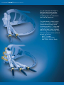
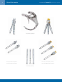
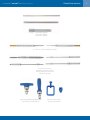
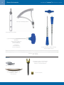
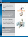
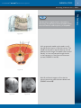
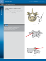
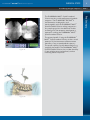
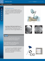
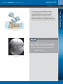
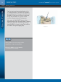
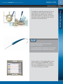
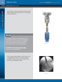
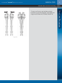
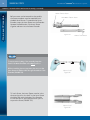
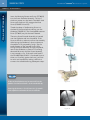
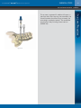
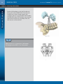
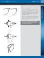
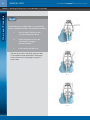
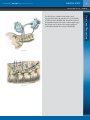
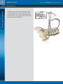
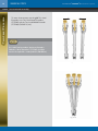
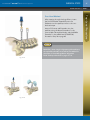
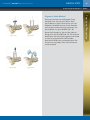
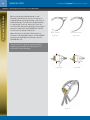
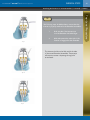
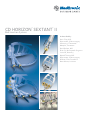
CD HORIZON SEXTANT II
®
®
Rod Insertion System
As described by:
Kevin Foley, M.D.
Department of Neurosurgery
University of Tennessee
Memphis, Tennessee
David Rouben, M.D.
River City Orthopaedic Surgeons
Louisville, Kentucky
Najeeb Thomas, M.D.
Department of Neurosurgery
Ocshner Clinic Foundation
New Orleans, Louisiana
CD HORIZON® SEXTANT ® II Rod Insertion System
The CD HORIZON® SEXTANT® II
Rod Insertion System provides
surgeons with next-generation
technology that will revolutionize
the future of spine care.
The global leader in today’s spine
market, we combine our lifestyle
friendly Minimal Access Spinal
Technologies (MAST™), integrated
image-guided products and neural
monitoring tools to help surgeons
shorten surgical and recovery time
and return patients more quickly to
normal, active lives.
• MAST™ Capable
• Navigation Compatible
• NIM-SPINE™ Monitor Ready
2
Table of Contents
Instruments
CD HORIZON® SEXTANT ® II Rod Insertion System
. . . . . . . . . . . . . . . . . . . . . . . . . . . . . . . . . . . . . . . . . . . . . . . . . . . . . . . . . . . . .
Instruments and Implants
. . . . . . . . . . . . . . . . . . . . . . . . . . . . . . . . . . . . . . . . . . . . . . . . . . . .
Preliminary Steps
Preoperative Planning and Set Up . . . . . . . . . . . . . . . . . . . . . . . . . . . . . . . . .
Positioning of Skin Incisions . . . . . . . . . . . . . . . . . . . . . . . . . . . . . . . . . . . . .
Considering Pedicle Anatomy . . . . . . . . . . . . . . . . . . . . . . . . . . . . . . . . . . . .
Considering Navigation Options–FLUORONAV® MAST™ Spinal Procedural Solution.
Surgical Technique Steps — One Level Procedure
Accessing the Pedicle . . . . . . . . . . . . . . . . . .
Guidewire Insertion . . . . . . . . . . . . . . . . . . . .
Dilating the Fascia . . . . . . . . . . . . . . . . . . . .
Pedicle Preparation . . . . . . . . . . . . . . . . . . . .
Screw Extender Assembly . . . . . . . . . . . . . . .
Screw Insertion . . . . . . . . . . . . . . . . . . . . . .
Second Screw Insertion . . . . . . . . . . . . . . . . .
Connecting the Extenders . . . . . . . . . . . . . . .
Attaching the Rod Inserter to Screw Extenders .
Passing the Trocar . . . . . . . . . . . . . . . . . . . .
Measuring the Rod . . . . . . . . . . . . . . . . . . . .
Passing the Rod . . . . . . . . . . . . . . . . . . . . . .
Set Screw Insertion and Final Break-off . . . . . .
Removing Assembly . . . . . . . . . . . . . . . . . . .
Closure . . . . . . . . . . . . . . . . . . . . . . . . . . . .
6
8
9
10
. 11
. . . . . . . . . . .
. . . . . . . . . . .
. . . . . . . . . .
. . . . . . . . . .
. . . . . . . . . . . . . . . . . . . . . . . . . . . . . . . . .
12
13
14
15
17
20
21
22
23
25
26
27
28
31
32
. . . . . . . . . . . . . . . . . . . . . . . . . . . . . . . . . . .
34
. . . . . . . . . . . . . . . . . . . . . . . . . . . . . . . . . . .
. . . . . . . . . . . . . . . . . . . . . . . . . . . . . . . . . . .
36
37
39
40
42
. . . . . . . . . . . . . . . . . . . . . . . . . . . . . . . . . . . . . . . . . . . . . . . . . . . . .
43
Surgical Technique Steps — Two Level Procedure
Accessing the Pedicle . . . . . . . . . . . . . . . .
Freehand Method
Alignment Guide Method
Screw Extender Assembly . . . . . . . . . . . . .
Screw Insertion . . . . . . . . . . . . . . . . . . . .
Connecting Extenders . . . . . . . . . . . . . . . .
Attaching Rod Inserter to Screw Extenders . .
Passing the Rod . . . . . . . . . . . . . . . . . . . .
Important Information
4
. . . . . . . . . . . . . . . . . . . . . . . . . . . . . . . . .
. . . . . . . . . . . . . . . . . . . . . . . . . . . . . . . . .
. . . . . . . . . . . . . . . . . . . . . . . . . . . . . . . . .
. . . . . . . . . . . . . . . . . . . . . . . . . . . . . . . . .
. . . . . . . . . . . . . . . . . . . . . . . . . . . . . . . . .
. . . . . . . . . . . . . . . . . . . . . . . . . . . . . . . . .
. . . . . . . . . . . . . . . . . . . . . . . . . . . . . . . . .
. . . . . . . . . . . . . . . . . . . . . . . . . . . . . . . . .
. . . . . . . . . . . . . . . . . . . . . . . . . . . . . . . . .
. . . . . . . . . . . . . . . . . . . . . . . . . . . . . . . . .
. . . . . . . . . . . . . . . . . . . . . . . . . . . . . . . . .
. . . . . . . . . . . . . . . . . . . . . . . . . . . . . . . . .
. . . . . . . . . . . . . . . . . . . . . . . . . . . . . . . . .
. . . . . . . . . . . . . . . . . . . . . . . . . . . . . . . . .
. . . . . . . . . . . . . . . . . . . . . . . . . . . . . . . . . . .
. . . . . . . . . . . . . . . . . . . . . . . . . . . . . . . . . . .
. . . . . . . . . . . . . . . . . . . . . . . . . . . . . . . . . . .
CD HORIZON® SEXTANT ® II
R O D I N S E RT I O N S Y S T E M
INSTRUMENTS/
IMPLANTS
4
General Instruments
CD HORIZON® SEXTANT ® II Rod Insertion System
CD-HORIZON® SEXTANT® II
Rod Inserter (7575300)
Two-Level Outer Extender (7575301)
Two-Level Middle Extender (7575302)
One-Level Extender A (7575303)
One-Level Extender B (7575304)
Inner Sleeves (7575305)
General Instruments
CD HORIZON® SEXTANT ® II Rod Insertion System
5.6mm Dilator (9560420)
9.3mm Dilator (9560421)
Sextant Dilator (8675422)
4.5, 5.5, 6.5, 7.5mm taps
4.5 – 5.5mm, 5.5 – 6.5mm Self-drilling, tapered taps
Bonescrew Driver (7570021)
Ball-end Bonescrew Driver (7570022)
Retaining Bonescrew Drive (7570023)
T27 Removal (7570088)
Quick-Connect Ratcheting Handle (9339082)
Q/C Ratcheting T-Handle (7579000)
Radiolucent Clamp (7575307)
Alignment Guide (7575306)
5
6
General Instruments
CD HORIZON® SEXTANT ® II Rod Insertion System
Stationary Rod Template (7575311)
Rod Template Pointer (7575312)
PAK Needle
1 Bevel, 1 Trocar Tip (8670009)
2 Bevel Tips (8670010)
2 Trocar Tips (8670015)
X-PAK Needle
2 Bevel Tip (8670210)
2 Trocar Tips (8670215)
Set Screw Retaining Compressors (7570095)
Break Off Handle (7570090)
Guidewires: Sharp 8670001
Blunt 8670002
Implants
CD HORIZON® LEGACY™ Cannulated Screws
Standard Configurations 5.5, 6.5, 7.5mm
available in 4.5 and 8.5mm diameters
Rod Trocar Tip (7570030)
5.5mm CD-HORIZON® SEXTANT® Rod
available in 30 – 130mm,
5mm increments
Set Screw (7570955)
CD HORIZON® SEXTANT ® II
R O D I N S E RT I O N S Y S T E M
ONE-LEVEL
SURGICAL STEPS
8
SURGICAL STEPS
CD HORIZON® SEXTANT ® II Rod Insertion System
Preliminary
STEP 1 | Preoperative Planning And Set Up
Preoperative planning can be useful in determining
the proper starting point and screw trajectory.
An axial view demonstrates the distance lateral
to the pedicle initially taken through the skin
(FIGURE 1).
TLIF Trajectory
4.0 – 4.5cm
Pedicle Screw
3.0 – 3.5cm
PLIF Trajectory
3.0 – 4.0cm
Discectomy
1.0 – 1.5cm
TIP
The starting point is rarely directly over the pedicle.
Some tables have pedestals that make it difficult to
get a true AP view of the pedicles, especially at the
S1 level. While adjustments in patient positioning
can be made, tables that limit good AP fluoro
should generally be avoided. A longer prep area
is also necessary for intraoperative flexibility.
Figure 1
When using the CD HORIZON® SEXTANT® II
Rod Insertion System, the patient should be
positioned prone, lying flat on the table. Either a
radiolucent frame or chest rolls may be used,
but a knee to chest position should be avoided.
Verify that adequate fluoroscopic images of the
pedicles can be obtained in both an AP and lateral
view before proceeding (FIGURE 2). To adequately
view the S1 pedicle, a Ferguson view presents the
best image.
TIP
Figure 2
On AP fluoro, the spinous processes should
lie midway between both pedicles.
On AP fluoro, the endplates are not
rounded and should be linear.
SURGICAL STEPS
CD HORIZON® SEXTANT ® II Rod Insertion System
9
Positioning of Skin Incisions | STEP 2
The skin incision is slightly lateral to the pedicle on
fluoroscopy. This will help to ensure the needle follows
the normal lateral to medial trajectory of the pedicle.
Figure 3A
A 22-gauge spinal needle may be used to verify
the appropriate location of the skin incisions. The
needle is positioned on the skin directly over the
pedicle on an AP image. The needle is then moved
laterally 1 to 2cm and inserted through the skin
to the intersection of the facet and transverse
process (FIGURES 3A and 3B).
Figure 3B
Both AP and lateral images confirm that the
appropriate starting place has been determined
(FIGURES 4A and 4B).
Figure 4A
Figure 4B
Preliminary
TIP
10
SURGICAL STEPS
CD HORIZON® SEXTANT ® II Rod Insertion System
Preliminary
STEP 3 | Considering Pedicle Anatomy
Consider the pedicle as roughly a cylindrical
structure.
As the pedicle is traversed, the trajectory should
allow the needle or screw to remain lateral to the
medial pedicle wall (FIGURE 5).
TIP
Figure 5
The ideal starting point is at the intersection
of the facet and the transverse process
(the lateral edge of the cylinder).
Figure 6A
Figure 6B
CD HORIZON® SEXTANT ® II Rod Insertion System
SURGICAL STEPS
11
Considering Navigation Options | STEP 4
Figure 7A
Figure 7B
The primary benefit of using the FLUORONAV®
MAST™ Spinal Procedural Solution is that a virtual
extension of the instruments will demonstrate
the safety of any proposed pedicle trajectory.
The proper trajectory can be determined prior to
navigating the pedicle. The FLUORONAV® MAST™
Spinal Procedural Solution also provides the ability
to see multiple views simultaneously without
increasing radiation exposure.
Preliminary
The FLUORONAV® MAST™ Spinal Procedural
Solution can also provide assistance with pedicle
navigation. The CD HORIZON® SEXTANT® II
instrumentation is designed to work
interchangeably with the FLUORONAV® MAST™
Spinal Procedural Solution making integration a
very simple proposition. An additional module
containing all of the necessary attachments is
required for utilizing the FLUORONAV® MAST™
Spinal Procedural Solution.
12
SURGICAL STEPS
CD HORIZON® SEXTANT ® II Rod Insertion System
One-Level Procedure
STEP 5 | Accessing the Pedicle
PAK Needle Insertion
A PAK (Pedicle Access Kit) Needle is used to
gain access to the pedicle. After placing the PAK
needle at the intersection of the facet and the
transverse process, the needle is advanced
(FIGURE 8).
Figure 8
An AP image should show the needle tip at the
lateral margin of the pedicle initially. As the
needle advances towards the base of the pedicle,
on the lateral image, it should approach the
pedicle center on the AP image. (FIGURE 9A – B)
Figure 9A
TIP
The PAK needle should be advanced across the
junction of the pedicle and the vertebral body so
to allow easier placement of the Guidewire.
Care should be taken so the needle is not too
medial. This avoids breaching the medial wall
when tapping or inserting the Screw.
For neuromonitoring, a NIM-SPINE™ PAK Needle
may be used to access the pedicle. Triggered
EMG monitoring can be performed during
advancement of the needle into the pedicle to
ensure proper placement.
Figure 9B
SURGICAL STEPS
CD HORIZON® SEXTANT ® II Rod Insertion System
13
Guidewire Insertion | STEP 6
Figure 10
TIP
“I recommend placing the Guidewire 60 – 70% of the
VB for a ‘safe zone’ of bony anatomy during pedicle
preparation and screw insertion. This tactic allows
for space if the Guidewire advances inadvertently.”
— Najeeb Thomas. M.D.
Figure 11
One-Level Procedure
The inner stylet of the needle is removed to
allow the Guidewire to be inserted into the
pedicle (FIGURES 10 and 11). Be extremely
careful with regard to the position of the
Guidewire. Unintentional advancement of the
wire can potentially be very dangerous. Once the
Guidewire is inserted, the needle may be removed.
14
SURGICAL STEPS
CD HORIZON® SEXTANT ® II Rod Insertion System
One-Level Procedure
STEP 7 | Dilating the Fascia
The fascia and muscle must be dilated to allow
for screw placement. Three Dilators are used to
gently make a path of the appropriate dimension
(FIGURE 12). The first two Dilators are removed,
leaving the third Dilator to serve as a tissue
protection sleeve during the Tapping step.
When using the NIM-SPINE™ System, a blue
disposable large Dilator should be used for dilating
and tapping purposes. After dilating, the large
disposable Dilator remains in place and serves as
an insulator during the Tapping step.
TIP
Incise the skin to allow for dilation of the
Large Dilator — approximately 15mm.
Dilators should dock on bony anatomy
to minimize tissue creepage.
Figure 12
SURGICAL STEPS
CD HORIZON® SEXTANT ® II Rod Insertion System
15
Pedicle Preparation | STEP 8
Figure 13
TIP
Use the Self Drilling Tap option if particularly
hard bone is encountered.
If using the NIM-SPINE™ System during this procedure,
the Large Insulated Dilator (8675424) must be used.
Further evaluation of the tapped pedicle can be
performed by using the NIM-SPINE™ System
Stim-controlled Ball Tip Probe to stimulate the
Tap. Free-running EMG will monitor any nerve
root irritation during this procedure.
One-Level Procedure
The pedicle is prepared by placing the Tap over
the Guidewire and through the third dilation
sleeve (Figure 13). In dense bone, where the
Screw may be difficult to advance, ensure that
the pedicle is fully prepared by using a Tap the
same size as the inserted Screw.
16
SURGICAL STEPS
CD HORIZON® SEXTANT ® II Rod Insertion System
One-Level Procedure
STEP 8 | Pedicle Preparation (cont.)
Screw length can be estimated by referencing the
depth marks on the Tap with the rim of the large
Dilator (FIGURE 14).
TIP
If you tap beyond the tip of the Guidewire, bone
within the end of the Tap may cause the Guidewire
to pull out as you remove the Tap. To avoid this,
advance the Guidewire through the Tap before
you remove the Tap from the vertebral body.
Figure 14
If the Guidewire becomes bent, place a PAK
Cannula over the bent Guidewire then replace
it with a new (straight) Guidewire.
Fluoroscopy should be used to verify the position
of the Guidewire and the Tap during this step
(FIGURE 15). After tapping, remove the Dilator
but leave the Guidewire in place.
Figure 15
CD HORIZON® SEXTANT ® II Rod Insertion System
SURGICAL STEPS
17
Extender Sleeve and Screw Assembly | STEP 9
Figure 16
One-Level Procedure
To insert two Screws, use the silver one level
Extenders: Single Level Extender A (7575303) and
Single Level Extender B (7575304) (FIGURE 16).
18
SURGICAL STEPS
CD HORIZON® SEXTANT ® II Rod Insertion System
STEP 10 | Extender Sleeve And Screw Assembly (continued)
One-Level Procedure
HEAD of Outer Sleeve
Before a screw can be inserted into the pedicle,
the Screw extenders must be assembled with
the Multi-Axial Screws. To assemble the Screw
Extender, insert the Inner Sleeve into the Extender.
Squeeze the flexible tabs of the Inner Sleeve
together and insert into the Outer Extender.
BUTTONS of Outer Sleeve
Figure 17A
TIP
To ensure easier loading of the assembly, keep the
head of the Outer Extender in the Open position.
While assembling these components, the arrow on the
Inner Sleeve should be visible through the window of the
Extender (FIGURE 17B).
Open to load
Figure 17B
To load a Screw, the Inner Sleeve must be in the
downward position: the shelf on the Inner Sleeve
should be flush with the ledge of the Extender
so that the tabs of the Inner Sleeve are open to
capture the Screw (FIGURE 17C).
Open to load
Figure 17C
TABS of Inner Sleeve
SURGICAL STEPS
CD HORIZON® SEXTANT ® II Rod Insertion System
19
Extender Sleeve And Screw Assembly (continued) | STEP 11
Open to load
Figure 18A
Figure 18B
Closed and secure
Figure 18C
Once the Screw is seated in the tabs, push the
Screw and Inner Sleeve into the Extender. Push the
head of the Outer Extender down and push the
Inner Sleeve with the screw into the Extender to
lock the assembly (FIGURES 18B – C). To verify the
assembly is connected properly, pull on the Screw.
To change Screw sizes once the Extenders have
been assembled, reverse the assembly steps by
pushing the buttons on the top of the Extender
and pull the head up. The Inner Sleeve is now
unlocked and can slide down to open the tabs.
TIP
Grip the shaft of the Extender Assembly to keep
the Inner Sleeve in the lowest position so the tabs
remain open.
One-Level Procedure
With the distal tabs of the Inner Sleeve in the
open position, place the Screw into the Inner
Sleeves (FIGURE 18A).
20
SURGICAL STEPS
CD HORIZON® SEXTANT ® II Rod Insertion System
One-Level Procedure
STEP 12 | Screw Insertion
Insert the Retaining Bonescrew Driver (7570023)
into the Screw Extender Assembly. The tip of
the driver passes into the head of the Multi-Axial
Screw until the driver fully engages the Bone
Screw (FIGURES 22 and 23).
Thread the sleeve of the Retaining Driver into
the head of the Screw before inserting over the
Guidewire (FIGURE 23). The Cannulated Bonescrew
Driver (7570021) may also be used if desired.
The entire Screw Extender Assembly is inserted
over the Guidewire and into the pedicle. If the
Screw is difficult to advance, remove the assembly
while leaving the Guidewire in place, and ensure
the pedicle is fully prepared by using a Tap the
same diameter as the inserted Screw. After
driving the Screw Assembly through the pedicle,
remove the Guidewire to prevent it from being
advanced. Be certain that the Screw Assembly
is not inserted too far. If the multi-axial head of
the CD HORIZON® LEGACY™ Cannulated Screw is
driven too forcefully against the bone, it will lose
its multi-axial capabilities, making it difficult to
connect the assemblies during subsequent steps.
TIP
If desired, the Guidewire may be removed from the
pedicle once the Bone Screw is in the vertebral body.
Figure 22
Inserting the Screw too far will cause it to lose multiaxial capabilities and make rod insertion difficult.
Figure 23
CD HORIZON® SEXTANT ® II Rod Insertion System
SURGICAL STEPS
21
Second Screw Insertion | STEP 13
Figure 24
One-Level Procedure
The process is repeated for additional Screws on
the same side. After inserting the assemblies, the
Screw Extenders should be at approximately the
same height outside the patient. The assemblies
should move freely following Screw insertion
(FIGURE 24).
22
SURGICAL STEPS
CD HORIZON® SEXTANT ® II Rod Insertion System
One-Level Procedure
STEP 14 | Connecting the Extenders
Rotate the Extenders so that the flat sides are
facing each other (FIGURE 25A). The male and
female parts are then mated together and
rotated so there is no gap between the Extenders
(FIGURE 25B). Once the Extenders are connected
and the flat surfaces are completely flush, the
Rod Inserter can be attached.
Figure 25A
TIP
Make sure there is no gap between the Extenders
by looking down the head or foot of the patient.
Figure 25B
CD HORIZON® SEXTANT ® II Rod Insertion System
SURGICAL STEPS
23
Attaching Rod Inserter To Screw Extenders | STEP 15
Closed and secure
Figure 26
Open the latch on the side of the Rod Inserter to
connect to the Extenders. Return to the LOCKED
position once Extenders fit securely in the arc.
(FIGURES 27A and B).
Please see the next page for important details
regarding the assembly of the Rod Inserters to
the Screw Extender Assembly.
Open and load
Figure 27A
Closed and secure
Figure 27B
One-Level Procedure
Open and load
Before connecting the Rod Inserter to the
Extenders, attach the Trocar tip into the tip of
the Rod Inserter by lifting the latch on the top of
the Rod Inserter. This will allow the Rod Inserter
to receive the Rod. Insert the Trocar tip into the
Collet and return the latch to the original position
to secure the tip (FIGURE 26). Pull on the Trocar
to ensure a secure fit.
24
SURGICAL STEPS
CD HORIZON® SEXTANT ® II Rod Insertion System
One-Level Procedure
STEP 15 | Attaching Rod Inserter To Screw Extenders (continued)
TIP
The following steps should be taken to ensure that the
Inserter is properly attached to the Extender Assemblies:
1.
Push one side of the Inserter arm
onto the Extender with thumb.
2.
Hold and squeeze the other side
of the Inserter to engage
the other Extender.
3.
Tip 1
Lock assembly with lever arm.
The inserter should now be flush with both sides
of the mated Extender Assemblies. These steps
will ensure accurate rod passage through the
screw heads.
Tip 2
Tip 3
CD HORIZON® SEXTANT ® II Rod Insertion System
SURGICAL STEPS
25
Passing The Trocar | STEP 15
Figure 29
Figure 30
One-Level Procedure
The Rod Trocar is used to help make a path
through the fascia and muscle down to the saddle
of the first Screw (FIGURE 29). A small skin incision
is required and then the Trocar is advanced through
the muscle until it hits the first screw saddle as
confirmed by lateral fluoroscopy (FIGURE 30).
26
SURGICAL STEPS
CD HORIZON® SEXTANT ® II Rod Insertion System
One-Level Procedure
STEP 17 | Measuring the Rod
To determine the appropriate Rod length, place
the Rod Templates into the cephalad and caudal
Screw Extenders. Place the Rod Template Pointer
toward the Stationary Rod Template to determine
the measurement (FIGURE 31).
Figure 31
SURGICAL STEPS
CD HORIZON® SEXTANT ® II Rod Insertion System
27
Passing the Rod | STEP 18
Closed and Secure
Figure 32
TIP
1.
Ensure that the Rod is fully seated in the Rod
Inserter by pushing the Rod firmly into the tip.
2.
Ensure alignment of the Rod with the
axis of the arc by sighting both the side
and top-down view for confirmation.
To confirm that the Rod is through all screw
heads, use any of the Bonescrew Drivers for
visual verification. Drop the Driver down the
shaft of the Extenders. If the black line on the
Driver is visible above the Extender, the Rod has
passed through the Screw (FIGURE 33A, 33B).
Confirmation can also be made with fluoroscopy.
Figure 33A
TIP
If there is difficulty passing the Rod through
the second Screw, the Rod Inserter may be
released from the Extenders for a “free-hand”
technique to pass the Rod. The Extenders must
be held together if this technique is used.
Figure 33B
One-Level Procedure
Open and Load
Replace the Trocar tip with the appropriately sized
Rod as determined by the Rod Template. Remove
the Trocar by lifting the Rod attachment lever to
open the Rod Collet. Insert the Rod and return the
lever to the locked position. Pass the Rod through
the screw heads so that the tapered tip of the
Rod is through the distal Screw (FIGURE 32).
28
SURGICAL STEPS
CD HORIZON® SEXTANT ® II Rod Insertion System
One-Level Procedure
STEP 19 | Set Screw Insertion And Final Break-Off
After verifying that the Rod is seated in all the
Screws, the Set Screws can be inserted with the
Set Screw Retaining Compressors (7570090).
The Compressors act as:
• Compressors or Distractors
• Self-retaining Break-Off Driver
Begin by loading the Set Screw on the tip of the
Compressor. Push the button on the Compressor
Handle (FIGURE 34). While pushing the button,
insert the Set Screw on the distal tip of the
Compressor (FIGURE 35A, B). Release the button
and tug on the Set Screw to ensure a secure
connection.
Figure 34
TIP
The button on the Compressor Handle should
be proud once the Set Screw is loaded.
Figure 35A
Figure 35B
SURGICAL STEPS
CD HORIZON® SEXTANT ® II Rod Insertion System
29
Set Screw Insertion And Final Break-Off (cont.) | STEP 19
Compression or Distraction:
Figure 36
Compression
To Compress or Distract: Provisionally tighten one
of the Set Screws. To compress, squeeze the two
Compressors together and lock down the final
Set Screw. (FIGURE 37) To distract, pull the two
handles apart and lock down the Set Screw.
(FIGURE 38).
TIP
The Break-Off Handle can also assist in
provisionally tightening the Set Screw.
Figure 37
Distraction
Figure 38
One-Level Procedure
Insert the Compressor and Set Screw assembly
down the Extender shaft and thread the Set
Screw into the saddle of the Screw to engage
the Rod (FIGURE 36).
30
SURGICAL STEPS
CD HORIZON® SEXTANT ® II Rod Insertion System
One-Level Procedure
STEP 19 | Set Screw Insertion And Final Break-Off (cont.)
The Rod Inserter Assembly serves as the
counter-torque device during final break-off.
The Break-off handle should be used for the final
break-off and to help provisionally tighten the Set
Screw. The Compressor retains the sheared-off
portion of the Set Screw (FIGURE 39).
TIP
Do not push the button on the top of the Compressor
handle until completely removed from the Extender
shaft as this will release the Set Screw prematurely.
Figure 39
SURGICAL STEPS
CD HORIZON® SEXTANT ® II Rod Insertion System
31
Removing Assembly | STEP 20
Open and Unload
Figure 40A
Remove the Extenders from the Screws by
depressing buttons on the Outer Extenders
and lifting the head of the Extender — remove
from the screw heads by pulling the Extender
assemblies out individually (FIGURE 41).
The final construct can be viewed with AP and
lateral fluoroscopy.
TIP
Gentle side-to-side rocking may assist
in removal of the Extenders.
Open and Unload
Figure 40B
Figure 41
One-Level Procedure
The Rod Inserter must be detached from the
Rod by reversing the steps of attachment. Lift
the lever to release the Rod and swing the arm
up to remove from the patient (FIGURE 40A). To
detach the Inserter from the Extenders, open the
Inserter via the side lever (FIGURE 40B).
32
SURGICAL STEPS
CD HORIZON® SEXTANT ® II Rod Insertion System
One-Level Procedure
STEP 21 | Closure
The entire process is repeated on the
contralateral side. Closure is accomplished with
a few interrupted stitches in the fascia,
a subcuticular skin suture, and Steri Strips
(FIGURE 42).
NOTE: Implant Explantation
The CD HORIZON® LEGACY™ Cannulated MultiAxial Screw, Set Screws, and Rods may be removed
by applying the T27 Removal Driver to the Set
Screw and turning counter-clockwise until the Set
Screw is removed. The CD HORIZON® LEGACY™
Cannulated Multi-Axial Pedicle Screws may be
removed by applying CD HORIZON® LEGACY™
Cannulated Retaining Bonescrew Driver from
the CD HORIZON® SEXTANT® II instrumentation
set to the Screw and turning counter-clockwise
until the Screw is removed from the pedicle.
Figure 42
CD HORIZON® SEXTANT ® II
R O D I N S E RT I O N S Y S T E M
TWO-LEVEL
SURGICAL STEPS
34
SURGICAL STEPS
CD HORIZON® SEXTANT ® II Rod Insertion System
Two-Level Procedure
Accessing the Pedicle
PAK Needle Insertion:
A PAK (Pedicle Access Kit) Needle is used to
gain access to the pedicle. After placing the PAK
needle at the intersection of the facet and the
transverse process, the needle maybe advanced
partially through the pedicle (FIGURE 43).
An AP image should show the needle tip at the
lateral margin of the pedicle initially. As the
needle advances towards the base of the pedicle,
on the lateral image, it should approach the
pedicle center on the AP image (FIGURE 44A – B).
Figure 43
TIP
The PAK needle should be advanced across the
junction of the pedicle and the vertebral body
to allow easier placement of the Guidewire.
Care should be taken so the needle is not too
medial. This avoids breaching the medial pedicle
wall when tapping or inserting the Screw.
Figure 44A
For neuromonitoring, a NIM-SPINE™ PAK Needle
may be used to access the pedicle. Triggered
EMG monitoring can be performed during
advancement of the needle into the pedicle
to ensure proper placement.
Figure 44B
SURGICAL STEPS
CD HORIZON® SEXTANT ® II Rod Insertion System
35
Accessing the Pedicle (continued) | STEP 5
Either oblique or AP fluoro should be used to insert
PAK Needles in all three pedicles so that the skin
insertion and pedicle insertion points are aligned in
the axial plane. Drawing a line on the skin prior to
insertion can facilitate this (FIGURE 45).
Insert the Guidewire as with single level
procedures by removing the PAK handle and inner
stylet. Remove the PAK cannula and dilate over
the Guidewire as with the one-level technique.
Figure 45
Alignment Guide Method:
Prepare pedicles at the most caudal
and cephalad levels in the same manner
described previously (FIGURE 46). Proceed
to page 38 for insertion of middle PAK
needle, Guidewire, and Screw Extenders.
Figure 46
Two-Level Procedure
Free-Hand Method:
36
SURGICAL STEPS
CD HORIZON® SEXTANT ® II Rod Insertion System
Two-Level Procedure
STEP 6 | Screw Extender Assembly
To insert three screws, use the gold Two-Level
Extenders: two Two-level Outer Extenders
(7575301) and the Two-Level Middle Extender
(7575302) (FIGURE 47, 48).
NOTE
For a multi-level procedure, the Screw Extenders
labeled as “Outer Extenders” (7575301) should be
used at the cephalad or caudal pedicles (FIGURE 48).
Figure 47
Figure 48
SURGICAL STEPS
CD HORIZON® SEXTANT ® II Rod Insertion System
37
Screw Insertion | STEP 7
After tapping through the large Dilator, insert
the Screw Extender Assemblies over the
Guidewire into the pedicle, similar to the onelevel technique.
Insert all 3 Screws and Extenders into the
pedicles, using the Outer Extenders for the
most caudal and cephalad levels, and the Middle
Extender for the middle level (FIGURE 50).
Proceed to Step 10 on page 40.
NOTE
Remember, when using the alignment guide technique,
the cephalad and caudal screw will be inserted before
placement of the middle guidewire. Alignment
Guide Technique described on pages 35 – 36.
Figure 49
Figure 50
Two-Level Procedure
Free-Hand Method:
38
SURGICAL STEPS
CD HORIZON® SEXTANT ® II Rod Insertion System
Two-Level Procedure
STEP 8 | Screw Insertion (continued)
Alignment Guide Method:
Insert Screws connected to the Outer Screw
Extenders at the most caudal and cephalad levels
(FIGURE 51A). Connect the Guide to the Outer
Screw Extenders and attach the Extender Clamp
(FIGURE 51B – C).
Insert the X-PAK Needle through the Guide and
target the middle pedicle using fluoroscopy, NIM,
or a navigation system. Advance the X-PAK to
the desired position, then insert the Guidewire
through the X-PAK into the pedicle (FIGURE 52).
Figure 51A
Figure 51B
Figure 51C
Figure 52
SURGICAL STEPS
CD HORIZON® SEXTANT ® II Rod Insertion System
39
Connecting the Extenders | STEP 9
Disconnect and remove the Extender Clamp
and Guide. Also remove the X-PAK to leave
the Guidewire in place. Dilate and tap over the
Guidewire. Assemble the Inner Screw Extender
with the appropriate size Screw and insert over
the Guidewire into place (FIGURE 53A – B).
Figure 53A
Figure 54A
Figure 53B
Figure 54B
Rotate the Extenders so that the flat sides are
facing each other (FIGURE 54A – B). The male and
female parts are then mated together and rotated
so there is no gap between the Extenders.
Once the Extenders are connected and the flat
surfaces are completely flush, the Rod Inserter
can be attached.
Two-Level Procedure
Alignment Guide Method:
40
SURGICAL STEPS
CD HORIZON® SEXTANT ® II Rod Insertion System
Two-Level Procedure
STEP 10 | Attaching Rod Inserter To Screw Extenders
Before connecting the Rod Inserter to the
Extenders, attach the Trocar tip into the tip of
the Rod Inserter by lifting the latch on the top of
the Rod Inserter. This will allow the Rod Inserter
to receive the Trocar tip. Insert the Trocar tip
into the Collet and return the latch to the original
position to secure the tip (FIGURE 55A – B). Pull
on the trocar to ensure a secure fit.
Open the latch on the side of the Inserter to
connect to the Extenders. Return to the LOCKED
position once Extenders fit securely in the arc.
(FIGURE 56A – B).
Open and load
Closed and secure
Figure 55A
Figure 55B
Please see the next page for important details
regarding the assembly of the Rod Inserter to
the Screw Extender Assembly.
Figure 56A
Figure 56B
Figure 57
SURGICAL STEPS
CD HORIZON® SEXTANT ® II Rod Insertion System
41
Attaching Rod Inserter To Screw Extenders (continued) | STEP 11
The following steps should be taken to ensure that the
Inserter is properly attached to the Extender Assemblies:
Tip 1
1.
Push one side of the Inserter arm
onto the Extender with index finger.
2.
Hold and squeeze the other side of the
Inserter to engage the other Extender.
The inserter should now be flush with both sides
of the mated Extender Assemblies. These steps
will ensure accurate rod passage through the
screw heads.
Tip 2
Tip 3
Two-Level Procedure
TIP
SURGICAL STEPS
42
CD HORIZON® SEXTANT ® II Rod Insertion System
Two-Level Procedure
STEP 12 | Passing the Rod
Once all three extenders have been inserted,
proceed with attaching the Rod Inserter as
indicated in the one-level procedural steps.
Replace the Trocar tip with the appropriately sized
Rod as determined by the Rod Template. Remove
the Trocar by lifting the Rod attachment lever to
open the Rod Collet. Insert the Rod and return the
lever to the locked position. Pass the Rod through
the screw heads so that the tapered tip of the
Rod is through the distal Screw (FIGURE 58).
TIP
1.
Ensure that the Rod is fully seated in the Rod
Inserter by pushing the Rod firmly into the tip.
2.
Ensure alignment of the Rod with the axis of the
To confirm that the Rod is through all screw
heads, use any of the Bonescrew Drivers for visual
verification. Drop the Driver down the shaft of
the Extenders. If the black line on the Driver is
visible above the Extender, the Rod has passed
through the Screw. Confirmation can also be
made with fluoroscopy.
TIP
If there is difficulty passing the Rod through
the second Screw, the Rod Inserter may be
released from the Extenders for a “free-hand”
technique to pass the Rod. The Extenders must
be held together if this technique is used.
Once the Rod has been passed, insert the Set
Screws as described on page 26 from the OneLevel Technique and follow subsequent stops to
complete the procedure.
Open and Load
Closed and Secure
Figure 58
CD HORIZON® SEXTANT ® II Rod Insertion System
Important Information on the CD HORIZON® Spinal System
PURPOSE:
The CD HORIZON® Spinal System is intended to help provide immobilization and stabilization of spinal segments as an adjunct to fusion of the thoracic, lumbar, and/or sacral spine.
DESCRIPTION:
The CD HORIZON® Spinal System consists of a variety of shapes and sizes of rods, hooks, screws,
CROSSLINK® Plates, staples and connecting components, as well as implant components from other
Medtronic Sofamor Danek spinal systems, which can be rigidly locked into a variety of configurations, with
each construct being tailor-made for the individual case.
Certain implant components from other Medtronic Sofamor Danek spinal systems can be used with the CD
HORIZON® Spinal System. These components include TSRH® rods, hooks, screws, plates, CROSSLINK®
plates, connectors, staples and washer, GDLH™ rods, hooks, connectors and CROSSLINK® bar and connectors; LIBERTY™ rods and screws; DYNALOK PLUS® and DYNALOK® CLASSIC bolts along with rod/bolt
connectors; and Sofamor Danek Multi-Axial rods and screws. Please note that certain components are specifically designed to connect to φ3.5mm, φ4.5mm, φ5.5mm rods or φ6.35mm rods, while other components
can connect to both φ5.5mm rods and φ6.35mm rods. Care should be taken so that the correct components
are used in the spinal construct.
CD HORIZON® hooks are intended for posterior use only. CD HORIZON® staples and CD HORIZON®
ECLIPSE® rods and associated screws are intended for anterior use only. However, for patients of smaller
stature, CD HORIZON® 4.5mm rods and associated components may be used posteriorly.
The CD HORIZON® Spinal System implant components are fabricated from medical grade stainless steel,
medical grade titanium, titanium alloy, medical grade cobalt-chromium-molybdenum alloy, or medical
grade PEEK OPTIMA-LT1. Certain CD HORIZON® Spinal System components may be coated with hydroxyapatite. No warranties express, or implied, are made. Implied warranties of merchantability and fitness
for a particular purpose or use are specifically excluded. See the MSD Catalog for further information
about warranties and limitations of liability
Never use stainless steel and titanium implant components in the same construct.
Medical grade titanium, titanium alloy and/or medical grade cobalt-chromium-molybdenum alloy may be
used together. Never use titanium, titanium alloy and/or medical grade cobalt-chromium-molybdenum
alloy with stainless steel in the same construct.
The CD HORIZON® Spinal System also includes anterior staples made of Shape Memory Alloy (Nitinol
– NiTi). Shape Memory Alloy is compatible with titanium, titanium alloy and cobalt-chromium-molybdenum alloy. Do not use with stainless steel.
PEEK OPTIMA-LT1 implants may be used with stainless steel, titanium or cobalt-chromium-molybdenum
alloy implants. CD HORIZON® PEEK Rods are not to be used with CROSSLINK® Plates.
To achieve best results, do not use any of the CD HORIZON® Spinal System implant components with components from any other system or manufacturer unless specifically allowed to do so in this or another Medtronic
Sofamor Danek document. As with all orthopaedic and neurosurgical implants, none of the CD HORIZON®
Spinal System components should ever be reused under any circumstances.
Indications:
The CD HORIZON® Spinal System is intended for posterior, non-cervical fixation for the following indications:
degenerative disc disease (defined as back pain of discogenic origin with degeneration of the disc confirmed
by history and radiographic studies); spondylolisthesis; trauma (i.e., fracture or dislocation); spinal stenosis;
curvatures (i.e., scoliosis, kyphosis and/or lordosis); tumor; pseudarthrosis; and/or failed previous fusion.
When used in a percutaneous, non-cervical, posterior approach with the SEXTANT™
instrumentation, the CD HORIZON® screws are intended for the following indications: degenerative disc
disease (defined as back pain of discogenic origin with degeneration of the disc confirmed by history and
radiographic studies); spondylolisthesis; trauma (i.e., fracture or dislocation); spinal stenosis; curvatures (i.e.,
scoliosis, kyphosis and/or lordosis); tumor; pseudoarthrosis; and/or failed previous fusion.
Except for hooks, when used as an anterolateral thoracic/lumbar system, CD HORIZON® components such
as ECLIPSE® components are intended for the following indications: (1) degenerative disc disease (as defined
by back pain of discogenic origin with degeneration of the disc confirmed by patient history and radiographic
studies), (2) spinal stenosis, (3) spondylolisthesis, (4) spinal deformities (i.e., scoliosis, kyphosis, and/or
lordosis), (5) fracture, (6) pseudarthrosis, (7) tumor resection, and/or (8) failed previous fusion.
The CD HORIZON® SPINOUS PROCESS Plate is posterior, non-pedicle supplemental fixation device, intended
for use in the non-cervical spine (T1 – S1). It is intended for plate fixation/attachment to spinous process for the
purpose of achieving supplemental fusion in the following conditions: degenerative disc disease — defined as
back pain of discogenic origin with degeneration of the disc confirmed by history and radiographic studies;
spondylolisthesis; trauma (i.e., fracture or dislocation); and/or tumor.
The CD HORIZON® LEGACY 3.5mm rod and associated components, when used as a pedicle screw
fixation system of the non-cervical posterior spine in skeletally mature patients, are indicated for one or
more of the following: (1) degenerative spondylolisthesis with objective evidence of neurologic impairment, (2) fracture, (3) dislocation, (4) scoliosis, (5) kyphosis, (6) spinal tumor, and/or (7) failed previous
fusion (pseudarthrosis).
In addition, when used as a pedicle screw fixation system, the CD HORIZON® LEGACY 3.5mm rod and
associated components, are indicated for skeletally mature patients: (a) having severe spondylolisthesis
(Grades 3 and 4) of the fifth lumbar-first sacral (L5 – S1) vertebral joint; (b) who are receiving fusions
using autogenous bone graft only; (c) who are having the device fixed or attached to the lumbar and
sacral spine (L3 and below); and (d) who are having the device removed after the development of a
solid fusion mass.
When used as a pedicle screw system in skeletally mature patients, the CD HORIZON® Spinal System
PEEK rods and associated components are intended to provided immobilization and stabilization of spinal
segments as an adjunct to fusion in the treatment of the following acute and chronic instabilities of the
thoracic, lumbar and sacral spine: (1) degenerative spondylolisthesis with objective evidence of neurologic
impairment, (2) kyphosis, and/or (3) failed previous fusion. Additionally, when used as a pedicle screw
device, the CD HORIZON® Spinal System PEEK rod constructs are indicated for use in patients who: (1) are
receiving fusion with autogenous graft only, (2) who are having the device attached to the lumbar or sacral
spine, and/or (3) who are having the device removed after the development of a solid fusion mass.
In order to achieve additional levels of fixation, the CD HORIZON® Spinal System rods may be connected to the VERTEX™ Reconstruction System with the VERTEX™ rod connector. Refer to the VERTEX™
Reconstruction System Package Insert for a list of the VERTEX™ indications of use.
CONTRAINDICATIONS:
Contraindications include, but are not limited to:
1.
2.
3.
4.
Active infectious process or significant risk of infection (immunocompromise).
Signs of local inflammation.
Fever or leukocytosis.
Morbid obesity.
5.
6.
7.
8.
Pregnancy.
Mental illness.
Grossly distorted anatomy caused by congenital abnormalities.
Any other medical or surgical condition which would preclude the potential benefit of spinal implant
surgery, such as the presence of congenital abnormalities, elevation of sedimentation rate unexplained
by other diseases, elevation of white blood count (WBC), or a marked left shift in the WBC differential
count.
9. Rapid joint disease, bone absorption, osteopenia, osteomalacia and/or osteoporosis.
10. Suspected or documented metal allergy or intolerance.
11. Any case not needing a bone graft and fusion.
12. Any case where the implant components selected for use would be too large or too small to achieve a
successful result.
13. Any patient having inadequate tissue coverage over the operative site or inadequate bone stock or quality.
14. Any patient in which implant utilization would interfere with anatomical structures or expected
physiological performance.
15. Any patient unwilling to follow postoperative instructions.
16. Any case not described in the indications.
POTENTIAL ADVERSE EVENTS:
All of the possible adverse events associated with spinal fusion surgery without instrumentation are possible.
With instrumentation, a listing of potential adverse events includes, but is not limited to:
1. Early or late loosening of any or all of the components.
2. Disassembly, bending, and/or breakage of any or all of the components.
3. Foreign body (allergic) reaction to implants, debris, corrosion products (from crevice, fretting, and/or
general corrosion), including metallosis, staining, tumor formation, and/or autoimmune disease.
4. Pressure on the skin from component parts in patients with inadequate tissue coverage over the implant
possibly causing skin penetration, irritation, fibrosis, neurosis, and/or pain. Bursitis. Tissue or nerve
damage caused by improper positioning and placement of implants or instruments.
5. Post-operative change in spinal curvature, loss of correction, height, and/or reduction.
6. Infection.
7. Dural tears, pseudomeningocele, fistula, persistent CSF leakage, meningitis.
8. Loss of neurological function (e.g., sensory and/or motor), including paralysis (complete or incomplete),
dysesthesias, hyperesthesia, anesthesia, paresthesia, appearance of radiculopathy, and/or the development or continuation of pain, numbness, neuroma, spasms, sensory loss, tingling sensation, and/or
visual deficits.
9. Cauda equina syndrome, neuropathy, neurological deficits (transient or permanent), paraplegia,
paraparesis, reflex deficits, irritation, arachnoiditis, and/or muscle loss.
10. Urinary retention or loss of bladder control or other types of urological system compromise.
11. Scar formation possibly causing neurological compromise or compression around nerves and/or pain.
12. Fracture, microfracture, resorption, damage, or penetration of any spinal bone (including the sacrum,
pedicles, and/or vertebral body) and/or bone graft or bone graft harvest site at, above, and/or below the
level of surgery. Retropulsed graft.
13. Herniated nucleus pulposus, disc disruption or degeneration at, above, or below the level of surgery.
14. Non-union (or pseudarthrosis). Delayed union. Mal-union.
15. Cessation of any potential growth of the operated portion of the spine.
16. Loss of or increase in spinal mobility or function.
17. Inability to perform the activities of daily living.
18. Bone loss or decrease in bone density, possibly caused by stresses shielding.
19. Graft donor site complications including pain, fracture, or wound healing problems.
20. Ileus, gastritis, bowel obstruction or loss of bowel control or other types of gastrointestinal system
compromise.
21. Hemorrhage, hematoma, occlusion, seroma, edema, hypertension, embolism, stroke, excessive
bleeding, phlebitis, wound necrosis, wound dehiscence, damage to blood vessels, or other types of
cardiovascular system compromise.
22. Reproductive system compromise, including sterility, loss of consortium, and sexual dysfunction.
23. Development of respiratory problems, e.g. pulmonary embolism, atelectasis, bronchitis, pneumonia, etc.
24. Change in mental status.
25. Death.
Note: Additional surgery may be necessary to correct some of these potential adverse events.
WARNING:
The safety and effectiveness of pedicle screw spinal systems have been established only for spinal conditions
with significant mechanical instability or deformity requiring fusion with instrumentation. These conditions are
significant mechanical instability or deformity of the thoracic, lumbar, and sacral spine secondary to degenerative spondylolisthesis with objective evidence of neurologic impairment, fracture, dislocation, scoliosis,
kyphosis, spinal tumor, and failed previous fusion (pseudarthrosis). The safety and effectiveness of this device
for any other conditions are unknown. The implants are not prostheses.
In the absence of fusion, the instrumentation and/or one or more of its components can be expected to pull
out, bend or fracture as a result of exposure to every day mechanical stresses.
PRECAUTION:
The implantation of pedicle screw spinal systems should be performed only by experienced spinal surgeons
with specific training in the use of this pedicle screw spinal system because this is a technically demanding
procedure presenting a risk of serious injury to the patient.
A successful result is not always achieved in every surgical case. This fact is especially true in spinal surgery
where many extenuating circumstances may compromise the results. This device system is not intended to
be the sole means of spinal support. Use of this product without a bone graft or in cases that develop into a
non-union will not be successful. No spinal implant can withstand body loads without the support of bone. In
this event, bending, loosening, disassembly and/or breakage of the device(s) will eventually occur.
Preoperative and operating procedures, including knowledge of surgical techniques, good reduction, and
proper selection and placement of the implants are important considerations in the successful utilization of
the system by the surgeon. Further, the proper selection and compliance of the patient will greatly affect the
results. Patients who smoke have been shown to have an increased incidence of non-unions. These patients
should be advised of this fact and warned of this consequence. Obese, malnourished, and/or alcohol abuse
patients are also poor candidates for spine fusion. Patients with poor muscle and bone quality and/or nerve
paralysis are also poor candidates for spine fusion.
PHYSICIAN NOTE:
Although the physician is the learned intermediary between the company and the patient, the important medical information given in this document should be conveyed to the patient.
43
44
Important Information on the CD HORIZON® Spinal System
!USA
For US Audiences Only
CAUTION: FEDERAL LAW (USA) RESTRICTS THESE DEVICES TO SALE BY OR ON THE ORDER OF A
PHYSICIAN.
Other preoperative, intraoperative, and postoperative warnings and precautions are as follows:
Implant Selection:
The selection of the proper size, shape and design of the implant for each patient is crucial to the success
of the procedure. Metallic surgical implants are subject to repeated stresses in use, and their strength is
limited by the need to adapt the design to the size and shape of human bones. Unless great care is taken in
patient selection, proper placement of the implant, and postoperative management to minimize stresses on
the implant, such stresses may cause metal fatigue and consequent breakage, bending or loosening of the
device before the healing process is complete, which may result in further injury or the need to remove the
device prematurely.
Device Fixation:
In cases where a percutaneous posterior approach is used refer to the CD HORIZON® SEXTANT™
surgical technique.
MEDTRONIC SOFAMOR DANEK CD HORIZON® Spinal System instrumentation contains 3.5mm, 4.5 mm,
5.5mm and/or 6.35mm rods and implants, which are intended to be used with device specific instruments.
For self breaking plugs, always hold the assembly with the Counter Torque device. Tighten and break-off
the head of the plug to leave the assembly at optimum fixation security. After the upper part of the self
breaking plug has been sheared off, further re-tightening is not necessary and not recommended. The head
part should not remain in the patient. AFTER THE UPPER PART OF THE SELF BREAKING PLUG HAS BEEN
SHEARED OFF, RE-ADJUSTMENT IS NOT POSSIBLE UNLESS THE PLUG IS REMOVED AND REPLACED
WITH A NEW ONE.
When using DTT Transverse Links , the M6 plug should be tightened to between 8 and 9 Nm. (70 to 80
inch-lbs).
CD HORIZON® PEEK Rods are not to be used with CROSSLINK® Plates.
PREOPERATIVE:
1. Only patients that meet the criteria described in the indications should be selected.
2. Patient conditions and/or pre dispositions such as those addressed in the aforementioned
contraindications should be avoided.
3. Care should be used in the handling and storage of the implant components. The implants should not
be scratched or otherwise damaged. Implants and instruments should be protected during storage,
especially from corrosive environments.
4. An adequate inventory of implants should be available at the time of surgery, normally a quantity in
excess of what is expected to be used.
5. Since mechanical parts are involved, the surgeon should be familiar with the various components
before using the equipment and should personally assemble the devices to verify that all parts and
necessary instruments are present before the surgery begins. The CD HORIZON® Spinal System
components (described in the DESCRIPTION section) are not to be combined with the components
from another manufacturer.
6. All components and instruments should be cleaned and sterilized before use. Additional sterile
components should be available in case of an unexpected need.
INTRAOPERATIVE:
1. Extreme caution should be used around the spinal cord and nerve roots. Damage to the nerves will cause
loss of neurological functions.
2. Breakage, slippage, or misuse of instruments or implant components may cause injury to the patient or
operative personnel.
3. The rods should not be repeatedly or excessively bent. The rods should not be reverse bent in the same
location. Use great care to insure that the implant surfaces are not scratched or notched, since such
actions may reduce the functional strength of the construct. If the rods are cut to length, they should be
cut in such a way as to create a flat, non-sharp surface perpendicular to the midline of the rod. Cut the
rods outside the operative field. Whenever possible, use pre-cut rods of the length needed.
4. Utilize an imaging system to facilitate surgery.
5. To insert a screw properly, a guide wire should first be used, followed by a sharp tap. Caution: Be careful
that the guide-wire, if used, is not inserted too deep, becomes bent, and/or breaks. Ensure that the
guide-wire does not advance during tapping or screw insertion. Remove the guide-wire and make sure
it is intact. Failure to do so may cause the guide wire or part of it to advance through the bone and into a
location that may cause damage to underlying structures.
6. Caution: Do not overtap or use a screw/bolt that is either too long or too large. Overtapping, using an
incorrectly sized screw/bolt, or accidentally advancing the guidewire during tap or screw/bolt insertion,
may cause nerve damage, hemorrhage, or the other possible adverse events listed elsewhere in this
package insert. If screws/bolts are being inserted into spinal pedicles, use as large a screw/bolt diameter
as will fit into each pedicle.
7. Bone graft must be placed in the area to be fused and graft material must extend from the upper to the
lower vertebrae being fused.
8. To assure maximum stability, two or more CROSSLINK® plates or DTT Transverse Links on two bilaterally
placed, continuous rods, should be used whenever possible.
9. Before closing the soft tissues, provisionally tighten (finger tighten) all of the nuts or screws, especially
screws or nuts that have a break-off feature. Once this is completed go back and firmly tighten all of
the screws and nuts. Recheck the tightness of all nuts or screws after finishing to make sure that none
loosened during the tightening of the other nuts or screws. Failure to do so may cause loosening of the
other components.
POSTOPERATIVE:
The physician’s postoperative directions and warnings to the patient, and the corresponding patient compliance, are extremely important.
1. Detailed instructions on the use and limitations of the device should be given to the patient. If partial
weight-bearing is recommended or required prior to firm bony union, the patient must be warned that
bending, loosening and/or breakage of the device(s) are complications which may occur as a result of
excessive or early weight-bearing or muscular activity. The risk of bending, loosening, or breakage of a
temporary internal fixation device during postoperative rehabilitation may be increased if the patient is
active, or if the patient is debilitated or demented. The patient should be warned to avoid falls or sudden
jolts in spinal position.
2. To allow the maximum chances for a successful surgical result, the patient or devices should not be
exposed to mechanical vibrations or shock that may loosen the device construct. The patient should
be warned of this possibility and instructed to limit and restrict physical activities, especially lifting and
twisting motions and any type of sport participation. The patient should be advised not to smoke tobacco
or utilize nicotine products, or to consume alcohol or non-steroidals or anti-inflammatory medications
such as aspirin during the bone graft healing process.
CD HORIZON® SEXTANT ® II Rod Insertion System
3. The patient should be advised of their inability to bend or rotate at the point of spinal fusion and taught
to compensate for this permanent physical restriction in body motion.
4. Failure to immobilize a delayed or non-union of bone will result in excessive and repeated stresses on
the implant. By the mechanism of fatigue, these stresses can cause the eventual bending, loosening, or
breakage of the device(s). It is important that immobilization of the spinal surgical site be maintained
until firm bony union is established and confirmed by roentgenographic examination. If a state of nonunion persists or if the components loosen, bend, and/or break, the device(s) should be revised and/or
removed immediately before serious injury occurs. The patient must be adequately warned of these
hazards and closely supervised to insure cooperation until bony union is confirmed.
5. As a precaution, before patients with implants receive any subsequent surgery (such as dental
procedures), prophylactic antibiotics may be considered, especially for high-risk patients.
6. The CD HORIZON® Spinal System implants are temporary internal fixation devices. Internal fixation
devices are designed to stabilize the operative site during the normal healing process. After the spine
is fused, these devices serve no functional purpose and may be removed. While the final decision on
implant removal is, of course, up to the surgeon and patient, in most patients, removal is indicated
because the implants are not intended to transfer or support forces developed during normal activities.
If the device is not removed following completion of its intended use, one or more of the following
complications may occur: (1) Corrosion, with localized tissue reaction or pain; (2) Migration of implant
position, possibly resulting in injury; (3) Risk of additional injury from postoperative trauma; (4) Bending,
loosening and breakage, which could make removal impractical or difficult; (5) Pain, discomfort, or
abnormal sensations due to the presence of the device; (6) Possible increased risk of infection; (7) Bone
loss due to stress shielding; and (8) Potential unknown and/or unexpected long term effects such as
carcinogenesis. Implant removal should be followed by adequate postoperative management to avoid
fracture, re-fracture, or other complications.
7. Any retrieved devices should be treated in such a manner that reuse in another surgical procedure is not
possible. As with all orthopedic implants, the CD HORIZON® Spinal System components should never
be reused under any circumstances.
PACKAGING:
Packages for each of the components should be intact upon receipt. If a loaner or consignment system is
used, all sets should be carefully checked for completeness and all components including instruments should
be carefully checked to ensure that there is no damage prior to use. Damaged packages or products should
not be used, and should be returned to Medtronic Sofamor Danek.
CLEANING AND DECONTAMINATION:
Unless just removed from an unopened Medtronic Sofamor Danek package, all instruments and implants
must be disassembled (if applicable) and cleaned using neutral cleaners before sterilization and introduction
into a sterile surgical field or (if applicable) return of the product to Medtronic Sofamor Danek. Cleaning and
disinfecting of instruments can be performed with aldehyde-free solvents at higher temperatures. Cleaning
and decontamination must include the use of neutral cleaners followed by a deionized water rinse.
Note: certain cleaning solutions such as those containing formalin, glutaraldehyde, bleach and/or other alkaline cleaners may damage some devices, particularly instruments; these solutions should not be used. Also,
many instruments require disassembly before cleaning.
All products should be treated with care. Improper use or handling may lead to damage and/or possible
improper functioning of the device.
STERILIZATION:
Unless marked sterile and clearly labeled as such in an unopened sterile package provided by the company,
all implants and instruments used in surgery must be sterilized by the hospital prior to use. Remove all
packaging materials prior to sterilization. Only sterile products should be placed in the operative field. Unless
specified elsewhere, these products are recommended to be steam sterilized by the hospital using one of the
three sets of process parameters below:
METHOD
CYCLE
TEMPERATURE
EXPOSURE TIME
Steam
Steam
Steam*
Pre-Vacuum
Gravity
Gravity*
270°F (132°C)
250°F (121°C)
273°F (134°C)*
4 Minutes
30 Minutes
20 Minutes*
NOTE: Because of the many variables involved in sterilization, each medical facility should calibrate and
verify the sterilization process (e.g. temperatures, times) used for their equipment. *For outside the United
States, some non-U.S. Health Care Authorities recommend sterilization according to these parameters so as
to minimize the potential risk of transmission of Creutzfeldt-Jakob disease, especially of surgical instruments
that could come into contact with the central nervous system.
Product Complaints:
Any Health Care Professional (e.g., customer or user of this system of products), who has any complaints
or who has experienced any dissatisfaction in the product quality, identity, durability, reliability, safety,
effectiveness and/or performance, should notify the distributor, Medtronic Sofamor Danek. Further, if any of
the implanted spinal system component(s) ever “malfunctions,” (i.e., does not meet any of its performance
specifications or otherwise does not perform as intended), or is suspected of doing so, the distributor should
be notified immediately. If any Medtronic Sofamor Danek product ever “malfunctions” and may have caused
or contributed to the death or serious injury of a patient, the distributor should be notified immediately by
telephone, FAX or written correspondence. When filing a complaint, please provide the component(s) name
and number, lot number(s), your name and address, the nature of the complaint and notification of whether
a written report from the distributor is requested.
For further information:
EC REP
Medtronic B.V
Earl Bakkenstraat 10
6422 PJ Heerlen
The Netherlands
Tel: + 31 45 566 80 00
1800 Pyramid Place.
Memphis, TN 38132
Telephone: 800 876 3133 (In U.S.A.)
901 396 3133 (Outside U.S.A.)
FAX:
901 396 0356
©2005 MEDTRONIC SOFAMOR DANEK. All rights reserved.
The surgical technique shown is for illustrative purposes only. The technique(s) actually employed in each case will always depend
upon the medical judgement of the surgeon exercised before and during surgery as to the best mode of treatment for each patient.
MEDTRONIC SOFAMOR DANEK USA, INC.
Spinal Division
Worldwide Headquarters
1800 Pyramid Place
Memphis, TN 38132
(901) 396-3133
(800) 876-3133
Customer Service: (800) 933-2635
www.sofamordanek.com
For more information go to www.myspinetools.com
LITSXT2ST5
IRN650/115
©2005 Medtronic Sofamor Danek USA, Inc.
All Rights Reserved.