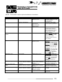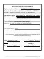
1
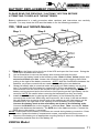
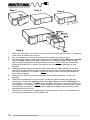
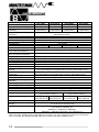
Uninterruptible Power Supply User’s Manual Pro Series User’s Manual 1. Introduction 2 2. Controls and Indicators 4 3. Installation 6 4. Operation 8 5. Troubleshooting 9 6. Replacing the Battery 10 7. Obtaining Service 13 8. Specifications 14 9. Configurable Parameters & Settings 15 10. Limited Warranty 16 Copyright Para Systems, Inc., 1998 1 Thank you for purchasing a Minuteman power protection product. It has been designed and manufactured to provide many years of trouble free service. IMPORTANT SAFETY INSTRUCTIONS SAVE THESE INSTRUCTIONS ! Please read the manual before installing your Pro Series UPS as it provides the information that should be followed during installation and maintenance of the UPS and batteries allowing you to correctly set up your system for the maximum safety and performance. Included is information on customer support and factory service if it is required. If you experience a problem with the UPS, please refer to the Troubleshooting guide in this manual to correct the problem or collect enough information so that the Minuteman technical support department can rapidly assist you. NOTICE: This equipment has been tested and found to comply with the limits for a Class A digital device, persuant to part 15 of the FCC rules. These limits are designed to provide reasonable protection against harmful interference when the equipment is operated in a commercial environment. This equipment generates, uses and can radiate radio frequency energy and, if not installed and used in accordance with the instruction manual, may cause interference to radio communications. Operation of this equipment in a residential area is likelly to cause harmful interference, in which case the user will be required to correct the interference at his own expense. This digital apparatus does not exceed the Class A limits for radio noise emissions from digital apparatus set out in the Radio interference regulations of the Canadian Department of Communications. Le présent appareil numérique n’emit pas de bruits radioélectriques dépassant les limites applicables aus appareils numérique de las Class A prescrites dans le Règlement sur le brouillage radioélectrique édicte par le ministèredès Communications du Canada. WARNING: Changes or modifications to this unit not expressly approved by the party responsible for compliance could void the user’s authority to operate the equipment. 2 Receiving Inspection After removing your Minuteman UPS from its carton, it should be inspected for damage that may have occurred in shipping. Immediately notify the carrier and place of purchase if any damage is found. Warranty claims for damage caused by the carrier will not be honored. The packing materials that your UPS was shipped in are carefully designed to minimize any shipping damage. In the unlikely case that the UPS needs to be returned to Minuteman, please use the original packing material. Since Minuteman is not responsible for shipping damage incurred when the system is returned, the original packing material is inexpensive insurance. PLEASE SAVE THE PACKING MATERIALS! WARNING: RISK OF ELECTRICAL SHOCK. HAZARDOUS LIVE PARTS INSIDE THIS POWER SUPPLY ARE ENERGIZED FROM THE BATTERY EVEN WHEN THE AC INPUT POWER IS DISCONNECTED. TO DE-ENERGIZE THE OUTPUTS OF THE UPS: 1. IF THE UPS IS ON PRESS THE ON/OFF BUTTON FOR 1 SECOND. 2. DISCONNECT THE UPS FROM THE AC POWER OUTLET. 3. TO DE-ENERGIZE THE UPS COMPLETELY, DISCONNECT THE BATTERY. (SEE SECTION 6 FOR INSTRUCTIONS) CAUTION! TO REDUCE THE RISK OF ELECTRICAL SHOCK IN CONDITIONS WHERE LOAD EQUIPMENT GROUNDING CANNOT BE VERIFIED, DISCONNECT THE UPS FROM THE AC POWER OUTLET BEFORE INSTALLING A COMPUTER INTERFACE CABLE. RECONNECT THE POWER CORD ONLY AFTER ALL SIGNALING CONNECTIONS ARE MADE. CAUTION! CONNECT THE UPS TO A TWO POLE, THREE WIRE GROUNDING AC POWER OUTLET. THE RECEPTACLE MUST BE CONNECTED TO APPROPRIATE BRANCH PROTECTION (CIRCUIT BREAKER OR FUSE). CONNECTION TO ANY OTHER TYPE OF RECEPTACLE MAY RESULT IN A SHOCK HAZARD AND VIOLATE LOCAL ELECTRICAL CODES. Para Systems Life Support Policy ! " # $ " %& ' () * + ,-$. ' + ,-$. * / + ,-$. " - # 3 FRONT PANEL Pro 700, 1000, 1400r front panel Pro 2200r front panel Press and release the ON/OFF button after one beep to turn the unit on or off. (see section 4) online on-battery boost and buck The online/on battery/boost and buck LED illuminates in a steady state when the UPS is on and supplying AC power to the load, blinks (5 times per second) and sounds the audible alarm when supplying battery power to the load, blinks (once per second) with no audible alarm when the automatic voltage regulator is in operation. TEST Press and release the TEST/Alarm silence button to test the UPS or silence the alarm.(see section 4) The fault LED illuminates when the UPS has detected an internal fault (contact Minuteman technical support). The overload LED illuminates when the loads connected to the UPS exceeds the UPS power rating (see section 4). The replace battery LED illuminates when the UPS has detected that battery replacement is required (see section 6). 4 Input Circuit Breaker Pro 700, 1000 and 1400r Rear Panel Output Receptacles Accessory Slot Option Slots DB9 Connector RJ-45/RJ-11 Protection Site Wiring Fault Input Power Pro 2200r Rear Panel Input Circuit Breaker Input Power REAR PANEL DB9 Connector Site Wiring Fault External Battery Connector Option Slot Output Receptacles Output Circuit Breaker Accessory Slot RJ-45/RJ-11 Protection The Accessory Slot is used for SNMP UPS monitoring, power control, multiple server support, and special signaling (see section 3). The DB9 connector is used for UPS monitoring and control through a computer’s serial port (see section 3). The RJ-45/RJ-11 modular connectors are used for 10 Base-T network/single line telephone surge protection (see section 3). The Option slots are for adding extra RJ-45/RJ-11 surge protection cards. Available from Minuteman. The Site Wiring Fault LED illuminates when the UPS detects an improperly wired AC power outlet (only available on 115V models). The Output Power receptacles are NEMA 5-15R type (IEC output sockets on 230Vac models). The Input Power cord has a NEMA 5-15P connector (IEC input socket on 230Vac models, L5-30P for Pro 2200r 115V model). The Input Circuit Breaker will trip in the event the load exceeds the UPS’s power rating. The Output Circuit Breakers will trip in the event the load exceeds the UPS’s power rating (2200 115V model only). The External Battery connector is for adding m ore battery capacity to th e U P S (see section 3). 5 INSTALLATION PLACEMENT Please observe the following items; The UPS comes with standard 19” (46.5 cm) rack mount brackets installed. These brackets are reversible for mounting to a standard 23” (59.2 cm) rack. Screws are not supplied with the UPS for attaching it to the rack (for screw size varies according to rack size). Install the UPS in a temperature controlled, indoor environment that is free of conductive contaminants. Select a location which will provide good air circulation for the UPS at all times. Avoid locations near heating devices, water or excessive humidity, or where the UPS is exposed to direct sunlight. Select a location sturdy enough to handle the weight of the UPS. Two additional sets of bracket holes are located on the sides of the UPS to allow for the UPS to be mounted with a different set back. After moving the bracket to these holes, make sure the rack will not tip. After mounting is complete, plug the UPS in to a two pole, three wire, grounded receptacle. Route power cords so they cannot be walked on or damaged. WARNING: Care should be taken when installing the units due to their weight. Use two or more people when installing. Do not move the rack after the UPS is installed (the position of the UPS’s weight may cause the rack to be unstable during movement). ACCESSORY SLOT (OPTIONAL) This slot is used for optional accessories available from Minuteman. information. Call for more DB9 CONNECTOR Minuteman Power Management software and interface cables kits are used with this port (software and cables are optional and available from Minuteman). Use only Minuteman or Minuteman approved interface cables with these UPS’s. Connect the interface cable to the DB9 connector on the rear of the UPS. Secure the connector to the UPS via the screws on the connector housing. Connect the other end of the cable to the device that will be monitoring/controlling the UPS. NOTE: CONNECTING TO THE DB9 IS OPTIONAL. THE UPS WORKS PROPERLY WITHOUT A CONNECTION. 6 RJ-45/RJ-11 PROTECTION Connect a single line telephone or a 10 Base-T network line to the protection sockets on the rear of the UPS. This connection will require another length of telephone or network cable. The cable coming from the telephone service or networked system is connected to the port marked “IN”. The port marked “OUT” is connected to the equipment to be protected. NOTE: CONNECTING TO THIS PORT IS OPTIONAL. THE UPS WORKS PROPERLY WITHOUT A CONNECTION. SITE WIRING FAULT (115V models only) After plugging in the UPS, check the site wiring fault (SWF) LED on the rear of the unit. If the LED is illuminated, the UPS is plugged into an improperly wired AC outlet. CAUTION!: IF THE UPS INDICATES A SITE WIRING FAULT, HAVE A QUALIFIED ELECTRICAN CORRECT THE PROBLEM. EXTERNAL BATTERY CONNECTOR This is an option that is only available on the 2200VA UPS. This is an optional connection for this UPS. The 2200 has internal batteries. The battery pack is available from Minuteman (PRO BP1). Only one battery pack may be connected to the UPS to extend its runtime. Use only the Pro BP1 battery pack with this UPS. The use of any other battery pack may damage the UPS and void the warranty. CHARGING THE BATTERIES The PRO Series UPS’s will charge the batteries whenever the unit is connected to an AC source. It is recommended that the UPS batteries be charged for a minimum of 4 hours before use. The UPS may be used immediately. However, the “on battery” run time may be less than normally expected. CONNECTING YOUR EQUIPMENT Plug the equipment into the receptacles on the rear of the unit. Insure that you do not exceed the maximum output rating of the UPS (refer to the back panel of the UPS or the electrical specifications in this manual). CAUTION! DO NOT CONNECT A LASER PRINTER TO THE UPS UNLESS THE UPS IS RATED 2000VA OR GREATER. A LASER PRINTER DRAWS SIGNIFICANTLY MORE POWER WHEN PRINTING THAN AT IDLE AND MAY OVERLOAD THE UPS. 7 TURNING THE UNIT ON/OFF ON/OFF SWITCH Press and release the ON/OFF switch after one beep to turn the unit on and supply power to the load. The load will be immediately powered and 2 seconds later the UPS will run a 15 second self test before returning the load to the AC line. Press and release the switch again to turn the UPS off. The UPS will continue to charge the batteries whenever it is plugged in and AC line is present. SELF TEST TEST TEST SWITCH The self test feature is useful to verify the correct operation of the UPS and the condition of the battery. With the UPS plugged into normal AC, press and release the TEST/Alarm silence switch to initiate a self test. When the UPS is in battery mode, press and release the TEST/Alarm silence switch to silence the alarm. NOTE: The UPS will automatically perform a self test on startup and every two weeks. During the self test the UPS will switch to battery power and the on-line LED will blink and the audible alarm will sound as well. This test will run for approximately fifteen seconds to measure the battery’s capability to provide an acceptable amount of runtime. If the UPS fails a self test, one of the LED’s will remain illuminated indicating the type of problem (see section 5 Troubleshooting). ALARMS ON BATTERY When the UPS is operating on the batteries, the on-line LED will blink and the audible alarm will sound every 10 seconds. The alarm will stop once the UPS returns to on-line operation. UPS FAULT When the UPS detects a hardware fault, the fault LED will illuminate and the UPS will emit a sustained tone. The fault condition can be re-set by turning the UPS off and then on or by pressing the test switch (see section 5 for more information). OVERLOAD When the amount of load attached to the UPS exceeds its power rating, the overload LED will illuminate and the UPS will emit a sustained tone. This alarm will remain on until the excess load is removed or the UPS’s self protection circuit shuts the UPS down. 8 REPLACE BATTERY The UPS automatically tests the battery’s condition and will illuminate the replace battery LED and emit a short beep. This tone will be repeated every hour until the battery passes a self test. It is recommended that the UPS be allowed to charge overnight before performing a battery test to confirm a replace battery condition. LOW BATTERY WARNING The UPS will emit a steady tone when the battery reserve runs low. It continues to emit the steady tone until AC returns or the UPS shuts down from battery exhaustion. TROUBLESHOOTING CHART Symptom UPS will not turn on Possible Cause On/Off button not pushed UPS operates in battery mode only, even though there is normal AC present Input AC breaker is tripped Fault LED is illuminated UPS has detected an internal fault Incorrect service wiring The Site Wiring Fault LED is illuminated The Online/On Battery LED is illuminated, but there is no output The UPS is being controlled via its communications port UPS does not provide expected backup time The batteries may be weak or at the end of useful service life Replace Battery LED is illuminated Weak or bad batteries, or bad battery connection The UPS occasionally emits a beep Normal operation What To Do Press On button momentarily (one beep) to start UPS Reset circuit breaker by pressing the plunger back in. Circuit breaker trips after UPS starts up, reduce the load on the UPS Call for service Have a qualified electrician correct the service wiring Disconnect the communications cable from the UPS and press the On button momentarily. If the UPS works normally, software has control of the UPS Charge the batteries for 8 hours and retest. If the backup time is still less than expected, the batteries may need to be replaced, even though the Replace Battery LED is not illuminated Check the battery connection and/or replace the batteries. Follow battery replacement procedures in Section 6 The UPS is performing its intended function 9 REPLACING THE BATTERY The PRO Series UPS has an easy to replace hot-swappable batteries. Please read the following warning statements before attempting to service the batteries. WARNING! THIS UNINTERRUPTIBLE POWER SOURCE CONTAINS POTENTIALLY HAZARDOUS VOLTAGES. DO NOT ATTEMPT TO DISASSEMBLE THE UNIT BEYOND BATTERY REPLACEMENT PROCEDURES BELOW. EXCEPT FOR THE BATTERY, THIS UPS CONTAINS NO USER SERVICABLE PARTS. REPAIRS CAN BE PERFORMED BY MINUTEMAN SERVICE PERSONNEL ONLY. CAUTION: DO NOT OPEN OR MUTILATE BATTERIES. RELEASED ELECTROLYTE IS HARMFUL TO THE SKIN AND EYES AND MAY BE TOXIC CAUTION: DO NOT DISPOSE OF BATTERIES IN A FIRE. THE BATTERIES MAY EXPLODE. THE BATTERIES IN THIS UPS ARE RECYCLABLE. DISPOSE OF THE BATTERIES PROPERLY. THE BATTERIES CONTAIN LEAD AND POSE A HAZARD TO THE ENVIRONMENT AND HUMAN HEALTH IF NOT DISPOSED OF PROPERLY. REFER TO LOCAL CODES FOR PROPER DISPOSAL REQUIREMENTS OR RETURN THE BATTERY TO MINUTEMAN. CAUTION: ALTHOUGH BATTERY SYSTEM VOLTAGES ARE ONLY 24 VDC AND 48 VDC, THE BATTERY SYSTEM CAN STILL PRESENT A RISK. THE CURRENT CAPABILITY OF A BATTERY IS SUFFICENT TO BURN WIRE OR TOOLS VERY RAPIDLY, PRODUCING MOLTEN METAL. OBSERVE THESE PRECAUTIONS WHEN REPLACING THE BATTERIES: 1. REMOVE WATCHES, RINGS, OR OTHER METAL OBJECTS; 2. USE HAND TOOLS WITH INSULATED HANDLES; 3. DO NOT LAY TOOLS OR OTHER METAL PARTS ON TOP OF BATTERIES CAUTION: WHEN DISCONNECTING THE INTERNAL BATTERIES OR THE EXTERNAL BATTERY PACK, THE UPS CANNOT BE RUNNING IN THE BATTERY MODE. THE UPS MUST BE OFF OR SUPPLYING POWER TO THE LOAD FROM THE UTILITY MAINS. CAUTION: REPLACE BATTERIES WITH THE SAME NUMBER AND TYPE AS ORIGINALLY INSTALLED IN THE UPS. THESE BATTERIES HAVE PRESSURE OPERATED VENTS. 10 BATTERY REPLACEMENT PROCEDURE PLEASE READ THE PREVIOUS “CAUTIONS” SECTION BEFORE ATTEMPTING TO REPLACE THE BATTERIES Battery replacement is a safe procedure when cautions and instructions are carefully followed. You may leave the UPS and the loads on for the following procedure. 700, 1000 and 1400VA Models Step 1 Step 2 Step 3 Reach4into the finger pull on the front of the UPS and open the front cover. Swing the 1. Step cover open as shown and remove. Use a screwdriver to remove the battery door screws and open the door. Disconnect the battery leads in the following order. Red wire first. Yellow jumper wire second and Black wire last. Loosen the connectors by gently wiggling them while pulling to the right of the battery connector. NOTE: Note the connections between the batteries, so proper connections are made when installing the new batteries. 4. Grasp the battery tabs in numerical order and gently pull each battery out one at a time. For models with four batteries, repeat step 3 for the rear batteries. NOTE: The red and black wire will need to be moved to the right side of the opening so the left battery can be removed and to the left side of the opening so the right battery can be removed. NOTE: Be careful when removing the batteries since they are heavy. 5. Install the new batteries by placing the right battery in first followed by the left (reversing the order from which they were removed). As in step 4, the red and black wire will need to be moved to the left side of the opening so the right battery can be installed and to the right side of the opening so the left battery can be installed. Connect the battery leads to the new battery as shown in the following order. Connect the BLACK wire to the negative (-) terminal first. Then connect the Yellow jumper wire between the batteries. The RED wire is the last connection. Connect the RED wire to the positive (+) terminal. NOTE: Small sparks at the battery connection are normal during battery connection. Close the door, replace the battery compartment screws, and replace the front cover. 6. Dispose of the battery at an appropriate recycling facility or return it to Minuteman in the packing material from the new battery kit. 2. 3. 2200VA Model 11 Step 1 Step 2 Step 3 Step 4 1. 2. 3. 4. 5. 6. 7. 12 Reach into the finger pull on the front of the UPS and open the front cover. Swing the cover open as shown and remove. Use a screwdriver to remove the battery door screws and open the door. Disconnect the battery leads in the following order. Red wire first. Black wire second and the Yellow jumper wires last. Loosen the connectors by gently wiggling them while pulling straight back from the battery connector. NOTE: Note the connections between the batteries, so proper connections are made when installing the new batteries. Grasp the battery tabs in numerical order and gently pull each battery out one at a time. After the front batteries are removed, grasp the two remaining battery tabs and pull the rear batteries out together. NOTE: Be careful when removing the batteries since they are heavy. Remove the Yellow jumpers from the old batteries and install them on the new batteries. Install the new batteries in reverse order of removal. When making the final wire connection, connect the Yellow jumper wires first. Then connect the BLACK wire to the negative (-) terminal. The RED wire is the last connection. Connect the RED wire to the positive (+) terminal. NOTE: Small sparks at the battery connection are normal during battery connection. Close the door, replace the battery compartment screws, and replace the front cover. Dispose of the battery at an appropriate recycling facility or return it to Minuteman in the packing material from the new battery kit. IF THE UPS REQUIRES SERVICE 1. Use the TROUBLESHOOTING section 5 to eliminate obvious causes. 2. Verify that no circuit breakers are tripped. A tripped circuit breaker is the most common problem. Call your dealer for assistance. If you cannot reach your dealer, or if he cannot resolve the problem. call or FAX Minuteman Technical Support at the following numbers: Voice phone (972) 446-7363, FAX line (972) 446-9011, e-mail: [email protected]. Please have the following information available BEFORE calling technical support. A. Your Name and address. B. Where and when the unit was purchased. C. All of the model information on the rear of your Pro Series UPS. D. Any information on the failure, including LEDs that may be illuminated. E. A description of the protected equipment, including model numbers if possible. F. A technician will ask you for the above information and, if possible, help solve your problem over the phone. In the event that the unit requires factory service, the technician will issue you a Return Material Authorization Number (RMA #). G. If the UPS is under warranty, the repairs will be done at no charge. If not, there will be a charge for repair. Pack the UPS in its original packaging. If the original packaging is no longer available, ask the technical support technician about obtaining a new set. It is important to pack the UPS properly in order to avoid damage in transit. Never use Styrofoam beads for a packing material. Include a letter with your name, address, day time phone number, RMA number, a copy of your original sales receipt, and a brief description of the trouble. Mark the RMA # on the outside of all packages. The factory cannot accept any package without the RMA # marked on the outside. Return the UPS by insured, prepaid carrier to: 3. 4. 5. 6. Minuteman, Para Systems Inc. 1455 LeMay Drive Carrollton, Tx. 75007 13 NOTE: 230V Specs Shown in ( ) Pro 700r Pro 1000r Pro 1400r Pro 2200r Nominal input voltage 115V (230V) 115V (230V) 115V (230V) 115V (230V) *Acceptable input voltage 92-150 (176-282) 92-150 (176-282) 92-150 (176-282) 92-150 (176-282) *Output voltage (on-line 103V-131V 103V-131V 103V-131V 103V-131V operation) (196V-253V) (196V-253V) (196V-253V) (196V-253V) Output voltage (Battery Nominal voltage ± 5%, -10% after low battery warning. operation) Simulated sine wave Nominal input frequency 50 or 60Hz, autosensing Frequency limits(on-line) 50 or 60 Hz +/- 3 Hz Frequency (Battery operation) 50 or 60 Hz +/- 1 Hz Input protection Resettable circuit breaker Transfer time 4 ms typical Maximum load VA/Watts 700VA/450W 1000VA/670W 1400VA/950W 2200VA/1600W Protection Overcurrent and short-circuit protected, latching shutdown on overload Surge energy rating(one time, 480 Joules 10 to 1000 us waveform) Surge current capability (one 6500 A maximum time, 8 to 20 us waveform) Surge response time 0 ns (instantaneous) normal mode, <5ns common mode Surge voltage let-through < 0.3 % of peak, typical Noise filter Normal and common mode EMI/RFI suppression, 100 kHz to 10 MHz Battery Type Hot-swappable, Spill-proof, sealed lead acid, maintenance-free Typical battery life 3 to 5 years Typical recharge time 4 hours 10 Base-T surge protection let<5% through (As a percentage of an applied ±6kV 1.2/50µs, 500A 8/20µs test) Telephone line surge protection 1% let-through (As a percentage of an applied ±6kV 1.2/50µs, 500A 8/20µs test) Operating temperature 0 to +40 degrees C (+32 to 104 degrees F) Storage temperature -15 to +45 degrees C (+5 to +113 degrees F) Operating and storage relative 0 to 95% non-condensing humidity Operating elevation 0 to +3000 m (0 to +10,000 ft) Electromagnetic immunity IEC 801-2 level IV, 801-4 level IV, 801-5 level III Audible noise in dbA at 1 meter < 45 Audible alarm On Overload, Low battery warning, On battery Communications port DB-9 Minuteman standard, optional SNMP Size (H x W x D) 8.9 X 48.3 X 45.3 cm 13.2 X 48.3 X 50.4 cm (3.5 X 19.0 X 17.8 in) (5.2 X 19.0 X 19.8 in) Weight net (shipping) 19.8 (22.1) Kg 26.6 (28.9) Kg 29.7 (32.0) Kg 46.4 (49.1) Kg 43.6 (48.6) Lb 58.6 (63.6) Lb 65.4 (70.4) Lb Battery pack Battery pack size (HxWxD) and weight Conformance 102 (108) Lb Available on the 2200 only (Pro BP1) 8.9 X 48.3 X 45.3 cm (32.1 Kg) 3.5 X 19.0 X 17.8 in (70.7 Lb) UL 1778, CSA C22.2, FCC Class A, TUV/GS, CE, EN50091-1, EN50091-2, EN60950, EN50082-1, EN55022, EN61000-3-2 & EN61000-3-3 *Note: The input voltage range is adjustable via software. For input voltages less than 8% or more than 12% of nominal, the voltage regulator will boost or reduce the input voltage by 15%. 14 NOTE: These items require optional software or hardware. Function Factory Default User Choices Description UPS ID Model number Up to 64 characters to define the UPS Battery install date Date of manufacture Battery life in days 1826 Date of battery replacement day/month/year XX/XX/XXXX Up to 5 characters Use this function to uniquely identify the UPS in your network configuration Enter the current date when replacing batteries Enable/Disable auto restart Enabled Enable or disable When enabled, the UPS will automatically restart from a low battery shutdown when normal A/C returns Set audible alarm state Enabled Enabled, at low battery, disabled, Mute Shutdown Type UPS output UPS output or UPS Set low voltage Xfer point 92 VAC (176 for 230VAC models) Set high voltage Xfer point 150 VAC (282 for 230VAC models) Set nominal input voltage 115 VAC (230 for 230VAC models) Baud Rate 9600 92 or 88 VAC (176 or 166 for 230VAC models) 150 or 145 VAC (282 or 272 for 230VAC models) 110,115,120 VAC (220, 230, 240 for 230VAC models) 1200, 2400, 4800, 9600 Enabled - the UPS will emit a short beep when in the battery mode. At Low Battery the UPS will emit a steady tone only at low battery warning through shutdown. Disabled - Use only when software is controlling the UPS or to silence the alarm Mute - Attenuates the alarm by 50% UPS Output - When the UPS is told to shut down, it turns off the UPS output only. UPS - Turns off the UPS which requires the UPS to be turned on manually Changes the voltage point at which the UPS switches to battery power Changes the voltage point at which the UPS switches to battery power Changes the output voltage At first battery replacement, reset to reflect actual number of days experience in your environment or leave factory default. Sets the communication baud rate 15 LIMITED PRODUCT WARRANTY 10 LIMITED PRODUCT WARRANTY Para Systems Inc. (Para Systems) warrants this equipment, when properly applied and operated within specified conditions, against faulty materials or workmanship for a period of three years from the date of original purchase by the end user. For equipment sites within the United States and Canada, this warranty covers repair or replacement of defective equipment at the discretion of Para Systems. Repair will be from the nearest authorized service center. Replacement parts and warranty labor will be borne by Para Systems. For equipment located outside of the United States and Canada, Para Systems only covers faulty parts. Para Systems products repaired or replaced pursuant to this warranty shall be warranted for the unexpired portion of the warranty applying to the original product. This warranty applies only to the original purchaser who must have properly registered the product within 10 days of purchase. The warranty shall be void if (a) the equipment is damaged by the customer, is improperly used, is subjected to an adverse operating environment, or is operated outside the limits of its electrical specifications; (b) the equipment is repaired or modified by anyone other than Para Systems or Para Systems-approved personnel; or (c) has been used in a manner contrary to the product’s operating manual or other written instructions. Any technical advice furnished before or after delivery in regard to use or application of Para Systems’ equipment is furnished without charge and on the basis that it represents Para Systems’ best judgment under the circumstances, but it is used at the recipient’s sole risk. EXCEPT AS PROVIDED HEREIN, PARA SYSTEMS MAKES NO WARRANTIES, EXPRESSED OR IMPLIED, INCLUDING WARRANTIES OF MERCHANTABILITY AND FITNESS FOR A PARTICULAR PURPOSE. Some states do not permit limitation of implied warranties; therefore, the aforesaid limitation(s) may not apply to the purchaser. EXCEPT AS PROVIDED ABOVE, IN NO EVENT WILL PARA SYSTEMS BE LIABLE FOR DIRECT, INDIRECT, SPECIAL, INCIDENTAL, OR CONSEQUENTIAL DAMAGES ARISING OUT OF THE USE OF THIS PRODUCT, EVEN IF ADVISED OF THE POSSIBILITY OF SUCH DAMAGE. Specifically, Para Systems is not liable for any costs, such as lost profits or revenue, loss of equipment, loss of use of equipment, loss of software, loss of data, cost of substitutes, claims by third parties, or otherwise. The sole and exclusive remedy for breach of any warranty, expressed or implied, concerning Para Systems’ products and the only obligation of Para Systems hereunder, shall be the repair or replacement of defective equipment, components, or parts; or, at Para Systems’ option, refund of the purchase price or substitution with an equivalent replacement product. This warranty gives you specific legal rights and you may also have other rights which vary from state to state. Longer term and F.O.B. job site warranties are available at extra cost. Contact Para Systems (1-972-446-7363) for details. 16 DECLARATION OF CONFORMITY Application of Council Directive(s): 89/336/EEC, 73/23/EEC Standard(s) to which Conformity is Declared: EN50091-1, EN50091-2 EN50082-1, EN55022, EN60950, EN61000-3-2, EN61000-3-3 Manufacturer’s Name: Para Systems, Inc. (Minuteman Power Supplies) Manufacturer’s Address: 1455 LeMay Drive Carrollton, Texas 75007 USA Type of Equipment: Uninterruptible Power Supplies Model No: Pro 700ri, Pro 1000ri, Pro 1400ri, Pro 2200ri Year of Manufacture: 1998, I, the undersigned, hereby declare that the equipment specified above conforms to the above Directive(s). Place: Carrollton, Tx USA (Signature) Date: November 1, 1998 Shawn Delavar (Full Name) Regulatory Compliance Engineer 17 Para Systems, Inc. 1455 LeMay Dr. Carrollton, TX 75007 Phone: (972) 446-7363 Fax: (972) 446-9011 QuickFax Info System: 1-800-263-3933 Internet: www minuteman-ups.com PN: 34000033 Rev. 1