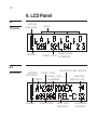
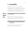
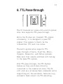
1
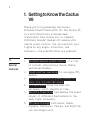
User Manual
Wireless
Flash
Transceiver
V6
2
Table of Contents
1. Getting to Know the Cactus V6
4
2. Cautions and Warnings
7
3. Major Specifications
8
4. Package Contents
9
5. Nomenclature
10
6. LCD Panel
12
7. Compatibility
13
8. TTL Pass-through
17
9. Getting Started
19
10.Flash Profile:
Choosing, Learning, and Copying
29
11.Flash Triggering
37
12.Remote Manual Power Control
39
3
13.Camera Shutter Release
49
14.Advanced Operations
54
15.Personalizing the V6
59
16.Working with Cactus Gear
63
17.LED Signal Guide
68
18.USB Connection
69
19.Optional Accessories
71
20.Troubleshooting
72
21.Notices
78
22.Warranty
81
4
1. Getting to Know the Cactus V6
Thank you for purchasing the Cactus
Wireless Flash Transceiver V6. The Cactus V6
is a multifunctional wireless flash
transceiver that allows you to command
different brands’ flashes off camera with
remote power control. You can position your
lights at any angle, direction, and
distance — the possibilities are endless!
1.1
Special
Features
1.Wireless manual power control of a list
of current and previous Canon, Nikon,
and Pentax flashes.
2.Flash profile learning for analogue-TTL
flashes.
3.Full manipulation of power levels to
1/10, 1/3, 1/2 and 1EV steps.
4.Lo Power mode fires the flash for
extremely short lengths of time.
5.Absolute Power Mode benchmarks the power
output of different flash models to the
same light intensity.
6.TTL pass-through with Canon, Nikon,
Olympus, Panasonic, Pentax, and Fujifilm
via one single unit.
5
7.Built-in optical trigger enables
pre-flash triggering.
8.Group control allows you to control up to
four groups.
9.Relay mode triggers the camera shutter
and flash in sync.
10.Delay timer is configurable from
1 millisecond to 10 seconds.
11.Mini-USB port for optional power supply
and firmware updates.
1.2
Cactus V6
Core
Each flash model has its individual power
level characteristics. We have profiled more
than 30 popular flash models across a wide
range of brands so that the V6 can precisely
control their output levels. With this
unique feature, photographers can remotely
control the flash power of various flash
models, even of different brands!
For flash models that have not been included
in the profile list, the V6 can still work
with it by learning its flash profile. Check
Section 7.1.3 for details of which flashes
are eligible for the flash profile learning
program.
6
Whether built-in or obtained from the
learning program, the flash profile stored
in the V6 can virtually command the flash to
produce ANY power level within the maximum
output, and even exceeds what the flash menu
allows you to do:
1. Finer increment scales: The V6 can
adjust the power level of flash to 1/10 EV
step, a much finer increment level than
the flash menu itself allows (see
Section 12.3 for setting up the EV step).
2. Extremely short firing time: In Lo Power
mode, the V6 can fire flashes for very
short lengths of time at extremely low
power levels (roughly equal to 1/256),
which is beyond the standard flash power
range (see Section 12.4 for enabling the
Lo Power output).
3. Unified power level scale for different
flash models: The V6 benchmarks the light
intensity output of different flash
models in your set up and commands them
to fire at the same power scale (see
Section 12.2 for adjusting absolute
power).
Ready to go? Let’s get on board and see what
the V6 can do!
7
2.Cautions and Warnings
Before using your V6, read the following
safety precautions to ensure correct and
safe use:
1. Turn OFF all your equipment (e.g., Cactus
units, flash units, cameras, etc.) before
changing batteries or making
connections. Observe the correct
polarity when changing batteries. There
is a danger of explosion if the batteries
are installed incorrectly.
2. Switch off the transceiver and remove
batteries during storage.
3. Do not permanently store the product in
a high temperature environment (i.e.,
under strong direct sunlight, near
cooking stoves/oven).
4. The Cactus V6 should never be
submerged in liquid or exposed to heavy
rain unless it is properly protected.
5. Do not operate the device in the presence
of flammable gases or fumes.
6. Do not dissemble.
7. Do not crush and do not expose the V6 to
any shock or force such as hammering,
dropping, or stepping on it.
8
3.Major Specifications
•
•
•
•
•
•
•
•
•
•
•
•
Working radio frequency: 2.4 GHz
Number of channels: 16
Number of groups: 4
Support sync speed up to 1/1,000 second
(subject to camera’s sync speed
limitation)
Maximum effective distance: 100 meters
Operating temperature: -20°C to +50°C
Camera voltage handling: up to 6V
Flash voltage handling: up to 300V
Dimensions:
72mm (L) x 72mm (W) x 42 mm (H)
Weight: 68g
Power input: 2 x AA battery, 3V, 50mA,
0.15W; mini USB 2.0, DC input 5V, 500mA~1A
Estimated battery life:
Battery life
(hours)
Alkaline AA
Batteries
1000mAh
Rechargeable
NiMH AA
Batteries
2500mAh
TX
RX
TX
LCD Backlight Off
40
21
67
RX
34
LCD Backlight On
25
17
36
25
9
4.Package Contents
V6 Transceiver
Album &
User Manual
Flash Stand FS-2
10
5.Nomenclature
MULTI-SYSTEM
SHOE (FEMALE)
TEST BUTTON/
SHUTTER RELEASE
BUTTON
LCD DISPLAY
LANYARD
LOOP
OPTICAL
SENSOR
GROUP BUTTONS
X-SYNC PORT
MINI USB PORT
MODE SWITCH
11
MULTI-SYSTEM
SHOE (MALE)
TRIPOD MOUNT
HOT SHOE
LOCK LEVER
SELECTION DIAL
BATTERY DOOR
OK BUTTON
MENU BUTTON
LED STATUS INDICATOR
12
6.LCD Panel
6.1
TX mode
BATTERY
INDICATOR
CHANNEL
GROUP
POWER LEVEL
POWER LEVEL INCREMENT
6.2
RX mode
SELECTED FLASH PROFILE
POWER LEVEL
BATTERY
INDICATOR
WIRELESS
POWER LEVEL
INCREMENT
SENSITIVITY
GROUP
CHANNEL
DELAY TIMER
RELAY MODE
INDICATOR
SLAVE MODE
INDICATOR
13
7. Compatibility
The Cactus V6 is both a wireless flash
trigger and wireless remote control. While
it triggers both portable flashes and studio
strobe lights, it also supports remote
control features with selected flash models.
7.1
Flash &
Studio
Strobes
7.1.1 Cactus RF60
With the built-in Cactus V6 module, the
Cactus RF60 can be remotely commanded and
triggered by V6 TX (see Section 16.1.1).
7.1.2 Flash Models with a Pre-installed Prof ile in
the Cactus V6
The Cactus V6 can remotely control the
following portable flash models:
14
FLASH SYSTEM
FLASH MODEL
CANON
CACTUS AF45C, AF50C;
CANON 320EX, 420EX, 430EX*, 430EZ,
540EZ, 580EX*, 600EX-RT;
GODOX V860C;
METZ 36AF-5, 44AF-1, 50AF-1, 52AF-1,
58AF-1, 58AF-2;
NISSIN Di866 MARK II, MG8000;
PHOTTIX MITROS;
SIGMA EF-500 DG SUPER;
YONGNUO YN568EX*;
NIKON
CACTUS AF45N, AF50N;
METZ 36AF-5, 44AF-1, 50AF-1, 58AF-2;
NIKON SB-24, SB-28, SB-600, SB-700,
SB-800, SB-900, SB-910;
NISSIN Di700, Di866;
SIGMA EF-530 DG SUPER;
PENTAX
CACTUS AF45P, AF50P;
METZ 36AF-5, 44AF-1, 50AF-1, 58AF-2;
PENTAX AF 360FGZ, AF 540FGZ;
* profiles working with different versions of the
model (e.g., 580EX II and 580EX)
7.1.3 Flash Models with Analogue TTL Mode
The Cactus V6 can learn the profiles of
other flash models that come with an analogue
TTL mode, i.e., the TTL operated analogue
quench signals. If your flashes come with a
TTL mode that does not have an initial
before TTL (e.g., E-TTL or E-TTL II from
15
Canon, i-TTL or i-TTL BL from Nikon, or
P-TTL from Pentax), their flash profiles may
be learned and remotely controlled by the
Cactus V6.
7.1.4 Other Flash Models and Studio Strobes
The Cactus V6 triggers all other flash models
via the hot shoe, and studio strobes with
the PC sync male port, 3.5mm or 6.35mm port
via optional cables (see Section 19). This
includes high trigger voltage portable flash
models, and all strobe models with a trigger
voltage of 300V or under. The Cactus V6 does
not provide remote power control of these
flashes and strobes.
Caution:
Flashes or strobes with reversed polarity
connectors DO NOT WORK with the Cactus V6.
7.2
Cameras
The Cactus V6 works with practically all
cameras that come with either (1) a standard
ISO hot shoe, or (2) a female sync port
connection.
16
To use the V6 as a wireless shutter release,
specific shutter cables are required. For
the list of optional accessories, see
Section 19.
7.3
Flash
Triggers
7.3.1 Cactus V5 and LV5
The Cactus V6 is compatible with the
Wireless Flash Transceiver V5 and Laser
Trigger LV5. See Section 16.2 for details.
7.3.2 Other Flash Triggers
The Cactus V6 is NOT compatible with any
other flash trigger model, including the
Cactus V2, Cactus V2s, and Cactus V4.
17
8.TTL Pass-through
The V6 transceiver comes with a multi-system
shoe that supports TTL pass-through.
While the V6 does not transmit TTL signal
wirelessly, it is designed to pass TTL
signal from camera to flash via the
transmitter (TX) and vice versa.
The multi-system shoe supports TTL
pass-through of Canon, Fujifilm, Nikon,
Olympus, Panasonic, and Pentax systems.
Make sure that camera and flash unit belong
to the same TTL system.
With TTL pass-through, the TTL flashes
behave as they would when directly
connected to the camera hot shoe. The V6
will work as a wireless flash commander while
supporting all the automatic features (e.g.,
automatic flash output via TTL metering,
18
AF assist light, second curtain sync, high
speed sync/FP shutter) provided by the TTL
flash system.
To enable TTL pass-through in the V6 TX,
press and hold
for 2 seconds. The LCD
will show the TTL pass-through indicator
at the left bottom corner where the channel
indicator used to be.
In TTL pass-through mode, the V6 TX cannot
control the power level of the flash
attached.
To disable the TTL pass-through mode, press
and hold
for 2 seconds. The TTL passthrough indicator will be replaced by the
channel indicator on the LCD.
19
9.Getting Started
9.1
Installing
the
Batteries
Open the battery door by pushing it
backward. Flip open the latch and insert two
AA batteries using the correct polarities.
Then close the battery door by pushing it to
the front.
9.2
Attaching
to and
Detaching
from the
Camera
UNLOCK
LOCK
To mount the V6 on a camera’s hot shoe mount:
1. Turn the lock lever of the V6 to the left
to unlock the multi-system shoe (male).
2. Slide the V6 into the camera’s hot shoe.
20
3. Turn the lock lever of the V6 to the
right to lock the multi-system shoe
(male).
4. When detaching the V6 from the camera’s
hot shoe, turn the lock lever to the left
to unlock the multi-system shoe (male).
Otherwise, the multi-system shoe (male)
may be damaged.
Note: Attach your flash to the V6 as you
would to the camera’s hot shoe. If your flash
is not locked securely on the Multi-System
Shoe (female), try half-locking the flash and
retracting it slightly from the Multi-System
Shoe until the locking pin hits the pinhole.
Then lock your flash fully to the V6.
9.3
Buttons
and Dial
The V6 control panel is equipped with a
Menu button
, an OK button
, and a
selection dial
for quick access to
different functions and the configuration
menu.
The selection dial has a built-in push-in
button that serves as a quick OK button. You
may configure how the dial works to suit
your working habit. (see Sections 15.1 15.3).
21
Major functions of the V6 listed below are
easily accessible by the buttons and dial.
Group Control (see Section 9.6)
Function
Mode
LCD
Key
Select a group
(e.g., group A)
for adjusting
parameters (power
level / zoom)
Main screen, Hold*
when the
group is not
selected
Deselect a group
(e.g., group A)
Main screen,
when the
group is
selected
Main screen,
when the
group is not
selected
Main screen
Turn on / off
a group (e.g.,
group A)
RX
Test firing a
group (e.g.,
group A)
Group EV Offset
in absolute power
mode (e.g., to
group A)
Change the RX to
another group
(e.g., to group A)
Main screen,
in absolute
power mode
+
+
Main screen
RX
* Hold = Press and hold the button for 2 seconds,
then release.
22
Adjusting Power Level and Zoom (see Sections
12.1 and 16.1)
Function
Mode
LCD
Adjust power level
of all groups
Main screen
Adjust power level
of a single group
(e.g., group A)
Main screen
Adjust power level
of the Master flash
Key
+
Hold
then
TX
Main screen
Quick power
adjustment
Main screen
Zoom (Cactus) mode
(needs
configuration in
menu beforehand)
Main screen
+
Navigating the Menu (see Section 9.7)
Function
Mode
Enter the menu
Browse through
menu items and
options
Choose a menu item
or option
Leave the menu
LCD
Main screen
Menu
TX /
RX
Menu
Menu
Key
,
23
TTL Pass-through / Flash Lock (see
Sections 8 and 10.1)
Function
Mode
Enter / leave TTL
pass-through mode
TX
Unlock the slave
flash
RX
LCD
Key
Main screen
Hold
Main screen
Hold
Dial Lock (see Section 15.2)
Function
Mode
Lock the dial
Temporarily
unlock the dial
LCD
Key
Main screen, Hold
when the dial
is unlocked
TX
Unlock the dial
Main screen,
when the dial
is locked
Main screen, Hold
when the dial
is locked
Firmware (see Section 18.2)
Function
Mode
Check firmware
version
Firmware update
mode
OFF
Key
Hold
+
and switch
on to TX or RX mode
Hold
and switch on
to TX or RX mode
24
9.4
Choosing
the
Operating
Mode
9.5
Setting
the
Channel
The Cactus V6 is a wireless transceiver that
is capable of transmitting and receiving
radio signals. Set the V6 transceivers to
the correct mode (transmitter to “TX”,
receiver to “RX”) by sliding the mode switch
to the correct position. This will
automatically power on the transceivers.
The Cactus V6 transceivers communicate with
each other via radio frequency. There are 16
channels available. Always make sure that
all of your V6 transceivers are set to the
same channel:
1. To set both TX and RX to the same
channel, press
. The LCD will show
<CHANNEL> and the default channel
number. Press
and turn the selection
dial to the preferred channel number.
Press
to set other menu items or press
to exit.
2. The selected channel number will be
displayed on the LCD screen.
25
9.6
Setting
and
Selecting
the Group
The group function in the V6 can assign RXs
into Group A, B, C, or D, and allows you to
choose which group(s) to fire from the TX
unit.
1. All V6 transceivers must be set to the
same channel.
2. Assign RX units to Groups A, B, C, or D by
pressing one of the group buttons. Each
RX can only be assigned to ONE group.
The LED of the selected group will turn
on.
3. Command the TX to fire any combination
of groups by pressing the group
button(s). You can fire any combination
of A, B, C, and D groups. The LED of the
activated group(s) will turn on.
4. To change the power level of a specific
group, press and hold an activated group
button. Quickly pressing the group
button again will de-select the group.
26
5. Pressing the group button(s) of activated
groups again on the V6 TX will turn off
the group(s). The V6 RX units that have
been set to the off group(s) will not
fire.
6.The V6 will memorize the group selection
in both TX and RX when it is switched
off. Next time you switch on the V6 it
will start up with the saved setting.
9.7
Navigating
the Menu
There are a number of configurable menu
options in the V6.
To change a menu option:
1.Press
to bring up the first menu
item.
2. Dial right or left to scroll through each
menu item.
3.Press
or push-in button once to
access a menu item.
4. Dial right or left to scroll through each
option of a menu item.
5.Press
or push-in button once to
select the option. The configuration of
the menu item will change immediately.
6.Press
to leave and go back to the main
screen, or dial right or left to the next
item in the sequence.
27
Menu item
CHANNEL
OPTICAL SLAVE
RELAY
DELAY
Lo POWER
POWER MODE
EV STEP
FLASH SETUP
COPY FLASH
SETUP
CHOOSE PROFILE
GROUP SEQUENCE
SUB-MENU
Option
1-16
OFF
S1 FIRST FLASH
S2 MAIN FLASH
OFF
ON
OFF
SET
OFF
ON
RELATIVE
ABSOLUTE
1/10
1/3
1/2
SKIP
COPY PROFILE
START LEARNING
SKIP
START
MANUAL
CANON
NIKON
PENTAX
LEARNED*
OFF
A-B-C-D
AB-CD
PRESS OK TO SET
*when available
Applicable modes
TX
RX
√
√
√
√
√
√
√
√
√
√
√
√
√
√
√
√
√
√
28
The following configuration items are
grouped under the “sub-menu”.
Sub-menu item
LCD BACKLIGHT
SLEEP
DIAL DIRECTION
SWAP CONTROL
WORKING RANGE
FACTORY RESET
Option
OFF
5 SECS
15 SECS
STAY ON
OFF
15 MINS
60 MINS
CLOCKWISE
ANTI-CLOCKWISE
QUICK POWER ADJ
ZOOM (CACTUS)
LONG
SHORT
NO
YES
29
10. Flash Profile: Choosing,
Learning, and Copying
The V6 transceiver commands flashes to fire
at a particular output via flash profiles.
There are three ways to obtain the correct
flash profiles:
1. Choose from the pre-installed flash
profiles in the V6.
2. Learn a custom flash profile using the V6.
3. Copy the learned profiles from another
V6.
10.1
Choosing
the Flash
Profile
from the
V6
Choose the appropriate flash profile from the
pre-installed profile list for each V6 RX
you will use with your flash.
1. Switch on the V6 in RX mode.
2.Press
, and then turn the selection
dial to <CHOOSE PROFILE>. Press
.
3. Turn the selection dial until the LCD
shows your flash system (e.g., <CANON>).
Press
.
4. Turn the selection dial until the LCD
shows your flash model (e.g., <580EX*>).
Press
.
30
5. Connect the flash unit to the V6. Switch
your flash to TTL mode and your flash will
be ready for remote control. The chosen
flash profile will be applied until you
choose another flash profile.
In case you wish to fire and control an
on-camera master flash via the V6 TX, follow
steps 2-4 above in TX mode to choose the
appropriate flash profile for the master
flash.
Note:
Once the flash profile has taken control of
the flash, it may lock up the control panel
of some Nikon flash models. If you wish to
adjust the setting on your flash while
connected to the V6, you may unlock the
flash temporarily.
for
In RX mode, press and hold
2 seconds. The LCD screen will show <FLASH
UNLOCKED> instantly. The flash will be
locked again upon subsequent triggering.
for
In TX mode, press and hold
2 seconds, which activates the TTL passthrough mode. This will also unlock the
flash.
31
10.2
Learning
a Custom
Flash
Profile
If your flash models are not included in
the pre-installed profile list but support
Analogue TTL, use the V6 to learn the flash
profiles. Make sure that your flashes are
eligible for the V6 flash profile learning
program (see Section 7.1.3).
1. Switch on one of your V6s in RX mode.
2. Set up your flash on the V6 multi-system
shoe (female). Position the V6 together
with your flash facing a white, matte
surface at a distance of 1 meter in a
dark environment.
1M
FLASH
V6 RX
WHITE SURFACE
32
3.Press
and then turn the selection
dial to <FLASH SETUP>. Press
.
4. Turn the selection dial to <START
LEARNING>. Press
again.
5. Choose the correct flash system.
Press
.
6. The LCD screen will show <SET FLASH TO
TTL MODE>, with the option <GO> being
selected.
7. Set your flash to the TTL mode and the
maximum zoom level. Press
.
8. The V6 will test fire the flash twice and
determine whether the flash is eligible
for the flash learning program. If the
flash is not eligible, the LCD screen will
show <FLASH LEARNING NOT SUPPORTED>.
Tips: There is a chance that the distance
between the flash and the reflective surface
is too short or too long. Relocate the
flash as specified in step 2. Also make
sure that you have chosen the correct flash
system in step 5.
9. If the flash is eligible for the learning
program, the LCD screen will show <SET
MAX GN> and the default number 45. Turn
the selection dial until the LCD screen
33
shows the maximum guide number (in
meters) of your flash. Press
.
10.The LCD screen will then show <SET
MANUAL 1/2> with a highlighted option
<GO>. Switch your flash to Manual mode
at 1/2 power and press
. The V6 will
trigger your flash a few times as it
learns, while showing <LEARNING 1/2> on
the LCD screen.
11.Once the program has finished learning
1/2 power, the LCD will then show <SET
MANUAL 1/4>. The procedure will repeat
until the program has finished learning
to 1/128 power.
12.If your flash does not support a
particular power level, turn the dial to
<SKIP> and then press
. The program
will skip learning that power level and
go to the next level. The more power
levels that have been learned, the more
accurate the learned profile will be.
13.Once the V6 has finished firing the flash
in the step <SET MANUAL 1/128>, the LCD
screen will show <BACK TO TTL MODE>.
Change the flash mode to TTL and press
. The V6 will then fine tune different
power levels and fire the flash many
times for approximately 2-3 minutes.
34
14.When the learning is finished, the LCD
screen will show <FLASH PROFILE NAME>.
Enter a profile name with 1-6 letters or
numbers. Please enter a unique profile
name that has not been used in other
custom profiles. Turn the selection dial
to choose from A-Z and 0-9 and press
for every character selected.
15.Then the LCD screen will show <PROFILE
SAVED>. The flash profile learning is
completed.
To choose the saved flash profile from the
profile list, see Section 10.1. All custom
profiles will be stored under the flash
system <LEARNED> in the <CHOOSE PROFILE>
menu.
Each V6 can save up to 15 custom flash
profiles from the learning program. The
deviations of the light output from the
theoretical values should be less than
0.2 EV.
35
Notes:
1.Not all flash profiles can be learned by
the V6 even though they might fulfill
the requirements provided in
Section 7.1.3.
2.Always install fresh batteries to the
flash when starting the flash profile
learning.
10.3
Copying
Custom
Flash
Profiles
Once you have finished learning a number of
flash profiles with one V6, you may copy all
the custom flash profiles to other V6 units.
1. Set all the V6 units to the same channel.
2. Pick out the V6 source unit containing
all the learned flash profiles that you
wish to copy to other V6 units. Switch
it on in TX mode. Press
, and turn the
selection dial until the LCD shows <COPY
FLASH SETUP>. Press
, and turn the
selection dial to <START>. Press
again. The LCD screen will then show
<SET RX TO COPY PROFILE> with an option
<GO>.
36
3. Switch on the V6 destination unit(s) in
RX mode. Press
, and turn the
selection dial to <FLASH SETUP>. Press
and turn the dial to <COPY PROFILE>.
Press
. The LCD screen will show
<WAITING FOR TX>.
4. On the V6 source unit, press
to
confirm <GO>.
5. The V6 units will start copying the flash
profiles.
6. When the flash profiles are all copied
to the V6 destination units, the source
V6 unit will show <FINISHED SENDING>
while the destination V6 units will show
<FINISHED COPYING> on the LCD screen. You
may then leave the menu.
Note:
If identical flash profiles are found in
both the source V6 and destination V6,
they will not be copied. For non-identical
profiles that come with the same
profile name, they will still be copied
but the last letter of the newly added
profile names will be modified.
37
11. Flash Triggering
To command the flash units in different
groups to fire:
1. Set the V6 transceivers to the correct
mode (transmitter to “TX”, receiver to
“RX”). This will automatically power on
the transceivers (see Section 9.4).
2. Set both TX and RX to the same channel
(see Section 9.5).
3. Assign RX unit(s) to A, B, C, or D group
and activate the group(s) on the TX (see
Section 9.6).
4. Connect the V6 RX to portable flashes or
studio strobes.
5. On the TX, press
completely. The
status LED of both TX and RX should blink
in green simultaneously. The portable
flashes or studio strobes will fire at the
same time.
6. Test fire a particular group by pressing
the group button and
completely and
simultaneously.
7. Attach the TX to the camera’s hot shoe.
If your camera does not have a hot shoe,
connect the TX to the camera using an
optional PC sync cable (CA-200).
38
8. Press the camera’s shutter release
button. The flashes on the RXs will fire
wirelessly and in sync.
Tips: The V6 transceiver can trigger
portable flashes with or without remote
power control. If you wish to wirelessly
trigger the slave flashes without
controlling their power levels, choose
the <MANUAL> flash system in the <CHOOSE
PROFILE> menu.
39
12. Remote Manual Power
Control
Apart from flash triggering, the V6 can also
command the manual power of your flash. On
each RX, choose the appropriate flash profile
for each flash to be connected. The V6 TX
will then be able to command the flash to
fire from 1/128 to 1/1 full power. V6 offers
two power definitions for users to command
the flashes’ power in the most convenient
way.
To remotely control the power of your flash
units:
1. Connect the flash units to the V6.
2. Switch on the flash units in TTL mode.
Then switch on the V6 in RX mode.
3.Choose the correct flash profile for each
V6.
12.1
Relative
Power
Similar to a common flash display, the V6 TX
indicates the power level of the remote
flashes in proportion to full power in
relative power mode, i.e., 1/1 for full
power, 1/2 for half power, etc. Upon
switching on the V6 in TX mode, the LCD will
40
show the relative power levels of all
activated groups.
Note that the small single digit indicates
the increment between major power levels.
12.1.1 Single Group Power Adjustment
There are two ways to adjust the power level
of a particular slave group.
1. Press and hold the group button until the
power level of the chosen group is
highlighted on the LCD. Turn the
selection dial to the desired power
level. Press shortly the group button to
leave the group selection.
2. Short cut: Press and hold the group
button and turn the selection dial
simultaneously. Once the adjustment is
finished, release the group button.
41
You may also adjust the power level of the
master flash that you have mounted on the V6
TX multi-system shoe (female).
1. Make sure that the TTL pass-through mode
has not been activated (see Section 8).
2.Press
and turn the selection dial
simultaneously to change the power level
of the master flash.
12.1.2 Multi-Group Power Adjustment
To adjust the power level of ALL active
groups, simply turn the selection dial left
or right to the desired power level.
Note: The power level of the master flash is
not affected by the multi-group adjustment.
12.1.3 Quick Power Adjustment Mode
By turning the dial left or right one
“click,” the power level of the chosen
groups will increase or decrease by one
step. The EV step in the V6 factory setting
is 1/3 EV. The EV step can be configured to
1/2, 1/3, or 1/10 in the <EV STEP> menu (see
42
Section 12.3).
If you wish to quickly change the power
level using a larger interval, use the quick
power adjustment mode.
1. In the main screen of the V6 in TX mode,
press
once to enter the quick power
adjustment mode.
2. In this mode, each click of the dial will
increase or decrease the power level
for 1EV to and from the original value
respectively. For example, if the power
level of a group was 1/16 +3, one click
of the selection dial will increase the
power level to 1/8 +3 or decrease it to
1/32 +3.
3. Once you have finished the quick change,
press
once again to leave the quick
power adjustment mode. Each click of
the dial thereafter will increase or
decrease the power level in accordance
with the setting you have made in the <EV
STEP> menu.
12.2
Absolute
Power
If you want to coordinate the light output
of multiple flashes with different maximum
power outputs, the regular power ratios such
43
as “1/4” or “1/8” may not be as helpful. The
output of one powerful flash model at “1/8”
can be higher than that of another, weaker
flash model at “1/4.” For this reason, the V6
offers an “absolute power” mode in which EV
numbers can be used to specify an absolute
light intensity, independent of the maximum
power output of a flash model.
The power levels in guide number have been
rescaled to the absolute power scheme in EV
as below:
ABSOLUTE LIGHT
INTENSITY IN EV
GUIDE NUMBERS (IN METERS)
+0.0
+0.3
+0.5
+0.7
17
58.0
64.4
69.0
73.9
16
41.0
45.5
48.8
52.3
15
29.0
32.2
34.5
36.9
14
20.5
22.7
24.4
26.1
13
14.5
16.1
17.2
18.5
12
10.3
11.4
12.2
13.0
11
7.2
8.0
8.6
9.2
10
5.1
5.7
6.1
6.6
9
3.6
4.0
4.3
4.6
8
2.6
2.8
3.0
3.2
7
1.8
2.0
2.1
2.3
6
1.3
1.4
1.5
1.6
44
When setting up the absolute power mode, the
V6 TX will collect the flash profiles being
selected by the RX units in the same channel
and rescale them to the unified light
intensity scale. The following example shows
how the model-specific relative power scales
are translated into the absolute power
scale.
ABSOLUTE LIGHT
INTENSITY
SCALE IN EV
RELATIVE LIGHT INTENSITY SCALE
OF 4 FLASHES WITH DIFFERENT FULL
POWER GUIDE NUMBERS
FLASH
A
FLASH
B
FLASH
C
FLASH
D
18
17
GN58
16
1/2
GN41
15
GN29
1/4
14
1/2
1/8
GN21
1/4
13
1/4
1/16
1/2
1/8
12
1/8
1/32
1/4
1/16
11
1/16
1/64
1/8
1/32
10
1/32
1/128
1/16
1/64
9
1/64
1/32
1/128
8
1/128
1/64
7
6
1/2
1/128
45
When you set all flashes to 11 EV (see
italicized section in the above table) in
absolute power mode, all flashes will emit
the same intensity of light notwithstanding
the differences in their own relative power
scale. For instance, at 11 EV, Flash A is
firing the amount of light equal to its 1/16
power, while Flash C is firing equal to its
1/8 power.
To change the V6 system to the absolute
power mode:
1. Switch on the remote V6 in RX mode.
Choose the correct flash profiles for
each of the V6 RXs.
2. Switch on the V6 that you would like to
be the commander in TX mode. Make sure
that it is on the same channel as the RX
units. Press
. Turn the selection dial
to <POWER MODE> and press
. Turn the
selection dial to <ABSOLUTE (SETUP)> and
press
to confirm.
3. The V6 TX will then collect the flash
profiles from the V6 RX units and set up
the absolute power level scheme. Once the
set up is finished, the LCD display will
return to the main screen again and show
46
the absolute light intensity of the four
groups.
4. Adjust the power level as you do in
relative power mode (see Section 12.1).
Each figure before decimal place
represents 1 EV and the smaller figure
thereafter 1/10 EV.
5. Set all the activated groups to the same
power level. Test fire the slaves and
determine whether they produce the same
flash output.
6. If the initial set up is not accurate
enough, you may offset the absolute
power scale of each group. Press any
group button and
simultaneously to
get into the offset mode for that group.
For example, if the flash output of
group A is slightly stronger than the
other groups at the same absolute power
levels, press
and
simultaneously.
The LCD screen will show <GROUP A
OFFSET>. Turn the selection dial left or
right to adjust the power scale from -1EV
47
to 1EV. Press
screen.
to return to the main
Note: The absolute power set up will not be
saved upon switching off the V6 TX. The V6 TX
will restart in relative power mode.
12.3
EV Step
The control panel of the V6 TX offers three
EV step options: 1/10 EV, 1/3 EV, and 1/2 EV.
The configuration applies to both relative
and absolute power modes.
To adjust the EV step, switch on the V6 in TX
mode and press
. Turn the selection dial
to <EV STEP>. Press
and turn the dial to
the desired increment level (1/10, 1/3, or
1/2). Press
to confirm.
Notes:
1.The selected EV step will be memorized
upon switching off and will be applied
when switching on again.
2.In the quick power adjustment mode
(see Section 12.1.3), the configured EV
step will be replaced by the 1EV step
changes.
48
12.4
Lo Power
At the Lo Power level, the relative power
output of a flash triggered by the V6 is
roughly equal to 1/256. The difference
between 1/128 and 1/256 power outputs may be
hardly detected by flash meter, but the
extremely short firing duration helps
freeze faster-than-lightning moments and is
ideal for high-speed photography.
To enable Lo Power:
1. Switch on the V6 in TX mode and press
.
Turn the selection dial to <Lo POWER>
and press
. Turn the selection dial to
<ON> and press
.
2. Once the Lo Power is enabled, the Lo
Power will be shown as <Lo> at one step
below 1/128 power in the relative power
mode, or one step below the lowest power
of each group in the absolute power mode.
3. To disable the Lo Power output, follow
step 1 to enter the Lo Power menu. Turn
the selection dial to <OFF> and
press
.
49
13. Camera Shutter Release
Note:
This function requires the use of a
separately purchased shutter release
cable for connection between the
transceiver and camera. This cable is NOT
included in the V6 transceiver package.
13.1
Basic
Setup
A minimum of two Cactus V6 transceivers is
required to operate Cactus V6 as a wireless
shutter release.
50
1. Connect the V6 RX to your camera using an
appropriate shutter release cable.
2. Set both the V6 TX and RX to the same
channel. On the V6 TX, activate the group
assigned to the V6 RX.
3. Half-press
on the TX to test the
auto focus. The status LED on both the
TX and RX will turn ORANGE to indicate
auto focus. Press
completely on the
TX for shutter release. The status LED
on both transceivers will turn GREEN to
indicate shutter release.
13.2
Bulb
Mode
1. Set the camera to Bulb.
2. Press completely and hold
on the V6
TX. The status LED on the V6 TX and V6 RX
will turn green at first and go off after
approximately 2 seconds. The LCD display
will show <BULB MODE ON>.
3.Release
on the V6 TX. The camera’s
shutter is now in a continuous open
state.
4. To close the camera’s shutter, press
completely and release
on the V6 TX
again. The green status LED on both the
TX and RX will blink simultaneously.
51
13.3
Relay
Mode:
Camera
Shutter +
Flash
The relay mode in the V6 is an economic
solution for coordinating the wireless
shutter release with flash trigger systems.
With relay capability, you need only 3
transceivers to wirelessly control both the
camera and a flash unit at one time.
1. Make sure that all the V6 units are set
to the same channel.
2. Set the V6 that you would like to use
as the handheld remote as TX, then all
others as RX.
52
3. Mount one of the V6 RXs onto the camera’s
hot shoe, and also connect the V6 RX to
the camera’s shutter release port with
an appropriate shutter release cable
(optional). Connect the other V6 RXs to
the flash units.
4. On the on-camera V6 RX, press
. Turn
the selection dial to <RELAY>. Press
.
Turn the selection dial to <ON>. Press
to confirm and then press
to
return to the main screen. The relay
mode indicator <REL-C> will appear on
the main screen.
5. In the handheld V6 TX unit, press
.
Turn the selection dial to <RELAY>. Press
and turn the dial to <ON>. Press
,
then press
to return to the main
screen. The relay mode indicator REL
will replace the channel indicator.
53
6. By pressing
on the TX, both the
camera and flash units will be triggered
and sync with each other. In addition,
you will also be able to control the
power level of the flashes with your
V6 TX.
7. To exit the Relay mode in both TX and RX
units, press
and turn the selection
dial to <RELAY>. Press
and turn the
selection dial to <OFF>. Press
and
then press
to return to the main
screen.
54
14. Advanced Operations
14.1
Optical
Trigger
The optical trigger can act as an
alternative trigger mechanism than the
radio signal. For instance, it is very
useful to capture pre-flash signals that are
being emitted earlier than the flash sync.
Setting the pre-flash triggered optical
trigger with the delay timer (see Section
14.2) can set the exact time for the flash to
start firing.
Two optical trigger modes, S1 and S2, are
available for selection:
S1: Triggering on the first pre-flash, or on
the main flash if there is no pre-flash.
S2: Ignoring pre-flashes and triggering on
the main flash.
1. Switch on the V6 in TX or RX mode, press
, and turn the selection dial to
<OPTICAL SLAVE>. Press
.
2. Turn the selection dial to S1 or S2 and
press
.
3. The main screen in the V6 RX will show
the status of the optical trigger (see
Section 6.2).
55
14.2
Delay
Timer
Every V6 is equipped with a delay timer that
is configurable in either the TX or RX mode.
The delay timer delays the trigger response
for the time period set. If you wish to fire
the flash a bit later than the first curtain
sync to create a different light effect
(e.g., to achieve a second curtain sync), set
an appropriate delay time from
1 millisecond to 10 seconds (9,999ms).
1. Switch on the V6 in TX or RX mode, press
, and turn the selection dial to
<DELAY>. Press
.
2. Turn the dial to <SET> and press
.
Turn the dial to set each digit and press
to confirm and move to another digit.
3. The main screen in the V6 RX will show
the status of the delay timer (see
Section 6.2).
56
14.3
Group
Sequence
There may be some situations in which you
would like to fire the slave groups in a
very short sequence:
•• Post-production of high dynamic range
(HDR) photos: In burst mode, photographers can take two pictures of the
same scene with contrasted flash power
levels very quickly. The resulting
pictures can be very handy in the
post-production of HDR photos.
•• Evaluating the individual contribution
of the slave groups: Taking a series of
pictures in burst mode will allow you
to review the contribution of each slave
group individually.
•• Speed up the flash cycle: When you need
to fire a series of flashes at high power
levels, assign two or more flashes to
different groups and adjust them to the
same power level. Alternately firing the
flashes will let the capacitors recharge
during the longer interval, ensuring
enough charge for the next high power
output.
57
The V6 offers two group sequence modes for
selection:
A-B-C-D: The first trigger in a series will
fire group A, then group B, and so on. The
fifth trigger will fire group A and start
the cycle again. Another series will restart
at group A when there is no triggering event
in 2 seconds.
AB-CD: The first trigger in a series will
fire group A and B together, then group C
and D. The third trigger will fire group A
and B, and start the cycle again. Another
series will restart at group AB when there
is no triggering event in 2 seconds.
58
1. Switch on the V6 in TX mode. Press
,
and turn the selection dial to <GROUP
SEQUENCE>. Press
.
2. Turn the selection dial to A-B-C-D or ABCD and press
.
3. Depending on the group sequence mode
you set, one or two cursors will point to
the group alphabets on the main screen,
indicating which group(s) will be fired
next.
59
15. Personalizing the V6
You may configure a number of personalized
options in the SUB-MENU of the V6 (except
Section 15.2) to suit your needs. Press
and turn the selection dial to <SUB-MENU>,
then press
. Turn the selection dial
again will scroll through all the
personalized options.
15.1
Selection
Dial
Direction
15.2
Selection
Dial Lock
In <DIAL DIRECTION>, the selection dial of
the V6 can be configured to operate in a
<CLOCKWISE> or <ANTI-CLOCKWISE> direction.
To increase the power level in the main
screen, for example, you would have to turn
the selection dial to the left in the
clockwise setting, or turn it to the right
in the anti(counter)-clockwise setting.
To prevent unintended turning of the
selection dial and its consequence of
affecting the power levels, the dial can be
locked in the main screen of the TX mode:
1. To lock the selection dial, press and
hold the selection dial or
for
60
2 seconds. The LCD will show at the
left upper corner.
2. To temporarily unlock the selection
dial, press the selection dial or
once. Alternatively, press and hold any
group button to select a group for power
level adjustment. The LCD will show to
indicate the temporary unlock status.
The dial will be locked again when no
button or dial is pressed or turned in
2 seconds.
3. To permanently unlock the selection
dial, press and hold the selection dial
or
for 2 seconds.
Note: The short-cut for adjusting the power
level of a single group by pressing a group
button and turning the dial simultaneously
(see Section 12.1.1) will be unaffected.
15.3
Swap
Control
In the main screen of the V6 TX, pressing
or the push-in selection dial once will
change it to one of the following modes:
•• Quick Power Adjustment Mode <QUICK POWER
ADJ>: expanding the power adjustment to
1EV step (see Section 12.1.3).
61
•• Zoom (Cactus) Mode <ZOOM (CACTUS)>:
controlling the zoom level of the Cactus
RF60 (see Section 16.1.1).
This can be configured in <SWAP CONTROL>.
15.4
LCD
Backlight
Timer
15.5
Sleep
Timer
The LCD backlight of the V6 will turn on
whenever
,
, the selection dial or any
of the group buttons has been pressed
or turned. In order to conserve energy,
there is a timer setting that automatically
turns off the backlight. In <LCD BACKLIGHT>,
choose from <OFF>, <5 SECS>, <15 SECS> or
<STAY ON>.
To conserve energy when you forget to switch
off the V6 after use, the sleep timer will
switch the V6 to the sleep mode after a
specified period. In <SLEEP>, choose from
<OFF>, <15 MINS> or <60 MINS>.
To wake up the V6 from the sleep mode, press
any button or turn the selection dial once.
Local triggering via a hot shoe or x-sync
port also awakens the V6.
62
Note: Wireless triggering will not wake up
the V6 RX units remotely.
15.6
Working
Range
15.7
Factory
Reset
The working distance of the V6 can be
customized to suit your shooting purpose.
In <WORKING RANGE>, choose <SHORT> when you
need to place the V6 TX units very close to
the RX units (e.g., when shooting macro), or
choose <LONG> for normal shots. While the
<SHORT> option will reduce the maximum
effective distance of the V6 by
approximately 70%, it will eliminate the
interference caused by placing the V6 TX and
RX units in close proximity.
To retrieve to the original manufacturing
setting of the V6 and erase all the custom
flash profiles, use Factory Reset. In the
<FACTORY RESET> sub-menu, press
and
turn the dial to <YES>. The screen will show
<CONFIRM?>. Press
to confirm.
Note: Factory Reset will erase ALL custom
flash profiles you have saved in the V6.
63
16. Working with Cactus Gear
The V6 transceiver is compatible with the
Cactus Wireless Flash RF60, Wireless Flash
Trigger V5, and Laser Trigger LV5.
V6
V6
V5
CAMERA
LV5 SENSOR
RF60
LV5 EMITTER
V5
64
16.1
16.1.1 RF60 as Slave
RF60
V6
RF60
CAMERA
With the built-in Cactus V6 module, the
Cactus RF60 can be remotely commanded and
triggered by the V6 TX.
Note:
The Cactus V6 can specify up to 1/10 EV
step and communicate it with the RF60;
however, the RF60 will only display the
nearest 1/3 EV step.
To control the power level of the RF60 Slave:
1. Set the V6 and the RF60 to the same
channel.
2. Activate the group assigned to the RF60
Slave on the V6 TX.
65
3. Adjust the power level of each group as
you would with the V6 RX.
To control the zoom level of the RF60 Slave:
1. Configure the swap control to Zoom
(Cactus) mode (see Section 15.3).
2. In the main screen of the V6 TX, press
once. The zoom levels of the activated
groups will be shown on the screen.
3. Adjust the zoom level of each group as
you would to adjust the power level (see
Section 12.1). The zoom control supports
both single group and multi-group
adjustments.
Note: The zoom level set in the V6 TX will
NOT control the zoom levels of the flashes on
the V6 RX.
You may also combine the RF60 with other V6compatible TTL flashes to form a remote flash
control system. For example, assign a RF60
to group A, a Canon 580EX II (with a V6 RX)
to group B, and a Nikon SB-900 (with another
V6 RX) to group C. The V6 TX will be able to
trigger them all and set their power levels
in either relative or absolute power mode.
66
16.1.2 RF60 as Master
RF60 MASTER
RF60 SLAVE
V6
CAMERA
You may assign the RF60 as master on the
camera’s hot shoe and let it trigger and
command other RF60 Slave and V6 RX units.
While the RF60 Master can control the power
and zoom levels of the RF60 Slave, zoom
control is not supported when working with
the V6 RX units.
67
16.2
V5 and
LV5
The Cactus V6 transceiver can work in pairs
with the Cactus V5 or LV5 for wireless
triggering without group control. They all
share the same 2.4GHz, 16-channel platform.
Since the V5 and LV5 do not support groups
and remote power control, the V6 TX will
trigger all V5s, independent of which group
it considers active. Similarly, both V5 and
LV5 will trigger any V6 RX, independent of
which group the V6 RX has been assigned to.
68
17. LED Signal Guide
STATUS
INDICATOR ON TX
Flash triggering
INDICATOR ON RX
Green
Shutter triggering
Green
Half-press auto
focusing
Orange
Power level
command received
N/A
Orange
Bulb mode
activation
Green (for 2 seconds)
Bulb mode
deactivation
Green
Low battery
Red (every 3 seconds)
Firmware update
mode
Red (every 0.5 second)
69
18. USB Connection
The V6 transceiver comes with a mini-USB
port that serves two purposes: providing
external USB power and for firmware updates.
18.1
External
USB
Power
Apart from AA batteries, the Cactus V6 can
also be powered by a 5V DC, 500~1,000mA
external USB power device. Check with the
specifications of your USB power device to
determine the compatibility with the V6
transceiver.
Note: External USB Power cannot charge the
rechargeable batteries inside the V6 battery
compartment.
18.2
Checking
and
Updating
Firmware
Cactus will release new firmware for the V6
from time to time. Get your V6 updated via
the USB connection.
To check the firmware version of the V6,
press and hold
and
, then switch on
the V6 in TX or RX mode at the same time. The
LCD display will show the firmware version
installed in the unit. Release the buttons,
70
the LCD display will return to the main
screen after 3 seconds.
To perform a firmware update when available:
1. Switch off the V6 and remove the
batteries inside.
2. Connect it with a computer via the Cactus
mini-USB cable MU-1 (optional).
3. Press and hold
, then switch on the V6
in TX or RX mode at the same time.
4. The V6 is now in firmware update mode.
The status LED blinks in red rapidly. The
firmware update program will then
recognize the connected V6 and start the
upgrade.
Note: Firmware updates will erase ALL
custom flash profiles you have saved in the
V6.
Please visit www.cactus-image.com/v6.html
for more information.
Firmware updates only work on Microsoft
Windows platform. Mac OS is not supported.
71
19. Optional Accessories
1. Wireless Flash RF60
2. Laser Trigger LV5
3. Shutter Release Cables
(Cactus Shutter Cables are available
for most camera models by Canon, Leica,
Minolta, Nikon, Olympus, Panasonic,
Pentax, Samsung, and Sony. Please visit
our website for compatible models.)
4. Sync Cables and Adapters
- PC Sync Cable CA-200
- 3.5mm Plug Cable w/6.35mm Plug adapter
CA-360
5. USB to mini USB cable MU-1
6. Lanyard CL-1
72
20. Troubleshooting
Before reading this section, ensure that the
Cactus V6 transceiver have been set up
correctly (following the instruction in
Section 8-14 of this manual). If the problem
persists after conducting the
troubleshooting steps, contact your seller
directly for further assistance.
1. Wrong Flash Power Fired
LCD DISPLAY
POSSIBLE CAUSE
RX displays
wrong power
levels
More than one
TXs are
controlling the
flash power of
the RXs
RX displays
correct
power levels
SOLUTION
- Always use ONE
TX only in a
set up
- Set all
transceivers to
another channel
1. The chosen
Choose the correct
flash profile
flash profile or
does not match learn a new one
the flash model
2. The flash is in Check and set the
a wrong
flash to the TTL
operation mode mode
(e.g., M mode)
3. A wrong EV
offset has
been set in
the absolute
power mode
Check and reset
the EV offset of
the group
concerned
73
2. Flash Profile Learning Fails
LCD DISPLAY
POSSIBLE CAUSE
SOLUTION
LCD shows
error
messages
during flash
learning
1. The flash
model is not
supported
Check Section
7.1.3 for the
compatibility of
flash models for
flash profile
learning
2. The flash is
powered by
depleted
batteries and
producing
unstable
output of
power
Replace the
batteries of the
flash
3. The distance
between the
wall and the
V6 is too
close or too
far
- Position the V6
and the flash
facing a white
wall at a
distance of
1 meter
- Use a light
stand or tripod
to fix the
position of
the V6
4. The ambient
light around
the scene is
too prominent
or unstable
Try performing
the flash learning
in an enclosed
space with low and
stable ambient
light
74
3. Flash Misfire (Unexpected Flash Firing)
LED BLINKS?
POSSIBLE CAUSE
SOLUTION
TX: No
RX: No
Poor hot shoe
condition
- Adjust tightness
of hot shoe
contact
- Clean the hot
shoe contacts
of the V6 with a
clean cloth
TX: No
RX: Yes
(Green)
1. Background
radio
interference
- Set both
transceivers to
another channel
- Change setup
location as
interference may
come from other
equipment in
the surrounding
area
2. TX and RX
Choose <SHORT> in
transceivers
the working range
are placed too sub-menu
close to each
other
3. Optical
Trigger has
been switched
on and
triggered by
unexpected
ambient light
Switched off the
optical trigger,
as it may not work
in that
environment
75
4. Slow Synchronization (Delayed Flash)
LED BLINKS?
POSSIBLE CAUSE
SOLUTION
TX: Yes
(Green)
RX: Yes
(Green)
1. Shutter speed
is faster than
the camera’s
x-sync
limitation
Adjust the
camera’s shutter
speed to the
maximum supported
x-sync speed
2. Delay timer
has been set
Turn off the delay
timer or adjust
the delay timer
to a correct sync
time
Replace batteries
and retry
TX or RX:
Yes
(Red every
3 seconds)
3. Insufficient
battery power
5. Flash Not Triggered/Shutter Not Released
LED BLINKS?
POSSIBLE CAUSE
SOLUTION
TX: No
RX: No
1. Poor battery
contact or
insufficient
battery on TX
Replace batteries
on TX and retry
2. Poor hot shoe
condition
- Adjust tightness
of hot shoe
contact
- Clean the hot
shoe contacts
of the V6 with a
clean cloth
76
LED BLINKS?
POSSIBLE CAUSE
TX: Yes
(Green)
RX: No
1. Poor battery
Replace the
contact or
batteries in the
battery out of RX and retry
power on RX
SOLUTION
2. Channel and
Ensure both
group mismatch transceivers are
set to the same
channel and the
group assigned to
the RX has been
activated on the TX
3. Background
radio
interference
- Set both
transceivers to
another channel
- Change setup
location as
interference may
come from other
equipment in
the surrounding
area
4. Beyond 100m
effective
range
Make sure TX and
RX transceivers
are placed within
100m (328 ft) of
each other
5. TX and RX
Choose <SHORT> in
transceivers
the working range
are placed too sub-menu
close to each
other
77
LED BLINKS?
POSSIBLE CAUSE
SOLUTION
TX: Yes
(Green)
RX: Yes
(Green)
1. Poor hot shoe
contact
- Adjust tightness
of hot shoe
contact
- Clean the hot
shoe contacts
of the V6 with a
clean cloth
2. Flash used is Check that the
not compatible flash used is
with the V6
compatible with
the V6 (see
Section 7.1)
3. Poor cable
connection
- Check the cable
connection
- Change the cable
4. Wrong cable
is used (only
when the V6 is
used as a
Wireless Shutter Release)
Ensure that an
appropriate
shutter release
cable is used
78
21. Notices
Notices for Customers in the U.S.A.
Federal Communications Commission (FCC) Radio Frequency Interference Statements.
This equipment has been tested and found to
comply with the limits for a Class B digital
device, pursuant to Part 15 of the FCC Rules.
These limits are designed to provide reasonable
protection against harmful interference in a
residential installation. This equipment
generates, uses and can radiate radio frequency
energy and, if not installed and used in
accordance with the instructions, may cause
harmful interference to radio communications.
However, there is no guarantee that interference
will not occur in a particular installation.
If this equipment does cause harmful
interference to radio or television reception,
which can be determined by turning the equipment
off and on, the user is encouraged to try to
correct the interference by one or more of the
following measures:
Reorient or relocate the receiving antenna.
Increase the separation between the equipment
and receiver.
Connect the equipment into an outlet on a
circuit different from that to which the receiver
is connected.
Consult the dealer or an experienced radio/TV
technician for help.
79
HARVEST ONE LIMITED AND THE MANUFACTURER OF THIS
WIRELESS FLASH TRANSCEIVER IS NOT RESPONSIBLE
FOR ANY RADIO OR TV INTERFERENCE CAUSED BY
UNAUTHORIZED MODIFICATIONS TO THIS EQUIPMENT.
SUCH MODIFICATIONS COULD VOID THE USER AUTHORITY
TO OPERATE THE EQUIPMENT.
FCC ID: VAAWFTV6
MADE IN CHINA
This device complies with part 15 of the FCC
Rules. Operation is subject to the following
two conditions: (1) this device may not cause
harmful interference, and (2) this device must
accept any interference received, including
interference that may cause undesired
operation.
R&TTE Declaration of Conformity (DOC)
We, Harvest One Limited, 9D On Shing
Industrial Building, 2-16 Wo Liu Hang Road, Fo
Tan, Hong Kong, declare under our own
responsibility that the product:
Cactus Wireless Flash Transceiver V6
is in conformity with the essential
requirements and other relevant requirements of
the R&TTE Directive (1999/5/EC).
80
This product, Cactus Wireless Flash
Transceiver V6, is in conformity with
the provisions of EU Council
Directive: 1999/5/EC.
The crossed-out wheeled bin means that
within the European Union the product
must be disposed separately at the end
of the product cycle. Do not dispose
thisproduct with other municipal waste.
NCC Warning Statement
Article 12
Without permission, any company, firm or user
shall not alter the frequency, increase the
power, or change the characteristics and
functions of the original design of the certified
lower power frequency electric machinery.
Article 14
The application of low power frequency electric
machineries shall not affect the navigation
safety nor interfere a legal communication, if
an interference is found, the service will be
suspended until improvement is made and the
interference no longer exists.
CCAE14LP1940T1
81
22. Warranty
The limited warranty set forth below is given
by Harvest One Limited in the world with respect
to the Cactus brand Wireless Flash Transceiver
purchased with this limited
warranty.
Your Cactus Wireless Flash Transceiver or other
contents, when delivered to you in new condition
in its original container, is warranted against
defects in materials or workmanship as follows:
for a period of one (1) year from the date of
original purchase, defective parts or a defective
Wireless Flash Transceiver returned to our
authorized dealers, as applicable, and proven to
be defective upon inspection, will be repaired
with new or comparable rebuilt parts or exchanged
for a new Wireless Flash Transceiver as
determined by Harvest One Limited or the
authorized dealers.
This limited warranty shall only apply if the
Wireless Flash Transceiver is used in conjunction
with compatible camera and flash equipment, as to
which items, Harvest One Limited, shall have no
responsibility.
This limited warranty covers all defects
encountered in normal use of the Wireless Flash
Transceiver, and does not apply in any of the
following cases:
(a) Loss of or damage to the Wireless Flash
Transceiver due to abuse, mishandling,
82
improper packaging by you, alteration,
accident, electrical current fluctuations.
(b) Failure to follow operating, maintenance or
environmental instructions prescribed in
Cactus user’s manual.
(c) Receive services performed by someone other
than Harvest One Limited or authorized
dealers.
(d) Without limiting the foregoing, water damage,
sand/corrosion damage, battery leakage,
dropping the transceiver, scratches,
abrasions or damage to the body, or damage to
the hot shoe or PC cables, will be presumed to
have resulted from misuse, abuse or failure
to operate the Wireless Flash Transceiver as
set forth in the operating instructions.
NO IMPLIED WARRANTY, INCLUDING ANY IMPLIED
WARRANTY OF MERCHANTABILITY OR FITNESS FOR A
PARTICULAR PURPOSE, APPLIES TO THE WIRELESS FLASH
TRANSCEIVER AFTER THE APPLICABLE PERIOD OF THE
EXPRESS LIMITED WARRANTY STATED ABOVE, AND NO
OTHER EXPRESS WARRANTY OR GUARANTY, EXCEPT AS
MENTIONED ABOVE, GIVEN BY ANY PERSON OR ENTITY
WITH RESPECT TO THE WIRELESS FLASH TRANSCEIVER
SHALL BIND HARVEST ONE LIMITED. HARVEST ONE
LIMITED SHALL NOT BE LIABLE FOR LOSS OF REVENUES
OR PROFITS, INCONVENIENCE, EXPENSE FOR
SUBSTITUTE EQUIPMENT OR SERVICE, STORAGE
CHARGES, LOSS OR CORRUPTION OF DATA OR ANY OTHER
SPECIAL, INCIDENTAL OR CONSEQUENTIAL DAMAGES
CAUSED BY THE USE OR MISUSE OF, OR INABILITY TO
USE, THE WIRELESS FLASH TRANSCEIVER, REGARDLESS
OF THE LEGAL THEORY ON WHICH THE CLAIM IS BASED,
AND EVEN IF HARVEST ONE LIMITED HAS BEEN ADVISED
OF THE POSSIBILITY OF SUCH DAMAGES. IN NO EVENT
83
SHALL RECOVERY OF ANY KIND AGAINST HARVEST ONE
LIMITED GREATER IN AMOUNT THAN THE PURCHASE
PRICE OF THE CACTUS WIRELESS FLASH TRANSCEIVER
SOLD BY HARVEST ONE LIMITED OR ITS AUTHORIZED
DEALERS AND CAUSING THE ALLEGED DAMAGE. WITHOUT
LIMITING THE FOREGOING, YOU ASSUME ALL RISK AND
LIABILITY FOR LOSS, DAMAGE OR INJURY TO YOU AND
YOUR PROPERTY AND TO OTHERS AND THEIR PROPERTY
ARISING OUT OF USE OR MISUSE OF, OR INABILITY TO
USE, THE CACTUS WIRELESS FLASH TRANSCEIVER NOT
CAUSED DIRECTLY BY THE NEGLIGENCE OF HARVEST ONE
LIMITED. THIS LIMITED WARRANTY SHALL NOT EXTEND
TO ANYONE OTHER THAN THE ORIGINAL PURCHASER OF
HARVEST ONE LIMITED, OR THE PERSON FOR WHOM IT
WAS PURCHASED AS A GIFT, AND STATES YOUR EXCLUSIVE REMEDY.
Corporate Office:
HARVEST ONE LIMITED
9D ON SHING IND. BLDG.,
2-16 WO LIU HANG ROAD,
FO TAN, HONG KONG
PLEASE CONTACT YOUR LOCAL DEALER FOR
CUSTOMER SERVICE.
© HARVEST ONE LTD. 2014 (4th EDITION)
www.cactus-image.com