1
USER'S GUIDE
PREMIERE 30HD
HOME THEATER
PROJECTOR
ENGLISH
ABOUT THIS MANUAL
This manual is designed for use with the Matterhorn DLP Front Projector. Information in this document
has been carefully checked for accuracy; however, no guarantee is given to the correctness of the
contents. The information in this document is subject to change without notice.
COPYRIGHT
© Copyright 2004
This document contains proprietary information protected by copyright. All rights are reserved. No part
of this manual may be reproduced by any mechanical, electronic or other means, in any form, without
prior written permission of the manufacturer
TRADEMARKS
All trademarks and registered trademarks are the property of their respective owners.
FCC COMPLIANCE
This device complies with Part 15 of the FCC Rules. Operation is subject to the following two
conditions:
(1) This device may not cause harmful interference, and
(2) This device must accept any interference received, including interference that may cause
undesired operation.
FEDERAL COMMUNICATIONS COMISSION (FCC) STATEMENT
This equipment has been tested and found to comply with the limits for a Class B digital device,
pursuant to part 15 of the FCC Rules. These limits are designed to provide reasonable protection
against harmful interference in a residential installation. This equipment generates, uses and can
radiate radio frequency energy and, if not installed and used in accordance with the instructions, may
cause harmful interference to radio communications. However, there is no guarantee that interference
will not occur in a particular installation. If this equipment does cause harmful interference to radio or
television reception, which can be determined by turning the equipment off and on, the user is
encouraged to try to correct the interference by one or more of the following measures:
Reorient or relocate the receiving antenna.
Increase the separation between the equipment and the receiver.
Connect the equipment to an outlet on a circuit different from that to which the receiver is connected.
Consult the dealer or an experienced radio/TV technician for help.
1
PREFACE
Preface
PREFACE
Notices
WARNING! To meet FCC requirements, a shielded power cord is required in order to prevent
interference. It is essential that only the supplied power cord is to be used. Use only shielded
cables to connect I/O devices to this equipment. You are cautioned that changes or
modifications not approved by the party responsible for compliance could void your authority
to operate the equipment.
WARNING! The projector cooling fan continues to run for approximately 90 seconds after the
projector is turned off using the Power button on the control panel or remote control. Never
unplug the power cable to power off the projector; damage to the lamp may result.
WARNING! High brightness light source. Do not stare into the beam of light, or view directly.
Be especially careful and ensure that children do not stare directly into the beam
of light.
WARNING! To reduce the risk of fire or electric shock, do not expose this product to rain or
moisture.
CAUTION! For minimal servicing and to maintain high image quality, we recommend that you
use the projector in an environment that is smoke and dust free. When used in areas where
there is a lot of smoke or dust, the filter and lens should be cleaned often to lengthen the
service life of the projector.
WARNING! Some IC chips in this product include confidential and/or trade secret property
belonging to Texas Instruments. Therefore you may not copy, modify, adapt, translate,
distribute, reverse engineer, reverse assemble or decompile the contents thereof.
WARNING! The ventilation slots, lamp, and objects next to them may get extremely hot
during operation. Do not touch these areas until they have sufficiently cooled down.
2
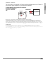
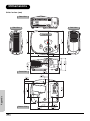
PRODUCT DISPOSAL
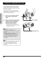
Caution regarding the exhaust of the projector.
Do not put Air Conditioners or
Flowers near the exhaust
vent.
Exhaust Vent
Air Conditioners
or Flowers
Focus
Air flow
Zoom
LENS SHIFT
(V)
LENS SHIFT
(H)
ENTER
Temp led
INPUT
STANDBY
KEYSTONE
MENU
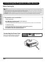
Before using the projector, please read this operation manual carefully.
To facilitate reporting the loss or theft of your Projector, record the Serial Number located on the
bottom of the projector and retain this information. Before recycling the packaging, be sure that you
have checked the contents of the carton thoroughly against the list of “Package Contents” on page 7.
WARRANTY
Promptly register the Projector’s Warranty using the REGISTRATION CARD packed with the
projector. The Warranty assures that you immediately receive the full benefit of the parts, service and
labor warranty applicable to your purchase.
3
PREFACE
This projector utilizes a tin-lead solder, UHP Lamp containing a small amount of mercury. Disposal of
these materials may be regulated due to environmental considerations.
INTRODUCTION
Contents
Preface .............................................................................. 1
Notices .............................................................................. 2
Introduction
Package Contents ............................................................. 7
Features ............................................................................ 8
Components ...................................................................... 9
Projector (Front and Top View) ............................. 9
Projector (Rear View) .......................................... 10
Remote Control ................................................... 11
Using the Remote Control ............................................... 12
Available Range of the Remote Control .............. 12
Inserting the Batteries ......................................... 12
Connections and Setup
Connecting the Projector to Other Devices ..................... 14
Before Setting Up ................................................ 14
Connecting the Power Cord ................................ 14
Connecting to Video Equipment ...................................... 15
Connecting to Video Equipment.......................... 15
Connecting to Component Video Equipment ...... 16
Connecting by Using the DVI Cable.................... 16
Connecting by Using a DVI-D to HDMI Cable..... 17
Connecting the Projector to a Computer ......................... 18
Connecting to a Computer .................................. 18
Connecting the Thumbscrew Cables............................... 19
“Plug and Play” Function ................................................. 19
Using the Adjustment Feet .............................................. 20
Adjusting the Lens ........................................................... 21
Using the Lens Shift ........................................................ 21
Setting up the Screen ...................................................... 22
Screen Size and Projection Distance .................. 23
Projection from behind the screen ...................... 24
Basic Operation
Image Projection ............................................................. 26
Basic Procedure .................................................. 26
Selecting the On-screen Display Language ........ 28
Menu Bar Items ............................................................... 29
Using the Menu Screen ................................................... 31
Menu Selections (Adjustments) .......................... 31
Adjusting the Picture ....................................................... 32
Adjusting Image Preferences .............................. 32
Color Type Mode................................................. 34
Adjusting Computer Images ............................................ 37
4
Easy to Use Functions
INTRODUCTION
Selecting the Picture Display Mode................................. 40
H-V Position Function...................................................... 43
White Enhance ................................................................ 45
Selecting the Economy Mode.......................................... 45
Setting the Power Save....................................... 45
Automatic Power Off Function......................................... 46
Source Select .................................................................. 46
OSD Timeout................................................................... 47
Setting a Background Image ........................................... 47
Selecting a Background Image ........................... 47
OSD Blending.................................................................. 48
Reversing/Inverting Projected Images............................. 48
Setting the Projection Mode ................................ 48
Deinterlace ...................................................................... 49
Reset ............................................................................... 50
Lamp Timer Reset ........................................................... 50
Status Screen .................................................................. 51
Factory reset ................................................................... 51
Appendix
Maintenance .................................................................... 54
Cleaning the Ventilative Holes ........................................ 55
Cleaning the Ventilative Holes ............................ 55
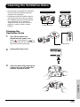
About the Lamp ............................................................... 56
Caution Concerning the Lamp ............................ 56
Replacing the Lamp ............................................ 56
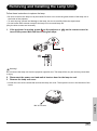
Removing and Installing the Lamp Unit........................... 57
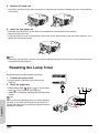
Resetting the Lamp Timer ............................................... 58
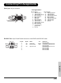
Connecting Pin Assignments .......................................... 59
Computer Compatibility Chart ......................................... 60
Video Compatibility Chart ................................................ 61
Troubleshooting............................................................... 61
Product Specifications ..................................................... 63
Dimensions...................................................................... 64
5
INTRODUCTION
Introduction
6
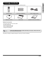
Package Contents
INTRODUCTION
Open the package and ensure that you have the following items:
COMPONENT 1
COMPONENT 2
VIDEO/S-VIDEO
DVI/PC
Remote control
Two “AAA” size batteries
Matte
rho
Quick Guid
e
This manual
Ring cap cover set
may not
be copied
rn DLP
FRONT
PROJEC
TO
Power cord(By country)
User's Ma
nual
R
© All
in any mediarights reserved.
or form
without
the written
consent
of the manufacturer
.
Quick Guide
Operation manual (this manual)
Optional accessories
HD 15-pin VGA to HD 15-pin VGA cable
RS-232C cable (3M)
DVI-D to DVI-D cable (3M)
DVI-D to HDMI cable (3M)
Ceiling mount package
Note
• Some of the cables may not be available depending on the region. Please check with
your nearest Authorized Dealer.
If anything is missing or appears damaged, contact your dealer immediately.
7
INTRODUCTION
Features
• Newly developed 0.63-inch DMD™ chip provides significantly improved optical efficiency and
excellent contrast ratio.
• Newly developed DDR (Double Data Rate) chip eliminates Color Breaking phenomena common
with previous generation DLP™ projectors.
• Use of 250W high-output lamp realizes both high color purity and high brightness. Natural
images made possible by high color reproducibility can be created with high-brightness, powerful expression capabilities.
• Realizes vivid images using the latest image quality circuitry.
• New I/P conversion algorithm enhances the performance of the motion detect I/P conversion.
• Extensive improvements on the jagged edges or slanted lines in moving images.
• New Edge Up-Scaling
• As a result of reducing jagged edges and flickering when up-scaling edges of slanted lines,
even signals not reaching a panel resolution of 480I/P can be projected by converting them to
1024X576 resolution images.
• New Film Mode Function
• 3:2 pull down enhancement for not only 480I and 576I signals, but HDTV 1080I signals as well.
• Color Type
• Color Type that freely adjusts only specific hues of RGBCMY enables easy adjustment of specific locations of an image without affecting other portions of the image.
• Use of a DVI/HDCP terminal enables all processes from input to signal processing and projection to be performed digitally, resulting in the realization of all-digital projection without any
data loss due to analog conversion. This also supports the building of home theaters using
HTPC.
8
Components
INTRODUCTION
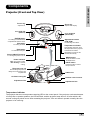
Projector (Front and Top View)
Focus ring
Zoom ring
Adjust focus.
Adjust screen display
Focus
Zoom
Lens shift dial
(Vertical)
ENTER button
For setting the selected items
or adjustments from the menu.
Lens shift dial
(Horizontal)
LENS SHIFT
(V)
LENS SHIFT
ENTER
STATUS
MENU
EXIT
ECO
ECO button
For extended Lamp life.
Power (ON/OFF) buttons
For turning the power on or off.
Power indicator
Blue: The power is ready.
Blue blinking: The fan is
cooling.
Adjustment buttons
(T,S,W,X)
For selecting menu items.
Exit button
For exiting the OSD.
(H)
INPUT
Temperature indicator
This indicator glows red, when
the temperature of the projector
exceeds the set critical
temperature or when the fan
functions abnormally.
MENU button
Press this button to enter
the OSD menus.
INPUT button
Press this button to select
the input source.
Ring cap cover set
Prevent foreign objects from
falling into the focus/zoom ring
compartment.
Air filter/cooling fan
Adjustment foot
Intake vent
Remote control sensor
Adjustment foot
Temperature indicator
The projector has an over temperature warning LED on the control panel. If the projector overheats because
of a dirty filter or another problem, the LED will flash, and the projector lamp will turn off, after which a 90second cooling off period occurs. After restarting the projector, if the unit doesn’t operate normally, take the
projector in for servicing.
9
INTRODUCTION
Projector (Rear View)
Input 3
Video/S-Video
Input 4
DVI/PC
Terminal for connecting video
equipment with an S-video and
Composite Video.
Terminal for Digital Video
Interface, computer and RGB
signals.
VIDEO
Input 1
Component 1
S-VIDEO
Pr/Cr
Pb/Cb
Y
Pr/Cr
Pb/Cb
Y
PC
RS-232
Terminals for component and
YPbPr/YCbCr.
WARNING
•
•
•
•
•
RS-232C terminal
Made in Taiwan
DVI
Input 2
Component 2
Terminals for component YPbPr/
YCbCr.
Do not disassemble any components except the lamp chassis cover while replacing the lamp.
Do not touch ventilation slots, lamp and objects next to them until they have sufficiently cooled down.
Never insert any objects through ventilation holes.
Do not use this unit near water or in a rainy/moist environment.
Keep at least 0.3 foot (10 cm) of space between ventilation slots and nearest object or wall.
AC socket
Firmware upgrade.
Input: 100~240VAC
3.5A,50/60Hz
Air filter/cooling fan
VIDEO
S-VIDEO
Pr/Cr
Remote control sensor
Pb/Cb
Y
Pr/Cr
Pb/Cb
Y
PC
RS-232
WAR
NI
DVI
NG
• Do
• Do not disa
• Nevnot toucsse mbl e
• Do er inse h ven tilatany com
• Keenot usert any objeion slot pon ents
p at this unit cts thros, lam exc ept
leas t
p
0.3 footnea r wat ugh venand objethe lam
(10 cm)er or in tilat ion cts nex p cha ssis
hole t to them cov
of spaa rain y/m
s.
er
Mad e
unti l whil e
ce betw oist
in Taiw
they repl acin
een env iron
hav e
an
g the
ven tilat men
suff icie
lam
ion slott.
ntly p.
coo led
s and
nea rest
dow n.
obje
ct or
wall .
Kensington Security
Standard connector
Exhaust vent
WARNING! As the projector lamp becomes extremely hot, air blowing out from the ventilation
slots can be uncomfortably hot.
Using the Kensington Lock
This projector has a Kensington Security Standard connector for use with a Kensington MicroSaver
Security System. Refer to the information that came with the system for instructions on how to use it to
secure the projector.
10
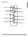
Remote Control
INTRODUCTION
Power (ON/OFF) button
For turning the power on and off.
MENU button
Press this button to enter
the OSD menus.
Adjustment buttons
(T,S,W,X)
For displaying adjustment
and setting screens.
ENTER button
For setting the selected items
or adjustments from the menu.
EXIT button
For Exiting the OSD.
COMPONENT 1
Component 1 button
COMPONENT 2
Press this button to connect
component device sources.
Component 2 button
Press this button to connect
component device sources.
VIDEO/S-VIDEO
VIDEO/S-VIDEO button
DVI/PC
Press this button to connect a standard
RCA video or s-video source.
DVI/PC button
Press this button to connect a
Digital Video Interface device
or computer's VGA source.
Aspect Ratio button
Controls how the projector resizes the
input image.
11
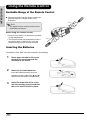
When using the remote control:
45°
23'(7 m)
30°
1
MP
ENT
CO
ON
MP
CO
2
O
/PC
DVI
IDE
/S-V
EO
ENT
VID
ON
Inserting the Batteries
The batteries (two “AAA” size) are included in the package.
1
Press down the tab on the cover
and pull the cover towards the
direction of the arrow.
2
Insert the included batteries.
Insert the batteries making sure the
polarities correctly match the
and
marks inside the battery compartment.
3
12
Insert the lower tab of the cover
into the opening, and press down
the cover until it clicks in place.
30°
30°
O
IDE
/S-V
EO
2
1
T
45°
• The signal from the remote control can be
reflected by the screen.
• Be sure not to drop it, or expose it to moisture
or high temperature.
• The remote control may malfunction under a
fluorescent lamp. If that occurs, move the
projector away from the fluorescent lamp.
T
EN
ON
MP
CO
EN
ON
23'(7 m)
Note
VID
The remote control can be used to control the
projector within the ranges shown in the
illustration.
I/PC
DV
Available Range of the Remote Control
MP
CO
INTRODUCTION
Using the Remote Control
CONNECTIONS AND SETUP
Connections and Setup
13
Connecting the Projector to Other Devices
Before Setting Up
CONNECTIONS AND SETUP
Note
• Before connecting, be sure to turn off both the projector and the devices to be connected. After making
all connections, turn on the projector and then the other devices.
When connecting a computer, be sure that it is the last device to be turned on after all the connections
are made.
• Be sure to read the operation manuals of the devices to be connected before making connections.
This projector can be connected to
Video equipment:
A VCR, Laser disc player or other video equipment.
A DVD player or DTV* decoder.
*DTV is the umbrella term used to describe the new digital television system in the United States.
A computer using:
HD 15-pin VGA to HD 15-pin VGA cable (sold separately optional).
A DVI-D to DVI-D cable (sold separately optional).
A RS-232C cable (sold separately optional).
Connecting the Power Cord
Plug in the supplied power cord into the
AC socket on the rear of the projector.
Supplied
accessory
Power cord
DVI
PC
Y
Pr/Cr
Pb/Cb
Y
Pr/Cr
Pb/Cb
O
S-VIDE
VIDEO
an
2
in Taiw
RS-23
Made
.
.
the lamp d down
coole
cing
repla
iently
suffic
r while
have
sis covethey
chas
until
wall.
lamp them
t or
pt the next to
est objec
ts
ts exce
near
nt.
.
objec
and
onen
onme
holes
slots
comp lamp and
lation /mois t envir
,
lation
le any
semb lation slots gh venti
a rainy een venti
ts throur or in e betw
not disas venti
wate of spac
• Do not touch any objec
t
near
cm)
unit
• Do r inser
this foot (10
• Neve
0.3
not use
• Do
at least
• Keep
WARN
14
ING
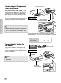
Connecting to Video Equipment
Connecting to Video
Equipment
VCR or other video equipment
To S-video output terminal
Using an S-video or a Composite Video
Cable
To Video output terminal
CONNECTIONS AND SETUP
Using an S-video or a composite video cable,
a VCR, laser disc player or other video
equipment can be connected to INPUT 3 input
terminals.
DVI
PC
Y
Pr/Cr
Pb/Cb
Y
Pr/Cr
Pb/Cb
S-VIDEO
VIDEO
RS-232
Made
in Taiwan
the lamp. down.
replacing ly cooled
while
sufficient
cover
have
they
chassis
until
the lamp to them
or wall.
next
nts except
object
compone and objects
ent.
nearest
n holes. environm
and
ble any slots, lamp
st
n
n slots
ventilatio
not disassem
ventilatio through in a rainy/moi ventilatio
• Do
between
not touch any objects water or
• Do
near
insert
of space
unit
(10 cm)
• Never use this
not
0.3 foot
• Do
at least
• Keep
WAR
NING
Note
• The INPUT 3 (S-VIDEO) terminal uses a
video signal system in which the picture is
separated into color and luminance signals
to realize a higher-quality image. To view a
higher-quality image, use a commercially
available S-video cable to connect the
INPUT 3 terminal on the projector and the
S-video output terminal on the video
equipment.
Composite video cable
(commercially available)
S-video cable
(commercially available)
PC
Pr/Cr
Pr/Cr
Pb/Cb
Pb/Cb
Y
Y
O
S-VIDE
VIDEO
2
RS-23
M ad
Ta iw
e in
an
p.
.
e la m
do wn
in g th co ol ed
pl ac
tly
ile re su ffi ci en
r wh
co ve ey ha ve
th
as si s
ll.
m p ch em un til
la
wa
e
th
or
th
je ct
ce pt s ne xt to
s ex
es t ob
je ct s.
ne nt
ne ar
en t.
d ob
le
m po
ro nm ot s an d
y co
m p an tio n ho
en vi
n sl
e an
s, la
ila
m oi st
ila tio
ve nt
em bl tio n sl ot
ug h
ra in y/ n ve nt
sa ss
ila
no t di uc h ve nt je ct s th ro r or in a be tw ee
• Do
ac e
t to
wa te
y ob
sp
no
ar
an
• Do r in se rt is un it ne 0 cm ) of
ve
(1
e th
fo ot
• Ne
no t us as t 0. 3
le
• Do
ep at
• Ke
ING
N
WAR
15
Connecting to Component
Video Equipment
To analog component
output terminal
Using a Component Cable (INPUT 1 or 2)
DVI
PC
Y
Pr/Cr
Pb/Cb
Y
Pb/Cb
Pr/Cr
S-VIDEO
VIDEO
in Taiwan
Made
the lamp. down.
replacing tly cooled
while
sufficien
cover
have
chassis until they
the lamp to them
or wall.
next
nts except
object
objects
ent.
compone and
nearest
and
n holes. environm
ble any slots, lamp
ist
n slots
n
ventilatio
not disassem
ventilatio through in a rainy/mo ventilatio
• Do
or
between
not touch any objects water
• Do
near
of space
insert
unit
cm)
• Never use this foot (10
not
0.3
• Do
at least
• Keep
RS-232
CONNECTIONS AND SETUP
Use a component cable when connecting to
the INPUT 1 or 2 terminal and component
video equipment such as DVD players and
DTV* decoders.
*DTV is an umbrella term used to describe the
new digital television system in the United
States.
WAR
DVD player or
DTV* decoder
NING
Component cable
(commercially available)
DVI
PC
Pr/Cr
Note
Pr/Cr
S-VIDE
Pb/Cb
Pb/Cb
Y
Y
O
EO
• When connecting the projector to the video
equipment in this way, select “Component 1
or 2” for “Input Source” in the “Main” menu.
RS-232
Ma de
wa
in Tai
n
p.
dow n.
the lam
lac ing ly coo led
ile rep fici ent
er wh
e suf
s cov
y hav
cha ssi
il the
lam p the m unt
ll.
or wa
ept the nex t to
s
s exc
obj ect
.
res t
pon ent and obj ect es.
ent
nea
com
p
hol
and
iro nm
slo ts
ble any slo ts, lam tila tion
ist env
ass em
h ven rai ny/ mo ven tila tion
tion
thr oug
not dis ch ven tila
en
in a
ect s
• Do
bet we
ter or
not tou any obj
r wa of spa ce
ert
• Do
t nea
)
ver ins this uni t (10 cm
• Ne
not use st 0.3 foo
• Do
t lea
N
WAR
ING
The component jack for a DVD and so forth may be
indicated with Y, CB or CR. Connect each jack as shown
below.
Connecting by Using the
DVI Cable
Use the DVI cable when connecting to the
INPUT 4 terminal and video equipment with
the DVI output terminal such as DVD players
and DTV* decoders.
Projector
Y
PB
PR
DVD player or
DTV decoder
Y
CB
CR
Optional
accessory
DVI-D cable
DVD player or
DTV* decoder
DVI
PC
Y
Pr/Cr
Pb/Cb
Y
Pr/Cr
Pb/Cb
S-VIDEO
VIDEO
RS-232
Made
the lamp. down.
replacing ly cooled
while
sufficient
cover
have
they
chassis
until
the lamp to them
or wall.
next
nts except
object
compone and objects
ent.
nearest
n holes. environm
and
ble any slots, lamp
st
n
n slots
ventilatio
not disassem
ventilatio through in a rainy/moi ventilatio
• Do
between
not touch any objects water or
• Do
near
insert
of space
unit
(10 cm)
• Never use this
not
0.3 foot
• Do
at least
• Keep
Note
WAR
NING
• Select the input signal type of the video
equipment.
DVI-D cable
(sold separately)
DVI
PC
Pr/Cr
Pb/Cb
Y
an
Taiw
e in
Mad
.
lamp
dow n.
g the cool ed
acin
tly
e repl icien
r whilhave suff
sis cove
they
wall .
chas
unti l
ct or
obje
to them
rest
nt. and nea
viro nme
slots
n
ilatio
16
in Taiwan
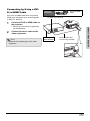
Connecting by Using a DVID to HDMI Cable
Use a DVI to HDMI cable when connecting
HDMI video equipment such as DVD players
to INPUT 4 terminal.
1
Optional
accessory
DVI-D to HDMI
cable
To HDMI output terminal
Connect a DVI-D to HDMI cable to
the projector.
DVI
PC
Y
Pr/Cr
Pb/Cb
Y
Pr/Cr
• Secure the connectors by tightening
the thumbscrews.
RS-232
Made
WAR
NING
in Taiwan
the lamp. down.
replacing ly cooled
while
sufficient
cover
have
they
chassis
until
the lamp to them
or wall.
next
nts except
object
compone and objects
ent.
nearest
lamp
n holes. environm
and
ble any
n slots
CONNECTIONS AND SETUP
2
Pb/Cb
S-VIDEO
VIDEO
st
n slots,
ventilatio
not disassem
ventilatio through in a rainy/moi ventilatio
• Do
between
not touch any objects water or
• Do
near
insert
of space
unit
(10 cm)
• Never use this
not
0.3 foot
• Do
at least
• Keep
Connect the above cable to the
video equipment.
Note
DVD player or
DTV* decoder
DVI-D to HDMI cable
(commercially available)
• Select the input signal type of the video
equipment.
DVI
PC
Pr/Cr
Pb/Cb
Y
an
Taiw
e in
Mad
.
lamp
dow n.
g the cool ed
acin
tly
e repl icien
r whilhave suff
sis cove
they
wall .
unti l
p chas
ct or
obje
t to them
rest
ent. and nea
slots
nvir onm
tilat ion
17
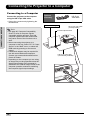
Connecting the Projector to a Computer
Connecting to a Computer
Connect the projector to the computer
using the HD 15-pin VGA cable.
Optional
accessory
HD 15-pin
VGA cable
• Secure the connectors by tightening the
thumbscrews.
CONNECTIONS AND SETUP
Notebook Computer
Note
HD 15-pin VGA cable
(sold separately)
To VGA output terminal
• See page 60 “Computer Compatibility
Chart” for a list of computer signals
compatible with the projector. Use with
computer signals other than those listed
may cause some of the functions not to
work.
• When connecting the projector to a
computer in this way, select “PC” for “Input
Source” in the “Main” menu, or select the
RGB mode by pressing on the remote
control.
• A Macintosh adaptor may be required for
use with some Macintosh computers.
Contact your nearest Authorized Service
Center or Dealer.
• Depending on the computer you are using,
an image may not be projected unless the
signal output setting of the computer is
switched to the external output. Refer to the
computer operation manual for switching
the computer signal output settings.
DVI
PC
Y
Pr/Cr
Pb/Cb
RS-232
Made
in Taiwan
the lamp. down.
replacing ly cooled
while
sufficient
cover
have
they
chassis
until
the lamp to them
or wall.
next
nts except
object
compone and objects
ent.
nearest
n holes. environm
and
ble any slots, lamp
st
n
n slots
ventilatio
not disassem
ventilatio through in a rainy/moi ventilatio
• Do
between
not touch any objects water or
• Do
near
insert
of space
unit
• Never use this foot (10 cm)
not
0.3
• Do
at least
• Keep
WAR
NING
HD 15-pin VGA cable
(commercially available)
DVI
PC
Pr/Cr
Pb/Cb
Y
Ma de
iwa
in Ta
n
p.
.
the lamole d do wn
co
lac ing
ile rep ffic ien tly
ve r wh ve su
sis co the y ha
ch as
til
m un
wa ll.
to the
t or
ob jec
st
are
me nt.
d ne
vir on slo ts an
n
ila tio
18
Pb/Cb
Y
Pr/Cr
S-VIDEO
VIDEO
Connect the projector to the computer
using the DVI-D cable (sold separately).
Note
• Select the input signal type of the video
equipment.
Optional
accessory
DVI-D cable
To DVI Digital output terminal
Desktop Computer
CONNECTIONS AND SETUP
DVI
PC
Y
Pr/Cr
Pb/Cb
Y
Pr/Cr
Pb/Cb
S-VIDEO
VIDEO
RS-232
Made
in Taiwan
the lamp. down.
replacing ly cooled
while
sufficient
cover
have
they
chassis
until
the lamp to them
or wall.
next
nts except
object
compone and objects
ent.
nearest
n holes. environm
and
ble any slots, lamp
st
n
n slots
ventilatio
not disassem
ventilatio through in a rainy/moi ventilatio
• Do
between
not touch any objects water or
• Do
near
insert
of space
unit
(10 cm)
• Never use this
not
0.3 foot
• Do
at least
• Keep
WAR
NING
DVI-D cable
(sold separately)
DVI
PC
Pr/Cr
Pb/Cb
Y
Y
an
Taiw
e in
Mad
lam p. dow n.
g the coo led
repl acin
icie ntly
whi le e suff
hav
cov er
they
ssis
wal l.
unti l
p cha
ct or
obje
the lamt to them
rest
nex
t.
nea
ects s.
men
and
hole env iron slot s
moi stven tilat ion
wee n
Connecting the Thumbscrew Cables
Connect the thumbscrew cable making sure that it fits correctly into the
terminal. Then, firmly secure the connectors by tightening the screws on
both sides of the plug.
Do not remove the ferrite core attached to the HD 15-pin VGA cable.
DVI
PC
Pr/Cr
Pb/Cb
Y
Mad e
in Taiw
an
.
the lamped dow n.
acin g
tly cool
e repl
r whil
suffi cien
have
sis cove
they
mp chas
until
them
wall .
xt to
ct or
est obje
ent.
near
envi ronm slots and
ntila tion
“Plug and Play” Function
Ferrite core
This projector is compatible with VESA-standard DDC 1/DDC 2B. The projector and a VESA DDC
compatible computer will communicate their setting requirements, allowing for quick and easy setup.
Before using the “Plug and Play” function, be sure to turn on the projector first and the connected
computer last.
Note
• The DDC “Plug and Play” function of this projector operates only when used in conjunction with a VESA
DDC compatible computer.
19
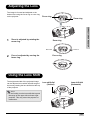
Using the Adjustment Feet
The height of the projector can be adjusted
using the adjustment feet when the surface
the projector is placed on is uneven or when
the screen is slanted.
CONNECTIONS AND SETUP
The projection of the image can be made
higher by adjusting the projector when it is in a
location lower than the screen.
1
Press the foot releases and lift
the projector to the desired
angle.
2
Remove your hands from the foot
releases. Once the adjustment
feet have locked in position,
place the projector down.
Foot releases
• If the screen is at an angle, the
adjustment feet can be used to adjust
the angle of the image.
Note
• The projector is adjustable up to
approximately 5 degrees from the standard
position.
• When the height of the projector is adjusted,
the image may become distorted
(keystoned), depending on the relative
positions of the projector and the screen.
See page 44 for details on keystone
correction.
Info
• When lowering the projector, be careful not
to get your finger caught in the area
between the adjustment foot and the
projector.
20
Adjustment feet
Adjusting the Lens
The image is focused and adjusted to the
desired size using the focus ring or zoom ring
on the projector.
Focus ring
Focus
Zoom
Zoom is adjusted by rotating the
zoom ring.
Zoom ring
Zoom in
Zoom out
2
Focus is adjusted by moving the
focus ring.
CONNECTIONS AND SETUP
1
Zoom ring
Focus ring
Using the Lens Shift
The height and width of the projected image
can be adjusted to be within the shift range of
the lens by rotating the lens shift dial at the top
of the projector.
Lens shift dial
(Vertical)
Lens shift dial
(Horizontal)
Note
• Do not forcibly turn the lens shift dial beyond
the range of the upper left and lower right
positions. This may cause the projector to
malfunction.
21
Setting up the Screen
Position the projector perpendicular to the screen with all feet flat and level to achieve an optimal image.
• The projector lens should be centered in the middle of the screen. If the horizontal line passing through
the lens center is not perpendicular to the screen, the image will be distorted, making viewing difficult.
• For an optimal image, position the screen so that it is not in direct sunlight or room light. Light falling
directly on the screen washes out the colors, making viewing difficult. Close the curtains and dim the
lights when setting up the screen in a sunny or bright room.
• A polarizing screen cannot be used with this projector.
Standard Setup (Front Projection)
Place the projector at the required distance from the screen
according to the desired picture size. (See page 23)
An Example of Standard Setup
• The distance from the screen to the projector may
vary depending on the size of the screen.
Side View
• The default setting can be used, when placing the
projector in front of the screen. If the projected
image is reversed or inverted, readjust the setting to
“Front” for “PRJ Mode” in the “Options” menu.
90
Audience
Top View
Focus
(V)
STANDBY
KEYSTONE
ENTER
Temp led
MENU
INPUT
Zoom
LENS SHIFT
(H)
90
• Place the projector so that an imaginary horizontal
line that passes through the center of the lens is
perpendicular to the screen.
LENS SHIFT
CONNECTIONS AND SETUP
Note
3
H
40
3
H
40
Note
1
V
2
H
V
1
V
2
1
H
2
22
1
V
2
2D Lens Shift Ability:
• The vertical display (Biggest) is ±1/2 screen.
(±100%)
• The horizontal display (Biggest) is ±3/40
screen. (±15%)
• It is recommended that images be projected
onto the dashed line octagonal area for fine
image quality.
• There is a tolerance of ±3% in the formula
above.
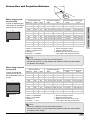
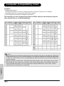
Screen Size and Projection Distance x
z
When using a wide
screen (16:9)
16
9
: Picture area
Diagonal
300”
250”
200”
150”
133”
106”
100”
92”
84”
72”
60”
40”
Wide
261”
218”
174”
131”
116”
92”
87”
80”
73”
63”
52”
35”
Hight
147”
123”
98”
74”
65”
52”
49”
45”
41”
35”
29”
20”
Projection Distance
Max
37’2” (11.3 m)
31’ (9.4 m)
24’9” (7.6 m)
18’7” (5.7 m)
16’6” (5.0 m)
13’2” (4.0 m)
12’5” (3.8 m)
11’5” (3.5 m)
10’5” (3.2 m)
8’11” (2.7 m)
7’5” (2.3 m)
4’11” (1.5 m)
Min
29’8” (9.0 m)
24’8” (7.5 m)
19’9” (6.0 m)
14’1” (4.5 m)
13’2” (4.0 m)
10’6” (3.2 m)
9’11” (3.0 m)
9’1” (2.8 m)
8’4” (2.5 m)
7’11” (2.2 m)
5’11” (1.8 m)
3’11” (1.2 m)
Distance from Lens center to
the lower edge of the image
upper
lower
0” (0 cm)
-12’3” (-374 cm)
0” (0 cm)
-10’3” (-311 cm)
0” (0 cm)
-8’2” (-249 cm)
0” (0 cm)
-6’2” (-187 cm)
0” (0 cm)
-5’5” (-166 cm)
0” (0 cm)
-4’4” (-132 cm)
0” (0 cm)
-4’1” (-125 cm)
0” (0 cm)
-3’9” (-115 cm)
0” (0 cm)
-3’5” (-105 cm)
0” (0 cm)
-2’11” (-90 cm)
0” (0 cm)
-2’5” (-75 cm)
0” (0 cm)
-1’8” (-50 cm)
The formula for screen size and projection distance
y1 (Max.) = 0.037767459x
y2 (Min.) = 0.0301077047x
z1 (Upper) = 0
z2 (Lower) = –1.245264x
x : Screen size (diag.) (meter)
y : Projection distance (feet)
z : Distance from the lens center to the
lower edge of the image (centimeter)
Note
• There is a tolerance of ±3% in the formula above.
• Values with a minus (–) sign indicate the distance of the lens center below
the bottom of the image.
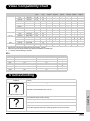
When using a normal
screen (4:3)
In case of setting the
16:9 picture to the full
horizontal width of the 4:3
screen.
4
3
: Screen area
: Picture area
Screen Size (4:3)
Diagonal
250”
200”
150”
133”
106”
100”
92”
84”
72”
60”
40”
Wide
200”
160”
120”
106”
85”
80”
74”
67”
58”
48”
32”
Hight
150”
120”
90”
80”
64”
60”
55”
50”
43”
36”
24”
Projection Distance
Max
28’5” (8.7 m)
22’9” (6.9 m)
17’1” (5.2 m)
15’2” (4.6 m)
12’1” (3.7 m)
11’4” (3.5 m)
10’6” (3.2 m)
9’7” (2.9 m)
8’2” (2.5 m)
6’10” (2.1 m)
4’7” (1.4 m)
Min
22’8” (6.9 m)
18’2” (5.5 m)
13’7” (4.1 m)
12’1” (3.7 m)
9’7” (2.9 m)
9’1” (2.8 m)
8’4” (2.5 m)
7’7” (2.3 m)
6’6” (2.0 m)
5’5” (1.7 m)
3’8” (1.1 m)
Distance from Lens center to
the lower edge of the image
upper
lower
0” (0 cm)
-9’5” (-286 cm)
0” (0 cm)
-7’6” (-229 cm)
0” (0 cm)
-5’8” (-171 cm)
0” (0 cm)
-5’0” (-152 cm)
0” (0 cm)
-4’0” (-121 cm)
0” (0 cm)
-3’9” (-114 cm)
0” (0 cm)
-3’5” (-105 cm)
0” (0 cm)
-3’2” (-96 cm)
0” (0 cm)
-2’8” (-82 cm)
0” (0 cm)
-2’3” (-69 cm)
0” (0 cm)
-1’6” (-46 cm)
The formula for screen size and projection distance
y1 (Max.) = 0.03466592x
y2 (Min.) = 0.0276352x
z1 (Upper) = 0
z2 (Lower) = -1.143x
x : Screen size (diag.) (meter)
y : Projection distance (feet)
z : Distance from the lens center to the
lower edge of the image (centimeter)
Note
• There is a tolerance of ±3% in the formula above.
• Values with a minus (–) sign indicate the distance of the lens center below
the bottom of the image.
23
CONNECTIONS AND SETUP
In case of displaying the
16:9 picture on the whole
area of the 16:9 screen.
Screen Size (16:9)
y
Projection from behind the screen
Projecting a Reversed/Inverted Image
CONNECTIONS AND SETUP
Place a translucent screen between the projector and the When using the default setting.
audience.
TOn-screen Display
Reverse the image by setting “Rear” for “PRJ Mode” in the
“Options” menu.
Projection using a mirror
The image is reversed.
Place a mirror (normal flat type) in front of the lens.
When using the default setting.
Reverse the image by setting “Rear” for “PRJ Mode” in the TOn-screen Display
“Options” menu, when the mirror is placed on the side
where the audience is.
The image is reversed.
Info
• When using a mirror, be sure to carefully position
both the projector and the mirror so that the light
does not shine into the eyes of the audience.
Ceiling-mount setup
It is recommended that you use the optional ceilingmount bracket for this installation.
Before mounting the projector, contact your nearest
Authorized Service Center or Dealer to obtain the
recommended ceiling-mount bracket (sold separately).
Be sure to adjust the position of the projector to match
the distance (Z) from the lens center position to the
lower edge of the image, when mounting the projector
on the ceiling.
Invert the image by setting “Ceiling + Front” for “PRJ
Mode” in the “Options” menu.
When using the default setting.
TOn-screen Display
The image is reversed.
24
Basic Operation
Basic Operation
25
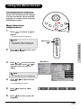
Image Projection
Basic Procedure
Connect the required external equipment to
the projector before operating the following
procedures.
Info
• The language preset at the factory is
English. If you want to change the onscreen display to another language, reset
the language according to the procedure on
page 28.
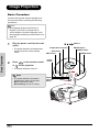
1
Plug the power cord into the wall
outlet.
Basic Operation
• The power indicator illuminates blue,
and the projector enters standby
mode.
2
Press
or
on the remote control
T, S, W, X buttons
Temperature Indicator
ENTER button
INPUT button
ECO button
MENU button
EXIT button
Power
button
on the projector.
ENTER
• The power indicator turns off.
STATUS
Note
• The power indicator illuminates,
indicating the status of the lamp.
Blue: The power is ready.
Blue blinking: The fan is cooling.
26
MENU
EXIT
Power
indicator
(Blue)
ECO
INPUT
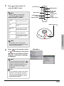
3
Press
on the projector to
INPUT
select the INPUT mode.
Note
Power button
MENU button
T, S, W, X
buttons
EXIT button
COMPONENT 1
• When a signal is not received,
“Searching” will be displayed.
About the INPUT modes
S-Video
Use this option to select
the S-Video input source.
Video
Use this option to select
the composite video input
source.
Use this option to select a
YPbPr, SDTV, or HDTV
component input source.
DVI
Use this option to select
the DVI input source.
PC
Use this option to select
the computer as an input
source.
Component 1
button
Video/
S-Video button
COMPONENT 2
VIDEO/S-VIDEO
DVI/PC
INPUT button
INPUT
ENTER
STATUS
MENU
EXIT
ECO
Basic Operation
Component
1&2
Component 2
button
DVI/PC button
INPUT
Note
• If you select “Auto” as the input
source, then the correct input source
is selected automatically.
4
Press
or
on the remote control
Main Menu
on the projector, then press
Enter to turn off the projector,
when the confirmation message
is displayed.
Note
• If you accidentally press power
and do not want to turn off the
projector, press Exit button or wait
until the confirmation message
disappears.
Info
• Do not unplug the power cord during
projection or cooling fan operation.
This can cause damage due to the
rise in internal temperature, as the
cooling fan also stops.
27
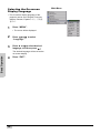
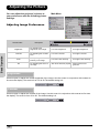
Selecting the On-screen
Display Language
• The on-screen display language of the
projector can be set to English, Français,
Italiano, Deutsch, Español, 中文 , 日本語 ,
한국어 .
1
Press “MENU”.
2
Press
or X to select
“Language”.
3
Press S or T to select desired
language, and then press
.
• The menu will be displayed.
Basic Operation
The desired language will be set as the
on-screen display.
4
28
Press “EXIT”.
Main Menu
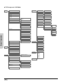
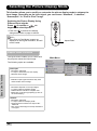
Menu Bar Items
This list shows the items that can be set in the projector.
Composite Video/S-Video, DVI Mode
Picture
Brightness
Options
-50 ~ +50
White Enhance
ON/OFF
Contrast
-50 ~ +50
ECO mode
ON/OFF
Color
-64 ~ +64 (DVI hide)
Auto Power Off
ON/OFF
Tint
-64 ~ +64 (DVI hide)
Source Select
Manual/Auto
Sharpness
Softest, Soft, Normal, Sharp,
Sharpest
OSD Timeout
5. 15. 60 secs
Gamma
1.0/1.5/1.8/2.0/2.2/2.35/2.5/2.8
Background
Blue, Black
Color Temp
Color Temp 5000k ~ 10000k,
Native
OSD Blending
ON/OFF
x
-30 ~ +30
PRJ Mode
Front/Front ceiling/
Rear/Rear ceiling
y
-30 ~ +30
Deinterlace
(Dvi Hide)
DCTI
0~7
Video on film
ON/OFF
Film Mode
3:2@60Hz
Reset this CT
Standard/Custom1/Custom2/
Custom3
Color Type
Target Color (B/C/G/Y/R/M)
-64 ~ +63
Saturation
-64 ~ 0
Tint
-64 ~ +64
2:2@50Hz
2:2@50Hz
3:2@60Hz
OFF
Reset
Reset (This color)
Lamp Timer Reset
Reset (All color)
Picture Setting
Status
Normal/Bright/Movie/Custom1/
Custom2
Input Source
Save this setting
S-Video
Composite
Reset
Layout
Basic Operation
Lightness
Aspect Ratio (720p, 1080i, Hide)
H-Position
(DVI Hide) -16 ~ +16
V-Position
(DVI Hide) -16 ~ +16
Component 1
Standard/Anamorphic/
Letterbox/Pixel to Pixel
Component 2
DVI
V-Keystone -128 ~ +127
(1080i Hide)
PC
Vertical Keystone
Language
Horizontal Keystone
H-Keystone -128 ~ +127
(1080i Hide)
Vertical Keystone
Horizontal Keystone
Reset
English
Français
Italiano
Deutsch
Español
中文
日本語
한국어
Factory Reset
29
PC/Component 1&2 Mode
Picture
Brightness
-50 ~ +50
White Enhance
ON/OFF
Contrast
-50 ~ +50
Options
ECO mode
ON/OFF
Color
(PC Hide)
-64~+64
Auto Power Off
ON/OFF
Tint
(PC Hide)
-64~+64
Source Select
Manual/Auto
OSD Timeout
5. 15. 60 secs
Background
Blue, Black
OSD Blending
ON/OFF
PRJ Mode
Front/Front ceiling/
Rear/Rear ceiling
Deinterlace
(1080i, PC Hide)
DCTI
0~7
Reset this CT
Video on film
ON/OFF
Standard/Custom1/Custom2/
Custom3
Film Mode
3:2@60Hz
Softest, Soft, Normal, Sharp,
Sharpest
Sharpness
Gamma
1.0/1.5/1.8/2.0/2.2/2.35/2.5/2.8
Color Temp
Color Temp 5000k ~ 10000k,
Native
Color Type
x
-30 ~ +30
y
-30 ~ +30
2:2@50Hz
Basic Operation
Target Color (B/C/G/Y/R/M)
Lightness
-64 ~ +63
Saturation
-64 ~ 0
Tint
-64 ~ +64
2:2@50Hz
3:2@60Hz
OFF
Reset
Reset (This color)
Lamp Timer Reset
Reset (All color)
Picture Setting
Fine Sync
Normal/Bright/Movie/Custom1/
Custom2
Status
Input Source
Save this setting
Composite
Reset
Component 1
Clock
-50 ~ +50
(Component 1/2 Hide)
Component 2
Phase
DVI
-16 ~ +15
Reset
PC
Execute Auto Tune
Language
Auto Tune (ON/OFF)
Layout
Aspect Ratio (720p, 1080i, Hide)
H-Position
-16 ~ +16
V-Position
-16 ~ +16
V-Keystone -128 ~ +127
(1080i Hide)
Standard/Anamorphic/
Letterbox/Pixel to pixel
Factory Reset
Vertical Keystone
Horizontal Keystone
H-Keystone -128 ~ +127
(1080i Hide)
Vertical Keystone
Horizontal Keystone
Reset
30
S-Video
English
Français
Italiano
Deutsch
Español
中文
日本語
한국어
Using the Menu Screen
This projector has one set of menu
screens that allow you to adjust the
image and various projector settings.
You can operate the menus from the
projector or remote control using the
following procedure.
ENTER
STATUS
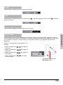
Menu Selections
(Adjustments)
1
Press
MENU
EXIT
ECO
on remote or
INPUT
MENU button
on
MENU
MENU
keypad.
• The menu screen is displayed.
Note
MENU button
• The “Picture” menu screen for the
selected input mode is displayed.
Basic Operation
COMPONENT 1
2
Press S or T to select the menu
you want to adjust.
COMPONENT 2
VIDEO/S-VIDEO
DVI/PC
3
Press X or
to reach the Submenu and then press S or T to
select the item you want to
adjust.
Main Menu
Note
• The selected item will be highlighted.
4
Press W or X to adjust the item
selected.
• The adjustment is stored.
5
6
Press
to return to “Main
MENU”.
Press , the menu screen will
disappear.
31
Adjusting the Picture
You can adjust the projector's picture to
your preferences with the following picture
settings.
Main Menu
Adjusting Image Preferences
Selected item
Brightness
Basic Operation
Contrast
Color
Tint
Description
For adjusting the
brightness of an image
For lower brightness
For higher brightness
For adjusting the contrast
level
For lower contrast
For higher contrast
For adjusting the color
intensity of an image
For lower color intensity
For higher color intensity
For adjusting the tones of
an image
Skin tones become purplish
Skin tones become
greenish
Brightness
Use this option to adjust the overall brightness of the image. Use this control in conjunction with contrast to
fine-tune the display. The scale is from -50 to 50.The default setting is 0.
Contrast
Use this option to adjust the contrast of the image. Use this control in conjunction with contrast to fine-tune
the display. The scale is from -50 to 50. The default setting is 0.
32
Color
Use this option to adjust the color intensity of the image.
Tint
Use this option to adjust the tint of your image. Press X to make the image more green. Press W to make the
image more purple.
Sharpness
Use this option to adjust the clarity and focus of the image.
Color TEMP
Select x, y to adjust the color temperature. For
example:
• When you adjust the x, X, y,W, the image will
looks red.
• When you adjust the x,W, y,W, the image will
looks blue.
• When you adjust the x,W, y,X, the image will
looks green.
• When you adjust the x, X, y, X, the image
will looks yellow.
The point will move in the
Black Body Curve.
33
Basic Operation
Use this option to set the color temperature of the image. Higher color temperatures make the image look
cool with a bluish hue. Lower color temperature make the image look warmer with a reddish hue. The range
is from 5000°K to 10000°K. The step is 500°K. When sets to "NATIVE", the image has the maximum
brightness.
Gamma
Use this option to adjust the gamma correction of the image. Default setting is 2.2. Gamma correction
provides seven non-linear gamma corrections 1.0, 1.5, 1.8, 2.0, 2.2, 2.35, 2.5, and 2.8.
Color Type
This function allows you to individually adjust the display characteristics of six colors (R:Red, Y:Yellow,
G:Green, C:Cyan, B:Blue, M:Magenta).
Color Type Mode
Basic Operation
Select “Color Type” from the picture
menu on the menu screen,and then
press "Enter".
For operating the menu screen, see
page 31.
Selected item
Description
Standard
Default setting
Custom 1-3
“Lightness”, “Saturation”, and “Tint” can be
adjusted for each of
the six colors.
Target color
Select “Target color” from the “Color
Type"menu.
34
Blue
Cyan
Green
Yellow
Red
Magenta
Lightness
Select “Lightness” from the “Color
Type”menu.
Saturation
Select “Saturation” from the “Color Type”
menu.
Tint
Select “Tint” from the “Color Type” menu.
Basic Operation
Resetting User-Defined Color Settings
Select “Reset (This Color)” or “Reset (All Colors)” from the “Color Type” menu on the
menu screen.
For operating the menu screen, see page 31.
Selected item
Description
Reset (This color)
“Lightness”
“Saturation” and
“Tint” of the color
selected for “Target”
are reset.
Reset (All colors)
“Lightness”
“Saturation” and
“Tint” of all colors are
reset.
35
Picture setting
Basic Operation
This function stores Brightness, Contrast,
Color, Tint, Sharpness, Gamma, Color Temp,
Color Type, and White Enhance set in
“Picture”. Each stored setting is reassigned to
each input mode.
Normal
Bright
Movie
Brightness
0
5
-10
Contrast
0
10
8
Sharpness
Normal
Normal
Normal
Color
0
0
0
Tint
0
0
0
Gamma
Gamma2.2
Gamma 1.8
Gamma2.2
Color Temp
8000K
7500K
6500K
Color Type
Standard
Standard
Standard
White Enhance
ON
ON
OFF
Custom 1-2
"Brightness", "contrast", "color", "tint",
"sharpness", "gamma", "color temp",
"color type" and "white enhance" of the
color selected for “Target” are reset.
Select “Picture Setting” from the “Picture” menu on the menu screen.
For operating the menu screen, see page 31.
Note
• When Recalling Saved Contents:
When a saved memory number is selected,
the contents of the “Picture” menu change
to the adjustment values of the saved
memory number.
• When Editing Saved Contents:
Edit the contents of the “Picture” menu after
selecting the Memory number for which
adjustment values are to be edited.
Save this setting
Use this option to save changes you made in “Picture setting” to custom 1 or custom 2.
Reset
Select this option to set to all items in the "Picture" menu to the factory default values.
36
Adjusting Computer Images
(Computer Source Signal Only)
Use the Fine Sync function in case of irregularities such as vertical stripes or flickering in
portions of the screen.
When Auto Tune is OFF
When “Auto Tune” is “OFF”,
interference such as flickering or
vertical stripes may occur when
displaying tilings or vertical stripes.
Should this occur, adjust “Clock” and
“Phase”, for obtaining an optimum
image.
Main Menu
Selected item
Description
Clock
Adjusts vertical noise.
Phase
Adjusts horizontal
noise (similar to
tracking on your
VCR).
Basic Operation
Select “Clock”, “Phase”, in the “Fine
Sync” menu on the menu screen.
For operating the menu screen, see
page 31.
Auto Tune adjustment
Used to automatically adjust a
computer image.
Screen display during Auto Tune
Select “Execute Auto Tune” from the
“Fine Sync” menu on the menu
screen.
For operating the menu screen, see
page 31.
Note
• Auto Tune adjustment may take some time
to complete, depending on the image stored
in the computer connected to the projector.
37
Basic Operation
NOTES
38
Easy to Use Functions
Easy to Use Functions
39
Selecting the Picture Display Mode
This function allows you to modify or customize the picture display mode to enhance the
input image. Depending on the input signal, you can choose “Standard”, “LetterBox”,
“Anamorphic” or “Pixel to Pixel” image.
Switching the Picture Display Using
Different input signals
Press
on remote or
keypad and select layout.
on
• Each time
is pressed, the display
changes as shown on page 41 and 42.
COMPONENT 1
COMPONENT 2
Info
• In the Pixel to Pixel Mode, images are
displayed in the original resolution, and will
not be scaled.
VIDEO/S-VIDEO
DVI/PC
Aspect Ratio
Aspect Ratio Function
The layout menu enables you to control how
the projector resizes the input image.
The following option are available:
Easy to Use Functions
Anamorphic
• Resolution 1024x576
• 4:3 input is stretched to fit 16:9 display
• Stretches entire image.
Pixel to Pixel
• Maintains input signal resolution. May have
black borders around image.
Standard
• Resolution depends on the Input Signal
• 4:3 input scaled to fit display height
• Width scaled to maintain 4:3 aspect ratio
• Black bars on left and right (taking up 25% of
the whole display)
LetterBox
• Resolution 1024x576
• 4:3 input scaled to fit display width
• Height scaled to maintain 4:3 aspect ratio:
1024x768
• 25% of the entire image on the top and bottom
is cropped.
40
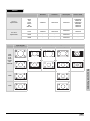
Main Menu
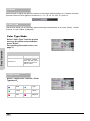
VIDEO
Standard
For 4:3
aspect ratio
For 16:9
aspect ratio
Input Signal
480I
480P
576I
576P
NTSC
PAL
SECAM
Letterbox
Anamorphic
Pixel to Pixel
480i
480P
576i
576P
NTSC
PAL
SECAM
768X576
1024X576
1024X576
640X480i
640X480P
768X576i
768X576P
640X480
768X576
768X576
480P
576P
768X576
768X576
1024X576
1024X576
1024X576
720X480
720X576
720P
-
-
1024X576
-
1080i
-
-
1024X576
-
Output screen image
Standard
Letterbox
Anamorphic
Pixel to Pixel
For 4:3 aspect ratio
Easy to Use Functions
Letter box image
1080I
For 16:9 aspect ratio
720P
41
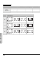
COMPUTER
For 4:3
aspect ratio
Standard
Anamorphic
Pixel to Pixel
VGA(640X480)
768X576
1024X576
640X480
SVGA(800X600)
768X576
1024X576
800X600
XGA(1024X768)
768X576
1024X576
1024X768
.
Input Signal
VGA
For 4:3 aspect ratio
(640x480)
SVGA
For 4:3 aspect ratio
(800x600)
XGA
Easy to Use Functions
For 4:3 aspect ratio
(1024x768)
42
Output screen image
Standard
Anamorphic
Pixel to Pixel
H-V Position Function
This function enables you to center
the display vertically and horizontally.
1
Press “W” or “X” of the
H Position, the display will move
to the left or the right.
2
Press “W” or “X” of the
V Position, the display will move
upward or downward.
Main Menu
Main Menu
Easy to Use Functions
43
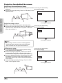
H-V Keystone Function
Correcting Trapezoidal Distortion and
Adjusting Vertical Size of the picture.
Main Menu
This function allows for Keystone correction.
Note
• When the image is projected either from top
or from bottom toward the screen at an
angle, the image becomes distorted
trapezoidally.
The function for correcting trapezoidal
distortion is called Keystone Correction.
• The Keystone Correction can be adjusted
up to angle of approximately ±15 degrees.
• “KEYSTONE” does not work with the 1080I
input signal.
(On-screen Trapezoidal Distortion)
Normal screen
Keystone Correction screen
* Vertical size
adjustment screen
Correction and the adjustment of the vertical
size of the picture.
Easy to Use Functions
1
2
Select “V-Keystone” or
“H-Keystone” in the layout.
Selected item
Description
H Keystone
Horizontally adjusts the
keystone settings.
V Keystone
Vertically adjusts the
keystone settings.
Press“W” or “X” to adjust the
keystone correction.
Compresses
upper side.
* “V-SIZE” is not displayed when the value
of “KEYSTONE” is “0”.
Compresses
lower side.
Horizontal Keystone Correction
Note
• Since the trapezoidal distortion of the image
can be corrected up to an angle of
approximately ±15 degrees, the actual
screen can be diagonally set up to that
angle as well.
• Straight lines or the edges of images may
appear jagged while adjusting the image.
Vertical Keystone Correction
44
White Enhance
Use this option to adjust: the color: white
bright or dark.
Main Menu
Note
• ON
Emphasizes the bright portions of images.
• OFF
Disables “White Enhance”.
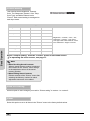
Selecting the Economy Mode
These functions allow you to reduce the power consumption of the projector.
Setting the Power Save
Select “ON” from the “Economy
Mode” under the “Options” menu on
the menu screen.
For operating the menu screen, See
page 31.
ENTER
STATUS
Easy to Use Functions
MENU
EXIT
ECO
INPUT
Note
• Although noise is reduced when “ECO” is
set to “ON”, brightness decreases by 20%.
• “ECO” mode is factory preset to “OFF”.
Status
Brightness
ECO Mode
Main Menu
Power
consumption
ON
(Low power
mode)
80%
270W@110V
OFF
(Standard
mode)
100%
340W@110V
45
Automatic Power Off Function
When an input signal is not detected or you
don't press any input button on Keypad or
remote for more than 15 minutes, the
projector will automatically turn off if set to
“ON”.
Main Menu
Auto Power Off function will be disabled when
it is set to “OFF”.
Select “Auto Power Off” from the
“Options” menu on the menu screen.
For operating the menu screen, see
page 31.
Note
• When the Auto Power Off function is set to
“ON”, 5 minutes before the power turns off,
the message “Power OFF in 5 min.” will
appear on the screen to indicate the
remaining minutes.
Easy to Use Functions
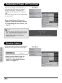
Source Select
Used to select the input source automatically
when there is no signal in the current input.
Source Select
Auto
Manual
Select “source select” from the
“Options” menu on the menu
screen. For operating the menu
screen, see page 31.
46
Main Menu
OSD Timeout
OSD Timeout is used to set how long the OSD
will stay open if no buttons are pressed.
OSD Timeout
Main Menu
5
15
60
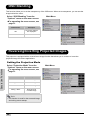
Setting a Background Image
This function allows you to select the image displayed when a signal is not being sent to the projector.
Selecting a Background
Image
Main Menu
Selected item
Description
Blue
Blue screen
Black
Black screen
Easy to Use Functions
Select “Background” from the
“Options” menu on the menu screen.
For operating the menu screen, see
page 31.
47
OSD Blending
This function allows you to set the transparency of the OSD menu. When set to transparent, you can see the
image behind the menu.
Select “OSD Blending” from the
“Options” menu on the menu screen.
For operating the menu screen, see
page 31.
Selected item
Description
ON
On-screen displays
are displayed.
OFF
Black screen
Main Menu
Reversing/Inverting Projected Images
This projector is equipped with a reverse/invert image function that allows you to reverse or invert the
projected image for various applications.
Easy to Use Functions
Setting the Projection Mode
Select “Projection Mode” from the
“Options” menu on the menu screen.
For operating the menu screen, see
page 31.
Selected item
Description
Front
Normal image
Ceiling + Front
Inverted image
Rear
Reversed image
Ceiling + Rear
Reversed and
inverted image
Note
• This function is used for the reversed image
and ceiling-mount setups.
48
Main Menu
Deinterlace
This function allows you to determine the type of incoming video content-film, static interlaced video and
moving interlaced video. Different algorithms are applied for each of the content types.
Select “Deinterlace” from the
“Options” menu on the menu screen.
For operating the menu screen, see
page 31.
Description
DCTI
This function is useful to
enhance video by replacing
the edges of the video with
edges that have steeper rise
and fall times. DCTI turns
sloped or sinusoidal
waveforms into rectangular
or square waveforms with
the same duty cycles and
peak-to-peak amplitude. It's
useful for 4:1:1 video
sources. The range is from
0 to 7.
Video on film
(VOF)
This function is used to
identify video artifacts while
in film mode. VOF attempts
to repair the artifacts using
the low-angle interpolator
while remaining in film
mode.
Film Mode
Reproduces the image of
the film source clearly.
Displays the optimized
image of film transformed
with 3:2 pull down (NTSC
and PAL60Hz)or 2:2 pull
down (PAL 50Hz and
SECAM) enhancement to
progressive mode images.
Easy to Use Functions
Selected item
Main Menu
Note
• In PAL50Hz or SECAM, the 2:2 pull down
enhancement will be enabled only in film
mode, after the film source has been
entered.
49
Reset
Select this option to set all items in the “Option”
menu to the factory default values.
Main Menu
Lamp Timer Reset
Lamp Timer Reset is used to reset the lamp
counter.
Easy to Use Functions
You should reset the Timer after you install a
new lamp. The cumulative lamp usage time is
shown in the Status Screen.
50
Main Menu
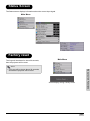
Status Screen
The Status screen displays information about the current input signal.
Main Menu
Factory reset
The Logo will be shown for about 20 seconds,
then the projector will be reset.
Main Menu
Note
Easy to Use Functions
• The Logo will be shown about 20 seconds,
and then the projector will be reset.
Screen display during Factory Reset
51
Easy to Use Functions
NOTES
52
Appendix
Appendix
53
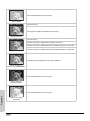
Maintenance
Cleaning the projector
Unplug the power cord before cleaning the projector.
Avoid using benzene or thinner, as these can damage the finish on the cabinet and operation panel.
Do not use volatile agents such as insecticides on the projector.
Do not leave rubber or plastic objects in contact with the projector for long periods as they may damage
the finish of the projector.
Wipe off dirt gently with a soft flannel cloth.
For hard-to-remove dirt, soak a cloth in a neutral detergent diluted with water, wring the cloth well and then
wipe the projector.
Strong cleaning detergents may discolor, warp or damage the coating on the projector. Make sure to test
on a small, inconspicuous area on the projector before using.
nt
rge
ete
al d
utr
Ne
Neutral detergent
diluted with water
Cleaning the lens
Use a commercially available blower or lens cleaning paper (for glasses and camera lenses) for cleaning
the lens. Do not use any liquid cleaning agents, as they may wear off the coating film on the surface of the
lens.
Cleaning
Paper
The surface of the lens is easily damaged, do not to scrape or hit the lens.
Appendix
Cleaning the exhaust and intake vents
Use a vacuum cleaner to clean dust from the exhaust vent and the intake vent.
54
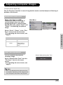
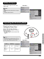
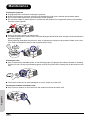
Cleaning the Ventilative Holes
• This projector is equipped with ventilative
holes to ensure the optimal operating
condition of the projector.
• Periodically clean the ventilative hole by
vacuuming it off with a vacuum cleaner.
• The ventilative holes should be cleaned
every 100 hours of use. Clean the
ventilative holes more often when the
projector is used in a dirty or smoky
location.
Side and Rear view
Ventilative holes
Ventilative holes
Cleaning the
Ventilative Holes
1
Turn off the power and
disconnect the power cord.
Bottom view
ENTER
STATUS
MENU
EXIT
ECO
INPUT
COMPONENT 1
COMPONENT 2
Press
on the projector or
on
the remote control to turn off the power.
Wait until the cooling fan stops.
2
Power button
Unplug the Power Cord.
Pr/Cr
Pb/Cb
Y
PC
DVI
Made in Taiwan
mp chassis cover while replacing the lamp.
xt to them until they have sufficiently cooled down.
nvironment.
3
Clean the dust off by placing the
cleaner hose on the intake and
exhaust ventilative holes.
Appendix
55
About the Lamp
The projector lamp has a life of 2000 hours. Maintain proper ventilation to keep the lamp operating
throughout its lifetime. Do not subject the projector to unnecessary vibration to ensure that the
lamp does not break.
It is recommended that the lamp (sold separately) be replaced after approximately 2,000 cumulative hours
of use or when you notice a significant deterioration in the picture and color quality. The number of hours
the lamp has been used can be checked with “Lamp Timer” in the “Options” menu on the menu screen.
For lamp replacement, please consult your nearest Authorized Service Center or Dealer.
The actual lamp service life may be less than 2000 hours depending on the environment in which the
projector is used.
Caution Concerning the Lamp
This projector uses a pressurized mercury lamp. A loud sound may indicate lamp failure. Lamp failure is
caused by excessive shock, improper cooling, surface scratches or deterioration of the lamp due to usage.
The period of time up to failure largely varies depending on the individual lamp and/or the condition and
the frequency of use. It is important to note that failure can often result in the bulb cracking.
When the lamp replacement indicator and on-screen display icon are illuminated or are flashing, it is
recommended that the lamp be replaced with a new one immediately, even if the lamp appears to be
operating normally.
If the lamp breaks glass particles may spread inside the lamp cage or gas contained in the lamp may be
vented into the room from the exhaust vent. As the gas in this lamp contains mercury, ventilate the room
well if the lamp breaks and avoid all exposure to the released gas. In case of exposure to the gas, consult
with a doctor as soon as possible.
If the lamp breaks, there is also a possibility that glass particles may spread inside the projector.
If this happens, it is recommended you contact your nearest Authorized Dealer to remove the damaged
lamp and assure safe operation.
Replacing the Lamp
Appendix
CAUTION! Do not remove the lamp unit immediately after operation of the projector. The
lamp will be hot and touching it can lead to burn or injury. Wait at least one hour after the
power cord is disconnected to allow the surface of the lamp unit to fully cool before removing
the lamp unit.
56
Removing and Installing the Lamp Unit
Follow these instructions to replace the lamp.
• Be sure to remove the lamp unit by the handle. Be sure not to touch the glass surface of the lamp unit or
the inside of the projector.
• To avoid injuring yourself and damage to the lamp, be sure to carefully follow the steps below.
• Do not loosen other screws except for the lamp unit cover and lamp unit.
(Only the silver screws are loosened).
1. If the projector is running, press
on the projector or
turn off the power. Wait until the cooling fan stops.
on the remote control to
ENTER
STATUS
MENU
EXIT
ECO
INPUT
COMPONENT 1
COMPONENT 2
Warning!
Do not remove the lamp unit from the projector right after use. The lamp will be very hot and may cause burn
or injury.
2. Disconnect the power cord and wait at least an hour for the lamp to cool.
3. Remove the lamp unit cover.
• Loosen the user service screw that secures the lamp unit cover. Then open the cover in the direction of the
arrow.
Appendix
M4* 8.9 screws
57
4. Remove the lamp unit.
• Loosen the securing screws from the lamp unit. Hold the lamp unit by the handle and pull it in the direction
of the arrow.
5. Insert the new lamp unit.
• Press the lamp unit firmly into the lamp unit compartment. Fasten the securing screws.
• Attach the lamp unit cover.
• Close the lamp unit cover in the direction of the arrow (to the close mark) on the side of the projector. Then
tighten the user service screw.
Info
• If the lamp unit and lamp cover are not correctly installed, the power will not turn on, even if the power cord
is connected to the projector.
Resetting the Lamp Timer
Reset the lamp timer after replacing the lamp.
Pr/Cr
1. Connect the power cord.
• Plug the power cord into the AC socket of the
projector.
Pb/Cb
Y
PC
DVI
Made in Taiwan
mp chassis cover while replacing the lamp.
xt to them until they have sufficiently cooled down.
nvironment.
2. Reset the lamp timer.
• While holding down
,
and
on the projector,
ENTER
press
on the projector. (See page 50)
• “LAMP 0H” is displayed, indicating that the lamp timer
is reset.
ENTER
Appendix
Info
Make sure to reset the lamp timer only when replacing
the lamp. If you reset the lamp timer and continue to
use the same lamp, this may cause the lamp to become
damaged or explode.
58
ENTER
STATUS
MENU
EXIT
ECO
INPUT
Connecting Pin Assignments
DVI-D port: 25 pin connector
• DVI Digital INPUT
24 23
~
18 17
8 7
~
~
21
Pin No.Signal
Pin No.Signal
1 T.M.D.S data 216 Hot plug detection
2 T.M.D.S data 2+
17 T.M.D.S data 0–
3 T.M.D.S data 2 shield 18 T.M.D.S data 0+
4 Not connected
19 T.M.D.S data 0 shield
5 Not connected
20 Not connected
6 DDC clock
21 Not connected
7 DDC data
22 T.M.D.S clock shield
8 Not connected
23 T.M.D.S clock+
9 T.M.D.S data 1–
24 T.M.D.S clock–
10 T.M.D.S data 1+
C1 Ground
11 T.M.D.S data 1 shield
12 Not connected
13 Not connected
14 +5V power from
graphic card.
15 Ground
C1
16
9
RS-232C Port: 9-pin D-sub Female connector of the DIN-D-sub RS-232C cable
54321
9876
Pin No.
1
2
3
4
5
6
7
8
9
Signal
Name
SD
RD
Send Data
Receive Data
SG
Signal Ground
I/O
Output
Input
Reference
Not connected
Connected to internal circuit
Connected to internal circuit
Not connected
Connected to internal circuit
Not connected
Not connected
Not connected
Not connected
Appendix
59
Computer Compatibility Chart
Computer
• Multiple signal support
Horizontal Frequency: 25–75 kHz, Vertical Frequency: 50–85 Hz, Pixel Clock: 25–108 MHz
• Compatible with sync on green and composite sync signals
• XGA compatible with advanced intelligent compression
The following is a list of modes that conform to VESA. However, this projector supports
other signals that are not VESA standards.
PC/
MAC/
WS
Resolution
640 x 350
720 x 350
640 x 400
PC
VGA
720 x 400
640 x 480
Horizontal
Vertical
DVI
VESA SupFrequency Frequency Standard
(kHz)
(kHz)
port
Display
PC/
MAC/
WS
Resolution
Horizontal
Vertical
DVI
VESA SupFrequency Frequency Standard
(kHz)
(kHz)
port
27.0
60
31.4
50
31.5
70
35.1
56
3
3
37.9
85
37.9
60
3
3
27.0
60
44.5
70
31.5
70
48.1
72
3
3
27.0
60
3
46.9
75
3
3
31.5
70
3
53.7
85
3
3
37.9
85
3
56.8
90
3
27.0
60
3
64.0
100
3
31.5
70
3
35.5
43
3
37.9
85
3
40.3
50
26.2
50
3
48.4
60
3
3
31.5
60
3
56.5
70
3
3
36.8
70
3
60.0
75
3
3
37.9
72
3
3
68.7
85
3
3
37.5
75
3
3
73.5
90
3
43.3
85
3
3
77.2
96
3
47.9
90
3
80.6
100
3
53.0
100
3
640 x 480
34.9
67
MAC SVGA
16”
832 x 624
49.6
75
MAC
19”
1024 x 768
48.4
60
3
SVGA
3
3
Upscale
800 x 600
PC
XGA
MAC
13”
VGA
XGA
1024 x 768
Display
3
3
Upscale
3
True
Upscale
3
True
Note
Appendix
• This projector may not be able to display images from notebook computers in simultaneous (CRT/LCD)
mode. Should this occur, turn off the LCD display on the notebook computer and output the display data
in “CRT only” mode. Details on how to change display modes can be found in your notebook computer’s
operation manual.
• When this projector receives 640 × 350 VESA format VGA signals, “640 × 400” appears on the screen.
• When projecting video images of an interlace video signal with the projector, the intended image may
not be projected depending on the video signal when using the RBG input. In such cases, use the
component input, S-video input or video input.
60
Video Compatibility Chart
Resolution
SD Video
H-Freq
(kHz)
V-Freq
(Hz)
Comp1
Support
Comp2
Support
S-Video ComposVGA
Support ite Support Support
NTSC
640x480i
15.73
59.94/60
3
3
3
3
PAL
768x576i
15.63
50
3
3
3
3
SECAM
768x576i
15.63
50
3
3
3
3
NTSC-4.43
U
U
U
U
PAL-M
U
U
U
U
PAL-N
U
U
U
U
NTSC-J
U
U
U
U
PAL-60
U
U
U
U
DVI
Support
NTSC-50
ED TV
HD TV
HTPC
480P
720x480P
31.5
59.94/60
3
3
3
3
576P
720x576P
31.3
50
3
3
3
3
1080i/50
1920x1080i
33.8
50
3
3
3
3
1080i/60
1920x1080i
28.1
59.94/60
3
3
3
3
720P/50
1280x720P
37.5
50
3
3
3
3
720P/60
1280x720P
45.0
59.94/60
3
3
3
3
720P/48
1280x720P
48
720P/75
1280x720P
75
1. Component 1/2 support signal formats are Y/Pb/Pr, Y/Cb/Cr
2. VGA port support signal formats are RGsyncB, RGBHV or RGBCsysc
3. “U” means manual setting is needed
DTV
Signal
Horizontal Frequency (kHz)
Vertical Frequency (Hz)
480I
15.8
60
DVI Support
480P
31.5
60
576I
15.6
50
576P
31.3
50
3
720P
45.0
60
3
720P
37.5
50
3
1080I
33.8
60
3
1080I
28.1
50
3
3
Troubleshooting
Problem
Check
Projector power cord is not plugged into the wall outlet.
Remote control batteries have run out.
Projector does not start
Appendix
The selected input mode is wrong.
Cables may be incorrectly connected to the rear panel of the projector.
Power to the external connected device is off.
The video signal format of the video equipment is not set correctly.
No picture
61
Picture adjustments are incorrectly set.
Color is faded
Adjust the focus
The projection distance exceeds the focus range.
Picture is blurred
(PC input only)
Perform "Fine Sync" adjustments ("Execute Auto tune")
Perform "Fine Sync" adjustments ("Clock" adjustment) also in component
Picture noise appears.
Perform "Fine Sync" adjustments ("Phase adjustment) also in component
Change the input signal type of the video equipment.
Picture is green on
INPUT1 or 2 COMPONENT
Picture adjustments are incorrectly set.
Picture is dark or
bright and whitish
Appendix
Picture adjustments are incorrectly set.
Picture is too bright
and whitish
62
Product Specifications
Item
Model No.
DLP Panel
Display Type
Resolution
Lens
Projection Lamp
Input Sources
Computer Compatibility
2D Lens Shift Ability
Brightness
Digital Keystone Correction
Projection Lens
Contrast Ratio
Uniformity
Screen Size
Throw Ratio (16:9)
Aspect Ratio
Projection Distance in 100”
Video Enhance
Projection Method
OSD Control
Video system
Matterhorn DLP Front Projector
Panel size: 0.63'' W-PAL
Display method: DMD by Texas Instruments
Device method: Digital Light Processing (DLPTM)
DLP Chip, RGB optical shutter method
1024 x 576 pixels
1-1.25 x zoom lens, F2.4~2.5, f= 19.1~23.9 mm
250 W / 200 W switchable UHP lamp
Video
VGA
YCbCr, YPbPr
CVBS (Composite Video)
S-Video
DVI-D
Control
RS-232 (For computer)
IR Receiver (For remote)
VGA,SVGA, XGA
Up/Down: ± 100%
Left/Right: ± 15%
800 ANSI Lumen - Bright Mode
± 15° Vertical / Horizontal correction (Estimated)
Zoom lens with manual focus and manual zoom adjust
2500:1
90%
30 ~ 300 inches
1.34:1 ~ 1.68:1
16:9 Native
3 m ~ 3.72 m
4-Line Y/C separation(2D)
DLTi, DCTi
Front / Rear, Desktop / Ceiling
Projector keypad
IR remote control
NTSC 3.58 / NTSC 4.43 / PAL / PAL-M / PAL-N / PAL 60 / SECAM /
EDTV480P /EDTV576P/HDTV720P /HDTV1080I
342 mm x 307 mm x 144 mm (13.5" x 12" x 5.6")(W x L x H)
14 lbs
100 ~ 240 V at 50 ~ 60 Hz
370 W (Standby mode < 5W)
5°C to 35°C
32 dba (ECO mode)
90 days or 500 hours
2 years parts
Appendix
Dimensions
Weight
Power Supply
Power Consumption
Operating Temperature
Audible Noise
Lamp Warranty
Product Warranty
Description
Specifications are subjected to change without notice.
63
Dimensions
Units: inches (mm)
Rear View
VIDEO
S-VIDEO
Pr/Cr
Pb/Cb
Pr/Cr
Y
Pb/Cb
PC
Y
DVI
RS-232
WARNING
Made in Taiwan
• Do not disassemble any components except the lamp chassis cover while replacing the lamp.
• Do not touch ventilation slots, lamp and objects next to them until they have sufficiently cooled down.
• Never insert any objects through ventilation holes.
• Do not use this unit near water or in a rainy/moist environment.
Side View
Side View
MENU
12 16 inch
KEYSTONE
STANDBY
11 16 inch
283.4 mm
INPUT
1
Temp led
3
307.1 mm
Top View
ENTER
LENS SHIFT
LENS SHIFT
(H)
(V)
Zoom
Focus
3
7
Front View
13 16 inch
341.8 mm
5
1 8 inch
3
41.6 mm
1 16 inch
8 4 inch
208.9 mm
1
1
7 16 inch
179.0 mm
Appendix
10 inch
253.6 mm
29.9 mm
Bottom View
64
5 inch
127.4 mm
1
3
1 4 inch
44.2 mm
15
8 2 inch
4 16 inch
216.1 mm
125.7 mm
160.8 mm
5
6 16 inch
11
5 16 inch
144.8 mm
15
4 16 inch
125.7 mm
85.7 mm
3 8 inch
1
8 2 inch
216.1 mm
LIMITED WARRANTY
Boxlight ("Boxlight") warrants that each Studio Experience Premiere 30HD ("the Product") sold hereunder will conform to
and function in accordance with the written specifications of Boxlight. Said limited warranty shall apply only to the first
person or entity that purchases the Product for personal or business use and not for the purpose of distribution or resale.
Said warranty shall continue for a period of three (3) years from the date of such purchase. The standard limited warranty
excludes the lamps in projectors after 120 days or 500 hours (whichever comes first) and the accessories after one year.
Boxlight does not warrant that the Product will meet the specific requirements of the first person or entity that purchases the
Product for personal or business use. Boxlight's liability for the breach of the foregoing limited warranty is limited to the repair
or replacement of the Product or refund of the purchase price of the Product, at Boxlight's sole option. Replacement Product
may be re-furbished in "like-new" condition, at Boxlight's sole discretion. To exercise the Purchaser's rights under the
foregoing warranty, the Product must be returned at the Purchaser's sole cost and expense, to Boxlight or to any authorized
Boxlight service center provided, and the Product must be accompanied by a written letter explaining the problem and which
includes (i) proof of date of purchase; (ii) the dealer's name; and (iii) the model and serial number of the Product. When
sending your unit in for repair, please ship your unit in its original packing material or a Boxlight approved ATA Shipping
Case, or have a professional packaging company pack the unit. Please insure your shipment for its full value. A return
authorization number, issued by the Boxlight Customer Service department, must also be clearly displayed on the
outside of the shipping carton containing the Product.
WARRANTY LIMITATION AND EXCLUSION
Boxlight shall have no further obligation under the foregoing limited warranty if the Product has been damaged due to
abuse, misuse, neglect, accident, unusual physical or electrical stress (unusual physical and electrical stress includes
unusually long operation, exposure to smoke and other airborne contaminants), unauthorized modifications, tampering,
alterations, or service other than by Boxlight or its authorized agents, causes other than from ordinary use or failure to
properly use the Product in the application for which said Product is intended.
DISCLAIMER OF UNSTATED WARRANTIES
THE WARRANTY PRINTED ABOVE IS THE ONLY WARRANTY APPLICABLE TO THIS PURCHASE. ALL OTHER
WARRANTIES, EXPRESS OR IMPLIED, INCLUDING, BUT NOT LIMITED TO, THE IMPLIED WARRANTIES OF MERCHANTABILITY AND FITNESS FOR A PARTICULAR PURPOSE ARE DISCLAIMED. THERE ARE NO WARRANTIES
THAT EXTEND BEYOND THE FACE HEREOF AND THE FOREGOING WARRANTY SHALL NOT BE EXTENDED,
ALTERED OR VARIED EXCEPT BY WRITTEN INSTRUMENT SIGNED BY BOXLIGHT. SOME STATES DO NOT ALLOW
LIMITATIONS ON HOW LONG AN IMPLIED WARRANTY MAY LAST, SO SUCH LIMITATIONS MAY NOT APPLY TO YOU.
LIMITATION OF LIABILITY
IT IS UNDERSTOOD AND AGREED THAT BOXLIGHT'S LIABILITY WHETHER IN CONTRACT, IN TORT, UNDER ANY
WARRANTY, IN NEGLIGENCE OR OTHERWISE SHALL NOT EXCEED THE RETURN OF THE AMOUNT OF THE
PURCHASE PRICE PAID BY PURCHASER AND UNDER NO CIRCUMSTANCES SHALL BOXLIGHT BE LIABLE FOR
SPECIAL, INDIRECT, INCIDENTAL OR CONSEQUENTIAL DAMAGES OR LOST PROFITS, LOST REVENUES OR LOST
SAVINGS. THE PRICE STATED FOR THE PRODUCT IS A CONSIDERATION IN LIMITING BOXLIGHT'S LIABIL-ITY. NO
ACTION, REGARDLESS OF FORM, ARISING OUT OF THE AGREEMENT TO PURCHASE THE PRODUCT MAY BE
BROUGHT BY PURCHASER MORE THAN ONE YEAR AFTER THE CAUSE OF ACTION HAS ACCRUED. SOME
STATES DO NOT ALLOW THE EXCLUSION OR LIMITATION OF INCIDENTAL OR CONSEQUENTIAL DAM-AGES SO
THE ABOVE LIMITATION OR EXCLUSION MAY NOT APPLY TO YOU. THIS LIMITED WARRANTY GIVES YOU
SPECIFIC LEGAL RIGHTS, AND YOU MAY ALSO HAVE OTHER RIGHTS WHICH VARY FROM STATE TO STATE.
Boxlight Corporation
19332 Powder Hill Place
Poulsbo, WA 98370-7407 USA
www.boxlight.com
USA and Canada 800-762-5757
International +1.360.779.7901
www.boxlight.com
www.studioexperience.com