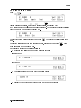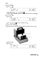
1
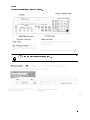
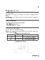
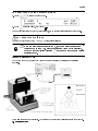
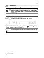
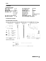
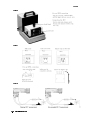
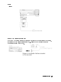
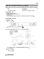
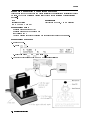
Agilent 4339B High Resistance Meter
User's Guide
Agilent Part No. 04339-90041
Printed in JAPAN January 2001
Fifth Edition
Notice
The information contained in this document is subject to change without notice.
This document contains proprietary information that is protected by copyright. All rights are
reserved. No part of this document may be photocopied, reproduced, or translated to another
language without the prior written consent of the Agilent Technologies.
Agilent Technologies Japan, Ltd.
Component Test PGU-Kobe
1-3-2, Murotani, Nishi-ku, Kobe-shi,
Hyogo, 651-2241 Japan
c Copyright 1996, 1999, 2000, 2001 Agilent Technologies Japan, Ltd.
4339B
Manual Printing History
March 1996 : : : : : : : : : : : : : : : : : : : : : : : : : : : : : : : : : : : : : : : : : : : First Edition (part number:
December 1996 : : : : : : : : : : : : : : : : : : : : : : : : : : : : : : : : : : : : Second Edition (part number:
July 1999 : : : : : : : : : : : : : : : : : : : : : : : : : : : : : : : : : : : : : : : : : : : : Third Edition (part number:
March 2000 : : : : : : : : : : : : : : : : : : : : : : : : : : : : : : : : : : : : : : : : Fourth Edition (part number:
January 2001 : : : : : : : : : : : : : : : : : : : : : : : : : : : : : : : : : : : : : : : : Fifth Edition (part number:
04339-90021)
04339-90031)
04339-90041)
04339-90041)
04339-90041)
iii
4339B
Safety Summary
The following general safety precautions must be observed during all phases of operation,
service, and repair of this instrument. Failure to comply with these precautions or with specic
WARNINGS elsewhere in this manual may impair the protection provided by the equipment.
In addition it violates safety standards of design, manufacture, and intended use of the
instrument.
The Agilent Technologies assumes no liability for the customer's failure to comply with these
requirements.
Note
4339B is designed for use in INSTALLATION CATEGORY II according to IEC
61010-1 and POLLUTION DEGREE 1 according to IEC 61010-1 and IEC 60664-1.
4339B is an INDOOR USE product.
Note
LEDs in 4339B are Class 1 in accordance with IEC60825-1.
CLASS 1 LED PRODUCT
Ground The Instrument
To avoid electric shock hazard, the instrument chassis and cabinet must be connected to a
safety earth ground by the supplied power cable with earth blade.
DO NOT Operate In An Explosive Atmosphere
Do not operate the instrument in the presence of ammable gasses or fumes. Operation of any
electrical instrument in such an environment constitutes a denite safety hazard.
Keep Away From Live Circuits
Operating personnel must not remove instrument covers. Component replacement and internal
adjustments must be made by qualied maintenance personnel. Do not replace components
with the power cable connected. Under certain conditions, dangerous voltages may exist even
with the power cable removed. To avoid injuries, always disconnect power and discharge
circuits before touching them.
DO NOT Service Or Adjust Alone
Do not attempt internal service or adjustment unless another person, capable of rendering rst
aid and resuscitation, is present.
DO NOT Substitute Parts Or Modify Instrument
Because of the danger of introducing additional hazards, do not install substitute parts or
perform unauthorized modications to the instrument. Return the instrument to a Agilent
Technologies Sales and Service Oce for service and repair to ensure that safety features are
maintained.
iv
4339B
Dangerous Procedure Warnings
Warnings , such as the example below, precede potentially dangerous procedures throughout
this manual. Instructions contained in the warnings must be followed.
Warning
Dangerous voltages, capable of causing death, are present in this
instrument. Use extreme caution when handling, testing, and adjusting
this instrument.
v
4339B
Certication
Agilent Technologies certies that this product met its published specications at the time
of shipment from the factory. Agilent Technologies further certies that its calibration
measurements are traceable to the United States National Institute of Standards and
Technology, to the extent allowed by the Institution's calibration facility, or to the calibration
facilities of other International Standards Organization members.
Warranty
This Agilent Technologies instrument product is warranted against defects in material and
workmanship for a period of one year from the date of shipment, except that in the case of
certain components listed in General Information of this manual, the warranty shall be for the
specied period. During the warranty period, Agilent Technologies will, at its option, either
repair or replace products that prove to be defective.
For warranty service or repair, this product must be returned to a service facility designated by
Agilent Technologies. Buyer shall prepay shipping charges to Agilent Technologies and Agilent
Technologies shall pay shipping charges to return the product to Buyer. However, Buyer shall
pay all shipping charges, duties, and taxes for products returned to Agilent Technologies from
another country.
Agilent Technologies warrants that its software and rmware designated by Agilent
Technologies for use with an instrument will execute its programming instruction when
property installed on that instrument. Agilent Technologies does not warrant that the operation
of the instrument, or software, or rmware will be uninterrupted or error free.
Limitation Of Warranty
The foregoing warranty shall not apply to defects resulting from improper or inadequate
maintenance by Buyer, Buyer-supplied software or interfacing, unauthorized modication or
misuse, operation outside the environmental specications for the product, or improper site
preparation or maintenance.
No other warranty is expressed or implied. Agilent Technologies specically disclaims the
implied warranties of merchantability and tness for a particular purpose.
vi
4339B
Exclusive Remedies
The remedies provided herein are buyer's sole and exclusive remedies. Agilent Technologies
shall not be liable for any direct, indirect, special, incidental, or consequential damages,
whether based on contract, tort, or any other legal theory.
Assistance
Product maintenance agreements and other customer assistance agreements are available for
Agilent Technologies products.
For any assistance, contact your nearest Agilent Technologies Sales and Service Oce.
Addresses are provided at the back of this manual.
vii
4339B
Safety Symbols
General denitions of safety symbols used on equipment or in manuals are listed below.
Instruction manual symbol: the product is marked with this symbol when it is
necessary for the user to refer to the instruction manual.
Alternating current.
Direct current.
On (Supply).
O (Supply).
This Warning sign denotes a hazard. It calls attention to a procedure, practice,
condition or the like, which, if not correctly performed or adhered to, could
result in injury or death to personnel.
This Caution sign denotes a hazard. It calls attention to a procedure, practice,
condition or the like, which, if not correctly performed or adhered to, could
result in damage to or destruction of part or all of the product.
Note denotes important information. It calls attention to a procedure,
practice, condition or the like, which is essential to highlight.
Axed to product containing static sensitive devices use anti-static handling
procedures to prevent electrostatic discharge damage to component.
Caution, risk of electric shock : Terminals which may be supplied from the
interior of the equipment at a voltage exceeding 1 kV, or allow connection to a
voltage exceeding 1 kV are marked with this symbol.
viii
4339B
4339B High Resistance Meter at a Glance.
Warning
Do not touch the UNKNOWN terminals or the electrodes of the accessory,
when the High Voltage indicator is ON.
ix
4339B
In User's Guide
Chapter 1, Preparation for Use
For initial turn on of the 4339B
Chapter 2, Operating the 4339B
Basic measurement operation
Getting acquainted with the 4339B|for beginners
Handy reference for common measurement tasks|for all users
Chapter 3, Measurement Examples
Measurement Examples for typical 4339B applications
Measuring Insulation Resistance of a Capacitor
Measuring Volume Resistivity of a Insulation Material
In the User's Guide, information on the following subjects is not discussed:
Initial Inspection
GPIB remote control
Using with Handler
Maintenance
Specications
Error Messages
For detailed information on these subjects, see the 4339B Operation Manual.
x
Contents
1. Preparation for Use
In This Chapter . . . . . . .
Power Requirements . . . . .
To Set Power LINE Voltage . .
To Set Power LINE Frequency
.
.
.
.
.
.
.
.
.
.
.
.
.
.
.
.
.
.
.
.
.
.
.
.
.
.
.
.
.
.
.
.
.
.
.
.
.
.
.
.
.
.
.
.
.
.
.
.
.
.
.
.
.
.
.
.
.
.
.
.
.
.
.
.
.
.
.
.
.
.
.
.
.
.
.
.
.
.
.
.
.
.
.
.
.
.
.
.
.
.
.
.
.
.
.
.
2. Operating the 4339B
In This Chapter . . . . . . . . . . . . . . . . . . . . . . . . . . . . . . .
To Reset 4339B to its Default Settings . . . . . . . . . . . . . . . . . . . . .
To Connect Test Fixture . . . . . . . . . . . . . . . . . . . . . . . . .
16008B Resistivity Cell . . . . . . . . . . . . . . . . . . . . . . . . . . .
16117B Low Noise Test Lead . . . . . . . . . . . . . . . . . . . . . . . .
16339A Component Test Fixture . . . . . . . . . . . . . . . . . . . . . .
To Perform Calibration|Canceling internal measurement errors . . . . . . . .
To Set Test Voltage . . . . . . . . . . . . . . . . . . . . . . . . . . . . . .
To Set Current Limit . . . . . . . . . . . . . . . . . . . . . . . . . . . . .
To Perform OPEN Correction
|Canceling the stray admittance in parallel with the DUT . . . . . . . . .
If \Out Of Limit" is displayed . . . . . . . . . . . . . . . . . . . . . . . .
To Connect DUT . . . . . . . . . . . . . . . . . . . . . . . . . . . .
To Select Measurement Parameter . . . . . . . . . . . . . . . . . . . . . .
Setting the Parameters for Resistivity Measurement . . . . . . . . . . . . .
Setting Thickness of the DUT . . . . . . . . . . . . . . . . . . . . . . .
Setting the Electrode Size . . . . . . . . . . . . . . . . . . . . . . . .
To Select Measurement Range . . . . . . . . . . . . . . . . . . . . . . . .
Auto Range mode|Automatically selecting the optimum measurement range .
Hold Range mode|Holding the measurement range of your choice . . . . . .
To Select Measurement Time Mode . . . . . . . . . . . . . . . . . . . . . .
To Set Averaging Rate|Stabilizing the measurement result . . . . . . . . . . .
To Select Trigger Mode . . . . . . . . . . . . . . . . . . . . . . . . . . . .
To Set Trigger Delay Time . . . . . . . . . . . . . . . . . . . . . . . . . .
To Use Deviation Measurement Function . . . . . . . . . . . . . . . . . . .
Setting the Deviation Reference Values . . . . . . . . . . . . . . . . . . .
Selecting the Deviation Mode . . . . . . . . . . . . . . . . . . . . . . . .
To Use Comparator Function . . . . . . . . . . . . . . . . . . . . . . . . .
Setting the Limit Values . . . . . . . . . . . . . . . . . . . . . . . . . .
Sorting . . . . . . . . . . . . . . . . . . . . . . . . . . . . . . . . . .
To Select Display Mode . . . . . . . . . . . . . . . . . . . . . . . . . . . .
To Select Beeper Mode . . . . . . . . . . . . . . . . . . . . . . . . . . . .
To Use Contact Check Function |Monitoring the connection of test electrodes and
DUT . . . . . . . . . . . . . . . . . . . . . . . . . . . . . . . . . . .
To Print Measurement Data . . . . . . . . . . . . . . . . . . . . . . . . . .
Setting the Printer . . . . . . . . . . . . . . . . . . . . . . . . . . . . .
1-1
1-1
1-1
1-2
2-1
2-2
2-2
2-2
2-3
2-3
2-4
2-4
2-4
2-5
2-5
2-6
2-6
2-7
2-7
2-7
2-8
2-8
2-8
2-8
2-9
2-9
2-9
2-10
2-10
2-10
2-11
2-11
2-11
2-12
2-13
2-13
2-14
2-14
Contents-1
Printing . . . . . . . . . . . . . . . . . . . .
Disabling Printing . . . . . . . . . . . . . . .
To Use Measurement Sequence Function
|Controlling charge-measurement in a sequence
Selecting the Measurement Sequence Mode . . .
Setting the Measurement Sequence . . . . . . .
Starting Measurement Sequence . . . . . .
Aborting Measurement Sequence . . . . . . . .
To Apply Test Voltage . . . . . . . . . . . .
To Trigger a Measurement . . . . . . . . . . . .
To Turn OFF Voltage Output . . . . . . . . .
Reference . . . . . . . . . . . . . . . . . . . .
Default Settings . . . . . . . . . . . . . . . .
Accessories Available . . . . . . . . . . . . . .
Test Fixtures and Test Leads . . . . . . . . .
16064B LED Display/Trigger Box . . . . . . .
Other Topics . . . . . . . . . . . . . . . . . . .
If You Have a Problem . . . . . . . . . . . . . .
3. Measurement Examples
In This Chapter . . . . . . . . . . . .
Measuring Insulation Resistance of Capacitor
Measurement Setup . . . . . . . . . . .
Measurement Procedure . . . . . . . . .
For More Information . . . . . . . . . .
Measuring Resistivity of Insulation Material .
Measurement Setup . . . . . . . . . . .
Measurement Procedure . . . . . . . . .
For More Information . . . . . . . . .
Contents-2
.
.
.
.
.
.
.
.
.
.
.
.
.
.
.
.
.
.
.
.
.
.
.
.
.
.
.
. . . . . . . . . . . . . .
. . . . . . . . . . . . . .
2-14
2-14
.
.
.
.
.
.
.
.
.
.
.
.
.
.
.
.
.
.
.
.
.
.
.
.
.
.
.
.
.
.
.
.
.
.
.
.
.
.
.
.
.
.
.
.
.
.
.
.
.
.
.
.
.
.
.
.
.
.
.
.
.
.
.
.
.
.
.
.
.
.
.
.
.
.
.
.
.
.
.
.
.
.
.
.
.
.
.
.
.
.
.
.
.
.
.
.
.
.
.
.
.
.
.
.
.
.
.
.
.
.
.
.
.
.
.
.
.
.
.
.
.
.
.
.
.
.
.
.
.
.
.
.
.
.
.
.
.
.
.
.
.
.
.
.
.
.
.
.
.
.
.
.
.
.
.
.
.
.
.
.
.
.
.
.
.
.
.
.
.
.
.
.
.
.
.
.
.
.
.
.
.
.
.
.
.
.
.
.
.
.
.
.
.
.
.
.
.
.
.
.
.
.
.
.
.
.
.
.
.
.
2-15
2-15
2-15
2-16
2-16
2-16
2-16
2-16
2-17
2-17
2-17
2-17
2-19
2-20
2-20
.
.
.
.
.
.
.
.
.
.
.
.
.
.
.
.
.
.
.
.
.
.
.
.
.
.
.
.
.
.
.
.
.
.
.
.
.
.
.
.
.
.
.
.
.
.
.
.
.
.
.
.
.
.
.
.
.
.
.
.
.
.
.
.
.
.
.
.
.
.
.
.
.
.
.
.
.
.
.
.
.
.
.
.
.
.
.
.
.
.
.
.
.
.
.
.
.
.
.
.
.
.
.
.
.
.
.
.
.
.
.
.
.
.
.
.
.
.
.
.
.
.
.
.
.
.
3-1
3-2
3-2
3-2
3-5
3-6
3-6
3-6
3-9
Figures
2-1. Printer Output . . . . . . . . . . . . . . . . . . . . . . . . . . . . . . .
2-14
Tables
1-1. Power Voltage Selector Setting . . . . . . . . . . . . . . . . . . . . . . .
1-1
Contents-3
1
Preparation for Use
In This Chapter
Before turning the 4339B ON, you must rst set the 4339B to match the available power LINE
voltage.
If the 4339B's power LINE voltage and frequency are properly set and ready to use, you can
skip this chapter.
Power Requirements
The 4339B's power source requirements are as follows:
LINE Voltage : 100 / 120 / 220 / 240 V ac (610%)
LINE Frequency : 47 to 66 Hz
Power Consumption : 45 VA maximum
To Set Power LINE Voltage
1. Conrm that the power cable is disconnected.
2. Slide the LINE Voltage selector on the rear panel to match the power LINE voltage which
will be used (see Table 1-1).
Table 1-1. Power Voltage Selector Setting
Voltage Selector
Line Voltage
100V/120Vac(610%)
220V/240Vac(610%)
Required Fuse
UL/CSA type, Time delay 0.5A 250V
(Agilent part number 2110-0202)
UL/CSA type, Time delay 0.25A 250V
(Agilent part number 2110-0201)
Preparation for Use
1-1
4339B
To Set Power LINE Frequency
1. Connect the power cable to the power cord receptacle on the rear panel.
2. Push the LINE switch in. The 4339B will emit a beep and perform the self test. (If any
message is displayed, see \Error Messages" back of 4339B Operation Manual.) The 4339B
will be ready for operation after a message like the following is displayed.
3. Press
. The following menu is displayed.
4. Press
until more blinks, and press
.
5. Press
until Line blinks, and press
.
A blinking item means that it is currently selected.
6. If the setting does not match the power LINE frequency, press
between 50Hz and 60Hz, then press
.
7. Select Exit and press
Note
1-2
to toggle the setting
to exit this menu.
The power line frequency setting is stored and is not changed after reset or
power-o. Once you set it, you do not need to set the line frequency again as
long as the same power line frequency is being used.
Preparation for Use
2
Operating the 4339B
In This Chapter
Basic measurement operations of the 4339B and references are explained.
Operating the 4339B
2-1
4339B
To Reset 4339B to its Default Settings
1. Press
2. Press
to select the reset menu.
until Yes blinks, and press
.
For more information about the default settings, see \Default Settings" later in this chapter.
To Connect Test Fixture
Connect the test xture to the UNKNOWN terminals as follows:
Do not touch the UNKNOWN terminals or the electrodes of the accessory,
Warning
when the High Voltage indicator is ON, the 4339B outputs dangerous
voltage of up to 1000 Vdc. Before handling the 4339B or the accessory,
turn OFF the test voltage pressing
and conrm that the High Voltage
indicator is OFF.
16008B Resistivity Cell
The 16008B is used to measure the volume or surface resistance/resistivity of insulation
materials.
Three size electrodes are available. For detail see \Accessories Available" later in this chapter.
2-2
Operating the 4339B
4339B
16117B Low Noise Test Lead
The 16117B is used to measure the resistance of insulation materials.
16339A Component Test Fixture
The 16339A is used to measure insulation resistance of electronic components.
Three type modules are available. For detail see \Accessories Available" later in this chapter.
* Measuring a high capacitance DUT keeping good S/N ratio, change the short bar to an
appropriate resistor. For detail, see page 3-6 of 16339A Component Test Fixture Operation and
Service Manual.
Operating the 4339B
2-3
4339B
To Perform Calibration|Canceling internal measurement errors
1. Press
.
2. Select ExecCal using
or
and press
. The 4339B will perform the calibration.
After the calibration is completed with the message Calibration Complete, the 4339B will
return to the measurement display.
To Set Test Voltage
1. Press
. The voltage setting menu will be displayed.
2. Enter the value using the numeric ENTRY keys (for example, to set 100 V, press
), then press
.
To Set Current Limit
1. Press
.
2. Enter the current limit value using the numeric keys, then press
to enter the value and
to exit.
Available current limits are:
0.5 mA (default)
5.0 mA (at test voltage 0 to 250 V only)
1.0 mA
10 mA (at test voltage 0 to 100 V only)
2.0 mA (at test voltage 0 to 500 V only)
2-4
Operating the 4339B
4339B
To Perform OPEN Correction
|Canceling the stray admittance in parallel with the DUT
1. Separate each electrode of the test xture. For details
about xture operation, refer to
\Test Fixtures and Test Leads" later in this chapter.
2. Press
. A source voltage is applied to the test
xture, and the V Output indicator will turn ON.
Warning
3. Press
Pressing
may cause the 4339B to output dangerous voltage, up to
1000 Vdc. Do not touch the UNKNOWN terminals or the electrodes of the
accessory when the V Output indicator is ON.
. The OPEN correction menu will be displayed.
4. Select OpenMeas using
or
and press
. The 4339B will perform the OPEN
correction.
After a while, the 4339B will display the message Correction Complete, and return to the
measurement mode.
5. Press
to turn the voltage OFF. The V Output indicator will turns OFF.
If \Out Of Limit" is displayed
The OPEN admittance is so high that it would be unsuitable for OPEN correction data.
Check that the test electrodes are properly opened.
Perform the OPEN correction again.
Operating the 4339B
2-5
4339B
To Connect DUT
Set the DUT to the test xture. For details, see \Test Fixtures and Test Leads".
Do not touch the UNKNOWN terminals or the electrodes of the accessory,
Warning
when the High Voltage indicator is ON, the 4339B outputs dangerous
voltage of up to 1000 Vdc. Before handling the 4339B or the accessory,
turn OFF the test voltage pressing
and conrm that the High Voltage
indicator is OFF.
To Select Measurement Parameter
1. Press
. The measurement parameter selection menu will be displayed.
2. Select the desired parameter using
or
and press
Rv:Volume resistivity v, Rs:Surface resistivity s)
Note
2-6
. (R:Resistance, I:Current,
If the 16008B resistivity cell is connected to the 4339B, to change volume and
surface resistivity, switch the volume/surface selector on the resistivity cell.
Operating the 4339B
4339B
Setting the Parameters for Resistivity Measurement
If you measure the volume or surface resistivity, set the parameters as follows:
Press
.
Setting Thickness of the DUT
1. Select Thickness using
or
and press
.
2. Enter the thickness value using the numeric ENTRY keys, and press
.
Setting the Electrode Size
1. Select ResCell using
or
and press
.
2. Select the electrode size that you want to use (26mm, 50mm, or 76mm) using
.
press
or
, and
3. Press
4. Select Exit and press
to exit the menu.
Operating the 4339B
2-7
4339B
To Select Measurement Range
Auto Range mode
|Automatically selecting the optimum measurement range
Press
. The Hold Range annunciator( 9 ) turns OFF.
Hold Range mode|Holding the measurement range of your choice
To select the measurement range,
1. Press
. The measurement range setup menu is displayed.
2. Press
or
until the desired range is displayed. Or, input the current value to
be measured using the numeric ENTRY keys, and the 4339B will select the optimum
measurement range setting.
3. Press
. The Hold Range annunciator( 9 ) turns ON.
Available measurement ranges:
100 pA (Not available at measurement time Short)
1 nA
10 nA
100 nA
1 A
10 A
100 A (Available at measurement time Short only)
To Select Measurement Time Mode
Press
until the Meas Time annunciator( 9 ) points to the desired measurement time mode :
Short, Med(Medium) or Long.
2-8
Operating the 4339B
4339B
To Set Averaging Rate|Stabilizing the measurement result
1. Press
.
2. Enter the averaging rate using the numeric ENTRY keys. (For example, to enter 4, press
.) You can enter integer values from 1 to 256. Also, you can increase or decrease the
value using
or
.
3. Press
to set the value and to exit.
To Select Trigger Mode
Press
until the Trigger annunciator( 9 ) points to the desired trigger mode.
Int(Internal)
Man(Manual)
Free running measurement
Triggers a measurement when
is pressed.
Ext(External) Triggers a measurement by external trigger signal input (through the external
trigger connector or handler interface).
To trigger a measurement in each mode, see \To Trigger a Measurement" later in this chapter.
To Set Trigger Delay Time
1. Press
.
2. Enter the desired trigger delay time using the numeric ENTRY keys. (For example, to set
0.5 s, press
.) You can set the trigger delay time from 0 s to 9.999 s.
3. Press
to set the value and to exit.
Operating the 4339B
2-9
4339B
To Use Deviation Measurement Function
Setting the Deviation Reference Values
1. Press
.
2. Select 1RefEnt using
or
and press
.
3. Enter the numeric value using the numeric ENTRY keys.
4. Press
to enter the value.
Selecting the Deviation Mode
5. Select ModeSet using
or
and press
6. Select the desired mode using
1ABS mode:
1% mode:
2-10
or
.
and press
Measured value0Reference
(Measured value0Reference)/Reference 2 100 %
Operating the 4339B
.
4339B
To Use Comparator Function
Setting the Limit Values
1. Press
2. Enter the lower limit value using the numeric ENTRY keys, then press
value. You can set the value from 09.90021037 to 9.90021037 .
3. Press
.
to enter the
4. Enter the upper limit value using the numeric ENTRY keys, then press
to enter the
37
37
value and to exit. You can set the value from 09.900210 to 9.900210 .
Sorting
To start sorting,
Press
. The Comprtr On annunciator( 9 ) turns ON.
To turn sorting OFF,
Press
again. The Comprtr On annunciator turns OFF.
The sorting results are HIGH, IN, and LOW.
Where,
HIGH
greater than higher limit
IN
between higher limit and lower limit
LOW
less than lower limit
The 4339B shows the comparison results using the display, beeper, printer, and
16064B LED Display/Trigger Box. (To use the 16064B, see \Accessories Available" later in this
chapter.)
For result output to the display, see \To Select Display Mode" in the next page.
For result output to the beeper, see \To Select Beeper Mode" in the next page.
For result output to the printer, see \To Print Measurement Data" later in this chapter.
Operating the 4339B
2-11
4339B
To Select Display Mode
.
Press
Select the desired mode using
or
and press
.
(Data:Measurement Display, Comprtr:Comparison Display, Off:Display OFF)
If you select Formt, the following menu will be displayed. You can select the display digits and
display format of the Measurement Display mode.
To select the display digits, select Digit and press
. Then select the display digits from 3,
4 or 5.
To selet the display format for the measurement data, select R-Unit and press
. Then
select Exponent mode or Prefix mode.
Each display mode shows the result as follows:
The Measurement Display mode shows the measurement data:
Exponent mode
Prefix mode
The Comparison Display mode shows the comparison results:
The Display OFF mode (DISP OFF) does not show any measurement result.
2-12
Operating the 4339B
4339B
To Select Beeper Mode
To change the beeper mode for the comparator result reporting:
1. Press
.
2. Select Beep using
or
and press
3. Select the beep mode using
or
to select.
, and press
to exit to the previous display.
No beep
Emits a beep when the comparator result is HIGH, LOW, or the contact
check FAILed.
PASS
Emits a beep when the comparator result is IN.
4. Select Exit using
or
, and press
to exit.
OFF
FAIL
To Use Contact Check Function |Monitoring the connection of
test electrodes and DUT
To enable or disable the contact check function:
1. Press
.
2. Select ON/OFF using
or
3. Select On or Off using
4. Select Exit using
and press
or
or
, and press
, and press
to select.
to exit to the previous display.
to exit.
5. The Cont Chk annunciator( 9 ) turns ON if the contact check function is on.
When contact check failed, the 4339B displays N.C.(No-Contact). The limit value for the
contact check function is changable. Refer to Operation Manual.
The OPEN correction function must be performed correctly for a valid contact check.
Operating the 4339B
2-13
4339B
To Print Measurement Data
Setting the Printer
1. Use an GPIB compatible printer, set to the listen-always mode.
2. Connect the printer to the 4339B's GPIB port on the rear panel.
3. Turn the printer ON.
Printing
Set the 4339B to talk only mode (Set the 4339B's GPIB address to 31).
1. Press
.
2. Press
. The Talk Only annunciator( 9 ) turns ON, and the printer begins printing the
measurement data.
Figure 2-1. Printer Output
Disabling Printing
Change the GPIB address to an address other than 31 (for example, 17, which is the default
setting).
Press
.
2-14
Operating the 4339B
4339B
To Use Measurement Sequence Function
|Controlling charge-measurement in a sequence
Selecting the Measurement Sequence Mode
Press
.
Select the desired mode using
or
and press
.
Single mode
Continuous mode
Measurement sequence OFF (normal measurement mode)
Setting the Measurement Sequence
1. Press
. The sequence mode menu will be displayed.
Single
Continuous
Off
2. Set Charge time.
a. Select Chrg using
or
and press
.
b. Enter the charge time using the numeric ENTRY keys, and press
.
3. Set Interval time and Number of repetitions (Cont mode only).
a. Select Intvl using
or
and press
.
b. Enter the interval time using the numeric ENTRY keys, and press
.
c. Enter the number of measurement points (equivalent to Memory size), and press
4. Select Exit and press
.
to exit.
Operating the 4339B
2-15
4339B
Starting Measurement Sequence
Press
. The Seq Running annunciator( 9 ) turns ON.
Warning
Pressing
may cause the 4339B to output dangerous voltage, up to
1000 Vdc. Do not touch the UNKNOWN terminals or the electrodes of the
accessory, when the V output indicator is ON.
Aborting Measurement Sequence
Press
. The Seq Running annunciator( 9 ) turns OFF.
Press
To Apply Test Voltage
. The V Output indicator turns ON.
Warning
Pressing
may output dangerous voltage, up to 1000 Vdc. Do not
touch the UNKNOWN terminals or the electrodes of the accessory when
the V Output indicator is ON.
To Trigger a Measurement
In internal trigger mode|The 4339B makes continuous free-running measurements.
In manual trigger mode|Press
when you want to trigger a measurement.
In external trigger mode| Connect the external trigger source to the EXT TRIGGER terminal
on the 4339B's rear panel, and apply a TTL level trigger signal to trigger a measurement.
(For details, see the 4339B Operation Manual.)
Note that the 4339B must be set to the external trigger mode to be triggered from an
external handler or from the 16064B LED Display/Trigger Box.
To Turn OFF Voltage Output
Press
and conrm the V Output indicator and the High Voltage indicator is turn OFF.
Warning
2-16
If the High Voltage Indicator turns ON after turning OFF the test voltage,
the DUT is still charged. This happens especially for capacitive DUTs. Do
NOT handle the DUT while the High Voltage Indicator is turned ON. When
the charge on the DUT discharges to a safe level(less than 42 V) the High
Voltage indicator will turn OFF.
Operating the 4339B
4339B
Reference
Default Settings
Test voltage output
: OFF
Test voltage
:0V
Current limit
: 0.5 mA
Measurement parameter : R
Resistivity cell
D1 : 50 mm
D2 : 70 mm
t : 2 mm
B :0
Deviation measurement : OFF
Measurement range
: Auto
Measurement time
: MEDium
Averaging rate
:1
Trigger mode
: Internal
Trigger delay time
: 0 ms
Comparator
: OFF
Contact check
: OFF
Display mode
: Measurement mode
Beep mode
: FAIL mode
Oset-error canceling : OFF
OPEN correction data is cleared
Accessories Available
Test Fixtures and Test Leads
Following test xtures and test leads are available for the 4339B for various forms of DUTs.
Operating the 4339B
2-17
4339B
16008B
16339A
16117B
2-18
Operating the 4339B
4339B
16118A
16064B LED Display/Trigger Box
The 16064B LED Display/Trigger Box triggers a measurement when its trigger key is pressed,
and displays the comparison results using LEDs. It allows you to manually operate the
comparator function of the 4339B.
Operating the 4339B
2-19
4339B
Other Topics
For details on these functions, see the 4339B Operation Manual.
Initial Inspection | Chapter 1 of the Operation Manual
Auto-Oset Canceling | Chapter 2 and Chapter 3 of the Operation Manual
Key Lock Function | Chapter 2 and Chapter 3 of the Operation Manual
GPIB | Chapter 4 and Chapter 5 of the Operation Manual
Handler Interface | Chapter 3 and Appendix B of the Operation Manual
Save / Recall | Chapter 2 and Chapter 3 of the Operation Manual
Backup Function | Chapter 3 of the Operation Manual
Specication | Chapter 8 of the Operation Manual
Maintenance | Chapter 9 of the Operation Manual
Error Messages | \Error Messages" in back of the Operation Manual
If You Have a Problem
If any of the problems listed below occur, follow the instructions given for the problem.
If you nd yourself lost when operating the 4339B
You can get back on track by:
To return to the measurement mode Press
several times. When Exit is in the menu,
select it and press
.
To return to the default settings
. Select Yes and press
.
Press
If the reset is not accepted, conrm that the Key
Lock annunciator( 9 ) is turned ON. See next.
If the 4339B does not accept key input:
Check whether or not the Key Lock annunciator( 9 ) is ON. If so:
Press
. The Key Lock annunciator( 9 ) turns OFF and the front-panel keys are
unlocked.
Check that the 16064B LED display/trigger box is connected to the 4339B and it is set to
lock out the keys. If so, unlock the keys from the 16064B.
If
is not accepted:
Check whether the interlock connector is rmly connected.
If you are using the 16008B or the 16339A,
Check whether the top cover of the test xture is closed.
If ------ or \OVLD" is displayed:
The measurement result is out of the measurable range. Check the DUT and make sure the
measurement range is properly set.
2-20
Operating the 4339B
3
Measurement Examples
In This Chapter
The 4339B's features are discussed, which you can investigate by trying the typical
measurement examples described in this chapter.
Do not touch the UNKNOWN terminals or the electrodes of the accessory,
Warning
when the High Voltage indicator is ON, the 4339B outputs dangerous
voltage of up to 1000 Vdc. Before handling the 4339B or the accessory,
turn OFF the test voltage pressing
and conrm that the High Voltage
indicator is OFF.
Measurement Examples
3-1
4339B
Measuring Insulation Resistance of Capacitor
This example shows the procedure to measure insulation resistance of capacitor after charged 1
minute. Using the test sequence measurement function reduces the measurement complexity.
Requirements
DUT
Test Fixture : 16339A, SMD module
Chip ceramic capacitor
Measurement Setup
Measurement Parameter : R
Measurement Range : Auto range mode
Test Voltage : 100 V
Use the measurement sequence single mode (measure after charged for 1 minute.)
Measurement Procedure
1. Reset the 4339B.
a. Press
.
b. Select Yes using
or
and press
.
2. Connect the test xture to the UNKNOWN terminals as follows:
* For detail, see \16339A Component Test Fixture" in Chapter 2.
3. Perform calibration.
.
Press
3-2
Measurement Examples
4339B
Select ExecCal using
or
and press
. After a while, the calibration will be
completed with the message \Calibration Complete".
4. Set the test voltage.
a. Press
.
b. Press
to set the test voltage to 100 V.
5. Perform the OPEN correction.
a. Separate the test electrodes and x them (nothing must be connected to the electrodes).
b. Close the cover.
c. Press
.
d. Select I using
or
and press
to select the current measurement mode.
displayed.
e. Press
. The Meas Time annunciator( 9 ) will indicate Long.
f. Press
to turn ON the test voltage.
The V Output indicator will turn ON.
g. Wait until the I value has stabilized within 0.5 pA.
Measurement Examples
3-3
4339B
.
h. Press
i. Select OpenMeas using
or
and press
.
After a while, the OPEN correction will be completed with the message \Correction
Complete". (If Out Of Limit is displayed, see \
To Perform OPEN Correction
|Canceling the stray admittance in parallel with the DUT" in Chapter 2.)
j. Press
to turn OFF the test voltage. The V Output indicator will turn OFF.
6. Connect the DUT and close the cover.
7. Press
.
8. Select R using
or
and press
to select the resistance measurement mode.
R(Resistance).
9. Set the measurement sequence charging time to 1 minute.
a. Press
.
b. Select Chrg using
c. Press
d. Select Exit and press
3-4
Measurement Examples
or
and press
.
to exit.
.
4339B
e. Press
.
f. Select Single using
or
and press
.
10. Press
. After charging 1 minute, the measuremen result will be displayed. The
following gure shows the typical measurement result display.
For More Information
To print out the measurement result | See \To Print Measurement Data" in Chapter 2
To select measurement level | See \To Set Test Voltage" in Chapter 2
Measurement Examples
3-5
4339B
Measuring Resistivity of Insulation Material
This example shows the procedure to measure resistivity of an insulation material after charged
1 minute. The 16008B Resistivity Cell is a right tool to measure resistivity of solid insulation
materials.
Requirements
DUT
Test Fixture : 16008B, 50 mm electrode
Insulation Material
(5 mm 2 120 mm 2 120 mm)
Measurement Setup
Measurement parameter : Rv(v)
Measurement Range : Auto range mode
Test Voltage : 500 V
Use the measurement sequence single mode (measure after charged for 1 minute.)
Measurement Procedure
1. Reset the 4339B.
a. Press
.
b. Select Yes using
or
and press
.
2. Connect the test xture to the UNKNOWN terminals as follows:
3-6
Measurement Examples
4339B
3. Perform calibration.
a. Press
.
b. Select ExecCal using
or
and press
.
After a while, the calibration is completed with the message \Calibration Complete".
4. Set the test voltage.
a. Press
.
b. Press
to set the test voltage to 500 V.
5. Perform the OPEN correction.
a. Turn the load knob counterclockwise(ccw) until the upper electrode does not move.
b. Close the cover.
c. Press
.
Measurement Examples
3-7
4339B
d. Select I using
or
and press
to select the current measurement mode.
e. Press
. The Meas Time annunciator( 9 ) will
indicates Long.
f. Press
. The V Output indicator will turn ON.
g. Wait until the I value has stabilized within 0.5 pA.
h. Press
.
i. Select OpenMeas using
or
and press
.
After a while, the OPEN correction is completed with the message \Correction
Complete". (If Out Of Limit is displayed, see \
To Perform OPEN Correction
|Canceling the stray admittance in parallel with the DUT" in Chapter 2.)
j. Press
. The V Output indicator will turn OFF.
6. Set the DUT.
a. Place the DUT on the Main electrode.
b. Turn the load knob and stick the electrode on the DUT.(Let the load scale indicate more
than 0 kg and less than 10 kg.)
c. Close the cover.
7. Set the measurement parameter to Rv(v : volume resistivity).
a. Turn the Volume/Surface selector of the 16008B to \Volume".
b. Press
.
c. Select Rv using
3-8
Measurement Examples
or
and press
.
4339B
8. Set the measurement sequence charging time to 1 minute.
a. Press
.
b. Select Chrg and press
c. Press
.
d. Select Exit and press
e. Press
.
to exit.
.
f. Select Single using
or
and press
.
. After charging 1 minute, the measurement result will be displayed. The
9. Press
following gure shows the typical measurement result display.
For More Information
To print out the measurement result | See \To Print Measurement Data" in Chapter 2
To select other measurement parameters | See \To Select Measurement Parameter" in
Chapter 2
To select measurement level | See \To Set Test Voltage" in Chapter 2
Measurement Examples
3-9