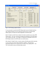
1
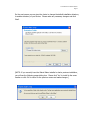
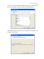
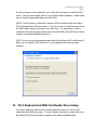
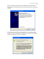
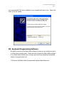
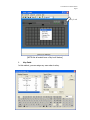
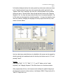
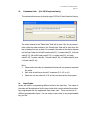
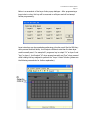
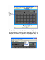
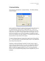
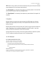
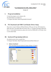
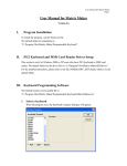
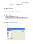
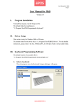
User Manual for Matrix Maker
Page 1
User Manual for Matrix Maker
TG3 Version 1.14
I.
System Requirements and Program Installation
System Requirements to use Matrix Maker software: Windows 2000 or Windows XP and
the appropriate ports to connect your keyboard (USB or PS/2). The keyboards will be
functional under other operating systems but can only be programmed in a Windows
2000 or Windows XP environment with the current release.
To install the Matrix Maker software, please run the latest “Matrix Maker Setup.exe” file
that is available for down load at http://www.tg3electronics.com/downloads.php .
The default installation directory is:
C:\Program Files\Matrix Maker\Programmable Keyboard
After running the “Matrix Maker Setup.exe” file , you will see the following screen.
Please click ‘Next” to proceed with the installation.
User Manual for Matrix Maker
Page 2
On the next screen you are given the choice to change the default installation directory
to another directory of your choice. Please make any necessary change s and click
‘Next’.
[NOTE: If you currently have the Matrix Maker installed or had a previous installation,
you will see the following popup dialog box. Please click ‘Yes’ to install to the same
location or click ‘No’ to return to the previous screen and make changes.]
User Manual for Matrix Maker
Page 3
If you wish to change the default Matrix Maker program group on the Start Menu, you
may do so at this screen or click ‘Next’ to proceed with the default options.
The installation program is now ready to copy the necessary file s and settings to your
computer. Please click ‘Next’.
User Manual for Matrix Maker
Page 4
On the final screen of the installation, you will be given the option to install the PS/2
driver*, view the user manual, and/or run the Matrix Maker application. Please make
sure to check the appropriate boxes and click ‘Finish’.
[NOTE: The PS/2 driver is required for Windows 2000 and Windows XP users with a
PS/2 keyboard and/or MSR card reader. If you do not wish to install this driver during
the Matrix Maker setup you may do so at a later time. For instructions on how to
install the driver at a later time, please refer to the file POSKB_DRV_SETUP.pdf which is
located in the default installation directory.]
[NOTE: If you are using an operating system other than Windows 2000 or Windows XP,
please do not install the PS/2 driver as it is not compatible with these operating
systems.]
II. PS/2 Keyboard and MSR Card Reader Driver Setup
This section applies to Windows 2000 and Windows XP® users who have a PS/2
keyboard and/or MSR card reader. For more detailed instructions, please refer to the
file POSKB_DRV_SETUP.pdf which is located in the default installation folder.
User Manual for Matrix Maker
Page 5
Below are screenshots from the PS/2 driver installation using the Matrix Maker
checkbox method. Please click next when you see this first screen to continue with
installation.
On the next screen you should see a file progress bar. If you receive a warning
message similar to the image shown below during this time, please click ‘Continue
Anyway’ to proceed with the PS/2 driver installation.
User Manual for Matrix Maker
Page 6
Your programmable PS/2 driver installation is now complete and ready to use. Please click
‘Finish’ to exit the installer.
III. Keyboard Programming Software
By default a shortcut to the Matrix Maker software is placed on your desktop as well as
in a Start Menu program group. Please use these to launch the Matrix Maker software.
If you delete these shortcut icons, you may open the file by navigating to the default
location of program which is at
“C:\Program Files\Matrix Maker\Programmable Keyboard\MatrixMaker.exe”
User Manual for Matrix Maker
Page 7
Select a keyboard
When the program runs, the following dialogue will appear.
Select the model, interface, and country layout of the keyboard you want to
program and then click the ‘OK’ button. The following instructions are base d on a
78-key model but can also be applied for other models.
1. Create a new Key Map
After selecting your product you will be displayed with the default key layout which
has no data for the reprogrammable keys. This can be treated as a new key map, or
you may click on File > New > Key Map.
2. Edit Key Map
You may notice that if you roll your mouse over certain keys on the key map they will
change to a light grey color. This indicates that the keys are programmable.
Clicking the left mouse button on that programmable key will display a popup menu
with options of assigning functions to that key. There are five methods to assign a
function to the programmable key which will be explained in greater detail in the
following sections. An example of the key map screen and the five programming
functions is shown below.
User Manual for Matrix Maker
Page 8
Key Lock
[NOTE: Not all models have a ‘Key Lock’ feature.]
i.
Key Code
In this method, you can assign any scan codes to a key.
User Manual for Matrix Maker
Page 9
In the above dialogue window, the most popular key codes (scan codes) are shown
in the “virtual keyboard” area, plus a few special codes which are listed in the
“Special Codes” area. Selecting a key from the “virtual keyboard” area or double
clicking an item in “Special Codes” area will add that key’s code to the “Mapping
Sequence” list. You may also type codes directly from a connected keyboard. Up
to 256 codes can be mapped to a single key position. You may also be able to see
more key codes by changing the language of the key layout from the ‘Key Code’
screen as shown below:
Any key codes (scan codes) that are not selectable in this screen can be mapped by
directly entering the hexadecimal code for that key into the box next to “0x” and
pressing “Insert”.
Example
If you press “Shift”, “H”, “E”, “Shift”, “L”, “L”, and “O” buttons in the “virtual
keyboard”, the “Mapping Sequence” list will be shown as in the above window.
After programming this key code sequence and sending the updated mapping to
the keyboard (covered in a later section), it will display “HEllo” if Caps Lock is off or
“heLLO” if Caps Lock is on.
User Manual for Matrix Maker
Page 10
If you want to delete “O” in the above “Mapping Sequence” list, you can right click
the “O” item. A popup menu with two options will appear. Selecting the “Delete”
option will delete the “O” item. Selecting the “Cle ar All” option will remove all the
items in the “Mapping Sequence” list.
If you wanted to add “S” before “H” in the above “Mapping Sequence” list, click the
“H” item in the list first, then click “S” in the “virtual keyboard” picture .
If you want to append key codes to the end of the list, please make sure to select
an empty mapping position in the “Mapping Sequence” list (for example, position 9
in the “Mapping Sequence” list on the previous screenshot).
Caution:
1. Please pay special attention when using the Shift, Alt, and Ctrl keys as they
have two states: down and up. For example, if you press the left Shift key
once in the “virtual keyboard” area, you will only get a down code which will
keep the key in a down state. If you were to keep this programming and press
that key in an application, it would behave as if the left Shift key was down
continuously. Again please pay special attention to the function of these keys
and their respective up/down codes to get the functions you desire.
2. For the PS/2 interface, if the “Pause” code is assigned, no other codes can be
appended to that key. It is also true that if any other codes are assigned the
“Pause” code may not be appended to that key.
3. For USB interface, the following codes cannot be assigned with oth er codes:
“Wake”, “Sleep”, “Power”, “Vol Up”, “Vol Down”, “Media Select”, “Mail”,
“Calculator”, “My Computer”, and “WWW Search ”. It is also true that if any
other codes are assigned, these codes may not be appended to that key.
ii.
ASCII Code
Using the ASCII method, you can assign any printable ASCII Codes, i.e. A-Z, a-z,
0-9, +, - ,* , / , and punctuation symbols. Up to 255 ASCII codes can be assigned.
Five special symbols can also be assigned by using the following representations:
User Manual for Matrix Maker
Page 11
Symbol
Representation
Enter Character
\n or \N
Esc Character
\e or \E
Tab Character
\t or \T
\ Character
Delay 0.5 second
\\
\d or \D
ASCII Code
\xHH where HH must be a
two-digit hexadecimal integer
For example, if you program a key with “Hello \nWorld ”, as shown in th e following
dia logue, the key will output:
Hello
World
Note:
1. Caps Lock will not modify the output of keys using this method. The key codes
will always be output in the same way they are programmed in.
2. The output of the character string follows the Country Code setting in the
Keyboard Setting dialogue (Refer to Section 3). For example, if you enter
“How are you?” from the keyboard connected to your PC with a German layout,
but you choose USA for the Country Code in the Keyboard Setting dialogue of
the keyboard you are programming, the output will become “How are zou?”.
User Manual for Matrix Maker
Page 12
iii.
Customize Code
(For PS/2 keyboard only)
This method allows a user to directly assign PS/2 Set 2 Scan Codes for the key.
The codes entered in the “Make Code” field will be sent if the key is pressed
down while the codes entered in the “Break Code” filed will be sent when the
key is released into an up state. For example, the codes in the above diagram
are the Scan Codes for left shift’s make code(12), h’s make code(33), h’s break
code(f0 33), left shift’s break code(f0 12), e’s make code(24), e’s break
code(f0 24), l’s make code(4b), l’s break code(f0 4b), o’s make code(44) and
o’s break code(f0 44).
Note:
1. Please enter the codes in hexadecimal format and use spaces to separate
iv.
2.
the codes.
Each code should have at most 2 characters (0-9, A-F or a-f).
3.
Please do not use codes 00 or 02 as they are reserved by the program.
Layer Index
Layers are useful in programming different codes to the same key. The output of
the codes will be determined by the layer index which can be selected by another
key programmed with the appropriate layer index code. There are at most 16
different programmable layers. You can assign a layer index to any programmable
key you like.
User Manual for Matrix Maker
Page 13
Below is a screenshot of the Layer Index popup dialogue. After programming a
layer index to a key, this key will be reserved on all layers and will not accept
further programming.
Layer index keys can be regarded as performing a function much like the Shift key:
when pressed a nd held down, it will output a different code than the base layer
would normally send. For example if I program a key to output “hi” on layer 0 and
“bye” on layer 1, it will output “hi” when pressed normally and “bye” when pressed
while holding the key assigned to perform the “Layer 1 index” function (please see
the following screenshots for further explanation).
User Manual for Matrix Maker
Page 14
To program key codes on alternate layers, please select each layer from the drop
down menu located on the toolbar (shown in the below screenshot) and program
key codes as explained in the previous sections. Please keep in mind that you
must assign a corresponding layer index key to output layer-based codes. You
may also assign layer indexes to the key lock feature if available (optional).
User Manual for Matrix Maker
Page 15
3. Keyboard Setting
On the menu bar, click Keyboard > Keyboard Settings. The following dialogue
window will appear:
If you would like the keyboard to perform the auto-repeat function built into your
PC’s operating system, please check the ‘Repeat Enable’ box. If this is not
selected the code associated with each key will only be output once even while
holding down a key. [NOTE: Choosing ‘Repeat Enable’ and assigning a non-layer
index key code setting for any of the key lock positions (if available) will cause
those key code settings to be output repeatedly. We recommend only setting the
key lock positions to layer indexes for this reason.]
To make the keyboard beep upon pressing a key, please check the ‘Beep Enable’
box. You may then select if you would like all keys to beep or only programmed
keys to beep when pressed down.
Depending on what model keyboard is selected, you may be able to assign a
country code in the keyboard setting. This country code will affect the MSR card
reader (if available) and the keys programmed using the ASCII code method.
[NOTE: To display the mapping correctly on your PC, you should choose the
Country Code in the Keyboard Setting dialogue window compatible with your OS
language.]
User Manual for Matrix Maker
Page 16
After editing the settings you may click the ‘Update’ button to send them directly to
the keyboard or you may click ‘OK’ to save the settings in the program memory
(settings will not be transferred to the keyboard until you click the ‘Update Key
Mapping’ button – see section 8 for more information).
4. Magstripe Card Reader Setting (Optional)
On the menu bar, click Keyboard > MagStripe Card Reader Settings (or click the
icon on the toolbar). T he following dialogue window will appear:
The header, separator, and suffix can be programmed by clicking the ASCII or Code
radio buttons. This will bring up a window for input similar to programming
normal keys on the keyboard.
Options
The following settings are not supported by all devices, please contact us for more
information if you find that your device does not support these settings.
1. Detect IBM card
Some IBM cards have special formats. If you want to read the card correctly,
you may try to select this option.
2.
Support OPOS
This option can be used on any system using our OPOS MSR drivers.
User Manual for Matrix Maker
Page 17
3.
Reverse reading
Track data will be read from right to left instead of left to right (default). It may
be suitable for some languages such as Hebrew.
4.
Output data for any valid track
If there is an invalid track in the card, this option will display the remaining
5.
valid tracks.
Output credit card A/C No.
6.
Displays the credit card A/C No. (track 2 only).
Enable LRC
7.
Displays the LRC after the end sentinel for each track.
Shown in digital format
If checked, the LRC will be displayed in the 2 -byte digital format. If it is
unchecked, the LRC will be displayed in the character format. For example, if
the LRC in Track 1 is 0x31, it will display “31” when it is checked and it will
display “Q” when it is unchecked.
Note:
1.
2.
The code length for header, separator, and suffix is limited to 16 characters.
For some PS/2 and USB devices, each sentinel length is limited to 16
characters. You can use \n to represent the new line character in each
sentinel.
According to the settings in the above dialogue window, after you slide a magstripe
card along the reader, it will output the following information in order:
Header codes, Track 1 Start Sentinel, Track 1 Data, Track 1 End Sentinel, Separator
codes, Track 2 Start Sentinel, Track 2 Data, Track 2 End Sentinel, Separator codes,
Track 3 Start Sentinel, Track 3 Data, Track 3 End Sentinel, Suffix codes.
After editing the settings you may click the ‘Update’ button to send them directly to
the keyboard or you may click ‘OK’ to save the settings in the program memory
(settings will not be tra nsferred to the keyboard until you click the ‘Update Key
Mapping’ button – see section 8 for more information).
User Manual for Matrix Maker
Page 18
5. Firmware Update (excluding USB devices)
On the menu bar, click Keyboard > Update Firmware (or click the
icon on the
toolbar). Navigate to the file and click ‘OK’. This will begin the firmware update.
Note that not all products support a firmware update.
6. Diagnostic Menu
This section explains the options available on the Diagnostic menu.
1.
Enter Test Mode
Pressing a key will show that key’s position (for testing the keyboard only ).
If your keyboard has the key lock feature and the repeat feature is turned
on, the keyboard will continuously send the key lock position. To stop this,
you can press any other key.
2.
Exit Test Mode
Pressing a key will show the code programmed to that key.
3.
Load Factory Setting
Reload the default factory setting to the device. [NOTE: If you are
programming a USB keyboard, please disconnect and re-plug the keyboard
and close the software after executing this function successfully.]
4.
Reset
Reset the keyboard only. (for testing the keyboard only.)
5.
Ignore the middle device (For PS/2 device)
If two of our PS/2 devices are connected by loop-through, you can directly
program the device which is connected to the PS/2 port of your PC. If you
want to program the 2 nd device, you need to ignore the middle device (i.e.
the one which is connected to the PS/2 port of your PC) first. [NOTE: Once
this setting is activated, the middle device will be disabled.]
6.
Restore the middle device (For PS/2 device)
Restores function to the middle device if is has been previously disabled.
7.
Firmware Version
Displays the current version of the firmware.
8.
MCU Type (Disabled)
Gets the type of the MCU being used by the device.
User Manual for Matrix Maker
Page 19
7. Update Key Mappings
To send the key mapping data only to the keyboard device , click Keyboard >
Update Key Mappings on the menu bar (or click the
icon on the toolbar).
[NOTE: For better performance, please do not press any keys during the update.]
8. Update Whole Keyboard
To send the settings for the entire keyboard device (including MSR settings,
Keyboard Settings, and key mapping data), click Keyboard > Update Whole
Keyboard on the menu bar. [NOTE: For better performance, please do not press
any keys during the update.]
9. Retrieve Keyboard
To retrieve the data currently programmed to a keyboard device (including MSR
settings, MICR settings, Keyboard settings, and key mapping data), click Keyboard
> Retrieve Keyboard on the menu bar (or click the
icon on the toolbar).
[NOTE: For better performance, please do not press any keys during the update.]
10. Clear All
To clear the data in the Matrix Maker program memory (including MSR settings,
Keyboard Settings, and key mapping data), click Keyboard > Clear All on the menu
bar (or click the
icon on the toolbar). This action only clears the Matrix Maker
program memory - it does not clear the settings in the actual keyboard.
User Manual for Matrix Maker
Page 20
11. Save
To save all current settings in the Matrix Maker program memory to a file, click File
> Save on the menu bar (or click the
icon on the toolbar).
12. Open
To open a saved Matrix Maker settings file, click File > Open on the menu bar (or
click the
icon on the toolbar). [NOTE: An error will occur if you choose a
settings file for keyboard model other than the currently selected model.]
13. Default Keymap
You can set the default key mappings for each model in the Matrix Maker by
clicking File > Set Default on the menu bar. Once a key mapping is set as default,
it will be automatically lo aded the next time this model is selected.
IV. Batch Update
You can update the keymap or the firmware automatically by creating a batch file. After
updating, the program will be closed automatically.
1.
Keymap Update
The syntax of the batch file for updating the key mapping of a PS2 or USB device :
“Location_of_Executable_File ” -1“Location_of_Keymap_File ” -t“Category ”
Example:
“C :\Program Files \Matrix Maker \Programmable Keyboard \MatrixMaker.exe”
-1“C:\temp\s78a.dat” -t“S78A”
User Manual for Matrix Maker
Page 21
2.
Firmware Update (Except for the USB device)
The syntax of the batch file for updating firmware for a PS2 device:
“Location_of_Executable_File ” -2“Location_of_Firmware_File ” –t”Category”
Example:
“C :\Program Files \Matrix Maker \Programmable Keyboard \MatrixMaker.exe”
-2“C:\temp\poskb.bin” -t“S78A”
Note:
a.
b.
Not all products support the firmware update.
There is a space before -1, -2, -t, and -s but no space after -1, -2, -t and -s.
c.
The double quotation mark is required.
User Manual for Matrix Maker
Page 22
V. MICR Reader
Table of Contents:
1. Summary
2. Connection to the PC
3. Navigating to the MICR Setting window
4. Check fonts and magnetic ink data
5. Configuring the MICR output sequence
6. Options section
7. E-13B and CMC-7 section
8. Control Character Mapping
9. Operation
10. FCC Statement
11. Appendix A: MICR field terminology
1. Summary:
The MICR keyboards include integrated, motorized magnetic ink check readers. The data
read from the checks is sent to the host computer as keyboard data via either a USB or PS/2
interface (depending on the model number). The reader supports both E-13B and CMC -7
fonts. Software for the reader allows the user to customize the data transfer, audio
feedback and the operation of the motor.
2. Connection to the PC
The MICR keyboard requires an AC power source for the motor. Connect the AC adaptor to
an AC power source and the barrel jack to the barrel jack connector of on the rear side of the
keyboard. Connect the RJ45 phone plug of the data cord to the back of the keyboard. If
you are installing a PS/2 keyboard, please power down your system before attaching the
data cord to your PC (PS/2 doesn’t support “hot plugging”). A USB keyboard can be
hot-plugged into a USB port.
User Manual for Matrix Maker
Page 23
3. Navigating to the MICR Setting Window
The first step to configuring the MICR reader is to run the Matrix Maker software, select the
interface (PS/2, USB or RS232), the model of your keyboard (from the “Available Product”
window, your “Country Code” and then click “OK”. A window should open up similar to the
one shown in Figure 1 below. Keep in mind that the layout shown is for a TG136MC-MP
and is shown for example purposes; the look of the key matrix portion will be different if you
have a different model number.
Figure 1: Matrix Maker window showing the MICR icon
Click the “MICR” icon in the tool bar to launch the graphical interface for configuring the
MICR reader. The graphical interface shown in Figure 2 should appear.
User Manual for Matrix Maker
Page 24
Figure 2: MICR Settings graphical interface
It is very important to note that the MICR Setting window opens with default selections;
select “Retrieve Keyboard” from the “Key board” pull-down menu in the Matrix Maker
window (Figure 1) to retrieve the actual configuration of the MICR reader.
Note the “Update” and “OK” buttons located at the bottom right-hand corner of the MICR
Setting window. Click “OK” to exit without updating the configuration of the MICR reader even if changes were made. Click ‘Update” to download the configuration shown in the
MICR Settings window to the MICR reader’s non-volatile memory.
After clicking the “Update” button, a transient window will briefly appear briefly instructing
you not to move your mouse until the download is complete. This window will
automatically disappear and be replaced with one stating “Finish updating MICR”. Click
“OK” in this window to return to the Matrix Maker window.
User Manual for Matrix Maker
Page 25
4. Check fonts and magnetic ink data
Most checks in the U.S. include the following four fields of numbers: “Transit”, “On-Us”,
“Auxiliary” and “Amount”. The content of these numbers along with some special symbols
is described in Appendix A. These numbers are printed in magnetic ink along the bottom
edge of checks. There are two commonly used special fonts for these numbers. The
MICR keyboard reads both these common fonts: E-13B and CMC-7.
The E-13B font is commonly used in the US and UK. The font is shown in the output format
at the top of the MICR Setting window shown in Fig ure 2.
Some other countries, including France, use the CMC-7 font. Here’s an example of its
appearance:
5. Configuring the MICR output sequence
Notice the “Output Format”, “Enabled”, and “Output Sequence” along the top edge of the
MICR Settings window shown in Figure 2.
The “Output Format” is a reference which shows the special symbols used to denote the
“Auxiliary”, “Transit”, “On-Us” and “Amount” fields. The content of the numbers shown in
these fields are described in Appendix A.
Click on the corresponding “Enabled” check box (square box) to enable a field (as indicated
by a check mark in the box). Click on a previously enabled check box to disable data from
being sent to the PC (as indicated by an empty check box). It’s recommended to enable all
fields unless you intentionally do not want the data from one or more of the fields. This will
not cause a problem any of the selected f ields is not present on a check that passes through
the reader.
User Manual for Matrix Maker
Page 26
There are two common layouts used on checks – personal check layout and a business
check layout.
Figure 4 shows a personal check layout which typically has the “Transit”, “On-Us” and then
the “Amount” fields printed on them from left-to-right along the bottom edge of the check.
The “Amount” field is not printed on a blank check; it’s printed during the initial stages of
processing the check.
Figure 4: Personal Check Layout
Figure 5 shows the business check layout which typically has the “Auxiliary”, “Transit”,
“On-Us” and then the “Amount” fields printed on them from left-to-right along the bottom
edge of the check. Again, the “Amount” field is not printed on a blank check; it’s printed
during the initial stages of processing the check.
Figure 5: Business Check Layout
User Manual for Matrix Maker
Page 27
The “Output Sequence” in the software allows the user to configure the sequence in
which the numbers are sent to the PC regardless of the order in which they are printed on
the check. For example, look at the configuration shown in Figure 2. If a business check
is read, the sequence of the data stream will be “Auxiliary” then “Transit” then “On-Us” and
finally “Amount” (if present). If “Auxiliary” was not selected to be the first field to be sent,
it will not be sent first even though the “Auxiliary” field is printed first on the check. If a
personal check is read, the “Transit” data will be sent to the PC first (since there isn ’t an
“Auxiliary ” f ield) followed by the “On-Us” data and “Amount” (if present).
6. Options section
The options section of the MICR Setting window consists of several check boxes and radio
buttons used primarily for configuring the non-data features of MICR reader. A check in
the check box (square box) or a dot in the radio button (circle) enables the specific option;
leaving them blank disables the option. The options which have radio buttons are mutually
exclusive – you can only select one of them. Depending on which radio button is selected,
only one of the two check boxes below the radio buttons for “Hold at entry” or “Hold at exit”
may be available. If unavailable, the check box will be grayed-out when the radio button
option is selected.
Enable MICR
Enables or disables the MICR reader. Disabling will prevent the motor from pulling the
check through the reader, thus preventing reading the check.
Enable CMC-7
Check to select the CMC-7 font.
Enable Beep
If enabled, keyboard issues a short audio beep after reading a check.
Discard data after space at On-US field
On personal checks, the “On-Us” field contains the account number and check number.
There is typically a space between these numbers. Checking this box will effectively
prevent the check number data from being sent to the PC.
User Manual for Matrix Maker
Page 28
Send data if error
If disabled, no data will be sent to the PC if errors were detected when reading the check.
If enabled, data will still be sent to the PC with any missing characters typically being
replaced with the character(s) defined in the “Error Symbol” part of the “Control Character
Mapping” section described in paragraph 8 below.
Always return check to entry
If selected, causes the check to be physically returned to the entry point regardless of any
errors in reading the check.
Never return check to entry
If selected, causes the check to remain at the exit point regardless of any errors in reading
the check.
Return check to entry if good read only
If selected, a check read with errors will remain at the exit point, a check read without errors
will be returned to the entry point.
Return check to entry if bad read only
If selected, a check read without errors will remain at the exit point, a check read with errors
will be returned to the entry point.
Hold at entry
If enabled, the check will be “held” or “gripped” by the reader at the entry point after a read,
thus preventing it from falling out of the plastic guide slot of the plastic enclosure. Else the
check will be “loose” in the guide slot.
Hold at exit
If enabled, check will be “held” or “gripped” by the reader at the exit point after a read, thus
preventing it from falling out of the plastic guide slot of the plastic enclosure. Else the
check will be “loose” in the guide slot.
User Manual for Matrix Maker
Page 29
7. E-13B and CMC-7 section
In either of these two sections, click over the “ASCII” or “code” text to define the character(s)
to be sent to the PC in place of the special symbols.
Clicking over the “ASCII” text will open a window that allows you to enter characters from
your keyboard.
Clicking over the “code” section opens a window for entering the data using the virtual
keyboard (click over keys with your mouse), selecting scan codes from the “Special Codes”
box, “Insert” user defined hex data. Please refer to the section III paragraph 2i for key
code programming for additional information regarding using the “code” section.
8. Control Character Mapping
This section allows the user to define character(s) that are inserted into the stream of data
sent to the PC when the check is read.
Clicking over the “ASCII” text will open a window that allows you to enter characters from
your keyboard.
Clicking over the “code” section opens a window for entering the data using the virtual
keyboard (click over keys with your mouse), selecting scan codes from the “Special Codes”
box, “Insert” user defined hex data. Please refer to the section III paragraph 2i for key
code programming for additional information regarding using the “code” section.
“STX” (Start of Text) is a character(s) that is se nt at the beginning of the data stream
regardless of the user defined output sequence.
“Field 1” through “Field 4 ” corresponds to the user defined output sequence. For
example, if the “Transit” field is selected to be the first number output, then “Field 1”
corresponds to “Transit”. Both “Header” and “Suffix” character(s) can be defined to
prepend and post-pend each of the four fields (“Transit”, “On-Us”, “Auxiliary” and
“Amount”).
User Manual for Matrix Maker
Page 30
“ETX” (End of Text) is similar to STX with the character(s) being sent at the end of the data
stream regardless of the user defined output sequence.
The “Error Symbol” is a character(s) that replaces any character printed on the check that
can’t be read for whatever reason (e.g. damaged check).
The “Space Symbol” is a character(s) that replaces any spaces between the magnetic ink
characters.
9. Operation
Place the check to be read into the right-hand side of the MICR reader slot so that the
magnetic ink is facing away from the keys on the keyboard and so that the ink is at the
bottom of the slot.
Manually slide the check to the left until the motor “grabs” the check and pulls it through the
reader. Depending on the user defined configuration of the MICR reader, it may beep,
return the check to the entry point or leave it at the exit point.
All of the data printed on the check as well as the characters defined to replace the symbols,
STX, ETX, headers and suffixes will be sent to the PC as keyboard data.
10. FCC Statement
FCC Compliance Statement (Part 15.19)
This device complies with Part 15 of the FCC Rules.
Operation is subject to the following two conditions:
1. This device may not cause harmful interference, and
2. This device must accept any interference received, including interference that may
cause
undesired operation .
Warning (Part 15.21):
Changes or modifications not expressly approved by the party responsible for compliance
could void the user’s authority to operate the equipment.
User Manual for Matrix Maker
Page 31
11. Appendix A: MICR field terminology
”Transit” Field:
The “Transit” field is a 9-digit field bracketed by two “Transit” symbols. The field is
subdivided as follows:
Digits 1-4:
Digits 5-8:
Federal Reserve Routing Number
Bank ID Number (American Banking Association)
Digit 9: Check Digit
“On-US” Field:
The On-Us field has a variable length of up to 19 characters including symbols. This field
contains the account number and the check number on personal checks. An “On-Us”
symbol always appears to the right of the account number.
“Amount” Field:
The “Amount” field is a 10-digit field bracketed by “Amount” symbols. The field is always
zero-filled to the left.
“Auxiliary” Field:
The “Auxiliary” field is auxiliary for the On-US field and is not present on personal checks.
This field is 4 -10 digits bracketed by two “On-Us” symbols. On business checks, this field
contains the check number.
E-13B Symbols:
User Manual for Matrix Maker
Page 32