1
PCOS SERIES 150
WARNING:
To prevent fire or shock hazard, do not expose this printer to
rain or moisture.
Disclaimer
© 2003 TransAct Technologies, Inc. All rights reserved.
NOTICE TO ALL PERSONS RECEIVING THIS DOCUMENT:
The information in this document is subject to change without notice. No part of this document may
be reproduced, stored or transmitted in any form or by any means, electronic or mechanical, for any
purpose, without the express written permission of TransAct Technologies, Inc. ("TransAct"). This
document is the property of and contains information that is both confidential and proprietary to
TransAct. Recipient shall not disclose any portion of this document to any third party.
TRANSACT DOES NOT ASSUME ANY LIABILITY FOR DAMAGES INCURRED,
DIRECTLY OR INDIRECTLY, FROM ANY ERRORS, OMISSIONS OR DISCREPANCIES IN
THE INFORMATION CONTAINED IN THIS DOCUMENT.
Some of the product names mentioned herein are used for identification purposes only and may be
trademarks and/or registered trademarks of their respective companies.
TransAct, PowerPocket, Magnetec, Insta-Load, POSjet, Ithaca, 50Plus and "Made to Order. Built to
Last" are registered trademarks and BANKjet is a trademark of TransAct Technologies, Inc. Epson
is a registered trademark of Seiko Epson Corporation. Axiohm is a registered trademark of Dardell
Technologies. IBM is a registered trademark of the International Business Machines Corporation.
Copyright
© 2003 TransAct Technologies, Inc. All rights reserved.
Revision F, February 2003
Printed in the USA
Federal Communications Commission Radio Frequency Interference
Statement
The Series 150 Printer complies with the limits for a Class A computing device in accordance with
the specifications in Part 15 of FCC rules, which are designed to minimize radio frequency
interference during installation; however, there is no guarantee that radio or television interference
will not occur during any particular installation. If this equipment does cause interference to radio
or television reception, which can be determined by turning the equipment off and on while the
radio or television is on, the user is encouraged to try to correct the interference by one or more of
the following measures:
♦ Reorient the radio or television receiving antenna;
♦ Relocate the printer with respect to the receiver;
♦ Plug the printer and receiver into different circuits.
If necessary, the user should consult their dealer or an experienced radio/television technician for
additional suggestions. The user may find the following booklet prepared by the Federal
Communications Commission helpful: How to Identify and Resolve Radio/TV Interference
Problems.
This booklet is available from the US Government Printing Office, Washington, DC 20402. Ask for
stock number 004-000-00345-4.
Canadian Department of Communications Radio Interference Statement
The Series 150 Printer does not exceed Class A limits for radio noise emissions from digital
apparatus set out in the Radio Interference Regulations of the Canadian Department of
Communications.
UL, C-UL, VDE, CE Statement
Ithaca Series 150 Printers are UL and C-UL Listed, VDE Certified, and carry the CE Mark.
i
Table of Contents
TABLE OF CONTENTS
ABOUT THE SERIES 150 PRINTER
1
About this Operator’s Guide ......................................................................... 1
Who should read this book? ................................................................. 1
What is covered in this book? .............................................................. 1
Where can you find more information? ............................................... 2
Contacting TransAct Technologies’ Ithaca facility ...................................... 2
Warranty Information ................................................................................... 3
Options ................................................................................................. 3
Service Information.............................................................................. 3
Ordering Supplies ......................................................................................... 4
Paper..................................................................................................... 4
Ribbon Cassettes .................................................................................. 5
Take-up Spools..................................................................................... 5
Print Head............................................................................................. 5
Cables ................................................................................................... 5
Description of the Series 150 Printer ............................................................ 6
Series 150 Models ................................................................................ 7
Standard Features ................................................................................. 8
Optional Features ................................................................................. 9
Reliability ............................................................................................. 9
Print Characteristics ........................................................................... 10
ii
Series 150 Operator’s Guide
SETTING UP THE PRINTER
15
Unpacking the Printer ................................................................................. 16
Check that All Items are Present ........................................................ 18
Remove the Print Head Carriage Restraint ........................................ 19
Remove the Paper Roll....................................................................... 21
Choosing a Location for the Printer............................................................ 22
Dimensions......................................................................................... 22
Weight ................................................................................................ 22
Environmental Conditions.................................................................. 22
Airflow ............................................................................................... 22
Installing a Ribbon Cassette........................................................................ 23
Connecting the Power Cord ........................................................................ 25
Loading and Removing Paper..................................................................... 26
Install the New Paper Roll.................................................................. 26
Remove the Journal Take-up Roll...................................................... 34
Operating the Keypad ................................................................................. 37
Indicator Lights .................................................................................. 37
Buttons ............................................................................................... 38
AC Power Switch ............................................................................... 38
Testing the Printer....................................................................................... 39
Testing the Printer .............................................................................. 39
Connecting the Cables ................................................................................ 41
Connecting the Communication Cable............................................... 41
Connecting the Cash Drawer Cables.................................................. 43
Setup Checklist ........................................................................................... 44
OPERATING THE PRINTER
45
Printing on Forms or Slips .......................................................................... 46
Validating a Form............................................................................... 46
Table of Contents
iii
Changing the Print Head ............................................................................. 48
Removing the Used Print Head .......................................................... 48
Installing the New Print Head ............................................................ 50
Cleaning the Printer .................................................................................... 52
Correcting Problems ................................................................................... 52
Indicator Lights Show a Problem....................................................... 52
ALARM Light Flashes Red ............................................................... 53
Printer Smears Characters .................................................................. 53
APPENDIX
55
Cash Drawer Pin Assignments (Ithaca) ...................................................... 55
Cash Drawer Pin Assignments (Epson/Axiohm) ........................................ 55
Cash Drawer Pin Assignments (Star).......................................................... 55
Serial Cable ................................................................................................. 57
Cable Requirements ........................................................................... 57
RS-232C Communication .................................................................. 57
Pin Assignments for 9-pin Printer Connector .................................... 57
Serial Cable Configurations ............................................................... 58
Parallel Cable .............................................................................................. 59
Cable Requirements ........................................................................... 59
Pin Assignments ................................................................................. 59
INDEX
61
iv
Series 150 Operator’s Guide
About the Series 150 Printer
1
ABOUT THE SERIES 150
PRINTER
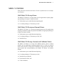
ABOUT THIS OPERATOR’S GUIDE
WHO SHOULD READ THIS BOOK?
This book is intended for new and experienced operators. If you are going to
set up, use, or maintain a Series 150 Printer with any point-of-sale system, then
this book is for you.
WHAT IS COVERED IN THIS BOOK?
This book only covers the Series 150 Printer, not the entire point-of-sale
system, but it will tell you all you need to know about using the printer
properly. You will learn what supplies you need to order, how to set up and test
the printer, and how to do the common tasks listed here:
♦ Change the paper;
♦ Print (validate) on a slip or form;
♦ Change the ribbon cassette;
♦ Change the print head;
♦ Correct problems; and
♦ Clean the printer.
This book also provides some general and technical information about the
printer, so you will know what its features are, how reliable it is, and what its
printing capabilities are.
2
Series 150 Operator’s Guide
WHERE CAN YOU FIND MORE INFORMATION?
A Programmer’s Guide is available if you need to know how to program a
point-of-sale terminal or a personal computer to work with the printer. It
describes the commands the printer recognizes to perform its functions.
A Maintenance Manual is also available It shows how to repair the Series 150
Printer and lists the replacement parts. The Maintenance Manual is intended
for trained, service technicians.
For information about ordering these books, refer to the next section.
CONTACTING
TRANSACT
TECHNOLOGIES’
ITHACA FACILITY
Contact the Ithaca facility for general information about the Series 150 Printer
and how it works with your system. The Sales and Technical Support
Departments will be able to help you with most of your questions. Call the
Technical Support Department to receive technical support; order
documentation; receive additional information about the Series 150 Printer; or
send in a printer for service. To order supplies; receive information about other
Ithaca products; or obtain information about your warranty, contact the Sales
Department.
About the Series 150 Printer
3
You may reach both the Sales and Technical Support Departments at the
following address and telephone or fax numbers:
TransAct Technologies Incorporated
Ithaca Facility
20 Bomax Drive
Ithaca, NY 14850 USA
Telephone
Main fax
Sales fax
Technical Support fax
Web site
(877) 7ithaca or (607) 257-8901
(607) 257-8922
(607) 257-3868
(607) 257-3911
http://www.transact-tech.com
WARRANTY INFORMATION
OPTIONS
All Ithaca PcOS (personal computer, point-of-sale) Series 150 Printers come
with a standard 24-month warranty covering both parts and labor that starts
upon shipment from the factory. An optional warranty, covering both parts and
labor for an additional 12 months, may be purchased separately.
For more information concerning the warranty options, please contact the Sales
Department at TransAct’s Ithaca facility. See “Contacting TransAct
Technologies’ Ithaca facility” on page 2.
SERVICE INFORMATION
TransAct Technologies is a full service organization designed to meet all
of your printer service and repair requirements. If your printer needs
service, please directly contact the Ithaca facility’s Technical Support
Department. See “Contacting TransAct Technologies’ Ithaca facility” on
page 2. Please have the model and serial numbers of the printer
available. The numbers are on a decal located on the bottom of the
printer.
4
Series 150 Operator’s Guide
TransAct offers the following service programs to meet your needs: Extended
Warranties, Depot Repairs, Maintenance Contracts, and Internet Support.
ORDERING SUPPLIES
You may order supplies by calling the Ithaca facility or by faxing the order
form that was shipped in the box with the printer. The fax number is (607) 2573868. If you would like more forms, call Transact Technologies’ Ithaca facility
at (877) 7ithaca or (607) 257-8901, and ask for the Sales Department.
The following items may be ordered:
♦ Paper,
♦ Ribbon cassettes,
♦ Take-up spools,
♦ Print heads, and
♦ Cables.
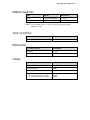
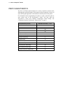
PAPER
Paper
Type
Dimensions
Stock Number
Receipt Paper
Single-ply
Width: 3.25 inches (82.6 mm)
Diameter: 3.5 inches (88.9 mm)
Length: 240 feet (73.2 m)
100-1667
Receipt-Journal
Paper
Double-ply
Width: 3.25 inches (82.6 mm)
Diameter: 3.5 inches (88.9 mm)
Length: 125 feet (38.1 m)
98-0558
Receipt-Journal
Paper
Triple-ply
Width: 3.25 inches (82.6 mm)
Diameter: 3.5 inches (88.9 mm)
Length: 85 feet (25.9 m)
06-0720
About the Series 150 Printer
RIBBON CASSETTES
Color
Supplier
Stock Number
Black
TransAct Technologies
100-7565
Purple
TransAct Technologies
100-7859
Note: Your warranty may be voided if other than genuine Ithaca
ribbons are used.
TAKE-UP SPOOLS
Take-up Spool
Stock Number
Journal Take-up Spool
90-6415
Print Head and Clamp
Stock Number
Print Head
S90-7337
Print Head Clamp
06-0571
Cables
Stock Number
110V Power Cable
06-0561
230V Power Cable
06-0806
Parallel Communication Cable
253-9800007
Serial Communication Cable
PC, 9-pin Female to 9-pin Female
PC, 9-pin Female to 25-pin Female
10-2020
10-2021
PRINT HEAD
CABLES
5
6
Series 150 Operator’s Guide
DESCRIPTION OF THE SERIES 150 PRINTER
The PcOS Series 150 Printer is a stand-alone, 40-column, high-speed impact
printer. The Series 150 Printer performs a variety of functions in a point-of-sale
environment and is available in the following models:
♦ Model 151: Receipt only
♦ Model 152: Receipt and Journal
♦ Model 153: Receipt and Validation (with or without journal)
About the Series 150 Printer
7
SERIES 150 MODELS
Each of the three models in the Series 150 line of printers has its own unique
set of features.
PcOS Model 151 Receipt Printer
The Model 151 Printer is a receipt printer used for applications requiring highspeed printing of receipts. Its features include:
♦ 340 characters per second bidirectional printing and
♦ 41-column printing at 17 characters per inch.
PcOS Model 152 Receipt and Journal Printer
The Model 152 Printer is a receipt and journal printer used for applications
requiring a transaction audit trail (journal) in addition to high-speed printing of
receipts. Its features include:
♦ 340 characters per second bidirectional printing,
♦ 41-column printing at 17 characters per inch, and
♦ Journal take-up.
PcOS Model 153 Receipt, Journal, and Validation Printer
The Model 153 Printer is a receipt and validation printer (with or without
journal) used for applications requiring printing of up to 15 lines on inserted
forms such as checks or charge slips. In addition, it can provide the same highspeed journal and receipt printing as the Model 152 Printer. Its features
include:
♦ 340 characters per second bidirectional printing,
♦ 41-column printing at 17 characters per inch,
♦ Journal take-up (optional),
♦ Form insertion sensor, and
♦ 15-line validation.
8
Series 150 Operator’s Guide
STANDARD FEATURES
The following features and items are standard on all Series 150 Printers:
♦ Centronics parallel interface with 6K buffer
♦ Internal International Power Supply (95 to 265 VAC)
♦ Operating controls and lights
Power On/Off switch and indicator
Paper FEED button
Forms RELEASE button
RESUME button
♦ READY, ALARM, and POWER LED’s
♦ Paper out sensor
♦ Operator controlled self-test
♦ Cash drawer connector (RJ12) and driver (24V, 1.5 amp pulse for
approximately 150 ms; drawer open/closed status reporting)
♦ Nine-pin stored energy print head
♦ Short line-seeking logic
♦ Characters and graphics
Lowercase characters with descenders
340 characters per second bidirectional printing
41-column printing at 17 characters per inch
Emphasized and enhanced print
IBM compatible all-points-addressable (APA) graphics
♦ Software-controlled vertical spacing
♦ Snap-on ribbon cassette
♦ Steel receipt tear-off bar
About the Series 150 Printer
9
OPTIONAL FEATURES
The optional features either replace a standard feature or enhance the operation
of the printer. All optional features are installed at the factory and must be
selected when the printer is ordered.
♦ RS-232C serial communication interface
♦ IEEE 1284 bidirectional parallel communication interface
♦ USB (Universal Serial Bus) - to be announced
♦ OPOS drivers
♦ Knife (Model 151)
♦ Journal cover lock
♦ Custom colors and logo
RELIABILITY
♦ Mean time between failure (except print head): 20,000 hours (Model 151)
♦ Print head life: 200 million characters
♦ Mean time to repair: 15 minutes
10 Series 150 Operator’s Guide
PRINT CHARACTERISTICS
The Series 150 Printer prints characters in a variety of pitches as shown in the
following table and print samples. Each pitch can also be printed in a variety of
styles affecting the appearance of the characters and the speed of the printer.
For information about programming the printer to print a particular pitch or
style, please refer to the Programmer’s Guide. You may order the
Programmer’s Guide from TransAct Technologies’ Ithaca facility. See
“Contacting TransAct Technologies’ Ithaca facility” on page 2.
Pitch (Characters per Inch)
Maximum Characters per Line
8
18
10
24
12
28
15
36
17.1 (Condensed)
41
20 (Super condensed)
48
24 (Super condensed)
57
5 (Double-wide)
12
6 (Double-wide)
14
7.5 (Double-wide)
18
8.5 (Condensed, double-wide)
20
10 (Condensed, double-wide)
24
12 (Super condensed, double-wide)
28
About the Series 150 Printer 11
12 Series 150 Operator’s Guide
About the Series 150 Printer 13
14 Series 150 Operator’s Guide
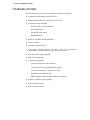
Setting Up the Printer 15
SETTING UP THE PRINTER
By following the instructions in this chapter, the Series 150 Printer should be
ready to hook up to your system in just a few minutes.
Here is a list of what is covered in this chapter:
♦ Unpacking the printer,
♦ Removing the print head carriage restraint,
♦ Choosing a location for the printer,
♦ Installing a ribbon cassette,
♦ Connecting the power cord,
♦ Loading paper,
Loading receipt paper for the Model 151
Loading receipt-journal paper for the Models 152 and 153
♦ Testing the printer, and
♦ Connecting the communication and cash drawer cables.
16 Series 150 Operator’s Guide
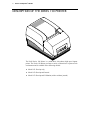
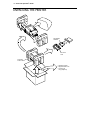
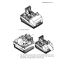
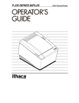
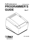
UNPACKING THE PRINTER
Print Ribbon
Cassette
AC Power
Cord
Protective
Foam Pads
• Operator's Guide
• Supplies Order Form
• Journal Lock
Keys (Optional)
Setting Up the Printer 17
Note: Be sure to save the box and packing materials in case you
need to send the printer in for service.
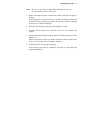
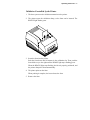
1. Before removing the printer, examine the outside of the box for signs of
damage.
If any damage has occurred to the box, carefully examine the printer and
accessories before setting up the printer. Report all evidence of damage
or abuse to your dealer and shipper.
2. Open the box and remove the papers and supplies envelope.
3. Carefully lift the printer out of the box, and set it on a sturdy, flat
surface.
4. Separate the printer from the packing material. Take the printer out of the
plastic bag.
Simply reverse these steps if you need to repack the printer to send in for
service. (You will not need to repack the supplies).
5. Check the printer for any signs of damage.
If the printer or any parts are damaged, report this to your dealer and
shipper immediately.
18 Series 150 Operator’s Guide
CHECK THAT ALL ITEMS ARE PRESENT
The following items are packed in the box and supplies envelope. If any
items are missing, contact your dealer, or if you purchased the printer
directly from TransAct Technologies, contact the Sales Department. Please
refer to “Contacting TransAct Technologies’ Ithaca facility” on page 2.
♦ PcOS Series 150 Operator’s Guide
♦ Warranty sheet
♦ Supplies order form
♦ Printer with the following items installed
Print head
Journal take-up spool assembly (Models 152 or 153 only)
♦ Journal lock keys (if journal lock was ordered)
♦ Supplies envelope
AC power cord
Ribbon cassette
♦ Paper roll (located under the paper cover)
♦ Print head carriage restraint (located under the cassette cover)
Setting Up the Printer 19
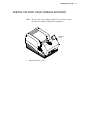
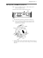
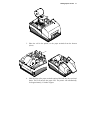
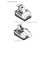
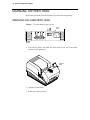
REMOVE THE PRINT HEAD CARRIAGE RESTRAINT
Note: Do not remove the packing restraints if you will be moving
the printer to another location before installation.
Cassette
Cover
1. Open the cassette cover.
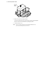
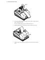
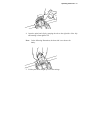
20 Series 150 Operator’s Guide
Print Head
Carriage
Restraint
2. Remove the print head carriage restraint.
The foam restraint keeps the print head from moving during shipment.
Be sure to remove the restraint before operating the printer.
3. Close the cassette cover.
Note: Save the restraint with the box and packing materials in case
you need to send the printer in for service.
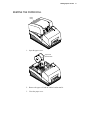
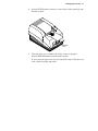
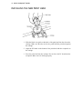
Setting Up the Printer 21
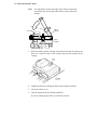
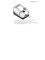
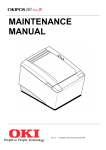
REMOVE THE PAPER ROLL
Paper
Cover
1. Open the paper cover.
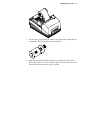
Paper Roll
Rubber Band
2. Remove the paper roll and the rubber band around it.
3. Close the paper cover.
22 Series 150 Operator’s Guide
CHOOSING A LOCATION FOR THE PRINTER
The Series 150 Printer is designed to be placed on point-of-sale terminals,
counter tops, or any other flat, stable surface that can support the weight of
the printer (about 6.5 pounds or 2.9 kg). Please refer to the dimensions when
selecting the best possible location. Be aware of the environmental
conditions of the location where you place the printer. Generally, the
environment in any store is suitable for operating the printer.
DIMENSIONS
♦ Width: 6.75 inches (171 mm)
♦ Length: 11.3 inches (287 mm)
♦ Height: 5.6 inches (142 mm)
WEIGHT
♦ Approximate weight: 6.5 pounds (2.9 kg)
♦ Approximate shipping weight: 9.5 pounds (4.3 kg)
ENVIRONMENTAL CONDITIONS
The printer will run at its best when stored and operated in an environment
that meets the following temperature and humidity conditions:
♦ Operating temperature: 0° to 50°C (32° to 122°F)
♦ Storage temperature: -10° to +60°C (-14° to +140°F)
♦ Operating relative humidity: 10% to 90% (noncondensing)
♦ Storage relative humidity: 5% to 90%
AIRFLOW
Make sure the printer is in a location where it will receive plenty of airflow.
Do not block any passages or place anything on top of the printer.
Setting Up the Printer 23
INSTALLING A RIBBON CASSETTE
Note: If you are installing the printer, a ribbon cassette can be
found in the supplies envelope.
Follow these steps to install or change the ribbon cassette.
Power
Switch
On Off
Back of
Printer
1. Turn off the printer (if already on), and open the cassette cover.
Note: If you are removing a used ribbon cassette, grasp both sides
of the cassette. Lift and rock the cassette towards you. Do
not pull the cassette straight up.
2. Holding the ribbon cassette with the Mylar guide facing away from you,
insert the front of the cassette into the carriage. See the following
illustration.
24 Series 150 Operator’s Guide
Note: It is important to fit the front edge of the ribbon cassette into
the carriage first. Do not place the ribbon cassette flat on the
carriage.
Tab
Print head
Ribbon
Cassette
Clamp
Carriage
3. Rock the ribbon cassette forward, toward the print head, and then press
down on it until the tabs on the cassette snap into the clamps on the
carriage.
4. Tighten the ribbon by turning the knob on the cassette clockwise.
5. Close the cassette cover.
6. Turn the printer back on (if already installed).
If you are setting up the printer, go to the next section.
Setting Up the Printer 25
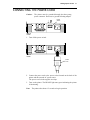
CONNECTING THE POWER CORD
Caution:
The printer must be grounded through the three-prong
power connector. Do not use a ground-defeating adapter.
Power
Switch
On Off
Back of
Printer
1. Turn off the power switch.
Back of
Printer
Power
Cord
2. Connect the power cord to the power socket located on the back of the
printer and the external AC power source.
The power cord is in the supplies envelope.
3. Turn on the printer. The READY light turns green indicating the printer
is functioning.
Note: The printer takes about 1.5 seconds to begin operation.
26 Series 150 Operator’s Guide
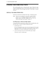
LOADING AND REMOVING PAPER
This section describes how to load and remove paper. Change the paper
when the ALARM light turns red. This indicates that the paper is low. The
printer will stop. You must change the paper for the printer to resume
operation.
INSTALL THE NEW PAPER ROLL
Follow these instructions for loading either single- or multiple-ply paper.
Note: If this is a new installation, a receipt roll is supplied with the
printer. If you are changing multiple-ply paper, remove the
journal take-up roll before loading the new roll. See
“Remove the Journal Take-up Roll” on page 34.
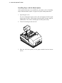
Installing Paper without the Knife Option
If your printer has the optional knife installed, refer to “Installing Paper with
the Knife Option” on page 30 for paper loading instructions.
1. Open the paper cover.
If you are changing the paper, remove the used supply roll. Do not pull
on the paper to remove unused paper from the printer. Instead, push the
FEED button. This removes unused paper from the printer safely.
2. Tear off a clean edge on the new roll, and fold the paper straight.
This makes it easier to load the paper.
Setting Up the Printer 27
3. Place the roll in the printer, so the paper unwinds from the bottom
(front).
Bail
4. Slide the edge of the paper under the optional bail and into the paper load
throat. This will activate the paper feed. The printer will automatically
feed approximately 12 inches of paper.
28 Series 150 Operator’s Guide
Take-up
Spool
5. If you are loading multiple-ply paper, place the take-up spool into the
printer, lining up the gears.
If you are loading single-ply paper, continue with Step 10.
6. Separate the paper plies. The white ply is always used for the receipt.
FEED
button
7. Fold the edge of the journal ply, and insert it into the slot on the take-up
spool.
Setting Up the Printer 29
8. Press the FEED button to wind two or three turns of the journal ply onto
the take-up spool.
RESUME
button
9. Close the paper cover, and then tear off any excess receipt paper.
Press the RESUME button to put the printer on-line.
If at any time the paper does not feed, repeat the steps. If this does not
work, remove the paper and restart.
30 Series 150 Operator’s Guide
Installing Paper with the Knife Option
If the optional knife unit is not installed on your printer, refer to “Installing
Paper without the Knife Option” on page 26 for paper loading instructions.
1. Open the paper cover.
If you are changing the paper, remove the used supply roll. Do not pull
on the paper to remove unused paper from the printer. Instead, push the
FEED button. This removes unused paper from the printer safely.
2. Tear off a clean edge on the new roll.
3. Place the roll in the printer, so the paper unwinds from the bottom
(front).
Setting Up the Printer 31
4. Open the knife unit.
Bail
5. Slide the edge of the paper under the bail (optional) and into the paper
load throat. This will activate the paper feed. The printer will
automatically feed approximately 12 inches of paper.
32 Series 150 Operator’s Guide
6. Insert the receipt (white) ply into the slot at the top of the knife unit.
7. Close the knife unit.
Setting Up the Printer 33
RESUME
button
8. Close the paper cover, and then tear off any excess receipt paper.
Press the RESUME button to put the printer on-line.
If at any time the paper does not feed, repeat the steps. If this does not
work, remove the paper and start over.
34 Series 150 Operator’s Guide
REMOVE THE JOURNAL TAKE-UP ROLL
If you are changing multiple-ply paper, you must remove the journal take-up
roll before installing the supply roll.
Paper
Cover
FEED
button
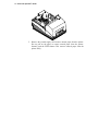
1. Open the paper cover.
2. Press the FEED button to advance the journal paper past the last journal
entry.
Setting Up the Printer 35
3. Lift the take-up spool from the printer, and cut the paper below the last
journal entry. Be sure that all entries are included.
4. Slide the printed journal off the take-up core, and put it in a safe place.
If the paper sticks on the core, hold the paper, and twist the core in the
direction opposite the way the paper is wound.
36 Series 150 Operator’s Guide
5. Remove the journal supply roll. Remove unused paper from the printer.
Do not pull on the paper to remove unused paper from the printer.
Instead, push the FEED button. This removes unused paper from the
printer safely.
Setting Up the Printer 37
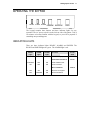
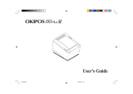
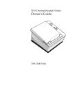
OPERATING THE KEYPAD
READY ALARM POWER
RESUME RELEASE
FEED
The keypad contains three buttons and three indicator lights for easy
operation. The AC power switch is on the left rear side of the printer. Take a
few minutes to become familiar with the keypad, so you will be prepared if
something unexpected happens.
INDICATOR LIGHTS
There are three indicator lights: READY, ALARM, and POWER. The
READY and POWER lights are green. The ALARM light is red.
READY
Light
ALARM
Light
POWER
Light
ON
OFF
ON
Condition
Printer
State
Printer is ready to print.
READY
Form Status Conditions
READY
FLASHING
OFF
ON
Insert validation form.
ON
OFF
ON
Form is inserted.
Error Conditions
OFF
ON
ON
Printer is out of paper.
OFF
FLASHING
ON
Printer has faulted.
ERROR
38 Series 150 Operator’s Guide
BUTTONS
The printer includes three buttons and a power switch, which have the
following functions:
FEED Button
The FEED button advances receipt/journal paper.
RELEASE Button
The RELEASE button is used on printers with validation capability. This
button opens and closes the forms compensation assembly, allowing forms to
be removed if a jam occurs.
RESUME Button
The RESUME button has two functions.
1. It places the printer on-line after a paper loading operation has been
completed.
2. After a printer fault has occurred, the ALARM LED will display the
error code after the RESUME button is pressed. (Refer to the
Programmer’s Guide for details.)
Note: When the printer is reinitialized, all printer functions return
to their default settings (as if the printer were just turned on),
and any data stored in the print buffer is lost. In this case,
you may need to reenter the current transaction.
AC POWER SWITCH
The AC power switch turns on the printer and puts it on-line (READY light
on, ALARM light off, POWER light on).
Note: The printer takes about 1.5 seconds to begin operation.
Setting Up the Printer 39
TESTING THE PRINTER
Test the printer to ensure that it is running properly. The sample on the
following page shows what a printout of the test may look like. The test
pattern varies depending on the printer model and the character set selected
when the printer was ordered.
Run the test after loading the paper, but before connecting it to a host system.
If the characters do not print properly or if ink is smudged on the paper,
check to make sure the paper and ribbon are installed correctly. If you are
still having problems, please refer to “Correcting Problems” on page 52.
If the printer is still not working correctly, contact your dealer or the
Technical Support Department at TransAct Technologies’ Ithaca facility. For
more information, see “Contacting TransAct Technologies’ Ithaca facility”
on page 2.
TESTING THE PRINTER
1. Turn off the printer.
2. Press and hold the RESUME button while turning on the printer.
When the printer starts printing, let go of the RESUME button.
Some technical information is printed before the self-test menu. This
information identifies the part number and date of the printer’s firmware.
If the self-test menu is incomplete or does not look at all like the sample,
contact the Technical Support Department at TransAct Technologies’
Ithaca facility. Please refer to “Contacting TransAct Technologies’ Ithaca
facility” on page 2.
40 Series 150 Operator’s Guide
The menu shown on the sample above provides different modes for running
the printer. These modes are described in the Programmer’s Guide. To order
a Programmer’s Guide, see “Contacting TransAct Technologies’ Ithaca
facility” on page 2. If you have accidentally entered this menu mode, turn the
printer off and then back on again.
Setting Up the Printer 41
CONNECTING THE CABLES
Now that you have set up and tested the printer, you are ready to connect it to
the point-of-sale system.
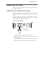
CONNECTING THE COMMUNICATION CABLE
Depending on the interface your system uses, either connect the serial or
parallel communication cable to the appropriate connector on the back of the
printer.
Cables are provided by your dealer or system installer. If cables are
unavailable, contact TransAct Technologies’ Ithaca facility. See “Contacting
TransAct Technologies’ Ithaca facility” on page 2.
Connect the Serial Cable
Back of
Printer
9-pin Serial
Interface Connector
1. Turn off the printer and host system or personal computer.
2. Connect the 9-pin serial interface cable to the connector located on the
back of the printer.
Refer to the Appendix for information on the serial cable requirements.
3. Tighten the two mounting screws on each side of the cable connector.
42 Series 150 Operator’s Guide
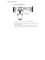
Connect the Parallel Cable
Back of
Printer
25-pin Parallel
Interface Connector
1. Turn off the printer and host system or personal computer.
2. Connect the 25-pin parallel interface cable to the connector located on
the back of the printer.
Refer to the Appendix for information on the parallel cable requirements.
3. Tighten the two mounting screws on each side of the cable connector.
Setting Up the Printer 43
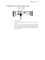
CONNECTING THE CASH DRAWER CABLES
Cash Drawer
Connector 2
Cash Drawer
Connector 1
Back of
Printer
1. Turn off the printer.
2. Connect the cash drawer cable to the connectors located on the back of
the printer.
Adapters are available for connecting cash drawers equipped with BNC
style connectors. (The standard is a modular, telephone style connector).
If you need an adapter, contact the Technical Support Department at
TransAct Technologies. See “Contacting TransAct Technologies’ Ithaca
facility” on page 2.
44 Series 150 Operator’s Guide
SETUP CHECKLIST
Did you follow all of the steps to set up the printer? Here they are again for
you to check.
❑ Unpack the printer.
❑ Remove the print head carriage restraint.
❑ Choose a location for the printer.
❑ Check the environmental conditions and the airflow around the printer.
❑ Install the ribbon cassette.
❑ Connect the power cord.
❑ Load the paper: single-ply paper on the Model 151, multiple-ply paper on
the Models 152 and 153.
❑ Test the printer.
❑ Connect the communication and cash drawer cables.
Operating the Printer 45
OPERATING THE PRINTER
Once the printer has been setup, there is very little that you need to do during
daily operation because most functions are controlled by the host system. This
chapter describes the following few tasks that you will need to perform, some
more often than others:
♦ Validating a form or slip,
♦ Changing the print head,
♦ Cleaning the printer, and
♦ Correcting problems.
Note: For instructions on changing the ribbon cassette and paper,
see the following sections:
♦ “Installing the Ribbon Cassette,” on page 23 and
♦ “Loading and Removing Paper,” on page 26.
46 Series 150 Operator’s Guide
PRINTING ON FORMS OR SLIPS
The Model 153 Printer can print on inserted forms. Inserting the form in the top
of the printer, generally referred to as validation, allows up to 15 lines of print
on a form.
VALIDATING A FORM
Forms can be validated with either a single line or multiple lines of
information. Depending on the host system and software used, either the host
system or the printer controls the procedure. In most cases, the only difference
is whether you are prompted by the host system or the printer.
Validation Controlled by the Host System
When the host system controls the validation procedure, it opens the area on
the printer where forms are inserted.
1. The host system indicates that a form is to be inserted for validation.
2. Insert the form into the printer.
3. The host system closes the validation clamp and prints on the form.
4. When printing is complete, the host system releases the form.
5. Remove the form.
Operating the Printer 47
Validation Controlled by the Printer
1. The host system sends a validation transaction to the printer.
2. The printer opens the validation clamp, so the form can be inserted. The
READY light flashes green.
READY
light
3. Insert the form into the printer.
Push the form down until it bottoms in the validation slot. Then push the
form all the way to the right until the READY light stops flashing green.
When the READY light stops flashing, the form is properly positioned, and
the printer clamps the form automatically.
4. The printer prints on the form.
When printing is complete, the host releases the form.
5. Remove the form.
48 Series 150 Operator’s Guide
CHANGING THE PRINT HEAD
Replace the print head when the characters are consistently misprinting.
REMOVING THE USED PRINT HEAD
Caution:
The print head can get very hot.
Power
Switch
On Off
Back of
Printer
1. Turn off the printer, and allow the print head to cool for at least three
minutes before replacing it.
Cassette
Cover
2. Open the cassette cover.
3. Remove the ribbon cassette.
Operating the Printer 49
4. Open the print head clip by grasping the tab on the right side of the clip
and rotating it from right to left.
Note:
In the following illustration, the heat sink is not shown for
clarity.
5. Lift the print head straight up out of the carriage.
50 Series 150 Operator’s Guide
INSTALLING THE NEW PRINT HEAD
1. Slide the black wire guide on the back of the print head into the slot on the
carriage. Make sure the tabs on the wire guide hold the print head against
the carriage.
2. Align the PC board on the bottom of the print head with the receptacle on
the carriage.
3. Press the print head into the carriage. Do not force the PC board into the
receptacle. Make sure it is lined up properly.
Operating the Printer 51
Note:
In the following illustration, the heat sink is not shown for
clarity.
4. Close the print head clip by rotating it from left to right and latching it into
place.
5. Replace the ribbon cassette, and then close the cassette cover.
6. Turn on the printer.
7. After the print head has been replaced, test the printer to make sure it is
printing properly.
52 Series 150 Operator’s Guide
CLEANING THE PRINTER
Cleaning the printer occasionally and keeping it well maintained will help it to
last longer and run better.
Caution:
Do not use rubbing alcohol or any other cleaner on the
internal parts of the printer, as some parts may crack or
break.
The internal parts of the printer do not require lubrication or routine
maintenance. Apply a common cleaner such as fantastik® or Formula 409® to a
damp cloth and gently wipe the surface of the printer and keypad.
CORRECTING PROBLEMS
INDICATOR LIGHTS SHOW A PROBLEM
READY
Light
ALARM
Light
POWER
Light
Explanation
OFF
FLASHING
ON
The printer has a fault or may have a
paper jam. Clear the jam, then power
cycle the printer.
OFF
ON
ON
The printer is out of paper. Change
the paper, so the printer can resume
operation.
Operating the Printer 53
ALARM LIGHT FLASHES RED
Any time the ALARM light is flashing red, the printer has failed.
You should first find out the code for the error that has occurred and then
attempt to correct the problem.
Press the RESUME button to display the error code. The number of times the
READY light blinks indicates the error code. Count the blinks and write down
the number. If you lose count, push the RESUME button again to redisplay the
code. You must find out the error code before turning off the printer.
After you have written down the error code, complete the following steps to
correct the problem.
1. Turn off the power switch.
2. Open the paper and cassette covers.
3. Do the following.
Remove or clear any jams or obstructions, such as misfed paper.
Turn the knob on the ribbon cassette to be sure it is operating correctly.
Move the print head from side-to-side to be sure that it slides easily.
4. Close both covers.
5. Turn on the power switch.
If you are unable to correct the problem, contact the Technical Support
Department at TransAct Technologies. Please refer to “Contacting TransAct
Technologies’ Ithaca facility” on page 2. Have the error code handy when you
call.
PRINTER SMEARS CHARACTERS
Contact the Technical Support Department at TransAct Technologies. Please
refer to “Contacting TransAct Technologies’ Ithaca facility” on page 2.
54 Series 150 Operator’s Guide
Appendix 55
APPENDIX
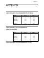
CASH DRAWER PIN ASSIGNMENTS (ITHACA)
Function
Drawer 1
Drawer 2
Drawer Drive +
Pin 4
Pin 4
Drawer Drive -
Pin 5
Pin 1
Status Signal
Pin 2
Pin 2
Status Ground
Pin 3
Pin 3
Frame Ground
Pin 6
Pin 6
No Connect
Pin 1
Pin 5
CASH DRAWER PIN ASSIGNMENTS
(EPSON/AXIOHM)
Function
Drawer 1
Drawer 2
Drawer Drive +
Pin 4
Pin 4
Drawer Drive -
Pin 2
Pin 5
No Connect
Pin 5
Pin 2
Status Signal
Pin 3
Pin 3
Status Ground
Pin 6
Pin 6
Frame Ground
Pin 1
Pin 1
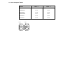
CASH DRAWER PIN ASSIGNMENTS (STAR)
56 Series 150 Operator’s Guide
Function
Drawer 1
Drawer 2
Drawer Drive -
Pin 2
Pin 2
Drawer Drive +
Pin 3
Pin 3
Status Signal
Pin 6
Pin 6
Frame Ground
Pin 1
Pin 1
No Connect
Pin 4
Pin 4
No Connect
Pin 5
Pin 5
Pin 1
Drawer 2
Pin 1
Drawer 1
Appendix 57
SERIAL CABLE
CABLE REQUIREMENTS
The PcOS Series 150 Printer requires an RS-232C shielded cable, no more than
50 feet long. The cable must be UL and CSA approved.
RS-232C COMMUNICATION
The RS-232C interface uses the following protocol and communication
characteristics:
♦ Up to 19.2 K baud,
♦ Up to 6K buffer,
♦ Ready/Busy or XON/XOFF Protocol, and
♦ Communication Diagnostic Mode.
PIN ASSIGNMENTS FOR 9-PIN PRINTER CONNECTOR
Pin
Name
Description
1
DCD
Data Carrier Detect
2
RX
Receive Data
3
TX
Transmit Data
4
DTR
Data Terminal Ready
5
GND
Signal Ground
6
DSR
Data Set Ready
7
RTS
Request To Send
8
CTS
Clear To Send
9
SSD
Secondary Data
58 Series 150 Operator’s Guide
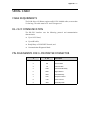
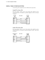
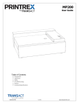
SERIAL CABLE CONFIGURATIONS
The following cable configurations are for different host requirements.
Serial PC to Series 150
Ithaca part number 10-2020, 9-pin to 9-pin female cable, should be used to
connect PcOS Series 150 Printers to personal computers or PS/2’s with 9-pin
serial ports.
Nine-pin
Female
PC
DTR
DSR
DCD
TXD
RXD
GND
RTS
CTS
PN 10-2020
Nine-pin
Female
Printer
DTR
DSR
DCD
TXD
RXD
GND
RTS
CTS
4
6
1
3
2
5
7
8
4
6
1
3
2
5
7
8
Serial AT to Series 150
Ithaca part number 10-2021, 9-pin to 25-pin female cable, should be used to
connect PcOS Series 150 printers to personal computers or PS/2’s with 25-pin
serial ports.
Twenty-f ive-pin
Female
PC
DTR 20
DSR 6
DCD 8
TXD
2
RXD 3
GND 7
4
RTS
5
CTS
PN 10-2021
Nine-pin
Female
Printer
DTR
DSR
DCD
TXD
RXD
GND
RTS
CTS
4
6
1
3
2
5
7
8
Appendix 59
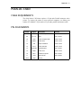
PARALLEL CABLE
CABLE REQUIREMENTS
The PcOS Series 150 Printer requires a 25-pin male D-shell connector at the
printer. To connect the printer to most personal computers, use Ithaca part
number 253-9800007, 25-pin male to 25-pin male parallel interconnect cable.
PIN ASSIGNMENTS
Pin(s)
Signal
Description
Direction
1
STROBE
Clock data to printer
Host to Printer
2-9
D0 - D7
Data
Host to Printer
10
ACK\
Printer accepted data
Printer to Host
11
BUSY
Printer busy
Printer to Host
12
PE
Paper Out/Status
Printer to Host
13
SLCT
Printer selected
Printer to Host
14
AUTOFD
Autofeed paper
Host to Printer
15
ERR\
Printer error
Printer to Host
16
INIT\
Initialize the printer
Host to Printer
17
SLIN
Select printer
Host to Printer
18-25
GND
Ground
60 Series 150 Operator’s Guide
Index 61
INDEX
A
AC power switch, 39
airflow around printer, 23
B
buttons, 39
C
cables
connecting, 42
ordering, 5
cash drawer cable
connecting, 44
cash drawer connector
pin assignments, 57
character pitch, 10
character set
sample printout, 40
cleaning, 54
D
dimensions of printer, 22
documentation
ordering. See TransAct Technologies.
E
environment of printer, 22
F
features, 8
options, 9
FEED button, 39
forms
printing, 48
I
indicator lights, 38
K
keypad
buttons, 39
indicator lights, 38
O
options, 9
ordering documentation. See TransAct Technologies.
ordering supplies, 4
P
paper
loading, 27
ordering, 4
removing, 36–37
reverse feed, 27, 31, 37
paper roll
removing, 21
parallel cable
connecting, 43
requirements, 61
parallel cable connector
pin assignments, 61
pin assignments
cash drawer connector, 57
parallel cable connector, 61
serial cable connector, 59
pitch, 10
power cord
connecting, 26
power switch, 39
print characteristics, 10
print head
changing, 50
62 Series 150 Operator’s Guide
ordering, 5
printer
cleaning, 54
dimensions, 22
environment, 22
features, 8
models, 7
options, 9
reliability, 9
repacking, 17
testing, 40
unpacking, 17
warranty, 3
weight, 22
printing
forms, 48
problems
correcting, 54
R
RELEASE button, 39
reliability, 9
repacking the printer, 17
RESUME button, 39
ribbon cassette
installing, 23
removing, 23
RS-232C communication, 59
S
serial cable
configurations, 60
connecting, 42
requirements, 59
serial cable connector
pin assignments, 59
Series 150 models, 7
service information, 3
supplies, 4
cables, 5
paper, 4
print head, 5
take-up spools, 5
T
take-up spools
ordering, 5
test printout, 40
testing the printer, 40
Transact technologies
contacting, 2
troubleshooting, 54
U
unpacking the printer, 17
V
validation, 48
W
warranty information, 3
weight of printer, 22
PN: 100-9726
Rev. F
02/03