1
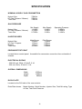
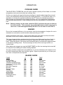
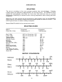
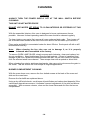
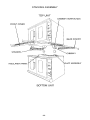
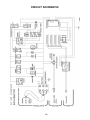
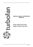
G1100 TURBOFAN OVEN
MANUFACTURED BY
Moffat Limited
PO Box 10001
Christchurch
New Zealand
Ph:
(03) 389 1007
Fax:
(03) 389 1276
WORLD-WIDE BRANCHES
UNITED KINGDOM
Blue Seal
67 Gravelly Business Park
Gravelly Park
Birmingham
West Midlands
B24 8TQ
Ph:
(121) 327 5575
Fax:
(121) 327 9711
UNITED STATES
Moffat Inc
3765 Champion Blvd
Winston-Salem
North Carolina 27115
Ph:
(336) 661 0257
Fax:
(336) 661 9546
CANADA
Serve Canada
22 Ashwarren Road
Downview
Ontario M3J1Z5
Toll Free:800 263 1455
Ph:
(416) 631 0601
Fax:
(416) 631 0315
[email protected]
www.servecanada.com
www.moffat.com
NEW ZEALAND
Christchurch
Moffat Limited
PO Box 10-001
16 Osborne Street
Christchurch
Ph:
(03) 389 1007
Fax:
(03) 389 1276
Auckland
Moffat Limited
4 Waipuna Road
Mt Wellington
Auckland
Ph:
(09) 574 3150
Fax: (09) 574 3159
AUSTRALIA
Victoria New South Wales
Moffat Pty Limited
740 Springvale Road
Mulgrave, Melbourne
Victoria 3171
Ph:
(03) 9518 3888
Fax:
(03) 9518 3838
Moffat Pty Limited
3/142 James Ruse Drive, Rose Hill
PO Box 913, Smithfield
Sydney, N.S.W. 2142
Ph:
(02) 8833 4111
Fax: (02) 8833 4133
Western Australia
Moffat Pty Limited
67 Howe Street
Osbourne Park
WA 6017
Ph:
(08) 9202 6820
Fax:
(08) 9202 6836
Queensland
Moffat Pty Limited
30 Prosperity Place
Geebung, Brisbane
Queensland 4034
Ph:
(07) 3630 8600
Fax
(07) 3630 8623
The reproduction or copying of any part of this manual by any means whatsoever is strictly forbidden unless authorized previously in
writing by the manufacturer.
In line with policy to continually develop and improve its products, Moffat Ltd. reserves the right to change the specifications and
design without prior notice.
© Copyright Moffat Ltd. September 2013
G1100 TURBOFAN OVEN
CONTENTS
PAGE
INTRODUCTION
1
SPECIFICATION
2
INSTALLATION
DOUBLE UNITS
5
OPERATION
- OVEN TEMP
- ROAST 'N HOLD
- INSTANT HOLD
- WATER
- LIGHTS
- COOKING GUIDE
- BAKING
- BAKING GUIDE
- ROASTING
- ROASTING GUIDE
7
7
7
7
7
8
8
8
9
9
CLEANING
10
FAULT DIAGNOSIS
11
SERVICING
- GAS CONVERSION
- BURNERS
- ELECTRICAL
12
12
13
SPARES
16
DOUBLE UNIT ASSEMBLY
18
CIRCUIT SCHEMATIC
19
Date Purchased....................................................................... Serial No...................................................
Dealer..........................................................................................................................................................
Service Agent..............................................................................................................................................
232479-3
INTRODUCTION
We are confident that you will be delighted with your TURBOFAN OVEN, and it will
become the most valued appliance in your kitchen.
Your new oven may seem very complex and confusing at first glance. To ensure you
receive the most benefit from your new turbofan, there are two important things you can
do.
Firstly
Please read the instruction book carefully and follow the directions given. The time taken
will be well spent.
Secondly
If you are unsure of any aspect of the installation, instructions or performance of your
oven, contact your BLUE SEAL dealer promptly. In many cases a phone call could
answer your questions.
THIS APPLIANCE IS FOR PROFESSIONAL USE AND IS ONLY TO BE USED
BY QUALIFIED PEOPLE
FOR YOUR SAFETY:
DO NOT store or use gasoline or other flammable vapours or liquids in the vicinity of this or any
other appliance.
DO NOT spray aerosols in the vicinity of this appliance while it is in operation.
Improper installation, adjustment, alteration, service or maintenance can cause
property damage, injury or death. Read the installation, operating and maintenance
instructions thoroughly before installing or servicing this equipment.
DO NOT operate the oven without the legs supplied fitted.
-1-
SPECIFICATION
NOMINAL HOURLY GAS CONSUMPTION
Natural Gas
LP Gas (Propane / Butane)
Town Gas
73MJ/hr
73MJ/hr
73MJ/hr
GAS PRESSURE
Natural Gas
LP Gas (Propane / Butane)
Town Gas
Min Supply
1.13kPa
2.75kPa
0.75kPa
Max Supply
5.0kPa
5.0kPa
2.0kPa
Main Burner
2.00mm
1.30mm
1.20mm
4.50mm
Pilot Runner
1.10mm
0.50mm
0.50mm
2.00mm
Operating Pressure
0.90kPa
2.50kPa
0.16kPa
INJECTOR SIZES
Natural Gas
LP Gas / Propane
Butane
Town Gas
PRESSURE TEST POINT
Located below control panel. Accessible for manometer connection from underside of
chassis.
ELECTRICAL RATING
- 230-240 volt, 50Hz, 1P+N+E, 2.1A
- 220 volt, 60Hz, 1P+N+E, 2.1A
OVERALL DIMENSIONS
Width
Height
Depth
1005mm
1390mm
980mm
DATA PLATE
Located on the R/H side of the oven exterior.
Data Plate shows:
Model Number, Serial Number, Injector Size, Total MJ rating, Type
of Gas, Test Point Pressure.
-2-
SPECIFICATION
G1100
1005
60
930
50
310
MWS
280
205
MWS
1
E
1390
E
135
70
Front
MWS
660
715
1
Side
1
E
Plan
-3-
SPECIFICATION
G1100 - 2
1005
60
930
50
310
MWS
MWS
GAS
E
1
E
1690
245
1
GAS
MWS
205
MWS
GAS
280
GAS
E
1
E
135
70
Front
MWS
230
285
1
Side
1
E
GAS
Plan
-4-
INSTALLATION
This appliance must be installed in accordance with National installation codes and in
addition, in accordance with relevant National / Local codes covering gas and fire safety.
AS5601 / AG601
- Gas Installations.
Australia:
New Zealand: NZS 5261
- Gas Installations.
Australia/NZ
AS / NZS 3000
- Wiring Rules.
AS / NZS 3500
- Plumbing and Drainage.
Installations must be carried out by authorised persons only. Failure to install equipment
to relevant codes and manufacturers specifications in this section will void warranty.
BEFORE CONNECTION
Unpack oven and check for damage. Report any damage to the carrier and dealer.
Report any deficiencies to your dealer.
To Fit Legs - Single Unit
Tilt the oven over on one side and fit both the front and rear legs to the side now off the
ground. Fit them into the base frame under the chassis base and secure to the base with
the bolts, spring washers and flat washers provided. Lift up the other side of the oven, fit
legs, bolts and washers, but do not tighten yet. Position leg tray (flat side facing up)
between legs and secure with 4 screws provided, then tighten all leg bolts. Level the
oven by adjusting the feet.
To Fit Legs - Double Unit
Fit and secure 4 short legs onto the bottom unit by the method described above. NOTE:
There is no leg tray for the double unit. Lay the top unit on its side and fit the spacers
provided to the base of the oven.
Lift the top unit onto the bottom unit and secure around the spacer panel flanges with selftapping screws provided. Fit chimneys over the duct assembly of the bottom unit. Screw
in place and pull down chimney surrounds onto the duct assembly. Level the oven by
adjusting the feet.
WATER CONNECTION
A cold water supply should be fitted to the water inlet which is located at the rear of the
unit. The water pressure must be as follows;
Min:
150kPa (22psi)
Max:
250kPa (23psi)
To access the water solenoid, remove the 14 screws securing the rear cover panel, and
remove the cover panel.
Fit ½" (13mm) flexible hose to the solenoid and secure with a hose clamp. Unscrew tap
(ACW) as far as possible. Turn on water supply to check for leaks. NB: It may be
necessary to hold the water injection button in for a few seconds to remove air from the
system after initial instalment.
GAS CONNECTION
Operating pressure is regulated at the gas control for both Natural and LPG gases.
Unscrew the regulator screw cap to access the regulator adjustment screw. With the
burners on, adjust the regulator spring setting until the correct operating pressure is
obtained.
Refer to the rating plate for correct operating pressure values.
It is important that adequately sized piping run directly to the connection join on the oven,
-5-
INSTALLATION
with as few tees and elbows as possible to give maximum supply volume.
An accessible shut off valve must be fitted on the supply line before the connection joint.
A suitable jointing compound which resists the breakdown action of LPG must be used
on every gas line connection.
For a DOUBLE UNIT, all gas connections must be made separately.
Check all connections for leakage. DO NOT USE A FLAME.
Note:
All gas fitting on the oven, and supply must be by a licensed Gas Fitter.
ELECTRICAL CONNECTION
The ovens electrical supply is via a 2m cord set flex at the rear of the oven. For
immediate electrical supply , simply plug the lead into a properly earthed 3 pin socket.
WARNING - THIS APPLIANCE MUST BE EARTHED
If supply cord is damaged, it must be replaced by a suitably qualified person in
order to avoid a hazard.
VENTILATION
Proper ventilation is essential for good operation. It is important to have at least 100mm
(4") of air space around both sides and rear of the oven. It is also necessary to consider
a 300mm (12") space on the RH side to gain access to circuitry and gas connections
through the access panel. However, if space is limited the minimum of 100mm (4") must
still be maintained though the oven can be moved to gain access.
COMMISSIONING
Before leaving the new installation, check correct connections have been made, and that
the unit operates in accordance with the OPERATING INSTRUCTIONS.
Note: If for some reason it is not possible to get the appliance to function
correctly, then contact the supplier.
Note: Shut off the gas supply before any maintenance work is done on the
appliance.
-6-
OPERATION (AUTO ELECTRIC IGNITION)
THIS APPLIANCE IS FOR PROFESSIONAL USE AND IS ONLY TO BE USED BY
QUALIFIED PEOPLE
Simply switch on the power at the mains switch, the MAINS pilot light is on when power is
supplied to the oven. Ignition of the oven burner is automatic when the OVEN CONTROL
is turned to the required temperature. The burners can be observed through the
inspection slots in the front shroud below the doors. If the burners fail to ignite, set the
OVEN CONTROL to "0" and then again to the required temperature. This repeats the
ignition process.
Note: It is not uncommon to have three attempts at ignition in a cold oven. Once
the oven is warmed up even slightly, ignition will be immediate.
The red HEATING light shows when the burner is "ON". When it goes out, the oven has
reached the required temperature.
To turn the oven "OFF" simply turn the OVEN CONTROL to "0" or switch off the MAINS.
Note: If for some reason, abnormal operation (different from above) is noticed,
then turn off the appliance and contact the service agent.
BAKE TIMER
This 60 minute clockwork timer is completely independent of the oven control. To set
timer, turn knob clockwise to the required time. At any stage, the time can be adjusted in
either direction. When the timer reaches the TIME UP position, the TIME UP light will
come on and a buzzer will sound. Turn timer to the OFF position to cancel the buzzer
and TIME UP light. Initially this control may be stiff to operate but will improve with use.
ROAST'N HOLD TIMER
This 3 hour timer is electrically driven and is set by turning the knob in either direction, to
the required time. The timer can be set when convenient, but will not start working until
the OVEN CONTROL is set and the ROAST'N HOLD is switched to START.
When the timer reaches the HOLD position the oven is turned off and a PRE-SET HOLD
thermostat located behind the control panel will control the oven to keep the food warm at
serving temperature as long as required until the ROAST'N HOLD is switched to OFF.
Note: The HOLD light will be on when the timer reaches HOLD until the ROAST'N
HOLD switch is turned OFF. The hold light may come on briefly when the
roast'n hold control is first switched on until the oven heats up beyond the
pre-set hold temperature.
INSTANT HOLD
To use HOLD immediately without operating the oven to cook food, set the oven control
to ON and switch ROAST'N HOLD to START.
WATER
To compensate for the loss of moisture from breads and other product while baking,
water can be injected into the oven while baking. Use a pulse time of 1-5 seconds as
required to suit the product being cooked.
LIGHTS
To turn on the two oven lights located at the rear of the oven, push the button. The lights
will remain on while the button is held in. This will enable cooking progress to be checked
without the need to open the door. To improve visibility when loading or unloading the
oven, the lights will automatically come on when the door is opened, and go off when the
door is closed.
-7-
OPERATION
COOKING GUIDE
This BLUE SEAL TURBOFAN oven will cook a greater quantity of food faster, at a lower
temperature and more evenly than an ordinary oven.
As the oven opening is large and because loading to capacity takes longer than normal
ovens, the temperature will drop during the loading operation. To off-set this effect, it is
desirable to increase the preheat temperature by 25o above the desired temperature.
After loading is completed the thermostat should be set to the appropriate temperature
for the goods being cooked. Keep loading times as short as possible to minimise heat
loss.
Note: Before cooking, set the oven control to 250oC and leave the oven to heat up
for half an hour. This removes any undesirable fumes which may be in a
new oven. It will take approximately 25 mins. for the oven to reach 250oC.
BAKING
Due to the increased efficiency of a convection oven the temperature of recipes for use in
standard non-convection ovens should be decreased by up to 50oC
Always load each shelf evenly. Space pans away from each other and from the sides
and back of the oven to allow a maximum air-flow between them.
The large tempered glass windows plus the interior oven lights permit a close check on
the goods, making it unnecessary to frequently open the oven doors and hence lose
heat. Check the goods in the oven more frequently than in conventional ovens because
of the shorter cooking times. The time savings run from 20% to as high as 50% on
certain foods.
When baking we suggest you use the BAKE TIMER, as this is a warning device and will
not stop the oven heating for further cooking batches.
As many excellent recipe books are published, it is not our intention to list recipes, but to
provide a temperature and time chart as a guide. Space is provided for you to note your
own time or temperature as required.
BAKING GUIDE
FOOD
Custard Pies
Sponge Puddings
Yorkshire Puddings (Lrg)
Yorkshire Puddings (Sml)
Meringues
Meringue Toppings
Biscuits
Sponge Cakes
Scones
Yeast Rolls
Danish Rolls
Sweet Rolls
Hamburger Buns
Yeast Bread
°F
°C
TIME
300
370
370
370
230
320
430
340
390
320
355
300
320
320
150
190
190
190
110
160
220
170
200
160
180
150
160
160
30-45 mins
10 mins
30-45 mins
10 mins
75 mins
8-10 mins
5-6 mins
15-20 mins
10-15 mins
10-15 mins
10 mins
10-15 mins
20 mins
20-25 mins
-8-
OPERATION
ROASTING
The hot air circulating in the oven reduces moisture loss and shrinkage. Turbofan
roasting times are reduced by approximately 10 mins per pound. The ROAST'N HOLD
system will automatically cook food for a set time, then hold the oven at a preset
temperature indefinitely to maintain food at serving temperature after cooking has been
completed.
When the oven has reached the set temperature, place food in oven, set the ROAST'N
HOLD timer to the required cooking time and switch ROAST'N HOLD to START. The
HOLD light will come on when cooking is complete.
Switch ROAST'N HOLD off for normal oven control.
ROASTING GUIDE
_____________________________________________________
MEAT,
Suggested
Suggested
POULTRY, FISH
Temperature °C
Time Minutes
_________________________________________________________
Beef (12lb)
Lamb (12lb)
Turkey (24lb)
Spring Chicken
Chicken Pieces
Braising
Sausages
Beef Rounds (45lb)
Steaks
Meat Loaf (4½x9)
Hamburger Patties
Bacon
Fish Fillets (4oz froz)
Fish Fingers (1oz froz)
Steak Pie
205° for 30 min then 175°
205° for 30 min then 150°
150°
175-190°
180°
150°
175°
110°
230°
150°
205°
205°
245°
205°
205°
METRIC CONVERSION
-9-
120
150
150-180
10
40-45
20-25
15-25
9 hours
10-14
45-60
4-8
6-10
20-25
10
30
CLEANING
CAUTION:
ALWAYS TURN THE POWER SUPPLY OFF AT THE WALL SWITCH BEFORE
CLEANING
THIS UNIT IS NOT WATER PROOF.
DO NOT USE WATER JET SPRAY TO CLEAN INTERIOR OR EXTERIOR OF THIS
UNIT.
With the enamelled interiors, this oven is designed to be as maintenance free as
possible. However for best operating results the oven should be cleaned regularly
To clean interior oven parts, first remove all oven racks and side racks. Then loosen off
the 4 knurled head screws at the rear of the oven and lift the fan baffle up to remove it.
Place racks and baffle in annomiated water for about 25mins. Scrub parts off with a stiff
bristled brush and dry.
Note:
When cleaning the fan, take care not to damage it, as it is properly
balanced when assembled at the factory.
To remove OVEN LAMP GLASS, simply unscrew anti-clockwise, clean and replace, but
do not overtighten. Keep liquids away from the light sockets. If there is hardened food
spillage in the oven, sprinkle the affected areas with salt, set the oven control to operate
until the affected areas have charred. Then scrape clean with a spatula or blunt knife.
When cleaning the exterior stainless steel panels, take care not to rub across the grain in
the metal. This will ensure the oven keeps its original appearance.
BURNER COMPARTMENT CLEANING
With the oven doors oven, remove the four slotted screws at the back of the oven and
slide out the oven base.
Remove the fan baffle as explained above.
Using a dry stiff bristle brush, scrub loose all paint flakes and carbon/soot deposits (if the
carbon/soot deposits are severe, it indicates incorrect adjustment of the pilot and burner
assembly). With a vacuum cleaner, clean out the loose flakes and dirt from the burner
compartment.
-10-
FAULT DIAGNOSIS
FAULT
THE OVEN DOES NOT
OPERATE / START
NO HEAT / BURNER NOT
WORKING
POSSIBLE CAUSE
REMEDY
The mains isolating switch on the
wall, circuit breaker or fuses are
“off” at the power board.
Turn on.
The power switch on the oven is
off.
Turn on switch. Power indicator
will illuminate.
Gas supply not turned on.
Turn on gas supply
Incorrect gas pressure setting for
burner.
Set correct pressure.
Burner ignition spark faulty.
Refer service section.
Burner flame not being sensed.
Refer service section.
Ignition / burner control box faulty.
Replace.
Gas valve faulty.
Replace.
FAN DOESN’T OPERATE
OVEN LIGHT NOT
ILLUMINATING
Thermostat not on.
(Fan only operates when the
thermostat is on).
Turn thermostat on.
Door not closed.
(Fan only operates when the
door is closed).
Close door.
Door microswitch out of
adjustment.
Adjust microswitch.
Blown bulb.
Replace.
NO WATER INJECTION / STEAM Water not turned on.
SLOW RECOVERY
DOORS DO NOT CLOSE
Turn water on at water supply.
Oven water nozzle blocked.
Remove, clean or replace.
Oven in ‘Roast ‘n Hold’ mode.
Switch off ‘Roast ‘n Hold’.
Overloading of oven.
Reduce oven loading.
Fan not working.
Check fan operation.
Tray in way of door.
Correctly position tray in rack.
Door catch setting incorrect.
Adjust.
Door chain setting incorrect.
Adjust.
-11-
SERVICING
GAS CONVERSION
This product is suitable for use on Natural or LPG gases. To convert from one gas type
to another the following steps must be taken:
Ensure electrical and gas supplies are turned ‘Off’.
Remove racks, side racks and fan baffle.
Unscrew 4 large screws along bottom of rear oven wall.
Slide out oven base plate.
Remove two tile clamp plates to allow removal of the two ceramic tiles.
Remove tiles.
Unscrew and remove pilot cross tube running over main burners.
Remove holding screw at end of main burners(4) and slide burner off injector.
Screw out injectors and replace with correct size for gas type:
Main Burner
Pilot Runner Tube
LPG / Propane
Burane
Natural
Town Gas
LPG (Propane / Butane)
Natural
Town Gas
1.30mm.
1.20mm
2.00mm.
4.50mm.
0.50mm.
1.10mm.
2.00mm
NOTE: Check adjustment of electronic ignition rods above burner after reassembling. Applicable to units with S/N 941 and above.
Gap required between Spark (kinked) & Earth (centre) 3-5mm.
Gap required between Earth & Main Burner 7-10mm.
NOTE: Set test point pressure at gas control to:
LPG (Propane / Butane)
Natural
Town Gas
2.50kPa
0.90kPa
0.16kPa
WARNING:
After replacing injectors test gas joints for leaks with soapy water solution. Do
not use a naked flame to test gas joints for leaks .
BURNER AERATION
All gas adjustments should be carried out by an authorised person.
Primary air shutters may need adjustment for best blue flame Conditions.
To adjust the main burner aeration to achieve the best performance, open the oven doors
fully, remove racks, side racks and fan baffle, and slide out the oven base after removing
the four screws at the rear of the oven.
With the main burners on, adjust the primary air shutters at the front of each burner until
optimum flame condition is established. Ideally flame should be blue / green in colour,
exhibit no yellow tipping and no lifting of burner ports.
Always check gas pressures when conducting gas adjustments, at the pressure test point
under control panel. (See data plate for correct pressures).
-12-
SERVICING
BURNER REPLACEMENT
To replace either main burner or the pilot cross tube burner follow steps listed under GAS
CONVERSION until the point is reached when the burner can be replaced.
Always ensure burners are correctly fitted over injectors.
ELECTRICAL
Always ensure oven is disconnected from mains supply
MOTOR AND FAN ASSEMBLY REPLACEMENT
Ensure the oven is disconnected from the mains.
Unscrew the four knurled head screws and remove the fan baffle. Remove the eight
screws retaining the fan and motor mounting plate situated on the oven back. The fan
and motor assembly can now be pulled into the oven sufficiently to disconnect the wiring.
The fan motor unit can then be removed from the oven.
To remove the fan, slacken the two socket head grub screws spaced at 90o on the fan
boss. The fan can now be removed. If trouble is experienced, use of a fan puller is
recommended. Reassembly is the reversal of the above procedure. No lubrication of
either the fan or motor is required as they are both self-lubricating.
OVEN LIGHT REPLACEMENT
Unscrew the four knurled head screws and remove the fan baffle. To replace a blown
bulb, unscrew the glass covers anti-clockwise. The bulb is a 40 watt Minature Edison
Screw bulb. Screw on lamp glass cover clockwise. Access to the light wiring is by
removing the back panel. To access the light switch, remove the screw holding the
control panel closed and open the control panel.
IGNITION CONTROL BOX REPLACEMENT
Ensure power is off to the oven. Remove the side service panel from the RH side panel.
The ignition pack and wiring will now be exposed. Replace the faulty components as
required, ensuring correct rewiring to the schematic at the back page. When servicing is
completed, replace the service panel securely.
IGNITION ELECTRODES
If ignition of the gas burners is unreliable or delayed, it could be because there is a fault
with the ignition electrodes found next to the R/H main burner under the oven base. To
observe correct operation of the ignition system firstly remove the oven internals,
including the ceramic tiles, as described under GAS CONVERSION. Remove R/H
exterior panel. Turn on the electrical supply. (Gas supply off). Turn on the oven
thermostat. A sparking cycle should be observed at the end of the spark (kinked) and
earth (centre) electrodes.
If not, check electrode gapping and adjust if necessary.
Between SPARK (kinked) and EARTH (centre) 3-5mm
Between EARTH and main burner 7-10mm
Between SENSOR and EARTH 10-12mm
Between SENSOR and main burner 7-10mm
If gapping is correct but there is no spark at electrodes then the H.T. electrical circuit
should be checked for shorts, providing the ignition control box is functioning correctly. If
there are any shorts in the electrode assy, i.e. in the electrode insulators or terminal block
then it is suggested that the assy be replaced rather than repaired to guarantee faultless
repair.
-13-
SERVICING
To remove and replace electrode assy, remove the screw holding the electrode
positioning bracket to the housing on the inside of the oven. The electrode assy can then
be drawn out of the oven from the R/H side after removing the two screws securing the
mounting bracket to the insulation panel. To replace reverse procedure. Ensure to
correctly set electrode gapping when installing new electrodes and test before fully reassembling oven.
GAS CONTROL VALVE REPLACEMENT
Ensure electrical and gas supplies are disconnected. Remove R/H side panel.
Disconnect 5-pin plug from gas control. Disconnect main gas supply pipe from the
s/steel flexible connection to manifold. Unscrew the gas control mounting bracket from
side panel and loosen pipe clamps at rear of oven. Remove the supply pipe assembly.
On work bench remove the gas control and replace. Refit the supply pipe assembly into
oven in reverse order. Reconnect the 5-pin electrical plug. Leak test the appliance.
THERMOSTAT REPLACEMENT
The thermostat fitted to this oven cannot be calibrated. If faulty, replace. Open control
panel, remove thermostat knob, unscrew thermostat from control panel. Remove fan
baffle from inside oven to allow access to the thermostat sensing bulb at rear of oven.
Unclip sensing bulb from its mounts and feed back through rear of oven. Remove
thermostat from oven. Replace with new thermostat using reverse procedure.
'HOLD' THERMOSTAT REPLACEMENT
This thermostat is present to 70oC and is used for the 'Cook'n Hold' feature. It is mounted
remotely behind the control panel. To replace follow same procedure as for main oven
thermostat.
SWITCH AND INDICATOR LIGHT REPLACEMENT
Release the screw and swing open the control panel. Disconnect the wires from the
faulty component. Press in the locking tabs on the sides of the component and press the
component out. Fit the new component by the reversal of the above procedure. Connect
the wires to the new component and check for the correct connections against the wiring
schematic on the rear panel of the unit or back page of this book.
PILOT LIGHT REPLACEMENT
Open the control panel as previously described. Detach the pilot light wires and push the
pilot light forward out of the control panel. Fit the replacement then reattach the wires.
TIMER REPLACEMENT (60 MIN)
Open the control panel as previously described. Remove the knob from the timer.
Unscrew both screws from the front of the control panel and remove the timer from the
back to replace with a new one.
TIMER REPLACEMENT (3 HOUR)
Open the control panel as previously described. Remove the knob from the timer.
Unscrew the locking nut on the front of the timer and remove the timer from the back to
replace.
BUZZER REPLACEMENT
Remove R/H side panel. Disconnect wires from buzzer found secured to insulation
panel. Replace buzzer and reconnect wires. Refit side panel.
-14-
SERVICING
DOOR ADJUSTMENTS
In the event of the doors not closing properly i.e. the RH door not closing slightly ahead of
the LH, proceed as follows to adjust. Remove bottom shroud and striker plate at front
base of the oven, secured by 4 screws on top face and one screw at either side, pull the
shroud forward until it is clear. The chain and sprocket mechanism will now be exposed.
Slacken off the locknuts on both turn-buckles and adjust each turn-buckle until the doors
close properly.
Note:
A very slight adjustment can make a considerable difference in door
closure.
Refit bottom hingle shroud and striker plate.
BROKEN GLASS REPLACEMENT
Open the doors and on the affected door remove the screws on the sides, top and bottom
edges. If it is a RH door, remove the extra screws and ball catches.
Remove the two screws on the door front.
Lift off the door outer, making sure that glass spacer and undamaged glass pane do not
fall out. Remove all glass fragments, the glass spacer and the undamaged pane. The
seals on the door inner and outer must be replaced with new ones if damaged. Replace
the broken pane and refit both clean panes either side of the spacer against the seal on
the door catches if it is a RH door. To facilitate the replacement of BOTH glass panes
follow the same procedure as above.
BALL CATCH - REPLACEMENT AND ADJUSTMENT
To replace the ball catch assembly, remove both screws and fit new replacement
assembly. To adjust the ball catch, loosen the locknut by one turn. Use the adjuster
plate provided with the oven to rotate the ball catch clockwise or anti-clockwise, moving it
into and out of the door respectively. Tighten the locknut to secure the new adjustment.
MOTOR LUBRICATION
The motor used in this oven is self-lubricating and does not require any routine
lubrication.
-15-
SPARE PARTS
The supplier will be able to offer quicker service if parts are ordered by their correct name
and part number. If the part is not in the list below, please quote the model and serial
number and a description of the part required.
NAME
PART NO.
Electrical Components
Oven Lamp Bulb
Oven Lamp Glass
Fan
Motor - 50 Hz
Motor - 60 Hz
Oven Thermostat
- Knob
60 Minute Timer
- Knob
3 Hour Timer - 50Hz
3 Hour Timer - 60Hz
- Knob
Indicator Light (yellow)
Roast Switch
Water Switch
Light Switch
Pilot Light
Microswitch
Buzzer
Pre-set Hold Thermostat
Ignition Box
Ignition Box (from Ser No. 335978 onwards)
Ignition Box (UK only)
Ignition Electrode Assembly
Water Solenoid Valve
013521
003002
017960
010148
025762
011987
015563
011760
015560
011419
011983
015567
013542
013543
012895
013891
013528
017928
011794
018223
237150
237149
018730
SA1310
012781
Gas Components
Main Burner
Pilot Runner Tube
Gas Control - 50Hz
Gas Control - 60Hz
Main Burner Injector (x4)
LPG / Propane
Butane
Nat. Gas
Town Gas
Pilot Burner Injector (x1)
LPG (Propane / Butane)
Nat. Gas
Town Gas
012185
011907
022594
SA1710
032130
032120
032200
032450
033050
033110
033200
-16-
SPARE PARTS
NAME
PART NO.
Oven
Oven Base - without Drain Hole
Oven Rack
LH Oven Rack Support
RH Oven Rack Support
Fan Baffle
Phial Guard
Ceramic Tile
Fan Puller (spares only)
011036
017824
017822
017823
004096
017961
013555
016800
Doors
Glass Pane
Door Glass Seal
Ball Catch
Ball Catch Adjuster
Ball Catch Plate
Handle End Cap
Handle
Linkage Rod
Turnbuckle - with Hook
Chain
Striker Plate
002137
090200
011005
011786
016402
018081
018131
013911
014012
017966
010254
Exterior Panels
Control Panel
Bottom Shroud
004654
011810
-17-
STACKING ASSEMBLY
-18-
CIRCUIT SCHEMATIC
-19-