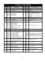
1
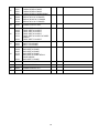
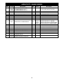
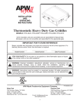
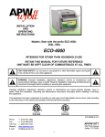
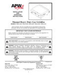
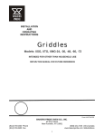
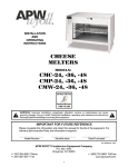
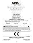
INSTALLATION AND OPERATION MAINTENANCE
APW WYOTT SERIES – RANGE OWNER’S MANUAL
Models: 24APW4BS20, 36APW6BS30, 60APW10BS26,
60APW6BG24S26, 60APW6BRG24S26
All equipments manufactured by APW wyott for use with the type of gas specified on the rating plate
and for installation will be in accordance with National Fuel Gas Code ANSI Z223.1 (latest edition)
FOR YOUR SAFETY: Do not store or use gasoline or other flammable vapors or
liquids in the vicinity of this or any other appliance.
WARNING: Improper installation, adjustment, alteration, service or maintenance
can cause property damage, injury or death. Read the installation, operating and
maintenance instructions thoroughly before installing or servicing this equipment.
Instruction to be followed in the event the user smells gas shall be posted in a prominent location. This
information shall be obtained by consulting the local gas supplier.
PLEASE RETAIN THIS MANUAL FOR FUTURE REFERENCES.
This equipment is design engineered for commercial use only.
P/N 315314 04/11
Phone : (214) 421-7366
Fax : (214) 565-0976
Toll Free : (800) 527-2100
Website : www.apwwyott.com
E-mail : [email protected]
APW WYOTT
Foodservice Equipment Company
729 Third Avenue, Dallas, TX 75226
1
TABLE OF CONTENTS
Installation Instructions........................................................................................................................... 2
Operating Instructions ............................................................................................................................ 3
Maintenance Instructions ....................................................................................................................... 3
Cleaning and Maintenance .................................................................................................................... 7
Exploded View –APW wyott series......................................................................................................... 9
Parts List – APW wyott series .............................................................................................................. 10
Exploded View – APW wyott series...................................................................................................... 11
Parts List – APW wyott series .............................................................................................................. 12
Warranty ............................................................................................................................................. 13
INSTALLATION INSTRUCTIONS
Installation of the equipment should be performed by qualified, certified, and authorized personnel
who are familiar and experienced with local installation codes.
Before Installation please read instructions completely and carefully.
Do not remove permanently affixed labels, warnings or plates from the product.
SHIPPING DAMAGE CLAIM PROCEDURE
The equipment is inspected and crated carefully by skilled personnel before leaving our factory. The
transportation company assumes full responsibility for safe delivery upon acceptance of this
equipment. If shipment arrives damaged:1. Visible loss or damage: Note on freight bill or express delivery and signed by person making
delivery.
2. File claim for damages immediately: Regardless of extent of damages.
3. Concealed loss or damage: If damage is noticed after unpacking, notify Transportation
Company immediately and file “Concealed Damage” claim with the transportation carrier. This
should be done within fifteen (15) days from the date delivery and receipt of goods. Retain
container for inspection.
Please observe all local and national codes and ordnances.
Installation must conform with local codes, or in the absence of local codes, the National Fuel Gas
Code, ANS1 Z223.1 (latest edition).
In Canada, installation should conform to installation codes for gas burning appliances and
equipment standard CAN/CGA-B149.1 or the Propane installation code, CAN/CGA-B149.2, as
applicable.
Electrical wiring to the appliance must be electrically grounded in accordance with local codes or in
the absence of local codes with the National Electrical Code ANSI/NFPA 70, or the Canadian
Electrical Code, CSA C22.2, as applicable.
A manual gas shut-off valve must be installed in the gas supply line ahead of the appliance and gas
pressure regulator for safety and ease in servicing.
The gas pressure regulator supplied must be installed on the appliance prior to connecting the
equipment to the gas line. Failure to install a regulator could be potentially hazardous and will void
the appliance warranty.
The appliance and its individual shut off valve must be disconnected from the gas supply piping
system during any pressure testing of that system at test pressures in excess of ½ psi (3.45kpa).
The appliance must be Isolated from gas supply piping system, by closing its individual manual shut
off valve during any pressure testing of the gas supply piping system at test pressures equal to or
less than ½ psi (3.45kpa)
2
OPERATION INSTRUCTIONS
Operation of this equipment must be performed by qualified or authorized personnel who have read and
are familiar with the functions of the equipment.
MAINTENANCE INSTRUCTIONS
RATING PLATE
The rating plate is located in front of the range below the oven section. Information on this plate
includes the model, serial number, BTU / hour input of the burners, operating gas pressure in inches
WC, and whether the appliance is orificed for natural or propane gas. Pilot lighting instructions (ovens
only) are also located in the same area. The Salamander broiler, or Cheesemelter (if provided) are
supplied with their own rating plates.
When communicating with factory about a unit or requesting for special parts or information, rating plate
data is essential for proper identification.
APW WYOTT COOKING APPLIANCES MUST BE CONNECTED ONLY TO THE TYPE OF GAS
IDENTIFIED ON THE RATING PLATE
CLEARANCES
The appliance area must be kept free and clear of all combustibles.
The clearances from combustible and non combustible construction of ranges and range mounted
salamander broiler or cheese melter are as follows.
Back
Sides
Combustible
4"
10"
Non combustible
0
0
If legs or casters are not used, the appliance must extend 2" beyond the front edge of a non
combustible curb or platform.
HIGH SHELF ASSEMBLY
Mount the high shelf Assembly to the range with # 10 sheet metal screws.
If a Salamander broiler / Cheese melter is to be mounted on Range, read installation instructions
for Salamander / Cheese melter before installing the High Shelf. Care must be taken to ensure
gas supply piping and / or gas supply regulator is not exposed to exhaust gases, or elevated
temperatures.
LEVELLING (Ranges equipped with Ovens)
A carpenter’s spirit level should be used and placed on the oven’s center baking rack and or across the
range top and the unit leveled from front to back and side to side. If it is not level, cakes, casseroles and
any other liquid or semi liquid batter will not bake evenly, burner combustion may be erratic, and the
unit will not function efficiently.
If the floor is smooth and level, the appliance may be further leveled with adjustment in the foot of the
leg. Units with castors require adjustment with shims. A unit will probably not return to the same position
after being moved, requiring relevelling after each and every move.
3
AIR SUPPLY & VENTILATION
The area in front of, around and above the appliance must be kept clear to avoid any obstruction of the
flow of combustion and ventilation air. Adequate clearance must be maintained around the appliance for
easy servicing.
Provision should be made for any commercial, heavy duty cooking appliance exhaust combustion
waste products to the outside of the building. Usual practice is to place the appliance under an exhaust
hood, which should be constructed in accordance to the local codes.
Strong exhaust fans in this hood or in the overall air conditioning system can produce a slight vacuum in
the room and / or cause air drafts, either of which can interfere with the pilot or burner performance and
could be difficult to diagnose. Air movement should be checked during installation. Air openings or
baffles may have to be provided in the room, if pilot or burner outrage problem persists.
GAS CONNECTION
The gas supply (service) line must be the same size or greater than the inlet line of the appliance.
APW wyott ranges and ovens use a ¾" NPT inlet. Sealant on all pipe joints must be resistive to LP gas.
MANUAL SHUT OFF VALVE
This installer supplied valve must be in the gas service line ahead of the appliance regulator in the gas
stream and in a position accessible in the event of an emergency.
PRESSURE REGULATOR
Commercial cooking equipment must have a pressure regulator on the incoming service line for safe
and efficient operation, since service pressures may fluctuate on local demand. A pressure regulator is
packed inside every APW wyott range.
Failure to install the pressure regulator will void the appliance warranty.
The regulators supplied along with APW wyott appliances, will have ¾" inlet/outlet openings and are
adjusted at the factory for 5" WC (natural gas) or 10" WC (propane gas) depending on customer's
ordering instructions.
Prior to connecting the regulator, check the incoming line pressure, as these regulators can only
withstand a maximum pressure of ½'' psi (14" WC). If the line pressure is beyond this limit, a step down
regulator will be required.
The arrow shown on the bottom of the regulator body shows the gas flow direction, it should point
downstream to the appliance. The red air vent cap on the top is part of the regulator and should not be
removed.
Any adjustments to the regulator should be made by qualified service personnel only with the proper
equipment.
CONNECTIONS
Please check installer supplied intake pipes visually and / or blow them with compressed air to clear
any dirt particles, threading chips or any other foreign matter before installing a service line. When gas
pressure is applied, these particles could clog orifices.
All connections must be sealed with a joint compound suitable for LP gas, and all connections must be
tested with a soapy water solution before lighting any pilots.
4
FLEXIBLE COUPLINGS, CONNECTOR AND CASTERS
For an appliance equipped with casters, the installation shall be made with a connector that complies
with the Standard for Connectors for Movable Gas Appliances, ANSI Z21.69 or Connectors for
Moveable Gas Appliances, CAN/CGA-6.16, and a quick disconnect device that complies with the
Standard for Quick Disconnect Devices for Use With Gas Fuel, ANSI Z21.41, or Quick Disconnect
Devices for Use With Gas Fuel, CANI-6.9.
If disconnection of the restraint is necessary, make sure to reconnect restraint after the appliance has
been returned to its originally installed position. Domestic gas or water connectors are not suitable.
Restraining device may be attached to the back frame / panel of the unit.
If the appliance is to be installed with casters, a flexible connector must be used and the same ANSI
standards apply. Locking front casters are provided to limit the movement of the appliance without
depending on the connector or associated piping. A suitable strain relief must be installed with a flexible
connector.
All connections must be sealed with a joint compound suitable for LP gas and all connections must be
tested with soap water solution before lighting pilots.
INITIAL PILOT LIGHTING
CAUTION: When lighting pilots and checking for leaks, do not stand with your
face close to the combustion chamber.
All APW wyott appliances are adjusted and tested before leaving the factory, effectively matching them
to sea level conditions. Adjustments and calibrations to assure proper operation may be necessary on
installation to meet local conditions, low gas characteristics; correct possible problems caused by rough
handling or vibration during shipment and are to be performed only by qualified service personnel.
These adjustments are the responsibility of the customer and / or dealer and are not covered by our
warranty.
Check all gas connections for leaks with a soapy water solution before lighting any pilots.
DO NOT USE ANY FLAME TO CHECK FOR LEAKS
Before lighting any pilots, make sure that burner valves and thermostats are turned "OFF".
TOP BURNERS / RAISED GRIDDLE / BROILER
All top section burners are equipped with constant burning pilots. These are to be manually lighted
immediately after the gas is turned on and the system is checked for leaks. Burner pilots are provided
for each burner and can be rechecked for proper adjustment. All adjustments can be made with a screw
driver to the brass pilot valve accessible through the valve cover.
GRIDDLE
The pilot should be lighted immediately after the gas is turned on and the system is checked for leaks.
The pilot can be reached with a long match through the valve cover, or by lifting the plate upward and
accessing through the top. Adjustment of the pilot flame can be made with a screwdriver to the pilot
valve, accessible through the valve cover.
5
STANDARD OVEN
Pilot gas is tapped from the main burner manifold pipe, routed through tubing to a safety valve, and
then to a pilot burner. Gas flow is controlled by the safety valve.
Oven pilot lighting or relighting is to be completed as follows:
Turn the thermostat knob to "OFF" position and wait for 5 minutes.
Open the oven’s lower kick plate by lifting up and out. This exposes the pilot valve and the
igniter button.
Make sure accumulated gas if any has dispersed. Since propane gas is heavier than air, check
near the floor area for the odor of propane gas before attempting to light any pilot burner.
Depress the red button on the safety valve and hold it in, throughout the lighting procedure.
Press the red button of the pilot igniter and you should hear a snap and see a spark at the pilot
burner. If a spark or spark igniter is not present apply a lit match to the pilot burner head.
Continue to depress the safety valve button until the pilot remains lit when released.
If pilot is extinguished, repeat steps 4 through 6 above.
Turn the oven thermostat knob "ON" and set to desired temperature setting, watch to make sure
the oven burner ignites from the pilot and that there are no yellow flames from the burner.
Turn the oven thermostat to the "OFF" and replace the lower kick plate.
NOTE: It may be necessary to relight the pilot several times until the lines are purged of any trapped air
and a constant gas flow is attained.
For complete shutdown, turn all burner valves, pilot valves and thermostats to the "OFF" position. Turn
shut off valve.
BEFORE 1st USE
Griddles
Clean the griddle surface thoroughly with hot, soapy water to remove protective oil coating
applied at the factory.
Rinse with a mixture of ¼ cup vinegar to one quart water.
Spread unsalted solid shortening or liquid frying compound evenly over the entire griddle
surface.
Turn all griddle burners to medium and wait until the shortening begins to smoke, then turn the
burners "OFF".
Rub the now melted shortening into the griddle surface with burlap, moving in the direction of
the surface’s polish marks and covering the entire surface.
Allow the griddle to cool.
When the griddle is cool after the second seasoning, wipe it with a thin film of shortening or
cooking oil.
Ovens
On initial installation turn the oven to 250 degrees and operate for hour, then reset the thermostat to its
maximum and operate for another hour. This will drive off any solvents remaining in the unit. At the end
of this second hour, turn the thermostat "OFF", open the door and allow the unit to cool. Oven should
then be thoroughly washed using hot soapy water before being used.
6
CLEANING AND MAINTENANCE
Any equipment works better and lasts longer when maintained properly. Cooking equipment is no
exception. Your APW wyott range and Oven must be kept clean on a daily basis.
CAUTION: Never use Ammonia in an oven that is warmer than room temperature
and always have direct ventilation!
DAILY MAINTENANCE
OPEN BURNERS
Remove all top grates.
Lift off the burner heads and venturies by raising the head slightly, sliding to the rear of the
range and lifting upwards.
Wash all of the above in hot, soapy water.
Re-install burner parts in the reverse order.
GRIDDLES
Scrape with a nylon griddle scraper to remove cooked on spills. When absolutely necessary use
a fine grained stone to scrape.
Wipe away any griddle stone dust and food particles with burlap.
Wash with hot, soapy water, then rinse with vinegar and water.
Rinse again with clear water.
Re-oil with shortening or liquid frying compound.
DO NOT FLOOD A HOT GRIDDLE WITH COLD WATER.
This could cause warping and griddle plate to crack.
OVENS
Remove the baking racks. Wash in hot soapy water, and replace after the oven is fully cleaned.
Remove the oven bottom by lifting it out from the front, then sliding forward, out of the oven.
Scrape off any food particles with a nylon griddle scrapper. Be very careful about scratching the
porcelain finish on the oven liner panels.
Wash all the above with hot soapy water, then reassemble.
Baked on spills may be loosened and stubborn stains removed with ordinary household
ammonia and scrubbing with a nylon pad in a cold oven only.
Do not allow spray type oven cleaners to come into contact with the temperature probe in the
oven.
After the cleaning the oven, rinse well with ¼ cup of vinegar to one quart of clean water solution
to neutralize any caustic residue of the cleaning compound. Wipe dry.
PERIODIC CLEANING
Check the ventilation system periodically to see that nothing has fallen down into the stub back, high
riser or high shelf exhaust vents. Lubricate the pivot pins of the oven door hinge where the right and left
arms connect to the door. Use lubricating oil. Ensure your APW wyott range be checked by a qualified
technician once a year for efficient operation of the appliance.
7
STAINLESS STEEL
All stainless steel body parts should be wiped regularly with hot soapy water during the day and with a
liquid cleaner designed for this material at the end of each day. DO NOT USE steel wool, abrasive
cloth, or powders to clean stainless surfaces. If it is necessary to scrape stainless steel to remove
encrusted materials, soak in hot water to loosen the material, then use a wood or nylon scraper. DO
NOT USE a metal knife, spatula, or any other metal tool to scrape stainless steel. Scratches are almost
impossible to remove.
Contact the factory, factory representative or a local service company to perform all
Maintenance and Service Repairs.
8
APW WYOTT – RANGE SERIES
9
APW WYOTT – RANGE SERIES
Item
Part #
Description
Item
Part #
310382
310295
8706300
R3032A
301039
301053
301046
1
2
3
4
311016
311015
311013
314010
TOP GRATE 12" X 12"
BURNER LONG
BURNER SHORT
RACK 24" RAISED GRIDDLE
19
20
21
22
5
310119
310356
310253
20” OVEN BOTTOM
26 ½” OVEN BOTTOM
30” OVEN BOTTOM
23
310266
310133
310271
310456
310457
310389
311037
310310
310514
315710
24
310713
311810
300177
311027
318220
317412
310344
316010
311725
310896
311824
311936
390137
390139
390160
310113
340116
311010
2065847
310114
310425
310230
BURNER HANGER
24" CRUMB TRAY
36" CRUMB TRAY
RACK GUIDE ANGLE RIGHT
RACK GUIDE ANGLE LEFT
MANIFOLD 24" RANGE
MANIFOLD 36" RANGE
MANIFOLD 48” RANGE
MANIFOLD 60" RANGE
MANIFOLD 60" RANGE 24" GRIDDLE
RIGHT
MANIFOLD 24" RANGE GRIDDLE
MANIFOLD 72" RANGE
TEE 3/16 COMPRESSION
VALVE PILOT
VALVE COVER 24" RANGE
VALVE COVER 24" RAISED GRIDDLE
VALVE COVER 36" RANGE
VALVE COVER 48" RANGE
VALVE COVER 60" RANGE
VALVE COVER 60" w/24" GRIDDLE RIGHT
VALVE COVER 72" RANGE
VALVE COVER 36” SECTION RAISED GR
DOOR ASSEMBLY 20" RANGE OVEN
DOOR ASSEMBLY 26.5” RANGE OVEN
DOOR ASSEMBLY 30" RANGE OVEN
HANDLE 20" OVEN
HANDLE 26 ½” OVEN
HANDLE 30" OVEN
NAME PLATE APW WYOTT
KICK PLATE 20" OVEN
KICK PLATE 26 ½” OVEN
KICK PLATE 30" OVEN
17
318328
18
310385
310462
310517
6
7
8
9
10
11
12
13
14
15
16
301055
25
2000101
360111
Description
KNOB OVEN 425F
BEZEL THERMOSTAT KNOB
KNOB METAL
VALVE GAS
ORIFICE HOOD #34 NAT 30,000 BTU
ORIFICE HOOD #53 LP 30,000 BTU
ORIFICE HOOD #46 NAT 20,000 RAISED
GRIDDLE
ORIFICE HOOD #55 LP 20,000 RAISED
GRIDDLE
FLANGE THERMOSTAT
THERMOSTAT OVEN 425F
26
2092517
PLUG 1 /8 NPT
27
370143
FITTING STRAIGHT ¼ NPT X 3/8CC
28
29
311038
311028
MANIFOLD OVEN
ADAPTER 1 /8 MALENPT X 3 /8-27
30
301050
301056
301053
301057
ORIFICE HOOD #50 NAT 15,000 BTU OVEN
ORIFICE HOOD #56 LP 15,000 BTU OVEN
ORIFICE HOOD #53 NAT 10,000 BTU OVEN
ORIFICE HOOD #57 NAT 10,000 BTU OVEN
31
311026
BURNER STRAIGHT OVEN
32
310126
PILOT OVEN RANGE
33
310123
PIEZO MANUAL SPARK IGNITOR
34
311011
PILOT SAFETY VALVE
DRIP PAN 24” RAISED GRIDDLE
35
390210
390211
CASTER 5" PLATE
CASTER 5" PLATE WITH BRAKE
RACK 20” OVEN
RACK 26 ½” OVEN
RACK 30” OVEN
36
311039
LEG 6" STAINLESS
10
318219
315311
315911
318311
310354
310226
311029
311044
LANDING LEDGE 24" RANGE
LANDING LEDGE 36" RANGE
LANDING LEDGE 60" RNAGE
LANDING LEDGE 24" RAISED GRIDDLE
REGULATOR NAT 24"-36" RANGES
REGULATOR LP 24"-36" RANGES
REGULATOR NAT 48"-72" RANGES
REGULATOR LP 48"-72" RANGES
310345
CHANNEL SUPPORT RIGHT
310124
310235
310366
311715
315716
311814
FRONT SHEET 24" HI-SHELF
FRONT SHEET 36" HI-SHELF
FRONT SHEET 48" HI-SHELF
FRONT SHEET 60" HI-SHELF
FRONT SHEET 60" HI-SHELF w/ RAISED
GRIDDLE
FRONT SHEET 72" HI-SHELF
SHELF TOP 24" RANGE
SHELF TOP 36" RANGE
SHELF TOP 60" RANGE
BACK SHEET 24" RANGE
BACK SHEET 36" RANGE
BACK SHEET 48" RANGE
BACK SHEET 60" RANGE
BACK SHEET 60" RANGE WITH 24”
RAISED GRIDDLE
BACK SHEET 72" RANGE
43
310330
ELBOW 3/8 CC X ¼ MNPT
44
310210
THERMOCOUPLE 18"
45
310237
CHANNEL SUPPORT LEFT
46
310251
FLAME SPREADER OVEN
37
38
39
40
41
42
311813
318225
315312
315912
310125
310236
310367
311715
318313
11
APW WYOTT – RANGE SERIES
12
APW WYOTT– RANGE SERIES
Item
2
3
4
5
6
7
Part #
310492
315730
312309
318311
318321
315728
311026
314010
318328
Description
12" RAISED GRIDDLE PLATE 3/4"
24" RAISED GRIDDLE PLATE 3/4"
36" RAISED GRIDDLE PLATE 3/4"
24" LANDING LEDGE RAISED GRIDDLE
GREASE CAN RAISED GRIDDLE
RADIANT BURNER INSIDE
BURNER STRAIGHT
RACK 24" RAISED GRIDDLE
DRIP PAN 24" RAISED GRIDDLE
8
316411
CRUMB TRAY 24" RAISED GRIDDLE
24
9
10
317412
8706300
VALVE COVER 24" RAISED GRIDDLE
KNOB-GAS VALVE
11
12
13
14
15
311027
311036
310713
VALVE PILOT
PILOT TIP
MANIFOLD 24" RAISED GRIDDLE
STRAIGHT FITTING 3/8 NPT X 3/8 CC
EXTENSION ORIFICE
ORIFICIE HOOD #46 NAT 20,000 BTU
ORIFICIE HOOD #55 LP 20,000 BTU
1
16
370143
300178
301046
301055
Item
Part #
17
-
18
19
20
21
22
23
25
26
310382
310295
2000101
360111
370143
2092614
301046
301055
301050
301057
360168
311026
KNOB OVEN RANGE 425F
BEZEL
FLANGE THEROSTAT
THERMOSTAT 425F
FITTING STRAIGHT
ELBOW 3/8 CC X 3/8 -27
ORIFICE HOOD #46 NAT “U” BURNER
ORIFICE HOOD #55 LP “U” BURNER
ORIFICE HOOD #50 NAT STRAIGHT BRNR
ORIFICE HOOD #57 LP STRAIGHT BRNR
BURNER “U”
STRAIGHT BURNER
27
28
310710
315916
GREASE CAN FLAT GRIDDLE
24" FLAT GRIDDLE PLATE
13
Description
VALVE COVER CONTACT FACTORY
APW WYOTT EQUIPMENT LIMITED WARRANTY
APW Wyott Food service Equipment Company warrants it's equipment against defects in materials and workmanship, subject to the
following conditions:
This warranty applies to the original owner only and is not assignable.
Should any product fail to function in its intended manner under normal use within the limits defined in this warranty, at the option of APW
Wyott such product will be repaired or replaced by APW Wyott or its Authorized Service Agency. APW Wyott will only be responsible for
charges incurred or service performed by its Authorized Service Agencies. The use of other than APW Wyott Authorized Service Agencies
will void this warranty and APW Wyott will not be responsible for such work or any charges associated with same. The closest APW
Wyott Authorized Service Agent must be used.
This warranty covers products shipped into the 48 contiguous United States, Hawaii, metropolitan areas of Alaska and Canada. There will
be no labor coverage for equipment located on any island not connected by roadway to the mainland.
Warranty coverage on products used outside the 48 contiguous United States, Hawaii, and metropolitan areas of Alaska and Canada may
vary. Contact the international APW Wyott distributor, dealer, or service agency for details.
Time Period
One year for parts and one year for labor, effective from the date of purchase by the original owner. The Authorized Service Agency may,
at their option, require proof of purchase. Parts replaced under this warranty are warranted for the un-expired portion of the original product
warranty only.
Exceptions
*
Gas/Electric Cookline: Models HCB, HCRB, HMG, HTG, HHP, HHPS, GCB, GCRB, GF, GGM, GGT, CHP-H, EF, EG,
EHP. Three (3) Year Warranty on all component parts, except switches and thermostats. (2 additional years on parts only.
No labor on second or third year.)
* Broiler Briquettes, Rock Grates, Cooking Grates, Burner Shields, Fireboxes: 90 Day Material Only. No Labor.
* Heat Strips: Models FD, FDL, FDD, FDDL. Two (2)Year Warranty on element only. No labor second year.
* Glass Windows, Doors, Seals, Rubber Seals, Light Bulbs: 90 Day Material Only. No Labor.
In all cases, parts covered by extended warranty will be shipped FOB the factory after the first year.
Portable Carry In Products
Equipment weighing over 70 pounds or permanently installed will be serviced on-site as per the terms of this warranty. Equipment
weighing 70 pounds or under, and which is not permanently installed, i.e. with cord and plug, is considered portable and is subject to the
following warranty handling limitations. If portable equipment fails to operate in its intended manner on the first day of connection, or use,
at APW Wyott's option or its Authorized Service Agency, it will be serviced on site or replaced.
From day two through the conclusion of this warranty period, portable units must be taken to or sent prepaid to the APW Wyott Authorized
Service Agency for in-warranty repairs. No mileage or travel charges are allowed on portable units after the first day of use. If the customer
wants on-site service, they may receive same by paying the travel and mileage charges. Exceptions to this rule: (1) countertop warmers and
cookers, which are covered under the Enhanced Warranty Program, and (2) toasters or roller grills which have in store service.
Exclusions
The following conditions are not covered by warranty:
* Equipment failure relating to improper installation, improper utility connection or supply and problems due to ventilation.
* Equipment that has not been properly maintained, calibration of controls, adjustments, damage from improper cleaning and
water damage to controls.
* Equipment that has not been used in an appropriate manner, or has been subject to misuse or misapplication, neglect, abuse,
accident, alteration, negligence, damage during transit, delivery or installation, fire, flood, riot or act of god.
* Equipment that has the model number or serial number removed or altered.
If the equipment has been changed, altered, modified or repaired by other than an Authorized Service Agency during or after the warranty
period, then the manufacturer shall not be liable for any damages to any person or to any property, which may result from the use of the
equipment thereafter.
This warranty does not cover services performed at overtime or premium labor rates. Should service be required at times which normally
involve overtime or premium labor rates, the owner shall be charged for the difference between normal service rates and such premium
rates. APW Wyott does not assume any liability for extended delays in replacing or repairing any items beyond its control.
In all cases, the use of other than APW Wyott Authorized OEM Replacement Parts will void this warranty.
This equipment is intended for commercial use only. Warranty is void if equipment is installed in other than commercial application.
Water Quality Requirements
Water supply intended for a unit that has in excess of 3.0 grains of hardness per gallon (GPG) must be treated or softened before being
used. Water containing over 3.0 GPG will decrease the efficiency and reduce the operation life of the unit.
Note: Product failure caused by liming or sediment buildup is not covered under warranty.
"THE FOREGOING WARRANTY IS IN LIEU OF ANY AND ALL OTHER WARRANTIES EXPRESSED OR IMPLIED INCLUDING
ANY IMPLIED WARRANTY OF MERCHANTABILITY OR FITNESS FOR PARTICULAR PURPOSES AND CONSTITUTES THE
ENTIRE LIABILITY OF APW WYOTT. IN NO EVENT DOES THE LIMITED WARRANTY EXTEND BEYOND THE TERMS
STATED HEREIN."
14
Phone : (214) 421-7366
Fax : (214) 565-0976
Toll Free : (800) 527-2100
Website : www.apwwyott.com
E-mail : [email protected]
APW WYOTT
Foodservice Equipment Company
729 Third Avenue, Dallas, TX 75226
15