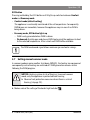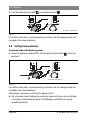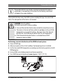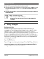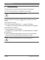
1
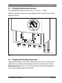
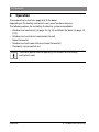
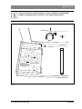
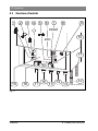
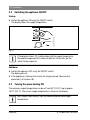
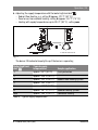
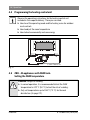
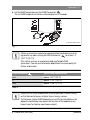
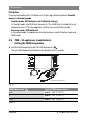
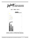
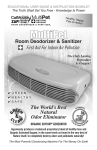
6 720 806 992-00-1O Residential Gas Condensing Boiler Greenstar 6 720 806 993 (2013/03) CA/US ZBR16/21/28/35/42-3A... | ZWB28/35/42-3A... Operating Instructions 2 | Contents Contents 1 Key to symbols and safety instructions . . . . . . . . . . . . . . . . . . . . . . . . . . . . 4 1.1 Key to symbols . . . . . . . . . . . . . . . . . . . . . . . . . . . . . . . . . . . . . . . . . . . 4 1.2 Safety instructions . . . . . . . . . . . . . . . . . . . . . . . . . . . . . . . . . . . . . . . . 5 2 Information about the appliance . . . . . . . . . . . . . . . . . . . . . . . . . . . . . . . . . . 2.1 Certifications . . . . . . . . . . . . . . . . . . . . . . . . . . . . . . . . . . . . . . . . . . . . . 2.2 Proper use . . . . . . . . . . . . . . . . . . . . . . . . . . . . . . . . . . . . . . . . . . . . . . . 2.3 Overview of boiler types . . . . . . . . . . . . . . . . . . . . . . . . . . . . . . . . . . . . 3 Preparing the appliance for operation . . . . . . . . . . . . . . . . . . . . . . . . . . . . . 8 3.1 Checking the boiler water pressure . . . . . . . . . . . . . . . . . . . . . . . . . . . 9 3.2 Topping up the heating system water . . . . . . . . . . . . . . . . . . . . . . . . . 9 4 Operation . . . . . . . . . . . . . . . . . . . . . . . . . . . . . . . . . . . . . . . . . . . . . . . . . . . . 10 4.1 Overview of controls . . . . . . . . . . . . . . . . . . . . . . . . . . . . . . . . . . . . . . 12 4.2 Switching the appliance ON/OFF . . . . . . . . . . . . . . . . . . . . . . . . . . . . 14 4.3 Turning the space heating ON . . . . . . . . . . . . . . . . . . . . . . . . . . . . . . 14 4.4 Programming the heating control unit . . . . . . . . . . . . . . . . . . . . . . . . 16 4.5 ZBR..-3A appliances with DHW tank: Setting the DHW temperature . . . . . . . . . . . . . . . . . . . . . . . . . . . . . . .16 4.6 ZWB..-3A appliances (combi boilers): Setting the DHW temperature . . . . . . . . . . . . . . . . . . . . . . . . . . . . . . .18 4.7 Setting manual summer mode . . . . . . . . . . . . . . . . . . . . . . . . . . . . . . 19 4.8 Setting frost protection . . . . . . . . . . . . . . . . . . . . . . . . . . . . . . . . . . . 20 4.9 Activating the key pad lock . . . . . . . . . . . . . . . . . . . . . . . . . . . . . . . . . 21 4.10 Display codes . . . . . . . . . . . . . . . . . . . . . . . . . . . . . . . . . . . . . . . . . . . 22 5 Thermal disinfection . . . . . . . . . . . . . . . . . . . . . . . . . . . . . . . . . . . . . . . . . . . 22 Greenstar 7 7 7 8 6 720 806 993 (2013/03) Contents | 3 6 Energy saving tips . . . . . . . . . . . . . . . . . . . . . . . . . . . . . . . . . . . . . . . . . . . . . 24 7 Troubleshooting . . . . . . . . . . . . . . . . . . . . . . . . . . . . . . . . . . . . . . . . . . . . . . . 26 8 Maintenance . . . . . . . . . . . . . . . . . . . . . . . . . . . . . . . . . . . . . . . . . . . . . . . . . . 27 9 Environmental responsibility/disposal . . . . . . . . . . . . . . . . . . . . . . . . . . . 28 10 Quick reference . . . . . . . . . . . . . . . . . . . . . . . . . . . . . . . . . . . . . . . . . . . . . . . 29 Index . . . . . . . . . . . . . . . . . . . . . . . . . . . . . . . . . . . . . . . . . . . . . . . . . . . . . . . . 30 6 720 806 993 (2013/03) Greenstar 4 | Key to symbols and safety instructions 1 Key to symbols and safety instructions 1.1 Key to symbols Warnings Warnings in this document are identified by a warning triangle printed against a grey background. Keywords at the start of a warning indicate the type and seriousness of the ensuing risk if measures to prevent the risk are not taken. The following keywords are defined and can be used in this document: • NOTICE indicates that property damage may occur. • CAUTION indicates that personal injury may occur. • WARNING indicates that severe personal injury may occur. • DANGER indicates that severe personal injury or death may occur. Important information Important information for the proper use of the boiler is also provided in this manual. You will find the information with a symbol shown on the left and bordered by horizontal lines above and below the text. Additional symbols Symbol Explanation ▶ Sequence of steps Cross-reference to other points in this document or to other documents • Listing/list entry – Listing/list entry (2nd level) Table 1 Greenstar 6 720 806 993 (2013/03) Key to symbols and safety instructions | 5 1.2 Safety instructions General information This manual is available in English and French. ▶ Keep this manual for future use. ▶ Observe the safety instructions of this manual before putting the heating appliance into operation. If the information in this manual is not followed exactly, a fire or explosion may result causing property damage, personal injury or loss of life. ▶ Do not store or use gasoline or other flammable vapors and liquids in the vicinity of this or any other appliance. ▶ What to do if you smell gas – Do not try to light any appliance. – Do not touch any electrical switch; do not use any phone in your building. – Immediately call your gas supplier from a neighbor’s phone. Follow the gas supplier’s instructions. – If you cannot reach your gas supplier, call the fire department. ▶ Installation and service must be performed by a trained and certified heating contractor, service agency or the gas supplier. If you smell gas ▶ ▶ ▶ ▶ ▶ Turn off the gas cock ( page 12). Open windows and doors. Do not operate any electrical switches. Extinguish all open flames. From outside the building, call gas utility company and a trained and certified heating contractor. If you smell flue gas ▶ Switch OFF the appliance ( page 14). ▶ Open windows and doors. ▶ Inform a trained and certified heating contractor. 6 720 806 993 (2013/03) Greenstar 6 | Key to symbols and safety instructions For appliances operating on room air: Danger of flue gas poisoning if supply of combustion air is insufficient ▶ Safeguard supply of combustion air. ▶ Do not cover or reduce the size of ventilation openings in doors, windows and walls. ▶ Safeguard sufficient supply of combustion air also for appliances installed at a later date, e.g. kitchen exhaust fans, clothes dryers, and air conditioning units with vent to the outside. ▶ Never operate the appliance if the supply of combustion air is insufficient. Danger of explosion of flammable gases. ▶ Only employ a trained and certified contractor to carry out work on the gas train. Risk of scalding ▶ If running at DHW temperatures above 104 °F (40 °C) ask a trained and certified heating contractor to install a tempering valve to prevent scalding. ▶ When the thermal disinfection function is enabled, DHW temperatures above 140 °F (60 °C) can occur. Risk of damage due to operator error Operator errors can result in personal injury and damage to property. ▶ Ensure that children never operate this appliance unsupervised or play with it. ▶ Ensure that only people who know to operate this appliance correctly have access to it. Installation, conversion Only have the appliance installed or modified by a trained and certified heating contractor. Never modify any parts that carry flue gas. Never close the outlet of safety valves. Water may be expelled from any safety valve during heat-up. Inspection and maintenance The operator is responsible for safety and environmental compliance of the heating system. Greenstar 6 720 806 993 (2013/03) Information about the appliance | 7 Sign a maintenance and inspection contract with a trained and certified contractor, covering an annual inspection and demand-dependent maintenance. This guarantees high efficiency and environmentally sound combustion. Explosive and easily combustible materials Never use or store easily combustible materials (paper, thinners, paints, etc.) near the appliance. Combustion air / room air To prevent corrosion, keep the supply of combustion air / room air free of corrosive substances (e.g. halogenated hydrocarbons that contain chlorine or fluorine compounds). Overheating of the appliance Should overheating occur or the gas supply fail to shut off, do not turn off or disconnect the electrical supply to the pump. Instead, shut off the gas supply at a location outside of the appliance. In case of water damage Do not use this boiler if any part has been under water. Immediately call a trained and certified service technician to inspect the boiler and to replace any part of the control system and any gas control which has been under water. 2 Information about the appliance 2.1 Certifications This product has been tested and certified for the US and the Canadian market and complies with all applicable standards required for the US and the Canadian market. 2.2 Proper use The appliance may only be installed in closed loop hot water central heating systems. Any other purpose is considered improper use. Any resulting damage is excluded from the manufacturer's warranty. 6 720 806 993 (2013/03) Greenstar 8 | Preparing the appliance for operation The commercial and industrial use of the appliance for generating process heat is not permitted. 2.3 Overview of boiler types Greenstar ZBR16-3A ZBR21-3A ZBR28-3A ZBR35-3A ZBR42-3A ZWB28-3A ZWB35-3A ZWB42-3A Table 2 Z W B R 16…42 -3 A 3 Central heating appliance DHW heating Condensing technology Constant temperature control Output up to 54,600 / 71,600 / 95,500 / 119,400 / 143,300 BTU/hr (16 / 21 / 28 / 35 / 42 kW) Version Fan-supported appliance Preparing the appliance for operation ▶ If existing, open the heating supply valve and the heating return valve. ▶ If existing, open the cold water valve and the DHW valve. ▶ When using ZBR..-3A appliances with DHW tank, open a DHW tap until water runs out. ▶ Open the gas cock. ▶ Open the control panel cover. Greenstar 6 720 806 993 (2013/03) Preparing the appliance for operation | 9 3.1 Checking the boiler water pressure The standard boiler water pressure is 14.5 - 21.75 psi (1 - 1.5 bar). Should a higher boiler water pressure be required, refer to a trained and certified heating contractor. 2 1 30 15 3 45 0 psi 4 bar 6 720 641 934-04.2O Fig. 1 3.2 Topping up the heating system water Topping up the heating system water is different on every system. Therefore, you should ask a trained and certified heating contractor to show you how it is done. Maximum pressure of 30 psi (2.07 bar) at maximum heating water temperature must not be exceeded (safety valve will spill). 6 720 806 993 (2013/03) Greenstar 10 | Operation 4 Operation These operating instructions apply only to the boiler. Depending on the heating control unit used, some functions may vary. The following options for controlling the heating system are available: • Outdoor reset control unit ( page 16, Fig. 6) installed in the boiler ( page 12, [19]) • Outdoor reset control unit mounted on the wall • Room thermostat • Outdoor reset with room influence (room thermostat) • Third party system control unit Therefore, please read the operating instructions for the heating control unit used. Greenstar 6 720 806 993 (2013/03) Operation | 11 Page 29 contains a quick reference. You can fold this outward and keep these operating instructions in the control panel cover. 3 2 1 4 5 6 max 6 720 614 235-04.1O Fig. 2 6 720 806 993 (2013/03) Greenstar 12 | Operation 4.1 Overview of controls 1 2 3 4 5 6 7 8 9 reset 10 eco 11 19 18 17 16 15 14 13 12 6 720 641 934-01.1O Fig. 3 Greenstar 6 720 806 993 (2013/03) Operation | 13 [1] [2] [3] [4] [5] [6] [7] [8] [9] [10] [11] [12] [13] [14] [15] [16] [17] [18] [19] Emission test button for contractors (see installation instructions) Service button for contractors (see installation instructions) Burner ON indicator lamp ON/OFF switch Key pad lock ECO button Reset button Display Boiler water pressure gauge DHW thermostat Safety relief valve discharge hose Condensate drain hose Heating return pipe Cold water pipe - combi boiler only Gas pipe DHW pipe - combi boiler only Supply pipe Boiler high limit dial Mounting socket for outdoor reset controls 6 720 806 993 (2013/03) Greenstar 14 | Operation 4.2 Switching the appliance ON/OFF Startup 3 2 1 4 5 6 max 6 720 613 896-05.1O ▶ Switch the appliance ON using the ON/OFF switch. The display shows the supply temperature. Fig. 4 If the display shows in alternation with the supply temperature, the appliance operates at its lowest output for 15 minutes per the initial startup sequence. Shutdown ▶ Switch the appliance OFF using the ON/OFF switch. The diplay goes out. ▶ If the appliance is taken out of service for a longer period: Observe frost protection ( Section 4.8). 4.3 Turning the space heating ON The maximum supply temperature can be set from 95 °F (35 °C) up to approx. 194 °F (90 °C). The current supply temperature is shown on the display. With radiant floor heating, limit the maximum permissible supply temperature. Greenstar 6 720 806 993 (2013/03) Operation | 15 ▶ Adjusting the supply temperature with the boiler high limit dial : – Radiant floor heating: e.g. setting 3 (approx. 122 °F (50 °C)) – Panel or cast iron radiator heating: setting 6 (approx. 167 °F (75 °C)) – Heating with supply temperatures up to 194 °F (90 °C): setting max reset eco 3 3 4 2 1 2 5 4 e 6 1 6 max min max 6 720 641 933-53.1O Fig. 5 The burner ON indicator lamp lights up if the burner is operating. Boiler high limit dial Typical supply temperatures Sample application 1 approx. 95 °F (35 °C) Frost protection 2 approx. 109 °F (43 °C) 3 approx. 122 °F (50 °C) 4 approx. 140 °F (60 °C) 5 approx. 153 °F (67 °C) 6 approx. 167 °F (75 °C) Radiator heating system max approx. 194 °F (90 °C) Convector heating Radiant floor heating system Table 3 Typical supply temperatures 6 720 806 993 (2013/03) Greenstar 16 | Operation 4.4 Programming the heating control unit Observe the operating instructions for the heating control unit included in the scope of delivery. There you can read: ▶ How to set the operating mode and the heating curve for outdoor reset controls ▶ How to adjust the room temperature ▶ How to heat economically and save energy 9 12 h 15 18 6 3 24 h 21 6 720 612 660-07.2O Fig. 6 4.5 ZBR..-3A appliances with DHW tank: Setting the DHW temperature DANGER: Danger of scalding! ▶ In normal operation, it is recommended to limit the DHW temperature to 122 °F (50 °C) to limit the risk of scalding. ▶ Only set temperatures up to 158 °F (70 °C) for thermal disinfection ( page 22). Greenstar 6 720 806 993 (2013/03) Operation | 17 ▶ Set the DHW temperature on the DHW thermostat . The set DHW temperature flashes on the display for 30 seconds. reset eco 3 2 1 4 3 2 5 6 max 1 4 e 6 max 6 720 641 933-54.1O Fig. 7 If there is reason for concern for contamination from bacteria such as legionella, consider setting the DHW thermostat to at least “e” (131 °F (55 °C)). This setting ensures an economical and comfortable DHW generation. Consult your local water department or municipality for further information. DHW thermostat Typical DHW temperatures min approx. 59 °F (15 °C) e approx. 131 °F (55 °C) max approx. 158 °F (70 °C) Table 4 Always set the DHW temperature as low as possible. A lower setting on the thermostat means a higher rate of energy savings. Furthermore, higher DHW temperatures result in increased limescale deposits and thereby may impair the function of the appliance (e.g. longer times for heating up or lower output). 6 720 806 993 (2013/03) Greenstar 18 | Operation ECO button Pressing and holding the ECO button until it lights up switches between Comfort mode and Economy mode. • Comfort mode, ECO button is not lit (default setting) In Comfort mode, the DHW tank has priority. The DHW tank is heated to the set temperature first. Then the appliance switches to central heating mode. • Economy mode, ECO button lit In Economy mode, the appliance alternates between central heating mode and DHW mode. 4.6 ZWB..-3A appliances (combi boilers): Setting the DHW temperature ▶ Set the DHW temperature on the DHW thermostat . The set DHW temperature flashes on the display for 30 seconds. reset eco 3 2 1 4 3 2 5 6 max 1 4 e 6 max 6 720 641 933-55.1O Fig. 8 DHW thermostat Typical DHW temperatures min approx. 104 °F (40 °C) e approx. 122 °F (50 °C) max approx. 140 °F (60 °C) Table 5 Greenstar 6 720 806 993 (2013/03) Operation | 19 ECO button Pressing and holding the ECO button until it lights up switches between Comfort mode and Economy mode. • Comfort mode (default setting) The appliance is continually maintained at the set temperature. Consequently, DHW draws are immediate, however the appliance may run even if no DHW is being drawn. • Economy mode, ECO button lights up – DHW is only generated when DHW is drawn. – On demand: Quickly open and close a DHW tap to signal the appliance to heat to the selected temperature. After a short wait DHW will be available. The DHW on demand signal allows maximum gas and water savings. 4.7 Setting manual summer mode In summer mode or warm weather shut down (WWSD), the heating zone pump and consequently central heating are switched off. DHW generation remains active following the DHW program. NOTICE: Heating system at risk of freezing. In manual summer mode, only the appliance is protected from freezing. ▶ Observe frost protection measures where there is a risk of freezing ( page 20). ▶ Make a note of the setting of the boiler high limit dial 6 720 806 993 (2013/03) . Greenstar 20 | Operation ▶ Turn the boiler high limit dial counterclockwise to . reset eco 4 3 3 5 2 1 e 2 6 1 6 max min max 6 720 641 933-82.1O Fig. 9 For further information, see the operating instructions for the heating control unit included in the scope of delivery. 4.8 Setting frost protection Frost protection of the heating system: ▶ Leave the appliance switched ON; turn the boiler high limit dial position 1. at least to reset eco 3 3 2 1 5 2 6 max 1 min 4 e 6 max 6 720 641 933-68.1O Fig. 10 For further information, see the operating instructions for the heating control unit included in the scope of delivery. Alternatively if you prefer switching the appliance OFF: ▶ Ask a trained and certified heating contractor to mix anti-freeze (see installation instructions) into the heating water. All DHW pipes and DHW tank must be completely drained. Greenstar 6 720 806 993 (2013/03) Operation | 21 Frost protection of the DHW tank: counterclockwise to min (59 °F (15 °C)). ▶ Turn the DHW thermostat reset eco 3 4 3 2 5 1 e 2 6 max 1 6 min max 6 720 641 933-69.1O Fig. 11 4.9 Activating the key pad lock The key pad lock affects the supply temperature dial, the DHW thermostat, the service button and the ECO button. Activating the key pad lock: ▶ Press the key pad lock button until alternating on the display. and the heating supply temperature are reset eco 3 2 1 3 4 2 5 6 max 1 min 4 e 6 max 6 720 641 933-83.1O Fig. 12 Unlocking the key pad: ▶ Press the key pad lock button until the display shows only the supply temperature. 6 720 806 993 (2013/03) Greenstar 22 | Thermal disinfection 4.10 Display codes Display Description Fault-Code ( chapter 7) Inspection due Pump anti-seize function active Key pad lock active Condensate trap filling function active Bleeding function active Excessively rapid increase in supply temperature (temp. gradient monitoring). Heating mode is disabled for two minutes. If this message appears repeatedly, inform a trained and certified heating contractor. Drying function. If the slab drying function is activated on the outdoor reset control unit, refer to the operating instructions for the heating control unit included in the scope of delivery. Table 6 5 Thermal disinfection When using ZBR..-3A appliances with DHW tank it may be necessary to disinfect the DHW tank and DHW system after longer idle periods to prevent bacterial contamination, for example from legionella bacteria. This step is typically not necessary if the drinking water is chlorinated or ozonated. Greenstar 6 720 806 993 (2013/03) Thermal disinfection | 23 Thermal disinfection can also be carried out automatically and on a regular basis; see operating instructions for the heating control unit included in the scope of delivery. Thermal disinfection covers the DHW system including the taps. For solar DHW tanks, the solar portion of the tank is not covered. DANGER: Risk of scalding! Hot water can result in severe scalding. ▶ Carry out thermal disinfection only outside the normal hours of use. ▶ The water in the tank will take a while to cool down to the set DHW temperature as a result of heat loss. Be aware that, after thermal disinfection, the DHW may be hotter than the set temperature. ▶ If the thermal disinfection feature is activated have a DHW tempering valve installed. Performing a manual disinfection of the DHW tank and system ▶ Close all DHW taps. ▶ Advise occupants of the risk of scalding if no tempering valve is installed. ▶ Set the time and DHW temperature accordingly on the heating control unit with DHW program. ▶ Set any DHW recirculation pump to continuous operation. ▶ Turn DHW thermostat clockwise to max (approx. 158 °F (70 °C)). reset eco 3 2 1 4 3 2 5 6 max 1 4 e 6 max 6 720 614 156-16.1O Fig. 13 6 720 806 993 (2013/03) Greenstar 24 | Energy saving tips ▶ Wait until the maximum temperature has been reached. ▶ Open all DHW taps, from the nearest to the one furthest away, and draw off DHW until water at a minimum of 158 °F (70 °C) has flown from all taps for at least 3 minutes. ▶ Reset the DHW thermostat, DHW recirculation pump, and heating control unit to standard operation. To cancel the thermal disinfection: ▶ Switch the appliance OFF and ON again. The appliance starts up again and the current supply temperature is displayed. 6 Energy saving tips Heating economically The boiler is designed to provide a high level of comfort while keeping gas consumption and the resulting environmental impact as low as possible. The gas supply to the burner is controlled according to the heat demand. The boiler continues to operate on low fire if the demand for heat drops. The technical term for this process is modulating control, and it reduces temperature fluctuations and provides even distribution of heat throughout the home. This means that the boiler may stay on for relatively long periods but will use less gas than an appliance that continually cycles on and off. Inspection/Maintenance To ensure that gas consumption and environmental impact (pollution, etc.) remain as low as possible over an extended period of time, we recommend that you sign an inspection/maintenance contract with a trained and certified heating contractor covering scheduled annual service and maintenance. Greenstar 6 720 806 993 (2013/03) Energy saving tips | 25 Heating control unit Use a heating control unit with room temperature influence or an outdoor reset control unit and thermostatic valves. For further information, see the operating instructions for the heating control unit included in the scope of delivery. Thermostatic valves Fully open the thermostatic valves to ensure that the desired room temperature is reached in all cases. Allow several days for the system to stabilize after every adjustment and only change the setting for the heating curve or the room temperature on the control unit after the system had stabilized on the previous settings. Radiant floor heating Do not set the supply temperature higher than the maximum level recommended by the manufacturer. Room venting Do not keep windows cracked for ventilation purposes as it continuously cools down the room without significantly improving the air quality in the room. It is better to vent fully for a short time (with completely open windows). Turn off the thermostats (if installed) in the room when venting. Domestic hot water (DHW) Always set the DHW temperature as low as possible. A lower setting on the thermostat means a higher rate of energy savings. Furthermore, higher DHW temperatures result in increased limescale deposits and thereby may impair the function of the appliance (e.g. longer heating-up times or lower output). Recirculation pump If there is a DHW recirculation pump installed, use a timer program to control its operation according to the specific requirements (e.g. morning, afternoon, evening). 6 720 806 993 (2013/03) Greenstar 26 | Troubleshooting 7 Troubleshooting The Heatronic boiler control monitors all safety and control components. If a fault arises during operation, an audible warning tone sounds. Press a button to mute the warning sound. The display indicates a fault code (e.g. flashing. ) and the reset button may also be If the reset button is flashing: ▶ Press the reset button and hold it until appears on the display. The appliance starts up again and the current supply temperature is displayed. If the reset button is not flashing: ▶ Switch the appliance OFF and ON again. The appliance starts up again and the current supply temperature is displayed. If the fault persists: ▶ Contact a trained and certified heating contractor for assistance, providing details of the fault code and the appliance type and serial number. An overview of the display codes can be found on page 22. Greenstar 6 720 806 993 (2013/03) Maintenance | 27 Appliance details If you need to call a trained and certified heating contractor, you may be asked for details on your appliance. Those details can be found on the rating plate. Greenstar (e. g. ZBR 28-3 A ...): ........................................................................................................ Serial number: ........................................................................................................ Date commissioned: ........................................................................................................ System installed by: ........................................................................................................ 8 Maintenance Inspection and maintenance The operator is responsible for the safety and environmental compatibility of the heating system (see local regulations). It is therefore recommended to sign a maintenance and inspection contract with a trained and certified heating contractor that provides annual inspection and maintenance. This ensures high efficiency and environmentally compatible combustion. Cleaning the outside of the boiler and the control unit Wipe down with a damp cloth. Do not use any abrasive or corrosive cleaning agents. 6 720 806 993 (2013/03) Greenstar 28 | Environmental responsibility/disposal 9 Environmental responsibility/disposal Environmental responsibility is one of the fundamental company policies of the Bosch Group. We regard quality of performance, economy and environmental responsibility as equal objectives. Environmental protection laws and regulations are strictly adhered to. To protect the environment, we use the best possible technology and materials taking into account economic points of view. Packaging For packaging, we participate in the country-specific recycling systems, which guarantee optimal recycling. All packaging materials used are environmentally-friendly and recyclable. Old appliances Old appliances contain materials that should be recycled. The components are easy to separate and the plastics are marked. This allows the various components to be sorted for appropriate recycling or disposal. Greenstar 6 720 806 993 (2013/03) Quick reference | 29 10 Quick reference DHW temperature Startup 6 720 613 896-05.1O 4 3 5 2 1 DANGER: Danger of scalding! ▶ In normal operation, it is recommended to limit the DHW temperature to 122 °F (50 °C) to limit the risk of scalding. 6 max Turning space heating ON reset eco 3 2 1 3 4 2 5 reset 4 e eco 6 1 6 max min max 3 6 720 641 933-53.1O 4 2 e 1 6 Heating control 4 3 2 5 1 6 max max 6 720 641 933-55.1O Set outdoor reset heating control unit to the relevant heating curve and operating ECO button lit – Economy mode. ECO button not lit – Comfort mode. mode or set room thermostat to the desired temperature. Frost protection Key pad lock reset eco reset 3 3 eco 2 1 5 2 6 max 3 2 1 4 3 5 2 6 max 1 min 4 e 1 min 4 e 6 max 6 720 641 933-68.1O 6 max 6 720 641 933-83.1O 6 720 806 993 (2013/03) Greenstar 30 | Index Index C Certifications.............................................................................................. 7 Cleaning the outer casing ........................................................................... 27 Commissioning ........................................................................................... 8 D Details about the appliance - proper use ............................................................................................ 7 - type overview........................................................................................ 8 DHW temperature ................................................................................16, 18 Disinfection.............................................................................................. 22 Disposal................................................................................................... 28 E ECO button ........................................................................................ 18–19 Energy saving tips ..................................................................................... 24 Environmental responsibility....................................................................... 28 F Fault codes............................................................................................... 26 Faults ...................................................................................................... 26 Frost protection ........................................................................................ 20 G General information..................................................................................... 5 H Heating control ......................................................................................... 16 I Information about the appliance .................................................................... 7 Greenstar 6 720 806 993 (2013/03) Index | 31 K Key pad lock..............................................................................................21 M Maintenance .............................................................................................27 O Old appliances ..........................................................................................28 Operation .................................................................................................10 Overview of controls ..................................................................................12 P Packaging .................................................................................................28 Proper use ..................................................................................................7 R Recycling..................................................................................................28 S Safety instructions .......................................................................................5 Summer mode...........................................................................................19 Supply temperature ...................................................................................14 Switching the appliance OFF .......................................................................14 Switching the appliance ON.........................................................................14 T Thermal disinfection............................................................................... 6, 22 Type overview .............................................................................................8 6 720 806 993 (2013/03) Greenstar