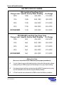
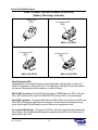
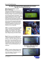
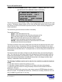
1
“ALL ABOUT BATTERIES & MORE” Visit the Technical Zone @ www.invacare.com Technical Phone Support 1-800-832-4707 Service & Parts Education DEEP CYCLE GELL BATTERIES How does a Gel Cell Work? A Gel cell is a “recombinant” battery. This means that the oxygen that is normally produced on the positive plate in all lead-acid batteries recombines with the hydrogen given off by the negative plate. The “recombination” of the hydrogen and oxygen produces water (H20), which replaces the moisture in the battery. Therefore, the battery is maintenance-free, as it never needs water. Source: MK Battery Technical Manual, www.mkbattery.com DOES THE DEPTH OF THE DISCHARGE AFFECT CYCLE LIFE? YES! The greater the load on the batteries, the sooner they will have to be replaced. *Typical Gel Cell Cycling Ability vs. Depth of Discharge Capacity Withdrawn Typical Life Cycles 100% ........................................................ 300 *75% ........................................................ 450 50% ......................................................... 650 *75% is the average capacity withdrawn for an active user. *NOTE: Consumers may experience longer or shorter battery life, depending on charging habits, temperature, and accessories in the system. Source: MK Battery Technical Manual, www.mkbattery.com Course # 1 Manual Rev. 1/02 page # 2 1 Service & Parts Education WHEELCHAIR BATTERIES WHAT CONSUMERS NEED TO KNOW ABOUT BATTERIES (courtesy of MK Battery) Battery Size: Always follow the manufacturers recommendations for battery size. Battery Type: Always use Deep Cycle batteries, due to the fact that they are designed to be discharged and recharged on a regular basis. Cold Cranking Amp or Marine type batteries are for starting purposes only, and are not intended for electronic type vehicles. Lead Acid vs. Gel Cell Batteries: Gel Cell batteries are the safest choice due to FAA and DOT regulations, and are recommended by most manufacturers. Gel Cell batteries require less maintenance than Lead Acid batteries, and are the safest choice for your consumer. Chargers and Charging: Use the manufacturers charger on all models, and no more than 8 amps MAX. Never allow the batteries to be run completely down, Deep Cycle batteries do not have a memory. Avoid topping off batteries with frequent short charges, it will do more harm than good. Once a recharge cycle begins, allow it to run for the duration until the charger shuts itself off. Transportation: All GEL MK batteries are approved for public and private transportation. See there website for more details @www.mkbattery.com. Storing Batteries: All batteries should be stored with a full charge, and it is a good idea to disconnect the main power source to avoid possible discharging. Course # 1 Manual Rev. 1/02 page # 3 2 Service & Parts Education BATTERY CARE & SAFETY Do Don’t Don’t perform any installation or maintenance without first reading the service manual. Read and understand the service manual and any service information that accompanies a battery and charger before working on the wheelchair or scooter. Don’t perform installation or maintenance of batteries in an area that could be damaged by battery spills. Move the wheelchair to a work area before or opening battery boxes, checking the fluid level, adding distilled water, and cleaning terminals. Don’t tell your clients to run the batteries completely down before recharging. You can recharge as frequently as possible to maintain a high charge level for extended battery life. Don’t put new batteries into the field without charging them first. Fully charge new batteries before use, to verify that the batteries and charging system are working properly. Don’t tip or tilt Lead Acid batteries. Use a carrying strap to remove or carry batteries, when ever possible. Don’t use ordinary tap water to top-off Lead Acid batteries. ONLY use distilled water to top-off Lead Acid batteries. Don’t overfill Lead Acid battery cells. Fill Lead Acid battery cells just to split-ring level. Don’t tap on clamps with hammers or any other tools to pry open. Push the battery clamps onto the terminals, and use terminal spreader tool to open clamps. Don’t charge Lead Acid batteries when the Dual Mode charger is in the Gel Setting, and vice versa. Use a Fully Automatic Dual Mode charger for best charging results. Don’t set batteries on concrete. It is no longer true that setting batteries on concrete surfaces will discharge them. Don’t believe that Deep Cycle batteries have a memory. Deep Cycle batteries do not have a memory. Don’t store power mobility vehicles for long periods with the batteries discharged. Recharge the batteries and disconnect them from the controller before storing the PMV for long periods of time. Don’t believe that Marine batteries will work on power mobility vehicles. Do use batteries that state they are approved for electronics type vehicles, and are deep cycle. Rubber Gloves Carrying Strap Distilled Water Course # 1 Manual Rev. 1/02 page # 4 Tools & Safety Items Safety Glasses Shop Apron Insulated Wrenches Terminal Spreaders Wire Brush Cleaning Solvent 3 Service & Parts Education REPLACING WHEELCHAIR BATTERIES Do you replace a set of batteries every time a customer says there bad? Before you do replace a pair of batteries, make sure you have accurately diagnosed the problem first. STOP! BEFORE YOU REPLACE YOUR NEXT SET OF BATTERIES, READ THIS INFORMATION Battery Testing Procedure: 1. Use your Digital Volt Meter to read the static battery voltage. A fully charged set of gel batteries will read at least 25.6 volts and above. 2. If the batteries are not fully charged, try to recharge them overnight before replacing them. Severely discharged batteries could take up to 10 to 16 hours to reach a 100% full charge. Severely discharged batteries could also rise rapidly, and give the charger a false reading causing the OEM charger to shut off too soon. If the batteries are too low for the OEM charger to begin, remove the batteries from the battery boxes, and use a 12 volt charger (no more than 10 AMPS) on each battery for an hour. Then put the batteries back into the battery boxes, and recharge them overnight with the OEM charger. 3. Once the batteries are fully charged, perform a field load test or use your programmer to check the Battery Quality Menu. 4. If the batteries are determined to be bad, replace the batteries. If the batteries check out good, then your problem lies elsewhere. Check the motors and the chairs electronics for further problems. Course # 1 Manual Rev. 1/02 page # 5 4 Service & Parts Education BATTERY CONNECTIONS “SERIES CIRCUIT” A “series” system increases the voltage, but keep the battery capacity the same. Therefore, two 12-volt batteries connected in series (POS to NEG, NEG to POS) will deliver 24-volts at the same rating as one battery. During recharge, each battery will recieve the same amount of current (AMPS). Series hookup increases voltage. 2 x 12 Volts = 24 Volts Series Connection Example (Single Battery Box w/ 22NF Batteries) Negative - Positive + Positive + Negative - TECHNICIANS NOTE: Depending on the make and model of the product, the batteries may be in individual battery boxes. In this case the connections are much easier, one positive connection (RED +) and one negative connection (BLACK -). Course # 1 Manual Rev. 1/02 page # 6 5 Service & Parts Education **BATTERY SIZES CHART Power Chairs Qty. Volts Battery Type TDX3 TDX4 TDX5 2/3 22NF Optional 2/3 22NF Optional 2/3 22NF Optional 12@ 12@ 12@ 22NF/GR24 22NF/GR24 GR24 2G Storm Arrow 2G Storm Torque SP 2G Storm Ranger X 2 2 2 12@ 12@ 12@ GRP24/22NF GRP24/22NF GRP24/22NF 3G Storm Arrow 3G Storm Torque SP 3G Storm Ranger X 2 2 2 12@ 12@ 12@ GRP24 GRP24 GRP24/22NF Ranger II RWD Ranger II JR. P7E Excel P9000 Power Tiger Pronto R2 MWD Pronto M6 Xterra GT Pronto M50 Pronto M51 Pronto M71 Pronto M91 Nutron Series 2 2 2 2 2 2 2 2 2 2 2 2 2 2 12@ 12@ 12@ 12@ 12@ 12@ 12@ 12@ 12@ 12@ 12@ 12@ 12@ 12@ 22NF U-1 U-1 22NF U-1/22NF 22NF 22NF U-1 22NF U-1 U-1 U-1/22NF 22NF U-1/22 NF Zoom3/Adventure SX-3 Lynx SX-3P Lynx SX-3 Lynx LX-3 Adventure LX-3 Lynx LX-3 Plus Panther LX-4 Panther MX-4 2 2 2 2 2 2 2 2 12@ 12@ 12@ 12@ 12@ 12@ 12@ 12@ 12AH 17AH 17AH 31AH U-1 31AH 31AH 40AH **MK Batteries carry a 6 month manufacturers warranty (may be prorated). Course # 1 Manual Rev. 1/02 page # 7 6 Service & Parts Education BATTERY STATE OF CHARGE Wet Lead Acid Type Deep Cycle Charge Level Specific Gravity Static Reading 100% 1.265 25.4 VDC On Charge 31.0 VDC 75% 1.225 24.8 VDC 29.0 VDC 50% 1.190 24.4 VDC 27.0 VDC 25% 1.155 24.0 VDC 26.0 VDC DISCHARGED 1.120 23.8 VDC 25.0 VDC GEL/SEALED Lead Acid Type Deep Cycle Charge Level Specific Gravity Static Reading On Charge 100% N/A 25.6 VDC 28.8 VDC 75% N/A 25.0 VDC 28.2 VDC 50% N/A 24.6 VDC 27.8 VDC 25% N/A 24.4 VDC 27.4 VDC DISCHARGED N/A 24.2 VDC 27.0 VDC Battery Tech Tips (be sure to check the Service Manual for the proper procedures) You don’t have to remove the battery boxes or shrouds to take a static voltage reading with your DMM, simply use the charger port to get a static reading. On charge voltage readings can be done with a MKIV Programmer, by going into the Calibration menu and checking the Battery Quality. A Field Load test can be done with a DMM to check the Battery condition. Course # 1 Manual Rev. 1/02 page # 8 7 Service & Parts Education HOW TO READ THE BDI ON MKIV JOYSTICKS (Battery Discharge Indicator) Single LED (BDI) 10 Segment LED (BDI) MKIV- X JOYSTICK 10 Segment LED (BDI) 10 Segment LCD (BDI) MKIV- A JOYSTICK MKIV- A+ JOYSTICK How To Read the BDI: The BDI (Battery Discharge Indicator) can be displayed in a Single LED, or a series of LED/LCD segments on the joystick face. The segments (or Single LED) directly relate to the status of the batteries reserve capacity, or state of charge. RII-LP & RII Joysticks - Single LED that will display a GREEN light for 100%, Yellow for 50%, ,RED for below 50%, and a FLASHING RED for below 25% or fully discharged. All A & RX Joysticks - 10 segment BDI with two RED LEDs on the far left of the BDI, and ONE RED LED at the far right when fully charged. As the batteries discharge during a cycle, the far right LED with begin to move to the left one segment at a time. A+ Joysticks & Displays - 10 segment LCD BDI, with all 10 segments illuminated when fully charged. As the batteries discharge the segments will begin to fall off one at a time, starting from right to left. Course # 1 Manual Rev. 1/02 page # 9 8 Service & Parts Education CALIBRATING THE BATTERY DISCHARGE INDICATOR MKIV (MKIV RX, A, PSF, PSR, A+, & REMOTE DISPLAYS) BATTERY DISCHARGE INDICATOR The BDI is the fuel gauge for a power wheelchair. The BDI measures the battery voltage, and will show the status of the voltage on the BDI Display. Calibration of the BDI is done at the factory, but can be checked and recalibrated in the field. It is a good rule of thumb to check this calibration when replacing a joystick or controller on a chair, or during routine service. LED BDI DISPLAY E I I F I LCD BDI DISPLAY E F BATTERY LEVEL CALIBRATION PROCEDURE: STEP 1: Measure the static battery voltage with a digital multimeter and record this number. The battery voltage must be in the range of 22.9 - 25.6 VDC, in order to proceed. If battery voltage is too low, recharge batteries overnight. STEP 2: Verify the segment position of the BDI, and use the chart below to see if calibration is necessary. Your static battery voltage reading should match the segment position of the BDI. If it does match the range then no calibration is necessary, if it is NOT in the range then proceed to Step 3. Battery Voltage 22.9 - 23.2 Volts 23.3 - 23.6 Volts 23.7 - 23.9 Volts 24.0 - 24.2 Volts 24.3 - 24.5 Volts 24.6 - 24.7 Volts 24.8 - 25.0 Volts 25.1 - 25.6 Volts & Up Segment Position 3 4 5 6 7 8 9 10 STEP 3: Disengage the motors and turn the power on. Plug in your MKIV Remote Programmer into the 5 Pin connector on the chairs controller. Turn on your programmer and select the CALIBRATION MENU, arrow down until you see the BATTERY LEVEL menu option and select it. Observe the position of the right most lighted segment (bar) on the BDI display counting from the left. The LCD and LED display 10 segments. Using the chart above and the UP & DOWN arrow keys on your programmer, recalibrate the BDI Display and save your changes. Turn the chair off then back on to verify calibration. Course # 1 Manual Rev. 1/02 page # 10 9 Use your digital multimeter to verify the static voltage. Take your reading from pin numbers 1 & 2 in the charger port. Don’t forget to SAVE your changes when you are done, also remember that you only need to save the changes to one drive (calibrations are global with MKIV Electronics). Service & Parts Education HOW TO READ THE BDI ON MKV JOYSTICKS (Battery Discharge Gauge) SPJ Joysitck (NX/NX-LP) The joystick information gauge and the Remote Programmer give indications of the types of fault or error detected by the controller. When a fault is detected, the chair will stop and will not drive. All of the BGD (Battery Gauge Display) lights on the information gauge will beging to flash. The number of flashes idicates the nature of an abnormal condition. An error and a quick description of the fault will begin to scroll across the Remote Programmer display. DPJ Joystick (EX & TT-EX) The BGD (Battery Gauge Display) also serves as a system diagnostic device when a fault is detected by the controller. A specific number of flashes of the last two red bars (up to eight (8) flashes) will start to flash on and off to indicate the type of fault detected separated by a pause. MPJ Joystick (EX & TT-EX) During normal operation the active drive is displayed on the left half of the first line. The left half of the second line is the BDG (Battery Discharge Guage). It provides information on the remaining charge in the batteries. At full charge solid blocks fill in all five (5) segments between E (Empty) and F (Full). As the battery becomes discharged, the farthest right segments will progressively disappear a half bar at a time until no segments appear between E and F. At this level the word RECHARGE will appear on the second line to indicate that the user should charge the batteries as soon as possible. The right half of the display is the Information Center. The Information Center displays current data on the chair. If a fault is detected, the cause of the fault will scroll across the second line of the display. Battery Gauge Display Speed Pot Mode Switch Horn Battery Gauge Diplay On/Off Drive Select LCD Display Speed Pot Speed Pot On/Off On/Off Drive Select SPJ Joystick Course # 1 Manual Rev. 1/02 page # 11 DPJ Joystick 10 Remote On/Off Optional Drive Select MPJ Joystick Service & Parts Education CALIBRATING THE BATTERY DISCHARGE GAUGE MKV (MKV MPJ, DPJ, & REMOTE DIPLAYS) MPJ & Remote Displays Joystick (EX & TT-EX Only) During normal operation the active drive is displayed on the left half of the first line. The left half of the second line is the BDG (Battery Discharge Gauge). It provides information on the remaining charge in the batteries. At full charge solid blocks fill in all five (5) segments between E (Empty) and F (Full). As the battery becomes discharged, the farthest right segments will progressively disappear a half bar at a time until no segments appear between E and F. At this level the word RECHARGE will appear on the second line to indicate that the user should charge the batteries as soon as possible. Step 1: To verify the accuracy of the BDG, use you multimeter to read a static battery voltage. You can take the static voltage reading from pin numbers 1 & 2, located on the charger port. Once you have taken a static voltage reading, record this number. Step 2: Remove you test leads from your multimeter, and plug in your Remote Programmer. Select the Calibration Menu and arrow down until you see the Battery Level Menu option. Press the Select key, and use the up/down arrow keys to increase or decrease the static voltage reading value, so it matches the recorded reading from your multimeter. Press the up or down arrow key, until the voltage reading matches your multimeter reading. NOTE: The static voltage reading can also be viewed in the Current Status Menu, but cannot be changed. All changes must be made in the Calibration Menu. Course # 1 Manual Rev. 1/02 page # 12 11 Service & Parts Education REMOTE PROGRAMMER BATTERY QUALITY MENU INSTRUCTIONS (can be found in the calibration menu on all chairs) BATTERY QUALITY BATTERY IS NOW 25.6 V LOAD TEST WAS GOOD @00008HR, NOW = 00016HR TOTAL AH =00024 The first line gives the current battery voltage. Fully charged batteries should indicate 25.0 Volts or above. The battery voltage must be over 25 Volts, and the chair must be driven for more than five minutes in order for the controller to perform a load test. Refer to the last paragraph for a further explanation. The second line gives the load test condition of the battery. The possible results are: GOOD = means the batteries are fine. POOR = means the batteries may affect the performance of the chair under heavy loads, but do not need to be replaced yet. BAD = means the chair performance will be affected even immediately after recharging and that they should be replaced. UNKWN = means that the conditions for a load test have never been met and the test has not been performed. The third line shows the hour meter reading when the load test was performed and the current value of the hour meter. A comparison of the two values will give an indication of how recent (and therefore the validity) the load test was performed. The hourmeter indicates the number of hours that the chair has been driven. Leaving the chair on, but not driving does not add time to the hourmeter. The forth line shows the number of Amp-hours (AH) that have been consumed by driving the chair. This value can be useful when checked at the beginning of the day and again when the batteries have discharged to indicate battery capacity. If the AH value is much lower than the battery manufacturers specification, the batteries may be bad or the charger could be undercharging. Independent checks should be made. The following Conditions must be met in order for the controller to update the Load test results. a.) The chair must be in neutral for 2 minutes or more. b.) The battery voltage is between 25.0 and 25.6 (or higher) volts when driving begins. c.) Within the next five minutes of driving the battery current must be between 25 and 35 amperes for 100 msec. The load test results and the current hour meter value is stored in EEPROM when the chair is later put in neutral. The possible test results are: GOOD for 0-2 volt drop, POOR for 2-2.5 volt drop, and BAD for greater than 2.5 volt drop. Course # 1 Manual Rev. 1/02 page # 13 12 Service & Parts Education FIELD LOAD TEST Old batteries lose their ability to store and release power, due to increased internal resistance. This means that as you try to take power from the battery, some of that power is used up in the process of passing through the battery, resulting in less voltage at the posts. The more power drawn, the lower the voltage available. When this lost voltage drops (as a pair) the output 0-2 volts their GOOD, 2-2.5 their POOR, 2.5 or higher replace the batteries. 4. Place the voltmeter leads into the charger plug on the wheelchair (see Figure 1). Most digital voltmeters are not affected by polarity, however, analog meters (meters with swinging needles) can be and should be used carefully. A good meter reading should be 25.6 or higher VDC. Testing under load is the only way to spot this problem. While special battery load testing equipment is available, it is costly and difficult to transport. *6. Turn the power ON and push the joystick forward, trying to drive the wheelchair through the stationary object. This puts a heavy load on the batteries as they try to push through the stationary object. Read the meter while the motors are straining to determine the voltage under load. Use a digital voltmeter to check battery charge level at the charger connector. It is located on the side of the wheelchair frame. TECH NOTE: READ the instructions CAREFULLY before using the digital voltmeter. 1. Ensure that power is OFF. 5. Have two (2) individuals (one [1] on each arm) apply as much downward pressure as possible on the arms of the wheelchair. TECH NOTE: If the voltage drops to less than 23.1 volts from a pair of fully charged batteries while under load, they should be replaced regardless of the unloaded voltages. 2. Make sure batteries are fully charged. 3. Remove the footrests from the wheelchair and place the front of the wheelchair against a wall, workbench or other stationary object. Front View of Joystick 3 RII/RII-LP Charger Port Be sure not to stall motors for a long period of time. Stalling the motors for extended periods of time, may cause hot spots on the commutator plates. Battery Charger Connector Female Charger Plug 1 + **CAUTION** Charger Plug Port - 2 Static Battery Voltage Test Point Figure 1. FIELD LOAD TEST POINT WITH MULTIMETER Course # 1 Manual Rev. 1/02 page # 14 13 Service & Parts Education USING HYDROMETER TO CHECK BATTERY CELLS (FOR LEAD ACID BATTERIES ONLY, SEE FIGURE 2) WARNING NUMBER OF FLOATING BALLS NEVER smoke or strike a match near the batteries. If the caps of the battery cells are removed, NEVER look directly into them when charging the battery. 0 Discharged 1 25% Charged 2 50% Charged The use of rubber gloves and safety glasses is recommended when testing the battery cells. 3 75% Charged 4 100% Charged * 5 When reading a hydrometer, DO NOT allow any liquid to come in contact with your eyes or skin. It is a form of acid and can cause serious burns, and in some cases, blindness. If you do get battery acid on you, flush the exposed areas with cool water immediately. If the acid comes into contact with eyes or causes serious burns, get medical help IMMEDIATELY. Overcharged * Check charging system. 8. Flush the liquid back into the same cell after reading the float. Repeat this step until all cells have been properly read. A shorted or dead cell can be detected when it is the only cell that doesn’t charge. The battery acid can damage your wheelchair, clothing, and household items. Therefore, take readings cautiously and only in designated areas. Most batteries are not sold with instructions. However, warnings are frequently noted on the cell caps. Read them carefully. Number of Balls Will Vary According to Charge CAUTION ONLY use distilled water when topping off the battery cells. Ordinary tap water will shorten the life of the battery. 1. Remove the battery box(es) from the wheelchair. FIGURE 2 - USING A HYDROMETER 2. Remove the battery caps from the battery. 3. Squeeze the air from the hydrometer. TECHNICIANS NOTE: DO NOT fill hydrometer more than 3/4 full. 9. Flush the hydrometer in cold running water by allowing the water to rise into the hydrometer as far as possible. Do this several times to guard against burn damage. 5. Draw up sufficient acid to cover float balls. 10. Replace the battery caps. 6. Tap lightly to remove air bubbles. 11. Reinstall battery box(es). 4. Place the hydrometer into a battery cell. 7. Number of floating balls indicates charge. Course # 1 Manual Rev. 1/02 page # 15 14 Service & Parts Education CHARGING BATTERIES TECHNICIANS NOTE: New batteries MUST be fully charged prior to initial use of the wheelchair. There have been occasions where new batteries have failed out of the box. Save yourself a service call, and charge the batteries the night before your delivery or before the customer is scheduled to pick up the chair. The range per battery charge (using recommended batteries) should be approximately 5 to 9 hours of typical operation. Extensive use on inclines may substantially reduce per charge mileage. A good rule of thumb, is for every hour of actual drive time, you should equal that amount of time or exceed it when recharging. Description and Use of Battery Chargers The charger automatically reduces the charge from an initially high rate to a zero reading at a fully charged condition. If left unattended, the charger should automatically shut-off when full charge is obtained. There still are some older chargers out in service, that were not Fully Automatics chargers. They usually can be identified by having an egg timer style switch on the front of the charger or simply by saying that is only an Automatic Charger. These chargers will shut off automatically, but still maintain a trickle charge that could possibly overcharge the batteries. TECHNICIANS NOTE: Be aware that if your Customer had lead acid batteries and is switching to gel batteries, the charger must be a dual mode charger (make sure the switch is in the correct position on the front or back of the charger). There are some basic concepts which will help you understand this automatic process. They are: The amount of electrical current drawn within a given time to charge a battery is called the “charge rate”. If, due to usage, the charge stored in the battery is low, the charge rate is high, as indicated by the green light on the charger. Initially, the green light will stay illuminated for a short period of time followed by a longer period of off time. As a charge builds up, the charge rate is reduced, and the green light will stay illuminated for a longer period of time followed by a shorter off time. TECHNICIANS NOTE: Allow eight (8) hours for normal charging. Larger batteries (greater than 55 ampere-hours) or severely discharged batteries may require up to sixteen (16) hours to be properly charged and equalized. If charger operates for sixteen (16) hours and is unable to fully charge the batteries, an internal timer turns the charger off and begins to fast blink the green light. Perform a load test on the batteries, and determine if replacements are needed. It is advantageous to recharge frequently rather than only when necessary. In fact, a battery’s life is extended if the charge level is maintained well above a low condition. Course # 1 Manual Rev. 1/02 page # 16 15 Service & Parts Education FULLY AUTOMATIC BATTERY CHARGERS *1061411 = 4 Amp *1053161 = 8 Amp Lester type Dual Mode chargers are available in a 4 amp and an 8 amp version, (the 12 amp version has been discontinued). The Dual Mode switch on the front panel can be set for Lead Acid Batteries or Gel Type Batteries. On the front panel as well, is the On/Off power switch and a green diagnostic LED. Cutoff voltage for Lead Acid Batteries is set at 31.0 volts, and 28.8 volts for Gel Batteries. The start up voltage range is 18-22 volts. *Check internal fuses for no power situations, before returning for repair. Not Shown 1106482 = 3 Amp On Board 1110636 = 5 Amp On Board Dynamics Fully Automatic Battery Charger, also known as the Smart Charger is only available in an 8 amp version. It does not have an On/Off switch or a Dual Mode switch on the front panel. The Dynamic Charger knows the difference between Lead /Gel Batteries, and will adjust itself accordingly. The start up voltage setting is around 7 volts, but may shut off after starting. In some extreme cases remove the batteries from the battery box, and charge them individually with an automotive type 12 volt charger for a brief period of time. Then put the batteries back into a 24 volt series and recharge them overnight. 1085678 = 8 Amp 1105925 = 2 Amp 1088743 = 3 Amp 1088744 = 3 Amp On Board The Phisiang Fully Automatic Battery Charger is available in a 2 & 3 amp version for our Scooter line. It is a Dual Mode Charger, but does not have a switch for the Lead Acid or Gel Battery settings. It does not have an On/Off switch either, just simply plug it in and it will begin charging. The front panel does have red and green led indicator lights to inform you on the charging status. *2 Amp (Beige) *3 Amp (Black) (DO NOT USE THE 3 AMP ON THE ZOOM-3) Course # 1 Manual Rev. 1/02 page # 17 16 Service & Parts Education WIRING HARNESS TESTING 1. Check the wiring harness for visible damage, broken/loose connections, and corrosion. If any damage is found replace harness, or repair it with factory equivalent parts. If the damage is due to corrosion, clean all connections thoroughly. Corrosive connections create high resistance, which could cause problems with the electronics. 2. Check all fuses in the system, which includes inside the battery boxes. 3. Check all connections inside each supplied battery box. Battery boxes have an in-line BUSS/MIDI fuse inside one of the boxes, use your volt meter to test this fuse. TECHNICIANS NOTE: Set your volt meter up to perform an audible continuity check, and check all connections that are suspected of not making good contact. TECH TIP: If wiring was damaged due to incontinence, use an old pneumatic tire tube and tie wraps to cover major connections on the harness. Invacare Corporation has initiated a field correction involving certain Invacare power wheelchairs manufactured from 1988 through June 2000. Some of these power wheelchairs utilize a battery box harness and a charger harness that have the remote possibility to short and cause a fire. While the likelihood of this occurring remains remote, all potential for fire must be eliminated. If you have a consumer who has purchased a power wheelchair during these time periods, please contact Invacare for details on how to get the new components installed. Course # 1 Manual Rev. 1/02 page # 18 17 Service & Parts Education WIRING HARNESS AND BATTERY BOX FUSES PTO Plug 1090117 - 15 Amp BUSS ATM-15 (Blue - 15 Short) 50000X166- 60 Amp BUSS 2-1/4” Not Shown 1042740 - 30/50 Amp Shaumut 1-1/2” 1089385 - 80 AMP MIDI 1101099 - 20 Amp BUSS ATC-20 (Yellow - 20 Long) 1098892 - 15 Amp BUSS ATC-15 (Blue - 15 Long) Pronto M91 75 Amp Wire Harness, Battery Front 1115349 Wire Hraness, Battery Rear 1115350 Course # 1 Manual Rev. 1/02 page # 19 18 Service & Parts Education CHARGER & WIRING HARNESS ACCESSORIES 1053831 - New Round Plug to Old Square Plug Charger Adapter *1098905 - PTO to Dual Anderson 24 Volt Accessory Cable *NOTE: Original wiring harness, must have a fused PTO connector. 1083929 - 24” Round Charger Extension Cable Not Shown 1013399 - 34” Square Charger Extension Cable 1092912 - Programmer Extension Cable (Std. on 2GTR chairs) 5-Pin Adapter for MKV EX & TT-EX Accessories 1095204 - MKIV/V One2One Modem Cable PTO 24 Volt Adapter for MKV EX & TT-EX Controllers Course # 1 Manual Rev. 1/02 page # 20 19 Service & Parts Education WIRING CONNECTORS & HOUSINGS Motor Connectors 1007043 4-Pole Housing w/ Latch 1007044 4-Pole Housing w/o Latch 1007032 Housing Hardware: 2 Screws 1 Clamp 1 Roll Pin Anderson Housing Connectors 1007034 Red 1007035 Black 1007036 White 1007042 30 Amp Contacts (Motor) 1007041 15 Amp Contacts (Brake) Controller 75 Amp Anderson Connector 50000X161 Blue Anderson Connector 98000X031 75 Amp Contacts Black 75 Amp Battery Connector 1022461 Black Anderson Housing with Spring & Contacts 1108234 Gray Anderson Housing with Spring & Contact Round Charger Cable Connector 1057436 Round Charger Cable Connecotor - Male 1052593 (not shown) Course # 1 Manual Rev. 1/02 page # 21 Round Charger Cable Connector - Female (part of battery wiring harness) 20