1
I
I
S
30", 36" and 48" Custom Hood Insert
ZVC3OLSS
ZVC36LSS
ZVC48LSS
Monogram°
49-80415 I
12-06 JR
Installation
Instructions
BEFOREYOU BEGIN
Read these instructions
carefullg.
completelg
WARNING:ToREDUCE
THE
RIsK
and
A,
•
IMPORTANT-
Save these instructions for local
inspector's use.
• IMPORTANT-
B,
Observe all governing codes
and ordinances.
• Note to Installer-
Be sure to leave these
instructions with the Consumen
• Note to Consumer - Keepthese instructions for
future reference.
• Skill Level- Installation of this vent hood requires
basic mechanical and electrical skills.
OF FIRE,ELECTRIC
SHOCKOR INJURYTO
PERSONS,OBSERVE
THE FOLLOWING:
Usethis unit onlg in the manner intended by the
manufacturer. If you have questions,contact the
manufacturer.
Before servicing or cleaning unit, switch power off at
service panel and lock the service disconnecting means
to prevent power from being switched on accidentallU.
When the service disconnecting means cannot be locked,
securelUfasten a prominent warning device, such as a tag,
to the service panel.
AVERTISSEMENT:
• Completion time - i to 3 hours.
• Proper installation is the responsibilitg of the installer.
• Product failure due to improper installation is not
covered under the Warrantg.
For Monogram local service in gour area, call
1.800.444.1845.
For Monogram service in Canada, call 1.888.880.3030.
For Monogram Partsand Accessories,
call
1.800.626.2002.
CAUTION:
POURRI_DUIRELE RISQUED'INCENDIE,
DECHOC ELECTRIOUE
OU DEBLESSURES
CORPORELLES,
IL FAUTOBSERVER
LESREGLESSUIVANTES:
A. Utilisez cet appareil uniquement de la mani_re pr@ue
par le fabricant. En cas de question,consultez le fabricant.
B. Avant tout entretien, r@parationou nettogage, coupez
I'alimentation @lectriqueau disjoncteur et verrouillez le
panneau du disjoncteur pour @iter la mise sous tension
accidentelle. S'ilest impossible de verrouiller le panneau
du disjoncteur,attachez solidement une note de mise en
garde tr_s visible,comme une @iquette,au panneau.
CAUTION: For
General Use
OnlU.Do Not UseTo Exhaust Hazardous
Or
Ventilating
ExplosiveMaterials And Vapors.
Due to the weight and size of these vent
hoods and to reduce the risk of personal
in]ur U or damage to the product, TWO PEOPLEARE
REQUIRED FOR PROPER INSTALLATION.
ATTENTION : Utilisezuniquemen
pouruneventilationg_n@rale.
N'utilisezpaspour
@acuerdesvapeursou desmat@iaux
dangereuxouexplosifs.
ATTENTION'.
A cause du poids et des dimensions du
ces hottes et pour rGduire les risques de
blessures ou de dommages du produit, IL FAUT
DEU× PERSONNES POUR FAIREUNE INSTALLATION
CORRECTE.
WARNING:ToREDUCETHE
RiSK
OF FIRE,ELECTRIC
SHOCKOR INJURYTO
PERSONS,OBSERVE
THE FOLLOWING:
A. Installation work and electrical wiring must be done bg
qualified person(s)in accordance with all applicable codes
and standards, including fire-rated construction.
B. Sufficient air is needed for proper combustion and
exhausting of gases through the flue (chimneg)of fuel
burning equipment to prevent back drafting. Follow the
heating equipment manufacturer's guideline and safetg
standards such as those published bg the National Fire
Protection Association (NFPA),and the American SocietU
for Heating, Refrigerationand Air Conditioning Engineers
(ASHRAE),
and the local code authorities.
C. When cutting or drilling into wall or ceiling,do not damage
electrical wiring and other hidden utilities.
D. Ducted fans must alwags be vented to the outdoors.
• Local codes varU. Installation of electrical connections
and grounding must compl Uwith applicable codes. In
the absence of local codes,the vent should be installed
in accordance with National ElectricalCodeANSI/NFPA
70-1990 or latest edition.
WARNING:
To reduce the risk of fire or electrical shock,
do not use this range hood with ang external
solid-state speed control device. Ang such alteration
from original factorg wiring could result in damage to
the unit and/or create an electrical safetg hazard,
AVERTISSEMENT :
Pour r_duire le risque d'incendie ou de
choc _lectrique, il ne faut pas utiliser cette
hotte avec un rGgulateur de vitesse _lectronique
externe. Toute modification de ce tgpe du branchement
d'usine peute endommager I'appareil ou crGer un risque
de choc 61ectrique.
TO REDUCE THE RISK OF FIRE, USE ONLY METAL
DUCTWORK.
2
Installation
AVERTISSEMENT
:AFIN DE
REDUIRELERISQUED'INCENDIE,DECHOCS
ELECTRIQUES
OU DE BLESSURES
CORPORELLES,
VEUILLEZVOUSCONFORMERAU× RECOMMANDATIONS
SUIVANTES:
A. L'installation et le c6blage doivent _tre faits par une ou des
personnes qualifi6es et en conformit6 6 tousles codes et
normes applicables,g compris les normes en mati@rede
coupe-feu.
B. Le tirage d'air dolt @tresuffisant pour permettre une
combustion ad@quateet 1'6vacuationpar le conduit
(chemin@e)des gaz de 1'6quipementde combustion afin
de pr6venir le refoulement. Conformez-vous aux lignes
direatrices du fabricant de 1'6quipementde chauffage
et aux normes de s6curit6, comme celles publi@espar
I'associationnationale contre les incendies (National Fire
Protection Association, NFPA)et I'associationam6ricaine
des ing6nieurs en appareils de chauffage, de rdrig@ration
et de climatisation (American Societg for Heating,
Refrigeration and Air Conditioning Engineers,ASHRAE),
ainsi qu'aux codes des autorit6s de votre r@gion.
C. Lorsque vous percez ou coupez les murs ou les plafonds,
prenez soin de ne pas endommager lesills @lectriquesni
les autres appareils qui g sont dissimul@s.
D. Le conduit de la hotte dolt toujours @treventil6 vers
I'ext6rieur.
• Lescodes peuvent diff6rer suivant les r6gions.L'installation
des connexions 61ectriqueset de la mise 6 la terre dolt
se conformer aux codes applicables. En I'absencede code
@leatrique,I'installation de 1'6ventdolt sefaire en conformit6
la norme ANSI/NFPA70-1990 du code national de
1'61ectricit6
(National ElectricalCode)ou 6 son @dition
la plus r@cente.
CAUTION:
properlg exhaust air,
be sure to
duct
air outside.
TOreduce
risk
of fire
and to
Do not vent exhaust air into spaces within walls
or ceilings or into attics, crawl spaces or garages.
ATTENTION :,,
d'installer un conduit vers I'ext6rieur pour r6duire
faut prendre soin
le risque d'incendie et pouvoir @vacuerI'air
correctement. II ne faut pas 6vacuer I'airdans
I'espaceentre les patois d'un mur, un plafond ou un grenier,
un espace sanitaire ou un garage.
WARNING:ToREDUCETNE
RISK
OFA RANGETOPGREASEFIRE:
A. Never leave surface units unattended at high settings.
Boilovers cause smoking and greasg spilloversthat maU
ignite. Heat oils slowlUon low or medium settings.
B. Alwags turn hood ONwhen cooking at high heat or when
flambeing food (i.e.CrepesSuzette, CherriesJubilee,
Peppercorn Beef Flamb@).
C. Cleanventilating fans frequentlg. Greaseshould not be
allowed to accumulate on fan or filter.
D. Use proper pan size.Alwags use cookware appropriate for
the size of the surface element.
Instructions
AVERTISSEMENT
REDUIRELE,RISQUE
D'UNFEUDEFRITURE
:AFIN DE SUR
LA CUISINIERE
:
A. Ne laissezjamaissanssurveillanceles6bments de cuissonde
votre cuisini_reIorsqu'ilssont r6gl6s_ une temperature6levee.
Lesd6bordementscauserontde la fum6e et les6claboussures
de graissepeuventprendrefeu. Faiteschaufferleshuiles
lentement6 une temp6raturebasseou mogenne.
B. Metteztoujours la hotte en marche Iorsquevous cuisinez6
une temp6rature_lev6eou Iorsquevous faitesflamber des
aliments(p.ex.,cr_pesSuzette,cerisesjubil6,flamb6 de bceuf
au poivre).
C. Nettogezla hotte de ventilationr6guli_rement.Evitezde laisser
la graisses'accumulerdonsla hotte ou le filtre.
D. Utilisezune casserolede la bonne dimension.Utiliseztoujours
descasseroleset despo_lesd'unetaillequi correspondaux
616mentsde la cuisini_re.
WARNING:
ToREDUCE
TNE
R,SK
OF
INJURYTO PERSONS
INTHE EVENTOFA RANGE
TOPGREASEFIRE,OBSERVE
THEFOLLOWINGa:
A. SMOTHER
FLAMESwith a close-fittinglid,cookiesheet
or metal trag,then turn off the burner.BECAREFUL
TO
PREVENT
BURNS.If the flamesdo not go out immediatelg,
EVACUATE
ANDCALLTHEFIREDEPARTMENT.
B. NEVERPICKUPA FLAMINGPAN-Youmag be burned.
C. DONOTUSEWATER,includingwet dishclothsor towelsa violentsteamexplosionwill result.
D. Usean extinguisherONLYif:
1)Youknow gou have a ClassABCextinguisher,and gou
alreadg know how to operateit.
2)Thefireissmall and contained in the areawhere it started.
3)Thefiredepartment isbeing called.
/4)Youcan fight the firewith gour back to an exit.
aBasedon "KitchenFiresafetUTips"publishedbg NFPA.
AVERTISSEMENT:
LESRISQUESDE BLESSURESCORPORE,
LLES
EN CAS
AFINDE
REDUIRE
D'UNFEUDE FRITURESUR LA CUISINIERE,
VEUILLEZ
SUIVRELESRECOMMANDATIONS
SUIVANTES
a:
A. ErOUFFEZLESFLAHMES
_ I'aided'uncouvercleajust6,
d'unet61e6 biscuitsou d'un plateaum6tallique,puis6teignez
1'_16ment
chauffant. PRENEZ
GARDEDENEPASVOUSBRULER.
Silesflammes ne s'_teignentpas imm6diatement,EVACU
EZ
LESLIEUXETAPPELEZ
LESPOMPIERS.
B. NESOULEVEZ
JAMAISUNECASSEROLE
ENFEU.Vousrisquez
de vous bn31er.
C. N'UTILISEZ
JAMAISD'EAU,g comprisde layettesou de
serviettesmouill6es.Uneexplosionde vapeurviolentepourrait
en r6sulter.
D. UtilisezunextincteurSEULEMENTsi
:
1)Voussavezque votre extinateurest de cat_gorieABCet
vous savezd_j6 comment le fairefonationner.
2) Lefeu est petit et contenu _ I'endroito6 il a commenc&
3) Lespompiersant 6t6 appel6ssurleslieux.
/4)Vous_tesen mesure de combattre I'incendiesachantque la
sortie de secourssetrouve directementderrierevous.
aReprisdu <<KitchenFiresafetgTips>>(conseilsen cos d'incendie
donsla cuisine)publi6par la NFPA.
Design Information
CONTENTS
Design Information
Product Clearances
Product Dimensions
Installation
..........................................................................
4
....................................................................
5-7
Advance Planning
Advance Planning ............................................................................
8
Remote Mounting of the Control (Wired) ..............................
8
Power Supplg ......................................................................................
8
Duct Fittings ......................................................................................
9
Installation
Preparation
Tools and Materials Required ....................................................
!0
Remove the Packaging ................................................................
!0
Parts Provided ..................................................................................
11
Ductwork, Wiring Locations ......................................................
12
Construct Ceiling Support ..........................................................
13
Remote Mounting of the Control (Wired) ......................
!4-15
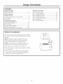
PRODUCT CLEARANCES
The vent hood and liner assemblg must be installed
50" minimum and 36" maximum above the cooking
surface.
NOTE: Installation height should be measured
from the cooking surface to the bottom edge
of the metal hood liner or cabinet surface.
NOTE: UL requires ang combustible surface to be
a minimum of 50" above the cooking surface.
• This hood must be vented to the outdoors.
• This hood mag be mounted
over an island.
onto a wall or installed
• This hood can be installed over ang Monogram
electric!gas cooktop or Monogram Professional
cooktop or range of equivalent
width.
Step
Step
Step
Step
Step
Step
Step
Step
Instructions
1, Install Hood Liner ............................................................
16
2, Connect Electrical ............................................................
17
3, Install Insert Sleeve ........................................................
!8
4, Install Damper Plate ......................................................
19
5, Install Blower Motor ........................................................
20
6, Connect Wiring Harness ..............................................
20
7, Install Filters ......................................................................
21
8, Finalize Installation ........................................................
21
Design Information
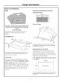
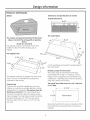
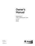
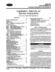
PRODUCT DIMENSIONS
ZVC30
Dimensions
and Specifications
(in inches)
Outside Dimensions
27-1/2_
The Insert Sleeve
The custom canopg must be sized to fit the insert
sleeve. Construct the canopg with an opening
that is:
26"W x 13-3116"D
The opening must be constructed of 3/4" thick
material to allow the sleeve locking clips to
engage.
1/2"
The Supplied Liner
251:,
28-1/2"
1/2"
'2"
21-1/4"
The bottom edge of the insert sleeve has a 7/8"
wide flange on the sides and a 1/2" wide flange
on the front and back.
Remote Location for the Control
The stainless steel liner is shipped with each hood
insert. This non-combustible
liner protects the
underside of the canopg,
The control may be removed from the hood
and installed into a wall or countertop, A 30-ft.
length of wire is supplied to accommodate
most
installations. A blanking plate covers the opening
when the controls are removed.
Custom Liner
The overall
If gou are not using the supplied liner, gou mug
construct a custom non-combustible
liner. Use the
2-1/4" deep.
size of the control
is 4-114" wide and
4
3-11/16"
supplied liner as a template. The opening must be
26'MI x 13-3116"D. 3/4" thick material must
surround the opening to allow the sleeve locking
clips to engage. The insert sleeve inside the cabinet
should be positioned 1/2" from the rear wall so
that the center of the 8" duct is 5-1/2" from the
rear wall.
1-11116"
Control cutout
We recommend that the cutout in granite or other
hard surfaces be made before the countertop is
installed.
Design Information
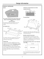
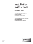
PRODUCT DIMENSIONS
ZVC36
Dimensions
and Specifications
(in inches)
Outside Dimensions
27-1/2"
The Insert Sleeve
The custom canopg must be sized to fit the insert
sleeve. Construct the canopg with an opening
that is:
26"W x 13-3116"D
16-3/4"
The opening must be constructed of 3/4" thick
material to allow the sleeve locking clips to
14"
engage.
1/2"
The Supplied Liner
34-1/2"
1/2"
The bottom edge of the insert sleeve has a 7/8"
wide flange on the sides and a 1/2" wide flange
on the front and back.
Remote Location
The stainless steel liner is shipped with each hood
insert. This non-combustible
liner protects the
underside of the canopg,
The control mag be removed from the hood
and installed into a wall or countertop, A 30-ft.
length of wire is supplied to accommodate
most
installations. A blanking plate covers the opening
when the controls are removed.
Custom Liner
The overall
If gou are not using the supplied liner, gou mag
construct a custom non-combustible
liner. Use the
2-1/4" deep.
supplied liner as a template. The opening must be
26'MI x 13-3/16"D. 3/4" thick material must
surround the opening to allow the sleeve locking
clips to engage. The insert sleeve inside the cabinet
should be positioned 1/2" from the rear wall so
that the center of the 8" duct is 5-1/2" from the
rear wall.
for the Control
size of the control is 4-1/4" wide and
3-11/16"
Control cutout
We recommend that the cutout in granite or other
hard surfaces be made before the countertop is
installed.
Design Information
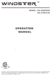
PRODUCT DIMENSIONS
ZVC48
Dimensions
and Specifications
(in inches)
Outside Dimensions
I"
39-1/2"
©
©
©
The Insert Sleeve
The custom canopy must be sized to fit the insert
sleeve. Construct the canopy with an opening
that is:
38-3/4"W x 13-3/16"D
29-1/2"
The opening must be constructed of 3/4" thick
material to allow the sleeve locking clips to
engage.
The Supplied Liner
38-1
46-1/2"
1/2"
21-1/4"
_/
The stainless steel liner is shipped with each hood
insert. This non-combustible
liner protects the
underside of the canopy,
Custom Liner
If you ore not using the supplied liner, you moy
construct a custom non-combustible
liner. Use the
A 1/2" wide flange surrounds
the insert sleeve.
Remote Location
the outside edge of
for the Control
The control may be removed from the hood
and installed into a wall or countertop. A 30-ft.
length of wire is supplied to accommodate
most
installations. A blanking plate covers the opening
when the controls are removed.
The overall
size of the control is 4-1/4" wide and
2-1/4" deep.
3-11/16"
supplied liner as a template. The opening must be
38-3/4"W x 13-3/16"D. 3/4" thick moterial must
surroundthe opening to allowthe sleevelocking
dips to engage. The insertsleeveinsidethe cabinet
should be positioned112"from the rearwallso
thatthe centerofthe 8" duct is5-1/2"from the
reor wall.
Control cutout
1-11116"
We recommend thot the cutout in gronite or other
hard surfaces be made before the countertop is
installed.
Advance Planning
ADVANCE PLANNING
POWER SUPPLY
Ductwork Planning
• This hood is equipped for 8" round ductwork.
• Determine the exact locution of the vent hood,
IMPORTANT - (Please read carefully)
• Plan the route for venting exhaust to the outdoors,
This hood is not designed for a recirculating
venting operation,
• Use the shortest and straightest duct route
possible, For satisfactory performance, duct run
should not exceed 100 ft, equivalent length for any
duct configurations,
• Refer to "Duct Fittings" chart to compute the
maximum permissible length for duct runs to
the outdoors,
• Use rigid metal ductwork only,
• Install u wall or roof cap with damper at the
exterior opening. Order the cap and any transitions
needed in advance.
Wall and Ceiling Framing for Adequate Support
This vent hood is heavy and the cabinet structure
needs to support the weight of the loaded insert
sleeve. Adequate structural support must be
provided in all types of installations.
• Installation will be easier if the vent hood is
installed before the cooktop is installed,
Custom Cabinet Frame Planning
• The custom-built canopy should be sized to
accommodate the hood insert, and ducting
dimensions in the bottom of cabinet should be
26" W bg !3-3/!6"
D for the 30" and 36" models
and 38-3/4" W by !3-3/!6"
D for the 48" models.
Remote Mounting of the Control (Wired}
• The control can be remotely mounted on the wall
or the countertop.
• It is recommended that you use a professional
installer for the countertop cutout.
• It is recommended that the cutout in a granite
countertop or other hard surface be made before
the countertop is installed.
• The cutout needs to be made at least 6 inches
from the edges of the countertop.
• If mounting in the countertop above a drawer,
consideration must be given to the depth of the
control mounting assembly.
• A 30 ft. wire cord is provided. Careful consideration
must be given to the location of the remotely
mounted control.
• It is recommended that the a-wire cord be routed
through !" conduit between the insert sleeve and
the remote mounting location.
WARNING:
FOR PERSONAL SAFETY,THIS APPLIANCE
MUST BE PROPERLYGROUNDED.
AVERTISSEMENT :POUR
DES RAISONS DE SECURITE, CET APPAREIL
DOlT ETRE CORRECTEMENT HIS P, LA TERRE.
Remove house fuse or open circuit breaker before
beginning installation,
Do not use an extension cord or adapter plug with
this appliance, Follow National electrical codes or
prevailing local codes and ordinances.
Electrical Supply
This vent hood must be supplied with 120V, 60Hz,
and connected to an individual, properly grounded
branch circuit, and protected bg a 15 or 20 amp
circuit breaker or time delay fuse.
• Wiring must be 2 wire with ground.
• If the electrical supply does not meet the above
requirements, call a licensed electrician before
proceeding.
• Route house wiring as close to the installation
location as possible, in the ceiling or back wall,
• Connect the hood wiring to the house wiring in
accordance with local codes.
• House wiring must extend to 45" minimum from
bottom of cabinet in order to make connection to
hood wiring.
Grounding Instructions
The grounding conductor must be connected to
a grounded metal, permanent wiring system, or an
equipment-grounding
terminal or lead on the hood.
WARNING:
connection of the equipment-grounding
The improper
conductor can result in a risk of electric
shock. Check with a qualified electrician or service
representative if you are in doubt whether the
appliance is properly grounded.
branchement du fil de
AVERTISSEMENT
:
Le mauvais
raise
la terre peut causer un choc @lectrique.
En cas de doute, consultez un @lectricien qualifi@
ou un technicien pour d6terminer si I'appareil est
la terre,
Advance Planning
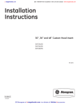
DUCT FITTINGS
Use this chart to compute
maximum permissible lengths for
duct runs to outdoors.
Duct Piece
NOTE: Do not exceed maximum
permissible
equivalent lengths!
Maximum duct length:
100 foot for 8" round duct
(_
Dimensions
Equivalent
Length*
Round,
straight
i ft.
(per foot
length)
3-1/4" x 12"
3-1/4" x 24"
straight
1 ft.
(per foot
length)
90°
elbow
8" round
17 ft.
45°
elbow
8" round
10 ft.
3-:1/4" x 10"
14 ft.
3-1/4" x 12"
90° elbow
15 ft.
3-1/4" x 12"
3-1/4"
x 10"
45° elbow
9 ft.
8 ft.
3-1/4" x 10"
33 ft.
3-1/4" x 12"
90° flat elbow
36 ft.
Quantitg
Used
Flexible ducting:
If flexible metal ducting is used,
all the equivalent feet values in
the table should be doubled.
The flexible metal duct should
be straight and smooth and
extended as much as possible.
DO NOT use flexible plastic
ducting.
NOTE: Any home ventilation
system, such as a ventilation hood,
may interrupt the proper flow of
combustion air and exhaust
required by fireplaces, gas
furnaces, gas water heaters and
other naturally vented sgstems.
To minimize the chance of
interruption of such naturoffg
vented sgstems, follow the
heating equipment manufacturer's
guidelines and safety standards
such as those published by NFPA
and ASHRAE.
8" to 3-1/4" x 10"
2 ft.
_
8"to3-1/4"x12"
or 3-1/4" x 10" transition
2ft.
2 ft.
_
3-1/4" x 10" to 8"
3-1/4" x 12" to 8"
round transition
2 ft.
2 ft.
(_,,_,_
8"
8" to
to 3-1/4"
3-1/4" xx 12"
10"
transition 90° elbow
67 ft.
ft.
3-1/4" x 10" to 8"
5 ft.
_,j_
<_
*Actual length of straight duct plus
duct fitting equivalent. Equivalent
length of duct pieces are based
on actual tests conducted by GE
Evaluation Engineering and reflect
requirements for good venting
performance with any ventilation
hood.
X
3-1/4"
12" to 8"
round transition 90° elbow
S ft.
wall
cap
8" round
with damper
32 ft. with damper
3-1/4" x 12" wall cap
with damper
26 ft. with damper
8" round
roof
cap
44 ft.
3-1/4" x 10" wall cap
w/damper
round roof vent
24 ft.
Total Duct Run.
Total
Equivalent
Length
Installation Preparation
TOOLS AND MATERIALS REQUIRED
_
(NOT SUPPLIED)
1/4" pivoting
soo et
Needle-nose pliers
__
Aluminized
duct tape
"_
_
Knife
L
Wire nuts
S
_
Safety glasses
_;:_
_
Gloves
J
Electric drill and
appropriate bits
3/8" socket/
nut driver
Silicone
Pencil and tape measure
1" conduit (for remote
mounting only)
8" ducting and
caps as needed
1
Step ladder
Plumb line
Phillips and flat blade
screwdrivers
Flashlight
Wire cutter/stripper
Strain relief
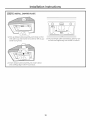
REMOVE THE PACKAGING
CAUTION:
Wear gloves to protect
against sharp edges.
ATTENTION :
Portez des gants pour
_viter les blessures caus_es par les tranchants.
CAUTION:
LIFTTHE INSERT SLEEVE
OUT OF THE BOX BY GRASPING THE SIDES.
J
4. Unscrew the S nuts securing the damper vent
plate assemblg, and remove it from the insert
sleeve. Set the S nuts and the damper vent plate
assemblg aside, as SOUwill be re-installing it later
in the installation process.
ATTENTION : SOULEVEZ
LE
HANCHON
INTERIEUR DE LA BOITE EN SAISISSANT
SES COTES.
1. Open hood carton.
2. Remove the liner, foam and cardboard.
5. Remove the screws attaching the insert sleeve to
the mounting board. Discard the screws.
6. Grasp the insert sleeve bg the outside edges, and
lift straight up and out of the carton.
NOTE: Do not lift the insert sleeve bg the blower
motor,
3. Remove the tape securing the filters to the insert
sleeve, lift the tabs and remove the filters.
7, Remove and properlg discard the plastic wrapping,
8, Remove the parts box and other packaging,
10
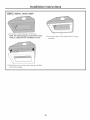
Installation Preparation
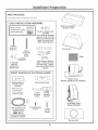
PARTS PROVIDED
Locate the parts packed with the hood.
CHECK INSTALLATION
HARDWARE
Hood liner (packed in
separate carton)
components. Screws
shown
actual size.
Count screws/
screws for
hood liner
5 nuts for damper plate
assembly
(not located in hardware
bag-you must save nuts
when you remove damper
plate from inset hood
while unpacking parts)
Insert sleeve
8 wood
screws for
insert
sleeve
2 wing nuts
with lock
washers for
blower motor
REMOTE MOUNTING
Filters
6 insert sleeve chassis
plugs, 1 (optional) house
wire hole plug, 2 rubber
grommets, 4 insert sleeve
washers
OF THE CONTROL
(WIRED)
Blower motor
(Models ZVC30LSS and ZVC36LSS)
Blanking plate for
remote control
opening*
*NOTE:To be used
on custom hood
when controls are
remotely
mounted.
Control wall bracket
Control
mounting
plate
Control
mounting
bracket
Dual blower motor
(Model ZVC48LSS)
30 ft. of 4-wire cord
(straight-pinned)
with connector
NOTE: Not for
telecommunications
(telephone) network.
2 mounting plate
screws
2 wall
bracket
screws
Damper plate
11
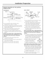
Wall Installation
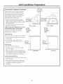
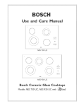
DUCTWORK,
WIRING
Preparation
5-1/2" from
rear wall to
centerline
LOCATIONS
Determine the exact location of the insert
sleeve. Mark the exact centerline location.
The ceiling structure must be capable of
supporting the weight of the insert sleeve
(appro×imatelg 100 pounds) and ang
inadvertent user contact loads,
l
• Measure from the top of the cooking
16"above pencil
surface to the bottom edge of the insert
line indicating
sleeve. Add insert sleeve installation height, bottomof hood
Mark that location.
Use a level to draw a straight horizontal
pencil line on the wall.
4" liner height
NOTE: House duct should drop to 11-1/2"
30" Min.
above bottom edge of insert sleeve.
36" Max,
Location of house duct is important
installation
because it must align with vent of
height
damper plate assemblg.
Ceiling ducting:
If ductwork will vent straight up to the ceiling:
Use a level to draw a centerline straight up
to the ceiling.
On the ceiling, measure 5-1/2" from
the back wall to the centerline of an
8-!/2" hole.
36" from
floor to
36" from
floor to
countertop
countertop
Wall Ducting:
If ductwork will vent to the rear:
® Use a level to draw a centerline straight
up to the ceiling.
I
I
Measure at least 16" above the pencil line
that indicates the bottom installation height,
to the centerline of an 8-1/2" die. duct hole.
(Hole meg be elongated for duct elbow.)
Side view
HOUSE WIRING LOCATION:
The junction box is located inside the top left
side of the hood.
Wiring should enter the back wall at least
15" above the bottom of the insert sleeve,
and within 6" of the left side of the
centerline.
12
I
Front view
Island Installation
Preparation
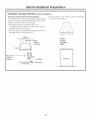
CONSTRUCT CEILING SUPPORT (for Island Installation)
Plan the Location of the Hood and Ductwork
The ceiling structure must be capable of supporting the
weight of the insert sleeve (approximatelu !00 pounds)
and anu inadvertent user contact loads.
The insert sleeve in the ceiling must be centered left
to right over the cooktop,
• Use a plumb bob to check the location, The
countertop/cooktop
below the insert sleeve must be
centered with the insert sleeve.
The insert sleeve should extend beuond the front and
rear edge of the cooking appliance,
Ceiling
30"'Min.
36" Max.
installation
ducting
centerline
height
Hood
Front
I
t
30" Min,
36" Max.
installation
Align with
center of
i
i
cooktop
,
i
height
_-_
j
Side view
Cooktop
Countertop
I
13
I
Installation
Preparation
REMOTE MOUNTING OF THE CONTROL
(WIRED}
REMOTE LOCATION
installed in a backsplash
-- ILWARNING: Disconnect
electrical
d_brancher
I'alimentation
or countertop.
• A cover plate is provided to cover the opening in
the hood when the control is removed.
power from unit before beginning remote control
installation. Failure to do so could result in personal
injurg or damage to the electrical controls.
AVERTISSEMENT
FOR CONTROL
The control can be removed from the hood and
• A 30-ft. length of 4-wire cord is supplied to
accommodate most installations. Because onlg
30-ft. of cord is provided, careful consideration
must be given to the location of the remotelg
mounted control.
: llfaut
61ectrique de I'appareil
avant de commencer I'installation de la commande
distance. II faut suivre cette directive pour @viter
des blessures ou endommager les commandes
61ectriques.
NOTE: Not for telecommunication
network.
(telephone}
• The cord must be routed through the holes in the
insert sleeve, and the rubber grommets put into
place around the cord.
NOTE: On the ZVC30 and ZVC36 models, the cord
needs to be routed through the holes in the insert
sleeve before the damper plate is installed.
• Route the cord through the conduit to reach the
installation location of the control.
3-11/16"
P
1-11116"
14
Control cutout
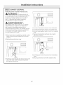
Installation
Preparation
REMOTE MOUNTING
(WIRED) {CONT.)
OF THE CONTROL
WALL MOUNT
COUNTERTOP
Wall
bracket
Control
•
, _"-"r"--..Co nne cto r
4-wire cordi-._"
:
_
Mounting
Screws 4,-_
Mounting bracket _
Control
Jack
plate
Screws, __ord
_-Apply silicone around
_cutout
Mounting
bracket
¼
plate
I. Cut out opening into the woll surface. Cutout
dimensions are 1-11/16" x 3-11/16".
opening
2. Loosen the/4 thumbscrews
control from the insert sleeve. Replace the
control with the blonking plote provided.
I. Cut out opening in the countertop. Cutout
dimensions ore i-ii/16"
x 3-ii/16".
2. Loosen the/4 thumbscrews
ond remove the control
3. Attach the mounting plote to the bock of the
control with the 2 mounting plote screws.
from the insert sleeve. Reploce the control with the
blanking plate provided.
4. Pull the a-wire cord through the opening in
the wall, the woll brocket ond the back of the
mounting brocket.
3. Attoch the mounting plote to the bock of the
control with the 2 mounting plote screws.
NOTE: Use provided cable or cable designated bg
the National Electrical Code, NFPA/ANSI 70, or local
codes. Not for telecommunication
(telephone}
network.
4. Pull the a-wire cord through the opening in the
countertop, ond through the bock of the mounting
brocket.
NOTES: Use provided cable or cable designated bg
the National Electrical Code, NFPA/ANSI 70, or local
codes. Not for telecommunication
(telephone}
network.
S. Connect the mounting brocket to the woll bracket
using the two wall brocket screws. Onlg start the
first 1-2 threads of the screws into the woll, os
gou wont to leove o gop between the two
brockets to occount for the woll thickness.
5. Connect the 4-wire cord to the jack of the
connector on the control.
6. Press the control firmlg into the mounting
so that the clips engoge.
ond remove the
6. Raise the tabs on the mounting
brocket so the brocket will fit
through the woll opening.
brocket
7. Applg silicone oround the cutout opening.
7. Angle the mounting ond woll
brackets ond slide them through
8. Insert the control into the cutout opening.
Tabs
,F_-------"_
the woll cutout.
NOTE: Attach a string to the brackets, so gou can
retrieve them from behind the wall if dropped.
8. Flotten tobs on mounting bracket so theg ore
flush with the wall surfoce, ond tighten the woll
brocket screws to pull the woll brocket flonges
flush with the bockside surfoce of the woll.
9. Connect the a-wire cord to thejock
connector on the control.
of the
I0. Press the control firmlg into the mounting
brocket so thot the clips engoge.
15
Installation
Instructions
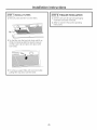
[STEP I] INSTALL HOOD LINER
1. Frame the cutout opening to fit the linen
NOTE: The opening support must be 3/4" thick
wood to accept the liner installation screws.
3. Secure the liner to the cabinet with 6 screws
provided.
2. Slide the liner up Qnd into the opening until flush
with bottom edges.
16
Installation
Instructions
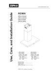
[STEP 2] CONNECT ELECTRICAL
Verifg that power is turned
WARNING:
off at the source.
,fhouse wiring is not
00000
2-wirewith a ground wire,an electrician
willneed
to convertexisting
wiringto meet these specs.
When house wiringisaluminum, be sureto
use U.L approved anti-oxidant
compound
and aluminum-to-copper connectors.
\
AVERTISSEMENT :
Si le cablage de la maison n'est pas un cablage
5 deux ills avec un fil de terre, un @lectricien
doit convertir votre cablage existant 5 ces
caract@istiques techniques. Si le cablage de votre
maison est en aluminium, assurez-vous d'utiliser
un compos@ anti-oxgdant approuv6 et des
raccords aluminium _ cuivre.
4. Connect white leads to branch circuit white lead.
5. Connect blackleadsto branch circuit blacklead.
I. Place insert sleeve on padded, get stable, surface
below cutout (can use flattened carton to pad
surface).
2. Remove the junction
6. Connect green/yellow
lead.
leads to branch circuit green
7. Secure all connections
electrical connector
with wire nuts on each
box cover
00000
\
00000
\
Cove r
Screws
8. Carefully push wires intojunction
cover
Wires
9. Secure junction
3. Pull house wires through wall of insert sleeve and
attach the strain relief. Thread the house wire
through the junction box.
17
box and replace
box cover with original screws.
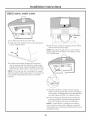
Installation
Instructions
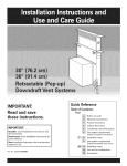
ISTEP 31 INSTALL INSERT SLEEVE
ape
1. Tuck the house wiring out of the wag.
2, Install the insert sleeve into the cutout opening of
custom cabinet frame.
4. Align 8" duct to exhaust opening of insert sleeve
and seal with aluminum tape.
÷
NOTE: House duct should drop to 11-1/2" above
bottom edge of insert sleeve or the bottom of the
3/4" cabinet base.
3. Push the insert sleeve straight up through the
cutout opening until the temporarg locking clips
engage. The locking clips are designed to hold the
insert sleeve in place until it is secured with screws.
NOTE: The locking clips are not designed to support
all of the weight of the insert sleeve. Do not leave the
insert sleeve unattended until screws have been
inserted.
5. Tape the 4 washers in place over the outside
of the 4 front and back holes of the insert sleeve.
The washers are designed to be located between
the insert sleeve and the 3/4" cabinet surface.
6. Press the sleeve up firmlg and secure with the
8 screws provided. The insert sleeve should be
flush with the liner and have no visible gaps.
NOTE: It is IHPORTANT to install front mounting
screw. The front screw hole is difficult to see and
mag require gou to place gour head into the cutout
opening to locate.
18
Installation
Instructions
[STEP 4] INSTALL DAMPER PLATE
1. Pick up damper plate assemblg and rotate so that
vent side is up and bracket is located on left as gou
stand facing hood.
°
3. Secure damper plate assemblg bg placing nuts
on bolts and tightening with socket or wrench.
2. Insert damper plate assemblg into insert sleeve
and carefullg align with 8" house duct.
19
Installation
ISTEP
sl INSTALL
Instructions
BLOWER MOTOR
iioooooii
1. Pick up blower motor and rotate so tabs align
with damper plate bracket.
2. Insert blower motor into insert sleeve through
cutout opening of custom cabinet frame.
3. Place blower motor on damper plate assemblg
bg sliding blower motor tabs into slots of damper
plate assemblg.
00000
4. While holding blower motor in place, lift right side
so that blower motor bolt holes align with bolts
protruding from damper plate assemblg and
secure with lock washers and wing nuts (hand
tighten).
ISTEP 6 1CONNECTWIRING HARNESS
NOTE:On ZVC48,there are three routing clips and two wiring harnessesto connect.
Wiring
harness
Brackets
o ooo o
®
1. Locate both ends of wiring harness.
2. Connect wiring harness bg inserting male into
female opening.
3. CarefullL route wiring harness and ground wire
through two clips attached to blower plate
assemblg.
2O
Installation
Instructions
ISTEP
7] INSTALL
FILTERS
[STEP 8] FINALIZE
INSTALLATION
1.Check to be sure all tape and packaging
materials have been removed.
1. Remove protective film from the filters.
2. Refer to Owner's
instructions.
Clip
2. Tip the filter into the back tab slots and lift up.
While maintaining slight backward pressure
on filter, open clip and press into place with
two hands.
3. To remove, support filter with one hand while
pulling filter clip down with the othen
21
Manual for operating
Notes
22
Notes
23
Note: While performing installations described in this book,
safety glasses or goggles should be worn.
For Monogram ® local service in your area, call
1.800.444.1845.
Note: Product improvement is a continuing endeavor at
General Electric. Therefore, materials, appearance and
specifications are subject to change without notice.
Monogram:
GEConsumer&hldustrial
GEAppliances
GeneralElectricCompany
Louisville,KY40225
ge com
Printed
in Italg
@2006GECompany