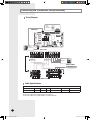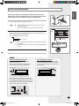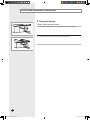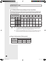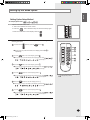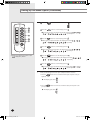
1
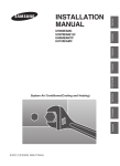
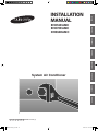
ENGLISH RUSSIAN EΛΛHNIKA System Air Conditioner DEUTSCH PORTUGUÊS ITALIANO FRANÇAIS EH052EAMC EH070EAMC DH094EAMC ESPAÑOL INSTALLATION MANUAL E S F I P D G R DB98-27157A(1) DB98-27157A(1)_E.indd 37 2007-1-23 10:36:06 Safety Precautions The following safety precautions must be taken when using your air conditioner. WARNING INSTALLING THE UNIT • Risk of electric shock Can cause injury or death. • Disconnect all remote electric power supplies before servicing, installing or cleaning. • This must be done by the manufacturer or its service agent or a similarqualified person in order to avoid a hazard. The unit should not be installed by the user. Ask the dealer or authorized- company to install the units except room air conditioners for the U.S.A and Canada area. If the unit is installed improperly, water leakage, electric shock or fire may result. Mount with the lowest moving parts at least 2.5 m above the floor or grade level. (If applicable) The manufacturer does not assume responsibility for accidents or injury- caused by an incorrectly installed air conditioner. If you are unsure aboutinstallation, contact an installation specialist. When installing the built-in type air conditioner, keep all electrical cablessuch as the power cable and the connection cord in pipe, ducts, cablechannels e.t.c to protect them against liquids, outside impacts and so on. This appliance is not accessible to the general public. This applianceshould be installed according to the provided installation instruction. POWER SUPPLY LINE,FUSE OR CIRCUIT BREAKER If the power cord of this air conditioner is damaged, it must be replaced bythe manufacturer, its service agent or similarly qualified persons in order toavoid a hazard. The unit must be plugged into an independent circuit if applicable or con- nect the power cable to the auxiliary circuit breaker. An all pole disconnection from the power supply must be incorporated in the fixedwiring with a contact opening of >3mm. Do not use an extension cord with this product. If the unit is equipped with a power supply cord and a plug, the plug must- be accessible after installation. The air conditioner must be installed in accordance with national wiring regulations and safety regulations wherever applicable. E-2 DB98-27157A(1)_E.indd 2 2007-1-23 13:06:29 ENGLISH ESPAÑOL Contents RUSSIAN EΛΛHNIKA ITALIANO 4 5 9 10 11 13 15 16 17 18 19 20 21 24 25 27 29 33 ITALIANO Preparation for Installation............................................................................ Deciding on Where to Install the Air Conditioner ....................................... Indoor Unit Installation ................................................................................ Purging the Unit .......................................................................................... Connecting the Connection Cord ................................................................ Drain Hose Installation ................................................................................ Connecting the Indoor Unit Assembly Piping .............................................. Cutting/Flaring the Pipes ............................................................................. Checking Correct Grounding ....................................................................... Performing Leak Tests ................................................................................ Insulation ..................................................................................................... Adjusting Air Flow ....................................................................................... Setting Up the Mode Option ........................................................................ Assigning Address to Indoor Unit ................................................................ Additional Functions .................................................................................... Drain Pump Installation (Optional) ............................................................... Troubleshooting .......................................................................................... Parts List ................................................................................................... PORTUGUÊS DEUTSCH E-3 DB98-27157A(1)_E.indd 3 2007-1-23 13:06:29 Preparation for Installation When deciding on the location of the air conditioner with the owner, the following restrictions must be taken into account. General Do NOT install the air conditioner in a location where it will come into contact with the following elements: Combustible gases Saline air Machine oil Sulphide gas Special environmental conditions If you must install the unit in such conditions, first consult your dealer. Accessories The following accessories are supplied with the indoor unit. The type and quantity may differ depending on the specifications. Insulation Cover Pipe in(1) Owner’sInstructions(1) Installation Manual(1) Insulation Drain (1) Insulation CoverDrain(1) Insulation Pipe in(1) Insulation Pipe out(1) Cable-Tie(8) Flexible hose(1) Clamp hose(2) Rubber(8) Insulation Cover Pipe out(1) Wired Remote Controller Accessories Wired remote controller Cable-Tie Cable Clamp M4 x 16 Tapped Screws Indoor unit power drawing cable Communication cable ofthe wired remote controller Wire joint Owner’s Instruction Installation Manual E-4 DB98-27157A(1)_E.indd 4 2007-1-23 13:06:31 ESPAÑOL ENGLISH Deciding on Where to Install the Air Conditioner Indoor Unit There must be no obstacles near the air inlet and outlet. Install the indoor unit on a ceiling that can support its weight. Maintain sufficient clearance around the indoor unit. Make sure that the water dripping from the drain hose runs away correctlyand safely. The indoor unit must be installed in this way, that they are out of publicaccess. (Not touchable by the users) After connecting a chamber, insulate the connection part between the indoorunit and the chamber with t10 or thicker insulation. Otherwise, there can beair leak or dew from the connection part. ITALIANO ITALIANO Space Requirements for Indoor Unit 15 re mo 00 mm or 15 00 mo re m 0m or mm or PORTUGUÊS 15 or mo re DEUTSCH 00 mm re mo RUSSIAN 5mm EΛΛHNIKA 0 15 E-5 DB98-27157A(1)_E.indd 5 2007-1-23 13:06:32 Deciding on where to install the Air Conditioner (Continued) Drawing of the indoor unit EH052EAMC Unit : mm 938.4 (Suspension position) (Service place) 28 28 600 477 (Suspension position) 1000 or more 8 100=800 860 (Air outlet duct flange) (Air outlet duct flange) 900 Inspection hole 22-ø3.2 Discharge side Number 1 2 3 4 5 6 7 8 Description Name Liquid pipe connection RGas pipe connection Drain pipe connection Drain pipe connection Power supply connection Air discharge flange Air filter Hook Suction side Ø6,35 Flare Ø12,7 Flare OD32 ID26 Using drain pump (Optional) For M8~M10 E-6 DB98-27157A(1)_E.indd 6 2007-1-23 13:06:33 ENGLISH ESPAÑOL EH070EAMC (Suspension position) ITALIANO ITALIANO Unit : mm PORTUGUÊS (Service place) (Suspension position) or more Discharge side 1 2 3 4 5 6 7 8 Description Name Liquid pipe connection RGas pipe connection Drain pipe connection Drain pipe connection Power supply connection Air discharge flange Air filter Hook Suction side Ø9,52 Flare Ø15,88 Flare OD32 ID26 Using drain pump (Optional) RUSSIAN Number EΛΛHNIKA (Air outlet duct flange) DEUTSCH Inspection hole (Air outlet duct flanger) For M8~M10 E-7 DB98-27157A(1)_E.indd 7 2007-1-23 13:09:01 Deciding on where to install the Air Conditioner (Continued) DH094EAMC Unit : mm 18-Ø3.2 1188 (Suspension position) 1150 904 (Air outlet duct flanger) 6X135=810 397 (Suspension position) 220 (Service place) 1000 or more 90 Inspection hole 67 117 (Air outlet duct flanger) 90 260 185 480 ODØ32 Discharge side Number 1 2 3 4 5 6 7 8 76 132 144 Suction side Description Name Liquid pipe connection RGas pipe connection Drain pipe connection Drain pipe connection Power supply connection Air discharge flange Air filter Hook Ø9,52 Flare Ø15,88 Flare OD32 ID26 Using drain pump (Optional) For M8~M10 E-8 DB98-27157A(1)_E.indd 8 2007-1-23 13:06:35 ENGLISH Indoor Unit Installation 2 3 Refer to page 6~8 for the dimension. Insert bolt anchors. Use existing ceiling supports or construct a suitablesupport as shown in figure. Install the suspension bolts depending on the ceiling type. Concrete Insert Hole in anchor Hole in plug Suspension bolt(M8)-field supply IMPORTANT Ensure that the ceiling is strong enough to support the weight of the indoor unit.Before hanging the unit, test the strength of eachattached suspension bolt. Support du plafond Screw eight nuts to the suspension bolts making space for hanging the indoor unit. PORTUGUÊS 4 DEUTSCH IMPORTANT You must install the suspension bolts more than 4 when installing the indoor unit. Hang the indoor unit to the suspension bolts between two nuts. Tubing must be laid and connected inside the ceiling when suspending the unit. If the ceiling is already constructed, lay the tubing into position for connection to the unit before placing the unit inside the ceiling. 6 Screw the nuts to suspend the unit. 7 Adjust level of the unit by using measurement plate for all 4 sides. Note For proper drainage of condensate, give a 10mm slant to the left or right side of the unit which will be connected with the drainhose, as shown in the figure. Make a tilt when you wish to install the drain pump, too. EΛΛHNIKA Note RUSSIAN 5 ITALIANO Note ESPAÑOL Mark the place to insert the suspension bolt where you want to install theindoor unit. ITALIANO 1 10mm Drain hose connection port E-9 DB98-27157A(1)_E.indd 9 2007-1-23 13:06:36 Purging the Unit On delivery, the indoor unit is loaded with an inert nitrogen gas. All this gas must therefore be purged before connecting the assemblypiping. To purge the inert gas, proceed as follows. Unscrew the caps at the end of each pipe. Result:All inert gas escapes from the indoor unit. Note To prevent dirt or foreign objects from getting into the pipes during installation, do NOTremove the caps completely unti lyou are ready to connect the piping. E-10 DB98-27157A(1)_E.indd 10 2007-1-23 13:06:37 ENGLISH Connecting the Connection Cord 2 Route the connection cord through the side of the indoor unit and connectthe cable to terminals as shown in page 12. 3 Route the other end of the cable to the outdoor unit through the ceiling &the hole on the wall. 4 Reassemble the electrical component box cover, carefully tightening thescrew. PORTUGUÊS When connecting the cables, you must pass them through the cable clamp to fix them securely. Connect the Connection Cord as seen in next picture , and the torque of screw is 40~70kgf•cm . RUSSIAN EΛΛHNIKA DEUTSCH Note ITALIANO Remove the screw on the electrical component box and remove the cover plate. ITALIANO 1 ESPAÑOL The indoor unit is powered from the outdoor unit via the connection cord. E-11 DB98-27157A(1)_E.indd 11 2007-1-23 13:06:37 Connecting the Connection Cord(Continued) Wiring Diagram Receiver & Display Unit(Optional) MAIN PCB Float SwitchDrain Pump(Optional) Indoor Unit 1(L) 2(N) Vc Vc Vw Vw F1 F2 V1 V2 F3 F4 Wired Remote Controller Communication Power MAIN POWER 1ø, 220- 240V~, 50Hz F1 F2 Outdoor Unit Cable Specifications Single Phase Power supply Max/Min(V) MCCB ELB Power cable length Earth cable 220-240V~/50Hz 264/198 Trip:25A 25A 2.5mm,2wires 10m or less Ø1.6mm,1wire The power cables are not supplied with the air conditioner. The power cables use the grade H07RN-F or H05RN-F materials. E-12 DB98-27157A(1)_E.indd 12 2007-1-23 13:06:38 ENGLISH Drain Hose Installation Care must be taken when installing the drain hose for the indoor unitto ensure that any condensate water is correctly drained outside. Thedrain hose can be installed to the right of the base pan. 2 Cable Clamp Fix the flexible hose to the indoor unit with the supplied cableclamp securely. (Use the screwdriver to fix the flexible hose securely.) Install the drain hose so that its length can be as short as possible.Internal diameter of the drain hose should be the same or slightly biggerthan the external diameter of the drain hose port. Inner diameter of the drain hose Indoor Unit Insulation drain hose Insulation cover drain 32mm(Inner diameter) Note Cable-Tie ITALIANO Note ESPAÑOL Insert the flexible hose to the drain hose port. Give a slightly slant to the drain hose for proper drainage of condensate. Fix the flexible hose to the PVC with the supplied cable tiesecurely. ITALIANO 1 CAUTION Must fit tightly againstbody without any gap. No gap Wrap the drain hose with the insulation drain as shown in figure and secure it. PORTUGUÊS 3 When not installing the drain pump When installing the drain pump Do not give the hose and upward gradient after the connection port. This will cause water to flow backwards when the unit is stopped, resulting in water leaks. If it is necessary to increase the height of the drain hose somewhat, the portion directly after 75cm. If it is raised higher than 75cm, there can be water leaks. DEUTSCH CAUTION 75cm or less EΛΛHNIKA Upward gradien Ceiling Ceiling RUSSIAN Do not apply force to the piping on the unit side when connecting the drain hose. The hose should not be allowed to hang loose from its connection to the unit. Fasten the hose to a wall, frame or other support as close to the unit as possible. Support pieces Ceiling E-13 DB98-27157A(1)_E.indd 13 2007-1-23 13:06:40 Drain Hose Installation (Continued) Testing the drainage Prepare a little water about 5 liters. 1 Pour water into the base pan in the indoor unit as shown in figure. 2 Confirm that the water flows out through the drain hose. E-14 DB98-27157A(1)_E.indd 14 2007-1-23 13:06:41 ENGLISH Connecting the Indoor Unit Assembly Piping There are two refrigerant pipes of differing diameters: ◆ The thickness of tube should not less than 1.0mm A ◆ The inside of copper tube must be clean & has no dust. The connection procedure for the refrigerant pipes varies according to the exit position of the pipes from the indoor unit, as seen when facing the indoor in the “A” side. ◆ Liquid refrigerant port Gas refrigerant port ◆ Drain hose connection port Note 3 Drain hose Liquid refriger- connection port ant port ◆ Torque (kgf•cm) 140~170 kgf•cm 250~280kgf•cm 380~420kgf•cm 440~480kgf•cm 990~1210kgf•cm 990~1210kgf•cm ITALIANO Remove the pinch pipe on the pipes and connect the assembly pipes to each pipe, tightening the nuts, first manually and then with a torque wrench, a spanner applying the following torque. Outer Diameter 6.35 mm (1/4") 9.52 mm (3/8") 12.70 mm (1/2") 15.88 mm (5/8") 19.05 mm (3/4") 22.23 mm (7/8") 2 Gas refrigerant port a. When the indoor unit is above the outdoor unit Indoor unit If the pipes must be shortened refer to page 16. Must use insulator which is thick enough to cover the refrigerant tube to protect the condensate water on the outside of pipe falling onto the floor and the efficiency of the unit will be better. Outdoor unit Oil trap (Must be installevery 10m) DEUTSCH 1 ◆ ESPAÑOL A larger one for the gas refrigerant ITALIANO A smaller one for the liquid refrigerant ◆ PORTUGUÊS ◆ Cut off any excess foam insulation. Be sure that there must be no crack or wave on the bended area. Outdoor unit 5 6 It would be necessary to double the insulation thickness (10mm or more) to prevent condensation even on the insulator when if the installed area is warm and humid. Shape an oil trap as shown in figure the oil trap must be formed every level difference of 10m. Oil trap(Must be installedevery 10m) Indoor unit RUSSIAN 4 EΛΛHNIKA b. When the outdoor unit is above the indoor unit Radius 5cm Oil trap(suction tube) E-15 DB98-27157A(1)_E.indd 15 2007-1-23 13:06:42 Cutting/Flaring the Pipes Connect the pipe within 50m and cutting pieces will not be gone into the pipe as being clean to pipe section. 1 Make sure that you have the required tools available (pipe cutter, reamer, flaring tool and pipe holder). 2 If you wish to shorten the pipes, cut it with a pipe cutter, taking care to ensure that the cut edge remains at a 90° angle with the side of the pipe. Refer to the illustrations below for examples of edges cut correctly and incorrectly. 90 O Oblique Rough Burr 3 To prevent any gas from leaking out, remove all burrs at the cut edge of the pipe, using a reamer. 4 Slide a flare nut on to the pipe and modify the flare. Outer Diameter (D) 6.35 mm (1/4") 9.52 mm (3/8") 12.70 mm (1/2") 15.88 mm (5/8") 19.05 mm (3/4") 22.23 mm (7/8") 5 Check that the flaring is correct, referring to the illustrations below for examples of incorrect flaring. Inclined 6 Depth (A) 1.3mm 1.8mm 2.0mm 2.2mm 2.2mm 2.2mm Damaged Surface Cracked Uneven Thickness Align the pipes and tighten the flare nuts first manually and then with a torque wrench, applying the following torque. Outer Diameter 6.35 mm (1/4") 9.52 mm (3/8") 12.70 mm (1/2") 15.88 mm (5/8") 19.05 mm (3/4") 22.23 mm (7/8") Torque (kgf•cm) 140~170 kgf•cm 250~280kgf•cm 380~420kgf•cm 440~480kgf•cm 990~1210kgf•cm 990~1210kgf•cm CAUTION ◆ In case of welding the pipe, you must weld with nitrogen gas blowing. E-16 DB98-27157A(1)_E.indd 16 2007-1-23 13:06:44 If the power distribution circuit does not have an earth or the ground does not comply with specifications, an grounding electrode must be installed. The corresponding accessories are NOT supplied with the air conditioner. The grounding wire for the telephone line cannot be used to ground the air conditioner. 3 Finish wrapping insulating tape around the rest of the pipes leading to the outdoor unit. 4 Install a green/yellow coloured grounding wire (Ø1.6 mm, section 2-mm2 or greater): ◆ If the grounding wire is too short, connect an extension lead, in a mechanical way and wrapping it with insulating tape (do not bury theconnection) ◆ Secure the grounding wire in position with staples Note ◆ Steel core PVC-insulated green/yellow wire, 2mm2x 3.5 m Terminal M4 To grounding screw 50cm Carefully check the installation, by measuring the grounding resistance with a ground resistance tester. If the resistance is above required level, drive the electrode deeper into the ground or increase the number of grounding electrodes. 6 Connect the grounding wire to the electrical component box inside of the outdoor unit. RUSSIAN 5 DEUTSCH If the grounding electrode is installed in an area of heavy traffic, its wire must be connected securely. EΛΛHNIKA ◆ Note Carbon plastic ITALIANO Determine a suitable location for the grounding electrode: ◆ In damp hard soil rather than loose sandy or gravel soil that has a higher grounding resistance ◆ Away from underground structures or facilities, such as gas pipes, water pipes, telephone lines and underground cables ◆ At least two metres away from a lightening conductor grounding electrode and its cable ITALIANO 2 PORTUGUÊS Select an grounding electrode that complies with the specifications given in the illustration. 30cm 1 ESPAÑOL ENGLISH Checking Correct Grounding E-17 DB98-27157A(1)_E.indd 17 2007-1-23 13:06:45 Performing Leak Tests Leak Test Before completing the installation (insulation of the hose and pipe), you must check that there are no gas leaks. 1 After closing both high and low stop valve of the outdoor unit, inject nitrogen gas into refrigerant pipe. 2 By using soap bubbles, check leak on flare nut connection of pipes. 3 Purge nitrogen gas after finishing leak test. E-18 DB98-27157A(1)_E.indd 18 2007-1-23 13:06:45 ENGLISH Insulation ESPAÑOL Once you have checked that there are no leaks in the system, you can insulate the piping and hose. No gap To avoid condensation problems, place heat-resistant polyethylene foam separately around each refrigerant pipe. Note ◆ Always make the seam of pipes face upwards. Heat resistant polyethylene foam 2 Wind insulating tape around the pipes. 3 Finish wrapping insulating tape around the rest of the pipes leading to the outdoor unit. ITALIANO 1 Insulation cover pipe Insulation pipe ITALIANO Body Be sure to overlap the insulation RUSSIAN EΛΛHNIKA DEUTSCH PORTUGUÊS CAUTION Must fit tightly against body without any gap. E-19 DB98-27157A(1)_E.indd 19 2007-1-23 13:06:46 Adjusting Air Flow E. S. P(External Static Pressure) Setting for Phase Control Motor With its phase control motor, you can adjust the indoor unit fan speed depending on the installation condition. If the external static pressure is high so that the duct becomes longer or if the external static pressure is low so that the duct becomes shorter, adjust the fan speed by referring the following table. Refer to the page 21 to set the option code. Static Pressure(mmAq) Model Step EH052EAMC Mid Hi Low Hi EH070EAMC Mid Low Hi DH094EAMC Mid Low Note 0 1 CMM (CFM) 15 13 11 20 18 16 25 22 19 2 3 4 6 8 - - - - Option Code for Indoor Unit 0114B3 0114B4 0114B4 0114B4 0114B4 -1901CF -190221 -1902F3 -1902F6 -1902FC 011443 011443 011444 011444 011444 -1C019E -1C01FF -1C0271 -1C02F5 -1C02FB 015431 - -1E03F6 015433 -1E0137 - 015433 015433 015434 -1E01AA -1E03BE -1E02F6 ◆ represents E. S. P(External Static Pressure) range of factory setting. You don't have to adjust the fan speed separately if the external static pressure of the installation place is in . When it is out of , input the appropriate option code. ◆ If you input the inappropriate option code, error may occur or the air conditioner is out of order. The option code must be inputted correctly by the installation specialist or service agent. Range of static pressure (Factory preset) Model External static pressure(mmAq) Min. Normal Max. EH052/070EAMC 0 2 4 DH094EAMC 4 6 8 E-20 DB98-27157A(1)_E.indd 20 2007-1-23 13:06:46 ENGLISH Setting Up the Mode Option Setting Option Setup Method For example) Option Code : Prepare of the Option Setup mode. ESPAÑOL 1 a. Take out the batteries of remote control. button simultaneously and insert the battery again. c. Make sure the remote control display shows as Enter the Option Setup mode and select your option according to the following procedure. 1 The default value is . Otherwise, push the button to . ITALIANO 2 . ITALIANO b. Press the 1 2 ◆ Every time you press the button, the display panel reads or 3 repeatedly. 4 button to set the display panel to . ◆ Every time you press the button, the display panel reads ... 3 Press the PORTUGUÊS 2 Press the 5 repeatedly. 6 button to set the display panel to . ◆ Every time you press the button, the display panel reads button to set the display panel to . ◆ Every time you press the button, the display panel reads ... 5 Press the repeatedly. Setting is not required if you want to input . is displayed by default. EΛΛHNIKA 4 Press the repeatedly. DEUTSCH ... button to set the display panel to . ◆ Every time you press the button, the display panel reads ... button to set the display panel to . RUSSIAN 6 Press the repeatedly. ◆ Every time you press the button, the display panel reads ... repeatedly. E-21 DB98-27157A(1)_E.indd 21 2007-1-23 13:06:49 Setting Up the Mode Option (Continued) 7 Press the button, then the default value is . 7 8 8 Press the 9 button to set the display panel to . ◆ Every time you press the button, the display panel reads ... repeatedly. 10 9 Press the 11 button to set the display panel to . ◆ Every time you press the button, the display panel reads 12 ... 10 Press the repeatedly. button to set the display panel to . ◆ Every time you press the button, the display panel reads ... 11 Press the Setting is not required if you want to input . is displayed by default. repeatedly. button to set the display panel to . ◆ Every time you press the button, the display panel reads ... 12 Press the repeatedly. button to set the display panel to . ◆ Every time you press the button, the display panel reads ... 3 repeatedly. Check you made right selections upon completion of the selection. a. Press the inputted. button once to check the former part of option code you ◆ The display part shows b. Press the you inputted. . button once more to check the latter part of option code ◆ The display part shows . E-22 DB98-27157A(1)_E.indd 22 2007-1-23 13:06:52 ENGLISH Press the button. ESPAÑOL 4 ◆ When you press the button towards the indoor unit, the sound 'Ding' or 'Diriring' is heard and the power indicator of the display flashes at the same time. Then the option code setting is completed. (If the sound is not heard, press the button again.) Check the air conditioner operates normally. ITALIANO 5 a. Remove the battery from the remote control. b. Insert the battery into the remote control again. c. Press the ◆ If all indicators of the indoor unit are flashing, plug out the power plug and plug it in again. Then press the button. ITALIANO Note towards the indoor unit. DEUTSCH PORTUGUÊS ◆ If the air conditioner does not operate normally or all lamps indicators flash, check that the correct option code is set up. Option items Remote Control SEG1 SEG2 SEG3 SEG4 SEG5 SEG6 SEG7 SEG8 SEG9 SEG10 SEG11 SEG12 0 1 1 4 B 4 1 9 0 2 F 3 EH070EAMC 0 1 1 4 4 4 1 C 0 2 7 1 DH094EAMC 0 1 5 4 3 3 1 E 0 3 B E RUSSIAN EH052EAMC EΛΛHNIKA Model E-23 DB98-27157A(1)_E.indd 23 2007-1-23 13:06:53 Assigning Address to Indoor Unit 1 Before installing the indoor unit, assign an address to the indoor unitaccording to the air conditioning system plan.. 2 The address of the indoor unit is assigned by adjusting MAIN(SW02) andRMC(SW04) rotary switches. SW02 SW05 SW02 SW04 SW06 SW07 SW04 K1 K2 K3 K4 K5 K6 K7 K8 K9 K10 K11 K12 SW05 SW06 SW07 3 It is required to set the RMC address if you install the wired remote controllerand/or the centralized controller. 4 If you install optional accessories such as the wired remote controller, centralizedcontroller, etc. see an appropriate installation manual. 5 If an optional accessory is not installed, you do not have to set the RMCaddress. However, adjust K1 and K2 switches of the SW05 DIPswitch to “ON”position in this case. E-24 DB98-27157A(1)_E.indd 24 2007-1-23 13:06:54 ENGLISH Additional Functions ◆ Reduces the difference between an actual room temperature and a sensed temperature by the air conditioner when heating. Switch ON Switch OFF K5 2°C compensation 5°C compensation SW06 ITALIANO Switch No. K5 K6 K7 K8 ESPAÑOL Compensation for lost temperature in heating operation Adjusting filter cleaning cycle Switch ON Switch OFF K6 1000 hours 2000 hours K5 K6 K7 K8 SW06 PORTUGUÊS Switch No. ITALIANO ◆ You can adjust the cycle for filter sign indicator. Hot water heater Switch No. Switch ON Switch OFF K7 No use of hot water heater Use of hot water heater DEUTSCH ◆ You must adjust the K7 when you install the hot water heater. K5 K6 K7 K8 RUSSIAN EΛΛHNIKA SW06 E-25 DB98-27157A(1)_E.indd 25 2007-1-23 13:07:00 Additional Functions (Continued) External Control ◆ You must adjust the K11 when you use external control. K 9 K10 K11 K12 SW07 Switch No. Switch ON Switch OFF K11 No use of external control Use of external control ◆ You can use external control when the K11 switch is turned off. Operation ON/OFF Function Connector No. SHORT OPEN CN83(RED) Operation ON Operation OFF ON/OFF Switch CN83(RED) Operation State Display Connector No. Function PIN #1 and #2 of CN81(RED) +12V Out if any error occurs PIN #3 and #4 of CN81(RED) +12V Out when the compressor is operating Error Display AC 220V Comp. Status Display Sub. PCB CN81(RED) E-26 DB98-27157A(1)_E.indd 26 2007-1-23 13:07:02 Drain Pump Installation (Optional) M4 X 12 TappedScrew (4) Cable-Tie (3) Insulation Drain (2) Drain Hose (1) ESPAÑOL Drain Pump and FloatSwitch(1) ENGLISH Accessories Remove the air filter. 2 Assemble the drain socket as seen in the picture after removing the rubbercap. Drain socket Assemble the float switch with the drain pump. Drain pump andfloat switch 4 Connect the drain hose. Drain hose Attach the drain hose tightly with the cable tie or a bondingagent so that it does not get removed or water does not drain. RUSSIAN Note EΛΛHNIKA DEUTSCH 3 PORTUGUÊS ITALIANO ITALIANO 1 E-27 DB98-27157A(1)_E.indd 27 2007-1-23 13:07:03 Drain Pump Installation (optional) (Continued) 5 IInsert the flexible hose into the drain socket until it clicks. Note Must fit tightly against body without any gap. ◆ Check if water does not drain. ◆ Insulate the drain hose so that frost does not form. Cable-tie Indoor unit Drain hose drain Insulation 6 Float switch Connect the cable to the electrical component box as shown at the figure. Note ◆ Connect the drain pump cable to yellow terminal(CN74)and the float switch to black terminal(CN51). Drain pump 7 Adjust K4 DIPswitch(SW05) to the “OFF” position. Switch No. SW05 K4 Note Switch Position Using Drain Pump ON X OFF O ◆ Wrap the drain tube outlet on the right and left side ofthe indoor unit with an insulating materials. E-28 DB98-27157A(1)_E.indd 28 2007-1-23 13:07:04 ENGLISH Setting up Option Detection of errors If an error occurs during the operation, one or more LED flickers and the operation is stopped except the LED. If you re-operate the air conditioner, it operates normally at first, then detect an error again. ESPAÑOL ◆ ◆ LED Display on the receiver & display unit LED Display Indicators Abnormal conditions Blue ITALIANO Concealed Type Remarks Red X X X X Error of heat exchanger sensorin the indoor unit X X X Error of the outdoor temperature sensor Error of the condensor temperature sensorError of the discharge temperature sensor X X X X EΛΛHNIKA 1. Indoor unit error (Display is unrelated with operation) 1. No communication for 2 minutesbetween indoor units (Communication error for more than 2 minutes) 2. Outdoor unit error (Display is unrelated with operation) 2. Indoor unit receiving the communicationerror from outdoor unit X X X RUSSIAN 3. Outdoor unit tracking 3 minutes error PORTUGUÊS X Error of temperature sensor in the indoor unitt (Open/Short) X DEUTSCH X Power reset ITALIANO Standard Type 4. When sending the communication errorfrom the outdoor unit, the mismatchingof the communication numbers andinstalled numbers after completion oftracking (Communication error for more than 2 minutes) ● On Flickering X Off ◆ If you turn off the air conditioner when the LED is flickering, the LED is also turned off. E-29 DB98-27157A(1)_E.indd 29 2007-1-23 13:07:05 Setting up Option (Continued) LED Display Indicators Concealed Type Abnormal conditions Blue Remarks Red Standard Type X Communication error between indoor units X X 1. Error of electronic expansion valve close 2. Error of electronic expansion valve open 3. 2’nd detection of high temperature cond 4. 2’nd detection of high temperaturedis- X X Detection of the float switch X X Error of setting option switches for optionalaccessories X X charge 5. Error of reverse phase6. Compressor down due to 6’th detectionof freezing EEPROM error X X X EEPROM option error ● On ◆ Flickering X Off If you turn off the air conditioner when the LED is flickering, the LED is also turned off. E-30 DB98-27157A(1)_E.indd 30 2007-1-23 13:07:06 ENGLISH Wired remote controller Explanation Compressor down due to protection control of the dischargetemperature sensor Remark Error about protection control of the outdoor unit ITALIANO Display ESPAÑOL ◆ If an error occurs, is displayed on the wired remote controller. If you would like to see an error code, press the Test button. Control due to the condenser temperature sensor when coolingmode ITALIANO Error of the low pressure switch (Protection control) Reverse phase error (Protection control) In removing frost Error of condensor temperature sensor (Open/Short) Error about the outdoor unitsensor (Open/Short)Detection during the operation of the indoor unit(sensing and sending errorsinto the communication data) PORTUGUÊS Error of the outdoor temperature sensor (Open/Short) Error of discharge temperature sensor (Open/Short) DEUTSCH -System down caused by communication error after comple- Communication and theindoor unit errors tionof tracking- Mismatching of the indoor unit numbers set with those communication after completion of 5 times tracking Self-diagnosis of theindoor and Error of temperature sensor in the indoor unit (Open/Short) outdoor unit Error of the heat exchanger sensor in the indoor unit (Open/ Short) EΛΛHNIKA Error of electronic expansion valve open in the outdoor unit(when it is detected more than once) Error of electronic expansion valve close in the outdoor unit(when it is detected more than once) RUSSIAN Error of communication between the indoor unit and the wire- Wired remote controllererrors dremote controller Master wired remote controller�Slave wired remote controller COM1/COM2 Cross-installed error Error of setting option for wired remote controller COM2 E-31 DB98-27157A(1)_E.indd 31 2007-1-23 13:07:08 Troubleshooting (Continued) Outdoor unit ◆ If an error occurs during the operation, it is displayed on the outdoor unit PCB. Display Explanation High temperature of Discharge (Protection control) Remark Error about protectioncontrol of outdoor unit High temperature of outdoor heat exchanger (Protection control) Low pressure of outdoor (Protection control) COMP DOWN to protect being frozen Instant power supply failure (Power on/ off) In removing frost Errors about outdoor unitsensor (OPEN/SHORT)Detection Error of temperature sensor in outdoor heat exchanger (OPEN/ during the operation of indoor unit(Sensing and sending SHORT) errorsinto the communication data) Error of Discharge TEMPsensor (OPEN/SHORT) Error of OUTTEMPsensor (OPEN/SHORT) System Down caused by communication error aftercompletion Communication and indoorunit errors of tracking Mismatching of the indoor unit numbers set with thosecommunicated after completion of tracking Self-diagnosis of indoorand Error of float switch in indoor unit outdoor unit (x:indoorunit address) Error of setting option switches for optional accessories x OPEN/SHORTerror of room sensor in indoor unit x OPEN/SHORTerror of eva in sensor in indoor unit x Erreur du démarrage du ventilateur Flicker (Below -5°C when cooling (Outdoor temperature) Flicker Over 30°C when heating (Outdoor temperature) Displays of operating status K1, K2, K3, K4, K5 Flicker The order of priority : E1 E2 E5 P0 P1 P3 P5 P9 P6 t1 t2 t3 tu t0 E3 qx rx vx K1, K2, K3, K4, K5 - In case that the same error displays from multi-indoor units, the one having the fast eraddress has the priority. E-32 DB98-27157A(1)_E.indd 32 2007-1-23 13:07:11 ENGLISH Parts List Receiver & Display Unit Accessories Concealed Type ◆ Receiver & display unit Receiver & display unit 4 2 Owner’s instructions Installation manual Wire kit 1 1 1 ITALIANO 1 STS 2S-2x10 2S-4x12 tapped screw tapped screw Wire kit ESPAÑOL ◆ Standard Type ◆ Receiver & display unit Wire kit M4x16 tapped screw Cable-tie Cable clamp Owner’s instructions Installation manual Wire kit 1 7 2 5 1 1 1 Owner’s instructions Installation manual 1 1 PORTUGUÊS Wireless remote controller ITALIANO ◆ Battery 1 2 Remote control STS 2S-2x10 holder tapped screw 1 2 RUSSIAN EΛΛHNIKA Wireless remote controller DEUTSCH Wireless Remote Controller Accessories E-33 DB98-27157A(1)_E.indd 33 2007-1-23 13:07:12 Parts list (Continued) Centralized Controller Accessories Centralized controller Cable-tie Cable clamp M4x16 tapped screw Owner’s instructions Installation manual 1 2 5 7 1 1 Function Controller Accessories Function controller Cable-tie Cable clamp M4x16 tapped screw Owner’s instructions Installation manual 1 2 6 7 1 1 Transmitter Accessories Transmitter Transmitter power cable Transmitter communication cable Installation manual 1 1 1 1 ◆ Note If you would like to install the centralized controller, you must install the transmitter in the outdoor unit. 7-day Scheduler Accessories 7-day Scheduler Cable-tie Cable clamp M4x16 tapped screw Owner’s instructions Installation manual 1 2 2 4 1 1 E-34 DB98-27157A(1)_E.indd 34 2007-1-23 13:07:14 RUSSIAN EΛΛHNIKA DEUTSCH PORTUGUÊS ITALIANO ITALIANO ESPAÑOL ENGLISH Memo E-35 DB98-27157A(1)_E.indd 35 2007-1-23 13:07:15 DB98-27157A(1)_E.indd 36 2007-1-23 13:07:15