1
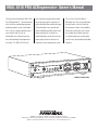
MAX 5510 PRO ACRegenerator
Owner’s Manual
™
®
POWER
MAX® 5510 PRO
MODEL M5510-PRO
1690 Corporate Circle, Petaluma CA 94954 • www.panamax.com
ACRegenerator
™
™
MAX 5510 PRO ACRegenerator Owner’s Manual
®
Thank you for purchasing this MAX® 5510
been specifically engineered to enhance
This is truly a Firewall for Noise™!
Pro, ACRegenerator™! You now own one
the performance and life expectancy of
With power this clean, your audio/video
of the finest line conditioning and power
high-end Audio/Video entertainment gear.
or home theater system will finally be
protection products on the market today.
The combination of our sophisticated
able to perform up to its full capabilities.
Over 25 years of power protection experi-
power conditioning and the world’s finest
Performance alone makes this a world-
ence and more than 10 years of
power protection has resulted in an
class product but we didn’t stop there;
Audio/Video noise filtration experience
Audio/Video power center that meets the
its styling complements and completes
were utilized during the development of
power quality needs for each piece of
even the most sophisticated Audio/Video
this model. The MAX® 5510 Pro has
equipment in your entertainment system.
showcase.
POWER
MAX® 5510 PRO
ACRegenerator
™
MODEL # M5510-PRO
PANAMAX, the Panamax logo and MAX are registered US trademarks of Panamax.
ACRegenerator, Firewall for Noise, SurgeGate Plus, Protect or Disconnect and SignalPerfect are trademarks of PANAMAX.
SIDACtor is a registered US trademark of Teccor Electronics, Inc. TiVo is a trademark of TiVo, Inc.
TABLE OF CONTENTS
Before You Begin.........................................................1
Convenience Lamp................................................7
Introduction.................................................................2
Voltage Sense Triggers..........................................7
Connection Diagram....................................................3
Isolation Transformer Circuit Breaker.....................8
Feature Overview.........................................................4
Coaxial Line Protection..........................................8
Feature Details
Telephone Line Protection......................................8
Analog Voltmeter & Ammeter.................................5
AC Surge Protection..............................................8
Convenience Outlet................................................5
SurgeGate Plus™ Protection..................................9
Diagnostic Lights...................................................5
Automatic Over & Under Voltage Protection..........9
Sequential Startup/Shutdown................................6
Technical Specifications...............................................9
High-Current Outlet Bank......................................6
RS-232 Command Specification................................10
Isolated Switched Outlet Bank................................6
Isolated vs. Balanced Power.......................................11
Filtered Outlet Banks 1 and 2..................................7
Troubleshooting.........................................................12
AV Signal Lline Protection......................................7
BEFORE YOU BEGIN
In addition to this owner’s manual, items included with the MAX® 5510-PRO package are:
1 - MAX®5510-PRO
POWER
MAX® 5510 PRO
ACRegenerator
™
2 - Rack ears w/ screws for
rack mounting option
1 - RJ-11 Telephone Cable
1 - LED Convenience Lamp
1 - CAT 5 Ethernet Cable
3 - Coax Cables for
Satellite TV, Cable TV
and/or Antennas
1 - IEC 320, 120V/15A
detachable power cord
Please verify that you have received all these items. If not, contact Panamax.
USA & Canada (800) 472-5555 • (707) 283-5900 • Fax (707) 283-5901
1
INTRODUCTION
Your Audio/Video components are constantly
being bombarded by electromagnetic interference
(EMI) and radio frequency interference (RFI)
through their power cords. This contaminated
power can affect analog and digital equipment and
will degrade the overall performance of your entire
system. Digital components can also introduce
noise on their AC power lines, which can interfere
with the performance of analog components.
Common symptoms of contaminated power
include pops, hisses, hums, visual artifacts, etc.
Most power filtering devices will remove some of
this interference but don’t provide a comprehensive solution to the problem.
The MAX® 5510 Pro’s Power Filtration System is
the Complete Solution!
Level 1 - for Digital Source Components or
Display Devices:
True isolation from contaminated power sources is
the first level. The heart of the MAX® 5510 Pro is
a 720VA, Isolation Transformer that provides
power to four outlets for your digital source components or displays. AC Regeneration through
electromagnetic coupling between the primary and
secondary windings of the transformer allows only
clean, pure AC power to reach your equipment.
None of the EMI/RFI contamination gets past the
isolation transformer! In addition, any noise generated by your digital source components is isolated and prevented from reaching the rest of your
equipment through their power cords.
Two different power modes, Isolated and
Balanced, are available as output from the isolation
transformer. These are selected with the front
panel AC Regeneration pushbutton. In the Isolated
mode, the secondary (load side) of the transformer’s winding is completely isolated from
ground connections. Digital source components
(with 2-blade power plugs) that are plugged into
these outlets are also isolated, eliminating ground
loops and hum.
In the Balanced mode, a center tap wire from the
secondary winding is connected to ground. This
creates a balanced voltage waveform (+60V LineGround & -60V Neutral-Ground, 180 degrees out
of phase), which still provides 120VAC to your
2
equipment but has the benefit of canceling any
common mode noise between Line/Neutral and
Ground.
The MAX® 5510 Pro allows you to switch between
Isolated and Balanced modes since there is no way
to categorically state that “Isolated Power” is better than “Balanced Power” or that “Balanced
Power” is better than “Isolated Power”. Both
modes provide clean, regenerated power to your
digital source components. One setting may provide better results than the other for your particular system but the only way to really know is to try
both and use the one that sounds better to you.
Results will depend upon the quality of your
incoming power, noise sources close to your home
or system, your combination of components and
the quality and routing of interconnected cabling.
Due to this, different results may be observed
when comparing picture and sound quality from
identical equipment in different physical locations.
Level 2 – for Analog Components:
The second level in the Power Filtration system
features two banks of independently filtered outlets (2 outlets per bank) for your analog components. These outlet banks utilize “Balanced Double
L” filter circuits which are far superior to any other
design in filtering out all forms of electromagnetic
and radio frequency interference in both common
and normal modes. Cross-contamination between
your components is also eliminated with this
design.
Level 3 – for High-Current Components:
The third level of the system specifically addresses the unique power requirements of current hungry components such as amplifiers and powered
subwoofers. These components rapidly draw
large amounts of current to replenish their capacitors after thunderous bass notes. Line conditioners that utilize coils (inductors) in series with the
AC power line can “choke” off this large in-rush
current, thereby reducing the amplifiers’ ability to
operate at peak performance levels, resulting in a
flat, dead sound. The MAX® 5510 Pro’s high-current outlets are fed by noise filtration circuitry that
does not utilize coils and provides full, unimpeded
power for your amplifiers and powered subwoofers.
Other Convenience Features Enhance the
Functionality:
Although the MAX® 5510 Pro’s functionality
revolves around noise filtration and power protection, many other exciting features enhance your
overall entertainment experience, including:
• An analog, backlit voltmeter indicates the AC line
voltage coming into your system.
• An analog, backlit ammeter shows the actual
current draw of all your connected components,
giving a visual reference as to how your system is
functioning under a variety of conditions.
• A front panel pushbutton controls the meter
lighting intensity (High, Low, Off) and color (Blue
or Amber).
• A detachable rear panel LED convenience lamp
simplifies system setup in low-light situations.
• An Always-On, convenience outlet on the front
panel is for temporary AC connections.
As you read through the rest of this manual, you’ll
discover many more unique features. As home
theater enthusiasts, we care about the quality of
your listening and/or viewing experience. Our
goals are to:
• Make power better (conditioning that allows your
system to perform up to its full capabilities)
• Make power safer (protect your investment from
damaging power disturbances)
• Enhance the pleasure you get from your A/V system
Thank you for choosing Panamax for your power
quality needs. Please finish reading the instructions, install the MAX® 5510 Pro and enjoy the full
potential of your entertainment system.
1690 Corporate Circle, Petaluma CA 94954 • www.panamax.com
CONNECTION DIAGRAM
STEP 1
Typical AC Power, RS232 and 12V Trigger Connections
DVD
AMPLIFIER
HOME AUTOMATION
CONTROL
CD PLAYER
AUDIO VIDEO RECEIVER
CIRCUIT
BREAKER
USB
LED
LIGHT
IN
R
ALWAYS ON OUTLETS
ISOLATED OUTLETS
AC INLET
TRIGGER
DELAY
12V TRIGGER
IN
OUT
TRIGGER
ENABLE
RS-232 Control
IN
G
IN
B
ISOLATED
OUTLETS DELAY
HIGH CURRENT
OUTLETS
HIGH CURRENT
OUTLETS DELAY
GROUND
LUG
PROPERLY
GROUNDED
AC OUTLET
LINE LEVEL AUDIO / VIDEO
OUT OUT OUT OUT OUT
CIRCUIT
BREAKER
IN
H
IN
V
LAN / TELCO
LINE
TV
SATELLITE 1
SATELLITE 2
CATV / ANT
EQUIP
SUBWOOFER
VCR
SATELLITE RECEIVER
PVR (TiVo)
STEP 2 Basic Signal Line Connections
DUAL LNB
SATELLITE DISH
VIDEO PROJECTOR*
*Remote components
powered from
different AC circuits
LINE LEVEL AUDIO / VIDEO
OUT OUT OUT OUT OUT
CIRCUIT
BREAKER
USB
LED
LIGHT
12V TRIGGER
IN
OUT
IN
B
IN
H
OUT
IN
V
IN
LAN / TELCO
LINE
EQUIP
OUT
CATV / ANT
IN
DVD
OUT
VIDEO
AC INLET
IN
G
SWITCHED
OUTLETS DELAY
RS-232 Control
TRIGGER
DELAY
ISOLATED OUTLETS
IN
SATELLITE 2
IN
R
ALWAYS ON OUTLETS
HIGH CURRENT
OUTLETS DELAY
HIGH CURRENT
OUTLETS
TRIGGER
ENABLE
PHONE
JACK
CATV
AUDIO
AUDIO VIDEO RECEIVER
AUDIO
PVR (TiVo)
VIDEO
GROUND
LUG
SATELLITE 1
VIDEO
CIRCUIT
BREAKER
TV
SATELLITE RECEIVER
AUDIO
AUDIO
USA & Canada (800) 472-5555 • (707) 283-5900 • Fax (707) 283-5901
3
FEATURE OVERVIEW
1. Power Switch and LED: 2. Meter Lights Switch:
Pushbutton; activates a turnon or shutdown sequence for
the Isolated and High-Current
outlets. The Green LED will
be illuminated when the unit is
plugged into an AC outlet and
the power switch is in the
“ON” position. The LED flashes during the outlet turn-on
and turn-off delay periods.
Pushbutton; controls
brightness of the Ammeter
and Voltmeter backlighting.
Cycles among five settings;
High Blue, Low Blue, High
Amber, Low Amber, OFF
3. LED Indicators:
4. AC Regeneration
Control and LED
Indicators:
Switched Outlets, Voltage
Trigger, Unsafe Voltage,
Isolated Power and
Balanced Power status
indicators.
Select either Isolated
Power Mode and
Balanced Power Mode
for your digital source
components or video
display device
5. Ammeter:
Backlit analog meter
measures current
draw for connected
equipment.
6. Voltmeter:
7: Convenience Outlet:
Backlit analog meter
measures incoming
voltage source from
0-150 VAC.
Provides a quick convenient
way to plug in components
such as camcorders and video
game systems.
POWER
MAX® 5510 PRO ACRenerator™
1. 15A Main Circuit
Breaker: Opens in the
2. High Current Outlet
Bank: Two delayed outlets
3. Isolated (Switched)
Outlets: Four outlets provide
4. Filtered Outlet Banks
1& 2: Four, Always-On,
5. Isolated Outlets
Circuit Breaker:
event that equipment
plugged into the MAX
5500 draws too much
current. When white is
visible, the breaker has
opened. Reduce the
load and push to reset.
designed for high current
components such as
amplifiers and powered
subwoofers. The current
available to connected
equipment is not limited
by the noise filtration
components.
complete isolation for digital
source components such as
DVD players or display devices
like plasma TVs or DLP
projectors. These outlets are
completely isolated from the
rest of the system.
Balanced Double L filtered
outlets for low current analog audio components such
as pre-amplifiers, receivers,
VCR's and tape decks. Two
outlets per filter bank.
Opens in the event that
equipment connected
to the Isolation
Transformer Outlets
exceeds 6 amps current draw. When white
is visible, the breaker
has opened. Reduce
the load and push to
reset.
MAIN BREAKER
ALWAYS ON OUTLETS
ISOLATED OUTLETS
HIGH CURRENT OUTLETS
6. RS232
Control
Interface: DB-9
male connector.
Use to connect the
M5510-Pro to a
home automation
system.
7. Lamp
Receptacle:
8. Line Level
Audio/Video Jacks: Color-
USB jack. The
convenience
lamp included
with the
M5510-Pro is
to illuminate
the rear panels
of other components during
setup.
coded RCA jacks, female, 5
pair. Use to protect the main
system from backdoor surges
coming in on the signal lines.
9. Satellite Coax Jacks:
Two pairs of F-Connectors
optimized for Satellite TV
signal line protection.
ISOLATED OUTLETS BREAKER
SATELLITE 1
LINE LEVEL AUDIO / VIDEO
OUT
OUT
RS232 CONTROL
OUT
OUT
OUT
USB
LED
LIGHT
IN
OUT
SATELLITE 2
GROUND
IN
G
IN
R
12V TRIGGER
IN
OUT
IN
B
IN
H
TRIGGER
ENABLE
TRIGGER
DELAY-ON
HC
OUTLETS
DELAY
Detachable power cord
connects to this receptacle.
11. Ground Lug: Provides
a common grounding point
for equipment with separate
ground leads
12. DC Trigger Input:
3.5mm (1/8”) Mini-Plug
jack. Connect to a
remote trigger device that
uses a DC voltage signal
to initiate a startup/shutdown sequence.
3.5mm (1/8”) Mini-Plug jack.
The M5510-Pro can generate its
own 12VDC trigger to control
another device.
14. Trigger
Enable Switch:
16. Trigger Delay
Switch: Sets the
Enables or disables
the DC Trigger
input function.
delay time (0 or 10
seconds) between
receiving a DC trigger
input signal and when
the M5510-Pro sends
its DC Trigger output
signal.
15. High-Current Outlet Delay Switch:
OUT
CATV
IN
13. DC Trigger Output:
4
IN
SWITCHED
OUTLETS
DELAY
IEC 320 C13 120V/15A
10. IEC Main
Power Receptacle:
IN
V
LAN / TELCO
17. Isolated
Outlets Delay
Switch: 3-position
slide switch. Allows
adjustment of the
Turn-Off delay for
the 4 Isolation
Transformer Outlets.
Choose between
“always-on”, and
10 seconds.
3-position slide switch. Allows adjustment of the
Turn-On delay for the 2 Delayed High Current
Outlets. Choose between 0 and 10 seconds.
1690 Corporate Circle, Petaluma CA 94954 • www.panamax.com
OUT
19. CATV Coax Jacks:
One pair of F-Connectors
optimized for Cable TV,
Antenna or Cable Modem
signal line protection.
18. LAN/Telephone Jacks:
In/Out connections for Ethernet,
telephone line or pay-per-view
line protection.
FEATURE DETAILS
The indicators are:
POWER
Power Switch and LED Indicator: Momentary
Pushbutton (non-locking); activates a turn-on or
shutdown sequence for the Isolated (Switched) and
High-Current outlet banks. The Green LED will be
illuminated when the unit is plugged into an AC
outlet and the power switch is in the “ON” position.
Switched Outlets: Green LED. This light indicates the status of the Isolated (Switched) and HighCurrent outlet banks. When the LED is ON, both outlet banks are on and providing power. When the LED
is OFF, the power to these two outlet banks is also
OFF.
Press and hold the button >2 seconds to turn the
High Current and Isolated outlet banks On/Off.
Voltage Trigger: Green LED. This light indicates
status of the DC voltage trigger.
If the unit is already on and the power button is
pressed quickly (< 2 seconds), the High Current and
Isolated Outlet banks are turned Off, then back On
(sequenced according to the delay settings). This
prevents accidentally turning the connected equipment Off and provides an easy method of cycling
power to reboot components that may lock up.
When enabled by the rear-panel switch and a DC
voltage is sensed by the input trigger circuitry, this
LED turns ON along with the switched outlets. Both
the LED and the outlets will be OFF when the DC
voltage trigger is not receiving a signal.
When disabled by the rear-panel switch, the LED will
remain ON and front-panel power switch will control
the On/Off status of the switched outlets.
Meters: The analog meters are backlit to provide
the ability to view readings in a dark room. LEDs
(light emitting diodes) are used in order to provide
durability and long life.
MAX® 5510 PRO ACRenerator™
MAX® 5510 PRO ACRenerator™
POWER
Unsafe Voltage: Red LED. Under normal voltage
conditions, this light stays off. When this light is
flashing slowly (once every 2 seconds), it indicates
an under-voltage or over-voltage condition. When
the light is flashing quickly (twice per second), it
indicates a 10 second recovery period from an
under/over-voltage condition. This LED will flash
quickly when the MAX 5510-Pro is first plugged in
to the wall outlet.
The Voltmeter samples the incoming voltage from
the wall outlet and provides a visual representation of
the available power. The Voltmeter is Always-On and
indicates the incoming line voltage even during an
unsafe voltage condition. Readings above 150V will
not be accurate due to the meter’s damping characteristics.
AC Regeneration Control: Pushbutton switch
used for selecting the power supply mode for the
digital source components. One of the adjacent
LEDs for Isolated Power and Balanced Power will
illuminate to indicate the active switch position.
The Ammeter measures the amount of current
being drawn by the connected equipment and the
M5510-Pro. The Ammeter needle will fluctuate as
music or movie soundtracks call upon the amplifiers
to reproduce thunderous bass notes. During an
unsafe voltage condition, the Ammeter will continue
measuring the amount of current being drawn by the
Max 5510-Pro, but since all of the connected equipment has been disconnected by the protection circuitry, the needle will be only slightly above zero.
Isolated Power: Green LED. When this light is
ON, it indicates that the Isolated Power Mode has
been selected for the power supply to the
Isolated/Switched Outlets.
Balanced Power: Green LED. When this light is
ON, it indicates that the Balanced Power Mode has
been selected for the power supply to the
Isolated/Switched Outlets.
Meter Lighting: The front panel pushbutton
controls the meter lighting and cycles among five
settings; High Blue, Low Blue, High Amber, Low
Amber, OFF
Diagnostic Indicator Lights: The MAX 5510-Pro
is loaded with special features to save your connected equipment from many different forms of dangerous power disturbances. Diagnostic lights on the
front panel inform you in the event of either a power
disturbance or when a special feature is activated.
MAX® 5510 PRO ACRenerator™
Convenience Outlet: A single outlet on the front
panel of the Max 5510-Pro provides an easy-toreach power source for electronic equipment typically
used on a part time basis. Such equipment includes
anything from video game systems to camcorders.
Do not use this outlet for household appliances like
vacuum cleaners!
The convenience outlet provides clean, protected
power for your sensitive electronic equipment. This
outlet is Always-On and will continually supply a
steady source of power. It is important to remember
that power will be disconnected only in the event of
an unsafe voltage condition.
USA & Canada (800) 472-5555 • (707) 283-5900 • Fax (707) 283-5901
5
FEATURE DETAILS (continued)
Isolated/Switched Outlet Bank:
Sequential Startup/Shutdown:
Complex audio/video systems may be susceptible
to voltage transients generated internally at startup/shutdown if all of the equipment is powered on
or off at the same time. This can cause speaker
“thumps” which are not only annoying but can also
damage the speakers. The MAX 5510-Pro is
designed to eliminate these transients by providing
a “start-up” delay for the High Current outlets and a
“shutdown” delay for the switched Isolation
Transformer Outlets. This allows the components
plugged into the switched outlets to power-up and
stabilize before any amplifiers and powered subwoofers are turned on. This sequence is reversed
during shutdown. The amplifiers and powered subwoofers turn off, their power supplies drain, and then
the equipment plugged into the switched outlets is
turned off.
MAIN BREAKER
ISOLATED OUTLETS
HIGH CURRENT OUTLETS
Four outlets (one bank of four) are fed power through
the heart of the MAX 5510-Pro, the Isolation
Transformer. These outlets should be used for digital
components such as DVD players or display devices
like Plasma TVs or DLP projectors.
GROUND
IEC 320 C13 120V/15A
Pure, clean power is obtained by using the isolation
transformer to regenerate the AC current. The power
from a typical wall outlet is contaminated with electromagnetic (EMI) and radio frequency (RFI) interference (noise) picked up by the power lines between
the power utility’s generating plant and the wall outlet. This contaminated power feeds the isolation
transformer's primary windings and is regenerated
(through electromagnetic induction) as clean power
on the isolated secondary windings. The outlets are
connected to the secondary windings, which have no
physical connection to the primary windings. This is
True Isolation! Not only will it isolate your digital
source equipment from contaminated power, but also
prevent any noise generated in the digital components from flowing back to other connected equipment.
Information on setting the delay times is included in
the Isolated/Switched Outlets and High Current
Outlets sections that follow.
High-Current Outlet Bank:
OUTLETS
ISOLATED OUTLETS BREAKER
LINE LEVEL AUDIO / VIDEO
MAIN BREAKER
GROUND
IEC 320 C13 120V/15A
HIGH CURRENT OUTLETS
ISOLATED OUTLETS
The two high-current outlets allow amplifiers and
powered subwoofers to work to their full potential.
When the movie thunders with a terrific explosion or
when the music reaches a climactic crescendo, an
amplifier has to rapidly draw large amounts of current to replenish its capacitors. Traditional line conditioners impede this current draw, in effect, starving
an amplifier and resulting in a flat, dead sound. The
High-Current Outlet Bank provides clean, filtered
power to amplifiers but has no current limiting
components to impede performance.
The high current outlets are designed with a turn-on
delay option of 0 or 10 seconds. The 2-position,
HC Outlet Delay switch on the back of the MAX
5510-Pro is used to select the desired time delay.
When a delay is selected, the high-current outlets
will turn-on after the Isolated/switched outlets and
turn-off before the Isolated/switched outlets (if they’re
not set to always-on). With a delay, the connected
equipment will not power up simultaneously, thus
preventing loudspeaker noises such as “thumping”.
RS232 CONTROL
OUT
OUT
OUT
OUT
OUT
IN
R
IN
G
IN
B
IN
H
IN
V
USB
LED
LIGHT
I
12V TRIGGER
IN
OUT
I
LAN / TELCO
TRIGGER
ENABLE
TRIGGER
DELAY-ON
HC
OUTLETS
DELAY
SWITCHED
OUTLETS
DELAY
IN
A 2-position slide switch (Switched Outlets
Delay) located on the rear panel controls the timing
for the Isolation Transformer Outlets. Together, these
outlets can be set as “always-on” or with a turn-off
delay of 10 seconds to prevent speaker “thump”.
This switch provides the option of having a total of
eight always-on outlets (4 Filtered Outlets and 4
Isolation Transformer Outlets).
When set to the 10 second delay position, the
Isolation Transformer Outlets will remain as Switched
outlets, controlled by the Power pushbutton and/or
the DC Voltage Sense Trigger. In this situation, the
Isolation Transformer Outlets will not power down
until after the selected time delay has elapsed.
Two different power modes, Isolated and Balanced,
are available as output from the isolation transformer.
These are selected with the front panel AC
Regeneration pushbutton. In the Isolated mode,
the secondary (load side) of the transformer’s winding is completely isolated from ground connections.
Digital source components (with 2-blade power
plugs) that are plugged into these outlets are also
isolated, eliminating ground loops and hum.
In the Balanced mode, a center tap wire from the secondary winding is connected to ground. This creates
a balanced voltage waveform (+60V Line-Ground & 60V Neutral-Ground, 180 degrees out of phase),
which still provides 120VAC to your equipment but
has the benefit of canceling any common mode noise
between Line/Neutral and Ground.
6
USA & Canada (800) 472-5555 • (707) 283-5900 • Fax (707) 283-5901
FEATURE DETAILS (continued)
DC Triggers:
Filtered Outlet Banks 1 & 2:
ALWAYS ON OUTLETS
ISOLATED OUTLETS
NT OUTLETS
ISOLATED OUT
RS232 CON
12V TRIG
IN
Four outlets (two banks / two outlets per bank) are
fed through separate “Balanced, Double L” noise filtration circuits. These circuits are designed to eliminate the AC contamination that is most detrimental to
the performance of analog or video components like
stereo receivers, VCRs or televisions. The two dedicated filters are carefully engineered to provide power
filtration and inter-component "noise isolation" for
both "common-mode" (line/neutral-to-ground) and
"normal-mode" (line-to-neutral) EMI/RFI. This
means that high-frequency interference will be drastically reduced not only from the incoming power but
also from equipment plugged into the other outlet
banks, regardless of what "mode" it occurs in. Even
equipment with ungrounded, 2-blade plugs, receives
clean power.
ISOLATED OUTLETS BREAKER
Input Trigger: This feature provides an ON/OFF
trigger for the MAX 5510-Pro using a DC voltage
control signal. Many components such as preamplifiers and receivers have a 12VDC trigger builtin, and will transmit a constant power signal when
turned on and in use. This power signal will initiate
the startup or shutdown sequence of the MAX 5510Pro’s isolated/switched and high current outlets. An
AC adapter of the appropriate voltage, plugged into a
switched outlet on the receiver, may also be used if a
12V trigger is not built in.
SAT
LINE LEVEL AUDIO / VIDEO
OUT
OUT
OUT
OUT
OUT
IN
R
IN
G
IN
B
IN
H
IN
V
USB
LED
LIGHT
RS232 CONTROL
IN
SAT
12V TRIGGER
IN
OUT
IN
LAN / TELCO
TRIGGER
ENABLE
TRIGGER
DELAY-ON
HC
OUTLETS
DELAY
SWITCHED
OUTLETS
DELAY
IN
The trigger input uses a standard 3.5mm mono miniplug jack. Please note: The front panel pushbutton
must be left in the “ON” position if you are using
the DC Input Trigger and not connected to a Home
Automation system through the RS232 port.
POWER
Each outlet bank is specifically engineered to remain
ON continually to provide a constant power source
for programmable analog or video components. A
digital video recorder and VCR are two examples of
components that require constant power. A digital
video recorder relies on continual power to record
the cable signal and retain its programmed information. A VCR should be connected to one of these
always-on, filtered outlets to maintain correct clock
time and programmed recording information.
Input Trigger Enable Switch: This switch is
used to disable or enable the Input Trigger feature.
The circuitry for the voltage sense trigger also controls the Voltage Trigger Diagnostic LED on the front
panel. When disabled, the front panel Trigger LED
remains lit and the front panel pushbutton controls
the ON/OFF state of the switched and high current
outlets.
When enabled, and a DC voltage is sensed by the
Input Trigger circuitry, the front panel Trigger LED
will light to indicate that the voltage sense circuit is
ON and the MAX 5510-Pro’s switched outlets are ON.
POWER
A/V signal Line Protection:
ISOLATED OUTLETS BREAKER
SATELLITE 1
LINE LEVEL AUDIO / VIDEO
OUT
OUT
OUT
OUT
OUT
IN
R
IN
G
IN
B
IN
H
IN
V
USB
LED
LIGHT
RS232 CONTROL
IN
12V TRIGGER
IN
OUT
TRIGGER
DELAY-ON
HC
OUTLETS
DELAY
OUT
CATV
LAN / TELCO
TRIGGER
ENABLE
OUT
SATELLITE 2
IN
SWITCHED
OUTLETS
DELAY
IN
OUT
In the event of a power surge, system components
plugged into different AC receptacles and/or circuits
can create voltage differentials that result in “groundskew” surges on the signal lines. These “backdoor”
surges can be as damaging to your equipment as an
externally generated surge. Examples of this type of
equipment include ceiling mounted video projectors
or powered subwoofers located away from the main
system components. The MAX® 5510 Pro provides
five line level protection circuits that are optimized
for audio and video signals. The clamping level is
7.5 VDC. Attenuation is less than 1db from 20 Hz to
6 MHz so that optimal performance is achieved and
signal integrity is not compromised. Although the
circuits are individually labeled for R, G, B, H & V
video signals, they may be used for any combination
of audio or video signal lines. The circuitry is
compatible with High Definition component video,
S-Video, composite video or audio signals.
LINE LEVEL AUDIO / VIDEO
OUT
RS232 CONTROL
SATELLITE 1
LINE LEVEL AUDIO / VIDEO
RS232 CONTROL
OUT
OUT
OUT
OUT
OUT
IN
R
IN
G
IN
B
IN
H
IN
V
USB
LED
LIGHT
IN
12V TRIGGER
IN
OUT
TRIGGER
DELAY-ON
HC
OUTLETS
DELAY
OUT
CATV
LAN / TELCO
TRIGGER
ENABLE
OUT
SATELLITE 2
IN
SWITCHED
OUTLETS
DELAY
IN
OUT
The convenience lamp included with your MAX®
5510-Pro plugs into an industry standard USB jack on
the rear panel. Its purpose is to provide better visibility
of other components and their A/V connections during
system setup. Warning: The USB jack only provides
power. The lamp will be ON whenever it is plugged in.
DO NOT use this jack for other USB devices.
OUT
OUT
SAT
IN
R
12V TRIGGER
IN
OUT
IN
G
IN
B
IN
H
IN
V
IN
LAN / TELCO
TRIGGER
ENABLE
TRIGGER
DELAY-ON
HC
OUTLETS
DELAY
SWITCHED
OUTLETS
DELAY
IN
RS232 CONTROL
USB
LED
LIGHT
IN
SAT
IN
R
12V TRIGGER
IN
OUT
IN
G
IN
B
IN
H
IN
V
IN
LAN / TELCO
TRIGGER
ENABLE
TRIGGER
DELAY-ON
HC
OUTLETS
DELAY
SWITCHED
OUTLETS
DELAY
IN
ISOLATED OUTLETS BREAKER
SATE
LINE LEVEL AUDIO / VIDEO
OUT
RS232 CONTROL
OUT
OUT
OUT
OUT
USB
LED
LIGHT
IN
SATE
12V TRIGGER
IN
OUT
ISOLATED OUTLETS BREAKER
OUT
IN
IN
R
Convenience Lamp:
OUT
USB
LED
LIGHT
IN
G
IN
B
IN
H
IN
V
IN
C
LAN / TELCO
TRIGGER
ENABLE
TRIGGER
DELAY-ON
HC
OUTLETS
DELAY
SWITCHED
OUTLETS
DELAY
IN
Output Trigger: The MAX 5510-Pro is capable of
generating its own 12VDC remote signal to control
other components. In its default state, this output
turns ON when the Input Trigger receives a signal
and OFF when the input trigger signal is turned off.
This output also uses a standard 3.5mm mono miniplug jack.
Output Trigger Delay Switch: This switch allows
the selection of 0 or 10 second delay in turning on
the 12VDC output signal. There is no delay when it
turns off.
RS232 Trigger Control: The MAX 5510-Pro’s
command set default is “ATTACHTRIG” (Trigger
Attached), meaning that the ON/OFF state of the
Output Trigger is dependent on the Input Trigger.
When connected to a Home Automation system
through the RS232 port, operation of the Output
Trigger can be divorced from the Input Trigger and
the automation system can control the ON/OFF state
of the Output Trigger. This is accomplished through
the “DETACHTRIG” (Trigger Detached) command.
USA & Canada (800) 472-5555 • (707) 283-5900 • Fax (707) 283-5901
7
FEATURE DETAILS (continued)
Circuit Breakers:
OUT
OUT
OUT
OUT
IN
Telephone/LAN Line Protection:
OUT
SATELLITE 2
MAIN BREAKER
ALWAYS ON OUTLETS
ISOLATED OUTLETS
HIGH CURRENT OUTLETS
GROUND
IEC 320 C13 120V/15A
ALWAYS ON OUTLETS
ISOLATED OUTLETS BREAKER
SATELLITE 1
LINE LEVEL AUDIO / VIDEO
OUT
OUT
OUT
OUT
OUT
USB
LED
LIGHT
RS232 CONTROL
IN
IN
G
IN
R
12V TRIGGER
IN
OUT
IN
B
IN
H
IN
V
IN
TRIGGER
DELAY-ON
HC
OUTLETS
DELAY
OUT
CATV
LAN / TELCO
TRIGGER
ENABLE
OUT
SATELLITE 2
SWITCHED
OUTLETS
DELAY
IN
OUT
There are two separate circuit breakers on the back
panel of the MAX 5510-Pro. The main circuit
breaker will trip only if the total current draw
exceeds the maximum current rating (15A). This
means that collectively, all outlets must draw more
than 15 Amps before the circuit breaker will trip.
IN
G
IN
B
IN
H
IN
V
IN
This unit provides both telephone and LAN protection on one set of RJ-11/45 jacks. The telephone
circuit uses pins 4 & 5 while the LAN circuit uses
pins 1, 2, 3 & 6. Adapters or custom cables (not
included) must be used when utilizing both protection circuits at the same time.
OUT
CATV
LAN / TELCO
SWITCHED
OUTLETS
DELAY
IN
OUT
LAN
There is also a 6 Amp circuit breaker to protect
the 720 VA Isolation Transformer and its circuitry.
The Isolation Transformer provides pure power for
digital source components, which require very little
current to operate at peak performance.
Please note: Do not plug high-powered
amplifiers or powered subwoofers into the
Isolation Transformer Outlets. Their current
requirements may exceed the 6 Amp limit
and cause the circuit breaker to trip.
TEL
1 2 3 4 5 6 7 8
RJ-45
Satellite TV receivers and DVR’s (digital video
recorders) require telephone line connections for
subscription services. The MAX 5510-Pro provides
surge protection for this line. The circuitry utilizes
auto-resetting PTCRs and solid-state SIDACtors“ for
reliability and unsurpassed protection. The clamping
level of the MAX 5510-Pro's telephone protector is
260 volts. This will allow typical ring voltage (90130VAC) and operating battery voltage (-48DC) to
pass through the circuit and still protect the modem
in your satellite receiver or DVR from damage.
Coaxial Line Protection:
SATELLITE 1
VIDEO
All coaxial cable sheaths from outdoors must
be grounded to the building grounding electrode system where they enter the building
(per applicable NEC/CEC code). A driven
ground rod is not adequate.
OUT
OUT
IN
OUT
SATELLITE 2
IN
H
IN
V
IN
OUT
CATV
N / TELCO
IN
IN
G
IN
B
IN
H
IN
V
LAN / TELCO
SWITCHED
OUTLETS
DELAY
LINE
EQUIP.
Panamax's exclusive SignalPerfect™ Technology
provides application specific protection for your
satellite and cable TV equipment. The satellite
connections are for coaxial cables connected to a
DBS (single or dual LNB) satellite dish. The CATV
connection is for a non-amplified rooftop antenna or
cable TV line. Alternatively, it may be used to protect
the equipment plugged into the MAX 5510-Pro from
"backdoor" surges in situations where the video
signal is run to another room for a 2nd television.
OUT
To protect a telephone modem line (DVR or Satellite
TV receiver) or network cable, connect a telephone
cable or network cable from the wall jack outlet to the
LINE jack of the 5510-PRO. Then connect a telephone cable or network cable from the EQUIP. jack
on the UPS to the equipment’s telephone jack or network device.
Please Note: The protection circuitry will not work
if the phone lines are reversed. The incoming phone
cable must be connected to the “LINE” jack and the
cable to the audio/video equipment must be connected to the “EQUIP” jack.
AC Surge Protection:
SATELLITE 1
LINE LEVEL AUDIO / VIDEO
OUT
OUT
OUT
OUT
IN
OUT
SATELLITE 2
IN
G
IN
B
IN
H
IN
V
IN
OUT
CATV
LAN / TELCO
SWITCHED
OUTLETS
DELAY
IN
OUT
SATELLITE 1
LINE LEVEL AUDIO / VIDEO
OUT
OUT
OUT
OUT
IN
OUT
SATELLITE 2
IN
G
IN
B
IN
H
IN
V
IN
OUT
CATV
LAN / TELCO
SWITCHED
OUTLETS
DELAY
IN
8
OUT
Cable TV (Including HDTV) & Cable Modems:
TV tuners operate at approximately 500 millivolts
(1/2 volt) and utilize the frequency spectrum of 50
MHz to 950 MHz. Digital cable boxes and cable
modems typically operate at slightly higher voltages
while cable modems utilize the frequency range
below 50 MHz. The clamping level of the MAX
5510-Pro's CATV protection circuitry is 1400 millivolts (1.4 volts). The circuitry is shielded to prevent
interference and has been optimized to have less than
1dB of signal loss throughout the entire frequency
range up to 950 MHz.
Satellite TV: Satellite dish LNB's can require up to
24 volts to operate and utilize the frequency range of
950 MHz to 2.2 GHz. The clamping level of the MAX
5510-Pro's satellite protection circuitry is 27 volts;
just 3 volts above the maximum operating voltage.
The circuitry is shielded to prevent interference and
has been optimized to have less than 1dB of signal
loss throughout the entire 950 MHz to 2.2 GHz
range.
When the MAX 5510-Pro AC Regenerator is subjected to a high voltage surge, its voltage output is limited to a safe level and the high levels of surge current
are diverted away from the connected equipment.
• When subjected to a 6,000V (open circuit voltage)
/ 500A (short circuit current) surge, the MAX 5510Pro limits its voltage output to less than 330V peak,
UL’s best rating.
• If the magnitude of the surge is greater than the
capacity of the surge protection components, the
MAX 5510-Pro's Protect or Disconnect Circuitry‘ will
disconnect your equipment in order to protect it.
1. Voltage reaches an unsafe level.
2. If surge is greater than MAX® 5510-Pro
capacity, it disconnects.
USA & Canada (800) 472-5555 • (707) 283-5900 • Fax (707) 283-5901
FEATURE DETAILS (continued)
The MAX 5510-Pro requires line voltage to return to
within the safe operating range for 10 seconds before
returning to normal operating mode. This is referred
to as "Over/Under Voltage Recovery". The safe operating range is considered 5V above the under-voltage
threshold and 5V below the over voltage threshold.
Once this safe operating range is reached, the MAX
5510-Pro will perform the following functions:
Patented Over/Under Voltage Protection:
1. Voltage reaches an unsafe high
level and the SurgeGate Plus™
disconnects.
2. Voltage reaches a safe level and
SurgeGate Plus™ automatically
reconnects.
3. Voltage reaches an unsafe low level
and SurgeGate Plus™ disconnects.
4. Voltage reaches a safe level and
SurgeGate Plus™ automatically
reconnects.
The MAX 5510-Pro constantly monitors the AC line
voltage for unsafe voltage conditions such as prolonged over voltages and under voltages (brownouts).
These unsafe conditions pose a very dangerous threat
to all electronic equipment within the home. If the
MAX 5510-Pro senses an unsafe power condition, it
will automatically disconnect your equipment from the
power to protect equipment from damage. Once the
voltage returns to a safe level, the MAX 5510-Pro will
automatically reconnect the power.
POWER
1. Unsafe Voltage LED will flash 4 times per second for Over/Under voltage Recovery.
2. Power is restored to all connected equipment
after the 10-second delay.
If the line voltage exceeds the over voltage threshold
or falls below the under voltage threshold, the MAX
5510-Pro will perform the following tasks until line
voltage returns to a safe level:
1. Disconnects power to all connected equipment.
2. Unsafe Voltage LED is activated and will blink
once per second during the unsafe voltage condition.
POWER
TECHNICAL SPECIFICATIONS
GENERAL
DC TRIGGER OUTPUT
Dimensions................17.25” W x 12” D x 3.5” H, (4.1” H including feet)
Weight.............................................................................................31 lbs.
Connection.......................................................................3.5 mm mono mini-plug
Voltage and Polarity...............................................................12V DC, + Center Pin
Current .......................................................................................................350mA
AC CIRCUIT PROTECTION AND FILTRATION
Initial Clamping Level.....................................................................................200V
UL 1449 Surge Suppression Rating................................................................330V
Protection Modes....................................................................... L - N, L - G, N - G
Line Voltage...............................................................................................120VAC
Max Current Rating.....................................................................15A (1800 Watts)
Response Time...............................................................................................<1ns
Joule Rating........................................................................................2325 Joules
Peak Impulse Current................................................................................91,000A
Catastrophic Surge Circuit ..............................................................................YES
Thermal Fuse...................................................................................................YES
Over/Under Voltage Protection.........................................................................YES
Over-voltage shutoff threshold / Response time........137±4 VAC, 10 milliseconds
Under-voltage shutoff threshold / Response time......95±4 VAC, 500 milliseconds
NOISE FILTRATION:
Filtered Outlet Banks........................................................55 dB (100 KHz - 1 MHz)
Isolation Transformer Outlets
Common Mode........................................................120 dB (100 KHz - 1 MHz)
Normal Mode..............................................................50 dB (100 KHz - 1 MHz)
High-Current Outlets
Normal Mode..............................................................50 dB (100 KHz - 1 MHz)
DC TRIGGER INPUT
Connection.......................................................................3.5 mm mono mini-plug
Voltage and Polarity...........................................3-18VDC nominal, bi-directional
Current Requirement....................................................................................>25mA
SATELLITE CIRCUIT
Clamping Level................................................................................................27V
Attenuation...............................................................<1 dB from 950MHz - 2.2GHz
Shielded...........................................................................................................YES
Connections......................................................................Gold plated, Female “F”
ANT/CATV CIRCUIT
Clamping Level...............................................................................................1.4V
Attenuation.............................................................................<1 dB up to 950MHz
Shielded...........................................................................................................YES
Connections......................................................................Gold plated, Female “F”
TELEPHONE CIRCUIT
Clamping Level..............................................................................................260V
Capacitance......................................................................................30pf (approx.)
Suppression Modes...........................................................Metallic & Longitudinal
Wires Protected....................................................................2 wire/ 1 pr. (pins 4,5)
Fuseless/Auto-Resetting..................................................................................YES
Connections............................................................................................RJ-11/45
LAN CIRCUIT
Compatibility........................................................................10/100 baseT Ethernet
Clamping Level...................................................................................................8V
Wires Protected.............................................................................pins 1, 2, 3 and 6
Connections...................................................................................................RJ-45
Design and specifications subject to change without notice due to product improvement.
USA & Canada (800) 472-5555 • (707) 283-5900 • Fax (707) 283-5901
9
MAX PRO-SERIES RS-232 COMMAND SPECIFICATIONS
1. OVERVIEW
The Panamax Pro-Series product family has a RS232 interface that allows it to communicate with a wide variety of equipment.
The purpose of this document is to outline the command set used to communicate with the Pro-Series (PS) products.
Commands and responses are in the form of ASCII character STRINGS TERMINATED
with ASCII 13, line feed (ASCII 10) or NULL (ASCIØ).
DB9 Pinout Diagram
5 4 3 2 1
6 7 8 9
PIN NO.
1
2
3
4
5
6
7
8
9
2. PORT SETTINGS
Baud Rate:
9600bps
Data Bits:
8
Start Bits:
1
Stop Bits:
1
Flow Control:
None
Null modem cable not required.
SIGNAL
RECEIVE DATA
TRNSMIT DATA
GROUND
-
3. CONTROLLER COMMANDS
The following are commands made by the controller to Pro-Series products.
Command String
Description / Response
2.1
POWERON
Changes the front panel button status to
ON. Initiates a power-on sequence if the
previous state is OFF.
2.2
POWEROFF
Changes the front panel button status to
OFF. Initiates a power-off sequence if the
previous state is ON. (Default)
2.3
CYCLESW
Initiates a power cycle sequence for the
Switched Outlets only.
2.4
CYCLEHC
Initiates a power cycle sequence for the
High Current Outlets only.
2.5
CYCLE
Initiates a power-cycle sequence. Switched
& high-current outlets turn off, followed by
a 10 second delay, followed by a power-on
sequence.
2.6
ALLOFF
Turns off all outlets. Forces front panel
button status to OFF.
2.7
DETACHTRIG
Disconnects 12V trigger output from 12V
trigger input
2.8
ATTACHTRIG
12V trigger input passes through to 12V
trigger output (Default)
2.9
TRIGOUTLO
Forces the 12V trigger output to 0V. Does
not work when trigger is attached to 12V
trigger input.
2.10
TRIGOUTHI
Forces the 12V trigger output to 12V. Does
not work when trigger is attached to 12V
trigger input.
10
Command String
Description / Response
2.13
?TRIGSTAT
Request the status of the 12V trigger input. PS responds with:
a) 12VINHI if voltage is sensed on the12V input
b) 12VINLO if 0V is sensed on the 12V input
c) BUTTONON if the ON/OFF button status is ON.
d) BUTTONOFF if the ON/OFF button status is OFF.
e) 12VOUTHI if the trigger output is ON (+12V)
f) 12VOUTLO if the trigger output is OFF (0V)
2.14
?OUTLETSTAT Request the status of the outlet banks. PS responds with:
a) MAINACON if all outlets (main relay) are ON
b) MAINACOFF if all outlets are OFF
c) SWITCHEDON if the switched outlets are ON
d) SWITCHEDOFF if the switched outlets are OFF
e) HICURRENTON if the high-current (delayed) outlets are ON
f) HICURRENTOFF if the high-current outlets are OFF
2.15
?PWRSTAT
Request the status of the input voltage
a) NORMAL if the voltage is within limits
b) OVERVOLTAGE if the voltage is greater than 132VAC
c) UNDERVOLTAGE if the voltage is less than 95VAC
d) RECOVERY if recovering from an over/undervoltage state but
has not yet restored power to outlets.
2.18
?ID
Request that the unit identify itself. Returns the following:
PANAMAX: MAX 5510-PRO
FW: SFW5510
REV: revision
2.19
HELP
All commands and queries listed above are transmitted.
USA & Canada (800) 472-5555 • (707) 283-5900 • Fax (707) 283-5901
ISOLATED vs. BALANCED POWER
Power Modes in the MAX® 5510
Balanced Power
Single-phase grounded-neutral power
Supply
The standard method of residential power delivery in the U.S.
The neutral, or "grounded" conductor, is bonded to the earth, or
"grounding" conductor. The N-G panel bond creates a severe
imbalance with respect to common-mode currents, which can
lead to "hum" in A/V equipment. There are three problems with
this configuration that are specifically targeted by our "Isolated"
and "Balanced" power modes:
1. Line and neutral current imbalance. Unbalanced currents in
the L-N can radiate magnetic fields, which can couple inductively
from connected power cords to nearby A/V cables.
2. Ground skew. Voltage drops due to common-mode current
flowing into the earth ground can cause a skew between signal
ground references in interconnected A/V equipment.
3. Line and neutral voltage imbalance. Unbalanced voltages
from line and neutral to ground can cause connected power
cords to radiate electrical fields, which can couple capacitively to
nearby A/V cables.
LINE
Equipment
LINE
NEUTRAL
NEUTRAL
GROUND
GROUND
With "Balanced Power", the asymmetric, zero-volt N-G reference
at the panel is replaced by a symmetric ground reference
between line and neutral. Hum-producing common-mode
currents (2) and radiated electrostatic fields in the connected
power cords (3) are both eliminated by voltage phase cancellation. Radiated magnetic fields can still be evident (but to a much
lesser degree than with grounded-neutral power), unless the
impedances from L-G and N-G in the connected equipment are
equal.
Conclusion
Isolated Power
Supply
LINE
Equipment
LINE
NEUTRAL
NEUTRAL
GROUND
GROUND
"Balanced" and "Isolated" Power are both exceedingly efficient
at overcoming the inherent problems of the unbalanced earth
ground reference in domestic single-phase power systems,
with small but definable distinctions. They are both effective in
reducing common mode currents and radiated magnetic and
electrostatic fields from connected power cords. The primary
difference is simple: "Isolated Power" is better at reducing the
magnetic (inductive) component, and "Balanced Power" is better
at reducing the electrical (capacitive) component. Because all
A/V cables have some amount of inductance and capacitance
(defined collectively as "impedance"), they are susceptible to
both types of interference, and the trade-offs will vary with
the system configurations.
With "Isolated Power" the N-G panel bond is broken by floating
the line and neutral, and the ground reference voltage is driven to
neutralize the hum-producing ground leakage currents (2).
Consequently, L-N currents are equalized, effectively eliminating
magnetic field radiation from connected power cords through
current phase cancellation (1). Radiated electrical fields can still
be evident (but to a much lesser degree than with grounded-neutral power), unless the impedances from L-G and N-G in the
connected equipment are equal.
USA & Canada (800) 472-5555 • (707) 283-5900 • Fax (707) 283-5901
11
TROUBLESHOOTING
My power cable does not reach the wall
outlet. Can I use any extension cord to
make it reach?
The 6 Amp, Isolation Transformer circuit
breaker continually trips. What is the
problem?
I connected the LED Convenience Lamp
and the lamp will not work. What is the
problem?
No, Panamax extension cords are the only
extension cords that you can use while keeping
your warranty valid.
The four Isolation Transformer outlets share the
720 VA Isolation transformer for their power
source. The connected equipment plugged into
the four outlets are drawing more than 6 Amps
collectively, causing the circuit breaker to trip.
These four outlets are designed specifically for
low-current, digital source components. Check
to see if you have connected a high current
amplifier or subwoofer to the Isolation
Transformer Outlets. If so, unplug the high current components and plug them into the High
Current Outlet Bank.
Check to see if the MAX 5510-Pro is in an
unsafe voltage condition by looking to see if the
unsafe voltage LED is lit. If the LED is lit, then
wait until voltage is back to normal and the light
will turn back on. If the unsafe voltage LED is
OFF and the light is still not on, call Panamax
Customer Service for help.
The provided coax or telephone jumper
cables are not long enough to reach my
equipment. Can I use other cables?
Yes, any length cable of the same type is fine.
There is an audible buzz/hum coming
from my Max 5510-Pro. What is the
cause of this and how do I make it go
away?
This can be caused by certain appliances; most
commonly lamps with High-Low dimmer switches and some room heaters, which use only half
of the AC sine wave. These appliances distort
the AC wave through a small DC bias placed on
the AC supply. Some custom audio equipmentespecially amplifiers with toroidal power transformers, may react unfavorably to this distortion,
and buzz. The Max 5510-Pro’s isolation transformer will remove this waveform distortion and
protect the loads plugged into the transformerisolated outlets. If the distortion is bad, you may
actually hear the Max 5510-Pro buzzing slightly
as it works to correct the AC power. The best
way to stop the buzz is to find the source of the
disturbance (most likely a quartz lamp) and plug
it into a different branch circuit. Panamax
Technical Support will be glad to help you if you
have any questions about this.
12
The Isolation Transformer Outlets are not
switching ON or OFF with the MAX 5510Pro. How can I fix this?
These outlets may be set as either switched or
always-on outlets. The 2-position, Switched
Outlets Delay switch on the back panel controls
this. Change the setting of this switch from
always-on to a 10 second delay. This will allow
the Isolation Transformer Outlets to become
switched outlets.
The MAX 5510-Pro is ON but the
Voltmeter and Ammeter are not lit up.
What is the problem?
Check the Meter Light Dimmer control to see if
the lighting is turned OFF. The pushbutton
switch cycles between High-Amber, Low-Amber,
High-Blue, Low-Blue and OFF. Call Panamax
Customer Service for help if the switch has no
affect.
USA & Canada (800) 472-5555 • (707) 283-5900 • Fax (707) 283-5901
PANAMAX, the Panamax logo and MAX are registered US trademarks of Panamax. ACRegenerator and SignalPerfect are trademarks of PANAMAX.
SIDACtor is a registered US trademark of Teccor Electronics, Inc. TiVo is a trademark of TiVo, Inc.
USA & Canada (800) 472-5555 • (707) 283-5900 • Fax (707) 283-5901
1690 Corporate Circle, Petaluma, CA 94954
Tel: (707) 283-5900
Fax:: (707) 283-5901
Email: [email protected]
Web: www.panamax.com
© 2004 Panamax
INS0762 Rev A 12/04