1
ESU10012
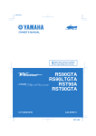
OWNER’S MANUAL
Read this manual carefully
before operating this vehicle.
RS90PB
RS90PLTB
RST90B
RST90PGTB
LIT-12628-03-03
8HV-28199-10
DIC183
U8HV10E0.book Page 1 Monday, May 16, 2011 1:15 PM
ESU10041
Read this manual carefully before operating this vehicle. This manual
should stay with this vehicle if it is sold.
U8HV10E0.book Page 1 Monday, May 16, 2011 1:15 PM
Introduction
ESU10121
Congratulations on your purchase of a
Yamaha snowmobile. This model is the result
of Yamaha’s vast experience in the production of fine sporting and touring snowmobiles.
It represents the high degree of craftsmanship
and reliability that have made Yamaha a leader in these fields.
This manual will give you an understanding of
the operation, inspection, and basic maintenance of this snowmobile. If you have any
questions concerning the operation or maintenance of your snowmobile, please consult a
Yamaha dealer.
Yamaha continually seeks advancements in
product design and quality. Therefore, while
this manual contains the most current product
information available at the time of printing,
there may be minor discrepancies between
your snowmobile and this manual. If there is
any question concerning this manual, please
consult a Yamaha dealer.
EWS00670
WARNING
Please read this manual carefully before
operating this snowmobile. Do not attempt
to operate this snowmobile until you have
attained adequate knowledge of its controls and operating features.
Regular inspections and careful maintenance, along with good operating techniques, will help ensure that you safely
enjoy the capabilities and reliability of this
snowmobile.
RS90PB
RS90PLTB
RST90B
RST90PGTB
OWNER’S MANUAL
©2011 by Yamaha Motor Corporation,
U.S.A.
1st Edition, May 2011
All rights reserved.
Any reprinting or unauthorized use
without the written permission of
Yamaha Motor Corporation, U.S.A.
is expressly prohibited.
Printed in Japan.
P/N LIT-12628-03-03
U8HV10E0.book Page 1 Monday, May 16, 2011 1:15 PM
Important manual information
ESU10151
Particularly important information is distinguished in this manual by the following notations.
This is the safety alert symbol. It is used
to alert you to potential personal injury hazards. Obey all safety messages that follow
this symbol to avoid possible injury or death.
EWS00021
WARNING
A WARNING indicates a hazardous situation which, if not avoided, could result in
death or serious injury.
ECS00011
NOTICE
A NOTICE indicates special precautions
that must be taken to avoid damage to the
snowmobile or other property.
TIP
A TIP provides key information to make procedures easier or clearer.
U8HV10E0.book Page 1 Monday, May 16, 2011 1:15 PM
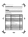
Contents
Location of the important labels ..... 1
Safety information ............................ 6
Description ........................................ 9
Control functions ............................ 12
Main switch .................................. 12
Starter (choke) lever (RST90) ...... 12
Throttle lever ................................ 12
Throttle override system
(T.O.R.S.) .................................. 13
Multi-function meter unit ............... 14
High beam indicator light .............. 17
Low coolant temperature indicator
light ............................................ 18
Fuel meter and grip/thumb warmer
level indicator ............................ 19
Fuel level warning indicator .......... 21
Oil level warning indicator
(RST90) ..................................... 21
Oil level/pressure warning indicator
(RS90P / RS90PLT /
RST90PGT) .............................. 22
Coolant temperature warning
indicator ..................................... 23
Electric power steering warning
indicator “EPS” (RS90P /
RS90PLT / RST90PGT) ............ 23
Self-diagnosis device ................... 23
Engine stop switch ....................... 24
Headlight beam switch
“LIGHTS” ................................... 24
Grip/thumb warmer adjusting
switch ........................................ 24
Auxiliary DC jack .......................... 25
Helmet shield heater jack (RS90P /
RS90PLT / RST90PGT) ............ 26
Brake lever ................................... 26
Parking brake lever ...................... 27
Shift lever ..................................... 27
Drive guard ................................... 28
V-belt holders ...............................
Passenger grips (RST90PGT) .....
Passenger grip warmer switch
(RST90 / RST90PGT) ...............
Passenger footrests
(RST90 / RST90PGT) ...............
Backrest (RST90 / RST90PGT) ...
Storage compartment (RS90P /
RS90PLT / RST90PGT) ...........
Storage areas (RST90) ................
Tow hitch bracket
(RST90 / RST90PGT) ...............
Fuel ..............................................
Suspension ..................................
29
30
30
31
31
32
34
36
37
38
Pre-operation checks ..................... 46
Pre-operation check list ............... 46
Operation ......................................... 48
Starting the engine ....................... 48
Break-in ........................................ 50
Riding your snowmobile ............... 50
Maximizing drive track life ............ 54
Driving .......................................... 55
Stopping the engine ..................... 56
Transporting ................................. 56
Periodic maintenance and
adjustment....................................... 58
Periodic maintenance chart for
the emission control system ..... 59
General maintenance and
lubrication chart ........................ 60
Tool kit ......................................... 62
Recommended equipment ........... 63
Removing and installing the shroud
and covers (RS90P / RS90PLT /
RST90PGT) .............................. 63
Opening and closing the shroud
and removing and installing
the right side cover (RST90) ..... 67
Checking the spark plugs ............. 68
U8HV10E0.book Page 2 Monday, May 16, 2011 1:15 PM
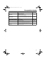
Contents
Adjusting the engine idling speed
(RST90) ..................................... 69
Adjusting the throttle lever free
play ............................................ 69
Checking the throttle override
system (T.O.R.S.) ..................... 72
Checking the air filter ................... 73
Carburetors (RST90) .................... 77
High-altitude settings .................... 77
Valve clearance ............................ 78
Engine oil and oil filter cartridge ... 78
Cooling system ............................. 84
V-belt ............................................ 88
Drive chain housing ...................... 91
Brake and parking brake .............. 93
Extrovert drive sprocket (RS90P /
RS90PLT / RST90PGT) ............ 95
Skis and ski runners ..................... 96
Steering system ........................... 97
Drive track and slide runners ....... 98
Lubrication .................................. 102
Replacing a headlight bulb ......... 104
Adjusting the headlight beams ... 107
Fittings and fasteners ................. 108
Battery ........................................ 108
Replacing a fuse ........................ 109
Troubleshooting ........................... 116
Storage .......................................... 121
Specifications ............................... 123
Consumer information.................. 126
Identification number records ..... 126
Vehicle Emission Control
Information label ...................... 127
YAMAHA MOTOR
CORPORATION, U.S.A.
SNOWMOBILE LIMITED
WARRANTY............................. 128
YAMAHA EXTENDED SERVICE
(Y.E.S.) .................................... 131
U8HV10E0.book Page 1 Monday, May 16, 2011 1:15 PM
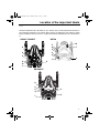
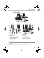
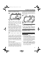
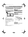
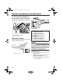
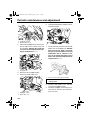
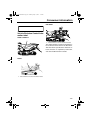
Location of the important labels
ESU10216
Read and understand all of the labels on your vehicle. They contain important information for
safe and proper operation of your vehicle. Never remove any labels from your vehicle. If a label
becomes difficult to read or comes off, a replacement label is available from your Yamaha dealer.
RS90P / RS90PLT
RST90
6
5
8
4
8
5
7
3
2
4
9
1
3
2
1
9
RST90PGT
8
5
3
4
1
2
9
1
U8HV10E0.book Page 2 Monday, May 16, 2011 1:15 PM
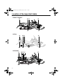
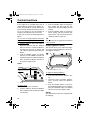
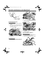
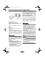
Location of the important labels
RS90P / RS90PLT
13
10 11
12
17
17
RST90
14
16
RST90PGT
14
16
2
12
15 11
10
17
10 15 11
17
12
17
17
U8HV10E0.book Page 3 Monday, May 16, 2011 1:15 PM
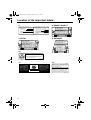
Location of the important labels
1 RS90P / RS90PLT
2
ATTENTION
8ET-2815K-10
1 RST90
3
NOTICE
8ET-2815K-00
1 RST90PGT
4
WARNING
SEVERE INJURY OR DEATH MAY RESULT IF YOU IGNORE ANY OF
THE FOLLOWING:
• Read the Owner’s Manual and all labels before operating this vehicle.
• This vehicle is a high performance machine.
It should be operated by an experienced operator.
• Check throttle, brake, and steering for proper operation before starting engine.
• Set parking brake before attempting to start engine.
Never run this vehicle with the parking brake applied.
• To stop engine in an emergency, push the engine stop switch down.
• Do not operate engine without drive belt or drive guard.
• Make sure the fuel tank cap is closed securely after refueling.
• Do not operate this vehicle on public roads.
You could collide with another vehicle.
• Check lever position (Forward or Reverse) before moving.
• Weal an approved helmet, eye protection, and adequate clothing
for snowmobiling.
AVERTISSEMENT
AFIN D’ÉVITER TOUT RISQUE DE BLESSURE SÉRIEUSE OU MÊME MORTELLE,
VEUILLEZ SUIVRE LES RECOMMANDATIONS SUIVANTES:
• Avant d’utiliser ce véhicule, lire le manuel du propriétaire et toutes les étiquettes.
• Ce véhicule est une machine à haute performance.
Elle doit être conduite par un conducteur expérimenté.
• Avant de démarrer le moteur, vérifier l’opération du frein, de l’accélérateur
et de la direction.
• Le frein de sécurité doit être appliqué lors du démarrage.
Ne pas rouler avec le frein de sécurité actionné.
• En cas d’urgence, utiliser l’interrupteur d’arrêt du moteur.
• Ne pas laisser tourner le moteur sans la courroie ou sans son garde.
• S’assurer que le bouchon du réservoir soit bien refermé après le remplissage.
• Afin d’éviter tout risque de collision, ne pas rouler sur un chemin public.
• Vérifier la position du levier (marche avant ou arrière) avant d’être en marche.
• Toujours porter un casque approuvé et un habillement de motoneigiste.
Prévoir une protection pour les yeux.
8HF-77761-E0
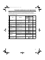
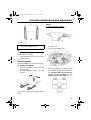
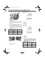
5 RS90P / RS90PLT / RST90PGT
TUNE-UP SPECIFICATIONS
ENGINE
1.SPARK PLUG
2.SPARK PLUG GAP
3.IDLE SPEED
CR8E(NGK)
0.7 ~ 0.8 mm (0.028 ~ 0.031 in)
1300 ± 50 r/min
SPECIFICATIONS DE LA MISE AU POINT
MOTEUR
8HF
1.TYPE DE BOUGIE
CR8E(NGK)
2.ECARTEMENT DES ÉLECTRODES 0.7 ~ 0.8 mm
3.RÉGIME DE RALENTI
1300 ± 50 r/min
8HF-1417E-00
5 RST90
6 RST90
TUNE-UP SPECIFICATIONS
ENGINE
1.SPARK PLUG
2.SPARK PLUG GAP
3.IDLE SPEED
CR8E(NGK)
0.7 ~ 0.8 mm (0.028 ~ 0.031 in)
1400 ± 100 r/min
SPECIFICATIONS DE LA MISE AU POINT
MOTEUR
8ES
1.TYPE DE BOUGIE
CR8E(NGK)
2.ECARTEMENT DES ÉLECTRODES 0.7 ~ 0.8 mm
3.RÉGIME DE RALENTI
1400 ± 100 r/min
8ES-1417E-00
7 RST90
NOTICE
ATTENTION
Severe engine damage
can result from oil loss if
crankcase breather hoses
are not installed correctly.
Inspect hoses and clamps
for correct installation
after battery service or
air box removal.
See Service Manual.
Des dommages graves risquent de survenir par
suite de fuites d’huile résultant d’un mauvais
branchement des tuyaux de reniflard du carter.
Après l’entretien de la batterie ou après la
dépose de I’épurateur d’air, assurezvous que les brides et les tuyaux
sont installès correctement.
Consultez le manuel
d’entretien.
8GS-2815J-E0
3
U8HV10E0.book Page 4 Monday, May 16, 2011 1:15 PM
Location of the important labels
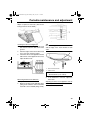
8
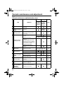
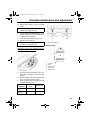
9 RS90P / RS90PLT
TUNE-UP SPECIFICATIONS
DRIVE
1. CHAIN CASE OIL Q’TY
2. CHAIN CASE OIL TYPE
250 cm³ (8.5 oz)
GL-3 75W or 80W
3. TRACK TENSION
30 ~ 35 mm (1.18 ~ 1.38 in)/100 N (10 kg, 22 lb)
* FOR MORE INFO: SEE SERVICE MANUAL FOR THIS
MODEL.
* SPECIFICATIONS SUBJECT TO CHANGE WITHOUT
NOTICE.
8FR-77763-E0
SPECIFICATIONS DE LA MISE AU POINT
ENTRAÎNEMENT
1. CAPACITÉ D’HUILE DU CARTER DE CHAÎNE
250 cm³
2. TYPE D’HUILE DU CARTER DE CHAÎNE
GL-3 75W or 80W
3. FLÈCHE DE LA CHENILLE
30 ~ 35 mm/100 N (10 kg)
* POUR PLUS DE DÉTAIL: VOIR LE MANUEL D’ATELIER
POUR CE MODÈLE.
* LES CARACTÉRISTIQUE TECHNIQUES SONT
SUSCEPTIBLES DE CHANGER SANS NOTIFICATION
PRÉALABLE.
8ES-47578-00
9 RST90
9 RST90PGT
8ER-E0
8ER-77763-E0
8HF-77763-E0
ANADA •
•C
VAC •
NS
506
T
RA
T
• CMVSS
10
NSPO
R
This spark ignition system meets all requirements of the
Canadian Interference Causing Equipment Regulations.
Ce système d’allumage par étincelle de véhicule
respecte toutes les exigences du Règlement sur le
matériel brouilleur du Canada.
3JK-82377-10
11
12
8FA-E0
JUMPER CABLE CONNECTION LEADS
• For connecting procedures, refer to
Owner’s Manual.
FILS DE BRANCHEMENT DES CÂBLES
DE DÉMARRAGE
• Effectuer le branchement des câbles
de démarrage conformément aux
instructions du Manuel du propriétaire.
88C-77769-00
8FA-2389C-E0
4
U8HV10E0.book Page 5 Monday, May 16, 2011 1:15 PM
Location of the important labels
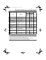
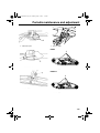
13 RS90PLT
14 RST90 / RST90PGT
LOAD LIMIT / CHARGE LIMITE
10kg {22lbs}
8ET-24897-00
15 RST90 / RST90PGT
LOAD LIMIT / CHARGE LIMITE
20kg {44lbs}
8FM-24897-01
MAX. TOWING FORCE
MAX. VERTICAL FORCE
FORCE DE REMORQUAGE MAX. FORCE VERTICALE MAX.
1176 N (120 kgf), 264 lbf 147 N (15 kgf), 33 lbf
8GS-2817S-E0
16 RST90 / RST90PGT
17 RST90
17 RS90P / RS90PLT / RST90PGT
5
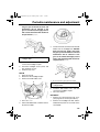
U8HV10E0.book Page 6 Monday, May 16, 2011 1:15 PM
Safety information
ESU10193
As the vehicle’s owner, you are responsible
for the safe and proper operation of your
snowmobile. When you ride your snowmobile, you must know and use the following for
your safety. Severe injury or death may result
if you ignore any of the following.
Before you operate your snowmobile
●
●
Read the Owner’s Manual and all labels.
Become familiar with all of the operating
controls and their function. Consult a
Yamaha dealer about any control or function you do not understand.
Wear protective clothing. Wear an approved helmet, and a face shield or goggles. Also, wear a good quality snowmobile
suit, boots, and a pair of gloves or mittens
that will permit use of your thumbs and fingers for operation of the controls.
●
While using your snowmobile
●
●
●
●
Do not operate the snowmobile after or
while drinking alcohol or taking drugs. Your
ability to operate the snowmobile is reduced by the influence of alcohol or drugs.
Prepare your snowmobile
●
6
Perform the pre-operation checks each
time you use the vehicle to make sure it is
in safe operating condition. Failure to inspect or maintain the vehicle properly in-
creases the possibility of an accident or
equipment damage. See page 46 for a list
of pre-operation checks.
Apply the parking brake before starting the
engine. Never drive the snowmobile with
the parking brake applied. This may overheat the brake disc and reduce braking ability.
●
This snowmobile was not manufactured for
use on public streets, roads, or highways.
Such use is prohibited by law, and you
could collide with another vehicle.
RS90P and RS90PLT are designed to carry
the OPERATOR ONLY. Passengers are
prohibited. Carrying a passenger can cause
loss of control.
Be careful where you ride. There may be
obstacles hidden beneath the snow. Stay
on established trails to minimize your exposure to hazards. Ride slowly and cautiously
when you ride off of established trails. Hitting a rock or stump, or running into wires
could cause an accident and injury.
This snowmobile is not designed for use on
surfaces other than snow or ice. Use on dirt,
sand, grass, rocks, or bare pavement may
cause loss of control and may damage the
snowmobile.
U8HV10E0.book Page 7 Monday, May 16, 2011 1:15 PM
Safety information
●
●
Always ride with other snowmobilers when
going on a ride. You may need help if you
run out of fuel, have an accident, or damage
your snowmobile.
Many surfaces such as ice and hardpacked
snow require much longer stopping distances. Be alert, plan ahead and begin decelerating early. The best braking method on
most surfaces is to release the throttle and
apply the brake gently—not suddenly.
Avoid carbon monoxide poisoning
All engine exhaust contains carbon monoxide, a deadly gas. Breathing carbon monoxide
can cause headaches, dizziness, drowsiness,
nausea, confusion, and eventually death.
Carbon monoxide is a colorless, odorless,
tasteless gas which may be present even if
you do not see or smell any engine exhaust.
Deadly levels of carbon monoxide can collect
rapidly and you can quickly be overcome and
be unable to save yourself. Also, deadly levels of carbon monoxide can linger for hours or
days in enclosed or poorly-ventilated areas. If
you experience any symptoms of carbon
monoxide poisoning, leave the area immediately, get fresh air, and SEEK MEDICAL
TREATMENT.
● Do not run the engine indoors. Even if you
try to ventilate engine exhaust with fans or
open windows and doors, carbon monoxide
can rapidly reach dangerous levels.
● Do not run the engine in poorly ventilated or
partially enclosed areas such as barns, garages, or carports.
● Do not run the engine outdoors where engine exhaust can be drawn into a building
through openings such as windows and
doors.
Genuine Yamaha Accessories
Choosing accessories for your snowmobile is
an important decision. Genuine Yamaha Accessories, which are available only from a
Yamaha dealer, have been designed, tested,
and approved by Yamaha for use on your
snowmobile. Many companies with no connection to Yamaha manufacture parts and accessories or offer other modifications for
Yamaha vehicles. Yamaha is not in a position
to test the products that these aftermarket
companies produce. Therefore, Yamaha can
neither endorse nor recommend the use of
accessories not sold by Yamaha or modifications not specifically recommended by
Yamaha, even if sold and installed by a
Yamaha dealer.
Maintenance and storage
●
●
●
●
●
When laying the snowmobile on its side for
maintenance, use a suitable stand to keep
it in a stable and level position.
Do not leave the snowmobile on its left side
for an extended period of time. Fuel may
leak out from the fuel breather hose.
Do not allow anyone to stand behind the
snowmobile when starting, inspecting, or
adjusting the snowmobile. A broken track,
track fittings, or debris thrown by the track
could be dangerous to the operator or bystanders.
Modifications made to the snowmobile not
approved by Yamaha, or the removal of
original equipment may render your snowmobile unsafe for use, which may cause severe personal injury. Modifications may
also make the snowmobile illegal to use.
Never store the snowmobile with fuel in the
fuel tank inside a building where ignition
sources are present such as hot water and
space heaters, an open flame, sparks,
7
U8HV10E0.book Page 8 Monday, May 16, 2011 1:15 PM
Safety information
clothes dryers, and the like. Allow the engine to cool off before storing the snowmobile in an enclosed space.
8
U8HV10E0.book Page 9 Monday, May 16, 2011 3:37 PM
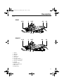
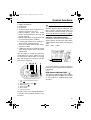
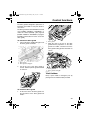
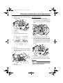
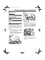
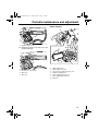
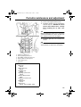
Description
ESU10261
RS90P
1,2,3
4
5,6,7
13 12
8,9
10
11
RS90PLT
1,2,3
4
5,6,7
13
12
8,9
10
11
1. Battery
2. Main fuse
3. Air filter
4. Oil filler cap
5. Fuse box
6. Coolant reservoir
7. Coolant recovery tank
8. Storage compartment
9. Tool kit
10. Tail/brake light
11. Slide rail suspension
12. Drive track
13. V-belt holder
9
U8HV10E0.book Page 10 Monday, May 16, 2011 1:15 PM
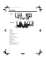
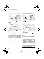
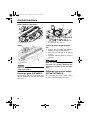
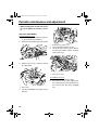
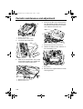
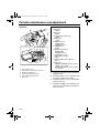
Description
10,12 1,2,3,4 20 5,6
7 8 9 19 13 14
RST90
17
1,2,3
4
16
5,6
15
7 8
9 10,11,12 13 14
RST90PGT
17
1. Battery
2. Main fuse
3. Air filter
4. Oil filler cap
5. Fuse box
6. Coolant reservoir
7. Passenger grip warmer switch
8. Passenger grip
9. Backrest
10. Storage compartment
11. Storage pouch (RST90PGT)
12. Tool kit
13. Tail/brake light
14. Tow hitch bracket
15. Slide rail suspension
16. Drive track
17. V-belt holder
18. Solo touring storage area (RST90)
19. Rear carrier (RST90)
20. Throttle stop screw (RST90)
10
16
18
15
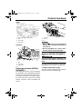
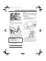
U8HV10E0.book Page 11 Monday, May 16, 2011 1:15 PM
Description
RS90P / RS90PLT
12 3
467
8
11
5
10
RST90
1 2
9
3 11
RST90PGT
1
2 3 5
6 4 7
9
12
12
4 6 7
11
8
10
9
13 10
1.
2.
3.
4.
5.
8
Brake lever
Parking brake lever
Grip warmer adjusting switch
Thumb warmer adjusting switch
Helmet shield heater jack (RS90P /
RS90PLT / RST90PGT)
6. Engine stop switch
7. Throttle lever
8. Main switch
9. Shift lever
10. Auxiliary DC jack
11. Headlight beam switch
12. Shroud latch (RST90)
13. Starter (choke) lever (RST90)
TIP
●
●
The snowmobile you have purchased may differ slightly from those shown in the figures of
this manual.
Design and specifications are subjected to change without notice.
11
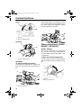
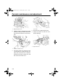
U8HV10E0.book Page 12 Monday, May 16, 2011 1:15 PM
Control functions
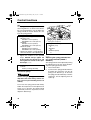
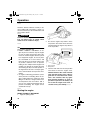
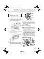
ESU13740
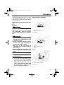
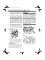
Main switch
The main switch controls the ignition and
lighting systems. The various positions are
described below.
1
2
3
1. Starter (choke) lever
TIP
Refer to the “Starting the engine” section on
page 48 for proper operation.
1. Off
2. On
3. Start
Off
The ignition circuit is switched off.
The key can be removed only in this position.
On
The ignition circuit is switched on.
Start
The starting circuit is switched on.
The starter motor cranks the engine.
NOTICE: Release the switch immediately
after the engine starts. [ECS00021]
TIP
●
●
RS90P / RS90PLT / RST90PGT: The
headlights and taillight come on after the
engine is started.
RST90: The headlights, meter lighting, and
taillights come on after the engine is started.
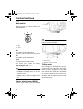
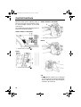
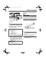
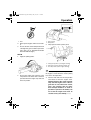
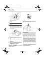
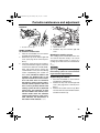
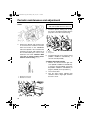
ESU10301
Starter (choke) lever (RST90)
Use the starter (choke) lever when starting
and warming up a cold engine.
12
1. When starting a cold engine.
2. Warming up
3. When the engine is warm.
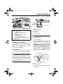
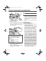
ESU10312
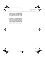
Throttle lever
Once the engine is running cleanly, squeezing the throttle lever will increase the engine
speed and cause engagement of the drive
train. Regulate the speed of the snowmobile
by varying the throttle position. Because the
throttle is spring-loaded, the snowmobile will
decelerate, and the engine will return to idle
when it is released.
U8HV10E0.book Page 13 Monday, May 16, 2011 1:15 PM
Control functions
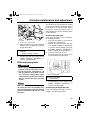
1. Throttle lever
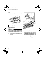
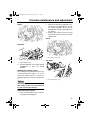
ESU13750
Throttle override system
(T.O.R.S.)
EWS00041
WARNING
If the T.O.R.S. is activated, make sure that
the cause of the malfunction has been corrected and that the engine can be operated
without a problem before restarting the
engine. Continuing to operate with a malfunction could cause loss of control or
damage.
If the throttle valves or throttle cable malfunctions during operation, the T.O.R.S. will be activated when the throttle lever is released.
The T.O.R.S. is designed to override the fuel
injection (RS90P / RS90PLT / RST90PGT)
or ignition (RST90) and limit the engine
speed to less than the clutch engagement
speed if the throttle valves fail to return to the
idle position when the throttle lever is released. (See page 123 for the clutch engagement speed.)
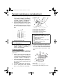
Idling
Riding
Malfunction
Throttle
lever
Released
Squeezed
Released
Throttle
valve
Closed
Open
Open
T.O.R.S.
Engine
runs
properly.
Engine
runs
properly.
T.O.R.S.
will be activated.
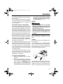
TIP
If the T.O.R.S. is activated, the warning light
and engine trouble warning indicator flash,
and the two-digit code “84” displays (RS90P /
RS90PLT / RST90PGT) or flashes (RST90)
in the meter display. If this occurs, have a
Yamaha dealer check the system as soon as
possible.
RS90P / RS90PLT / RST90PGT
1. Warning light “ ”
2. Engine trouble warning indicator “
3. Two-digit code “84”
”
13
U8HV10E0.book Page 14 Monday, May 16, 2011 1:15 PM
Control functions
RST90
● a display brightness control function
When the key is turned to the on position, the
tachometer needle makes one sweep, and
the low coolant temperature indicator light,
the warning light, and all segments of the
meter unit display come on and go off.
12
3
4 5
6
7
8
9
FHI
E LO
1. Warning light “ ”
2. Engine trouble warning indicator “
3. Two-digit code “84”
EPS
”
10
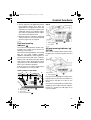
ESU14101
Multi-function meter unit
RS90P / RS90PLT / RST90PGT
The multi-function meter unit is equipped with
the following:
● a digital speedometer
● a tachometer
● an odometer
● two tripmeters (which show the distance
traveled since they were last set to zero)
● a fuel reserve tripmeter (which shows the
distance traveled since the fuel level warning indicator and warning light came on)
● an oil change tripmeter (which shows the
distance traveled since the periodic oil
change interval was reached)
● a clock
● warning indicators (which show engine
trouble, coolant temperature, fuel level, and
oil level warnings)
● indicator lights (which show high beam and
low coolant temperature conditions)
● a warning light (which shows warnings together with the warning indicators)
● a fuel meter (which shows the fuel remaining in the fuel tank)
● a grip/thumb warmer level indicator (which
shows the grip warmer level or the thumb
warmer level)
14
1.
2.
3.
4.
5.
6.
“RESET” button
“SELECT” button
Tachometer
Warning indicators
Clock
Low coolant temperature indicator
light “
”
7. High beam indicator light “
”
8. Warning light “ ”
9. Electric power steering warning indicator
“EPS”
10. Meter display
The grip warmer level is initially displayed for
5 seconds, then the display switches to the
fuel meter.
TIP
To switch the speedometer, odometer, and
tripmeter displays between kilometers and
miles, select the odometer mode “ODO”, and
then push the “SELECT” button for at least 10
seconds while the snowmobile is stopped.
U8HV10E0.book Page 15 Monday, May 16, 2011 1:15 PM
Control functions
Odometer and tripmeter modes
counting the distance traveled from that point.
When this occurs, change the engine oil as
soon as possible. (See page 78 for the oil
change procedure.)
E LO
E LO
1
1. Odometer/tripmeter/fuel reserve tripmeter
Pushing the “SELECT” button switches the
display between the odometer mode “ODO”
and the tripmeter modes “TRIP A” and “TRIP
B” in the following order:
ODO → TRIP A → TRIP B → ODO
If the fuel level warning indicator and warning
light come on (see page 19), the odometer
display will automatically change to the fuel
reserve tripmeter mode “TRIP F” and start
counting the distance traveled from that point.
In that case, push the “SELECT” button to
switch the display between the various tripmeter and odometer modes in the following
order:
TRIP F → ODO → TRIP A → TRIP B → TRIP
F
To reset a tripmeter, select it by pushing the
“SELECT” button, and then push the “RESET” button for at least 1 second. If you do not
reset the fuel reserve tripmeter manually, it
will reset itself automatically, and the display
will return to the prior mode after the snowmobile has been refueled and traveled 5 km (3
mi).
Oil change tripmeter
When the periodic oil change interval is
reached at the initial 800 km (500 mi), then at
every 4000 km (2500 mi) thereafter, the oil
change tripmeter and “OIL” flash alternately in
the odometer display, and the tripmeter starts
TIP
●
●
The oil change tripmeter will flash only
when the snowmobile is stopped.
To return to the previous display mode,
push the “SELECT” button. To display the
oil change tripmeter again, turn the key to
the off position, then back to the on position.
After changing the engine oil, reset the oil
change tripmeter as follows.
To reset the oil change tripmeter (when the
engine oil was changed after the oil change
tripmeter appeared)
1. To display the oil change tripmeter, turn
the key to the on position.
2. Push the “RESET” button for at least 1
second while the oil change tripmeter and
“OIL” are flashing alternately in the odometer display. The distance traveled since
the last oil change and “OIL” will flash alternately in the odometer display.
3. Push the “RESET” button for approximately 3 seconds. “00000” and “OIL” will
flash alternately in the odometer display 3
times, and then the display will return to
the previous display mode.
15
U8HV10E0.book Page 16 Monday, May 16, 2011 1:15 PM
Control functions
If the engine oil is changed before the oil
change tripmeter appears in the display (i.e.,
before the periodic oil change interval has
been reached), the tripmeter must be reset after the oil change for the next periodic oil
change to be indicated at the correct time.
In that case, reset the oil change tripmeter as
follows.
3.
To reset the oil change tripmeter (when the
engine oil was changed before the oil change
tripmeter appeared)
1. Push the “SELECT” button until “ODO” is
displayed, and then push the “RESET”
button for at least 1 second. The distance
traveled since the last oil change and
“OIL” will flash alternately in the odometer
display.
2. Push the “RESET” button for approximately 3 seconds. “00000” and “OIL” will
flash alternately in the odometer display 3
times, and then the display will return to
the previous display mode.
TIP
4.
Push the “RESET” button to change the
hour setting, and then push the “SELECT” button. The minute digits will start
flashing.
Push the “RESET” button to change the
minute setting, and then push the “SELECT” button. The clock starts when the
“SELECT” button is released.
The clock must be set again when the battery
is disconnected.
Display brightness control
This function allows you to adjust the brightness of the meter unit display to suit the outdoor lighting conditions.
Clock
1
1
1. Display brightness level
F
E
1. Clock
To set the clock
1. Turn the key to the on position.
2. Push the “SELECT” button and “RESET”
button simultaneously until the hour digits
start flashing.
To adjust the display brightness
1. Turn the key to the off position.
2. Push and hold down the “SELECT” button.
3. Turn the key to the on position, and then,
after 5 seconds, release the “SELECT”
button.
4. Push the “RESET” button to select the
desired display brightness level, and then
push the “SELECT” button. The display
returns to the previous display mode.
RST90
The multi-function meter unit is equipped with
the following:
16
U8HV10E0.book Page 17 Monday, May 16, 2011 1:15 PM
Control functions
a digital speedometer
a tachometer
● an odometer
● a tripmeter (which shows the distance traveled since it was last set to zero)
● warning indicators (which show engine
trouble, coolant temperature, fuel level, and
oil level warnings)
● indicator lights (which show high beam and
low coolant temperature conditions)
● a warning light (which shows warnings together with the warning indicators)
● a fuel meter (which shows the fuel remaining in the fuel tank)
● a grip/thumb warmer level indicator (which
shows the grip warmer level or the thumb
warmer level)
After the engine is started, the tachometer
needle makes one sweep, and the low coolant temperature indicator light, the warning
light, and all segments of the meter unit display come on and go off.
●
●
1
2345 6
7
TIP
To switch the speedometer, odometer, and
tripmeter displays between kilometers and
miles, select the odometer mode “ODO”, and
then push the select/reset button for at least
10 seconds while the snowmobile is stopped.
Odometer and tripmeter modes
Pushing the select/reset button switches the
display between the odometer mode “ODO”
and the tripmeter mode “TRIP” in the following
order:
ODO → TRIP → ODO
1
1. Odometer/tripmeter
To reset the tripmeter, push the select/reset
button for at least 1 second while the tripmeter
is displayed.
ESU10411
High beam indicator light “
1. Tachometer
2. Low coolant temperature indicator
light “
”
3. High beam indicator light “
”
4. Warning light “ ”
5. Warning indicators
6. Meter display
7. Select/reset button
”
The high beam indicator light comes on when
the high beams of the headlights are switched
on. (See page 24 for headlight beam switch
operation.)
The grip warmer level is initially displayed for
5 seconds, then the display switches to the
fuel meter.
17
U8HV10E0.book Page 18 Monday, May 16, 2011 1:15 PM
Control functions
RS90P / RS90PLT / RST90PGT
1. High beam indicator light “
RS90P / RS90PLT / RST90PGT
”
1. Low coolant temperature indicator
light “
”
RST90
RST90
1. High beam indicator light “
”
1. Low coolant temperature indicator
light “
”
2. Warning light “ ”
3. Engine trouble warning indicator “
4. Two-digit code “86”
ESU13761
Low coolant temperature indicator light “ ”
The low coolant temperature indicator light
comes on when the coolant temperature is
low and informs the rider that the snowmobile
should be warmed up. After the engine is
started, warm it up until the indicator light
goes off.
The snowmobile can be operated normally after the indicator light goes off.
TIP
●
●
18
”
RS90P / RS90PLT / RST90PGT: Drive the
snowmobile at low speeds when the low
coolant temperature indicator light is on. If
the engine speed is too high, maximum engine speed is reduced to protect the engine.
RST90: Drive the snowmobile at low
speeds when the low coolant temperature
indicator light is on. If the engine speed is
too high, the warning light and engine trouble warning indicator flash and the two-digit
code “86” flashes in the error code display.
When this occurs, maximum engine speed
is reduced to protect the engine.
U8HV10E0.book Page 19 Monday, May 16, 2011 1:15 PM
Control functions
ESU10426
Fuel meter and grip/thumb
warmer level indicator
RS90P / RS90PLT / RST90PGT
The fuel meter and grip/thumb warmer level
indicator have eight segments which show
the amount of fuel remaining in the fuel tank,
the grip warmer level, or the thumb warmer
level.
RS90P / RS90PLT / RST90PGT
1. Fuel level warning indicator “
2. Warning light “ ”
”
RST90
1. Fuel meter and grip/thumb warmer level indicator
RST90
1. Fuel level warning indicator “
2. Warning light “ ”
”
If the fuel level warning indicator and the
warning light come on, refuel as soon as possible.
TIP
1. Fuel meter and grip/thumb warmer level indicator
Fuel meter
The display segments of the fuel meter disappear towards “E” (Empty) as the fuel level decreases. When only one segment is left near
“E”, the fuel level warning indicator and the
warning light come on.
The snowmobile must be stopped on a level
surface to obtain an accurate fuel meter reading, since the reading changes according to
the movement and inclination of the snowmobile.
Grip/thumb warmer level indicator
When the grip warmer adjusting switch is
pressed, the grip warmer indicator comes on
and the display switches to the grip warmer
level.
19
U8HV10E0.book Page 20 Monday, May 16, 2011 1:15 PM
Control functions
When the thumb warmer adjusting switch is
pressed, the thumb warmer indicator comes
on and the display switches to the thumb
warmer level.
See “Grip/thumb warmer adjusting switch” on
page 24 for detailed information.
RS90P / RS90PLT / RST90PGT
1
RS90P / RS90PLT / RST90PGT
1. Grip warmer adjusting switch
RST90
1
1. Grip warmer indicator “
”
2. Thumb warmer indicator “
”
RST90
1. Grip warmer adjusting switch
1. Grip warmer indicator “
”
2. Thumb warmer indicator “
”
1. Thumb warmer adjusting switch
TIP
●
20
The grip/thumb warmer level is displayed
for 5 seconds after releasing the grip/thumb
warmer adjusting switch, then the display
switches to the fuel meter.
U8HV10E0.book Page 21 Monday, May 16, 2011 1:15 PM
Control functions
●
●
The top segment of the grip/thumb warmer
level indicator flashes once when the
grip/thumb warmer adjustment reaches the
maximum level. The bottom segment of the
grip/thumb warmer level indicator flashes
once when the grip/thumb warmer adjustment reaches the minimum level.
When the engine is started, the grip/thumb
warmer levels are set to the levels selected
when the engine was last stopped.
RST90
1. Fuel level warning indicator “
2. Warning light “ ”
3. Fuel meter
ESU13252
Fuel level warning
indicator “ ”
The fuel level warning indicator and the warning light come on when the fuel level is low.
(See page 19 for details.)
The fuel level warning indicator, the warning
light, the fuel meter indicator (RS90P /
RS90PLT / RST90PGT), and all segments of
the fuel meter start to flash when a malfunctioning sensor, disconnected coupler, broken
lead, or short circuit is detected by the self-diagnosis device of the snowmobile to warn the
rider of any of the above problems.
If this occurs, have a Yamaha dealer inspect
the snowmobile as soon as possible.
”
ESU10463
Oil level warning indicator “ ”
(RST90)
The oil level warning indicator and the warning light come on when the engine oil level is
low.
RS90P / RS90PLT / RST90PGT
3
1.
2.
3.
4.
4
1
Fuel level warning indicator “
Warning light “ ”
Fuel meter
Fuel meter indicator “ ”
2
”
1. Oil level warning indicator “
2. Warning light “ ”
”
If the oil level warning indicator and the warning light come on, place the snowmobile on a
level surface and allow it to idle for one
minute.
If the oil level warning indicator and the warning light go off, the engine oil level is sufficient,
however it is getting low. Add engine oil as
soon as possible.
21
U8HV10E0.book Page 22 Monday, May 16, 2011 1:15 PM
Control functions
If the oil level warning indicator and the warning light do not go off, check the engine oil level in the oil tank (see page 78 for engine oil
level checking procedures), and add engine
oil if necessary.
If the oil level warning indicator and the warning light still remain on, have a Yamaha dealer
check the snowmobile.
If the warning indicator and the warning light
do not go off, check the engine oil level in the
oil tank (see page 78 for engine oil level
checking procedures), and add engine oil if
necessary.
If the warning indicator and the warning light
still remain on, have a Yamaha dealer check
the snowmobile.
ESU13991
Oil pressure warning
Oil level/pressure warning
indicator “ ” (RS90P /
RS90PLT / RST90PGT)
The oil level/pressure warning indicator has
two functions. The warning indicator comes
on when the engine oil level is low and when
the engine oil pressure is low. The functions
are explained in the following sections.
Oil level warning
The warning indicator and the warning light
come on when the engine oil level is low.
The warning indicator comes on and “OP-LO”
(oil pressure low) appears in the odometer
display if the engine oil pressure is low when
the engine is started. At the same time, the
engine speed is limited to less than the clutch
engagement speed until the warning indicator
goes off.
If the engine oil pressure remains low for one
minute, the engine stops. If this occurs, have
a Yamaha dealer check the snowmobile.
1
2
1. Oil level/pressure warning indicator “
2. Warning light “ ”
”
If the warning indicator and the warning light
come on, place the snowmobile on a level
surface and allow it to idle for one minute.
If the warning indicator and the warning light
go off, the engine oil level is sufficient, however it is getting low. Add engine oil as soon as
possible.
22
1. Oil level/pressure warning indicator “
2. “OP-LO” (oil pressure low)
”
TIP
If there is no engine oil in the oil passages
when the engine is started, such as after the
engine oil is changed, the warning indicator
may come on and “OP-LO” may appear in the
odometer display for a few seconds until the
oil circulates through the engine. The snowmobile can be operated normally after the
warning indicator goes off.
U8HV10E0.book Page 23 Monday, May 16, 2011 1:15 PM
Control functions
ESU10513
ESU13812
Coolant temperature warning
indicator “ ”
Electric power steering warning
indicator “EPS” (RS90P /
RS90PLT / RST90PGT)
If the engine overheats, the coolant temperature warning indicator and the warning light
come on. When this occurs, stop the engine
immediately and allow the engine to cool
down, and then check the coolant level in the
coolant reservoir. (See page 84 for checking
procedures.)
RS90P / RS90PLT / RST90PGT
1. Coolant temperature warning indicator “
2. Warning light “ ”
The electric power steering warning indicator
comes on when the key is turned to the on position, and then goes off once the engine is
started. If the warning indicator remains on or
comes on after the engine is started, the EPS
system may not be working correctly. When
this occurs, have a Yamaha dealer check the
EPS system.
”
1. Electric power steering warning indicator
“EPS”
RST90
TIP
If the steering load is too heavy (i.e., excessive steering use when the snowmobile is
traveling at a slow speed), the power assist is
reduced to protect the EPS motor from overheating.
ESU13771
Self-diagnosis device
1. Coolant temperature warning indicator “
2. Warning light “ ”
”
ECS00041
NOTICE
Do not continue to operate the engine if it
is overheating.
This model is equipped with a self-diagnosis
device for various electrical circuits.
If a problem is detected in any of those circuits, the warning light and the engine trouble
warning indicator flash, and an error code displays (RS90P / RS90PLT / RST90PGT) or
flashes slowly (RST90) in the meter display.
Note the error code, and then have a Yamaha
dealer inspect the snowmobile as soon as
possible. NOTICE: Do not continue to oper-
23
U8HV10E0.book Page 24 Monday, May 16, 2011 1:15 PM
Control functions
ate the engine longer than necessary if
there is an error code to avoid possible engine damage. [ECS00820]
RS90P / RS90PLT / RST90PGT
2
3
1
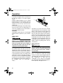
1. Engine stop switch “
”
During the first few rides, practice using the
stop switch so that you can react quickly in an
emergency.
1. Warning light “ ”
2. Engine trouble warning indicator “
3. Error code display
ESU10661
”
Headlight beam switch
“LIGHTS”
Push the headlight beam switch to change the
headlight to high beam “HI” or to low beam
“LO”.
RST90
1
2
3
1. Warning light “ ”
2. Engine trouble warning indicator “
3. Error code display
”
ESU10531
Engine stop switch “ ”
The engine stop switch is used to stop the engine in an emergency. Simply push the stop
switch to stop the engine. To start the engine,
pull the stop switch and proceed with starting
the engine. (See page 48 for engine starting
procedures.)
24
1. Headlight beam switch “LIGHTS”
2. High beam “HI”
3. Low beam “LO”
ESU12654
Grip/thumb warmer adjusting
switch
The grip warmer adjusting switch and the
thumb warmer adjusting switch control the
electrically heated handlebar grips and throttle lever respectively.
U8HV10E0.book Page 25 Monday, May 16, 2011 1:15 PM
Control functions
RS90P / RS90PLT / RST90PGT
1
See “Fuel meter and grip/thumb warmer level
indicator” on page 19 for detailed information.
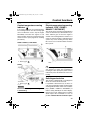
ESU10696
Auxiliary DC jack
The auxiliary DC jack is located in the front
panel and can be used for accessories.
TIP
The auxiliary DC jack can only be used if the
engine is running.
1. Grip warmer adjusting switch
To use the auxiliary DC jack
1.
2.
RST90
1
Start the engine.
Open the auxiliary DC jack cap, and then
insert the accessory power plug into the
jack.
RS90P / RS90PLT / RST90PGT
1
1. Grip warmer adjusting switch
2
1. Auxiliary DC jack cap
2. Auxiliary DC jack
RST90
1. Thumb warmer adjusting switch
To raise the temperature
To raise the temperature, press the respective switch to “HI”.
To lower the temperature
To lower the temperature, press the respective switch to “LO”.
1. Auxiliary DC jack cap
2. Auxiliary DC jack
25
U8HV10E0.book Page 26 Monday, May 16, 2011 1:15 PM
Control functions
3.
After using the auxiliary DC jack, be sure
to remove the accessory power plug from
the jack and to close the auxiliary DC jack
cap.
1
2
ECS00122
NOTICE
●
●
To avoid circuit overload and a possible
fuse blowing, do not use accessories requiring more than the maximum rated
capacity for the auxiliary DC jack. (See
page 109 for the specified fuse amperage.)
Do not use an automotive cigarette lighter or other accessory with a plug that
gets hot because the jack can be damaged.
1. Helmet shield heater jack cap
2. Helmet shield heater jack
3.
After using the helmet shield heater, be
sure to remove its power plug from the
jack and to close the jack cap.
ECS00892
NOTICE
Maximum rated capacity:
DC 12 V, 2.5 A (30 W)
ESU13264
Helmet shield heater jack
(RS90P / RS90PLT / RST90PGT)
The helmet shield heater jack is located on
the left side of the handlebar.
TIP
The helmet shield heater jack can only be
used if the engine is running.
To use the helmet shield heater jack
1.
2.
26
Start the engine.
Open the helmet shield heater jack cap,
and then insert the power plug of the helmet shield heater into the jack.
To avoid circuit overload and a possible
fuse blowing, do not use a helmet shield
heater requiring more than the maximum
rated capacity for the helmet shield heater
jack. (See page 109 for the specified fuse
amperage.)
Maximum rated capacity:
DC 12 V, 1.5 A (18 W)
ESU10551
Brake lever
The snowmobile is stopped by braking the entire drive system.
Squeeze the brake lever towards the handlebar grip to stop the snowmobile.
U8HV10E0.book Page 27 Monday, May 16, 2011 1:15 PM
Control functions
1. Brake lever
TIP
When the brake lever is squeezed, the brake
light comes on.
ECS00060
NOTICE
Make sure that the brake lever end does
not project out over the handlebar end.
This will help prevent brake lever damage
when the snowmobile is placed on its side
for service.
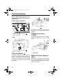
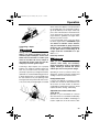
ESU10581
Parking brake lever
ESU10593
Shift lever
The shift lever is used to put the snowmobile
into forward or reverse. After coming to a
complete stop, pull the shift lever out, slide it
to “FWD” or to “REV” until it stops, and then
release it.
RS90P / RS90PLT / RST90PGT
1
When parking the snowmobile or starting the
engine, apply the parking brake by moving the
parking brake lever to the left.
1. Shift lever
1
1. Parking brake lever
To release the parking brake, move the parking brake lever to the right.
2
3
1. Pull out.
2. Slide to “FWD” (forward).
3. Release.
27
U8HV10E0.book Page 28 Monday, May 16, 2011 1:15 PM
Control functions
3
2
1
1. Pull out.
2. Slide to “REV” (reverse).
3. Release.
1. Pull out.
2. Slide to “REV” (reverse).
3. Release.
ECS00072
RST90
NOTICE
Do not use the shift lever while the snowmobile is moving, otherwise the drive train
could be damaged.
ESU14092
Drive guard
EWS00402
WARNING
●
1. Shift lever
●
Coming in contact with the rotating Vbelt or clutch parts can cause severe injury or death. Never run the engine with
the drive guard removed.
Make sure that the drive guard is installed securely before operating the
snowmobile to protect against severe
injury or death from a broken V-belt or
other part should it come off the snowmobile while it is in operation.
ECS00930
NOTICE
1. Pull out.
2. Slide to “FWD” (forward).
3. Release.
●
●
28
Never run the engine with the V-belt removed. Clutch components can be damaged.
Be careful not to scratch the windshield
when removing or installing the drive
guard.
U8HV10E0.book Page 29 Monday, May 16, 2011 1:15 PM
Control functions
The drive guard is designed to protect the Vbelt clutch and V-belt in case parts break or
come loose.
The drive guard is located behind the left side
cover (RS90P / RS90PLT / RST90PGT), or
under the shroud (RST90). [See page 63
(RS90P / RS90PLT / RST90PGT) or page 67
(RST90) for information on how to access the
drive guard.]
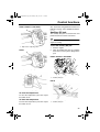
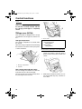
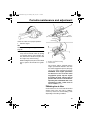
To remove the drive guard
1.
1
1. Drive guard
Pull out the drive guard locking pin from
the drive guard rear holder.
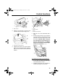
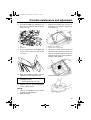
2
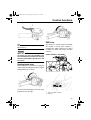
2.
Align the slots in the rear of the drive
guard with the projections on the drive
guard rear holder, and then insert the
drive guard locking pin into the holder as
shown.
1
1
2
1. Drive guard
2. Drive guard locking pin
2.
Lift up the rear of the drive guard as
shown, and then pull the guard rearward
to remove it.
1. Drive guard
2. Drive guard locking pin
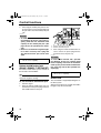
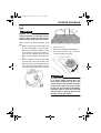
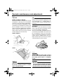
ESU10761
V-belt holders
Keep a spare V-belt for emergency use by
placing it into the V-belt holders provided.
To install the drive guard
1.
Fit the front slots in the drive guard over
the projections on the drive guard front
holder.
29
U8HV10E0.book Page 30 Monday, May 16, 2011 1:15 PM
Control functions
RS90P / RS90PLT / RST90PGT
1
2
1
1. V-belt holder
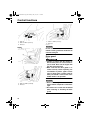
RST90
1. Passenger grip
2. Passenger grip adjusting knob
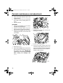
To change the passenger grip position
1.
2.
3.
Remove the passenger grip adjusting
knob by turning it counterclockwise.
Move the passenger grip to the desired
position.
Install the adjusting knob by turning it
clockwise.
EWS00780
WARNING
1. V-belt holder
ECS00180
NOTICE
Make sure that the V-belt is installed securely in the holders.
Make sure that the passenger grip adjusting knobs are securely tightened after
changing the positions of the passenger
grips.
ESU10681
ESU13302
Passenger grips (RST90PGT)
The passenger grips can be installed in three
different positions to suit the passenger’s
preference.
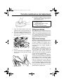
30
Passenger grip warmer switch
(RST90 / RST90PGT)
The passenger grip warmer switch controls
the electrically heated passenger grips.
U8HV10E0.book Page 31 Monday, May 16, 2011 1:15 PM
Control functions
RST90
1
2
1.
2.
3.
4.
1. Footrest
2. Screw
Passenger grip warmer switch
Off
“HI” (high)
“LO” (low)
ECS00131
NOTICE
●
RST90PGT
1
●
Make sure that the screws are tightened
securely after changing the position of
the footrests.
Do not overtighten the screws, otherwise the footrest may be damaged.
ESU14130
HI
LO
Backrest (RST90 / RST90PGT)
EWS00131
4 2 3
1.
2.
3.
4.
Passenger grip warmer switch
Off
“HI” (high)
“LO” (low)
ESU14050
Passenger footrests (RST90 /
RST90PGT)
The passenger footrests can be installed in
two (RST90) or three (RST90PGT) different
positions to suit the passenger’s preference.
To change the position of a footrest, remove
the screws, place the footrest in the desired
position, and then install and tighten the
screws.
WARNING
Do not sit on the backrest. Otherwise, you
could lose your balance, fall, and be injured.
The angle (RST90 / RST90PGT) and position
(RST90PGT) of the backrest are adjustable.
To adjust the backrest angle
Turn the backrest adjusting knob until the
backrest reaches the desired angle.
31
U8HV10E0.book Page 32 Monday, May 16, 2011 1:15 PM
Control functions
When riding without a passenger, the backrest can be moved to the forward-most position, and its angle can be adjusted to suit the
operator’s preference as shown.
RST90
1
2
1. Backrest
2. Backrest adjusting knob
RST90PGT
1
ESU14120
2
Storage compartment (RS90P /
RS90PLT / RST90PGT)
RS90P / RS90PLT
The storage compartment is located behind
the seat. Use the storage compartment to
store the tool kit, manuals, spare parts, or other small items.
To open the storage compartment
1. Backrest
2. Backrest adjusting knob
RST90PGT
To adjust the backrest position
Turn the fastener 1/2 turn in either direction,
and then fold the storage compartment cover
up.
Pull the backrest adjusting lever upward, and
then move the backrest to the desired position.
1
1
2
2
1. Backrest
2. Backrest adjusting lever
32
1. Fastener
2. Storage compartment
U8HV10E0.book Page 33 Monday, May 16, 2011 1:15 PM
Control functions
To close the storage compartment
Fold the storage compartment cover down,
and then turn the fastener to the original position.
1
RST90PGT
This snowmobile is equipped with a storage
compartment, which includes a storage
pouch.
Storage compartment
1. Storage compartment
ECS00900
NOTICE
The bottom of the storage compartment
may be hot during or immediately after operating the snowmobile. It can cause
burns if it becomes extremely hot. Furthermore, heat in the storage compartment
can affect the quality of food items, and
deform and discolor plastic items.
The storage compartment is located behind
the seat. Use the storage compartment to
store the storage pouch, spare parts, or other
small items.
To open the storage compartment
Unhook the storage compartment latches and
open the storage compartment lid.
2 1
TIP
Before opening the storage compartment lid,
move the backrest forward so that the lid can
be opened. (See page 31 for backrest adjustment procedures.)
Maximum load limit:
20 kg (44 lbs)
To close the storage compartment
Close the storage compartment lid, and then
hook the storage compartment latches.
Storage pouch
The storage pouch is located inside the storage compartment. Use the storage pouch to
store the tool kit, manuals, spare parts, or other small items.
1
1. Storage compartment latch
2. Storage compartment lid
1. Storage pouch
33
U8HV10E0.book Page 34 Monday, May 16, 2011 1:15 PM
Control functions
ECS00781
NOTICE
Before starting the engine, make sure that
the tool kit is securely fastened and that
the storage pouch zipper is completely
closed.
ESU10823
Storage areas (RST90)
This snowmobile is equipped with a storage
compartment, rear storage area, and rear carrier.
1. Rear storage area
2. Rear carrier
Storage compartment
Maximum load limit:
Rear storage area:
20 kg (44 lbs)
Rear carrier:
10 kg (22 lbs)
The storage compartment is located under
the shroud.
Open the storage compartment by unhooking
the fasteners, to store the tool kit, spare parts,
or other small items.
1
To remove the passenger seat and backrest
1. Pull the carrier lock lever away from the
carrier lock bracket, and then push it
down to unlock the backrest and the rear
carrier.
2
1. Storage compartment
2. Fastener
Rear storage area and rear carrier
The rear storage area and the rear carrier are
located at the rear of the snowmobile.
The rear storage area can be used only when
the passenger seat is removed.
34
1. Carrier lock lever
2.
Slide both the backrest and the rear carrier forward until they stop, and then remove them.
U8HV10E0.book Page 35 Monday, May 16, 2011 1:15 PM
Control functions
3
4
1
1
2
1. Backrest
2. Rear carrier
3.
Remove the passenger seat lock knob,
and then remove the passenger seat.
3
1.
2.
3.
4.
5.
6.
1. Passenger seat
2. Passenger seat lock knob
4.
Hole
Rear carrier
Bolt
Carrier lock bracket
Slide the rear carrier backward until it
stops.
Pull the carrier lock lever up to lock the
rear carrier in place. Then, place the lever
under the rear carrier and secure it with
the holder. NOTICE: When using the
rear storage area, do not load any cargo that is too large for it. In addition,
cargo must not project from the edges
of the rear storage area. [ECS00211]
Align the holes in the rear carrier with the
bolts on the carrier lock bracket, and then
place the rear carrier on the carrier lock
bracket.
1. Carrier lock lever
To install the passenger seat and backrest
1. Remove the rear carrier. (Refer to steps
1–2 in the “To remove the passenger
seat and backrest” section.)
2. Install the passenger seat, and then install the passenger seat lock knob.
35
U8HV10E0.book Page 36 Monday, May 16, 2011 1:15 PM
Control functions
3.
Align the holes in the backrest bracket
with the bolts on the carrier lock bracket,
and then place the backrest on the carrier
lock bracket.
1. Carrier lock lever
ESU10863
Tow hitch bracket (RST90 /
RST90PGT)
1. Hole
ECS00241
NOTICE
To prevent premature wear of the V-belt,
avoid traveling under 10 km/h (6 mi/h)
when towing for long distances or long periods of time.
This snowmobile is equipped with a tow hitch
bracket that is used to install a tow hitch.
Use the tow hitch bracket within the specified
weight limits.
1. Bolt
4.
5.
6.
Align the holes in the rear carrier with the
bolts on the carrier lock bracket, and then
place the rear carrier on the carrier lock
bracket.
Slide both the backrest and the rear carrier backward until they stop.
Pull the carrier lock lever up to lock the
backrest and the rear carrier in place.
Then, place the lever under the rear carrier and secure it with the holder.
1
1. Tow hitch bracket
TIP
A tow hitch is available at a Yamaha dealer.
Tow weight limit:
120 kgf (264 lbf)
Vertical weight limit:
15 kgf (33 lbf)
36
U8HV10E0.book Page 37 Monday, May 16, 2011 1:15 PM
Control functions
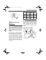
ESU10605
Fuel
EWS00071
WARNING
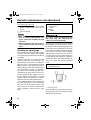
Gasoline and gasoline vapors are extremely flammable. To avoid fires and explosions and to reduce the risk of injury
when refueling, follow these instructions.
Make sure there is sufficient gasoline in the
tank.
1. Before refueling, turn off the engine and
be sure that nobody is on the snowmobile. Never refuel while smoking, or while
in the vicinity of sparks, open flames, or
other sources of ignition such as the pilot
lights of water heaters and clothes dryers.
2. Do not overfill the fuel tank. Stop filling
when the fuel reaches the bottom of the
filler tube. Because fuel expands when it
heats up, heat from the engine or the sun
can cause fuel to spill out of the fuel tank.
1. Filler tube
2. Maximum fuel level
3.
4.
Wipe up any spilled fuel immediately.
Be sure the fuel tank cap is closed securely by turning it clockwise.
EWS00680
WARNING
Gasoline is poisonous and can cause injury or death. Handle gasoline with care.
Never siphon gasoline by mouth. If you
should swallow some gasoline or inhale a
lot of gasoline vapor, or get some gasoline
in your eyes, see your doctor immediately.
If gasoline spills on your skin, wash with
soap and water. If gasoline spills on your
clothing, change your clothes.
37
U8HV10E0.book Page 38 Monday, May 16, 2011 1:15 PM
Control functions
Recommended fuel:
REGULAR UNLEADED GASOLINE
ONLY
Fuel tank capacity:
RS90P 34.6 L (9.14 US gal,
7.61 Imp.gal)
RS90PLT 34.6 L (9.14 US gal,
7.61 Imp.gal)
RST90 39.3 L (10.38 US gal,
8.65 Imp.gal)
RST90PGT 34.6 L (9.14 US gal,
7.61 Imp.gal)
Your Yamaha engine has been designed to
use regular unleaded gasoline with a pump
octane number [(R+M)/2] of 86 or higher, or a
research octane number of 91 or higher.
ECS00084
NOTICE
●
●
●
●
Oxygenated fuels (gasohol) containing
a maximum 10% of ethanol (E10) can be
used, although richer jetting may be required to prevent engine damage. Consult a Yamaha dealer. Gasohol
containing methanol is not recommended.
Make sure that snow or ice does not enter the fuel tank when refueling.
Do not use alcohol deicers or water absorbing additives with oxygenated fuel.
The fuel tank should be filled with the
recommended gasoline. The use of other gasoline will cause severe damage to
internal engine parts, such as the valves
and piston rings, as well as to the exhaust system.
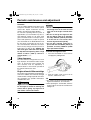
ESU14001
Suspension
The suspension can be adjusted to suit rider
preference. Softer settings, for example, may
provide greater rider comfort, while harder
settings may allow more precise handling and
control over certain types of terrain or riding
conditions.
38
If you are not familiar with suspension adjustments, have a Yamaha dealer make these
adjustments.
EWS00151
WARNING
Read and understand the following information before handling shock absorbers
that contain highly pressurized nitrogen
gas.
● Do not tamper with or attempt to open
the cylinder assemblies.
● Do not subject the shock absorbers to
an open flame or other high heat source.
This may cause the unit to explode due
to excessive gas pressure.
● Do not deform or damage the cylinders
in any way. Cylinder damage will result
in poor damping performance.
● Do not dispose of a damaged or worn
out shock absorber yourself. Take the
shock absorber to a Yamaha dealer for
any service.
TIP
Use the special wrench included in the owner’s tool kit to make the suspension adjustments. If the tool kit for your model does not
include the special wrench, the special
wrench can be obtained at a Yamaha dealer.
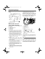
ESU10894
Adjusting the spring preload of the
front shock absorbers
EWS00720
WARNING
The spring preload of the left and right
shock absorbers must be adjusted to the
same setting. Uneven settings can cause
poor handling and loss of stability.
The spring preload can be adjusted by turning
the adjusting nuts.
Adjust the spring preload as follows.
U8HV10E0.book Page 39 Monday, May 16, 2011 1:15 PM
Control functions
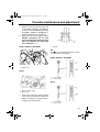
1.
2.
Loosen the locknut.
To increase the spring preload and thereby harden the suspension, turn the adjusting nut in direction (a). To decrease
the spring preload and thereby soften the
suspension, turn the adjusting nut in direction (b).
3
1
3.
Tighten the locknut to the specified
torque. NOTICE: Always tighten the
locknut against the adjusting nut, and
then tighten the locknut to the specified torque. [ECS00860]
Tightening torque:
Locknut:
42 Nm (4.2 m·kgf, 30 ft·lbf)
(a)
ESU13134
2
(b)
1. Locknut
2. Distance A
3. Spring preload adjusting nut
TIP
The spring preload setting is determined by
measuring distance A, shown in the illustration. The longer distance A is, the higher the
spring preload; the shorter distance A is, the
lower the spring preload.
Spring preload setting*:
Minimum (soft):
RS90P / RS90PLT 122.5 mm (4.82
in)
RST90 161.0 mm (6.34 in)
RST90PGT 122.5 mm (4.82 in)
Standard:
RS90P / RS90PLT 129.5 mm (5.10
in)
RST90 162.0 mm (6.38 in)
RST90PGT 122.5 mm (4.82 in)
Maximum (hard):
RS90P / RS90PLT139.5 mm (5.49
in)
RST90 172.0 mm (6.77 in)
RST90PGT 132.5 mm (5.22 in)
* Distance A changes 1.5 mm (0.06 in)
with each full turn of the adjusting nut.
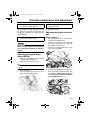
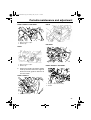
Adjusting the spring preload of the
center shock absorber and the rear
torsion springs (RST90 / RST90PGT)
The spring preload can be adjusted by turning
the adjusting nut on the center shock absorber and the adjusters on the rear torsion
springs. Adjust the spring preload as follows.
Center shock absorber
1. Loosen the locknut.
2. To increase the spring preload and thereby harden the suspension, turn the adjusting nut in direction (a). To decrease
the spring preload and thereby soften the
suspension, turn the adjusting nut in direction (b).
1
2
3
(a)
(b)
1. Spring preload adjusting nut
2. Distance A
3. Locknut
39
U8HV10E0.book Page 40 Monday, May 16, 2011 1:15 PM
Control functions
TIP
The spring preload setting is determined by
measuring distance A, shown in the illustration. The longer distance A is, the higher the
spring preload; the shorter distance A is, the
lower the spring preload.
Spring preload setting*:
Minimum (soft):
RST90 111.5 mm (4.39 in)
RST90PGT 122.1 mm (4.81 in)
Standard:
RST90 112.5 mm (4.43 in)
RST90PGT 122.1 mm (4.81 in)
Maximum (hard):
RST90 122.5 mm (4.82 in)
RST90PGT 132.1 mm (5.20 in)
* Distance A changes 1.5 mm (0.06 in)
with each full turn of the adjusting nut.
3.
Tighten the locknut to the specified
torque. NOTICE: Always tighten the
locknut against the adjusting nut, and
then tighten the locknut to the specified torque. [ECS00860]
Tightening torque:
Locknut:
42 Nm (4.2 m·kgf, 30 ft·lbf)
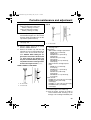
Rear torsion springs
EWS00750
WARNING
The left and right spring preloads must be
adjusted to the same setting. Uneven settings can cause poor handling and loss of
stability.
To increase the spring preload and thereby
harden the suspension, turn the adjuster in direction (a). To decrease the spring preload
and thereby soften the suspension, turn the
adjuster in direction (b).
40
(a)
(b)
1
1. Spring preload adjuster
Spring preload setting:
Minimum (soft):
S
Standard:
M
Maximum (hard):
H
ESU14300
Adjusting the spring preload of the
rear shock absorber (RS90P /
RS90PLT)
The spring preload can be adjusted by turning
the adjusting nut on the rear shock absorber.
Adjust the spring preload as follows.
1. Loosen the locknut.
2. To increase the spring preload and thereby harden the suspension, turn the adjusting nut in direction (a). To decrease
the spring preload and thereby soften the
suspension, turn the adjusting nut in direction (b).
U8HV10E0.book Page 41 Monday, May 16, 2011 1:15 PM
Control functions
ESU13094
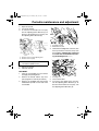
Adjusting the 2-up adjusting blocks
(RST90)
(a)
EWS00760
WARNING
1
3
(b)
2
1. Spring preload adjusting nut
2. Distance A
3. Locknut
Make sure that the 2-up adjusting blocks
are installed in the same position on both
sides of the snowmobile, otherwise poor
handling and loss of stability may result.
The spring force can be adjusted by changing
the position of the 2-up adjusting blocks.
TIP
The spring preload setting is determined by
measuring distance A, shown in the illustration. The longer distance A is, the higher the
spring preload; the shorter distance A is, the
lower the spring preload.
Spring preload setting*:
Minimum (soft):
147.5 mm (5.81 in)
Standard:
157.5 mm (6.20 in)
Maximum (hard):
182.0 mm (7.17 in)
* Distance A changes 1.5 mm (0.06 in)
with each full turn of the adjusting nut.
3.
Tighten the locknut to the specified
torque. NOTICE: Always tighten the
locknut against the adjusting nut, and
then tighten the locknut to the specified torque. [ECS00860]
1. 2-up adjusting block
TIP
●
●
1.
Be sure to make this adjustment when
there is no load (rider or cargo) on the
snowmobile.
Use the special tools included in the owner’s tool kit to make the adjustment.
Insert the special tools into the 2-up adjusting block as shown.
Tightening torque:
Locknut:
42 Nm (4.2 m·kgf, 30 ft·lbf)
41
U8HV10E0.book Page 42 Monday, May 16, 2011 1:15 PM
Control functions
(b)
(a)
1
1.
2.
3.
4.
2.
3.
4.
2-up position (rider and passenger)
Solo rider position
Special tool
Lock pin
Pull the lock pin and turn the special tools
to change the block position.
Release the lock pin.
Remove the special tools from the 2-up
adjusting block.
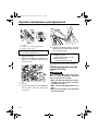
1. Compression damping force adjusting knob
Compression damping force setting:
Minimum (soft):
12 click(s) in direction (b)*
Standard:
6 click(s) in direction (b)*
Maximum (hard):
2 click(s) in direction (b)*
* With the adjusting knob fully turned in
direction (a)
ESU14310
Adjusting the damping force of the
rear shock absorber (RS90P /
RS90PLT / RST90PGT)
RST90PGT
The compression damping force can be adjusted by turning the adjusting knob.
To increase the compression damping force,
turn the adjusting knob in direction (a). To decrease the compression damping force, turn
the adjusting knob in direction (b). NOTICE:
Do not continue to turn the adjusting knob
in direction (a) after it stops. The shock absorber could be damaged and damping
force adjustments will not be able to be
made. Do not turn the adjusting knob in direction (b) more than 12 click(s). Even if
the adjusting knob is continually turned
after 12 click(s), there will be no change in
the damping force. Be sure to stop the adjusting knob at a position where there is a
click. [ECS00910]
42
RS90P / RS90PLT
The rebound damping force can be adjusted
by turning the adjusting knob.
To increase the rebound damping force, turn
the adjusting knob in direction (a). To decrease the rebound damping force, turn the
adjusting knob in direction (b). NOTICE: Do
not continue to turn the adjusting knob in
direction (a) after it stops. The shock absorber could be damaged and damping
force adjustments will not be able to be
made. Do not turn the adjusting knob in direction (b) more than 20 click(s). Even if
the adjusting knob is continually turned
after 20 click(s), there will be no change in
the damping force. Be sure to stop the adjusting knob at a position where there is a
click. [ECS01060]
U8HV10E0.book Page 43 Monday, May 16, 2011 1:15 PM
Control functions
1
3
Min
4
Max
(b)
(a)
2
1
1. Rebound damping force adjusting knob
Rebound damping force setting:
Minimum (soft):
20 click(s) in direction (b)*
Standard:
11 click(s) in direction (b)*
Maximum (hard):
3 click(s) in direction (b)*
* With the adjusting knob fully turned in
direction (a)
1.
2.
3.
4.
5.
5
Special wrench corner
Control rod adjuster
Scale range
Special wrench
Control rod length
TIP
Use the special wrench in the owner’s tool kit
to make this adjustment.
2.
3.
ESU11047
Adjusting the control rods
The weight transfer can be adjusted by turning the adjuster on the control rod (RS90P /
RS90PLT) or the adjusting nuts on the control
rods (RST90 / RST90PGT).
RS90P / RS90PLT
1. Check the control rod length using the
scale on the special wrench as shown.
Loosen the locknut.
To increase weight transfer, turn the adjuster in direction (a), and to decrease
weight transfer, turn it in direction (b).
WARNING! Never adjust the control
rod beyond the range of the scale on
the special wrench, otherwise the control rod could be damaged, which
could lead to an accident or injury.
[EWS00181]
TIP
In order to obtain a precise measurement, the
special wrench corner should touch the control rod adjuster, and the locknut must be
turned so that one of its notches aligns with
the wrench allowing the wrench to fit horizontally on the control rod.
1. Locknut
2. Control rod adjuster
4.
Tighten the locknut while holding the adjuster in place.
43
U8HV10E0.book Page 44 Monday, May 16, 2011 1:15 PM
Control functions
TIP
(b) 1
Make sure that the special wrench is securely
fitted on the locknut.
2
1
(a)
1. Special wrench
Locknut tightening torque:
35 Nm (3.5 m·kgf, 25 ft·lbf)
RST90 / RST90PGT
EWS00770
WARNING
The left and right adjusting nuts must be
set to the same position. Uneven settings
can cause poor handling and loss of stability.
1.
44
Loosen the locknut while holding the adjusting nut.
1. Locknut
2. Control rod adjusting nut
2.
To increase weight transfer, turn the adjusting nut in direction (a), and to decrease weight transfer, turn it in direction
(b). WARNING! Never adjust the control rods beyond the maximum setting, indicated by red paint; otherwise,
they could be damaged, which could
lead to an accident or injury. [EWS00173]
U8HV10E0.book Page 45 Monday, May 16, 2011 1:15 PM
Control functions
1
2
3
5
1.
2.
3.
4.
5.
3.
4
Locknut
Control rod adjusting nut
Standard position
Adjustable range
Red paint area
Tighten the locknut while holding the adjusting nut in place. NOTICE: Always
tighten the locknut against the adjusting nut, and then tighten the locknut to
the specified torque. [ECS00860]
Locknut tightening torque:
25 Nm (2.5 m·kgf, 18 ft·lbf)
45
U8HV10E0.book Page 46 Monday, May 16, 2011 1:15 PM
Pre-operation checks
ESU11071
Inspect your vehicle each time you use it to make sure the vehicle is in safe operating condition.
Always follow the inspection and maintenance procedures and schedules described in the
Owner’s Manual.
EWS00191
WARNING
Failure to inspect or maintain the vehicle properly increases the possibility of an accident or equipment damage. Do not operate the vehicle if you find any problem. If a problem cannot be corrected by the procedures provided in this manual, have the vehicle
inspected by a Yamaha dealer.
ESU11081
Pre-operation check list
ITEM
CHECKS
PAGE
Fuel
• Check fuel level.
• Refuel if necessary.
• Check fuel line for leakage.
37
Engine oil
• Check oil level in engine.
• If necessary, add recommended oil to specified
level.
• Check vehicle for oil leakage.
78
Coolant
• Check coolant level.
• Add if necessary.
84
V-belt
• Check for wear and damage.
• Replace if necessary.
88
Drive guard
• Make sure the drive guard is installed securely.
• Check the drive guard mounts for damage.
28
Brake
• Check operation.
• If soft or spongy, have Yamaha dealer bleed hydraulic system.
• Check brake pads for wear.
• Replace if necessary.
• Check fluid level in master cylinder.
• If necessary, add recommended brake fluid to
specified level.
• Check hydraulic system for leakage.
93
Air filter
• Check that there is no snow under the air filter element.
• If necessary, brush off the snow.
73
Tool kit and recommended
equipment
• Check for proper placement.
Shroud and covers
• Make sure that the shroud and covers are securely
fastened.
63
Skis and ski runners
• Check for wear and damage.
• If necessary, have Yamaha dealer replace skis or
ski runners.
96
46
62, 63
U8HV10E0.book Page 47 Monday, May 16, 2011 1:15 PM
Pre-operation checks
ITEM
CHECKS
PAGE
Check the deflection.
Adjust if necessary.
Check for wear and damage.
If necessary, have a Yamaha dealer replace track.
98
Drive track
•
•
•
•
Slide runners
• Check for wear and damage.
• If necessary, have Yamaha dealer replace slide
runners.
Steering
• Check for excessive free play.
Lights, signals and switches
• Check operation.
• Correct if necessary.
Throttle lever
• Make sure that operation is smooth and spring
back to its original position when released.
12
Throttle override system
(T.O.R.S.)
• Check the T.O.R.S. for proper operation.
• If system is not functioning properly, have Yamaha
dealer check vehicle.
72
98
97
24, 24, 104,
107
47
U8HV10E0.book Page 48 Monday, May 16, 2011 1:15 PM
Operation
ESU13500
Read the Owner’s Manual carefully to become familiar with all controls. If there is a
control or function you do not understand, ask
your Yamaha dealer.
EWS00201
WARNING
Failure to familiarize yourself with the controls can lead to loss of control, which
could cause an accident or injury.
2.
ESU13212
TIP
This model is equipped with:
● RS90P / RS90PLT / RST90PGT: an engine oil pressure switch to stop the engine
in case an engine oil pressure drop is detected. To start the engine after this system
has stopped the engine, be sure to place
the snowmobile on a level surface, and
then turn the key in the main switch to the
off position, and then to the on position.
Failing to do so will prevent the engine from
starting even though the engine will crank
when turning the key to the start position. If
the engine does not start or if it stops again,
ask a Yamaha dealer to inspect the snowmobile.
● an engine overheating prevention system,
which prevents overheating when the engine is idling. When the engine has been
idling for 3 minutes or longer and the coolant temperature has risen above 100 °C
(212 °F), the engine automatically stops to
prevent overheating. The engine can be
started after it stops.
ESU13970
Starting the engine
RS90P / RS90PLT / RST90PGT
1.
48
Apply the parking brake.
Be sure the engine stop switch is in the
run position. The starter motor cannot be
operated when the engine stop switch is
in the off position.
1
2
1. Run position
2. Off position
3.
Turn the main switch to the start position
and release it when the engine starts.
NOTICE: Release the switch immediately after the engine starts. If the engine fails to start, release the switch,
wait a few seconds, then try again.
Each attempt should be as short as
possible to preserve the battery. Do
not crank the engine more than 10
seconds on any one attempt. [ECS00331]
U8HV10E0.book Page 49 Monday, May 16, 2011 1:15 PM
Operation
1
2
1
1. Start
4.
5.
Warm up the engine until it runs smoothly.
Be sure the low coolant temperature indicator light has gone out before operation.
(See page 18 for detailed information
about the indicator light.)
1. Run position
2. Off position
3.
Fully open the starter (choke) lever.
RST90
1.
Apply the parking brake.
1.
2.
3.
4.
Starter (choke) lever
Fully open position (cold engine starting)
Half-open position (warming engine up)
Closed position (warm engine starting)
TIP
2.
Be sure the engine stop switch is in the
run position. The starter motor cannot be
operated when the engine stop switch is
in the off position.
The starter (choke) lever is not required when
the engine is warm. Move the starter (choke)
lever to the closed position.
4.
Turn the main switch to the start position
and release it when the engine starts.
NOTICE: Release the switch immediately after the engine starts. If the engine fails to start, release the switch,
wait a few seconds, then try again.
Each attempt should be as short as
possible to preserve the battery. Do
not crank the engine more than 10
seconds on any one attempt. [ECS00331]
49
U8HV10E0.book Page 50 Monday, May 16, 2011 1:15 PM
Operation
ECS00340
1
NOTICE
●
●
1. Start
5.
6.
Warm up the engine, and then close the
starter (choke) lever when the engine
runs smoothly.
Be sure the low coolant temperature indicator light has gone out before operation.
(See page 18 for detailed information
about the indicator light.)
ESU11310
Break-in
There is never a more important period in the
life of your engine than the period between 0
and 500 km (300 mi). For this reason, you
should read the following material carefully.
Since the engine is brand new, do not put an
excessive load on it for the first 500 km (300
mi). The various parts in the engine wear and
polish themselves to the correct operating
clearances. During this period, prolonged fullthrottle operation or any condition that might
result in engine overheating must be avoided.
Operating your snowmobile for the
first time
Start the engine and let it idle for 15 minutes.
0–160 km (0–100 mi)
Avoid prolonged operation above 6000 r/min.
160–500 km (100–300 mi)
Avoid prolonged operation above 8000 r/min.
500 km (300 mi) and beyond
The snowmobile can now be operated normally.
50
After 800 km (500 mi) of operation, the
engine oil must be changed and the oil
filter cartridge replaced.
If any engine trouble should occur during the engine break-in period, immediately have a Yamaha dealer check the
snowmobile.
ESU11333
Riding your snowmobile
Getting to know your snowmobile
EWS00211
WARNING
To avoid severe injury or death:
● Keep both hands on the handlebar during operation.
● Never put your feet outside the running
boards.
● Avoid higher speeds or more difficult
maneuvers until you have become thoroughly familiar with your snowmobile
and all of its controls.
A snowmobile is a rider active vehicle, and
your riding position and your balance are the
two basic factors of maneuvering your snowmobile.
Riding your snowmobile requires skills acquired through practice over a period of time.
Take the time to learn the basic techniques
well before attempting more difficult maneuvers.
Riding your new snowmobile can be a very
enjoyable activity, providing you with hours of
pleasure. However, it is essential to familiarize yourself with the operation of the snowmobile to achieve the skill necessary to enjoy
riding safely. Before operating the snowmobile, read this Owner’s Manual completely
and understand the operation of the controls.
U8HV10E0.book Page 51 Monday, May 16, 2011 1:15 PM
Operation
Pay particular attention to the safety information on page 6.
Please read all warning and notice labels on
your snowmobile. Also, read the Snowmobiler’s Safety Handbook that is supplied with
your snowmobile.
Learning to ride your snowmobile
Before you ride, always perform the pre-operation checks listed on page 46. The short time
spent checking the condition of the snowmobile will be rewarded with added safety and a
more reliable snowmobile. Always wear the
proper clothing for both warmth and to help
protect you from injury if an accident occurs.
Become familiar with operating your snowmobile at low speeds, even if you are an experienced rider. Do not attempt to operate at
maximum performance until you are totally familiar with the snowmobile’s handling and
performance characteristics.
The beginning operator should select a large
flat area to become familiar with the snowmobile. Make sure that this area is free of obstacles and other traffic. You should practice
control of the throttle and brake, and master
turning techniques in this area before trying
more difficult terrain.
Set the parking brake and follow the instructions on page 48 to start the engine. Once the
engine has warmed up, you are ready to begin riding your snowmobile.
A broken track, track fittings, or debris
thrown by the track could be dangerous to bystanders. [EWS00690]
Braking
EWS00220
WARNING
●
●
Many surfaces such as ice and hardpacked snow require much longer stopping distances. Be alert, plan ahead, and
begin decelerating early.
Improper use of the brake can cause the
drive track to lose traction, reduce control, and increase the possibility of an
accident.
When slowing down or stopping, release the
throttle and apply the brake gently—not suddenly.
Turning
For most snow surfaces, “body English” is the
key to turning.
As you approach a curve, slow down and begin to turn the handlebar in the desired direction. As you do so, put your weight on the
running board to the inside of the turn and
lean your upper body into the turn.
To start out and accelerate
1.
2.
With the engine idling, release the parking brake.
Apply the throttle slowly and smoothly.
The V-belt clutch will engage and you will
start to accelerate. WARNING! Do not
allow anyone to stand behind the
snowmobile when starting the engine.
This procedure should be practiced at low
speeds many times, in a large flat area with no
obstacles. Once you have learned this technique, you should be able to perform it at high-
51
U8HV10E0.book Page 52 Monday, May 16, 2011 1:15 PM
Operation
er speeds or in tighter curves. Lean more as
the turn gets sharper or is made at higher
speeds.
Improper riding techniques such as abrupt
throttle changes, excessive braking, incorrect
body movements, or too much speed for the
sharpness of the turn may cause the snowmobile to tip.
If your snowmobile begins to tip while turning,
lean more into the turn to regain balance. If
necessary, gradually let off on the throttle or
steer to the outside of the turn.
Remember:
Avoid higher speeds until you are thoroughly
familiar with the operation of your snowmobile.
Riding uphill
EWS00231
WARNING
Operation on slopes can lead to loss of
control if proper techniques are not used.
Follow these instructions to reduce your
risk of an accident. Do not try steeper or
more difficult inclines until you have developed your skill on gentle slopes.
You should practice first on gentle slopes. Try
more difficult climbs only after you have developed your skill. As you approach a hill, accelerate before you start the climb, and then
reduce the throttle to prevent track slippage. It
is also important to keep your weight on the
uphill side at all times. On climbs straight up
the hill, this can be accomplished by leaning
forward and, on steeper inclines, standing on
the running boards and leaning forward over
the handlebar. (Also see “Traversing a
slope”.)
52
Slow down as you reach the crest of the hill,
and be prepared to react to obstacles, sharp
drops, or other vehicles or people which may
be on the other side. If you are unable to continue up a hill, do not spin the track. Stop the
engine and set the parking brake. Then pull
the rear of the snowmobile around to point the
snowmobile back down the hill. When the
snowmobile is pointed downhill, mount your
snowmobile from the uphill side. Restart the
engine, release the parking brake, and descend the hill.
Riding downhill
EWS00240
WARNING
Use extra caution when applying the brake
during a descent. Excessive braking will
cause the drive track to lock, causing a
loss of control.
When riding downhill, keep speed to a minimum. It is important to apply just enough
throttle to keep the clutch engaged while descending the hill. This will allow you to use engine compression to help slow the
snowmobile, and to keep the snowmobile
from rolling freely down the hill. Also apply the
brake frequently, with light pressure.
U8HV10E0.book Page 53 Monday, May 16, 2011 1:15 PM
Operation
Traversing a slope
EWS00251
WARNING
Driving across the face of a slope (“sidehilling”) can lead to overturn or loss of
control if proper techniques are not used.
Follow these instructions to reduce your
risk of an accident. Do not try steeper or
more difficult inclines until you have developed your skill on gentle slopes.
Traversing a slope requires you to properly
position your weight to maintain proper balance. As you travel across the slope, lean
your body to position your weight towards the
uphill side. A recommended riding position is
to kneel with the knee of your downhill leg on
the seat and the foot of your uphill leg on the
running board. This position will make it easier for you to shift your body weight as needed.
Snow and ice are slippery, so be prepared for
the possibility that your snowmobile could begin to slip sideways on the slope. If this happens, steer in the direction of the slide if there
are no obstacles in your path. As you regain
proper balance, gradually steer again in the
direction you wish to travel.
If your snowmobile starts to tip, steer down
the hill to regain balance. WARNING! If you
are unable to maintain correct balance,
and your snowmobile is going to tip over,
dismount your snowmobile immediately
on the uphill side to avoid being hit or
caught under the snowmobile as it tips
over. [EWS00261]
Ice or icy surface
EWS00270
WARNING
When you have to operate on ice or icy
surfaces, drive slowly and cautiously.
Avoid accelerating, turning, and braking
rapidly. Steering is minimal and uncontrolled spins are an ever-present danger.
Operating on ice or icy surfaces can be very
dangerous. Traction for turning, stopping, and
starting is much less than that on snow.
Hard-packed snow
It can be more difficult to negotiate on hardpacked snow as both the skis and drive track
do not have as much traction as when the
snowmobile is operated on fresh snow. Avoid
rapid acceleration, turning, and braking.
Operation on surfaces other than
snow or ice
Operation of your snowmobile on surfaces
other than snow or ice should be avoided. Operation under such conditions will damage or
result in rapid wear of the ski runners, drive
53
U8HV10E0.book Page 54 Monday, May 16, 2011 1:15 PM
Operation
track, slide runners, and drive sprockets. Operation of the snowmobile on the following
surfaces should be avoided at all times:
● Dirt
● Sand
● Rocks
● Grass
● Bare pavement
Other surfaces that should be avoided for the
sake of drive track and slide runner life are:
● Glare ice surfaces
● Snow mixed with a lot of dirt and sand
All of the above surfaces have one thing in
common in regard to drive track and slide runners: little or no lubricating ability. Drive track
and all slide rail systems require lubrication
(snow or water) between the slide runners
and the slide metal. In the absence of lubrication, the slide runners will rapidly wear and in
severe cases, literally melt away, and the
drive track will be subject to damage or failure.
Also traction aids such as studs, cleats, etc.,
may cause further track damage or failure.
EWS00280
WARNING
Drive track damage or failure could result
in loss of braking ability and snowmobile
control, which could cause an accident.
● Always check the drive track for damage
or maladjustment before operating the
snowmobile.
● Do not operate the snowmobile if you
find damage to the drive track.
ECS00350
NOTICE
Ride on fresh snow frequently. Operating
on ice or hard-packed snow will rapidly
wear the slide runners.
54
ESU11350
Maximizing drive track life
Recommendations
Track tension
During initial break-in, the new drive track will
tend to stretch quickly as the track settles. Be
sure to correct the track tension and alignment frequently. (See page 98 for adjustment
procedures.) A loose track can slip (ratchet),
derail or catch on suspension parts causing
severe damage. Do not overtighten the drive
track, otherwise it may increase the friction
between the track and the slide runners, resulting in the rapid wear of both components.
Also, this may put an excessive load on the
suspension components, resulting in component failure.
Marginal snow
The drive track and the slide runners are lubricated and cooled by snow and water. To prevent the drive track and slide runners from
overheating, avoid sustained high-speed usage in areas such as icy trails, frozen lakes
and rivers that have minimal snow coverage.
An overheated track will be weakened internally, which may cause failure or damage.
Off-trail riding
Avoid off-trail riding until there is sufficient
snow coverage. It generally takes several feet
of snow to provide a good overall base to
properly cover debris, such as rocks, logs,
etc. If snow coverage is not sufficient, stay on
trails to avoid impact damage to the drive
track.
Studded track
In general, track life will be shortened when
studs are installed. Drilling stud holes into the
drive track will cut the internal fibers, which
weakens the track. Avoid spinning the drive
track. Studs may catch on an object and pull
out of the track, leaving tears and damage
U8HV10E0.book Page 55 Monday, May 16, 2011 1:15 PM
Operation
around the already weakened area. To minimize possible damage, consult your stud
manufacturer for installation and stud pattern
recommendations.
Yamaha does not recommend track studding.
RS90P / RS90PLT / RST90PGT
ESU11395
1
Driving
EWS00300
Be sure to read the “SAFETY INFORMATION” section on page 6 and the “Riding
your snowmobile” section on page 50
carefully before operating the snowmobile.
3
2
WARNING
1. Pull out.
2. Slide to “REV” (reverse).
3. Release.
EWS00310
WARNING
●
●
●
●
Make sure that the throttle lever is fully
released and the snowmobile is at a full
stop before shifting.
Be sure to slide the shift lever to “FWD”
or “REV” until it stops completely and
only while the engine is idling.
Make sure that the area behind the
snowmobile is clear before reversing.
Watch behind.
Reduce speed and avoid sharp turning
when operating the snowmobile in reverse.
3
2
1
1. Pull out.
2. Slide to “REV” (reverse).
3. Release.
RST90
TIP
Make sure that the engine is warmed up
enough before riding.
1.
To select the desired operating position,
pull the shift lever out, slide it to “FWD” or
to “REV” until it stops, and then release it.
NOTICE: Do not shift from “FWD” to
“REV” or from “REV” to “FWD” while
the snowmobile is moving, as the
drive train could be damaged. [ECS00811]
1. Pull out.
2. Slide to “FWD” (forward).
3. Release.
55
U8HV10E0.book Page 56 Monday, May 16, 2011 1:15 PM
Operation
1
1. Pull out.
2. Slide to “REV” (reverse).
3. Release.
TIP
1. Off
●
Push down the engine stop switch to stop
the engine in an emergency.
The reverse buzzer beeps while the shift lever
is in reverse.
2.
While squeezing the brake lever, release
the parking brake by moving the parking
brake lever to the right, and then release
the brake lever.
ESU13780
Transporting
3.
Squeeze the throttle lever slowly to start
out.
Turn the handlebar in the desired direction.
Squeeze the brake lever to stop the
snowmobile.
Apply the parking brake by moving the
parking brake lever to the left.
4.
5.
6.
ESU11411
Stopping the engine
●
Turn the main switch to the off position to
stop the engine.
56
When transporting your snowmobile on a trailer or in a truck, observe the following recommendations to help protect it from damage:
● RST90: Make sure that the fuel level in the
fuel tank is lower than the bottom of the carburetors. Otherwise, the vibration and
bumps from the road surface could make it
possible for fuel to flow through the carburetors into the cylinders. This can result in
“hydrostatic lock,” a condition where the engine cannot rotate because of fuel accumulated in the engine. Severe engine damage
can result from hydrostatic lock. When possible, the fuel tank should be empty during
transportation, especially if the trip takes
longer than 30 minutes.
U8HV10E0.book Page 57 Monday, May 16, 2011 1:15 PM
Operation
●
●
If transporting the snowmobile in an open
trailer or truck, put a tight fitting cover on the
snowmobile. A cover specifically designed
for your snowmobile is best. This will help
keep foreign objects out of the cooling
vents, and also help protect the snowmobile against damage from debris on the
road.
If transporting the snowmobile in an open
trailer or truck in areas where road salt is
used, coat metal suspension surfaces lightly with oil or another protectant. This will
help protect against corrosion. Be sure to
clean the snowmobile when you get to your
destination to remove any corrosive salts.
57
U8HV10E0.book Page 58 Monday, May 16, 2011 1:15 PM
Periodic maintenance and adjustment
ESU11452
Periodic inspection, adjustment, and lubrication will keep your snowmobile in the safest and
most efficient condition possible. Safety is an obligation of the vehicle owner/operator. The
most important points of vehicle inspection, adjustment, and lubrication are explained on the
following pages.
EWS00341
WARNING
Failure to properly maintain the snowmobile or performing maintenance activities incorrectly may increase your risk of injury or death during service or while using the snowmobile. If you are not familiar with snowmobile service, have a Yamaha dealer perform
service.
EWS00700
WARNING
Turn off the engine when performing maintenance unless otherwise specified.
● A running engine has moving parts that can catch on body parts or clothing, and electrical parts that can cause shocks or fires.
● Running the engine while servicing can lead to eye injury, burns, fire, or carbon monoxide poisoning–possibly leading to death. See page 6 for more information about
carbon monoxide.
EWS00790
WARNING
Brake discs, calipers, and linings can become very hot during use. To avoid possible
burns, let brake components cool before touching them.
Maintenance, replacement, or repair of the emission control devices and systems may
be performed by any repair establishment or individual that is certified (if applicable).
Proper periodic maintenance of your snowmobile is important in order to enjoy long, pleasurable use. Especially important are the maintenance services related to emission control. These
controls not only function to ensure cleaner air, but are also vital to proper engine operation and
maximum performance. In the following periodic maintenance charts, the services related to
emission control are grouped separately. These services require specialized data, knowledge,
and equipment. Yamaha dealers are trained and equipped to perform these particular services.
58
U8HV10E0.book Page 59 Monday, May 16, 2011 1:15 PM
Periodic maintenance and adjustment
ESU11461
Periodic maintenance chart for the emission control system
Items marked with an asterisk should be performed by a Yamaha dealer as they require special
tools, data and technical skills.
ITEM
REMARKS
INITIAL
EVERY
1 month
or 800 km
(500 mi)
(40 hr)
Seasonally
or
4000 km
(2500 mi)
(200 hr)
PAGE
Spark plugs
• Check condition.
• Adjust gap and clean.
• Replace if necessary.
*
Valve clearance
• Check and adjust valve clearance when engine is cold.
*
Crankcase breather
system
• Check breather hose for cracks
or damage.
• Replace if necessary.
—
*
Fuel filter (RST90)
• Check condition.
• Replace if necessary.
—
*
Fuel line
• Check fuel hose for cracks or
damage.
• Replace if necessary.
—
*
Idle speed (RST90)
• Check and adjust idle speed.
69
*
Fuel injection
(RS90P / RS90PLT /
RST90PGT)
• Check synchronization.
• Adjust if necessary.
—
• Adjust synchronization.
—
*
Carburetors
(RST90)
*
Exhaust system
• Adjust the jets.
• Check for leakage.
• Tighten or replace gasket if
necessary.
68
Every 40000 km (25000
mi)
Whenever operating
condition (elevation/temperature) is changed.
78
77
—
59
U8HV10E0.book Page 60 Monday, May 16, 2011 1:15 PM
Periodic maintenance and adjustment
ESU11564
General maintenance and lubrication chart
ITEM
REMARKS
Engine oil
• Change (warm engine before
draining).
*
Engine oil filter cartridge
• Replace.
*
Cooling system
• Check coolant level.
• Bleed the cooling system if
necessary.
• Check engagement and shift
speed.
• Adjust if necessary.
*
Primary and secondary clutches
*
Drive chain
*
Drive chain oil
*
Brake and parking
brake
EVERY
1 month
or 800 km
(500 mi)
(40 hr)
Seasonally
or
4000 km
(2500 mi)
(200 hr)
PAGE
78
Every
20000 km
(12000 mi)
78
84
—
Whenever operating elevation is changed.
—
• Inspect sheaves for wear and
damage.
• Inspect weights/rollers and
bushings for wear for primary.
• Inspect ramp shoes/bushings
for wear for secondary.
• Replace if necessary.
—
• Lubricate with specified
grease.
—
• Check chain slack.
• Adjust if necessary.
Initial at 500 km (300 mi)
and every 800 km (500
mi) thereafter.
91
• Check oil level.
91
• Change.
91
• Adjust free play and/or replace
pads if necessary.
93
• Change brake fluid.
Control cables
• Make sure that operation is
smooth.
• Lubricate if necessary.
*
Disc brake installation
• Check for slight free play.
• Lubricate shaft with specified
grease as required.
*
Extrovert drive
sprocket (RS90P /
RS90PLT /
RST90PGT)
• Check for wear and damage.
• Replace if necessary.
60
INITIAL
See TIP following this
chart.
93
102
Every 1600 km (1000
mi)
—
95
U8HV10E0.book Page 61 Monday, May 16, 2011 1:15 PM
Periodic maintenance and adjustment
ITEM
REMARKS
INITIAL
EVERY
1 month
or 800 km
(500 mi)
(40 hr)
Seasonally
or
4000 km
(2500 mi)
(200 hr)
PAGE
*
Slide runners
• Check for wear and damage.
• Replace if necessary.
98
*
Skis and ski runners
• Check for wear and damage.
• Replace if necessary.
96
*
Steering system
• Check toe-out.
• Adjust if necessary.
97
*
Steering bearings
• Check bearing assemblies for
looseness.
• Lubricate with specified
grease.
—
*
Skis and front
shock absorbers
• Lubricate with specified
grease.
102
*
Suspension component
• Lubricate with specified
grease.
102
*
Drive track
• Check the deflection.
• Adjust if necessary.
Fittings and fasteners
• Make sure that all nuts, bolts
and screws are properly tightened.
• Tighten if necessary.
108
Battery
• Check condition.
• Charge if necessary.
108
*
Initial at 500 km (300 mi)
and every 800 km (500
mi) thereafter.
98
TIP
Brake system:
● After disassembling the master cylinder or caliper cylinder, always change the brake fluid.
Regularly check the brake fluid level and add fluid if necessary.
● Replace the oil seals of the master cylinder and caliper cylinder every two years.
● Replace the brake hose every four years, or if cracked or damaged.
61
U8HV10E0.book Page 62 Monday, May 16, 2011 1:15 PM
Periodic maintenance and adjustment
ESU14112
Tool kit
RS90P / RS90PLT / RST90
The owner’s tool kit is located in the storage
compartment. (See page 32 for information
on how to access the storage compartment.)
The service information included in this manual and the tools provided in the owner’s tool
kit are intended to assist you in the performance of preventive maintenance and minor
repairs. However, additional tools such as a
torque wrench may be necessary to perform
certain maintenance work correctly.
RS90P / RS90PLT
TIP
If you do not have a torque wrench available
during a service operation requiring one, take
your snowmobile to a Yamaha dealer to
check the torque settings and adjust them if
necessary.
RST90PGT
The owner’s tool kit is located in the storage
pouch. (See page 32 for information on how
to access the storage compartment.)
The service information included in this manual and the tools provided in the owner’s tool
kit are intended to assist you in the performance of preventive maintenance and minor
repairs. However, additional tools such as a
torque wrench may be necessary to perform
certain maintenance work correctly.
1. Tool kit
RST90
1
1. Tool kit
ECS00781
NOTICE
Before starting the engine, make sure that
the tool kit is securely fastened and that
the storage pouch zipper is completely
closed.
1. Tool kit
ECS00360
NOTICE
Before starting the engine, make sure that
the tool kit is properly seated in its holder
and is securely fastened.
62
ECS00940
NOTICE
●
●
Be sure to slide the covers onto the
short end of each hexagon wrench before placing the wrenches in the tool kit.
Securely tie the strap around the tool kit.
U8HV10E0.book Page 63 Monday, May 16, 2011 1:15 PM
Periodic maintenance and adjustment
ESU14143
TIP
If you do not have a torque wrench available
during a service operation requiring one, take
your snowmobile to a Yamaha dealer to
check the torque settings and adjust them if
necessary.
3
EWS00091
WARNING
2
Be sure shroud and covers are secured
before operation. A loose shroud or cover
could move and cause loss of control.
4
Shroud
To remove the shroud
Loosen the fasteners, slowly raise the shroud,
and then unhook the shroud from the shroud
stay.
1
1.
2.
3.
4.
Removing and installing the
shroud and covers (RS90P /
RS90PLT / RST90PGT)
Hexagon wrench cover
Hexagon wrench
Tool kit
Strap
1
2
ESU14230
Recommended equipment
It is good practice to carry the spare parts and
other necessary equipment with you while
riding the snowmobile so that minor repairs
can be done if necessary. The following
should be carried at all times:
● Flashlight
● Roll of plastic tape
● Steel wire
● Tow rope
● V-belt
● Light bulbs
When you start out for a long distance trip, extra fuel should be carried as well.
3
1. Fastener
2. Shroud
3. Shroud stay
To install the shroud
Hook the end of the shroud onto the shroud
stay, slowly lower it to the original position,
and then tighten the fasteners.
63
U8HV10E0.book Page 64 Monday, May 16, 2011 1:15 PM
Periodic maintenance and adjustment
1. Shroud stay
2.
Fit the projections on the side cover into
the slots as shown.
3.
4.
Tighten the fasteners.
Install the shroud.
Left and right side covers
To remove a side cover
1. Remove the shroud. (See the above procedure.)
2. Loosen the fasteners, pull outward on the
areas shown, and then slide the side cover forward to remove it.
1
2
Top cover (RS90P / RS90PLT)
1. Fastener
2. Left side cover
To remove the top cover
1. Remove the shroud and the left side cover. (See the above procedures.)
2. Disconnect the auxiliary DC jack coupler.
To install a side cover
1. Fit the projection on the rear of the side
cover into the hole in the fuel tank cover.
1
1. Auxiliary DC jack coupler
64
U8HV10E0.book Page 65 Monday, May 16, 2011 1:15 PM
Periodic maintenance and adjustment
3.
Remove the screws, and then remove
the cable guide.
2
To install the top cover
1. Connect the main switch coupler.
2. Place the top cover in the original position, making sure to fit the projections on
the cover into the slots in the headlight
unit.
1
1
1. Screw
2. Cable guide
4.
Loosen the quick fastener screws.
1. Top cover
3.
4.
Tighten the quick fastener screws.
Pass the brake hose, throttle cable, parking brake cable and wire harness through
the cable guide, place the cable guide in
the original position, and then install the
screws.
1
1. Quick fastener screw
2. Top cover
5.
Lift up the rear of the top cover, disconnect the main switch coupler, and then
remove the cover.
1
1. Cable guide
5.
6.
Connect the auxiliary DC jack coupler.
Install the left side cover and the shroud.
ECS00372
NOTICE
2
1. Top cover
2. Main switch coupler
●
Make sure that all cables, hoses and
leads are routed properly before installing the shroud and covers.
65
U8HV10E0.book Page 66 Monday, May 16, 2011 1:15 PM
Periodic maintenance and adjustment
When installing the shroud and covers,
be sure to tighten the fasteners securely.
●
Top cover (RST90PGT)
To remove the top cover
1. Remove the shroud and the left side cover. (See the above procedures.)
2. Disconnect the auxiliary DC jack coupler.
1
1. Windshield stay rubber cover
5.
6.
Loosen the quick fastener screws.
Lift up the rear of the top cover, disconnect the main switch coupler, and then
remove the cover.
1
1
1. Auxiliary DC jack coupler
3.
Remove the screws, and then remove
the cable guide.
2
1
1. Screw
2. Cable guide
4.
66
Pull the windshield stay rubber covers
upward.
2
1. Top cover
2. Main switch coupler
To install the top cover
1. Connect the main switch coupler.
2. Place the top cover in the original position, making sure to fit the projections on
the cover into the slots in the headlight
unit.
U8HV10E0.book Page 67 Monday, May 16, 2011 1:15 PM
Periodic maintenance and adjustment
Shroud
To open the shroud
Unhook the shroud latches, and then slowly
raise the shroud forward until it stops.
1
2
3.
4.
5.
6.
7.
Tighten the quick fastener screws.
Place the windshield stay rubber covers
in their original position.
Pass the brake hose, throttle cable, parking brake cable and wire harness through
the cable guide, place the cable guide in
the original position, and then install the
screws.
Connect the auxiliary DC jack coupler.
Install the left side cover and the shroud.
ECS00372
NOTICE
●
●
Make sure that all cables, hoses and
leads are routed properly before installing the shroud and covers.
When installing the shroud and covers,
be sure to tighten the fasteners securely.
1. Shroud latch
2. Shroud
To close the shroud
Slowly lower the shroud to its original position,
and then hook the shroud latches.
Right side cover
To remove the right side cover
1. Open the shroud. (See the above procedure.)
2. Remove the screws and bolts, and then
remove the right side cover.
3
ESU13962
Opening and closing the
shroud and removing and installing the right side cover
(RST90)
EWS00810
WARNING
Be sure the shroud and right side cover
are secured before operation. A loose
shroud or cover could move and cause
loss of control.
1
2
1
1. Screw
2. Bolt
3. Right side cover
67
U8HV10E0.book Page 68 Monday, May 16, 2011 1:15 PM
Periodic maintenance and adjustment
To install the right side cover
1. Place the right side cover in the original
position, and then tighten the bolts and
screws.
2. Close the shroud.
Specified spark plug:
Manufacturer:
NGK
Model:
CR8E
ECS01040
NOTICE
●
●
Make sure that all cables, leads, and
hoses are routed properly before closing the shroud and installing the right
side cover.
When installing the right side cover, be
sure to tighten the bolts and screws securely.
ESU11784
Checking the spark plugs
The spark plugs are important engine components and are easy to inspect. The condition
of the spark plugs can indicate the condition of
the engine.
Check the coloration on the white porcelain
insulator around the center electrode. The
ideal coloration at this point is a medium-tolight tan color for a snowmobile that is being
ridden normally. If any spark plug shows a
distinctly different color, there could be something wrong with the engine. For example, a
very white center electrode porcelain color
could indicate an intake track air leak or carburetion problem for that cylinder. Do not attempt to diagnose such problems yourself.
Instead, take the snowmobile to a Yamaha
dealer for inspection and possible repairs.
You should periodically remove and inspect
the spark plugs because heat and deposits
will cause any spark plug to slowly break
down and erode. Consult a Yamaha dealer
before changing to a different type of spark
plug.
68
EWS00710
WARNING
Be sure to use the specified spark plug
and spark plug cap. Otherwise, the
T.O.R.S. may not work properly.
Spark plugs are produced in several different
thread lengths. The thread length or reach is
the distance from the spark plug gasket seat
to the end of the threaded portion. If the reach
is too long, overheating and engine damage
may result. If the reach is too short, spark plug
fouling and poor performance may result. Also, if the reach is too short, carbon will form on
the exposed threads resulting in combustion
chamber hot spots and thread damage. Always use a spark plug with the specified
reach.
Spark plug reach:
19.0 mm (0.75 in)
1. Spark plug gap
2. Spark plug reach
Before installing any spark plug, measure the
spark plug gap with a wire thickness gauge
and adjust to specification.
U8HV10E0.book Page 69 Monday, May 16, 2011 1:15 PM
Periodic maintenance and adjustment
Spark plug gap:
0.7–0.8 mm (0.028–0.031 in)
When installing the spark plug, always clean
the gasket surface. Wipe off any grime from
the threads and tighten the spark plug to the
specified torque.
Spark plug tightening torque:
13 Nm (1.3 m·kgf, 9.4 ft·lbf)
ECS00382
NOTICE
Make sure that the spark plug caps are securely installed. Otherwise the spark plug
caps could be damaged due to engine vibration.
Standard engine idling speed:
1300–1500 r/min
5.
Close the shroud.
ESU14071
Adjusting the throttle lever free
play
RS90P / RS90PLT
1.
2.
3.
Place the snowmobile on a level surface
and apply the parking brake.
Remove the shroud, the left and right
side covers, and the top cover. (See page
63 for removal procedures.)
Remove the headlight unit bolt on each
side of the snowmobile.
ESU11795
1
Adjusting the engine idling
speed (RST90)
1.
2.
Place the snowmobile on a level surface
and apply the parking brake.
Start the engine and warm it up.
TIP
Refer to the “Starting the engine” section on
page 48.
3.
4.
Open the shroud.
Turn the throttle stop screw in or out to
adjust the engine idling speed.
1. Headlight unit bolt
4.
Unhook the headlight unit as shown, then
lift it up and move it forward, away from
the handlebar. NOTICE: Be careful not
to scratch the snowmobile when moving the headlight unit. [ECS00920]
1
1. Throttle stop screw
1. Headlight unit
69
U8HV10E0.book Page 70 Monday, May 16, 2011 1:15 PM
Periodic maintenance and adjustment
5.
6.
Loosen the locknut.
To increase the throttle lever free play,
turn the adjusting bolt in direction (a). To
decrease the throttle lever free play, turn
the adjusting bolt in direction (b).
1
2
1
(a)
2
(b)
1. Slot
2. Projection
9.
Fit the weatherstrip on the headlight unit
into the recess in the top of the air filter
case cover.
3
1
1. Weatherstrip
1. Locknut
2. Throttle lever free play adjusting bolt
3. Throttle lever free play
10. Install the headlight unit bolts, and then
tighten them to the specified torque.
Tightening torque:
Headlight unit bolt:
3.0 Nm (0.30 m·kgf, 2.2 ft·lbf)
Throttle lever free play:
2.0–3.0 mm (0.08–0.12 in)
7.
8.
Tighten the locknut.
Install the headlight unit, making sure to
fit the slots on its bottom onto the projections on its stay.
11. Install the top cover, the left and right side
covers, and the shroud.
RST90
ECS00410
NOTICE
Be sure to adjust the engine idling speed
first.
1.
70
Place the snowmobile on a level surface
and apply the parking brake.
U8HV10E0.book Page 71 Monday, May 16, 2011 1:15 PM
Periodic maintenance and adjustment
2.
3.
4.
Open the shroud.
Loosen the locknut.
To increase the throttle lever free play,
turn the adjusting bolt in direction (a). To
decrease the throttle lever free play, turn
the adjusting bolt in direction (b).
2
1
(b)
2
(a)
1. Headlight unit bolt
2. Windshield stay bolt
4.
1
3
1. Locknut
2. Throttle lever free play adjusting bolt
3. Throttle lever free play
Unhook the headlight unit as shown, then
lift it up and move it forward, away from
the handlebar. NOTICE: Be careful not
to scratch the snowmobile when moving the headlight unit. [ECS00920]
Throttle lever free play:
2.0–3.0 mm (0.08–0.12 in)
1
5.
6.
Tighten the locknut.
Close the shroud.
RST90PGT
1.
2.
3.
Place the snowmobile on a level surface
and apply the parking brake.
Remove the shroud and the top cover.
(See page 63 for removal procedures.)
Remove the headlight unit bolt and the
windshield stay bolts on each side of the
snowmobile.
1. Headlight unit
5.
6.
Loosen the locknut.
To increase the throttle lever free play,
turn the adjusting bolt in direction (a). To
decrease the throttle lever free play, turn
the adjusting bolt in direction (b).
71
U8HV10E0.book Page 72 Monday, May 16, 2011 1:15 PM
Periodic maintenance and adjustment
1
(b)
(a)
2
3
1
1. Locknut
2. Throttle lever free play adjusting bolt
3. Throttle lever free play
Throttle lever free play:
2.0–3.0 mm (0.08–0.12 in)
7.
8.
Tighten the locknut.
Install the headlight unit, making sure to
fit the slots on its bottom onto the projections on its stay.
1. Weatherstrip
10. Install the headlight unit bolts and windshield stay bolts, and then tighten them to
their specified torques.
Tightening torques:
Headlight unit bolt:
3.0 Nm (0.30 m·kgf, 2.2 ft·lbf)
Windshield stay bolt:
14 Nm (1.4 m·kgf, 10 ft·lbf)
11. Install the top cover and the shroud.
ESU11863
1
Checking the throttle override
system (T.O.R.S.)
EWS00352
WARNING
2
1. Slot
2. Projection
9.
72
Fit the weatherstrip on the headlight unit
into the recess in the top of the air filter
case cover.
When checking the T.O.R.S., take precautions to avoid snowmobile movement
which could cause an accident:
● Make sure that the throttle lever moves
smoothly with the engine off before
checking the T.O.R.S.
● Make sure that the parking brake is applied.
● Do not rev the engine to the point that
the clutch engages.
U8HV10E0.book Page 73 Monday, May 16, 2011 1:15 PM
Periodic maintenance and adjustment
Check the T.O.R.S. for proper operation.
1. Start the engine.
TIP
Refer to the “Starting the engine” section on
page 48.
2.
Hold the pivot point of the throttle lever
away from the throttle switch by putting
your thumb (above) and forefinger (below) between the throttle lever pivot and
the engine stop switch housing.
While holding the pivot point as described
above, squeeze the throttle lever gradually.
1. Throttle lever pivot
2. Engine stop switch housing
3. Throttle lever
The T.O.R.S. will be activated and the
engine speed will be limited to less than
the clutch engagement speed. (See page
123 for the clutch engagement speed.)
WARNING! If the engine speed does
not decrease to less than the clutch
engagement speed, stop the engine
by turning the main switch to the off
position and consult a Yamaha dealer.
Operating the snowmobile with a malfunctioning T.O.R.S. could result in
loss of control. [EWS00362]
ESU14081
Checking the air filter
Check that there is no snow under the air filter
element frame after each ride. In addition,
snow may need to be cleaned during a ride
depending on the riding conditions.
73
U8HV10E0.book Page 74 Monday, May 16, 2011 1:15 PM
Periodic maintenance and adjustment
RS90P / RS90PLT
1.
2.
3.
Place the snowmobile on a level surface
and apply the parking brake.
Remove the shroud, the left and right
side covers, and the top cover. (See page
63 for removal procedures.)
Remove the headlight unit bolt on each
side of the snowmobile.
1
1
1. Air filter case cover fastener
1
6.
Lift up the air filter element frame and
check the air filter element. If there is any
snow on the air filter element, remove the
element, brush off the snow, and then install the air filter element.
1. Headlight unit bolt
4.
Unhook the headlight unit as shown, then
lift it up and move it rearward, away from
the air filter case cover. NOTICE: Be
careful not to scratch the snowmobile
when moving the headlight unit.
1
[ECS00920]
1. Air filter element frame
1
1. Headlight unit
5.
74
Remove the air filter case cover by unhooking the fasteners.
7.
Place the air filter element frame in the
original position, and then install the air
filter case cover by hooking the fasteners.
U8HV10E0.book Page 75 Monday, May 16, 2011 1:15 PM
Periodic maintenance and adjustment
8.
Install the headlight unit, making sure to
fit the slots on its bottom onto the projections on its stay.
3.
Remove the air filter case cover by unhooking the case fastener and the case
cover fasteners.
2
1
1
2
1. Slot
2. Projection
9.
1. Air filter case fastener
2. Air filter case cover fastener
Fit the weatherstrip on the headlight unit
into the recess in the top of the air filter
case cover.
4.
Lift up the air filter element frame and
check the air filter element. If there is any
snow on the air filter element, remove the
element, brush off the snow, and then install the air filter element.
1
1
1. Weatherstrip
10. Install the headlight unit bolts, and then
tighten them to the specified torque.
1. Air filter element frame
Tightening torque:
Headlight unit bolt:
3.0 Nm (0.30 m·kgf, 2.2 ft·lbf)
11. Install the top cover, the left and right side
covers, and the shroud.
RST90
1.
2.
Place the snowmobile on a level surface
and apply the parking brake.
Open the shroud.
75
U8HV10E0.book Page 76 Monday, May 16, 2011 1:15 PM
Periodic maintenance and adjustment
5.
6.
7.
Place the air filter element frame in the
original position.
Install the air filter case cover and attach
the air filter case by hooking all the fasteners.
Close the shroud.
1
RST90PGT
1.
2.
3.
Place the snowmobile on a level surface
and apply the parking brake.
Remove the shroud and the top cover.
(See page 63 for removal procedures.)
Remove the headlight unit bolt and the
windshield stay bolts on each side of the
snowmobile.
1. Headlight unit
5.
Remove the air filter case cover by unhooking the fasteners.
1
2
1
1
1. Air filter case cover fastener
1. Headlight unit bolt
2. Windshield stay bolt
4.
Unhook the headlight unit as shown, then
lift it up and move it rearward, away from
the air filter case cover. NOTICE: Be
careful not to scratch the snowmobile
when moving the headlight unit.
6.
Lift up the air filter element frame and
check the air filter element. If there is any
snow on the air filter element, remove the
element, brush off the snow, and then install the air filter element.
[ECS00920]
1
1. Air filter element frame
76
U8HV10E0.book Page 77 Monday, May 16, 2011 1:15 PM
Periodic maintenance and adjustment
10. Install the headlight unit bolts and windshield stay bolts, and then tighten them to
their specified torques.
Tightening torques:
Headlight unit bolt:
3.0 Nm (0.30 m·kgf, 2.2 ft·lbf)
Windshield stay bolt:
14 Nm (1.4 m·kgf, 10 ft·lbf)
11. Install the top cover and the shroud.
7.
8.
Place the air filter element frame in the
original position, and then install the air
filter case cover by hooking the fasteners.
Install the headlight unit, making sure to
fit the slots on its bottom onto the projections on its stay.
ESU11911
Carburetors (RST90)
The carburetors are an important part of the
engine and its emission control system, which
require very sophisticated adjustment. Therefore, carburetor adjustments should be left to
a Yamaha dealer, who has the necessary professional knowledge and experience.
ESU13980
High-altitude settings
1
2
1. Slot
2. Projection
9.
Fit the weatherstrip on the headlight unit
into the recess in the top of the air filter
case cover.
1
Operating at high altitude reduces the performance of a gasoline engine about 3% for every 305 m (1000 ft) of elevation. This is
because there is less air as altitude increases.
Less air means less oxygen available for
combustion.
RS90P / RS90PLT / RST90PGT: Your snowmobile utilizes an electronic fuel injection system that delivers the optimal air/fuel ratio
required by the engine. Therefore, the fuel injection system does not need to be adjusted,
even for operation at high altitude.
RST90: Your snowmobile can be adjusted to
overcome most of the problems found in highaltitude riding. Carburetor adjustments are the
most important. Less air at high altitude
makes the air/fuel ratio too rich, which can
cause poor performance. Common problems
are hard starting, bogging, and plug fouling.
Proper carburetion adjustments will correct
the air/fuel ratio. Be sure to have a Yamaha
dealer make these adjustments.
1. Weatherstrip
77
U8HV10E0.book Page 78 Monday, May 16, 2011 1:15 PM
Periodic maintenance and adjustment
Remember:
Less air at higher altitude means there is less
horsepower available, even with the optimal
air/fuel ratio. Expect acceleration and top
speed to be reduced at higher altitudes.
To overcome operating with less power at
high altitudes, your snowmobile may also require different settings for the drive chain
gears and V-belt clutch to avoid poor performance and rapid wear. If you plan to operate
your snowmobile at an altitude different from
the area where you bought it, be sure to consult a Yamaha dealer. The dealer can tell you
if there are any changes necessary for the altitude where you plan to ride. NOTICE: The
drive chain gears and V-belt clutch should
be adjusted when operating above a high
altitude of 900 m (3000 ft). Consult a
Yamaha dealer. [ECS00431]
ECS00482
NOTICE
●
●
●
Do not run the engine with too much or
not enough oil in the oil tank. Oil could
spray out or the engine could be damaged.
Be sure to change the engine oil after
the first 800 km (500 mi) of operation,
and every 4000 km (2500 mi) thereafter
or at the start of a new season, otherwise the engine will wear quickly.
The oil filter cartridge should be replaced after the first 800 km (500 mi) of
operation, and every 20000 km (12000
mi) of operation thereafter.
To check the engine oil level
1.
Place the snowmobile on a level surface
and apply the parking brake.
2.
Start the engine, warm it up for 10–15
minutes, and then turn it off.
ESU11950
Valve clearance
The valve clearance changes with use, resulting in improper air-fuel mixture and/or engine
noise. To prevent this from occurring, the
valve clearance must be adjusted by a
Yamaha dealer at the intervals specified in
the periodic maintenance chart.
ESU13795
Engine oil and oil filter cartridge
The engine oil level should be checked before
each use. In addition, the oil must be changed
and the oil filter cartridge replaced at the intervals specified in the periodic maintenance
and lubrication chart.
TIP
●
EWS00370
WARNING
Engine oil is extremely hot immediately after the engine is turned off. Coming into
contact with or getting any engine oil on
your clothes could result in burns.
78
●
The engine can also be warmed up by driving the snowmobile for 10–15 minutes.
After operating the snowmobile, allow the
engine to idle for at least 10 seconds before
turning it off.
U8HV10E0.book Page 79 Monday, May 16, 2011 1:15 PM
Periodic maintenance and adjustment
3.
4.
Remove the shroud and the right side
cover (RS90P / RS90PLT / RST90PGT),
or open the shroud (RST90). [See page
63 (RS90P / RS90PLT / RST90PGT) or
page 67 (RST90) for the procedures.]
Disconnect the oil level gauge coupler.
NOTICE: Disconnect the oil level
gauge coupler before removing the oil
filler cap, otherwise the cable could
twist and break. [ECS00452]
RS90P / RS90PLT / RST90PGT
1. Oil filler cap
2. Dipstick
TIP
The engine oil should be between the “H” and
“L” level marks on the dipstick.
1
RS90P / RS90PLT / RST90PGT
2
1. Oil level gauge coupler
2. Oil filler cap
RST90
1. “H” level mark
2. “L” level mark
RST90
1. Oil level gauge coupler
2. Oil filler cap
5.
Remove the oil filler cap, wipe the dipstick
clean, insert it back into the oil filler hole
(without screwing it in), and then remove
it again to check the oil level.
1. “H” level mark
2. “L” level mark
79
U8HV10E0.book Page 80 Monday, May 16, 2011 1:15 PM
Periodic maintenance and adjustment
6.
7.
8.
9.
If the engine oil is below the “L” level
mark, add sufficient oil of the recommended type to raise it to the “H” level
mark. (See page 123 for the recommended oil.) NOTICE: When adding the engine oil, be careful not to fill above the
“H” level mark on the dipstick. Use
only the recommended oil. (See page
123.) Make sure that no foreign material enters the engine oil tank. [ECS00462]
Insert the dipstick into the oil filler hole,
and then tighten the oil filler cap.
Connect the oil level gauge coupler.
Install the right side cover and the shroud
(RS90P / RS90PLT / RST90PGT), or
close the shroud (RST90).
RS90P / RS90PLT / RST90PGT
3
1
1
2
1. Screw
2. Bolt
3. Right lower cover
5.
Remove the bottom panel by removing
the bolts.
To change the engine oil (with or without oil filter cartridge replacement)
1.
2.
3.
4.
80
Place the snowmobile on a level surface
and apply the parking brake.
Start the engine, warm it up for several
minutes, and then turn it off.
Remove the shroud, the right side cover,
and the top cover (RS90P / RS90PLT /
RST90PGT), or open the shroud and remove the right side cover (RST90). [See
page
63
(RS90P /
RS90PLT /
RST90PGT) or page 67 (RST90) for the
procedures.]
Remove the screws and the bolts, and
then pull the right lower cover outward to
remove
it
(RS90P /
RS90PLT /
RST90PGT).
2
1
1. Bolt
2. Bottom panel
6.
7.
Place an oil pan under the oil tank to collect the used oil.
Disconnect the oil level gauge coupler.
U8HV10E0.book Page 81 Monday, May 16, 2011 1:15 PM
Periodic maintenance and adjustment
RS90P / RS90PLT / RST90PGT
RST90
1
2
1. Cylinder head cap
1. Oil level gauge coupler
2. Oil filler cap
RST90PGT
RST90
1
1. Cylinder head cap
1. Oil level gauge coupler
2. Oil filler cap
8.
RS90P / RS90PLT / RST90PGT
Remove the oil filler cap and the cylinder
head cap, and then remove the engine oil
drain bolt and its gasket to drain the oil
from the oil tank.
2
RS90P / RS90PLT
1
1
1. Engine oil drain bolt (oil tank)
2. Gasket
1. Cylinder head cap
81
U8HV10E0.book Page 82 Monday, May 16, 2011 1:15 PM
Periodic maintenance and adjustment
RST90
2
1
1
1. Oil filter cartridge
1. Engine oil drain bolt (oil tank)
2. Gasket
TIP
9.
Place an oil pan under the engine to collect the used oil.
10. Remove the engine oil drain bolt and its
gasket to drain the oil from the crankcase.
An oil filter wrench is available at a Yamaha
dealer.
12. Apply a thin coat of engine oil to the Oring of the new oil filter cartridge.
2
3
1
1. Engine oil drain bolt (crankcase)
2. Gasket
3. “
” mark
TIP
●
●
●
A “ ” mark is stamped on the crankcase
near the engine oil drain bolt for easy identification.
Dispose of used oil according to local regulations.
Skip steps 11–13 if the oil filter cartridge is
not being replaced.
11. Remove the oil filter cartridge with an oil
filter wrench.
82
1. O-ring
TIP
Make sure that the O-ring is properly seated.
13. Install the new oil filter cartridge with an
oil filter wrench, and then tighten it to the
specified torque.
Tightening torque:
Oil filter cartridge:
17 Nm (1.7 m·kgf, 12 ft·lbf)
14. Install the engine oil drain bolts and their
new gasket, and then tighten the bolts to
the specified torques.
U8HV10E0.book Page 83 Monday, May 16, 2011 1:15 PM
Periodic maintenance and adjustment
Tightening torques:
Engine oil drain bolt (crankcase):
10 Nm (1.0 m·kgf, 7.2 ft·lbf)
Engine oil drain bolt (oil tank):
16 Nm (1.6 m·kgf, 12 ft·lbf)
RST90
15. Add 2.0 L (2.11 US qt, 1.76 Imp.qt) of the
recommended engine oil to the oil tank,
and then install and tighten the oil filler
cap and the cylinder head cap.
Recommended engine oil:
See page 123.
1. “H” level mark
2. “L” level mark
16. Start the engine, warm it up for several
minutes, and then turn it off.
17. Remove the oil filler cap, and then add
sufficient oil of the recommended type to
raise it to the “H” level mark on the dipstick. NOTICE: When adding the engine oil, be careful not to fill above the
“H” level mark on the dipstick. Use
only the recommended oil. (See page
123.) Make sure that no foreign material enters the engine oil tank. [ECS00462]
RS90P / RS90PLT / RST90PGT
1
2
1. “H” level mark
2. “L” level mark
Recommended engine oil:
See page 123.
Oil quantity:
With oil filter cartridge replacement:
RS90P 3.3 L (3.49 US qt,
2.90 Imp.qt)
RS90PLT 3.3 L (3.49 US qt,
2.90 Imp.qt)
RST90 3.0 L (3.17 US qt,
2.64 Imp.qt)
RST90PGT 3.3 L (3.49 US qt,
2.90 Imp.qt)
Without oil filter cartridge replacement:
RS90P 3.1 L (3.28 US qt,
2.73 Imp.qt)
RS90PLT 3.1 L (3.28 US qt,
2.73 Imp.qt)
RST90 2.8 L (2.96 US qt,
2.46 Imp.qt)
RST90PGT 3.1 L (3.28 US qt,
2.73 Imp.qt)
Total amount:
RS90P 4.0 L (4.23 US qt, 3.52 Imp.qt)
RS90PLT 4.0 L (4.23 US qt,
3.52 Imp.qt)
RST90 3.7 L (3.91 US qt, 3.26 Imp.qt)
RST90PGT 4.0 L (4.23 US qt,
3.52 Imp.qt)
18. Install and tighten the oil filler cap.
19. Start the engine, and then let it idle for
several minutes while checking it for oil
leakage. If oil is leaking, immediately turn
83
U8HV10E0.book Page 84 Monday, May 16, 2011 1:15 PM
Periodic maintenance and adjustment
the engine off and make sure that the engine oil drain bolts, the cylinder head cap,
and the oil filler cap are installed correctly.
20. Turn the engine off, and then connect the
oil level gauge coupler. NOTICE: If oil is
leaking or the oil level warning indicator comes on when the engine is running, immediately turn the engine off
and have a Yamaha dealer check the
snowmobile. Continuing to operate
the engine under such conditions
could cause severe engine damage.
[ECS00471]
21. Place the bottom panel in the original position, and then install the bolts.
22. Place the right lower cover in the original
position, and then install the screws and
the
bolts
(RS90P /
RS90PLT /
RST90PGT).
EWS00380
WARNING
Do not remove the coolant reservoir cap
when the engine is hot. Scalding hot fluid
and steam may be blown out under pressure, which could cause serious injury.
When the engine has cooled, place a thick
rag or towel over the coolant reservoir
cap, and slowly rotate the cap counterclockwise to the detent. This procedure allows any residual pressure to escape.
When the hissing sound has stopped,
press down on the cap while turning counterclockwise and remove it.
RS90P / RS90PLT
1
RS90P / RS90PLT / RST90PGT
1
1. Coolant reservoir cap
RST90
1. Right lower cover
1
23. Install the top cover, the right side cover,
and the shroud (RS90P / RS90PLT /
RST90PGT), or install the right side cover and close the shroud (RST90).
ESU14204
Cooling system
The coolant level should be checked before
each ride. In addition, the cooling system
must be bled at the intervals specified in the
periodic maintenance and lubrication chart.
84
1. Coolant reservoir cap
U8HV10E0.book Page 85 Monday, May 16, 2011 1:15 PM
Periodic maintenance and adjustment
RST90PGT
1
2
1
1. Coolant reservoir cap
1. Coolant recovery tank
2. “COLD LEVEL” mark
RS90P / RS90PLT
To check the coolant level
4.
1.
Bleeding the cooling system
2.
3.
Place the snowmobile on a level surface
and apply the parking brake.
Remove the top cover and the right side
cover. (See page 63 for removal procedures.)
Check the coolant level in the coolant recovery tank when the engine is cold. If the
coolant level is below the “COLD LEVEL”
mark, add coolant until it reaches the
“COLD LEVEL” mark. (See the following
section “Replenishing the coolant” for
more details.) NOTICE: If coolant is not
available, use distilled water or soft
tap water instead. Do not use hard water or salt water since it is harmful to
the engine. If water has been used instead of coolant, replace it with coolant as soon as possible, otherwise the
cooling system will not be protected
against frost and corrosion. If water
has been added to the coolant, have a
Yamaha dealer check the antifreeze
content of the coolant as soon as possible, otherwise the effectiveness of
the coolant will be reduced. [ECS00492]
Install the top cover and the right side
cover.
The cooling system must be bled if the coolant reservoir becomes empty, if air can be
seen in the cooling system, or if there is a
cooling system leak. Consult a Yamaha dealer.
ECS00500
NOTICE
Operating the engine with an improperly
bled cooling system can cause overheating and severe engine damage.
Replenishing the coolant
1.
2.
3.
Place the snowmobile on a level surface
and apply the parking brake.
Remove the top cover and the right side
cover. (See page 63 for removal procedures.)
Remove the coolant reservoir cap, fill the
reservoir with the recommended coolant,
and then install the cap.
85
U8HV10E0.book Page 86 Monday, May 16, 2011 1:15 PM
Periodic maintenance and adjustment
TIP
2
1
If you find any leaks, consult a Yamaha dealer.
7.
8.
1. Coolant reservoir cap
2. Coolant recovery tank cap
4.
Remove the coolant recovery tank cap,
add the recommended coolant until it
reaches the “COLD LEVEL” mark, and
then install the cap.
RST90 / RST90PGT
To check the coolant level
1.
2.
3.
Recommended antifreeze:
High-quality ethylene glycol antifreeze
containing corrosion inhibitors
Antifreeze and water mixing ratio:
3:2
Total amount:
RS90P 5.60 L (5.92 US qt,
4.93 Imp.qt)
RS90PLT 6.10 L (6.45 US qt,
5.37 Imp.qt)
5.
6.
86
Start the engine, allow it to idle for several
minutes, and then turn it off.
Check for any coolant leakage. If coolant
is leaking, check for the cause.
Check the coolant level in the coolant
reservoir. If it is not full, remove the coolant reservoir cap, fill the reservoir with the
recommended coolant, and then install
the cap.
Install the top cover and the right side
cover.
Place the snowmobile on a level surface
and apply the parking brake.
Remove the shroud and the right side
cover (RST90PGT), or open the shroud
(RST90). [See page 63 (RST90PGT) or
page 67 (RST90) for the procedures.]
Check the coolant level in the coolant
reservoir when the engine is cold. If the
coolant level is below the “COLD LEVEL”
mark, add coolant until it reaches the
“COLD LEVEL” mark. (See the following
section “Replenishing the coolant” for
more details.) NOTICE: If coolant is not
available, use distilled water or soft
tap water instead. Do not use hard water or salt water since it is harmful to
the engine. If water has been used instead of coolant, replace it with coolant as soon as possible, otherwise the
cooling system will not be protected
against frost and corrosion. If water
has been added to the coolant, have a
Yamaha dealer check the antifreeze
content of the coolant as soon as possible, otherwise the effectiveness of
the coolant will be reduced. [ECS00492]
U8HV10E0.book Page 87 Monday, May 16, 2011 1:15 PM
Periodic maintenance and adjustment
2.
RST90
3.
Remove the shroud, the right side cover,
and the top cover (RST90PGT), or open
the shroud (RST90). [See page 63
(RST90PGT) or page 67 (RST90) for the
procedures.]
Remove the coolant reservoir cap and
add coolant until it reaches the “COLD
LEVEL” mark.
RST90
1. “COLD LEVEL” mark
RST90PGT
1
1. “COLD LEVEL” mark
2. Coolant reservoir cap
RST90PGT
1. “COLD LEVEL” mark
4.
Install the right side cover and the shroud
(RST90PGT), or close the shroud
(RST90).
Bleeding the cooling system
The cooling system must be bled if the coolant reservoir becomes empty, if air can be
seen in the coolant reservoir, or if there is a
cooling system leak. Consult a Yamaha dealer.
ECS00500
1
2
1. “COLD LEVEL” mark
2. Coolant reservoir cap
NOTICE
Operating the engine with an improperly
bled cooling system can cause overheating and severe engine damage.
Replenishing the coolant
1.
Place the snowmobile on a level surface
and apply the parking brake.
87
U8HV10E0.book Page 88 Monday, May 16, 2011 1:15 PM
Periodic maintenance and adjustment
RST90
7.
8.
Install the coolant reservoir cap.
Install the top cover, the right side cover,
and the shroud (RST90PGT), or close
the shroud (RST90).
ESU13913
V-belt
EWS00402
WARNING
●
RST90PGT
●
Coming in contact with the rotating Vbelt or clutch parts can cause severe injury or death. Never run the engine with
the drive guard removed.
Make sure that the drive guard is installed securely before operating the
snowmobile to protect against severe
injury or death from a broken V-belt or
other part should it come off the snowmobile while it is in operation.
ECS00830
NOTICE
Recommended antifreeze:
High-quality ethylene glycol antifreeze
containing corrosion inhibitors
Antifreeze and water mixing ratio:
3:2
Total amount:
RST90 5.40 L (5.71 US qt,
4.75 Imp.qt)
RST90PGT 5.40 L (5.71 US qt,
4.75 Imp.qt)
4.
5.
Start the engine and add coolant until the
coolant level stabilizes, and then stop the
engine.
Check for any coolant leakage. If coolant
is leaking, check for the cause.
TIP
If you find any leaks, consult a Yamaha dealer.
6.
88
Fill the coolant reservoir with coolant until
it reaches the “COLD LEVEL” mark.
Never run the engine with the V-belt removed. Clutch components can be damaged.
The V-belt should be checked before each
ride.
To check the V-belt
1.
2.
Remove the shroud and the left side cover (RS90P / RS90PLT / RST90PGT), or
open the shroud (RST90), and then remove the drive guard. (See page 28 for
drive guard removal procedures.)
Check the V-belt for wear and damage.
Replace if necessary.
U8HV10E0.book Page 89 Monday, May 16, 2011 1:15 PM
Periodic maintenance and adjustment
2.
3.
1. V-belt wear limit
Remove the shroud and the left side cover (RS90P / RS90PLT / RST90PGT), or
open the shroud (RST90), and then remove the drive guard. (See page 28 for
drive guard removal procedures.)
Remove the screws and the bolts, and
then pull the left lower cover outward to
remove
it
(RS90P /
RS90PLT /
RST90PGT).
RS90P / RS90PLT / RST90PGT
3
New V-belt width:
34.5 mm (1.36 in)
V-belt wear limit width:
32.5 mm (1.28 in)
3.
Install the drive guard, and then install the
left side cover and the shroud (RS90P /
RS90PLT / RST90PGT), or close the
shroud (RST90).
To replace and adjust the V-belt
EWS00411
WARNING
When installing a new V-belt, make sure
that it is positioned properly. Otherwise,
the V-belt clutch engagement speed will
be changed and the snowmobile may
move unexpectedly when the engine is
started, which could cause an accident.
1
2
1
1. Screw
2. Bolt
3. Left lower cover
4.
Rotate the secondary sliding sheave
clockwise and push it so that it separates
from the secondary fixed sheave.
ECS00511
NOTICE
As the V-belt wears, the position of the Vbelt will change. If the V-belt position is out
of specification, it must be adjusted to ensure proper clutch performance.
Have a Yamaha dealer make this adjustment.
1.
Place the snowmobile on a level surface
and apply the parking brake.
1. Secondary sliding sheave
2. Secondary fixed sheave
5.
Pull the V-belt up over the secondary
fixed sheave.
89
U8HV10E0.book Page 90 Monday, May 16, 2011 1:15 PM
Periodic maintenance and adjustment
Standard V-belt position:
From 1.5 mm (0.06 in) above the
edge of the secondary sheave assembly to 0.5 mm (0.02 in) below the
edge
8.
If the V-belt position is incorrect, adjust it
by removing or adding a spacer on each
V-belt position adjusting bolt.
1. V-belt
6.
7.
Remove the V-belt from the secondary
sheave assembly and primary sheave
assembly.
Temporarily install the new V-belt on the
secondary sheave assembly only, and
then measure the V-belt position. Do not
force the V-belt between the sheaves; the
secondary sliding and fixed sheaves
must touch each other.
2
1
1. Edge of the secondary sheave assembly
2. Standard V-belt position
90
1. V-belt position adjusting bolt
2. Spacer
V-belt position
Adjustment
More than 1.5 mm
(0.06 in) above the
edge
Remove a spacer.
From 1.5 mm (0.06 in)
above the edge to 0.5
mm (0.02 in) below
the edge
Not necessary (it is
correct).
More than 0.5 mm
(0.02 in) below the
edge
Add a spacer.
U8HV10E0.book Page 91 Monday, May 16, 2011 1:15 PM
Periodic maintenance and adjustment
9.
Tighten the V-belt position adjusting
bolts.
RS90P / RS90PLT / RST90PGT
V-belt position adjusting bolt tightening
torque:
10 Nm (1.0 m·kgf, 7.2 ft·lbf)
10. Install the V-belt over the primary sheave
assembly.
11. Rotate the secondary sliding sheave
clockwise and push it so that it separates
from the secondary fixed sheave.
1
1. Left lower cover
14. Install the drive guard, and then install the
left side cover and the shroud (RS90P /
RS90PLT / RST90PGT), or close the
shroud (RST90).
ESU13923
Drive chain housing
To check the drive chain housing oil
level
1.
1. Secondary sliding sheave
2. Secondary fixed sheave
2.
12. Install the V-belt between the secondary
sliding and fixed sheaves.
3.
Place the snowmobile on a level surface
and apply the parking brake.
Remove the shroud and the right side
cover (RS90P / RS90PLT / RST90PGT),
or open the shroud (RST90). [See page
63 (RS90P / RS90PLT / RST90PGT) or
page 67 (RST90) for the procedures.]
Remove the dipstick, wipe it off with a
clean rag, and then insert it back into the
filler hole.
RS90P / RS90PLT / RST90PGT
1
1. V-belt
13. Place the left lower cover in the original
position, and then install the screws and
the
bolts.
(RS90P /
RS90PLT /
RST90PGT).
1. Dipstick
91
U8HV10E0.book Page 92 Monday, May 16, 2011 1:15 PM
Periodic maintenance and adjustment
RST90
Recommended drive chain oil:
SAE 75W or 80W API GL-3 Gear oil
5.
Install the dipstick, making sure to align
the notch in the dipstick handle with the
projection on the drive chain housing.
1
1. Dipstick
4.
Remove the dipstick and check that the
oil is between the maximum and minimum level marks on the “REVERSE”
side of the dipstick. If the oil is below the
minimum level mark, add sufficient oil of
the recommended type to raise it to the
maximum level mark. NOTICE: Make
sure that no foreign material enters
the drive chain housing. [ECS00531]
2
1. Notch
2. Projection
6.
Install the right side cover and the shroud
(RS90P / RS90PLT / RST90PGT), or
close the shroud (RST90).
To adjust the chain tension
1.
2.
3.
1. Maximum level mark
2. Minimum level mark
92
Remove the shroud and the right side
cover (RS90P / RS90PLT / RST90PGT),
or open the shroud (RST90). [See page
63 (RS90P / RS90PLT / RST90PGT) or
page 67 (RST90) for the procedures.]
Loosen the locknut.
Turn the chain tension adjusting bolt
clockwise until it is finger tight, and then
loosen it 1/4 turn.
U8HV10E0.book Page 93 Monday, May 16, 2011 1:15 PM
Periodic maintenance and adjustment
1
2
Test the brake at a low speed when starting
out to make sure that it is working properly. If
the brake does not provide proper braking
performance, inspect the brake for wear or
brake fluid leakage. (See the following section
for more details.)
Checking the brake pads
1. Locknut
2. Chain tension adjusting bolt
4.
While holding the chain tension adjusting
bolt with a wrench, tighten the locknut to
the specified torque.
Tightening torque:
Locknut:
25 Nm (2.5 m·kgf, 18 ft·lbf)
5.
Install the right side cover and the shroud
(RS90P / RS90PLT / RST90PGT), or
close the shroud (RST90).
Check the brake pads for wear according to
the following procedure.
1. Place the snowmobile on a level surface
and apply the parking brake.
2. Remove the shroud and the right side
cover (RS90P / RS90PLT / RST90PGT),
or open the shroud (RST90). [See page
63 (RS90P / RS90PLT / RST90PGT) or
page 67 (RST90) for the procedures.]
3. Check the brake pads for wear.
If the brake pads reach the wear limit, ask
a Yamaha dealer to replace them.
ESU13934
Brake and parking brake
EWS00440
WARNING
●
●
A soft, spongy feeling in the brake lever
indicates a failure in the brake system.
Do not operate the snowmobile if you
find any problems in the brake system.
You could lose braking ability, which
could lead to an accident. Ask a Yamaha
dealer to inspect and repair the brake
system.
ECS00060
NOTICE
Make sure that the brake lever end does
not project out over the handlebar end.
This will help prevent brake lever damage
when the snowmobile is placed on its side
for service.
1. Brake pad wear limit
Brake pad wear limit:
7.5 mm (0.30 in)
4.
Install the right side cover and the shroud
(RS90P / RS90PLT / RST90PGT), or
close the shroud (RST90).
Checking the parking brake pads
Check the parking brake pads for wear according to the following procedure.
93
U8HV10E0.book Page 94 Monday, May 16, 2011 1:15 PM
Periodic maintenance and adjustment
1.
Remove the shroud and the right side
cover (RS90P / RS90PLT / RST90PGT),
or open the shroud (RST90). [See page
63 (RS90P / RS90PLT / RST90PGT) or
page 67 (RST90) for the procedures.]
Check the parking brake pads for wear by
measuring the thickness of the pads. If
the parking brake pads reach the wear
limit, ask a Yamaha dealer to replace
them.
2.
1.
2.
3.
4.
5.
Parking brake cable length:
RS90P 43.0–46.5 mm (1.693–1.831
in)
RS90PLT 43.0–46.5 mm
(1.693–1.831 in)
RST90 43.5–46.5 mm (1.713–1.831
in)
RST90PGT 43.0–46.5 mm
(1.693–1.831 in)
1. Parking brake pad wear limit
Parking brake pad wear limit:
1.2 mm (0.047 in)
3.
Install the right side cover and the shroud
(RS90P / RS90PLT / RST90PGT), or
close the shroud (RST90).
To adjust the parking brake
As the parking brake pads wear, adjustment
may be necessary to ensure proper brake
performance.
1. Remove the shroud and the right side
cover (RS90P / RS90PLT / RST90PGT),
or open the shroud (RST90). [See page
63 (RS90P / RS90PLT / RST90PGT) or
page 67 (RST90) for the procedures.]
2. Loosen the parking brake pad adjusting
bolt locknut and the parking brake pad
adjusting bolt.
3. Loosen the parking brake cable locknut.
4. Turn the parking brake cable adjusting
bolt in or out to adjust the cable length.
94
Parking brake pad adjusting bolt locknut
Parking brake pad adjusting bolt
Parking brake cable locknut
Parking brake cable adjusting bolt
Parking brake cable length
5.
6.
Tighten the parking brake cable locknut.
Turn the parking brake pad adjusting bolt
in or out to adjust the clearance between
the parking brake pads and the brake
disc.
4
3
1.
2.
3.
4.
Parking brake pad
Brake disc
Parking brake pad adjusting bolt
Parking brake pad adjusting bolt locknut
U8HV10E0.book Page 95 Monday, May 16, 2011 1:15 PM
Periodic maintenance and adjustment
Parking brake pad to brake disc clearance (a) + (b):
1.5–2.0 mm (0.059–0.079 in)
7.
8.
Tighten the parking brake pad adjusting
bolt locknut.
Install the right side cover and the shroud
(RS90P / RS90PLT / RST90PGT), or
close the shroud (RST90).
Checking the brake fluid level
Before riding, check that the brake fluid is
above the lower level. Check the brake fluid
level with the top of the reservoir level. Replenish the brake fluid if necessary.
●
●
Refill with the same type of brake fluid.
Adding a brake fluid other than DOT 4
may result in a harmful chemical reaction.
Be careful that water does not enter the
brake fluid reservoir when refilling. Water will significantly lower the boiling
point of the fluid and may result in vapor
lock.
ECS01050
NOTICE
Brake fluid may damage painted surfaces
or plastic parts. Always clean up spilled
fluid immediately.
As the brake pads wear, it is normal for the
brake fluid level to gradually go down. A low
brake fluid level may indicate worn brake
pads and/or brake system leakage; therefore,
be sure to check the brake pads for wear and
the brake system for leakage. If the brake fluid
level goes down suddenly, have a Yamaha
dealer check the cause before further riding.
1. Lower level
Specified brake fluid:
DOT 4
EWS00820
WARNING
Improper maintenance can result in loss
of braking ability. Observe these precautions:
● Insufficient brake fluid may allow air to
enter the brake system, reducing braking performance.
● Clean the filler cap before removing. Use
only DOT 4 brake fluid from a sealed
container.
● Use only the specified brake fluid; otherwise, the rubber seals may deteriorate,
causing leakage.
Changing the brake fluid
EWS00471
WARNING
Make sure that the brake fluid and the following parts are replaced by a Yamaha
dealer.
Brake fluid replacement is necessary when
the following components are replaced during
the periodic maintenance or if they are damaged or leaking.
● All oil seals of the master cylinder and caliper cylinder
● The brake hose
ESU14270
Extrovert drive sprocket
(RS90P / RS90PLT / RST90PGT)
Check the extrovert drive sprocket for wear
and damage. Replace if necessary.
95
U8HV10E0.book Page 96 Monday, May 16, 2011 1:15 PM
Periodic maintenance and adjustment
To measure the drive sprocket wear
Measure the drive sprocket tooth width at the
measuring line shown. If the tooth width is 13
mm (0.51 in) or less, replace the drive sprocket.
1
2
1
1. Ski wear limit
2. Ski runner
2
Ski runner wear limit:
RS90P 6.0 mm (0.24 in)
RS90PLT 6.0 mm (0.24 in)
RST90 8.0 mm (0.31 in)
RST90PGT 6.0 mm (0.24 in)
Ski wear limit:
RS90P 12.0 mm (0.47 in)
RS90PLT 12.0 mm (0.47 in)
RST90 24.0 mm (0.94 in)
RST90PGT 12.0 mm (0.47 in)
3
1. Drive sprocket tooth
2. Measuring line
3. Drive sprocket tooth width
ESU12144
Skis and ski runners
Check the skis and ski runners for wear and
damage. Replace if necessary.
ECS00560
NOTICE
Avoid scratching the skis when loading
and unloading the snowmobile, when
riding in areas with little or no snow, or on
sharp edges such as concrete, curbs, etc.
This will wear or damage the skis.
1
To align the skis
1.
1. Ski runner wear limit
2.
96
Turn the handlebar so the skis face
straight ahead.
Check the following for ski alignment:
● Skis are facing forward.
● Ski toe-out (distance A – distance B) is
within specification.
U8HV10E0.book Page 97 Monday, May 16, 2011 1:15 PM
Periodic maintenance and adjustment
RST90
To adjust the handlebar height
1. Remove the handlebar cover.
1. Distance A
2. Distance B
Ski toe-out (distance A – distance B):
0.0–15.0 mm (0.00–0.59 in)
1. Handlebar cover
2.
Loosen the handlebar bolts.
TIP
Move the front tip of each ski fully inward before measuring or aligning.
3.
If the alignment is not correct, consult a
Yamaha dealer.
ESU12164
Steering system
Check the handlebar for excessive free play.
To check the handlebar
1.
2.
Push the handlebar up and down and
back and forth.
Turn the handlebar slightly to the right
and left.
1. Handlebar bolt
3.
Move the handlebar up or down to adjust
the handlebar height to the desired position. NOTICE: Make sure that the projection on the handlebar is not
installed into the area shown. [ECS00571]
If excessive free play is felt, consult a Yamaha
dealer.
97
U8HV10E0.book Page 98 Monday, May 16, 2011 1:15 PM
Periodic maintenance and adjustment
ESU13702
Drive track and slide runners
Drive track
EWS00481
WARNING
1. Area where projection cannot be installed
4.
Tighten the front handlebar bolts to the
specified torque, and then tighten the
rear handlebar bolts to the specified
torque. NOTICE: Make sure each handlebar holder is installed so that the
smaller gap is facing forward. [ECS00582]
A broken track, track fittings or debris
thrown by the drive track could be dangerous to an operator or bystanders. Observe
the following precautions:
● Do not allow anyone to stand behind the
snowmobile when the engine is running.
● When the rear of the snowmobile is
raised to allow the drive track to spin, a
suitable stand must be used to support
the rear of the snowmobile. Never allow
anyone to hold the rear of the snowmobile off the ground to allow the drive
track to spin. Never allow anyone near a
rotating drive track.
● Inspect the drive track condition frequently. Replace any damaged slide
metal. Replace the drive track if it is
damaged to the depth where fabric reinforcement material is visible or support
rods are broken. Otherwise, track damage or failure could result in loss of
braking ability and snowmobile control,
which could cause an accident.
Checking the drive track
EWS00490
WARNING
1. Forward
2. Small gap
Handlebar bolt tightening torque:
23 Nm (2.3 m·kgf, 17 ft·lbf)
5.
98
Install the handlebar cover.
Do not operate the snowmobile if you find
damage to the drive track, or if it has been
maladjusted. Drive track damage or failure
could result in loss of braking ability and
snowmobile control, which could cause
an accident.
Check the drive track alignment and deflection, and check the track for wear and damage.
U8HV10E0.book Page 99 Monday, May 16, 2011 1:15 PM
Periodic maintenance and adjustment
Adjust or replace if necessary. (See the following section for more details.)
1. Spring scale
Checking the drive track alignment
1. Lift the rear of the snowmobile onto a suitable stand to raise the drive track off the
ground.
2. Start the engine and rotate the drive track
one or two turns. Stop the engine.
3. Check the drive track alignment with the
slide runners. If the alignment is incorrect,
adjust the drive track.
TIP
Measure the gap between the slide runner
and the edge of the track window on both
sides.
2
1
1. Drive track deflection
2. Slide runner
Standard drive track deflection:
30.0–35.0 mm (1.18–1.38 in)
1. Slide runner
Measuring the drive track deflection
1. Lay the snowmobile on its side.
2. Measure the drive track deflection with a
spring scale. Pull at the center of the drive
track with a force of 100 N (10 kgf, 22 lbf).
3.
If the deflection is incorrect, adjust the
drive track.
Adjusting the drive track alignment and deflection (RS90P / RS90PLT)
1. Loosen the rear axle nut.
99
U8HV10E0.book Page 100 Monday, May 16, 2011 1:15 PM
Periodic maintenance and adjustment
Shifted to right
1
1. Rear axle nut
2.
Lift the rear of the snowmobile onto a suitable stand to raise the drive track off the
ground.
Start the engine and rotate the drive track
one or two turns. Stop the engine.
Loosen the locknut on the left and the
right sides of the snowmobile, then align
the drive track by turning the adjusting
bolt on each side.
3.
4.
Drive track
alignment
Shifted to
right
Shifted to left
Left adjusting
bolt
Turn out
Turn in
Right adjusting bolt
Turn in
Turn out
1.
2.
3.
4.
5.
Shifted to left
1.
2.
3.
4.
5.
5.
1 3
1. Left adjusting bolt
2. Right adjusting bolt
3. Locknut
100
3 2
Forward
Gap
Slide runner
Drive track
Slide metal
Forward
Gap
Slide runner
Drive track
Slide metal
Adjust the drive track deflection to specification. NOTICE: The right and left adjusting bolts should be turned an
equal amount. [ECS00970]
Drive track
deflection
More than
specified
Less than
specified
Left adjusting
bolt
Turn in
Turn out
Right adjusting bolt
Turn in
Turn out
U8HV10E0.book Page 101 Monday, May 16, 2011 1:15 PM
Periodic maintenance and adjustment
6.
Tighten the locknuts to their specified
torque.
Locknut tightening torque:
59 Nm (5.9 m·kgf, 43 ft·lbf)
7.
8.
9.
Recheck alignment and deflection. If necessary, repeat steps 3 to 6 until the proper adjustment is achieved.
Lower the snowmobile to the ground.
Tighten the rear axle nut.
Rear axle nut tightening torque:
75 Nm (7.5 m·kgf, 54 ft·lbf)
1. Left adjusting nut
2. Right adjusting nut
Shifted to right
Adjusting the drive track alignment and deflection (RST90 / RST90PGT)
1. Loosen the rear axle nut.
1.
2.
3.
4.
5.
1. Rear axle nut
2.
3.
4.
Forward
Gap
Slide runner
Drive track
Slide metal
Lift the rear of the snowmobile onto a suitable stand to raise the drive track off the
ground.
Start the engine and rotate the drive track
one or two turns. Stop the engine.
Align the drive track by turning the left
and right adjusting nuts.
Drive track
alignment
Shifted to
right
Shifted to left
Left adjusting
nut
Turn out
Turn in
Right adjusting nut
Turn in
Turn out
101
U8HV10E0.book Page 102 Monday, May 16, 2011 1:15 PM
Periodic maintenance and adjustment
Shifted to left
1.
2.
3.
4.
5.
5.
1. Slide runner
2. Wear limit height
Forward
Gap
Slide runner
Drive track
Slide metal
Slide runner wear limit height:
10.5 mm (0.41 in)
Adjust the drive track deflection to specification. NOTICE: The right and left adjusting nuts should be turned an equal
amount. [ECS00592]
Drive track
deflection
More than
specified
Less than
specified
Left adjusting
nut
Turn in
Turn out
Right adjusting nut
Turn in
Turn out
6.
Recheck alignment and deflection. If necessary, repeat steps 3 to 5 until the proper adjustment is achieved.
Lower the snowmobile to the ground.
Tighten the rear axle nut.
7.
8.
Rear axle nut tightening torque:
75 Nm (7.5 m·kgf, 54 ft·lbf)
ECS00350
NOTICE
Ride on fresh snow frequently. Operating
on ice or hard-packed snow will rapidly
wear the slide runners.
ESU12198
Lubrication
Lubricate the following points with the specified grease.
EWS00511
WARNING
Do not grease the throttle cable because it
could become frozen, which could cause
loss of control. Apply a dab of grease onto
the cable end only.
TIP
For parts equipped with a grease nipple, use
a grease gun.
Slide runners
Check the slide runners for wear and damage.
If the slide runners reach the wear limit, they
should be replaced.
102
Lubricants:
Brake lever:
Silicone grease
Other lubrication points:
Low-temperature grease
U8HV10E0.book Page 103 Monday, May 16, 2011 1:15 PM
Periodic maintenance and adjustment
1
1
1. Lubrication point
1. Grease nipple
RS90P
1
1. Throttle cable end
1. Grease nipple
RS90PLT
1
1. Grease nipple
1. Grease nipple
103
U8HV10E0.book Page 104 Monday, May 16, 2011 1:15 PM
Periodic maintenance and adjustment
RST90
1
1. Screw
2. Headlight access panel
1. Grease nipple
3.
4.
RST90PGT
Disconnect the headlight coupler.
Remove the bulb holder cover.
1
1
2
1. Grease nipple
ESU14181
Replacing a headlight bulb
RS90P / RS90PLT
1.
2.
1. Headlight coupler
2. Bulb holder cover
5.
Remove the top cover. (See page 63 for
removal procedures.)
Remove the screws, and then remove
the headlight access panel.
Unhook the bulb holder, and then remove
the burnt-out bulb.
1. Bulb holder
6.
1. Screw
104
Install a new bulb, and then hook the bulb
holder onto the headlight unit. NOTICE:
Keep oil and your hands away from
U8HV10E0.book Page 105 Monday, May 16, 2011 1:15 PM
Periodic maintenance and adjustment
the glass part of the bulb or its life and
illumination will be affected. If the
glass is oil stained, thoroughly clean it
with a cloth moistened with alcohol or
lacquer thinner. [ECS00621]
1. Bulb holder
5.
1
1. Do not touch the glass part of the bulb.
Bulb type:
Halogen bulb
7.
8.
9.
Install the bulb holder cover, and then
connect the headlight coupler.
Install the headlight access panel, and
then install the screws.
Install the top cover.
RST90
1.
2.
3.
Install a new bulb, and then hook the bulb
holder onto the headlight unit. NOTICE:
Keep oil and your hands away from
the glass part of the bulb or its life and
illumination will be affected. If the
glass is oil stained, thoroughly clean it
with a cloth moistened with alcohol or
lacquer thinner. [ECS00621]
1
Open the shroud.
Disconnect the headlight coupler.
Remove the bulb holder cover.
1. Do not touch the glass part of the bulb.
1
Bulb type:
Halogen bulb
6.
7.
2
1. Headlight coupler
2. Bulb holder cover
4.
Unhook the bulb holder, and then remove
the burnt-out bulb.
Install the bulb holder cover, and then
connect the headlight coupler.
Close the shroud.
RST90PGT
1.
2.
Remove the shroud and the top cover.
(See page 63 for removal procedures.)
Remove the headlight unit bolt and the
windshield stay bolts on each side of the
snowmobile.
105
U8HV10E0.book Page 106 Monday, May 16, 2011 1:15 PM
Periodic maintenance and adjustment
6.
Unhook the bulb holder, and then remove
the burnt-out bulb.
2
1
1
1. Headlight unit bolt
2. Windshield stay bolt
3.
Unhook the headlight unit as shown, then
lift it up and move it forward, away from
the handlebar. NOTICE: Be careful not
to scratch the snowmobile when moving the headlight unit. [ECS00920]
1. Bulb holder
7.
1
1. Headlight unit
4.
5.
Install a new bulb, and then hook the bulb
holder onto the headlight unit. NOTICE:
Keep oil and your hands away from
the glass part of the bulb or its life and
illumination will be affected. If the
glass is oil stained, thoroughly clean it
with a cloth moistened with alcohol or
lacquer thinner. [ECS00621]
1
Disconnect the headlight coupler.
Remove the bulb holder cover.
1. Do not touch the glass part of the bulb.
Bulb type:
Halogen bulb
1
8.
2
1. Headlight coupler
2. Bulb holder cover
106
9.
Install the bulb holder cover, and then
connect the headlight coupler.
Install the headlight unit, making sure to
fit the slots on its bottom onto the projections on its stay.
U8HV10E0.book Page 107 Monday, May 16, 2011 1:15 PM
Periodic maintenance and adjustment
2.
1
2
Use a Phillips screwdriver to turn the
headlight beam adjusting screw and adjust the headlight beams. To lower the
headlight beams, turn the headlight
beam adjusting screw in direction (a). To
raise the headlight beams, turn the headlight beam adjusting screw in direction
(b).
1. Slot
2. Projection
10. Fit the weatherstrip on the headlight unit
into the recess in the top of the air filter
case cover.
(b)
1
(a)
1. Headlight beam adjusting screw
3.
Install the top cover.
RST90
1.
2.
1
1. Weatherstrip
11. Install the headlight unit bolts and windshield stay bolts, and then tighten them to
their specified torques.
Open the shroud.
Insert a Phillips screwdriver into the hole
under the shroud to turn the headlight
beam adjusting screw. To lower the
headlight beams, turn the Phillips screwdriver in direction (a). To raise the headlight beams, turn the Phillips screwdriver
in direction (b).
Tightening torques:
Headlight unit bolt:
3.0 Nm (0.30 m·kgf, 2.2 ft·lbf)
Windshield stay bolt:
14 Nm (1.4 m·kgf, 10 ft·lbf)
12. Install the top cover and the shroud.
ESU14150
Adjusting the headlight beams
RS90P / RS90PLT / RST90PGT
1.
Remove the top cover. (See page 63 for
removal procedures.)
1. Headlight beam adjusting screw
107
U8HV10E0.book Page 108 Monday, May 16, 2011 1:15 PM
Periodic maintenance and adjustment
Batteries produce explosive gases. Keep
sparks, flame, cigarettes, etc. away. Ventilate when charging or using in an enclosed space. Always shield your eyes
when working near batteries.
KEEP OUT OF THE REACH OF CHILDREN.
1. Phillips screwdriver
3.
Close the shroud.
ESU12290
Fittings and fasteners
Check the tightness of the fittings and fasteners.
Tighten in proper sequence and torque if necessary.
ESU14020
Charge or have a Yamaha dealer charge the
battery as soon as possible if it seems to have
discharged. Keep in mind that the battery
tends to discharge more quickly if the snowmobile is equipped with electrical accessories.
EWS00610
WARNING
●
●
Battery
The battery is located under the air filter case.
(See page 109.)
This model is equipped with a VRLA (Valve
Regulated Lead Acid) battery. There is no
need to check the electrolyte or to add distilled
water. However, the battery lead connections
need to be checked and, if necessary, tightened.
●
●
●
EWS00540
Never smoke around the battery while it
is being charged. Sparks may ignite the
hydrogen gas created by the battery.
Disconnect the negative lead first, then
the positive lead from the battery.
Connect the positive lead first, then the
negative lead to the battery when installing the battery.
Never connect the battery to or disconnect it from the snowmobile while it is
being charged. Sparks may ignite the
hydrogen gas created by the battery.
Make sure that the battery terminals are
tight.
WARNING
Battery electrolyte is poisonous and dangerous. It contains sulfuric acid and can
cause severe burns. Avoid contact with
skin, eyes, or clothing.
ANTIDOTE:
● EXTERNAL: Flush with water.
● INTERNAL: Drink large quantities of water or milk. Follow with milk of magnesia, beaten egg, or vegetable oil. Call
physician immediately.
● EYES: Flush with water for 15 minutes
and get prompt medical attention.
108
ECS00843
NOTICE
●
●
To charge a VRLA (Valve Regulated
Lead Acid) battery, a special (constantvoltage) battery charger is required. Using a conventional battery charger will
damage the battery.
Do not charge the battery quickly.
U8HV10E0.book Page 109 Monday, May 16, 2011 1:15 PM
Periodic maintenance and adjustment
RST90PGT
ESU14193
Replacing a fuse
EWS00550
WARNING
2
Be sure to use the specified fuse. A wrong
fuse could cause electrical system damage or A FIRE HAZARD.
1
ECS00631
NOTICE
Be sure to turn the main switch to the off
position and disconnect the negative battery lead to prevent accidental short-circuiting.
1. Headlight unit bolt
2. Windshield stay bolt
3.
RS90P / RS90PLT / RST90PGT
The main fuse and the fuel injection system
fuse are located under the air filter case. The
fuse box, which contains the fuses for the individual circuits, is located behind the right
side cover.
1. Remove the shroud, the left and right
side covers, and the top cover. (See page
63 for removal procedures.)
2. Remove the headlight unit bolt and the
windshield stay bolts (RST90PGT) on
each side of the snowmobile.
Unhook the headlight unit as shown, then
lift it up and move it rearward, away from
the air filter case cover. NOTICE: Be
careful not to scratch the snowmobile
when moving the headlight unit.
[ECS00920]
1
RS90P / RS90PLT
1. Headlight unit
1
4.
Unhook the air filter case fastener and
disconnect the air temperature sensor
coupler.
1. Headlight unit bolt
109
U8HV10E0.book Page 110 Monday, May 16, 2011 1:15 PM
Periodic maintenance and adjustment
7.
2
1
Lift up the air filter case, disconnect the
ISC (Idle Speed Control) unit inlet hose
and cylinder head breather hose from the
case, and then remove the case.
1
1. Air filter case fastener
2. Air temperature sensor coupler
5.
2
Loosen the joint clamp bolts.
1. Cylinder head breather hose
2. ISC (Idle Speed Control) unit inlet hose
1
8.
Unhook the battery band, and then remove the battery cover.
1. Joint clamp bolt
6.
1
Slide the oil tank breather hose clamp
away from the air filter case, and then disconnect the oil tank breather hose.
2
1. Battery cover
2. Battery band
9.
1
2
1. Oil tank breather hose clamp
2. Oil tank breather hose
110
Disconnect the negative battery lead by
removing the bolt.
U8HV10E0.book Page 111 Monday, May 16, 2011 1:15 PM
Periodic maintenance and adjustment
RS90P / RS90PLT
1
1
1. Negative battery lead
2 3 4 5 6 7
10. Replace the blown fuse with one of the
proper amperage.
1
8
2
3
4
1.
2.
3.
4.
Spare fuse
Fuel injection system fuse
Main fuse
EPS fuse
1.
2.
3.
4.
5.
6.
7.
8.
Fuse box
“IGN” (ignition) fuse
“FAN” (radiator fan) fuse
“S/H” (helmet shield heater jack) fuse
“HEAD” (headlight) fuse
“SIG” (signaling system) fuse
“DC” (auxiliary DC jack) fuse
Spare fuse
111
U8HV10E0.book Page 112 Monday, May 16, 2011 1:15 PM
Periodic maintenance and adjustment
RST90PGT
1
2 7 3 4 5 6
7
1.
2.
3.
4.
5.
6.
7.
112
Fuse box
“IGN” (ignition) fuse
“S/H” (helmet shield heater jack) fuse
“HEAD” (headlight) fuse
“SIG” (signaling system) fuse
“DC” (auxiliary DC jack) fuse
Spare fuse
Specified fuses:
Main fuse:
40.0 A
EPS fuse:
40.0 A
Fuel injection system fuse:
10.0 A
Ignition fuse:
15.0 A
Radiator fan fuse:
RS90P 5.0 A
RS90PLT 5.0 A
Headlight fuse:
20.0 A
Signaling system fuse:
RS90P 3.0 A
RS90PLT 3.0 A
RST90PGT 7.5 A
Auxiliary DC jack fuse:
3.0 A
Helmet shield heater jack fuse:
3.0 A
Spare fuses:
RS90P / RS90PLT 20.0 A, 15.0 A,
10.0 A, 5.0 A, 3.0 A
RST90PGT 20.0 A, 15.0 A, 10.0 A,
7.5 A, 3.0 A
11. Connect the negative battery lead by installing the bolt.
12. Install the battery cover, and then hook
the battery band onto the holder.
13. Install the air filter case by reversing the
removal steps 4–7.
14. Install the headlight unit, making sure to
fit the slots on its bottom onto the projections on its stay.
U8HV10E0.book Page 113 Monday, May 16, 2011 1:15 PM
Periodic maintenance and adjustment
RST90
The main fuse is located under the air filter
case. The fuse box, which contains the fuses
for the individual circuits, is located behind the
right side cover.
1. Open the shroud.
2. Remove the right side cover. (See page
63 for removal procedures.)
3. Unhook the air filter case fastener.
1
2
1. Slot
2. Projection
15. Fit the weatherstrip on the headlight unit
into the recess in the top of the air filter
case cover.
1. Air filter case fastener
4.
Loosen the joint clamp screws.
1
1. Weatherstrip
16. Install the headlight unit bolts and windshield stay bolts (RST90PGT), and then
tighten them to their specified torques.
Tightening torques:
Headlight unit bolt:
3.0 Nm (0.30 m·kgf, 2.2 ft·lbf)
Windshield stay bolt:
14 Nm (1.4 m·kgf, 10 ft·lbf)
1. Joint clamp screw
5.
Slide the oil tank breather hose clamp
away from the air filter case, and then disconnect the oil tank breather hose.
17. Install the top cover, the left and right side
covers, and the shroud.
TIP
If the fuse immediately blows again, ask a
Yamaha dealer to inspect the snowmobile.
113
U8HV10E0.book Page 114 Monday, May 16, 2011 1:15 PM
Periodic maintenance and adjustment
1. Oil tank breather hose clamp
2. Oil tank breather hose
6.
Slide the crankcase breather hose clamp
(crankcase side) up, and then disconnect
the crankcase breather hose from the engine.
1. Crankcase breather hose clamp (crankcase
side)
2. Crankcase breather hose
7.
114
Lift up the air filter case, slide the crankcase breather hose clamp (air filter case
side) down, disconnect the crankcase
breather hose from the air filter case, and
then remove the air filter case.
1. Crankcase breather hose clamp (air filter
case side)
8.
9.
Disconnect the negative battery lead.
Replace the blown fuse with one of the
proper amperage.
1. Main fuse
2. Spare main fuse
U8HV10E0.book Page 115 Monday, May 16, 2011 1:15 PM
Periodic maintenance and adjustment
10. Connect the negative battery lead.
11. Install the air filter case by reversing the
removal steps 3–7. NOTICE: Be sure to
connect the breather hoses securely
when installing the air filter case.
1
[ECS00641]
TIP
When installing the air filter case, connect the
crankcase breather hose to the air filter case
first, and then connect it to the engine.
2
3
7
4
5
12. Install the right side cover and close the
shroud.
TIP
If the fuse immediately blows again, ask a
Yamaha dealer to inspect the snowmobile.
6
1.
2.
3.
4.
5.
6.
7.
Fuse box
“HEAD” (headlight) fuse
“SIG” (signaling system) fuse
“DC TERM” (auxiliary DC jack) fuse
“C/W” (carburetor warmer) fuse
“IGN” (ignition) fuse
Spare fuse
Specified fuses:
Main fuse:
30.0 A
Spare main fuse:
30.0 A
Headlight fuse:
20.0 A
Signaling system fuse:
10.0 A
Auxiliary DC jack fuse:
3.0 A
Carburetor warmer fuse:
20.0 A
Ignition fuse:
15.0 A
Spare fuses:
20.0 A, 15.0 A, 10.0 A, 3.0 A
115
U8HV10E0.book Page 116 Monday, May 16, 2011 1:15 PM
Troubleshooting
closed position. The T.O.R.S. is an
important safety device; in the
case of a malfunction, take the
snowmobile to a Yamaha dealer
immediately for repair. [EWS00561]
ESU14163
Engine turns over but does not start
1.
Fuel system
No fuel supplied to combustion chamber
• No fuel in tank:
Supply fuel.
↓
• Clogged fuel line:
Clean fuel line.
↓
• Clogged
injector
(RS90P /
RS90PLT / RST90PGT):
Ask a Yamaha dealer to check.
• Clogged carburetor (RST90):
Clean carburetor.
● Fuel supplied to combustion chamber
• Flooded
engine
(RS90P /
RS90PLT / RST90PGT):
Crank engine or wipe spark plugs
dry.
• Flooded engine (too much choke)
(RST90):
Crank engine with throttle open or
wipe spark plugs dry.
Electrical system
● Poor spark or no spark
• Spark plugs are dirty with carbon or
are wet:
Remove carbon or wipe spark plugs
dry. Replace if necessary.
↓
• Faulty ignition system:
Ask a Yamaha dealer to check.
↓
• T.O.R.S. malfunction:
Disconnect throttle switch connectors and connect wire harness connectors together to bypass T.O.R.S.
WARNING! Before bypassing the
T.O.R.S., make sure that the throttle returns properly to the fully
●
2.
116
RS90P / RS90PLT / RST90PGT
RST90
U8HV10E0.book Page 117 Monday, May 16, 2011 1:15 PM
Troubleshooting
3.
Compression
● Insufficient
• Loose cylinder head nuts:
Tighten nuts properly.
↓
• Worn or damaged gasket:
Replace gasket.
↓
• Worn or damaged piston and cylinder:
Ask a Yamaha dealer to check.
Discharged battery
If the battery is discharged, the engine can be
started using a fully-charged 12-volt battery
and jumper cables. Two connecting leads
have been provided for jump-starting the
snowmobile. Due to the rubber engine mounting, the snowmobile frame is not a suitable
grounding point for jump-starting the engine.
EWS00570
WARNING
●
●
●
Connect the jumper cables only to the
connecting lead terminals. Do not connect them to the frame or any wire or
other lead.
When connecting the jumper cables, do
not contact the jumper cables or connecting lead terminals to each other or
to the frame or any metal part of the
snowmobile. This can cause electrical
system damage or A FIRE HAZARD.
Be sure to pull the lead covers back over
the terminals completely. If the terminals are exposed, they could come into
contact with the frame or a metal part of
the snowmobile and this can cause electrical system damage or A FIRE HAZARD.
ECS00650
NOTICE
Use the connecting leads to jump-start the
snowmobile only. Do not use the connecting leads for any other purpose.
To start the engine using the booster battery
1. Apply the parking brake and turn the key
to the off position.
2. Remove the shroud and the right side
cover (RS90P / RS90PLT / RST90PGT),
or open the shroud (RST90). [See page
63 (RS90P / RS90PLT / RST90PGT) or
page 67 (RST90) for the procedures.]
3. Remove the red (+) connecting lead from
the lead holder and move it away from
the black (–) connecting lead. NOTICE:
Be sure to connect the red (+) jumper
cable to the red (+) connecting lead
and the black (–) jumper cable to the
black (–) connecting lead. Do not reverse the connections. [ECS00661]
117
U8HV10E0.book Page 118 Monday, May 16, 2011 1:15 PM
Troubleshooting
4.
Pull the red (+) connecting lead cover to
expose the terminal through the slit in the
cover, and then connect the red (+) jumper cable to the red (+) connecting lead.
8.
9.
10.
11.
12.
5.
6.
7.
Connect the other end of the red (+)
jumper cable to the positive (+) terminal
of the booster battery.
Connect the black (–) jumper cable to the
negative (–) terminal of the booster battery.
Pull the black (–) connecting lead cover
to expose the terminal through the slit in
the cover, and then connect the black (–)
jumper cable to the black (–) connecting
lead.
13.
14.
TIP
Make sure that both the red (+) connecting
lead and the black (–) connecting lead are
seated securely in the lead holders.
Electric starter does not operate or
operates slowly
●
●
●
118
Start the engine.
Disconnect the black (–) jumper cable
from the black (–) connecting lead, and
then pull the cover completely over the
lead terminal.
Disconnect the black (–) jumper cable
from the negative (–) terminal of the battery used to jump-start the engine.
Disconnect the red (+) jumper cable from
the positive (+) terminal of the battery
used to jump-start the engine.
Disconnect the red (+) jumper cable from
the red (+) connecting lead, and then pull
the cover completely over the lead terminal.
Install the red (+) connecting lead into the
lead holder.
Install the right side cover and the shroud
(RS90P / RS90PLT / RST90PGT), or
close the shroud (RST90).
Engine stop switch is pushed in: Pull it out.
Faulty wire connections: Check connections or ask a Yamaha dealer to check.
Discharged battery: Charge battery or see
“Discharged battery” above.
U8HV10E0.book Page 119 Monday, May 16, 2011 1:15 PM
Troubleshooting
●
●
Seized engine: Seizure is caused by poor
lubrication, inadequate fuel, or an air leak.
Ask a Yamaha dealer to check.
RST90: “Hydrostatic lock” occurs when fuel
has filled cylinders during transportation of
vehicle: Remove spark plugs and turn engine over several times with ignition off to
expel excess fuel. Ask a Yamaha dealer to
check.
Engine power is low
●
●
●
●
●
Low coolant temperature indicator light is
flashing: Warm engine up.
Faulty spark plugs: Clean or replace spark
plugs.
RST90: Incorrect carburetor jetting for altitude or temperature: Ask a Yamaha dealer
to check.
Improper fuel flow: See “Engine turns over
but does not start–Fuel system” above.
Incorrect V-belt clutch settings for altitude
or conditions: Ask a Yamaha dealer to
check.
Engine constantly backfires or misfires
●
●
●
Faulty spark plugs: Replace spark plugs.
Clogged fuel system: See “Engine turns
over but does not start–Fuel system”
above.
Malfunctioning T.O.R.S.: See “Engine turns
over but does not start–Electrical system”
above.
Engine overheats
●
●
●
Insufficient coolant: Add coolant.
Air in cooling system: Bleed cooling system
or ask a Yamaha dealer to check.
Leaking coolant: Ask a Yamaha dealer to
check.
Snowmobile does not move
●
Malfunctioning V-belt clutch: Ask a Yamaha
dealer to check.
●
●
Drive track does not move: Foreign object is
caught in drive track, or slide runners have
melted to slide metal due to lack of lubrication.
Tight, loose, or broken drive chain: Ask a
Yamaha dealer to check.
V-belt twists
●
●
●
Improper V-belt: Replace with correct Vbelt.
Incorrect V-belt clutch offset: Ask a Yamaha
dealer to check.
Loose or broken engine mount(s): Ask a
Yamaha dealer to check.
V-belt slips or becomes extremely hot
●
●
Oily or dirty V-belt or primary and secondary sheave assembly surfaces: Clean.
Problem with driveline: See “V-belt twists”
above.
Engine does not upshift or downshift
properly or engages harshly
●
●
●
●
Worn or damaged V-belt: Replace V-belt or
ask a Yamaha dealer to check.
Incorrect V-belt clutch settings for altitude
or conditions: Ask a Yamaha dealer to
check.
Worn or sticking primary sheave assembly:
Ask a Yamaha dealer to check.
Worn or sticking secondary sheave assembly: Ask a Yamaha dealer to check.
Noise or excessive vibration in drive
chain and sprockets
●
●
●
●
Broken V-belt clutch components: Ask a
Yamaha dealer to check.
Worn or damaged bearings: Ask a Yamaha
dealer to check.
Worn or damaged V-belt with flat spots: Replace.
Worn or damaged idler wheels or shafts:
Ask a Yamaha dealer to check.
119
U8HV10E0.book Page 120 Monday, May 16, 2011 1:15 PM
Troubleshooting
●
Worn or damaged drive track: Ask a
Yamaha dealer to check.
120
U8HV10E0.book Page 121 Monday, May 16, 2011 1:15 PM
Storage
ESU13940
Long-term storage requires some preventive
procedures to guard against deterioration.
make sure that it does not leave any
marks. If the windshield is scratched,
use a quality plastic polishing compound after washing.
Cleaning
Thoroughly clean the snowmobile, inside and
out, to remove the corrosive salts and acids
that can accumulate. Use Yamaha Mud,
Grease, and Engine Cleaner, or an equivalent
product, to loosen mud, grease, and grime.
Wash with mild soap, then rinse and dry completely.
ECS00870
NOTICE
●
●
●
●
Improper cleaning can damage plastic
parts such as shroud, covers, windshields, headlight lenses, meter lenses,
etc. Use only a soft, clean cloth or
sponge with mild detergent and water to
clean plastic.
Do not use any harsh chemical products
on plastic parts. Be sure to avoid using
cloths or sponges which have been in
contact with strong or abrasive cleaning
products, solvent or thinner, fuel (gasoline), rust removers or inhibitors, brake
fluid, antifreeze or electrolyte.
Do not use high-pressure washers or
steam-jet cleaners since they cause water seepage and deterioration in the following areas: seals (of the slide rail
suspension, front suspension and
brakes), electric components (couplers,
connectors, instruments, switches and
lights), breather hoses and vents.
For snowmobiles equipped with a windshield: Do not use strong cleaners or
hard sponges as they will cause dulling
or scratching. Some cleaning compounds for plastic may leave scratches
on the windshield. Test the product on a
small hidden part of the windshield to
Lubrication
Lubricate moving parts, suspension linkage,
and pivot points. Use the grease or lubricant
specified in the MAINTENANCE section, or
Yamaha Lube-Zall general-purpose lubricant.
Proper lubrication fights corrosion while it reduces friction.
Fuel system (RS90P / RS90PLT /
RST90PGT)
Add Yamaha Fuel Stabilizer and Conditioner,
or an equivalent stabilizer, to the fuel tank to
help prevent fuel oxidation and gum and varnish deposits, and to inhibit corrosion in the
fuel system and injectors. In areas where oxygenated fuel (gasohol) is used, consult a
Yamaha dealer.
Fuel system (RST90)
Add Yamaha Fuel Stabilizer and Conditioner,
or an equivalent stabilizer, to the fuel tank to
help prevent fuel oxidation and gum and varnish deposits, and to inhibit corrosion in the
fuel system and carburetor. In areas where
oxygenated fuel (gasohol) is used, completely
drain the fuel system. Consult a Yamaha
dealer if further information is needed.
Engine
Proper storage of the engine is essential to
prevent costly rust and corrosion damage to
internal engine components. This is more important in areas where oxygenated fuel (gasohol) is used, because the alcohol content in
the fuel increases the chance for water to enter the engine. Use Yamaha Stor-Rite Engine
Fogging Oil, or an equivalent fogging oil, to
protect both the combustion chamber and
crankshaft from corrosion. An alternate meth-
121
U8HV10E0.book Page 122 Monday, May 16, 2011 1:15 PM
Storage
od is to remove the intake silencer (RS90P /
RS90PLT / RST90PGT) or air filter case
(RST90), and squirt oil into the throttle bodies
(RS90P / RS90PLT / RST90PGT) or carburetor throats (RST90) while the engine is running. NOTICE: Do not simply start the
engine when in storage, starting the engine occasionally during the storage period can cause more harm than good.
Moisture and acids form during combustion which can actually increase the
chance for corrosion damage during the
storage period. [ECS00681]
Surface protection
Apply a coat of wax to painted surfaces. Apply
suitable protectants to the exterior of the engine, drive track, and to other metal, plastic,
and rubber parts.
Battery
Remove the battery from the snowmobile.
Store it in a cool, dry place that is above 0 °C
(32 °F), but less than 30 °C (90 °F). Check the
condition of the battery once a month, and
charge it as necessary. NOTICE: Always
keep the battery charged. Storing a discharged battery can cause permanent battery damage. [ECS00691]
Drive track
Loosen the drive track and block up the chassis so that the track is suspended above the
ground.
V-belt
Remove the V-belt and store separately.
Storage
Store the snowmobile in a dry, well-ventilated
place out of direct sunlight. Put a fabric cover
over the snowmobile, preferably one that is
designed for it. Do not use a plastic or vinyl
122
cover—condensation could be trapped underneath which could increase the chances of
rusting.
Returning to service after storage
When returning your snowmobile to service,
install the V-belt and battery and adjust the
drive track.
Remove the spark plugs and clean or replace
them if necessary. Perform all other pre-operation and seasonal maintenance checks listed in the periodic maintenance chart.
TIP
Before installing the battery, have a Yamaha
dealer inspect and fully charge it.
For peak performance, it is recommended
that you have your snowmobile checked and
tuned by a Yamaha dealer. The dealer has
the experience and training to help you get
the maximum performance and use out of
your Yamaha snowmobile.
U8HV10E0.book Page 123 Monday, May 16, 2011 1:15 PM
Specifications
ESU1246C
Dimensions:
Overall length:
RS90P 2815 mm (110.8 in)
RS90PLT 3015 mm (118.7 in)
RST90 3135 mm (123.4 in)
RST90PGT 3195 mm (125.8 in)
Overall width:
RS90P 1200 mm (47.2 in)
RS90PLT 1200 mm (47.2 in)
RST90 1225 mm (48.2 in)
RST90PGT 1200 mm (47.2 in)
Overall height:
RS90P 1210 mm (47.6 in)
RS90PLT 1210 mm (47.6 in)
RST90 1330 mm (52.4 in)
RST90PGT 1380 mm (54.3 in)
Weight:
With oil and fuel:
RS90P 304.0 kg (670 lb)
RS90PLT 313.0 kg (690 lb)
RST90 331.0 kg (730 lb)
RST90PGT 343.0 kg (756 lb)
Ski stance:
1086 mm (42.8 in)
Engine:
Type:
Liquid cooled 4-stroke, 12 valves
Cylinder arrangement:
Inline 3-cylinder
Displacement:
RS90P 1049 cm³
RS90PLT 1049 cm³
RST90 973 cm³
RST90PGT 1049 cm³
Bore × stroke:
RS90P 82.0 × 66.2 mm (3.23 × 2.61 in)
RS90PLT 82.0 × 66.2 mm (3.23 × 2.61 in)
RST90 79.0 × 66.2 mm (3.11 × 2.61 in)
RST90PGT 82.0 × 66.2 mm (3.23 × 2.61 in)
Idling speed:
RS90P 1250–1350 r/min
RS90PLT 1250–1350 r/min
RST90 1300–1500 r/min
RST90PGT 1250–1350 r/min
Engine oil:
Recommended grade:
API service SG type or higher, JASO
standard MA
Recommended brand:
YAMALUBE
Type:
SAE 0W-30
Carburetor:
Model × quantity:
RST90 CVK40 × 3
Fuel injection:
ID mark:
RS90P 8JA1 00
RS90PLT 8JA1 00
RST90PGT 8JA1 00
Fuel:
Type:
REGULAR UNLEADED GASOLINE
ONLY
Minimum pump octane (R+M)/2:
86
Starting system:
Electric starter
Chassis:
Drive track:
Material:
Molded rubber, fiberglass-rod reinforced
Type:
RS90P Extrovert drive type
RS90PLT Extrovert drive type
RST90 Internal drive type
RST90PGT Extrovert drive type
Width:
381 mm (15.0 in)
Deflection:
30.0–35.0 mm (1.18–1.38 in)
Length on ground:
RS90P 768 mm (30.2 in)
RS90PLT 960 mm (37.8 in)
RST90 985 mm (38.8 in)
RST90PGT 985 mm (38.8 in)
Rear suspension:
Type:
Slide rail suspension
Track sprocket wheel:
Material:
Polyethylene
Number of teeth:
9
Transmission:
Clutch type:
Automatic centrifugal engagement
123
U8HV10E0.book Page 124 Monday, May 16, 2011 1:15 PM
Specifications
Overall reduction ratio:
RS90P 6.02–1.58 : 1
RS90PLT 6.18–1.63 : 1
RST90 6.74–1.77 : 1
RST90PGT 6.44–1.70 : 1
Sheave distance:
267.0–270.0 mm (10.51–10.63 in)
Sheave offset:
13.5–16.5 mm (0.53–0.65 in)
Engagement speed (Subject to change
according to elevation settings.):
RS90P 3100–3500 r/min
RS90PLT 3100–3500 r/min
RST90 3000–3400 r/min
RST90PGT 2900–3300 r/min
Shift speed [Subject to change according to
elevation settings. Usually achieved after
approximately 800 m (0.5 mi) traveled.]:
RS90P 8000–8500 r/min
RS90PLT 8000–8500 r/min
RST90 8250–8750 r/min
RST90PGT 8000–8500 r/min
Drive chain type:
Silent chain enclosed in oil bath
Drive chain housing oil:
Type:
SAE 75W or 80W API GL-3 Gear oil
Capacity:
0.25 L (0.26 US qt, 0.22 Imp.qt)
Reverse system:
Yes
Primary reduction ratio:
3.80–1.00 : 1
Secondary reduction ratio:
RS90P 38/24 (1.58)
RS90PLT 39/24 (1.63)
RST90 39/22 (1.77)
RST90PGT 39/23 (1.70)
Secondary reduction ratio [R]:
RS90P 2.08
RS90PLT 2.08
RST90 2.27
RST90PGT 2.17
Fuel tank capacity:
RS90P 34.6 L (9.14 US gal, 7.61 Imp.gal)
RS90PLT 34.6 L (9.14 US gal, 7.61 Imp.gal)
RST90 39.3 L (10.38 US gal, 8.65 Imp.gal)
RST90PGT 34.6 L (9.14 US gal,
7.61 Imp.gal)
124
Engine oil quantity:
With oil filter cartridge replacement:
RS90P 3.3 L (3.49 US qt, 2.90 Imp.qt)
RS90PLT 3.3 L (3.49 US qt, 2.90 Imp.qt)
RST90 3.0 L (3.17 US qt, 2.64 Imp.qt)
RST90PGT 3.3 L (3.49 US qt, 2.90 Imp.qt)
Without oil filter cartridge replacement:
RS90P 3.1 L (3.28 US qt, 2.73 Imp.qt)
RS90PLT 3.1 L (3.28 US qt, 2.73 Imp.qt)
RST90 2.8 L (2.96 US qt, 2.46 Imp.qt)
RST90PGT 3.1 L (3.28 US qt, 2.73 Imp.qt)
Total amount:
RS90P 4.0 L (4.23 US qt, 3.52 Imp.qt)
RS90PLT 4.0 L (4.23 US qt, 3.52 Imp.qt)
RST90 3.7 L (3.91 US qt, 3.26 Imp.qt)
RST90PGT 4.0 L (4.23 US qt, 3.52 Imp.qt)
Brake:
Type:
Hydraulic disc type (ventilated disc)
Operation:
Handle lever, left-hand operated
Throttle:
Operation:
Handle lever, right-hand operated
Electrical system:
Ignition system:
T.C.I.
Spark plug:
Manufacturer:
NGK
Model:
CR8E
Gap:
0.7–0.8 mm (0.028–0.031 in)
Battery:
Model:
YTX20L-BS
Voltage, capacity:
12 V, 18.0 Ah
Ten-hour rate amperage:
1.8 A
Bulb voltage, wattage × quantity:
Headlight:
12 V, 60/55 W × 2
Headlight bulb type:
Halogen bulb
Tail/brake light:
RST90 12 V, 5/21 W × 2
U8HV10E0.book Page 125 Monday, May 16, 2011 1:15 PM
Specifications
Tail/brake light:
RS90P LED
RS90PLT LED
RST90PGT LED
Meter lighting:
RST90 14 V, 50 mA × 6
Meter lighting:
RS90P LED
RS90PLT LED
RST90PGT LED
High beam indicator light:
RST90 14 V, 80 mA × 1
High beam indicator light:
RS90P LED
RS90PLT LED
RST90PGT LED
Warning light:
RS90P LED
RS90PLT LED
RST90PGT LED
Warning light:
RST90 14 V, 80 mA × 1
Low coolant temperature indicator light:
RS90P LED
RS90PLT LED
RST90PGT LED
Low coolant temperature indicator light:
RST90 14 V, 80 mA × 1
125
U8HV10E0.book Page 126 Monday, May 16, 2011 1:15 PM
Consumer information
ESU12481
Identification number records
RS90P / RS90PLT / RST90PGT
Record the frame serial number, engine serial
number (Primary ID), and key identification
number in the spaces provided for assistance
when ordering spare parts from a Yamaha
dealer.
Also, record and keep the ID numbers in a
separate place in case the snowmobile is stolen.
Frame serial number
The frame serial number is the seventeendigit number stamped on the frame of the
snowmobile.
1
1. Engine serial number
RST90
1. Engine serial number
1. Frame serial number
Key identification number
Engine serial number (Primary ID)
The key identification number is stamped in
the location as shown.
The engine serial number is stamped in the
location as shown.
1. Key identification number
126
U8HV10E0.book Page 127 Monday, May 16, 2011 1:15 PM
Consumer information
RST90PGT
ESU13461
Vehicle Emission Control Information label
RS90P / RS90PLT
1
1
1. Vehicle Emission Control Information label
The Vehicle Emission Control Information label is affixed at the location in the illustration.
This label shows specifications related to exhaust emissions as required by federal law,
state law and Environment Canada.
1. Vehicle Emission Control Information label
RST90
1
1. Vehicle Emission Control Information label
127
U8HV10E0.book Page 128 Monday, May 16, 2011 1:15 PM
Consumer information
ESU12500
YAMAHA MOTOR CORPORATION, U.S.A. SNOWMOBILE LIMITED WARRANTY
Yamaha Motor Corporation, U.S.A. hereby warrants that
new Yamaha snowmobiles purchased from an authorized Yamaha snowmobile dealer in the continental United
States will be free from defects in material and workmanship for the period of time stated herein, subject to certain
stated limitations.
WARRANTY PERIOD:
1. All Yamaha snowmobiles shall be warranted for a
term of one (1) year from the date of purchase, plus
a special early-season extension (if applicable).
2. All Yamaha snowmobile clutch components are warranted against abnormal wear for one (1) year from
the date of purchase, plus a special early-season
extension (if applicable).
DURING THE PERIOD OF WARRANTY any authorized Yamaha snowmobile dealer will, free of charge,
repair or replace, at Yamaha’s option, any part adjudged
defective by Yamaha due to faulty workmanship or
material from the factory. Parts used in warranty repairs
will be warranted for the balance of the snowmobile’s
warranty period. All parts replaced under warranty become the property of Yamaha Motor Corporation, U.S.A.
GENERAL EXCLUSIONS from this warranty shall
include any failures to the machine caused by:
1. Competition, racing, or non-Yamaha authorized rental
use.
2. Operation on surfaces other than snow or ice.
3. Installation of parts or accessories that are not qualitatively equivalent to genuine Yamaha parts.
4. Abnormal strain, neglect, or abuse.
5. Lack of proper maintenance.
6. Accident or collision damage.
7. Modification to original parts.
SPECIFIC EXCLUSIONS from this warranty shall
include parts replaced due to normal wear or routine
maintenance including oil, spark plugs, clutch drive belts,
slide runners, and track.
THE CUSTOMER’S RESPONSIBILITY under this
warranty shall be to:
1. Operate and maintain the snowmobile as specified in
the appropriate Owner’s Manual.
128
2. Give notice to an authorized Yamaha snowmobile
dealer of any and all apparent defects within ten (10)
days after discovery, and make the machine available at that time for inspection and repairs at such
dealer’s place of business. You may locate your
nearest authorized Yamaha dealer through your
local telephone directory.
WARRANTY TRANSFER: To transfer any remaining warranty from the original purchaser to any subsequent purchaser, it is imperative that the machine be
inspected and registered for warranty by an authorized
Yamaha snowmobile dealer. In order for this warranty
to remain in effect, this inspection and registration must
take place within ten (10) days after ownership transfer.
An inspection and registration fee will be charged for this
service.
EMISSION CONTROL SYSTEM WARRANTY
Yamaha Motor Corporation, USA also warrants to the
ultimate purchaser and each subsequent purchaser of
each 2006 and later model Yamaha snowmobile covered by this warranty that the vehicle is designed, built,
and equipped so as to conform at the time of sale with
all U.S. emissions standards applicable at the time of
manufacture and that it is free from defects in materials
and workmanship which would cause it not to meet
these standards within the period listed immediately
below. Failures other than those resulting from defects
in material or workmanship which arise solely as a
result of owner abuse and/or lack of proper maintenance are not covered by this warranty.
All Models
Thirty (30) months from the original purchase date
U8HV10E0.book Page 129 Monday, May 16, 2011 1:15 PM
Consumer information
YAMAHA MOTOR CORPORATION, U.S.A.
MAKES NO OTHER WARRANTY OF ANY KIND,
EXPRESSED OR IMPLIED. ALL IMPLIED WARRANTIES OF MERCHANTABILITY AND FITNESS FOR A PARTICULAR PURPOSE WHICH
EXCEED THE OBLIGATIONS AND TIME LIMITS STATED IN THIS WARRANTY ARE HEREBY
DISCLAIMED BY YAMAHA MOTOR CORPORATION, U.S.A. AND EXCLUDED FROM THIS
WARRANTY.
SOME STATES DO NOT ALLOW LIMITATIONS
ON HOW LONG AN IMPLIED WARRANTY
LASTS, SO THE ABOVE LIMITATION MAY
NOT APPLY TO YOU. ALSO EXCLUDED FROM
THIS WARRANTY ARE ANY INCIDENTAL OR
CONSEQUENTIAL DAMAGES INCLUDING
LOSS OF USE. SOME STATES DO NOT ALLOW THE EXCLUSION OR LIMITATION OF
INCIDENTAL OR CONSEQUENTIAL DAMAGES, SO THE ABOVE EXCLUSION MAY NOT
APPLY TO YOU.
THIS WARRANTY GIVES YOU SPECIFIC LEGAL RIGHTS, AND YOU MAY ALSO HAVE
OTHER RIGHTS WHICH VARY FROM STATE
TO STATE.
SPECIAL EARLY-SEASON WARRANTY EXTENSION
A special warranty extension is available for all new
Yamaha snowmobiles purchased between June 1 and
December 1.
All new Yamaha snowmobiles purchased between June
1 and December 1 will have the warranty extended to
November 30 of the following year.
YAMAHA MOTOR CORPORATION, U.S.A.
Post Office Box 6555
Cypress, California 90630
WARRANTY QUESTIONS AND
ANSWERS
Q. What costs are my responsibility during the warranty
period?
A. The customer’s responsibility includes all costs of
normal maintenance services, non-warranty repairs,
accident and collision damages, as well as oil, spark
plugs, clutch drive belts, and slide runners.
Q. What are some examples of “abnormal” strain, neglect, or abuse?
A. These terms are general and overlap each other in
areas. Specific examples include: Running the machine out of oil, hitting an object submerged under
snow, operation on surfaces other than snow or ice,
operating the machine with a broken or damaged
part which causes another part to fail, and so on. If
you have any specific questions on operation or
maintenance, please contact your dealer for advice.
Q. May I perform any or all of the recommended maintenance shown in the Owner’s Manual instead of
having the dealer do them?
A. Yes, if you are a qualified snowmobile mechanic and
follow the procedures specified in the Owner’s and
Service Manual. We do recommend, however, that
items requiring special tools or equipment be done by
a Yamaha snowmobile dealer.
Q. Under what conditions is the clutch not covered by
warranty?
A. Clutches as well as clutch components wear with
use. Normal wear is not covered under warranty such
service is the customer’s responsibility. Abnormal
wear is, however, covered for one (1) year from the
date of purchase. Your Yamaha snowmobile dealer
possesses criteria as to what constitutes abnormal
wear.
Q. Will the warranty be void or canceled if I do not
operate or maintain my new Yamaha exactly as
specified in the Owner’s Manual?
A. No. The warranty on a new Yamaha cannot be
“voided” or “canceled.” However, if a particular failure
is caused by operation or maintenance other than as
shown in the Owner’s Manual, that failure may not be
covered under warranty.
129
U8HV10E0.book Page 130 Monday, May 16, 2011 1:15 PM
Consumer information
Q. What responsibility does my dealer have under this
warranty?
A. Each Yamaha snowmobile dealer is expected to:
1. Completely set up every new machine before sale.
2. Explain the operation, maintenance, and warranty
requirements to your satisfaction at the time of sale,
and upon your request at any later date.
3. In addition, each Yamaha snowmobile dealer is held
responsible for his setup, service and warranty repair
work.
Q. Whom should I contact if I have further questions
about this warranty?
A. Your Yamaha snowmobile dealer has the information and experience necessary to answer almost any
questions about this warranty. If the dealer is not able
to do so, he is expected to contact Yamaha Motor
Corporation, U.S.A., for clarification or assistance.
CUSTOMER SERVICE
If your machine requires warranty service, you must take
it to any authorized Yamaha snowmobile dealer within
the continental United States. Be sure to bring your
warranty identification card or other valid proof of the
original date of purchase. If a question or problem arises
regarding warranty, first contact the owner of the dealership. Since all warranty matters are handled at the dealer
level, this person is in the best position to help you. If you
are still not satisfied and require additional assistance,
please write:
YAMAHA MOTOR CORPORATION, U.S.A.
CUSTOMER RELATIONS
DEPARTMENT
P.O. Box 6555
Cypress, California 90630
130
When contacting Yamaha Motor Corporation, U.S.A. be sure to include the model,
serial number, names, dates, and receipts.
CHANGE OF ADDRESS
The federal government requires each manufacturer of a
motor vehicle to maintain a complete, up-to-date list of all
first purchasers against the possibility of a safety-related
defect and recall. This list is compiled from the purchase
registrations sent to Yamaha Motor Corporation, U.S.A.
by the selling dealer at the time of your purchase.
If you should move after you have purchased your new
snowmobile, please advise us of your new address by
sending a postcard listing your snowmobile model name,
engine serial number, dealer number (or dealer’s name)
as it is shown on your warranty registration identification,
your name and new mailing address. Mail to:
YAMAHA MOTOR CORPORATION, U.S.A.
WARRANTY DEPARTMENT
P.O. Box 6555
Cypress, California 90630
This will ensure that Yamaha Motor Corporation, U.S.A.
has an up-to-date registration record in accordance with
federal law.
U8HV10E0.book Page 131 Monday, May 16, 2011 1:15 PM
Consumer information
ESU12511
YAMAHA EXTENDED SERVICE (Y.E.S.)
131
U8HV10E0.book Page 1 Monday, May 16, 2011 1:15 PM
Index
A
Air filter, checking..................................... 73
Auxiliary DC jack ...................................... 25
B
Backrest (RST90 / RST90PGT) ............... 31
Battery.................................................... 108
Brake and parking brake .......................... 93
Brake lever ............................................... 26
Break-in.................................................... 50
C
Carburetors (RST90)................................ 77
Center shock absorber and rear torsion
springs, adjusting spring preload
(RST90 / RST90PGT)........................... 39
Control rods, adjusting ............................. 43
Coolant temperature warning indicator .... 23
Cooling system......................................... 84
D
Drive chain housing.................................. 91
Drive guard............................................... 28
Drive track and slide runners ................... 98
Drive track life, maximizing ...................... 54
Driving ...................................................... 55
E
Engine idling speed, adjusting (RST90)... 69
Engine oil and oil filter cartridge ............... 78
Engine stop switch ................................... 24
EPS warning indicator
(RS90P / RS90PLT / RST90PGT)........ 23
Extrovert drive sprocket
(RS90P / RS90PLT / RST90PGT)........ 95
F
Fittings and fasteners............................. 108
Fuel .......................................................... 37
Fuel level warning indicator...................... 21
Fuel meter and grip/thumb warmer level
indicator ................................................ 19
Fuse, replacing....................................... 109
G
General maintenance and
lubrication chart .................................... 60
Grip/thumb warmer adjusting switch ........ 24
H
Headlight beam switch ............................. 24
Headlight beams, adjusting.................... 107
Headlight bulb, replacing........................ 104
Helmet shield heater jack
(RS90P / RS90PLT / RST90PGT) ........ 26
High beam indicator light.......................... 17
High-altitude settings................................ 77
I
Identification numbers ............................ 126
L
Location of the important labels ................. 1
Low coolant temperature indicator light ... 18
Lubrication.............................................. 102
M
Main switch .............................................. 12
Multi-function meter unit ........................... 14
O
Oil level warning indicator (RST90).......... 21
Oil level/pressure warning indicator
(RS90P / RS90PLT / RST90PGT) ........ 22
P
Parking brake lever .................................. 27
Part locations ............................................. 9
Passenger footrests
(RST90 / RST90PGT)........................... 31
Passenger grip warmer switch
(RST90 / RST90PGT)........................... 30
Passenger grips (RST90PGT) ................. 30
Periodic maintenance chart for
the emission control system ................. 59
Pre-operation check list............................ 46
R
Rear storage area and rear carrier........... 34
Recommended equipment ....................... 63
Riding your snowmobile ........................... 50
S
Safety information ...................................... 6
Self-diagnosis device ............................... 23
Shift lever ................................................. 27
Shock absorber, rear,
adjusting damping force
(RS90P / RS90PLT / RST90PGT) ........ 42
Shock absorber, rear, adjusting spring
preload (RS90P / RS90PLT) ................ 40
Shock absorbers, front,
adjusting spring preload........................ 38
Shroud and covers,
removing and installing
(RS90P / RS90PLT / RST90PGT) ........ 63
U8HV10E0.book Page 2 Monday, May 16, 2011 1:15 PM
Index
Shroud and right side cover,
opening and closing,
removing and installing (RST90) .......... 67
Skis and ski runners................................. 96
Spark plugs, checking .............................. 68
Specifications ......................................... 123
Starter (choke) lever (RST90) .................. 12
Starting the engine ................................... 48
Steering system ....................................... 97
Stopping the engine ................................. 56
Storage................................................... 121
Storage areas (RST90) ............................ 34
Storage compartment............................... 34
Storage compartment
(RS90P / RS90PLT / RST90PGT)........ 32
Suspension .............................................. 38
T
Throttle lever ............................................ 12
Throttle lever free play, adjusting ............. 69
Throttle override system (T.O.R.S.) ......... 13
Throttle override system (T.O.R.S.),
checking................................................ 72
Tool kit...................................................... 62
Tow hitch bracket
(RST90 / RST90PGT)........................... 36
Transporting ............................................. 56
Troubleshooting ..................................... 116
Two-up (2-up) adjusting blocks,
adjusting (RST90)................................. 41
V
Valve clearance........................................ 78
V-belt........................................................ 88
V-belt holders ........................................... 29
Vehicle Emission Control Information
label .................................................... 127
U8HV10E0.book Page 3 Monday, May 16, 2011 1:15 PM
U8HV10E0.book Page 1 Monday, May 16, 2011 1:15 PM
ESU14240
For your best ownership experience, think Genuine Yamaha!
Genuine Yamaha Parts – Genuine Yamaha replacement parts are the exact same
parts as the ones originally equipped on your vehicle, providing you with the
performance and durability you have come to expect. Why settle for aftermarket parts
that may not provide full confidence and satisfaction?
Genuine Yamaha Accessories – Yamaha only offers accessories that meet our
high standards for quality and performance. Buy with confidence, knowing your
Genuine Yamaha Accessories will fit right and perform right – right out of the box.
Yamalube – Take care of your Yamaha with legendary Yamalube oils, lubricants,
and care products. They’re formulated and approved by the toughest judges we
know: the Yamaha engineering teams that know your Yamaha from the inside out.
Genuine Yamaha Service Manuals – Get the same factory manual for your vehicle
that the technicians at your authorized Yamaha dealer use. Service manuals are
available through your Yamaha dealer or you can order them directly through
yamahapubs.com.
Genuine Yamaha products are available only from your Yamaha dealer.
Find out more at yamaha-motor.com
ESU12520
PRINTED IN JAPAN
2011.05-0.8×1 CR
PRINTED ON RECYCLED PAPER
DIC183