1
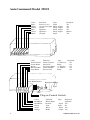
v 5.3
“Add-On”
Remote Control Car Starter
Model 25522
Installation Manual
For use on automatic vehicles only.
For gasoline or diesel vehicles.
© 2005 Directed Electronics, Inc.
1
Congratulations on your purchase of the AutoCommand® Remote Car Starter.
The AutoCommand® Remote Car Starter system allows you to start the car by
remote control from the comfort of your home or office in order to cool it down in
the summer or heat it up in the winter.
This model 25522 is an “add-on” unit and must be used in conjunction with
another remote control unit such as a remote car alarm or keyless entry system.
AutoCommand® is for automatic transmission cars only. It is an extremely sophisticated system with multiple built-in safety and security features.
The AutoCommand® Remote Car Starter:
•
Will start your car by remote control, and run the heater, defroster, or air
conditioner to warm up or cool down the car.
•
Is designed to start the car if it is in park, and only if the hood is closed.
•
Can monitor the engine’s speed using a special tachometer monitoring circuit.
•
Will attempt to start the car for up to six seconds, but no longer (to avoid
damage to the starter motor). Should the car not start, or if it stalls after
starting, the AutoCommand® will make 2 further attempts to start it.
•
Will not let the car be driven without the key in the ignition.
•
Shuts itself off automatically after 10 or 15 minutes (user selectable) if you
forget to come out to your car.
•
Will shut off if the brake pedal is pushed, the hood is opened, or the transmission is shifted out of park - unless the key is in the ignition and in the
“run” position.
•
Allows you to remove the key while leaving the car running with the doors
locked for up to 10 or 15 minutes utilizing the QUICK STOPTM option.
•
Starts the car automatically should the temperature drop below 0°F (-18°C),
or if the battery voltage drops below 11 volts with the VACATION option.
•
Is quality engineered and microprocessor controlled to provide many years
of reliable use.
2
© 2005 Directed Electronics, Inc.
!! WARNING !!
Do not connect this AutoCommand® to a manual transmission vehicle. Doing
so could cause serious property damage, personal injury, and will void all
warranties.
Tools required to install the AutoCommand® unit:
Wire cutters/strippers
Soldering iron
Pliers
Screwdrivers
Test meter
Drill and 1/2” bit
We highly recommend that all connections be soldered for reliability.
Parts list
AutoCommand® module
Bag of Parts
Control harness (10 position)
6 Power & Ignition wires
Parts kit in plastic bag:
30 A Fuse
3 Tab Connectors
On/Off Control Switch
Warning Label
Window Decal
Ring Terminal
Hood Pin Switch Set
2 Cable Ties
© 2005 Directed Electronics, Inc.
3
AutoCommand Model 25522
Color
Pink
White
Yellow
Blue
Green
Black
Function
Power(+12V)
Accessory/Lights
Starter
Ignition 1
Ignition 2
Ground
Color
Yellow/Green
Green/White
Brown
Brown/White
Gray/Black
Left White Button
Type
Input
Relay output
Relay output
Relay output
Relay output
Input
Function
Alarm Control
Sensor IN
Accessory Pulse
Alarm Disable
Sensor OUT
Required
Yes
Yes
Yes
Yes
Maybe
Yes
Type
Required
(+) 400 mA
No
Relay
No
(-) 400 mA
No
(-) 400mA
No
Relay
No
Right Red Button
LED
Plug-in Control Switch
Color
Red/Black
Red/White
Green
Violet
Orange
4
Function
Diesel Input
Remote
Tach
Hood
Brake
Type
Required
Optional
- Input Yes
Input
No
- Input Yes
+ Input Yes
© 2005 Directed Electronics, Inc.
!! WARNING !!
On cars with airbags, you may notice bright yellow tubes or harnesses underneath the steering column area. DO NOT tamper with these wires in any way,
so as to prevent personal injury and/or damage to the air bag system.
Battery gases are explosive. Do not smoke while working near the car’s battery.
!!CAUTION!!
When working the wires through the car’s firewall, be sure to protect them
from sharp metal edges and from hot surfaces on the engine.
Note: Some installers connect a battery charger to the vehicle’s battery during installation. This is fine, but it must be removed before running the vehicle
under AutoCommand® control.
INSTALLATION INSTRUCTIONS
1. Before You Start
Take the time to read through the whole installation manual.
Wire Harnesses: Before installation, always check that your wire
harness matches the list/drawing on page 4 of the manual.
IMPORTANT: After having read the entire manual, start the
installation by putting the yellow WARNING STICKER in the engine compartment. Choose a surface that is clean and readily visible when the hood is
open.
© 2005 Directed Electronics, Inc.
5
POWER & IGNITION WIRES
The AutoCommand® module will be installed under the dash once all wiring has
been completed. Do not mount the module at this time! You will need to check
the diagnostic light (LED) as the installation progresses. Locate (or drill) a
hole in the firewall to run the VIOLET (hood) and the GREEN (tach) wires of the
Control Harness and the PINK wire of the Power Harness through into the
engine compartment. The remaining short wires stay in the passenger area.
Leave about a foot of the wire harness under the dash for ease of working and
visual access to the diagnostic lights.
Note:
Always connect the Black and Pink wires before connecting
any of the other wires.
2. Black Wire (14 AWG)
Ground
Connect this BLACK wire to a very good, clean chassis ground in the driver’s
kick panel area. Use the small red ring terminal if needed. The metal bracing
around or beneath the dash board is not adequate.
3. Pink Wire (12 AWG)
Power (+12V)
Plug this wire onto the spade terminal marked Power. Run the other end
of this wire through the firewall of your vehicle and to the positive side
of the vehicle’s battery terminal. Connect the ring terminal of the fuse
holder provided to the vehicle’s positive battery post. Join the remaining
ends of the power wire together by soldering them. Alternatively, you
may wish to use a Yellow butt terminal, but we recommend soldering.
Ignition Key Diagram for Steps 4-7
The vehicle’s wires are found coming off of the key switch.
Lock/Off
ACC
6
ACC
RUN
START
© 2005 Directed Electronics, Inc.
4 Blue Wire (14 AWG)
Ignition 1
Connect the LIGHT BLUE wire to the ignition 1 wire of your vehicle. This
wire will measure +12V on the test meter in the “run” and “start” position, and
is off (ground) in the “lock/off” and “accessory” positions).
5. Green (14 AWG)
Ignition 2
Connect the GREEN wire to the second IGN2 wire of your vehicle. This is a
wire that is hot in the “run” and sometimes “start”.
6. White Wire (14 AWG)
Accessory / Lights
Connect the WHITE wire to the accessory wire which is +12V in the “run” and
“accessory” position, but off (ground) in the “start” and “off” positions. This
wire will power the heater / air conditioner (in some cars).
This WHITE wire can also be used as the headlights wire if you do not need it
for the Accessory position -- or if you power the heater / air conditioner with
the GREEN IGN2 wire. Simply connect this WHITE wire to the low beam
connection of the headlights or to the parking lights. Do not use this wire for to
power both Accessory AND Headlights together unless you use 2 external relays powered by this WHITE wire -- one for the headlights and the other for the
Accessories.
7. Yellow (14 AWG)
Starter
Connect the YELLOW wire to the starter wire. This wire is hot in the “start”
position only.
Note: Nissan vehicles have two starter wires. Connect both starter wires to the
YELLOW wire.
8. Control Switch
Plug-in Switch
Plug the Control Switch into the AutoCommand on the side next to the push
buttons and led light. Mount the switch using a 1/2” drill bit.
© 2005 Directed Electronics, Inc.
7
Control Harness (All wires are the smaller 18 AWG size)
9. Violet Wire
Hood Pin Switch Control Harness
The hood pin switch MUST be installed with the AutoCommand®. It prevents operation of the AutoCommand® when the hood is open. Connect the
VIOLET wire to the hood pin switch using
the red connector.
Note:
If you already have a hood pin
switch which is being used by a
car alarm system, you may share
the wiring -- but be sure to diode
isolate each wire going to the
hood pin switch with the bands
of diodes pointing towards the
pin switch as follows:
10. Orange Wire
Brake Shut-off
Control Harness
The ORANGE 18 gauge wire will disable the AutoCommand® when the brake
pedal is pressed down. This is an added anti-theft safety feature. This connection is usually made under or behind the brake pedal linkage at the switch.
Connect the ORANGE to the wire that receives +12 volt only when the brake
pedal is pressed down. Any +12 volt input on this wire will shut off the AutoCommand®. In some cars, the ignition must be on to see the power at the brake
wire. This wire must be hooked up. This is a critical safety feature. This hookup is also required for other options discussed later.
8
© 2005 Directed Electronics, Inc.
11. Initializing the AutoCommand®
BEFORE THE CAR WILL START FOR THE FIRST TIME, YOU MUST INITIALIZE THE
AUTOCOMMAND TO SHOW THE UNIT THAT IT IS IN AN AUTOMATIC VEHICLE.
A. The AutoCommand® requires the installer to press and hold the
brake pedal while the Hood is open.
B. While depressing the brake pedal (with the engine off) turn the
ignition key to the “RUN” (not “start”) position.
C. Put the car in gear from the “PARK” position.
D. Put the car back in “PARK” and release the brake pedal.
Confirm initialization by turning the ON/OFF control switch “OFF” and then
“ON”. The red LED on the AutoCommand® module will flash once immediately
as the switch is flipped from the “OFF” to the “ON” position.
IF THE UNIT DOES NOT INITIALIZE AT THIS TIME, REPEAT STEPS
A THROUGH D ABOVE.
12. Green Wire
Tach Input
Control Harness
The AutoCommand® has two ways of monitoring the car during the starting
process. Both ways will ensure a clean, accurate start. Read about both methods before deciding which one to use. Normally you should try the “No TachTM”
method first.
“No TachTM” Starting
This starting method does not require the connection of the GREEN tach wire.
This method will start the car by reading the car’s voltage before attempting to
start, and then looking for a voltage increase when the alternator kicks in. This
feature automatically takes into account voltage, temperature, and the time since
the vehicle was last run. The “No-TachTM” starting is preset at the factory and
you can skip step 12A if you would like to use it. Note that if the vehicle is hard
to start, set option #3 (page 14) for “extended crank.”
Tachometer sensing
If the vehicle is generally hard starting (requiring a cranking time of more than
1 second) you will get more accurate starting with the tachometer sensing starting method. This method starts the car by reading the engine speed (tach)
information from a wire under the hood. If you choose tachometer sensing,
connect the GREEN (18 awg) wire to the car’s tach wire under the hood. After
you have connected the GREEN wire, you need to teach the AutoCommand®
the vehicle’s tach rate. Proceed to step 12A.
Note: You must have already initialized the vehicle.
© 2005 Directed Electronics, Inc.
9
12A. Tach Rate Learning
Note: Only use if the tachometer sensing method is chosen.
A. Connect the GREEN wire to the car’s tach wire under the hood.
B. Turn the On/Off control switch to the “OFF” position. Wait 5 seconds
for the flashing of the red LED to stop.
C. Push the white button to the left of the red LED once and you will see the
red LED flash. Now push the red button on the right side for a second
until you see the red LED flash again. You are now in TACH mode. (If
the LED flashed twice -- simply push the right button again until you get
only one flash).
D. Wait 5 seconds for the red LED to flash 3 times.
E. Turn the On/Off control switch back to the “ON” position
F. Start the car and let it get to a normal idle. Do not press on the gas pedal.
G. Push the red button to the right of the red LED.
H. Watch the red LED. It will turn on (solidly) after 3 or 4 seconds,
indicating that the idle rate has been learned.
I. Turn the key to the “Lock/Off” position.
Note: Once this step is complete, the red LED should remain lit only when the engine
is running (at up to twice the learned idle rate--above this rate the LED light
should shut off). THIS IS CRITICAL. Confirm this by running the engine
(with the key in the ignition) and pressing the gas pedal to raise the idle rate to
twice the normal rate. The red LED should turn off. If it does not turn off,
repeat the tach rate learning step and check the GREEN wire connection and
location.
13. Red/White Wire
Remote Input
Control Harness
The RED/WHITE wire is used to trigger the AutoCommand® to start. Giving this wire
a negative pulse will cause the AutoCommand® to start. Giving it another negative pulse
will cause it to stop.
Hook this wire up to the output wire of your remote car alarm or keyless entry system.
Or, hook it to the lock or unlock wire of your vehicle and set Option 8 as described in
Section 21.
1 0
© 2005 Directed Electronics, Inc.
OPTIONAL STEPS
Many of the optional steps require a relay to be hooked up. The most common relay
used for this type of application is the Bosch type automotive relay P/N 0332
209150. Use the diagrams below for a typical hookup. If you use another type of
relay, then you need to know that pins 85 and 86 in this diagram represent the coils
of the relay. Pin 30 is the common and pin 87 is the normally open contact. If your
relay has a pin 87A, then it is not used for these applications. The diagrams below are
typically used for applications such as headlamp or parking lamp connections.
14. Yellow/Green
Alarm Control
Control Harn
The YELLOW/GREEN wire is specifically designed to control the Ignition Input
of the remote control alarm system which is triggering the AutoCommand. Connect
this YELLOW/GREEN wire directly to the Ignition Input of the alarm. This YELLOW/GREEN wire will go to +12 volts anytime it sees +12 volts on the
AutoCommand’s BLUE IGN 1 wire from the key. Thus this output follows the IGN
1 status. The only exception is that when the AutoCommand is powering up the
vehicle this wire will not activate. Thus the alarm remains operational during
AutoCommand control -- but not otherwise when the key alone is controlling the
igntion. This is a 300 mA transistor positive output.
15. GREEN/WHITE
GRAY/BLACK
Sensor Loop IN
Sensor Loop OUT
Control Harn
Control Harn
This GREEN/WHITE wire is the input to a normally closed relay. When the AutoCommand is running -- this relay opens. Thus if you have an external sensor such as
a shock sensor -- you can pass this sensor’s output through the AutoCommand.
When the AutoCommand is running -- this sensor is opened -- or bypassed.
Cut the sensor output wire in half. Connect one side to this GREEN/WHITE wire
and the other side of the cut sensor wire to the GRAY/BLACK wire.
© 2005 Directed Electronics, Inc.
11
16. Brown Wire
Acc. Pulse
Control Harness
The optional BROWN wire is the Accessory Pulse output which gives out a 1 second
transistor ground output just as the Accessory wire comes on. This is important in
some vehicles to control the defroster or to control the GM R.A.P. system. Again, this
is a 400 mA transistor ground output which MUST drive a relay (not included).
17. Brown/White
Alarm Disable
Control Harness
The optional BROWN/WHITE wire will put out a 1 second negative pulse
just before starting the vehicle. This wire can be used to turn off the factory
alarm system in vehicles that have them.
Note:
On most vehicles, this wire can be connected directly to the
factory alarm/disarm wire which is usually located in the driver's
kick panel.
18. Red/Black
Diesel Input
Control Harness
The optional RED/BLACK wire will sense the turning on and off of the Diesel
Glow-Plug light to determine when to crank the vehicle. Hook this wire to the
switched wire of the diesel glow-plug light or to the glow-plug wire itself.
Required Final Steps
19. Trying the Unit Out
WARNING: Be prepared to apply the brake during this testing. Close the
hood, fully apply the emergency brake, and place the vehicle in Park.
A. Once all the wiring is checked and is correct, put the car in
park, then press the button on the transmitter of the host alarm
or keyless entry system which controls the AutoCommand.
B. The car should start and continue to run for ten minutes. Please
make sure that the engine shuts down if the car is taken out of
park, the hood is opened or the brake is pressed.
1 2
© 2005 Directed Electronics, Inc.
20. Trouble Shooting with the Self Diagnostics
The AutoCommand® contains a built in diagnostic routine that will indicate
why the unit turned off the car the last time that the unit was used. To activate
the diagnostic mode, simply turn the On/Off control switch to the “OFF” position. In a few seconds, the red LED on the module will flash 1 to 12 times to
identify the problem. See the chart below for an explanation of the flashes:
1 flash
2 flashes
3 flashes
4 flashes
5 flashes
6 flashes
8 flashes
12 flashes
10/15 minute time out -- unit should be fine.
Brake or Hood activated
No Tach or Stalled. Check tach learning. Or confirm that
the alternator is being powered up by one of the ignition wires.
Received another remote input signal.
Transmission was shifted into gear. See Trouble-Shooting
Guide. Move the In-Gear switch inside the receiver module to
the OFF position (see diagram below for location of In-Gear
switch).
Low battery voltage, or may be missing an ignition wire
which powers up the alternator
Over-current. A transistor output is being over driven.
The control switch was turned off.
In order to get an accurate diagnostic, allow the unit to go through its complete
starting cycle(s). The unit may only try to start once or it may try 3 times. In
order to get an accurate reading, please wait 45 seconds after its last attempt to
start.
© 2005 Directed Electronics, Inc.
13
21. Special Programming Options
The AutoCommand® unit has 8 special options and features. You will not need
to use these special options in most situations. The factory settings will operate most vehicles. You must turn the On/Off control switch to the “OFF”
position to program any features. Note that when turning off this control
switch, the red LED will flash a few times, giving the diagnostic code described
in Section 20. Wait a few seconds for it to finish before programming your new
Options.
#
Factory Setting (2 flashes)
Option (1 flash)
1
“No-Tach”
Tach Mode
2
10 min. run time
15 min. run time
3
Normal Crank
Extended Crank
4
Normal Crank
Super Crank
5
Normal Voltage Metering
Ignore Voltage Metering
6
Gasoline vehicles
Diesel vehicles
7
“Enable” feature
No “Enable”
8
Normal Trigger
Double Pulse Trigger
#1 sets the starting method. The factory setting uses “No-Tach” starting. If you wish to use the tach to start, follow the instructions in 12A.
#2 is for the choice of run times.
#3 will add 50% more crank time to “No-Tach” starting.
#4 adds 100% more crank time. This is necessary on many deisel a n d
hard to start vehicles. Options #3 and #4 can be added together for
even more cranking time.
#5 is used in the “No-Tach” starting method for some diesel vehicles.
#6 option must be activated when installing on a diesel vehicle.
#7 cancels the Enable mode safety feature. The Enable mode requires
that the driver toggle the ON/OFF control switch “OFF” then “ON” in
order to “enable” the vehicle for AutoCommand® control. This feature
guards against undesired starting of the vehicle by remote control.
#8 Normal Trigger will start and stop the AutoCommand with a single
quick ground pulse to the Remote Input wire of Step 13. Double Pulse
Trigger mode will not activate the AutoCommand until it has seen two
pulses within 3 seconds time. Thus if you hook the Remote Input wire
up to the Door Lock wire of your keyless entry module -- you can lock
1 4
© 2005 Directed Electronics, Inc.
the doors with just one push of the transmitter’s Lock button. If you
push transmitter’s Lock button again within 3 seconds -- you will lock
AND start the vehicle.
SETTING PROGRAM OPTIONS:
If you want the factory setting, DO NOTHING and skip this section. If you
want to change to one of the options, TURN THE ON/OFF
CONTROL SWITCH TO THE “OFF” POSITION. Wait for the red LED to
stop flashing, then continue with the following procedures:
A. Push the white button to the left of the red LED. Each time you
push the white button the red LED will flash 1 to 8 times signifying
at which option you are (press it once, the LED flashes once. Press
it again and it will flash two times. Press it again and it will flash
three times, etc., to show what option you are at).
B. When you are at the option level you desire, push the red button for
a second and the red LED will flash once for Option setting and
Twice for Factory setting.
C. You can choose the next option by pushing the left button again to
index to the next option. When you get to the next option you want
to change, simply repeat Step B above. After six seconds, the
AutoCommand® automatically exits the programming mode (Three
LED flashes).
D. Turn the Control Switch back ON and confirm that the LED flashes
once as the switch is turned ON.
SPECIAL CASES
1) VATS system (for GM cars with special PASS key).
If you have a GM vehicle with a factory anti-theft system (a resistor in the key),
you need to follow these directions:
Measure the resistance of the key. It should be between 392 ohms and 11,800
ohms. To do this, put the ohm meter probes on each side of the key pellet. This
value should be close to one of the following (all values in ohms): 392, 523,
681, 887, 1.13K, 1.47K, 1.87K, 3.01K, 3.74K, 4.75K, 6.04K, 7.5K, 9.53K,
11.8K. Purchase a resistor with a value within 5% of this measured value and
a 30 amp BOSCH type relay.
Locate the pair of VATS wires (sometimes White/Black striped and Purple/
Black striped) running behind the dash from the passenger side to the driver’s
© 2005 Directed Electronics, Inc.
15
side behind the key switch. Connect our Ignition 2 (GREEN) wire to pin 86 and
ground to pin 85 on the relay. NOTE: You will have to use IGN 1 to power up all
of the Ignition wires behind the key -- since IGN 2 needs to be used here for the
VATS relay. Cut ONE of the VATS wires and connect the key-switch side to NC
pin 87A, and the other side (Engine Side) to common pin 30. Connect the other
VATS wire to NO pin 87 with the selected resistor soldered in line as shown
here:
Most of the 1990-1995 Cadillacs have a slight variation on the wiring for the VATS
system. On these cars, there is an ORANGE wire (actually a vinyl sleeve) that contains
smaller wires. This is located underneath the steering column next to the YELLOW
sleeve that is labeled “Air bag wiring” -- do not cut this Yellow sleeve. Slit the ORANGE
sleeve open to expose two pairs of wires which are either both white, OR both yellow,
OR both black.
Note:
When installing a GM vehicle with a VATS bypass system, the GREEN IGN
2 wire must only go to the VATS relay. If you need IGN2 in the car, simply
supply power to the IGN2 wire of the vehicle by jumping power from the
BLUE IGN1 wire. (Thus BLUE will be powering up 2 wires behind the key
-- and in some cases 3 wires).
2) Diesel Vehicles: You must hook the RED/BLACK wire up to the diesel
glow-plug light wire or to the positive side of the vlow plugs itself as described in
STEP 18.
The following chart outlines the options that need to be set for diesel vehicles. (Use
the Chrysler settings for all other diesel vehicles.)
Option
3
4
Ext. Crank Super Crank
Chrysler
X
Ford
X
Chevrolet X
X
1 6
5
IgnoreMeter
X
X
6
Diesel
X
X
X
© 2005 Directed Electronics, Inc.
3) General Motors Passlock™ Security System Bypass
New GM PASSLOCK® Anti-Theft System for 1995 through 1997 models
Beginning in 1995 and 1996 GM introduced a new version of their old VATS
security system. This new PASSLOCK® system will only be found in the 1995
Chevrolet Z24 Cavalier, Pontiac Sunfire GT only, 1996+ Pontiac Grand Am,
Oldsmobile Achieva, and the Buick Skylark, Chevrolet Cavalier and Pontiac
Sunfire. You can determine if the vehicle is equipped with this system by checking for a “Security” or “Theft” light on the dash panel. Basically, what they
have done is taken the resistor that was part of the key on the original VATS and
moved it to inside the lock cylinder of the steering column. They have also set
additional parameters to make this even more complicated. To bypass this
system, use the following diagram and instructions. Follow these instructions
very carefully and remember that the resistance must be within 5% of the correct measured value.
Note that for these vehicles with PASSLOCK, the AutoCommand’s Green Ignition 2 wire goes to the vehicle’s White Ignition wire. The AutoCommand’s
White Accessory wire goes to the Vehicle’s Orange Ignition wire.
1. Remove the top and bottom halves of the steering column shroud.
2. Locate the small three wire harness (with White, Black and Yellow wires) running down from
the ignition key cylinder on the top right hand side of the steering column into the instrument
panel.
3. Cut the Yellow wire in half and bare back the Black wire.
4. With the ignition key in and turned to the “ON” or “RUN” position, measure the resistance
between the key side of the Yellow wire and the Black wire. Make several measurements to
verify that you have a consistent resistance. You also need to change your test leads around.
You will find that you get two different readings. So far we have found that the higher of the
two readings is the correct resistance.
5. When you have correctly identified the correct resistance obtain a resistance of the same value.
6. Locate the Black “Bulb Test” wire on the left side of the steering column in cavity “D” or “E”
of the Black 5-way connector, just above the main ignition switch connector.
7. Wire the relay as shown in the following Diagram.
© 2005 Directed Electronics, Inc.
17
4) New GM PASSLOCK® II Anti-Theft System for 1998 model
vehicles. In 1997 the Malibu/Cutlass and then in 1998 all truck platforms (Full size
Pickup, Suburban, S-10/Sonoma, Blazer/Jimmy, Tahoe/Yukon and Astro/Safari) came out
with this new Passlock II system.
Use the diagram above and the list below to interface to this new type system. Note that the
Yellow wire for the Passlock is a similar gauge wire to the Starter wire. Don’t confuse these.
You must acquire a resistor value within 5% of the value of the resistor in the key. Additionally,
there is No BULB TEST wire on this system, so pin 87 is not used.
Substitute as follows:
Wire color above
‘Black or Yellow’
‘Black’
‘Black/White or White’
Trucks
Yellow
Orange/Black
Red/White
Malibu / Clutlass
Yellow
Black
Red/White
Important Note:
Make sure that all drivers who will be operating the AutoCommand® are fully
aware of the safety precautions installed and their limitations. Stress the importance of switching the On/Off control switch to the “OFF” position (down) every
time the car is serviced. Show the user how the control switch must be turned off
and on again after pulling out the key before leaving the car.
limited lifetime consumer warranty
Directed Electronics, Inc. (hereinafter “Directed”) promises to the original purchaser to
repair or replace with a comparable reconditioned Directed add-on remote start unit if
this Directed add-on remote start unit (hereinafter “Unit”), excluding without
limitation, any remote transmitters or associated accessories, proves defective in
materials or workmanship under normal use for the life of the vehicle which the Unit is
originally installed. During this period, so long as the Unit remained installed in the
original vehicle, Directed will at its option, repair or replace this Unit if it is proved
defective in workmanship or material PROVIDED the Unit is returned to Directed’s
warranty department at One Viper Way, Vista, CA 92081, along with $20 postage and
handling fee, a bill of sale or other dated proof of purchase bearing the following
information: Date of purchase, name and location of the merchant who sold the Unit,
and product description. This warranty does not cover labor costs for the removal or
reinstallation of the Unit. This warranty is non-transferable and does not apply to any
Unit that has been modified or used in a manner contrary to its intended purpose, and
this warranty does not cover damage to any Unit caused by installation or removal of
the Unit. This warranty is void if the Unit has been damaged by accident or
unreasonable use, neglect, improper service or other causes not arising out of defects in
materials or workmanship. Directed makes no warranty against theft of a vehicle or its
contents.
1 8
© 2005 Directed Electronics, Inc.
THE FOREGOING WARRANTY IS THE EXCLUSIVE PRODUCT WARRANTY,
OTHERWISE, ALL WARRANTIES INCLUDING BUT NOT LIMITED TO
EXPRESS WARRANTY, IMPLIED WARRANTY, WARRANTY OF
MERCHANTABILITY, OR FITNESS FOR A PARTICULAR PURPOSE ARE
EXPRESSLY EXCLUDED AND DISCLAIMED TO THE MAXIMUM EXTENT
ALLOWED BY LAW, AND DIRECTED NEITHER ASSUMES NOR
AUTHORIZES ANY PERSON TO ASSUME FOR IT ANY LIABILITY IN
CONNECTION WITH THE SALE OF THE PRODUCT. DIRECTED HAS
ABSOLUTELY NO LIABILITY FOR ANY AND ALL ACTS OF THIRD PARTIES
INCLUDING ITS AUTHORIZED DEALERS OR INSTALLERS. SOME STATES
DO NOT ALLOW THE LIMITATION ON HOW LONG AN IMPLIED
WARRANTY LASTS, SO THE ABOVE LIMITATION MAY NOT APPLY TO YOU.
LIMITATION OF DAMAGES AND LIABILITY. CONSUMER’S REMEDY IS
LIMITED TO REPAIR OR REPLACEMENT OF THE UNIT, AND IN NO
EVENT SHALL DIRECTED’S LIABILITY EXCEED THE PURCHASE PRICE OF
THE UNIT. IN ANY EVENT, DIRECTED SHALL NOT BE LIABLE FOR ANY
DAMAGES INCLUDING, BUT NOT LIMITED TO, ANY DIRECT, INDIRECT,
INCIDENTAL, SPECIAL, PUNITIVE OR CONSEQUENTIAL DAMAGES, LOST
PROFITS, LOST SAVINGS, OR, TO THE EXTENT ALLOWED BY APPLICABLE
LAW, DAMAGES RESULTING FROM DEATH OR INJURY ARISING OUT OF
OR IN CONNECTION WITH THE INSTALLATION, USE, IMPROPER USE,
OR INABILITY TO USE, THE PRODUCT, EVEN IF THE PARTY HAS BEEN
ADVISED OF THE POSSIBILITY OF SUCH DAMAGES. SOME STATES DO
NOT ALLOW THE EXCLUSION OF LIMITATION OF INCIDENTAL OR
CONSEQUENTIAL DAMAGES, SO THE ABOVE LIMITATIONS OR
EXCLUSION MAY NOT APPLY TO YOU. THE CONSUMER AGREES AND
CONSENTS THAT ALL DISPUTES BETWEEN THE CONSUMER AND
DIRECTED SHALL BE RESOLVED IN ACCORDANCE WITH CALIFORNIA
LAWS IN SAN DIEGO COUNTY, CALIFORNIA.
IMPORTANT NOTE:
This product warranty is automatically void if its date code or serial number is defaced,
missing, or altered.
Make sure you have all of the following information from your dealer:
A clear copy of the sales receipt, showing the following:
➤ Date of purchase
➤ Authorized dealer’s company name and address
➤ Item number
© 2005 Directed Electronics, Inc.
19
The company behind this system is Directed Electronics, Inc.
Since its inception, Directed Electronics has had one purpose, to provide consumers
with the finest vehicle security and car stereo products and accessories available. The
recipient of nearly 100 patents and Innovations Awards in the field of advanced
electronic technology, DIRECTED is ISO 9001 registered.
Quality Directed Electronics products are sold and serviced throughout North America
and around the world.
Call (800) 274-0200 for more information about our products and services.
Directed Electronics is committed to delivering world class quality products
and services that excite and delight our customers.
Directed Electronics, Inc.
Vista, CA 92081
www.designtech-intl.com
www.directed.com
© 2005 Directed Electronics, Inc. – All rights reserved
06-05
Trouble-Shooting Guide
Unit won’t respond
Make sure unit has power and ground.
Make sure unit is initialized (See ‘Initializing the unit’ in the manual)
Re-program transmitter. (See ‘Code Learning’ under Special Cases in the manual).
What is the Diagnostic
Code, and how do I
get it?
Diagnostic Code 1 flash
Check Diagnostic Code as described in Trouble Shooting with Self Diagnostics in the manual.
The Self-Diagnostics built into every DesignTech brand remote start will help identify problems in both the unit and
your installation. To get an accurate diagnostic code, flip the toggle switch off and back on; the LED light (on
module) should flash once if the unit is initialized. Press the start button on your transmitter for second. Now allow
the unit to try and start your vehicle 1-3 times. (Note that the unit will attempt to start the vehicle up to 3 times unless
codes 2,5,7 or 8 are being triggered, when it will try and start the vehicle once). Allow it up to a minute to try to start
again on its own - Don’t do ANYTHING to the unit during this time, unless something goes obviously wrong. At the
end of the starting cycles, turn the toggle off and count the first series of flashes- this will be the diagnostic code.
The unit may not have attempted to start the vehicle yet or the unit may have started and timed out.
Is the toggle switch upside down? When the switch is turned on the LED will flash once immediately.
Something might be causing the unit to reset, such as a poor connection to ground or power, or you may have a relay
wired improperly. Typically the wires in the control harness require a relay unless otherwise stated.
Diagnostic Code 2 flashes
The transmitter may need to be programmed.
The unit thinks the hood is open. Make sure the hood pin-switch is properly adjusted and installed.
The unit thinks the brake is being depressed. Make sure the brake wire has 12 volts on it only when the brake is
depressed. There should be no voltage on the brake wire at any other time
Diagnostic Code 3 flashes
You might be experiencing feedback if you have connected the parking or head-lights. If disconnecting the lights
wire allows the unit to start then you might power the headlights, or you can isolate the brake wire of the unit from
the vehicle with a relay.
If the unit is programmed for tach, the tach wire is not connected or the tach rate may not yet have been learned.
If the unit is programmed for ‘No-Tach’ the vehicle may not have all the required ignition wires connected, or may be
equipped with a factory security system – thus causing it to stall.
Diagnostic Code 4 flashes
Sometimes a unit may have an option programmed even though you did not specifically set that option. Try re-setting
the unit. Unplug everything from the module except the black ground wire and LED (if you have a plug-in LED).
While pressing the white button on the module, connect the power lead. The LED on the unit should turn on and stay
on. Release the white push button and the LED should remain illuminated. (If not, repeat the process being sure to
hold in the white button while connecting power.) Now remove power and wait 2 minutes. Then connect the power
without pushing any buttons. Re-Initialize the unit and it should work for you.
Make sure the remote input wire (usually red/white) is not touching anything. (This wire is not on all models). If you
have a stick shift unit – this is not relevant to you.
You might be pressing the remote control again before the unit has completed its cycle(s)---See 'Diagnostics: What is
the Diagnostic code and how do I get it?’ – at the top of this page.
Diagnostic Code 5 flashes
Diagnostic Code 6 flashes
If installing a manual transmission unit, this code means the unit did not see the door pin-switch.
This code means the unit thought the transmission was shifted into gear.
If the transmission was not shifted: Switch the “in-gear” switch inside the module to the off position. This disables
‘Transmission in Gear’ sensing, and should solve the problem.
Code 6 is caused by the unit not seeing the battery voltage increase enough when the vehicle starts. It can also be
caused if you are not bypassing the factory theft system, such as PATS, VATS, or similar, if equipped.
Double-check the ignition wiring against the vehicle-wiring guide. Your vehicle may require ignition 2, or in some
cases ignition 3, in order to allow the alternator to function – thus bringing up the voltage.
Diagnostic Code 7 flashes
Diagnostic Code 8 flashes
Diagnostic Code 9 flashes
Diagnostic Code 10/11 flashes
Diagnostic Code 12 flashes
© 2005 Directed Electronics, Inc.
If the wiring is correct, and you are properly bypassing any security system the vehicle may be equipped with, then
connecting the unit into tach mode should solve the problem. (Your alternator may not be functioning properly).
An alarm sensor was triggered, causing the vehicle to shut down. (Only applies to units that have alarm features).
Something in the control harness is not connected properly. One of the transistor outputs is driving too much current.
There may be a wire connected without a required relay, or if you are using a relay, the relay may not be connected
properly.
Applicable only to manual transmission units. Indicates the unit did not see the emergency brake.
These are not a valid codes.
Make sure you have an accurate code. Please see ‘What is the Diagnostic Code, and how do I get it?’ at the top of
this page. If you still get code 12, one of the toggle switch wires may have touched ground, possibly damaging the
unit. Or maybe the switch was just turned off while it was running. Or maybe a defective switch?
1
Trouble Shooting v4-1
Initialization - What is
it?
Initialization - What if
the unit will not
initialize?
Initialization is a process which proves to the unit that you have connected the required safety features and that the
unit has been installed in an automatic vehicle. See “Initializing the Remote Starter” in the manual.
DO NOT ATTEMPT TO INITIALIZE or INSTALL ANY AUTOMATIC UNIT ON ANY MANUAL
TRANSMISSION VEHICLE! Attempting to force an automatic unit to function on a manual stick-shift
vehicle could result in serious property damage or personal injury!
Is the unit already initialized? Make sure the switch is not upside down. Toggle the switch off and then
back to on. As the switch is turned on, the LED light on the unit (or that plugs into the unit) will flash
once if the unit is initialized.
One of the ignition wires may have voltage on it. Make sure all ignition wires measure a “dead” 0 volts
when the key is “off.” (It is normal to measure a small amount of voltage from the unit’s start wire.)
Check that there is 12 volts on the orange wire in the control harness only when the brake is pressed.
Check that there is continuity to ground on the purple wire in the control harness only when the hood is
open.
(A good way to test both the hood and brake at the same time is to connect a test light – the kind with a real light bulb
– with one lead to the orange wire and the other lead from the test light connected to the purple wire. If you open the
hood and press the brake, the light will illuminate if both connections are correct.)
You may have the wrong start wire. Make sure the yellow start wire from the unit is connected to a wire
in the vehicle which shows 12 volts only when the key is in the start (cranking) position. The wire should
have power at no other time.
Did you mistakenly switch the “in-gear” switch inside the module? If so, the unit will not initialize. This
switch disables transmission in-gear sensing, and should only be switched if you have been instructed by
a technician to do so or you are getting a diagnostic code of 5 flashes.
Your vehicle may not have a neutral safety switch, such as pre 95 GM rear-wheel drive vehicles or Dodge
Dakotas built prior to 1996. Try this: Open the hood and place your foot on the brake. Start the vehicle
with the key. Turn the engine off and release the brake. If all of your connections are correct the unit
should be initialized at this point.
I have a GM Truck and
the “Check Engine”
light is on after remote
starting. What should I
do?
The vehicle cranks but
fails to actually start
My 3 button remote
control will lock the
doors but will not unlock
them.
Try bypassing the toggle switch temporarily in case a wire or connection to it is broken. Just unplug the
switch and jump across the two pins on the module that the switch plugs into with any metal object. As
you jump (short) the two pins together the LED should flash if the unit is initialized. NOTE- DO NOT
short any toggle switch wire to ground or probe the connector with a test light. Doing so may damage the
unit.
You most likely have one of the ignition wires connected wrong. Make sure you have connected:
From Unit
to Vehicle_______________________________
Ign1 (Blue)
PINK (hot in run and start)
Ign2 (Green)
WHITE or PINK/WHITE (hot in run and start)
ACC(White)
ORANGE (hot in run only)
If you have the ignition wires connected as above and still have a check engine light it is possible the unit
has been programmed to have ignition 2 “off during crank.” Please review the programming options
within the installation manual.
Please see “What is the diagnostic code and how do I get it?” Follow the steps for the diagnostic code
you receive. You are probably missing one of your second or third ignition wires. Or if it is a Nissan –
you probably have 2 starter wires which need to be shorted together.
Re-program the transmitter. Use the left button when teaching 3 button remote controls. When
programming the 5 button remote, use the start button. (Refer to the installation manual for the complete
steps on how to make the unit enter the code learning process.)
My 5 button remote will
not control lock/unlock
individually.
© 2005 Directed Electronics, Inc.
2
Trouble Shooting v4-1
The vehicle runs – but
without the heater or airconditioner.
I have poor range.
You are missing the 2nd (or 3rd) ignition wire or the accessory wire is not hooked up. Make sure the heater or airconditioner is left on when you leave the vehicle. On diesel vehicles – they may not come on for a few minutes until
after the vehicle is up and running.
My vehicle has Passlock
I or II and I cannot get a
resistance reading.
Many meters have a known issue with measuring passlock. This is not a fault of the meter, the installer, or
the manufacturer. These issues can cause problems such as getting a consistent reading of the resistance,
or the reading may be artificially inflated. It is our belief that the mid-to-high-end meters seem to
experience more problems measuring passlock than less expensive digital meters.
Can I use the
DesignTech Transmitter
with other brands of
products?
The LED on the unit
flashes constantly
The antenna coax wire may be crimped, cut or otherwise damaged. Try the antenna both vertically and horizontally
to determine the best performance. Make sure the receiver unit has a good chassis ground. Note that the higher you
hold the transmitter off the ground when pushing the button – the further distance you will get from the system.
One wire will have 0 volts - This is the wire you "tap" into-- we’ll call this WIRE #1 USUALLY BLACK
OR ORANGE/BLACK. One wire will have 5 volts or less- This is the wire you cut in half-- we'll call this
WIRE #2 USUALLY YELLOW. One wire will have aproximately 12 volts - This is the wire you leave
alone USUALLY WHITE OR BLACK/WHITE. With all PASSLOCK wires intact, turn the vehicle on
and bump the starter. Measure the voltage between the wire #1 and wire#2. Your meter should be set on
the 12 volt DC scale. RECORD THIS VOLTAGE. Without turning the key off - go ahead and separate
WIRE #2. Reconnect the Universal Alarm Bypass Module (Part #20402 or 29402) as described in the
installation manual with one exception - GROUND the wire that goes to the ignition 3 wire; you should
hear the bypass module click. Now measure the voltage between the ENGINE side of WIRE #2 and wire
#1. Your meter should be set on the 12 volt DC scale. Adjust the dip-switches and trim-pot on the bypass
module until the voltage being measured EXACTLY matches the recorded voltage obtained without the
module. Remove ground from the ignition 3 wire of the bypass module, turn the vehicle off and then
restart it. Look at the voltage again - and while monitoring it ground the ignition 3 wire of the bypass
again. If the module is set correctly the voltage should NOT change. Repeat again to verify - if you get
the same voltage every time then the module is set up perfectly. There is no chart to help you with this, it
is just trial and error -- but it will work regardless of the meter you are using.
NO. Due to proprietary technology DesignTech brand products will operate only with DesignTech brand
Transmitters. Likewise, a DesignTech transmitter will not operate another brand’s products.
The alarm within the unit, if equipped (as are most units with 3 or 5 button remotes) may be armed, or the
unit may be in valet mode.
Make sure the wires going to the toggle switch are not broken, and that the toggle switch is on.
The LED remains
illuminated at all times
The starter stays
engaged for 6 seconds.
Reset the unit - See “Resetting all options to the factory setting” in the instructions
It is normal for the LED to glow dimly. This indicates the unit is receiving power.
If the LED is at full brightness then one of the push-buttons may have been depressed when you applied
power, the LED may be plugged into the wrong jack, or something may be wrong within the unit.
If the unit is in tach mode – make sure the tach wire is properly connected and receiving the correct tach
rate.
If using the “No-Tach” method, make sure the unit is not programmed for tach mode, extended crank, or
super crank.
Make sure you have the correct start wire connected - the start wire in the vehicle should have 12 volts
only when the key is in the start position.
How will I know if I
need a relay?
Some vehicles such as Toyotas and Nissans, experience a starter feedback problem. Try temporarily
isolating the start wire from the key switch to identify this problem - simply cut the start wire in half
between the connecting point of the units start wire and the key switch. Get Installation Note #133 from
off our web-site or Fax On Demand.
If the output is labeled as a “+12 relay output” the unit contains a relay on that output - and you will only
need to use a relay if the vehicle requires a negative output.
If the output is labeled a “400ma Transistor Ground Output”, this means the unit supplies a ground up to a
maximum of 400ma. If more than 400ma is drawn through the output, the unit may shut down or it may
be damaged. Generally speaking, if the vehicle requires a ground and the unit supplies a ground you will
not need a relay. If the vehicle requires a positive and the unit supplies a ground, you will need to use a
relay. Likewise, if the vehicle requires a ground capable of more than 400ma you would need to use a
relay. See Installation Note 111, Basic Uses of the Relay from our web site or our Fax On Demand.
© 2005 Directed Electronics, Inc.
3
Trouble Shooting v4-1
Vehicle only remote
starts if I flip the toggle
switch off and back on
This condition is perfectly normal. This is a safety feature designed to prevent unauthorized starting. If
you have forgotten to flip the switch off and back on, you can still remote start the vehicle. Just hold the
start button down for 6 to 10 seconds instead of the usual 1 second. If you do not like this safety feature, it
can be permanently bypassed by programming option 7, explained under "Setting Programming Features"
or a similar section within the installation instructions.
The remote input wire available on some units (usually a red/white) may be connected to ground. The
remote input wire should be taped up if not being used so that it does not touch ground.
The car turns off when
the brake is pressed- but
as soon as I release the
brake the vehicle starts
again
The alarm has been armed and triggered – even if you did not hook it up. If the alarm features are not
The lights flash (and
being used, you must ground the ‘alarm trigger’ wire permanently, or set option 24 if available.
maybe even the horn)
when I step on the brake.
Program extended crank, or use tach mode.
The unit tries 2 or 3
times before getting the
vehicle up and running
Some General Comments:
•
For Your Safety, never install an automatic unit into a manual transmission (stick-shift) vehicle! Serious
property damage or personal injury including death may occur! Instead, use one of our special manual
transmission units, which will operate safely in a manual transmission vehicle.
•
When testing wires use only a digital multimeter, unless otherwise instructed. A test light (especially the
kind with a real light bulb) can severely damage electrical components in modern vehicles if used
improperly. Also, “computer safe” LED type test lights - with a red and/or green LED- are NOT airbag
safe! NEVER test ANY wire within an airbag system harness.
•
Always roll down at least one window in the vehicle before beginning work. This will prevent you from being
accidentally locked out of the vehicle.
•
It’s okay to have a battery charger on the battery while you are working on the vehicle, but the car starter will
not function correctly with the charger attached.
•
Specific vehicle information is available directly from www.designtech-intl.com. If you have trouble with the
colors in the wiring guide "matching up" then you may be in the wrong harness. You can make sure you are in
the correct harness by unplugging the wires. For example: With the ignition switch, if you unplug it and then
the vehicle no longer cranks, the blower and radio do not work, and the vehicle is for all purposes "dead" with
the key- then you have found the “ignition switch harness.” (Otherwise, you will need to continue searching...)
The same technique can be used for the brake, lights, horn, etc. Once you are sure you are in the correct
harness, if the wire colors still fail to match up then you will have to test the wires using a digital multimeter. It
is always best to verify any wire before connecting to it.
•
Most of the common questions that people ask are actually answered within the installation manual. Make sure
you have thoroughly reviewed it before calling for technical support. We recommend going through the
installation manual with two different colored markers. Read through each step and check it off after you have
read it. Use the second marker to make a check when you have completed the step in the vehicle. This will help
to make sure you have completed all steps, and that you have not missed any features the unit offers.
© 2005 Directed Electronics, Inc.
4
Trouble Shooting v4-1


![Page 1 www.Ludowici.com [**INSERT PIC] LUDOWICI TM Desde](http://vs1.manualzilla.com/store/data/006216944_1-046022ddb0fd4b43a805da73ee2d4dd9-150x150.png)