1
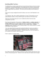
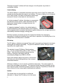
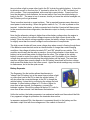
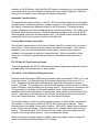
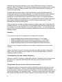
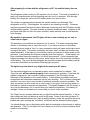
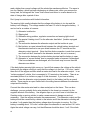
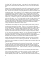
Release Version 6/12/13
Notes on Roadtrek Electrical Simulator
Disclaimer:
Use at your own risk. This simulator and these notes are not a substitute for professional
advice. Damage to your RV could occur if you do not follow the instructions provided by
Roadtrek. As an independent owner, the author developed the simulator and this
document to help answer questions posed by other owners.
The information provided here is offered, "as is" with no implied warranty as to the
accuracy or applicability to any of the Roadtrek vehicles and is intended for educational
purposes only.
Working on the electrical system in a motor home entails risks
even with the low voltage wiring. The risks include death,
serious injury and property damage. The AC line voltages can
kill by inducing cardiac ventricular fibrillation. Lead Acid
batteries store tremendous energy and can cause thermal and
acid burns. Batteries produce hydrogen gas which can explode.
The risk of fire must also be considered with the presence of
solid, liquid and gaseous combustible materials. The user must
take full responsibility and assess if he or she is qualified to use
this information.
Background:
The electrical system in your “mobile self contained living unit” is surprisingly complex.
There are multiple energy sources and both high and low voltage wiring. It’s no wonder
lots of folks are confused!
It’s my hope that this effort will enlighten both owners and professionals. I know that I’ve
been enlightened! Please let me know what you think and pass on your experiences.
[email protected]
When I first set out to build this simulator, I along with many others thought incorrectly
that all of these machines worked about the same way with only minor differences. Oh
how wrong I was!
1
Identifying What You Have:
Troubleshooting a complex system with an incorrect picture of what you have is a recipe
for frustration. An accurate description of the system as built is critical to resolving any
problem you might have. Someone may tell you that this is what you need to do and it
may not apply at all to your situation. So be sure you know what you have before you
start.
There are four major configurations which I believe cover most of the Roadtrek’s in use
today.
You might ask; “okay, tell me which configuration do I have?” This question is not so
easily answered, since not every model in a given year was built in the same way.
There are some simple tests you can run to determine which of the four basic
configurations you have.
First, there is the question of the presence of battery isolator or a battery separator. A
battery isolator allows the vehicle engine alternator to charge the RV battery but does
not allow the RV battery charger to charge the vehicle engine battery. A battery
separator makes it possible for the RV battery charger or the vehicle alternator to charge
both batteries at the same time.
Your user manual lists the components and should indicate if you have an isolator or
separator on the “Appliance & Accessory Manufacturer’s Log.” Manuals often have
errors, so your vehicle might not match. The best method is to look for the device on
your machine and compare it with the pictures.
Here is a picture of a typical isolator:
On a Chevy 190V 2002, the isolator is located on a frame member under the front of the
vehicle on the passenger side. I believe in most cases they are located near the engine.
2
A battery separator looks like this:
On the Sprinters I’ve looked at, the separator is located on the firewall on the driver side
of the engine compartment and is clearly visible when you open the hood. I don’t know
where it’s located on other vehicles.
The next question addresses the connection of the converter/charger to the battery.
Some of the schematics do not show the correct connection. The converter/charger can
The converter/charger output can connect to the RV battery directly (configuration #2) or
indirectly through the battery disconnect switch (configuration #1). In the period between
about 2005 and 2007, both configurations were used. Prior to this time all of the vehicles
had configuration #1 and after this period they all use configuration #2.
Prior to this time all of the vehicles had the direct connection and after this period they all
use the bypass connection.
There is an easy test to determine how your RV is configured. With the engine off, and
the battery disconnect in the off state, you should have no power to the 12 volt RV
accessories. Now plug the unit into shore power and notice that your microwave display
comes on. If the 12 volt RV lights and accessories can be turned on without touching the
battery disconnect switch, you have the direct connection configuration. If they don’t,
then you have the bypass configuration.
This simulator has a drop down selector and you can directly select one of the four
configurations if you know the answers to the above two questions.
I’ve also included a number of vehicle years and models so you can make the selection
based on the year and model. This is not completely reliable, particularly in the transition
years.
Simulator Operation:
To operate the simulator use the drop down box labeled Model/Year to select your
configuration. The first time you use the selector you will get a warning message. The
3
first four options allow you to select based on the above questions. The other options
attempt to answer the questions for you based on the model and year.
In your RV, some of the buttons are “momentary” which means that mechanically they
don’t stay in the same position when activated. The battery disconnect switch has two
momentary positions “ON” and “OFF.” Note that if you hold either the “ON” or “OFF”
button down too long, you will get a warning about overheating the coil. The inverter
switch on the other hand is a bi-stable switch and remains in the position you last left it.
More recent machines have a single pushbutton to control the disconnect and it “toggles”
on or off when you push the button. I’ve not included this behavior in the simulator, but
the rest of the operation is the same.
The best way to learn how to use the simulator is to push the buttons and see if it
behaves as you expect. Be careful, some of this is not intuitive, so you might think there
is an error, when it fact it’s working correctly. It is possible that there is an error, but keep
in mind that you must select the proper configuration. If you find a bug, please let me
know and I will get it fixed.
The simulator uses the JavaScript programming language. This is part of most browsers
and it works on variety of computers. It has been tested on IE, Firefox and Safari. It is
possible to run it standalone on your computer without being connected to the Internet.
Instructions on how to do this may be found here:
http://www.metrotrekkers.org/utility/local.htm
Voltage Readings:
Voltage readings displayed on the simulator are not absolute and actual conditions will
vary greatly. Temperature, battery age, battery type, loads or charging current all impact
the result.
The simulator does not attempt to model the "surface" charge effect. After charging for a
short time, a battery will show a higher voltage, which is not representative of the state of
charge. To illustrate the drop in apparent battery voltage under load, the simulator
displays a slightly lower voltage when the battery disconnect is closed. Again just an
indication of the type of changes one would expect and not an absolute value.
Simulator Components:
The simulator has most of the normal Roadtrek
electrical elements and they interact much as
they do in the actual environment. Again, this is
a "functional" simulator with limited accuracy.
Battery Condition Display
Roadtrek’s have a monitor panel with a battery
4
condition function. When you push and hold the test button, the display will show the
battery condition as well as the levels for the LP gas, fresh water and holding tanks. The
battery condition lights display the current battery voltage. This may or may not be
representative of the battery condition. The “C” light will be on if the voltage is above
about 12.7 volts, the “G” light comes on at about 12 volts, the “F” light comes on at about
11.3 volts. The “L” light will come on with less than 5 volts. This means the battery has
some charge, but does not tell you much more.
With an accurate volt-meter and allowing the battery to sit without charging or discharging
for a time, you can assess the state of charge of a battery. This display does not give that
level of detail. With a good fully charged battery and not much load, the “C” will often
display even when charging is not taking place. This is particularly true if you have been
charging the battery and have recently stopped. The “surface charge” will take some time
to dissipate if there is very little load on the battery. I did not attempt to show this
behavior on the simulator so it won’t show “C” unless charging is taking place.
Note that while charging, the display should always show “C” regardless of the condition
of the battery. Let me repeat, when charging, it tells you nothing about the state of
charge of the battery.
Just like the actual panel, you have to hold down the button for the display to work.
Depending on the configuration, it may or may not work with shore power connected and
the battery disconnect in the off state. Vehicles with the direct connection will display the
converter voltage instead of the battery voltage when connected to AC power with the
battery disconnect turned off.
Alternator
The alternator, driven by the vehicle engine, produces power
to charge, not only the normal vehicle battery, but also the RV
battery. A moderate drive should be enough to charge the all
of the batteries under normal conditions.
Note that with “isolator equipped” vehicles, the alternator
connections are NOT the same as a standard vehicle. The
Roadtrek factory modified the production vehicle wiring to
accommodate the isolator. These changes often confuse
auto mechanics who work on automotive electrical systems. More than one battery and
or alternator have been replaced, when in fact the problem was the isolator. The "output"
terminal of the alternator will have voltage present and produce current when the engine
is running. With the engine and ignition off, the "output" terminal should have no voltage
present. The voltage present at the alternator terminal will be noticeably greater than the
vehicle battery voltage. This is normal, but again may alarm the technician not familiar
with “isolator equipped” vehicles.
Use caution, because modern digital voltmeters do not “load” the circuit and it’s easy to
misinterpret readings. You may for example read an apparently low voltage on the
alternator stud which is due to the tiny diode leakage current. This is perfectly normal
behavior.
5
“Separator equipped” vehicles will have changes, but will operate very similar to
unmodified vehicles.
Vehicle Battery
The vehicle battery is a standard automotive type and is used to "start" the vehicle and
operate accessories when the engine is not running. This type of battery is not designed
to be "deep cycled," but rather is intended to deliver large
amounts of current to the starter for short durations.
In “isolator equipped” vehicles, the battery is connected to
the alternator via the isolator, which allows both the RV
battery and vehicle battery to charge whenever the
alternator is active.
In “separator equipped” vehicles, the vehicle battery is
connected directly to the alternator and to the RV battery
via the separator which connects the batteries together whenever the voltages present on
ether battery indicates charging is taking place.
Both the separator and isolator protect the respective batteries from damage by
separating or isolating the batteries from each other in operation, but allowing them to be
charged when external power is available.
RV battery
The RV battery or batteries are special "deep cycle" types and are designed to be deeply
discharged and charged repeatedly. They are not intended to deliver the high current
required by the engine starter.
The simulator has an RV Battery State dropdown
box. You can set the battery state to FULL, POOR or
DEAD. Note that if the simulator detects that the
battery is "charging" the battery state will
automatically change from DEAD to POOR.
Deep cycle batteries always have bolt on connections
with wing nuts, which distinguish them from common
automotive batteries.
What type of battery to use is can be a contentious discussion. The various types all
have some advantages over another. The common flooded electrolyte batteries are the
least expensive and if maintained properly will last a long time. Any battery if abused will
have a shorter life than one properly maintained and operated.
Isolator
The isolator has one role and that is to allow the
alternator to "charge" the RV battery, but at the same
6
time not allow a light or some other load in the RV to drain the vehicle battery. It does this
by allowing current to flow from the “A” terminal to either the “B1” or “B2” terminals, but
not in reverse. This is accomplished, with some high current diodes. Current can flow
from the alternator to both batteries, but current cannot flow from the vehicle battery to
loads in the RV. The same is true in reverse, should you leave the vehicle headlights on,
the RV battery will not get drained.
There is another terminal on some isolators. This is required because many alternators
need power to start working. When the ignition switch is "on," 12 volts is present on this
terminal. Inside the isolator, a diode connected such that the A terminal will have power.
In the normal automotive configuration, the alternator output is directly connected to the
battery.
Note that the alternator voltage is higher than either battery voltage when the engine is
running. This is due to the natural voltage drop across the high current diode in the
isolator. Since the vehicle voltage regulator senses the battery voltage, the regulator calls
for slightly more than the normal voltage from the alternator to compensate.
The high current diodes will have some voltage drop when current is flowing though them.
If the batteries were identical and at an identical state of charge then under charging
conditions, the voltage at battery terminals “B1” and “B2” should be very similar. This
condition would rarely be the case in practice. A more likely situation is one where one
battery is at a much lower state of charge than the other. The voltage at the vehicle
battery is used to control the output of the alternator and if the battery is low, then the
voltage drop across the diode feeding the vehicle battery will be larger. The user then
may see a higher than normal voltage on the RV battery since there will be less voltage
drop across that diode due to the lower current. Again the actual readings may not seem
to make sense, but in fact be quite normal.
Battery Separator
The Separator, like the isolator allows the alternator to
"charge" the RV battery, but at the same time not allow a light
or some other load in the RV to drain the vehicle battery. It
will also allow the converter/charger in the RV to charge the
vehicle battery. It does this by monitoring the voltage on both
batteries, if either battery voltage is 13.2 volts or higher for
more than a few seconds, the separator, connects the
batteries together. Should the voltage fall below 13.2 volts for
more than a few seconds it will disconnect the batteries.
Unlike the isolator, the battery separator is a mechanical switch and there should be little
if any apparent voltage drop between the terminals when active.
In separator equipped RVs, the alternator is connected directly to the battery and the
alternator output stud will show voltage even if the vehicle is turned off.
7
Interestingly, the battery separator consumes a significant amount of power when active.
The case will become noticeably warm in operation. This is not a problem since when
active; you have a source of power other than the batteries.
Automatic Resetting Circuit Breakers
In the diagram there are three components labeled "CB" with either 50A or 30A labels.
These devices are circuit breakers which will open the circuit should there be more than
the rated current flow in the circuit. They are thermally
operated and after a period of cooling they
automatically reset. More recent vehicles have higher
current rated circuit breakers.
You may wonder why there are two circuit breakers in a
series connection. This is because there are power
sources at both the front and back of the vehicle. A
short circuit will draw current from both sources, so
protection near each source provides protection. The batteries, alternator and
converter/charger can deliver tremendous current and circuit protection devices are a
necessity.
The third circuit breaker protects the converter/charger. There are three sources of power
driving the same conductor. Again a protection device is needed to remove this source of
power should a short circuit arise.
Onan Generator
The system has a 2.8KW generator which produces 120 volts AC. The generator is
directly connected to the RV battery and has a remote control panel to start and stop the
unit. If the RV battery has enough charge, it will start the generator regardless of any
other conditions in the vehicle.
In the simulator, the current to the generator starter is shown when the battery has some
charge and the start button pushed, but the generator won’t start if the battery condition is
poor.
When running, the simulator changes the color of the generator from blue to green and a
message appears above the block indicating the status.
The generator uses the RV battery for starting and control. The generator has a very low
current charger and when running will produce a small amount of current to charge the
battery. It produces 1 amp maximum. However when the generator produces 120 volts
it will charge the battery at a high rate due to the operation of the converter/charger using
AC power provided by the generator. Depending on the configuration, the battery may or
may not change based on the battery disconnect state. Prior to the introduction of the
Tripp-Lite converter/charger, the converter charger would not charge the battery very fast.
The Tripp-Lite is a much more sophisticated variable rate charger and can charge at a
much higher rate. Running the vehicle engine is the fastest way to charge a depleted RV
battery. Running the engine for 30 minutes will make a significant difference in the
8
condition of the RV battery. Note that if the RV battery is extremely low, you may demand
more current than the circuit breakers will allow during the initial charging. For the best
battery life, one should never discharge the batteries completely.
Automatic Transfer Switch
The generator AC output connects to the RV 120 volt electrical system via an electrically
operated switch. When the generator voltage comes up, it will operate this switch after a
short delay, connecting the generator output to the RV systems. This delay protects
system components from the unstable generator output during startup. The voltage and
frequency varies widely at startup. Note that when the generator is not running, the RV
electrical panel connects to the shore power cord. The transfer switch prevents feeding
power back into the shore power connector and utility grid.
Cord for Shore Power Connection
The simulator has provision for the user to indicate if the RV is connected to a source of
shore power. When connected, shore power is available to the system. Note that the
generator output controls the automatic transfer switch, so even is shore power is
available, if the generator is running, it carries the load. When connected to shore
power, the "connection" appears and the wires turn red indicating the presence of
voltage.
RV 120 Volt AC Fuse Panel and Loads
This block represents the RV AC electrical system and changes green when AC power is
available either from the generator or shore power.
120 volt to 12 volt Converter/Charger/Inverter
Roadtreks built before about 2005 have a converter which converts the 120AC to 12 volts
to run the various 12 volt accessories. Some have a separate inverter to run a TV or
VCR. Roadtreks built after about 2005 have the Tripp-Lite combination Converter /
Inverter / Charger. The Inverter part of the block will produce a limited amount of 120volt
power (750watts) using the battery as an energy source. This Inverter is connected to the
120 volt outlets in the galley and the entertainment closet. When external power is
available, either from the generator or shore power, these outlets connect directly to that
source. Depending on the settings on the Trip-Lite, the maximum load may be limited
due to the charger demand. Consult the Trip-Lite manual for details.
The inverter behavior under low voltage and the presence of shore power is modeled in
the simulator. If the battery condition is POOR, the inverter will not operate. When
external power is available, the inverter is inactive. With a FULL battery and no external
power, the inverter will operate. Note that when it’s on, it draws some current from the
battery. The inverter has a "load" detection function which can automatically turn the
inverter on should a load be present. I’ve not modeled this feature.
When connected to external power or a battery with some charge, the low voltage DC
wires turn red indicating the presence of DC voltage.
9
If shore power is connected with the battery disconnected, the Converter will supply
power and the low voltage loads will work if you have the direct connection configuration.
Note that the converter may be unstable and the lights may flicker due to the “no battery
connected condition.” You should not operate the system in this way.
If you have the direct connection configuration and connect shore power without turning
on the battery disconnect first, it may demand more current than the converter can
provide when you turn on the battery disconnect. A warning message will appear under
this condition. This condition can be avoided by switching the battery "on" before
attaching shore power or turning on the generator.
Note that the battery disconnect is "powered" from the RV battery and if the battery is
dead, you cannot operate the switch. Starting the vehicle will charge the battery a bit
changing the RV battery state from "DEAD" to "POOR."
Battery Disconnect
This is a curious device. Unlike a typical relay, it only
needs power to open or close. The relay "latches" in
the on or off state. The simulator shows the four
possible states. The coil is energized to close the
switch, in this case, the coil pulls the armature in and a
permanent magnet above is "attracted" to the coil,
when the power is released the magnet prevents the
armature from moving back.
To "open" the relay, you reverse the connections to the
coil and this deflects the magnet away from the
armature. When the coil is de-energized, the armature can move and the circuit is
broken. Note that if you "push" and "hold" the rocker switch in the "off" position, the
battery disconnect is closed while you hold the switch down.
Holding the on or off button on the monitor panel down for more
than a brief period can overheat the battery disconnect and
damage the device.
As of this revision, Roadtrek has begun using a new type of disconnect which works a
little differently. This device has one momentary, pushbutton switch and the disconnect
cycles from on to off when depressed.
Vehicle Battery Leakage Current
In recent years, the GM vehicles have much higher battery demand when not in use. This
has drastically shortened the time the vehicle can be stored before the vehicle battery
runs down. A certain amount of current is required to retain the memory contents of the
engine control computer in addition to the normal "self discharge" characteristic of Lead
Acid batteries. Older vehicles drew about 12 milliamps when idle and can easily be
started after 5 or more weeks of inactivity. Anecdotal reports from others who have
10
measured the idle current demand for more recent GM vehicles is about 5 times that
amount or about 60 milliamps. The idle time possible has been reduced to about a week.
GM seems to think this does not matter since most of these vans are in commercial
service and don’t sit idle.
Roadtrek addressed the problem of the vehicle battery going dead while parked by
replacing the isolator with a battery separator. The isolator allowed the vehicle alternator
to charge the RV battery whenever the vehicle was driven, but did not provide for
charging the vehicle battery when connected to shore power or running the generator.
The battery separator accomplishes this by connecting both batteries together whenever
the voltage on either the vehicle battery or the RV battery exceeds about 13 volts
indicating that charging is taking place.
Oddly enough all is not free, the battery separator typically draws about 10ma while idle
increasing the load. It’s not clear from the documentation which battery carries the load,
but I suspect it’s probably whichever one has the higher voltage. I’m of the opinion that
with the older vehicles the isolator is probably a better choice since it does not add to the
leakage problem.
Summary:
So, in summary there are 4 configurations covered by the simulator:
•
•
•
•
Isolator equipped with converter directly connected to 12 volt loads
Separator equipped with converter directly connected to 12 volt loads
Isolator equipped with converters which bypass the battery disconnect.
Separator equipped with converters which bypass the battery disconnect.
This is a "work-in-progress" and there are very likely a few bugs and it may not work
correctly.
Finally, it is a basic "functional" simulator and does not model real detail. Beyond the
states of the various switches and a dead, poor and fully charged battery, it does not
understand other conditions.
Troubleshooting Tips and Common Questions
Here are a number of situations and possible solutions. Remember a set of symptoms is
just that a set of symptoms and the actual cause may not be the same as the one
described.
The generator dies as soon as I release the starter switch.
The generator has an oil level interlock which will inhibit the ignition when the oil is low.
So check the oil level first. While you hold the starter switch down, the generator fuel
pump and ignition lockout are powered from the battery. When the switch is released, the
controls are running off the generator output. There are several things which can create
this problem including the control board, regulator board and dirty slip rings. The Onan
11
service manual which can be found on the Onan website has a troubleshooting guide
which is very helpful.
I learned recently that Onan has stopped using the oil level sensor on more recent
models due to the inability to get a reliable unit.
You can tell if the engine “fires” when holding the start button down. If it fires then the oil
level sensor is not at fault.
The generator won’t start
The fuel pickup in the gas tank is set high to keep you from running your vehicle tank
completely empty. So if the fuel level is low, the generator won’t run.
It takes a fair amount of current to run the generator starter motor, if the RV battery is
weak it may not have enough reserve capacity to run the starter. Starting the vehicle will
provide extra current via the isolator or separator.
The generator runs rough and surges
Unfortunately this is often indicative of a generator which has not been run and deposits
have built up in the carburetor. There is lot of anecdotal discussion about various fuel
additives to resolve the problem. In the end it may require replacement of the carburetor.
Where can I find more information about the generator?
At the time of this writing 12/16/2012 these documents were available on the internet.
http://www.cumminsonan.com/www/pdf/manuals/981-0153.pdf Owners Manual
http://www.cumminsonan.com/www/pdf/manuals/981-0518E.pdf Service Manual
http://www.flightsystems.com/pdf/onanrvtshootgd608.pdf Troubleshooting Guide
Be careful, there are several versions of the basic KV series of Microlite models and it’s
necessary to consult the nameplate to figure out exactly which version you have.
My generator runs on propane, do I have to exercise it?
Obviously varnish buildup will not be a problem, but the generator slip rings are copper
and they will tarnish, running the generator will keep them clean. Also moisture can build
up in the generator and running it under load will dry out the equipment. Finally you really
want to know it it’s going to work when you need it, so regular exercise is a great practice.
How long should I exercise the generator?
Onan recommends 2 hours at half the rated load every month. An electric heater makes
a nice load. Most of the small heaters are between 1000 and 1500 watts.
12
After stopping for a time with the refrigerator on DC, the vehicle battery has run
down.
The refrigerator when running on DC requires a lot of current. This mode of operation is
really only intended when you are traveling and can’t run it on propane. With a single
battery, the refrigerator can run the RV battery down in an hour or less.
The isolator or separator should protect the vehicle battery from discharge if the
refrigerator is left on. If this happens, the system is not operating correctly. Someone
may have bypassed the device isolator effectively connecting both the RV battery and the
vehicle battery together. This was probably a forgotten temporary repair. Isolators do fail
and more often than not fail in the open condition, which prevents one or both batteries
from charging.
My machine is possessed, the RV lights will be on and suddenly go out only to
come back on again.
The devices in your machine can demand a lot of current. The wires connecting these
devices to the battery have to carry the current. If you have corrosion on the battery
terminals this can create a “fuse” or a poor connection which will open under high current
turning off the lights. This broken connection will often “heal” and then the process may
repeat erratically. If the battery is low and the vehicle is connected to shore power or the
generator, it may behave also behave erratically when this happens. A bad battery can
have intermittent internal connections, but this is less common. A poor connection can
happen anywhere, but will most likely occur at the battery due to the corrosive conditions
at the battery. The circuit breaker between the converter charger and the battery can fail
or become intermittent and create the flickering light symptom.
The lights vary from dim to very bright while running on AC power.
The converter/charger may not operate properly unless connected to a battery. The
Tripp-Lite units will not operate properly unless connected to a battery. If you have the
bypass configuration, the converter is always connected to the RV battery and by
extension of the separator to the vehicle battery. Combinations of problems with poor
connections and intermittent separators can be very daunting. The “no battery connected
condition” can occur due to any number of problems and make converter unstable. The
older converters can shut down due to over current if you plug in first and then switch on
the battery in directly connected configurations. This usually happens if the RV battery is
very low and demands a lot of current when you make the connection. If the battery is
charged, it does not demand much current and you won’t notice a problem.
The Tripp-Lites are complex devices and you should read the manual carefully. If set for
high charge rate they can deliver as much as 50 amps. Some of the older rigs have 30
amp circuit breakers between the Trip-Lite and the battery, under this condition the circuit
breaker can open creating the “no battery” conditions and the dreaded flickering lights.
You should always turn on the battery switch before connecting to shore power or starting
the generator. If the 12-volt lights don’t work when you do this you have a problem which
needs to be corrected.
13
Everything is great until I stop and hook up. After awhile the lights go dim. The
only way to get them back is to start the engine.
When you are connected into shore power, you should be running off the converter /
charger and the battery should be charging. The monitor panel should show “C.” If the
converter charger is not operating, you are running off the RV battery even though you
are plugged in. First, make sure you have AC power. Check the microwave display. If
that’s okay, then check the AC circuit breakers by cycling them on and off. If that does
not solve the problem then the inverter charger is not working and needs to be checked
out.
The mechanic replaced both the alternator and the battery, but the battery still runs
down.
In an isolator equipped vehicle the charging current must travel through the isolator. If the
isolator is bad, the battery won’t charge. The output of the alternator will show a higher
than normal voltage because of the voltage drop across the diode in the isolator. This is
normal. In addition, there may be some additional circuitry unique to an isolator equipped
vehicle needed to “start” the alternator. If this circuitry is not working correctly, the
alternator won’t work. The schematic in the Roadtrek owner’s manual covers these
connections. Show this to the mechanic.
The vehicle battery runs down in only a week, Is this normal?
GM thinks it’s normal. The newer vehicles draw 5 times the previous idle current to keep
the accessories alive which limits the standing time to about a week. With a “separator
equipped” vehicle, you can just leave it plugged in and that will solve the problem. Be
sure to have the battery switch in the on position if you have the direct connection.
If you don’t have a separator, then all you can do is start the vehicle once a week or add a
battery charger. You could add a battery switch, but the vehicle will forget all the learned
engine settings and it will run poorly until it relearns the proper settings. A real bummer!
I was told not to leave the vehicle plugged in when not in use
If the battery charger is working properly, the batteries will not be damaged by leaving the
vehicle plugged in. In fact the batteries will be damaged if you allow the batteries to run
down completely. Completely discharged batteries will freeze in cold weather and the
case can crack. A malfunctioning charger can overcharge the battery and “boil” out the
electrolyte, but this is abnormal and should be corrected immediately.
The RV battery is new, but when I dry camp, the battery runs down too fast.
Think “green,” if you turn on all the interior lights and run the exhaust fan on full tilt, you
will not get as much run time as you will if you conserve.
The Interstate battery website says that for a group 27M battery you can run for 17 hours
at a 5 amp load. 5 amps at 12 volts is only 60 watts. That’s not much when you consider
14
the output of a typical 100 watt light bulb. This is of course the reason many rigs have
two batteries, but that only doubles the low starting number.
I can plug in and the lights work, but it won’t work on battery, I think the battery
disconnect is bad.
It could be a bad disconnect, but you need to check a few things first. When you operate
the switch, you should hear a “clunk” sound from the disconnect. If it does not make any
noise, then be sure it’s getting power. There are two fuses on the disconnect, the one on
the battery side provides power to the disconnect control circuit. The monitor panel has
the battery on/off control switch and these do fail. With a known good test light or DVM,
check for voltage across the disconnect coil while an assistant clicks the switch. If the
disconnect has been overheated, the mechanism may be bound up due to the heat.
Will a solar panel solve my dry camping run-time problem?
A solar panel will help, but you will still have to conserve. It takes a big panel to produce
a 100 watts and it only produces that level in full sun. If you get 4 hours of full sun, that
about 0.4 kilowatt-hours. Running your vehicle for 30 minutes can easily produce that
much energy. I’d spend my money on LED lights before I added solar panels. It’s
interesting that the separator draws power and I suspect if one implemented a solar
charger, you would want to keep the separator from activating and using up precious
watts!
The Battery Warning Light Came on suddenly, while driving
Normally this means a bad alternator, broken or slipping fan belt. However, in an “isolator
equipped” vehicle, this can also happen when the isolator fails. The alternator output
must flow through the isolator and then to the batteries.
If the path between the isolator and the vehicle battery no longer functions, you will get
this light. Don’t delay getting it fixed, because the alternator may be producing excessive
voltage and overcharge the coach battery. This can quickly damage the batteries
because the electrolyte can literally boil away. This happens because the alternator
senses the low vehicle battery voltage and thinks it’s not working hard enough and cranks
up the output.
An emergency workaround is to use a heavy jumper and bypass the isolator connecting
the alternator output directly to the vehicle battery. This requires a hefty jumper, because
the current can be more than 100 amps. You should promptly get the isolator replaced.
How do I diagnose the Battery warning Light Problem? (Isolator equipped)
As stated earlier, it’s difficult to give precise voltage readings because what you get
depends on a lot of factors including the temperature the condition of your batteries and
even the engine RPM. Even your voltmeter accuracy comes into play. The surface
charge effect can confuse as well. A battery which has just been taken off charge will
15
read a higher than normal voltage until the electrolyte reaches equilibrium. The same is
true for a battery, which has been discharging at a heavy rate, when your remove the
heavy load, the voltage will be “lower” than normal and return to a value based on its
state of charge after a period of time.
Don’t jump to conclusions with limited information.
The warning light usually indicates that the voltage at the battery is too low and the
battery is not charging. The voltage needs to be least 13 volts to charge the battery. It
can be low for a number of reasons:
1)
2)
3)
4)
5)
6)
7)
8)
Alternator is defective
Slipping belt
Alternator wiring problem, regulator connection and warning light circuit.
The special “starting circuit” for the alternator has failed. (Isolator equipped
vehicle.)
The connection between the alternator output and the isolator is open.
Bad isolator; an open internal diode between the vehicle battery terminal and
the alternator terminal or an open diode between the “E” terminal and the
alternator output terminal. (Note that this diode connection is such that current
can flow from the E terminal to the alternator terminal, but not in reverse.)
The connection between the isolator battery terminal and the battery is open.
Alternator is “current limited” due to excessive loads or because it’s damaged.
If the house batteries are discharged, all of the loads may be more than the
alternator can deliver.
If the dash battery warning light comes on, I would first measure the voltage at the vehicle
battery with the engine running to verify that the voltage is in fact low. If it is low, I would
then shut off the engine and then attach a meter wire lead to the alternator output. In an
“isolator equipped” vehicle, this is connected to “A” terminal on the isolator. There is an
annotated picture of an isolator on page 2 of this document. If you have a battery
separator, then the alternator output connects directly to the battery just like a normal
vehicle. There may be an open fusible link in the wiring harness between the alternator
output and the battery.
Connect the other meter wire lead to a bare metal part on the frame. This can be a
challenge; you can probably find a wire attached to the chassis or connect it to the
negative terminal of the battery. Use alligator clips so you don’t have to hold them on.
Crawling under a running vehicle to make a measurement is dangerous and not
necessary. Start the engine and make the measurement. This alternator output and the
battery should be connected by a diode in the isolator and if the alternator is working will
be about 1 volt greater than the battery voltage when the engine is running. So if the
battery is reading about 13.5 volts I would expect the alternator to read around 14.5 volts.
Again the actual voltage can vary, but the difference should be about 1 volt. If the diode
16
has failed “open” it will read much higher. In the case of an open diode between the A
terminal and the vehicle battery the voltage may be 20 volts or more with the engine at
idle.
Measure the house battery voltage at the isolator with the engine running, it should also
be about 1 volt less than the alternator output. If it’s much less, (Battery voltage more
than 1 volt less than the alternator output) then that side of the isolator is bad and it’s not
charging the battery. Careful, because if the RV is plugged in and the converter charger
is charging the battery it might be the same or more! So perform the test with the RV
unplugged and the generator off. Note that the actual voltage drop is a function of how
much current is being drawn by each side. With very little current, the voltage difference
might be only .7 volts but as it goes up the voltage drop will increase, but should not be
much more than about 1 volt. If the house battery is very low, you might see more drop
than on the vehicle battery and the reverse would be turn if the vehicle battery is low.
The reason the isolator is so large is that this voltage drop creates lots of heat when you
have high charging currents. If the alternator output is much lower than the battery
voltages, this does not indicate that the isolator is bad.
If the alternator output voltage is very low or even 0 with the engine running, it may be
that the special starting circuit has failed. There is a “fourth” terminal on the isolator
which is connected to the wiring such that it has battery voltage when the ignition switch
is in the “Run” position. This delivers battery voltage via a diode in the isolator to the
alternator output. This is necessary for the alternator to “start” working. Connect your
voltmeter to this fourth terminal and check for battery voltage with the ignition switch in
the “run” position with the engine not running. If you don’t have battery voltage here, then
you need to trouble shoot this wiring. There may be a relay and a circuit breaker
depending on the model. If the voltage is present and there is no voltage present at the
alternator output connection on the isolator, then the diode in the isolator is open.
Caveats; the wires and connections have resistance, with a lot of current you will see
voltage drops between the source of the energy and the load. So if the batteries are
really low and you are drawing lots of current, the voltage at the house battery will be less
than at the isolator.
There are circuit breakers between the isolator and the house battery. In my unit they
are rated at 50 amps. Under heavy charging, they might open and then the battery
voltage would read lower as if the isolator was bad. This is not an isolator problem and
they should close after they cool off. If the house battery is really low, you should charge
it by plugging into shore power.
Don’t condemn the isolator until you are sure you are interpreting the results correctly.
With the isolator disconnected, you can use an ohmmeter to check the diodes, but the
best way is under load on the vehicle. Your ohmmeter may have a “diode” check
function depending on the model. If this is the case, the normal ohmmeter function may
17
not have enough voltage to switch on the diode and you may think it’s open. Switch the
meter leads and you should see it conduct one way and not the other. A-B1 should
conduct with A more positive and B1. A-B2 should behave the same way. E-A should
conduct when E is more positive than A. B1-B2 should not conduct either way. You can
use a battery operated test light to check the diodes as well.
Connecting a jumper between the alternator connection and the vehicle battery
connection on the isolator essentially returns the vehicle to the typical vehicle
configuration and “bypasses” the diodes in the isolator. Now the voltage at the battery
and the alternator should be about the same.
It’s been reported that with a discharged house battery, the battery light may come on
when running the engine. In this case, the alternator can’t deliver the high current
demanded by all of the loads including the vehicle loads and the batteries. As a result the
voltage falls and the light comes on. This is abnormal and the alternator is likely
delivering all the current it can. The current follows the voltage, the higher the voltage,
the more current the alternator delivers. Effectively it’s “browning out” because it can’t
produce the power demanded at the normal voltage. The maximum current is limited by
the design of the alternator.
Operating the alternator at maximum output is hard on the equipment and can lead to
early failure. Under this condition, I would expect the alternator output to still be about 1
volt greater than the battery voltage indicating that it is producing power and delivering
current to the loads.
Not all alternators are created equal and some produce more output than others. You
could have an alternator, which appears to work, but is damaged and cannot produce full
output. Roadtreks are normally equipped with a high output alternators to handle the
demands. When a battery is very low, it will demand a lot of charging current, but this
usually falls off fairly quickly as the battery charges.
Running batteries very low is a recipe for early failure of the batteries and perhaps other
components as well.
A DC clamp on ammeter which is very useful in troubleshooting such problems. Normally
to measure current you have to “break” the circuit, but with this type of meter you clamp it
around the wire to measure the current. Be sure and get one which measures DC
current, since they are less common than AC only clamp on meters which won’t help in
DC circuits. Knowing the voltage is only half the story, the current and the voltage will
help you understand the situation in much better detail.
Isolators are solid state devices and can have variable life spans. They can easily last
the life of the vehicle. If they are operated very near their capacity they will get hot and
heat kills electronics. Momentary short circuits can instantly open the diode in an isolator
and it becomes an expensive fuse.
18
General Troubleshooting Tips
Systems operating in failure mode can behave in very strange ways! The situation is not
“normal” and the goal is to figure out why. It’s important to examine the conditions and
think about the problem before blindly diving in. What combination or conditions could
create the condition I am observing?
Digital voltmeters DVM are wonderful tools, but they can mislead. A voltmeter draws a
tiny amount of power from a circuit. You may in fact have a very poor connection or even
a “sneak circuit” which may mislead you. A 12 volt test light can be very useful because it
“loads” the circuit.
The ohmmeter function of a DVM can only be used on dead circuits. At best, you won’t
get the correct results and at worst, you will ruin your meter. There may be residual
energy or capacitors present which can really be confusing.
Measuring a diode requires enough voltage to activate the diode, the ohmmeter function
may not provide enough voltage to do this. Many DVMs have a diode check function just
for this purpose.
With all the plastic, paint, dirt, corrosion etc, it can be difficult to make a connection. Be
sure you really have a connection!
Most meters come with needle probes, which are fine, but you have to “hold” both of them
in place to make a measurement. Don’t limit yourself to the probes; accessories like
alligator clips and jumper leads can make life much easier and safer!
Yes 12 volts won’t cause a shock, but the current can burn wires can destroy components
in an instant. A temporary test connection might create other problems, so consider
carefully what you are trying to do.
Both voltage and current are required to do the work of lighting a lamp, running a motor or
charging a battery. Knowing both the voltage and the current will speak volumes about
what is really occurring. If voltage is present and current is flowing, work is being done
and that work might be heat!
Measuring current in DC system usually requires that the circuit be broken to insert a
current meter. A clamp-on DC amp-meter makes this unnecessary. Make sure the meter
you buy makes both DC and AC current measurements.
Clamp on DC amp-meters can be fickle devices and are not terribly accurate. They are
sensitive to stray magnetic fields and must be “zeroed” when you use them. They
typically don’t measure small currents very well.
Make some measurements when things are operating correctly and verify that you get the
results you expect.
19
Replacing an expensive part only to have it fail immediately because of another problem
is quite annoying! So think, check and verify. Walking away from the problem for a few
minutes or hours can work wonders.
Closing Comments:
I have spent more time on this than I should, but it’s like working a puzzle, its fun, but
there are other chores I need to be addressing. I will be happy to add features as time
permits and I will fix any bugs promptly if they are brought to my attention.
Let me know what you think and if you have any suggestions for improvements.
John Slaughter
[email protected]
2002 190V Chevy
Revisions
6/12/13 Made changes to wording about the bypass mode and direct connections.
Thanks to Cecil Hayes for the suggestion. Changed the battery type to Group 27M and
adjusted the run time at 5 amps. Added some notes about clamp-on amp-meters.
Expanded notes on the Onan oil level sensor.
12/15/12 Added notes about the Onan generator and corrected a comment about the
generator battery charger. Added some reference links for the Onan generator.
Removed an erroneous battery capacity value. Some minor cleanup of the text. Fixed a
bug on the simulator so it now displays the converter instability message when the
generator is started or the shore power connected with the battery disconnect off for
direct configurations.
11/29/11 Cleanup of the document and some additional troubleshooting notes.
11/28/11 Modified the simulator to display a warning if the battery switch is held down too
long. Changed the logic to always display a warning for direct connected configurations
when connecting to shore power with the battery switch off. Added a warning in the text
about holding the buttons down. Added a discussion about the Trip-Lite configuration.
Some cleanup of the text.
5/30/10 Added a discussion about battery warning light and isolator diagnostics.
5/29/10 Updated the Notes
4/30/10 General release after user review.
4/19/10 Fixed a bug where inverter would not discharge RV battery with the switch on and
low voltage on one of the configurations. I’m not sure how much current it will draw under
this condition, but leaving the inverter switch on will drain the battery on the bypass
20
configuration. Added a note to the screen about voltages to avoid confusion about
absolute values.
4/18/10 Major revisions to the notes and corrected the simulator to reflect the four
configurations described. Added battery monitor panel display function.
4/5/10 Fixed a bug where the converter trace would show red with no voltage.
4/1/10 Changes added to provide for direct connection of converter/charger/inverter to the
battery.
3/4/10 Added logic to model the behavior of the Battery Separator equipped vehicles.
3/16/09 Corrected a few minor errors in the notes.
3/15/09 Moved all of the buttons to the left side so users won't miss them if they are using
a small screen size. Corrected a bug in the way the inverter switch works. The switch
state did not reflect the state table because of the message. Now the state table can only
change if the inverter can be turned on.
2/22/09 Fixed the style so the text can be made larger easily. Corrected a problem with
the alignment so the simulator will work correctly with FireFox and Safari.
2/21/09 Added "voltage" readouts at various points in the diagram as an indication of
possible readings under various conditions.
2/13/08 Clarified battery charging under generator operation. Modified the simulator to
display alerts explaining why an action did not have the expected result. Fixed a bug
which did not reflect the proper switch status if the user moved the mouse pointer off
while holding the button down.
2/4/08 Removed sound effects so application will load faster. Changed the 12 volt on
graphic to show the function of the red light on the monitor panel. Made a few changes to
clarify the explanations.
21