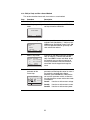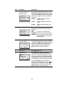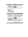
1
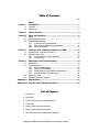
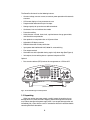
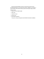
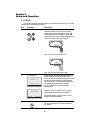
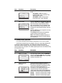
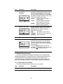
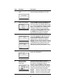
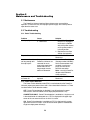
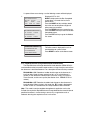
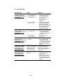
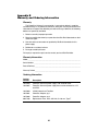
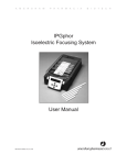
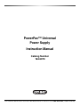
PowerPac™ Universal
Power Supply
Instruction Manual
Catalog Number
164-5070
For Technical Service Call Your Local Bio-Rad Office or in the U.S. Call 1-800-4BIORAD (1-800-424-6723)
Table of Contents
Page
Safety
Section 1
Introduction ................................................................................1
1.1
1.2
Overview.................................................................................................1
Unpacking...............................................................................................2
Section 2
Control Features.........................................................................4
Section 3
Setup and Operation ..................................................................5
3.1
3.2
3.3
Setup ......................................................................................................5
Manual Mode Operation .........................................................................7
Method Mode Operation
3.3.1
Create and Run a New Method .................................................8
3.3.2
Edit (or View) and Run a Saved Method ..................................11
3.3.3
Edit a Paused Run...................................................................13
Section 4
Operation with a Personal Computer and PDA.......................15
4.1
4.2
Operation with a Personal Computer ....................................................15
Operation with a PDA ...........................................................................15
4.2.1
Create, Edit and Transmit Methods..........................................15
4.2.2
Transmit Data..........................................................................17
Section 5
Maintenance and Troubleshooting ..........................................19
5.1
5.2
Maintenance .........................................................................................19
Troubleshooting ....................................................................................19
5.2.1
Basic Troubleshooting .............................................................19
5.2.2
Power Failure Detection...........................................................19
5.2.3
Rapid Resistance Change/No Load Detection .........................20
5.2.4
User Serviceable Error Messages ...........................................21
Replacing a Fuse ..................................................................................23
Expediting Technical Support................................................................23
5.3
5.4
Appendix A Specifications ...........................................................................24
Appendix B Warranty and Ordering Information.........................................25
List of Figures
1. Front View.
2. Rear View.
3. Front View with Legs in Lowered Position.
4. Front Panel.
5. Power Leads Connected Correctly.
6. Power Leads Connected Incorrectly.
7. Rear View Showing Fuse Drawer with Notches.
Copyright © (2003) Bio-Rad Laboratories, Inc. All rights reserved.
Safety
Caution/Warning
!
!
PowerPac power supplies use high output voltages that are electrically isolated from earth
ground to minimize the risk of electrical shock to the user. The following guidelines should
be observed and followed when using a PowerPac power supply.
!
PowerPac power supplies have been tested for operation at temperatures between 0° and
40°C, with relative humidity between 0 and 95% non-condensing. Operating the power
supply outside these conditions is not recommended by Bio-Rad and will void the warranty.
1.
2.
3.
4.
5.
6.
To ensure adequate cooling of the power supply, be sure that there is at least 6 cm
clearance around the power supply. Do not block the fan vent at the rear of the unit.
Always connect the power supply to a 3-prong, grounded AC outlet, using the
3-prong AC power cord provided with the power supply.
Bio-Rad electrophoresis cells have molded two-prong plugs that are inserted into the
power supply’s high voltage output jacks. These plugs have been EN 61010* certified
for safety compliance for use with PowerPac power supplies. Use of other plugs or
banana jacks is done at the user’s own risk and is not recommended by Bio-Rad.
When inserting and removing the molded two-prong plug, always grasp the plug by the
molded support at the rear of the plug. Do not grasp the individual prong ends.
Do not operate the power supply in extreme humidity (>95%) or where
condensation can short the internal electrical circuits of the power supply.
When taking the power supply into a cold room, the unit can be operated immediately.
However, when removing the power supply from the cold room, let the unit equilibrate
to room temperature for a minimum of 2 hours before using it.
Never connect a high voltage output lead to earth ground. This defeats the floating
electrical isolation of the power supply and exposes the user to potentially lethal high
voltages.
Important
This instrument is intended for laboratory use only.
This product conforms to the class A standards for Electromagnetic Emissions, intended for
laboratory equipment applications. It is possible that emissions from this product may
interfere with some sensitive appliances when placed nearby or on the same circuit as
those appliances. The user should be aware of this potential and take appropriate measures
to avoid interference.
Bio-Rad’s PowerPac power supplies are designed and certified to meet EN 61010* safety
standards. Certified products are safe to use when operated in accordance with the
instruction manual. This safety certification does not extend to electrophoresis cells or
accessories that are not EN 61010 certified, even when connected to this power supply.
This instrument should not be modified or altered in any way. Alteration of this instrument
will void the manufacturer’s warranty, void the EN 61010 certification, and create a potential
safety hazard for the user. Bio-Rad is not responsible for any injury or damage caused by
the use of this instrument for purposes other than those for which it is intended, or by
modifications of the instrument not performed by Bio-Rad or an authorized agent.
*EN 61010 is an internationally accepted electrical safety standard for laboratory instruments.
Section 1
Introduction
1.1 Overview
The PowerPac Universal power supply is designed to provide constant voltage,
current or power for a wide range of electrophoresis applications, including high
throughput electrophoresis with the Dodeca cells and electrophoretic blotting.
Output specifications:
Voltage:
Current:
Power:
Output jacks:
Adjustable from 10 to 500 volts (V) in 1 V increments
Adjustable from 10 to 2500 mA in 1 mA increments.
Adjustable from 1 to 500 Watts (W) in 1 W increments.
Four sets of output jacks are provided to facilitate connection
of up to 4 identical electrophoresis cells simultaneously.
1
2 abc
3 def
4 ghi
5 jkl
6 mno
7pqrs
8 tuv
9wxyz
EDIT
0
CE
stop/home
setup
FRONT PANEL
OUTPUT JACKS
Fig. 1. Front view.
Fig. 2. Rear view.
1
The PowerPac Universal has the following features:
•
Constant voltage, constant current, or constant power operation with automatic
crossover
•
LCD screen displays all run parameters at once
•
Programmable methods with up to nine steps
•
Storage capacity for up to nine user defined methods
•
Continuous, hour and volt-hour time modes
•
Paused run editing
•
Safety features: no-load, short circuit, rapid resistance change, ground leak,
and internal thermal protection
•
User optional run completion after an AC power failure
•
Adjustable LCD display contrast
•
EN61010 international safety certification
•
Input power 100-120/220-240 VAC, 50/60 Hz, auto-switching
•
Four output terminals
•
Stackable case with adjustable viewing angle via flip down legs (See Figure 3)
•
Infrared port, for transmitting data to a personal computer or PDA
Optional:
•
Data transfer software (DTS) for data file management on a PDA and PC
LEGS
(LOWERED POSITION)
Fig. 3. Front view with legs in lowered position.
1.2 Unpacking
When you receive your power supply, carefully inspect the container for any
damage which may have occurred in shipping. Severe damage to the container
may indicate damage to the power supply itself. If you suspect damage to the unit,
immediately file a claim with the carrier in accordance with their instructions before
contacting Bio-Rad Laboratories.
2
After unpacking the PowerPac Universal, remove the plastic film from the
translucent green top case. The plastic film may leave a residue. If so, clean with a
soft, damp cloth. Also remove the die-cut plastic film covering the display window.
Contents include:
•
PowerPac Universal power supply
•
Power cord
•
Instruction manual
•
Warranty card
•
Declaration of conformity
If any part is missing or damaged, contact Bio-Rad Laboratories immediately.
3
Section 2
Control features
RUN/PAUSE KEY
ALPHANUMERIC
KEYPAD
STOP/HOME KEY
CLEAR ENTRY KEY
SETUP KEY
IR PORT
SOFT KEYS
EDIT KEY
ARROW KEYS
Fig. 4. Front Panel.
Key
Run/Pause
Description
Starts or pauses a run. When paused, the run parameters for
the current or subsequent step(s) may be edited. The modified
method may be stored to permanent memory by pressing
SAVE at the end of the run.
Stop/Home
Terminates the run in progress and displays the final run
parameters, or if no run is active, changes the display to the
Home screen.
Note: If a method has been edited during a run, SAVE must be
pressed at the end of the run to save the changes.
Setup
Used to set the PowerPac Universal default settings such as:
power failure detection, rapid resistance change detection, no
load detection as well as clock, contrast and key chirp settings
(see Section 3.1).
EDIT
Toggles soft key assignments between those used to set the
run mode (constant voltage, constant current or constant
power), run limits (voltage, current or power) and time mode
(hours, volt-hours or untimed).
Arrow Keys
Used to scroll through method list or method protocol. An
asterisk (*) is used to identify the selected method or step.
CE
Deletes alphanumeric characters from a parameter value or
method name, or restores previous numeric value.
CE
Alpha-numeric
keypad
Soft Keys
Used to enter parameter values and method names. When
method names are entered, the manner in which keys are
pressed determines the characters entered and their placement.
Rapid repetitive strokes on a single key cause the character
displayed at the cursor position to toggle between those
associated with the key (i.e. a→b→c→2→A→B→C→2). The
cursor position advances each time a different key is pressed
or when there is a pause between strokes of a single key.
The commands on the LCD screen immediately above the soft
keys assign their functionality.
4
Section 3
Setup and Operation
3.1 SET UP
This section describes how the PowerPac Universal power supply is set up and
connects to an electrophoresis cell(s).
Step
1.
Procedure
Connect Cells
Description
Insert power leads into one of the output
terminals located on the front of the power
supply (shown to the left). Note that the
symbol indicates high voltages and that
the power leads must be inserted perpendicular
to the curve of the case (see Figure 5).
Universal
Fig. 5. Power Lead Connected Correctly
Universal
Fig. 6. Power Leads Connected Incorrectly
2.
Turn power on
FW Version: 1.20
Serial No. 000002
SELECT MODE
MANUAL
3.
METHODS
Open the setup editor
Use the switch located on the right side of the
power supply to turn the power on. When
turned on, the unit briefly displays the firmware
version and serial number and then goes to
the Home screen. The Home screen soft keys
are used to operate the power supply in
manual (Section 3.2) or method mode
(Section 3.3).
MANUAL mode: Program and run a single
step method without storing into memory.
METHODS mode: Program, store, and run
single or multistep methods.
Press SETUP to start the setup editor. SETUP
can be pressed from any screen except the
run screen.
5
Step
4.
Procedure
Set the Power Failure
detection mode
SETUP
PFd: OFF
RRCd-NLDd: ON
PFd
5.
RRCd-NLDd
PANEL
Set the Rapid
Resistance Change
detection/No Load
detection mode
SETUP
PFd: OFF
RRCd-NLDd: ON
PFd
RRCd-NLDd
PANEL
Description
Use the PFd soft key to set the Power Failure
detection mode:
PFd = OFF: Turns power failure detection
off. In this mode, the run is terminated if
a power failure occurs.
PFd = ON NEXT RUN ONLY: Turns
power failure detection on for a single
run.
PFd = ON: Turns power failure detection
mode on. If there is a power failure in
this mode, then the run will resume when
the power is restored after single or
mulitple power failures.
Warning: Turning the power supply off to stop
a run in progress is regarded as a power failure
and the interrupted run (when PFd = ON) will
resume the next time the power supply is
turned ON.
Press the RRCd-NLDd soft key to change the
Rapid Change detection and No Load
detection mode.
RRCd-NLDd = ON: Detection of a load
change greater than 20% or 15 mA, or
the absence of a load (current is less
than 2 mA), will cause an alarm to sound
and the run to pause.
RRCd-NLDd = OFF: Does not detect
sudden load changes or the absence of
a load. When running in this mode, the
!
!
symbol
is displayed on the Run
screen as a reminder that this safety
feature has been turned off.
Note: This mode is used to complete
electrophoresis application such as the D-Code
that require that Rapid Resistance Change
detection be turned off or applications such as
isoelectric focusing that require less than 2 mA
current.
6.
Set the control panel
default settings
Press the PANEL soft key.
7.
Set the default contrast
Press the CONTRAST soft key and enter a
value from the keypad. The contrast value
range is between 80 and 110.
Tue
27-May-03
11:22
CONTRAST: 95
KEY CHIRP: ON
CLOCK CONTRAST CHIRP
6
Step
8.
Procedure
Set the key chirp mode
Tue
27-May-03
11:22
CONTRAST: 95
KEY CHIRP: ON
CLOCK CONTRAST CHIRP
9.
Set the clock
27-May-03
Tue
11:22
CHANGE DAY W/ARROWS.
CONTRAST: 95
KEY CHIRP: ON
PREV
NEXT
SET
Description
Press the CHIRP soft key to turn key chirp on
or off.
KEY CHIRP = OFF: No sound is
produced when a key is pressed. This
does not affect alarms.
KEY CHIRP = ON: A chirp noise is
heard every time a key is pressed.
Press the CLOCK soft key to display the clock
settings screen. Use the PREV and NEXT soft
keys to move the cursor between the day,
date and time fields. The up and down arrow
keys are used to set the day and month and
the keypad is used to enter the date and time
values.
Press the SET soft key to accept the new day,
date and time values.
Press Setup once to return to the previous
screen or twice to exit setup mode.
Note: The PowerPac Universal contains an
internal battery to maintain the clock settings
during power off.
3.2 Manual Mode Operation
This section describes how to program and perform a run in manual mode.
In the Manual mode the user can program and start a single step method with
a minimum number of keystrokes. This single step method is not stored in
permanent memory; however, the run parameters are kept in the flash memory
until the PowerPac is turned off. This allows repeating the same run without having
to re-enter the values.
Step
1.
Procedure
Set up the power supply
Description
Refer to Section 3.1 for instrument setup.
2.
Select a run mode
From the Home screen, press the MANUAL
soft key to perform a single step run in manual
mode or press METHODS to run a multi-step
method (see Section 3.3).
SELECT MODE
MANUAL
3.
METHODS
Select a constant
parameter
EDIT CONSTANT
0V
2500 mA
500 W
TIME: UNTIMED
CONSTV CONSTA CONSTW
Use the soft keys to select the constant
parameter and the keypad to enter its value.
The constant parameter is displayed in large
font. If the run will be performed as an
un-timed run at the displayed maximum limit
values for the non-constant parameters
(shown to the right of the constant parameter)
skip to Step 6, otherwise press the EDIT key.
ConstV: Used to run with constant voltage.
ConstA: Used to run with constant current.
ConstW: Used to run with constant power.
7
Step
4.
Procedure
Enter limits for the
non-constant
parameters
EDIT LIMITS
100 V
2500 mA
500 W
TIME: UNTIMED
CONSTV LIMITA
5.
LIMITW
Select the time mode
EDIT TIME
100 V
2500 mA
500 W
TIME: 00:00 HRS
HRS
VHOURS
UNTIMED
Description
Use the soft keys to select a non-constant
parameter and the keypad to enter its value.
If the run will be performed as an un-timed
run, skip to Step 6, otherwise, press the EDIT
key. Note: to change the constant value, press
its soft key and enter a new value.
ConstV: Used to change the voltage
constant value.
LimitA:
Used to change the maximum
default value for current limit.
LimitW:
Used to change the maximum
default value for power limit.
Use the soft keys to select the time mode and
the keypad to enter the run time. Press the
EDIT key to return to Step 3, otherwise,
proceed to the next step.
HRS:
Run time is in units of hours.
VHOURS: Run time is in units of volt-hours.
UNTIMED: Run is continuous.
6.
Start the run
Press
7.
Monitor the run
The run screen is used to monitor run
parameters or to pause a run. The elapsed
time versus the programmed time, voltage,
current and power values may be viewed from
the run screen.
Press the PAUSE soft key to edit the run
parameters (see Section 3.3.3) or to abort the
run. Press
to terminate the run.
RUN
100 V
52 mA
5 W
00:00/01:00 HRS
PAUSE
to start a run.
3.3 Method Mode Operation
This section describes how to program and perform a run in Method mode.
Method mode operation is used to create and run single and multi-step methods.
In method mode, up to nine methods, each with up to nine steps may be
programmed, stored, or edited. Each of these methods may be transferred to or
from a PDA, through the PowerPac Universal IR port as described in Section 4.
3.3.1 Create and Run a New Method
This section describes how to create and run a new method.
Step
Procedure
Description
1.
Setup the power supply
Refer to Section 3.1 for instrument setup.
8
Step
2.
Procedure
Select the programming
mode
Description
On the Home screen, press the METHODS
soft key to display the Method List screen.
SELECT MODE
MANUAL
3.
METHODS
Create a new method
METHOD LIST
...EMPTY 1...
...EMPTY 2...
...EMPTY 3...
OPEN
4.
DELETE
NEW
Name the new run
Press the up arrow key to select the method
name field. Note that the soft keys have now
changed to CANCEL and OK. Use the CE
button to delete the default name and the
keypad to enter a method name. Refer to
Section 2 for help using the keypad. Press the
CANCEL soft key to abort naming the method
or the OK soft key to accept the new name.
Note that OK accepts the name but is not
stored into memory until the method is saved.
METHOD: UNTITLED
*
S1
(EMPTY)
METHODS
EDIT NAME: NAME_
S1
(EMPTY)
CANCEL
5.
Press the NEW soft key on the Methods List
screen to create a new method. Note that if
there are already nine methods defined in the
list, an existing method will need to be deleted
before a new method can be added to the list.
To delete a method use the up and down
arrow keys to select a method (identified by *)
and then press the DELETE soft key. Press
the OPEN soft key to open the selected,
stored method and display the method.
OK
Select a step to edit
Press the EDIT key to open the selected
empty step (identified by *).
METHOD: NAME
*
S1
(EMPTY)
METHODS
6.
DELETE
SAVE
Set the constant
parameter for the
current step
S1/1 EDIT CONSTANT
0V
2500 mA
500 W
Use the soft keys to select the constant
parameter and the keypad to enter its value. If
the method is complete go to Step 10,
otherwise, press the EDIT key. Note that the
maximum default values for the non-constant
parameters are listed on the right side of the
screen and the time mode at the bottom.
TIME: UNTIMED
CONSTV CONSTA CONSTW
ConstV:
ConstA:
ConstW:
9
Used to run with constant voltage.
Used to run with constant current.
Used to run with constant power.
Step
7.
Procedure
Enter non-constant
parameter limits for
the current step
S1/1 EDIT LIMITS
2500 mA
100 V
500 W
TIME: UNTIMED
CONSTV
Description
Use the soft keys to select a non-constant
parameter and the keypad to enter its value.
If the method is complete and will be run
un-timed go to Step 10, otherwise, press the
EDIT key. Note: to change the constant value,
press its soft key and enter a new value.
ConstV:
LIMITW
LIMITA
LimitA:
LimitW:
8.
Select the time mode
S1/1 EDIT TIME
100 V
2500 mA
500 W
TIME: UNTIMED
HRS
9.
UNTIMED
VHOURS
Add a new step or save
the method
Used to change the voltage
constant value.
Used to change the maximum
default value for current limit.
Used to change the maximum
default value for power limit.
Use the soft keys to select a time mode and
the keypad to enter the run time. Press EDIT.
HRS:
Run time is in units of hours.
VHOURS: Run time is in units of volt-hours.
UNTIMED: Run is continuous. Note that steps
programmed after an un-timed
step are ignored.
To program additional steps press the down
arrow key to select the empty step and repeat
steps 5–8.
METHOD: NAME
*
S1
100V 00:30 HRS
S2
(EMPTY)
METHODS
DELETE
SAVE
If the method will not be saved, go directly to
Step 10, otherwise press the SAVE soft key
and then go to Step 10. Press the DELETE
soft key to delete the selected step. Press the
METHODS soft key to return to the Method
List screen.
10.
Start the run
Press
11.
Monitor the run
The run screen is used to monitor run
parameters or to pause a run. The current
step versus total steps programmed, voltage,
current and power values, elapsed time versus
the programmed time, and total elapsed time
of the method are displayed on the run screen.
RUN: S1/2
100 V
00:00/00:30
53 mA
5 W
00:00 HRS
PAUSE
12.
View the run
information
RUN COMPLETED AT:
05/27/03
12:34:01
200V
106mA
Time:
RERUN
00:01
Vh:
21W
00003
EXIT
to start a run.
Press the PAUSE soft key to edit the run
parameters (see Section 3.3.3). Press
to
terminate the run. Note that any edits
made during the run will not be saved unless
SAVE is pressed at the end of the run.
The "Run Completed" or "Run Terminated"
screen is displayed at the end of a run. The
date and time, the final running parameter
values, the total elapsed time in hours and
volt-hours are displayed on the screen. Press
the RERUN soft key to repeat the run or the
EXIT soft key to display the Method Step List.
After the run is finished, the run data may be
transmitted to a PDA or PC (see Section 4.2.2).
10
3.3.2 Edit (or View) and Run a Saved Method
This section describes how to edit, view and run a saved method.
Step
1.
Procedure
Set up the power supply
Description
Refer to sections 3.1 for instrument setup.
2.
Select the programming
mode
On the Home screen, press the METHODS
soft key to view the method list.
SELECT MODE
MANUAL
3.
METHODS
Open an existing method Use the up and down arrow keys to select a
method to edit (identified by *) and then press
OPEN to open the Method screen. Press
METHOD LIST
to run the opened method or go to Step 4 to
IEF
* NATIVE
view and edit the method.
SDS-PAGE
OPEN
4.
DELETE
NEW
Select a step to edit
METHOD: SDS-PAGE
*
S1
100V 00:30 HRS
S2
300V 00:30 HRS
S3
METHODS
5.
(EMPTY)
DELETE
Set the constant
parameter for the
current step
S1/2 EDIT CONSTANT
100 V
2500 mA
500 W
TIME: 00:30 HRS
CONSTV CONSTA CONSTW
Press the up and down arrow keys to select a
step. An asterisk (*) indicates the selected
step. Press EDIT to view or edit. Note: to edit
the method name, use the up arrow key to
move to the method name and activate the
name field. Use the keypad to change the
name.
Use the soft keys to select the constant
parameter and the keypad to enter its value. If
the method is complete skip to Step 9,
otherwise, press the EDIT key. Note that the
non-constant parameter values are listed on
the right side of the screen and the time mode
at the bottom.
ConstV: Used to run with constant voltage.
ConstA: Used to run with constant current.
ConstW: Used to run with constant power.
11
Step
6.
Procedure
Set the non-constant
parameter limits for
the current step
S1/2 EDIT LIMITS
100 V
2500 mA
500 W
TIME: 00:30 HRS
CONSTV
7.
LIMITA
LIMITW
Select the time mode
S1/2 EDIT TIME
100 V
2500 mA
500 W
TIME: 00:30 HRS
HRS
8.
UNTIMED
VHOURS
Add a new step or
save the method
METHOD: SDS-PAGE
*
S1
100V 00:30 HRS
S2
300V 00:30 HRS
S3
METHODS
Description
Use the soft keys to select a non-constant
parameter and the keypad to enter its value.
If the method is complete skip to Step 9, otherwise, press the EDIT key. Note: to change the
constant value, press its soft key and enter a
new value.
ConstV: Used to change the voltage
constant value.
LimitA:
Used to change the current limit
value.
LimitW:
Used to change the power limit
value.
Use the soft keys to select a time mode and
the keypad to enter the run time. Press the
EDIT key.
HRS:
Run time is in units of hours.
VHOURS: Run time is in units of volt-hours.
UNTIMED: Run is continuous. Note that steps
programmed after an un-timed
step are ignored.
If more steps are to be added to the method,
use the down arrow key to move to the empty
step, press the EDIT key and repeat steps 5–8
to add a new step. If the method will not be
saved, go to Step 9, otherwise press the
SAVE soft key and then go to Step 9.
(EMPTY)
DELETE
SAVE
9.
Start the run
Press
10.
Monitor the run
The run screen is used to monitor run
parameters or to pause a run. The current
step versus total steps programmed, voltage,
current and power values, elapsed time versus
the programmed time, and total elapsed time
of the method are displayed on the run screen.
RUN: S1/2
100 V
00:00/00:30
53 mA
5 W
00:00 HRS
to start a run.
PAUSE
Press the PAUSE soft key to edit the run
parameters (see Section 3.3.3). Press
to
terminate the run. Note that any edits
made during the run will not be saved unless
SAVE is pressed at the end of the run.
12
Step
11.
Procedure
View the run
information
RUN COMPLETED AT:
05/27/03
12:34:01
200V
106mA
Time:
00:01
21W
Vh:
00003
RERUN
EXIT
Description
The "Run Completed" or "Run Terminated"
screen is displayed at the end of a run. The
date and time, the final running parameter
values, the total elapsed time in hours and
volt-hours are displayed on the screen. Press
the RERUN soft key to repeat the run or the
EXIT soft key to display the Method Step List.
After the run is finished, the run data may be
transmitted to a PDA or PC (see Section 4.2.2).
3.3.3 Edit a Paused Run
This section describes how to edit a paused run.
Step
Procedure
Description
1.
Pause the run
Press the PAUSE soft key or
run that is in progress.
to pause a
RUN: S1/2
53 mA
100 V
00:00/00:30
5 W
00:00 HRS
PAUSE
2.
Edit the method
The pause window displays the current run
parameters as well as the date and time that
the run was paused.
RUN PAUSED AT:
05/27/03
12:29:00
100V
53mA
Time:
00:00
EDIT
3.
5W
Vh:
00000
CONTINUE
Select a method step
METHOD: SDS-PAGE
*
S1
100V 00:30 HRS
S2
300V 00:30 HRS
S3
(EMPTY)
CONTINUE
4.
Set the constant
parameter for the
current step
S1/2 EDIT CONSTANT
100 V
2500 mA
500 W
TIME: 00:30 HRS
CONSTV CONSTA CONSTW
Press the EDIT soft key or the EDIT key to
modify the method. The CONTINUE soft key
or
button can be used to resume the run.
Press the up and down arrow keys to select
the step to edit or add. An asterisk (*) indicates
the selected step.
Press the EDIT key to modify the selected
step.
Press the CONTINUE soft key or
to
resume the run when finished editing the
method.
Use the soft keys to select the constant
parameter and the keypad to enter its value.
Press the EDIT key when finished. The
key can be pressed at any time to resume the
run. Note that the non-constant parameter
values are listed on the right side of the screen
and the time mode at the bottom.
ConstV: Used to run with constant voltage.
ConstA: Used to run with constant current.
ConstW: Used to run with constant power.
13
Step
5.
Procedure
Set the non-constant
parameter limits for
the current step
S1/2 EDIT LIMITS
100 V
2500 mA
500 W
TIME: 00:30 HRS
CONSTV
6.
LIMITA
LIMITW
Select the time mode
S1/2 EDIT TIME
100 V
2500 mA
500 W
TIME: 00:30 HRS
7.
Exit the run completed
screen
RUN COMPLETED AT:
05/27/03
12:34:01
200V
106mA
Time:
00:01
Vh:
21W
00003
RERUN
8.
EXIT
Save the changes
METHOD: SDS-PAGE
*
S1
100V 00:30 HRS
S2
300V 00:30 HRS
S3
METHODS
Description
Use the soft keys to select a non-constant
parameter and the keypad to enter its value.
Press the EDIT key when finished. The
key can be pressed at any time to resume the
run. Note: to change the constant value, press
its soft key and enter a new value.
ConstV: Used to change the voltage
constant value.
LimitA:
Used to change the current limit
value.
LimitW:
Used to change the power limit
value.
Use the soft keys to select a time mode and
the keypad to enter the run time. Press the
EDIT key when finished and go to Step 3. The
key can be pressed at any time to resume
the run. Note that the time mode cannot be
changed for the step in progress.
HRS:
Run time is in units of hours.
VHOURS: Run time is in units of volt-hours.
UNTIMED: Run is continuous. Note that steps
programmed after an un-timed
step are ignored.
After the run is finished the "Run Terminated"
or "Run Completed" screen is displayed. At
this point the run data may be transmitted to a
PDA or PC, if desired (see Section 4.2.2).
Press the RERUN soft key to repeat the run or
the EXIT soft key to return to the Method Step
List screen.
From the Method Step List screen, press the
SAVE soft key to save the changes made
during the run. Note that pressing SAVE will
overwrite the original method.
(EMPTY)
DELETE
SAVE
14
Section 4
Operation with a Personal Computer and PDA
The PowerPac Universal is capable of transmitting methods to and from a
PDA, and transmitting run data to a personal computer (PC) or PDA through the IR
port located on the front of the power supply.
4.1 Operation with a Personal Computer
Communication between a PowerPac Universal power supply and a PC
requires that the PowerPac data transfer software (Catalog Number 164-5067,
includes PowerPac remote software also) be installed on a compatible PC. The
PowerPac data transfer software for the PC is compatible with computers that run
the Windows 2000™ or Windows XP™ operating system and that include an IrDA
port. The PowerPac data transfer software is used to transmit run data from the
PowerPac Universal or PDA, to a PC. PowerPac data transfer software
instructions are contained within the help file of the software itself and will not be
discussed here.
4.2 Operation with a PDA
Communication between a PowerPac Universal power supply and a PDA
requires that the PowerPac remote software (Catalog Number 164-5067, includes
PC software also) be installed on a compatible PDA. The PowerPac remote
software is compatible with any PDA that runs Palm OS version 4.0 or above. With
the PowerPac remote software the PDA can perform the following functions:
•
•
•
•
•
•
Transmit methods to and from the PowerPac Universal.
Receive data from the PowerPac Universal
Transmit data to a PC
Create and store up to 20 methods
Store up to 20 data files
Provide unique data file identification
Instructions for the PowerPac remote software for PDA operation are given in
the following two sections.
4.2.1 Create, Edit and Transmit Methods
Step
1.
Procedure
Start the software
Description
Start the PowerPac Remote software and
press Select/Edit Methods….
Bio-Rad Laboratories
PowerPac Remote Control
Select/Edit Methods...
Run Data
15
Step
2.
Procedure
Open a method
Existing Methods
Edit
Sample
Beam
New Method
Purge Methods
Beam Current Method In
3.
Done
Edit the method
Method: SDS-PAGE
Rename
Description
There are three ways to open a method:
a.
Press New Method to create and open a
new method.
b.
Select a method from the drop-down
method list and press Edit. Note that the
Edit and Beam buttons appear only if a
method from the method list has been
selected.
c.
Press Beam Current Method In to
retrieve a method from the PowerPac
Universal and store it in the method list.
Note: the method in the PowerPac
Universal has to be opened before
transmission.
Other Buttons
Purge Methods: Used to delete ALL
methods stored on the PDA
Beam: Transmits the currently selected
method to the PowerPac Universal
Done: Returns to the start-up screen.
Press Select/Edit Methods..., select the
method from the drop-down method list and
press Edit.
Save
Delete
Beam
Select a step to edit from the Method Steps
drop-down menu.
Method Steps
S 1 100V 2500mA 500W UNTIMED
S 2 ---Blank Step---
Delete Step
Methods
16
Step
4.
Procedure
Edit a step
Save
Method: SDS-PAGE
Delete
Rename
Beam
Step # 1
Const Mode
V Timing
T
A
W
Vh
Volts: 100
mAmps: 2500
Watts: 500
Vhours: 00000
Untimed
Delete Step
5.
Methods
Transmit the method
Description
a.
Set the Constant mode: voltage (V), current (A) or power (W).
b.
Enter the constant and non-constant
values in the Volts, mAmps and Watts
fields.
c.
Select whether the run will be timed
(Untimed box is not checked) or
un-timed (the Untimed box is checked).
d.
Change the method name as needed.
Check the Rename box to rename the
method or leave it un-checked to save
the edited method with the new name.
e.
Select another step to edit from the
"Step" drop-down list and edit the step.
f.
Press Save to save the method.
Other Buttons
Delete: Deletes the entire method.
Delete Step: Deletes the current step.
Methods: Returns to Method List screen.
Press Beam to transmit the method to the
PowerPac Universal. Note that if nine
methods already exist on the PowerPac
Universal that the new method will be
transmitted to flash memory so it can be run,
but it will not be saved to the method list.
4.2.2 Receive and Transmit Data
Step
1.
Procedure
Start the software
Description
Start the PowerPac Remote software and
press Run Data
Bio-Rad Laboratories
PowerPac Remote Control
Select/Edit Methods...
Run Data
17
Step
2.
Procedure
Receive data from the
PowerPac Universal
Collected Run Data
Run Data
Description
Press Get Data From PowerPac to request
and receive the data file from the PowerPac’s
most recent run.
Other Buttons
Purge Data: Used to delete ALL data stored
on the PDA
Done: Returns to the start-up screen.
Purge Data
Get Data From PowerPac
Done
3.
Transmit data to a PC
Collected Run Data
This data file has not been
beamed to the PC
SN 00002 15:56:05 27-May-03
Purge Data
Extract Method
Get Data From PowerPac
Beam
Delete
Done
Select a data file from the drop-down Run
Data list and then press Beam to transmit the
data to a PC. The warning "This data file has
not been beamed to the PC" is displayed for
all data files that have not been transmitted to
a PC. Note that the Extract Method, Beam
and Delete buttons appear only if a run in the
Run Data list has been selected.
Other Buttons
Purge Data: Used to delete ALL data stored
on the PDA
Extract Method: Displays the method that
was used to create the selected run data.
Beam: Transmits data to a PC
Delete: Deletes the currently selected data
file.
Done: Returns to the start-up screen.
18
Section 5
Maintenance and Troubleshooting
5.1 Maintenance
The PowerPac Universal requires little maintenance to assure reliable
operation. To clean the case, first unplug the power supply. Use a damp cloth to
wipe down the outer case.
5.2 Troubleshooting
5.2.1 Basic Troubleshooting
Problem
No display/lights/fan
Cause
1. No AC power.
2. Blown fuse
Repeated blown fuses
Hardware failure
Leads from the cell are Output terminals for the
not long enough to fit
PowerPac Universal are
the output jacks
recessed 16 mm to
meet safety regulations.
Some leads are not
long enough to make
electrical connection.
Clock loses settings
on Power Off
Onboard battery
depleted
Solution
1. Check if the PowerPac
Universal is unplugged,
or if there is a problem
with th AC power source,
or if the power switch is
in the off position.
2. Replace the fuse. See
Section 5.3 for details.
Contact Bio-Rad Technical
Resources.
Use the PowerPac Adaptor
(Catalog number 165-5061),
which accommodates most
standard 4 mm banana
plugs, to make secure
electrical connection.
Note: use of this PowerPac
adaptor voids EN61010
safety provisions.
Contact Bio-Rad Technical
Resources
5.2.2 Power Failure Detection
The Power Failure detection mode (PFd) is used to determine the PowerPac
Universal response to power failures and is set as described in Section 3.1. There
are three Power Failure detection modes:
OFF: Power Failure detection is disabled. A run will terminate if a power
failure occurs and Error code 07 will be displayed (see Section 5.2.4).
ON NEXT RUN ONLY: Power Failure detection is enabled for a single run and
is then disabled for all subsequent runs. "PFd" is displayed in the upper right
corner of the run screen for the run in which it is active.
ON: Power Failure detection is enabled and "PFd" is displayed in the upper
right corner of the run screen. A run will resume when power is restored after
single or multiple power failures(s).
19
If a power failure occurs during a run the following screens will be displayed.
1.
RUN COMPLETED AT:
05/27/03
12:35:56
200V
105mA
Time:
RERUN
00:01
21W
Vh:
00002
MORE
EXIT
AC POWER INTERRUPTED
AT: 05/27/03
12:35:00
RESTARTED RUN
AT: 05/27/03
RERUN
2.
12:35:07
BACK
EXIT
ERROR STOP: CODE 07
RUN POWER FAILURE
RUN TERMINATED.
Displayed if PFd = ON
MORE is displayed on the Run Completed
screen when a run ends that has had a
power failure.
Press the MORE soft key to display details
about the most recent power outage and
when power was restored.
Press the RERUN soft key to restart the run
Press the BACK soft key to return to the Run
Completed screen.
Press the EXIT soft key to go to the Method
List screen
Displayed if PFd = OFF
This error screen is displayed if a run has
terminated due to a power failure.
Press RESET to return to the Home screen
RESET WHEN READY.
RESET
5.2.3 Rapid Resistance Change Detection/No Load Detection
The Rapid Resistance Change detection/No Load detection (RRCd-NLDd) is
used to determine the instruments response due to a large change in resistance or
the absence of a load. See Section 3.1 for a description of how to set this parameter.
RRCd-NLDd = ON: Detection of sudden load changes or the absence of a
load is enabled. Load changes greater than 20% or 15 mA (whichever is
greater), or the absence of a load (current is less than 2 mA), will cause an
alarm to sound, and the run to pause (See Section 5.2.4, ERROR STOP 01
and 09).
RRCd-NLDd = OFF: Detection of sudden load changes or the absence of a
! is displayed on
load is disabled. When running in this mode, the ! symbol
the Run screen as a reminder that this safety feature has been turned off.
!
Note: This mode is used to complete electrophoresis application such as the
D-Code that require that Rapid Resistance Change detection be turned off (due to
possible fluctuations in current during a normal run), or applications such as
isoelectric focusing that require less than 2 mA current.
20
5.2.4 Error Messages
Error Message
Cause
Solution
ERROR STOP CODE 01
1. Electrophoresis cell
NOLOAD DETECTED
not connected to the
CORRECT AND CONTINUE
power supply or
RUN PAUSED
buffer levels too low.
CONTINUE CANCEL
2. The current load is
less than 2 mA.
1. Make sure all electrical
connections make good
contact and the cables
and wire electrodes are
in good shape.
Verify buffer levels are
appropriate.
2. Verify the electrophoresis
application power requirements match PowerPac
Universal output range. Note:
The No Load detection can
be de-activated. (See
Sections 3.1 and 5.2.3)
ERROR STOP: CODE 02
1. Accidental shorting
OVER CURRENT
of output leads.
CORRECT AND CONTINUE
RUN PAUSED
CONTINUE CANCEL
2. Shorting due to
wrong connections.
1. Make sure all electrical
connections make good
contact and the cables
and wire electrodes are in
good shape.
2. Verify buffer levels are
appropriate.
ERROR STOP: CODE 03
1. Control circuitry
OVER VOLTAGE
problem
CORRECT AND CONTINUE
RUN PAUSED
CONTINUE
CANCEL
1. Press the CONTINUE soft
key to continue the run.
If the problem continues,
cycle power and restart the
run. If the problem persists,
contact Bio-Rad Technical
Support.
ERROR STOP: CODE 07
RUN POWER FAILURE
RUN TERMINATED
RESET WHEN READY
RESET
AC Power was interrupted
during the run and the
run was terminated
because the Power
failure detection is OFF
To continue a run after a
power failure, activate the
Power Failure Detection mode
in the Setup window (See
Section 3.1).
ERROR STOP: CODE 08
REGULATION ERROR
RUN TERMINATED
RESET WHEN READY
RESET
Control circuitry
problems.
1. Press the RESET soft key to
clear the screen, then
restart the run.
2. If the problem continues,
cycle power and restart the
run. If the problem persists,
contact Bio-Rad Technical
support.
21
Error Message
Cause
Solution
ERROR STOP: CODE 09
1. Loose output
RAPID CHANGE IN R
connections leading
CORRECT AND CONTINUE
to intermittent
RUN PAUSED
connection to the
CONTINUE CANCEL
loads.
2. Cells added or
removed during
the run.
3. Change in buffer
levels
1. Verify all electrical
connections.
2. Pause power supply prior
to adding or removing
electrophoresis cells
3. Verify buffer levels are
appropriate.
Note: certain applications
exhibit intrinsic fluctuations in
resistance (e.g. Dcode). If this is
the case, the change in resistance detection feature can be
disabled to allow uninterrupted
completion of the run. (See
Sections 3.1 and 5.2.3).
1. Check electrical connections,
electrophoresis cell, and
chiller system for leaks.
Verify that the electrophoresis
cell rests on an insulated
and dry surface.
2. Check Power source
connections. Additional
capacitance to ground from
external EMC filters or a UPS
(Uninterruptible Power
Supply) can cause
excessive ground currents.
ERROR STOP: CODE 11
GROUND LEAK
CORRECT AND CONTINUE
RUN PAUSED
CONTINUE CANCEL
Insulation failure in the
electrical connections
made outside the power
supply has caused a
current flow that may
create an unsafe
condition.
ERROR STOP: CODE 12
REGULATION ERROR
RUN TERMINATED
RESET WHEN READY
RESET
Improper load, or
connection to a
voltage source
1. Press Reset and restart the
run.
2. If the problem continues,
cycle power and restart the
run. If the problem persists,
contact Bio-Rad Technical
support.
ERROR STOP: CODE 13
PERM MEM ERROR
Internal circuitry
problems
Cycle power and restart run.
If problem persists, contact
Bio-Rad Technical support.
22
5.3 Replacing a Fuse
If the power supply is plugged into a working outlet, with the power switch in
the ON position and there is no display, lights or fan operation, a fuse might need
to be replaced.
1. Disconnect the power cord from the electrical outlet.
2. Use a fingernail or a flat blade screwdriver to gently press the tabs on the side
of the fuse holder toward each other. This will release the fuse holder and the
fuses. See Figure 7. Inspect the fuses visually to determine if one or both of the
fuses are blown.
3. Remove the blown fuse from the fuse holder. Replace it with a 6.3A, 250VAC
5mm X 20mm fuse (Bio-Rad part number 900-7288).
4. Re-insert the fuse holder into its position. Press the fuse holder gently until it
snaps into place on both sides.
The unit is now ready for use.
FUSE
DRAWER
NOTCHES
Fig. 7. Rear view Showing Fuse Drawer with Notches.
Note: Repeated blowing of the fuse indicates a hardware failure. Contact Bio-Rad
Technical Support.
5.4 Expediting Technical Support
Make sure the following information is readily available before contacting Bio-Rad.
Product model no: Located in the sticker on the bottom of the unit
(example: PowerPac Universal Power Supply).
Serial number: Located in the sticker on the bottom of the unit
Software version: The PowerPac Universal displays the software version
momentarily after switching the power ON (example: Firmware 1.20).
State clearly the error code, error message or anomaly, and the conditions that
originated the problem, including run parameters (V, A, and W) as well as the
electrophoresis cell and buffer system.
23
Appendix A
Specifications
Output specifications:
Output range (programmable):
Type of output:
Output terminals
Timing mode
Pause/resume function:
Display:
Operating Conditions:
Safety compliance:
EMI:
Safety features:
Input protection:
Input power(nomial)
Dimensions:
Weight:
500 V, 2500 mA, 500 W
10–500 V, fully adjustable in 1 V increments
10–2500 mA, fully adjustable in 1 mA
increments
1–500 W, fully adjustable in 1 W increments
Constant voltage, current, or power with
automatic crossover
Four pair of recessed banana jacks in
parallel
Continuous, timed to 99:59Hrs, or
99999 volt-hours.
Yes
128 x 64 Monochrome Backlit LCD
0–40°C; 0–95% humidity in the absence of
condensation
EN61010
Conforms to CE Standards for emissions and
immunity class A.
No load detection; sudden load change
detection; ground leak detection;
overload/short circuit detection; overvoltage
protection; overheating protection
Fuse on hot and neutral
100–120/220–240 VAC, 50/60 Hz
auto-switching
27.5cm X 9.8cm X 34.5 cm
2.5 kg
24
Appendix B
Warranty and Ordering Information
Warranty
The PowerPac Universal is warranted for 1 year against defects in materials
and workmanship. If any defects should occur during this warranty period, Bio-Rad
Laboratories will replace the defective parts without charge. However, the following
defects are specifically excluded:
1. Defects caused by improper operation.
2. Repair or modification done by anyone other than Bio-Rad Laboratories or their
authorized agent.
3. Use with cables or connectors not specified by Bio-Rad Laboratories for this
power supply.
4. Deliberate or accidental misuse.
5. Damage caused by disaster.
For inquiry or request for repair service, contact your local Bio-Rad office.
Warranty Information
Model:___________________________________________________________
Serial Number: ____________________________________________________
Date of Delivery: ___________________________________________________
Warranty Period: ___________________________________________________
Ordering Information
Catalog
Number
Description
164-5070
PowerPac Universal power supply, 100–120/220–240V
164-5067
PowerPac Universal power supply data transfer software for a PC
and PDA
164-5069
IQ/OQ Protocol and Test Box
165-5061
PowerPac Adaptor, qty 1
165-5066
PowerPac Adaptor, qty 2
900-7288
Replacement Fuse, 6.3 A, 250 VAc, 5 x 20 mm, Type T
25
Bio-Rad
Laboratories, Inc.
Web site www.bio-rad.com USA (800) 4BIORAD Australia 02 9914 2800 Austria (01)-877 89 01 Belgium 09-385 55 11 Brazil 55 21 2527 3454
Canada (905) 712-2771 China (86-21) 63052255 Czech Republic + 420 2 41 43 05 32 Denmark 44 52 10 00 Finland 09 804 22 00
France 01 47 95 69 65 Germany 089 318 84-0 Hong Kong 852-2789-3300 Hungary 36 1 455 8800 India (91-124)-6398112/113/114, 6450092/93
Israel 03 951 4127 Italy 39 02 216091 Japan 03-5811-6270 Korea 82-2-3473-4460 Latin America 305-894-5950 Mexico 55-52-00-05-20
The Netherlands 0318-540666 New Zealand 64 9 415 2280 Norway 23 38 41 30 Poland + 48 22 331 99 99 Portugal 351-21-472-7700
Russia 7 095 721 1404 Singapore 65-6415 3188 South Africa 00 27 11 4428508 Spain 34 91 590 5200 Sweden 08 555 12700
Switzerland 061 717-9555 Taiwan (8862) 2578-7189/2578-7241 United Kingdom 020 8328 2000
Life Science
Group
Bulletin 3085
US/EG
Rev A
0104
Sig 1103
4006223 Rev B