1
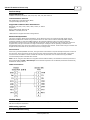
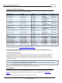
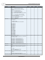
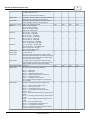
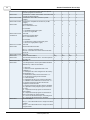
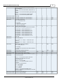
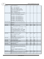
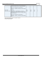
Simatic/TI 505 Serial
Driver Help
© 2012 Kepware Technologies
Simatic/TI 505 Serial Driver Help
2
Table of Contents
Table of Contents
2
Simatic/TI 505 Serial Driver Help
3
Overview
3
Device Setup
4
Modem Setup
4
Addressing Options
4
Data Types Description
6
Address Descriptions
7
NITP Addressing
7
Transparent Byte Addressing
8
Status Words
8
Error Descriptions
15
Address Validation
15
Missing address
15
Device address '<address>' contains a syntax error
15
Address '<address>' is out of range for the specified device or register
16
Data Type '<type>' is not valid for device address '<address>'
16
Device address '<address>' is Read Only
16
Array size is out of range for address '<address>'
16
Array support is not available for the specified address: '<address>'
16
Serial Communications
16
COMn does not exist
17
Error opening COMn
17
COMn is in use by another application
17
Unable to set comm parameters on COMn
17
Communications error on '<channel name>' [<error mask>]
17
Device Status Messages
18
Device '<device name>' is not responding
18
Unable to write to '<address>' on device '<device name>'
18
Simatic/TI 505 Serial Device Specific Messages
18
Unable to write tag <address> for device <device name>: Error code <code>
18
Unable to read block starting at <address> for device <device name>: Error code <code>
19
Bad address in block [<start address> to <end address>] on device '<device name>'
19
Error Codes
19
Index
20
www. kepware.com
Simatic/TI 505 Serial Driver Help
3
Simatic/TI 505 Serial Driver Help
Help version 1.019
CONTENTS
Overview
What is the Simatic/TI 505 Serial Driver?
Device Setup
How do I configure a device for use with this driver?
Data Types Description
What data types does this driver support?
Address Descriptions
How do I address a data location on a TI 500/505 device?
Error Descriptions
What error messages does the Simatic/TI 505 Serial Driver produce?
Overview
The Simatic/TI 505 Serial Driver provides an easy and reliable way to connect Simatic/TI 505 Serial devices to
OPC Client applications, including HMI, SCADA, Historian, MES, ERP and countless custom applications.
The driver is a serial driver intended for use with TI 500/505 PLCs using the programming port of the processor.
The driver supports two protocols, Non-Intelligent Terminal Protocol (NITP) and Transparent Byte (TB). Both
protocols are point-to-point only, meaning only one processor can be connected at a time.
All TI 500/505 processors support the NITP protocol. The NITP protocol is an ASCII protocol. Most processors
also support the TB protocol, which is a binary protocol and faster. Processors do not have to be configured to
use one protocol or another. Processors that do not support the TB protocol will ignore TB requests.
The protocol selection is made when configuring a device. If NITP is selected, the parity setting for the COM port
must be odd and the number of data bits 7. If TB is selected the parity must be none and the number of data bits
8. The baud rate should match the setting in the PLC. RTS_ALWAYS flow control must be selected for either
protocol.
An RS232 cable with a null modem is used to connect the PC to the processor. This is the same cable that is used
with the TISOFT programming software.
www. kepware.com
Simatic/TI 505 Serial Driver Help
4
Device Setup
Supported Devices
TI Series 500/505 processors: 520, 525, 535, 545, 555, 565 and 575.
Communication Protocol
Non-Intelligent Terminal Protocol (NITP)
Transparent Byte protocol (TB)
Supported Communication Parameters*
Baud Rate: 300, 600, 1200, 2400, 9600, 19200, or 38400
Stop Bits: 1
Parity: Odd for NITP, None for TB
Data Bits: 7 for NITP, 8 for TB
*Not all devices support the listed configurations.
Ethernet Encapsulation
This driver supports Ethernet Encapsulation, which allows the driver to communicate with serial devices
attached to an Ethernet network using a terminal server or device server. Ethernet Encapsulation mode is
invoked by selecting it from the COM ID dialog on the Channel Properties page. More help on Ethernet
Encapsulation can be found in the main OPC Server help file. When used directly with a serial port, this driver
supports only a single connection to a single controller per serial port. When operating in the Ethernet
Encapsulation mode, the driver will support up to 31 controllers per channel. In this mode a single controller can
be paired with a terminal server/device server to form a single node.
Flow Control
When using an RS232/RS485 converter, the type of flow control that is required will depend upon the needs of
the converter. Some converters do not require any flow control and others will require RTS flow. Consult the
converter's documentation in order to determine its flow requirements. We recommend using an RS485
converted that provides automatic flow control.
Note: When using the manufacturer's supplied communications cable, it is sometimes necessary to choose a
flow control setting of RTS or RTS Always under Channel Properties. For the Simatic/TI 505 Serial select RTS_
ALWAYS for either protocol.
Cable Connections
Modem Setup
This driver supports modem functionality. For more information, please refer to the topic "Modem Support" in the
OPC Server Help documentation.
Addressing Options
0/1-Based Bit Addressing
www. kepware.com
Simatic/TI 505 Serial Driver Help
5
Memory types that allow bit within Word (for example, V) can be referenced as a Boolean. The addressing
notation for doing this is as follows:
<memory type><address>.<bit>
where <bit> represents the bit number within the Word or DWord, depending on the memory type. 0/1-Based
Bit Addressing provides two ways of addressing a bit within the given Word or DWord: 0-Based and 1-Based. 0Based addressing simply means the "first bit" begins at 0. With 1-Based, the first bit begins at 1. The bit order
for the Word or DWord is irrelevant with this option. In other words, it doesn't matter whether the first bit is the
Most Significant Bit or the Least Significant Bit.
Note: In this driver, the first bit will either be bit 0 or bit 1 depending on this 0/1-Based Bit Addressing setting.
0-Based (Default Setting)
Data Type
Bit Range
Word
Bits 0 – 15
DWord
Bits 0 – 31
1-Based
Data Type
Bit Range
Word
Bits 1 – 16
DWord
Bits 1 – 32
Note: 0/1-Based Bit Addressing does not apply to non-bit addresses such as Word addresses in V memory.
These addresses are always 1-Based and are not configurable.
Bit Order for V, K, STW
This option is used to select the order in which bits will be presented to V, K, and STW memory types when bitaccessed.
Note: For the following example, the 1st through 16th bit signifies either 0-15 bits or 1-16 bits depending on if
the driver is set at 0-Based Bit Addressing or 1-Based.
DWord follows the same bit order logic as Words except instead of 16 bits, there are 32 bits.
Bit 0 Is MSB of Word
MSB
1
LSB
2
3
4
5
6
7
8
9
10
11
12
13
14
15
16
Bit 1 Is LSB (Default Setting) of Word
MSB
16
LSB
15
14
13
12
11
10
9
See Also: Device Setup
www. kepware.com
8
7
6
5
4
3
2
1
Simatic/TI 505 Serial Driver Help
6
Data Types Description
Data Type
Description
Boolean
Single bit
Word
Unsigned 16 bit value
bit 0 is the low bit
bit 15 is the high bit
Short
Signed 16 bit value
bit 0 is the low bit
bit 14 is the high bit
bit 15 is the sign bit
DWord
Unsigned 32 bit value
bit 0 is the low bit
bit 31 is the high bit
Long*
Signed 32 bit value
bit 0 is the low bit
bit 30 is the high bit
bit 31 is the sign bit
Float*
32 bit floating point value.
The driver interprets two consecutive registers as a floating-point
value by making the first register the high word and the second
register the low word.
*Long is the same as Double in the TISOFT programming software.
*Float is the same as Real in the TISOFT programming software.
www. kepware.com
Simatic/TI 505 Serial Driver Help
7
Address Descriptions
Address specifications vary depending on the model in use. Select a link from the following list to obtain specific
address information for the model of interest.
NITP Addressing
Transparent Byte Addressing
Status Words
NITP Addressing
The Simatic/TI 505 Serial driver supports the following addresses when using the NITP protocol. The default data
type for each address type is indicated in bold.
Address Type
Format
Range
Data Types
Access
Discrete Inputs
X<address>
1-65536
Boolean
Read/Write
Discrete Outputs
Y<address>
1-65536
Boolean
Read/Write
Word Inputs
WX<address>
1-65536
1-65535
Short, Word
Long, DWord, Float
Read/Write
Word Outputs
WY<address>
1-65536
1-65535
Short, Word
Long, DWord, Float
Read/Write
Discrete Control
C<address>
1-65536
Boolean
Read/Write
Word Memory
V<address>
1-65536
1-65535
Short, Word
Long, DWord, Float
Read/Write
Word Memory Bit Access
V<address> .bit
address: 1-65536*
bit: 0-15
Boolean
Read/Write
Constant Memory
K<address>
1-65536
1-65535
Short, Word
Long, DWord, Float
Read Only
Constant Memory Bit Access
K<address> .bit
address: 1-65536*
bit: 0-15
Boolean
Read Only
Status Words
STW<address>
1-65536
1-65535
Short, Word
Long, DWord, Float
Read/Write
Status Words Bit
Access
STW<address> .bit
address: 1-65536*
bit: 0-15
Boolean
Read/Write
Timer/Counter Preset
TCP<address>
1-65535
Short, Word
Read/Write
Timer/Counter Current
TCC<address>
1-65535
Short, Word
Read/Write
Drum Step Preset
DSP<address>
1-32767
Short, Word
Read/Write
Drum Step Current
DSC<address>
1-32767
Short, Word
Read/Write
Drum Step Current Count
DCC<address>
1-32767
Short, Word
Read Only
Drum Time Base
DTB<address>
1-32767
Short, Word
Read/Write
Drum Count Preset
DCP<drum] .<step>
drum 1-32767
step 1-16
Short, Word
Read/Write
*For more information, refer to 0/1-Based Bit Addressing Option.
The actual number of addresses available for of each type is dependent on the configuration of the PLC.
If at runtime the driver finds that an address is not present in the device, the driver will post an error message
and remove the tag from its scan list.
V Memory Access as Arrays
The Simatic/TI 505 Serial driver supports access to V memory in an array. The size of the array for NITP mode is
limited to 100 V memory registers per array. When accessing large arrays, multiple read/write commands are
used to access consecutive V memory addresses and may require additional time to process. To access V memory
as an array, array notation must be used when entering an address. Array notation is shown in the following
examples:
V100[5]
This denotes an array starting at V100 with a length of 5. This means that the array contains V100, V101,
V102, V103, and V104.
V100[2][3]
This denotes a two dimensional array starting at V100 and containing V100, V101, V102, V103, V104, and
V105 in a 2 by 3 array.
Note: Arrays can be either the Word or SHORT data type, with a default of Word.
www. kepware.com
Simatic/TI 505 Serial Driver Help
8
Transparent Byte Addressing
The Simatic/TI 505 Serial driver supports the following addresses when using the Tranparent Byte protocol. The
default data type for each address type is indicated in bold.
Address Type
Format
Range
Data Types
Access
Discrete Inputs
X<address>
1-65536
Boolean
Read/Write
Discrete Outputs
Y<address>
1-65536
Boolean
Read/Write
Word Inputs
WX<address>
1-65536
1-65535
Short, Word
Long, DWord, Float
Read/Write
Word Outputs
WY<address>
1-65536
1-65535
Short, Word
Long, DWord, Float
Read/Write
Discrete Control
C<address>
1-65536
Boolean
Read/Write
Word Memory
V<address>
1-65536
1-65535
Short, Word
Long, DWord, Float
Read/Write
Word Memory Bit
Access
V<address> .bit
address: 1-65536*
bit: 0-15
Boolean
Read/Write
Constant Memory
K<address>
1-65536
1-65535
Short, Word
Long, DWord, Float
Read Only
Constant Memory Bit Access
K<address> .bit
address: 1-65536*
bit: 0-15
Boolean
Read Only
Status Words
STW<address>
1-65536
1-65535
Short, Word
Long, DWord, Float
Read/Write
Status Words Bit
Access
STW<address> .bit
address: 1-65536*
bit: 0-15
Boolean
Read/Write
Timer/Counter Preset
TCP<address>
1-65535
Short, Word
Read/Write
Timer/Counter Current
TCC<address>
1-65535
Short, Word
Read/Write
Drum Step Preset
DSP<address>
1-32767
Short, Word
Read/Write
Drum Step Current
DSC<address>
1-32767
Short, Word
Read/Write
Drum Step Current Count
DCC<address>
1-32767
Short, Word
Read Only
Drum Time Base
DTB<address>
1-32767
Short, Word
Read/Write
Drum Count Preset
DCP<drum] .<step>
drum 1-32767
step 1-16
Short, Word
Read/Write
*For more information, refer to 0/1-Based Bit Addressing Option.
The actual number of addresses available for of each type is dependent on the configuration of the PLC.
If at runtime the driver finds that an address is not present in the device, the driver will post an error message
and remove the tag from its scan list.
V Memory Access as Arrays
The Simatic/TI 505 Serial driver supports access to V memory in an array. The size of the array for Transparent
Byte mode is limited to 100 V memory registers per array. When accessing large arrays, multiple read/write
commands are used to access consecutive V memory addresses and may require additional time to process. To
access V memory as an array, array notation must be used when entering an address. Array notation is shown in
the following examples:
V100[10]
This denotes an array starting at V100 with a length of 10. This means that the array contains V100, V101,
V102, V103, V104, V105, V106, V107, V108, and V109.
V100[3][3]
This denotes a two dimensional array starting at V100 and containing V100, V101, V102, V103, V104,
V105, V106, V107, and V108 in a 3 by 3 array.
Note: Arrays can be either the Word or SHORT data type, with a default of Word.
Status Words
For all Status Words, Bit 1 is the Most Significant Bit (MSB) and Bit 16 is the Least Significant Bit (LSB) in order
from left to right. Users can configure bit addressing to be 0-15 or 1-16 addressing, and can also set the driver
to use 1 or 15 as the MSB (thus changing the bit referencing). For more information, refer to Addressing
Options.
Note: Only addresses that are not used by the controller can be written to.
www. kepware.com
Simatic/TI 505 Serial Driver Help
9
Register
Description
CP525
CP545
CP565
CTI 2500
STW00001
Non-Fatal Errors.
x
x
x
x
Base Control Status. Each bit reflects the status of x
a single base.
x
x
x
x
x
x
x
Bit 4, 1 = Password has been entered.
Bit 5, 1 = Password has been entered and
disabled.
Bit 6, 1 = User program error.*
Bit 7, 1 = Subroutine stack overflow.
Bit 8, 1 = Time of day clock failure.
Bit 10 = Special function module communication
error.
Bit 11, 1 = Previous RLL instruction failed.
Bit 12, 1 = I/O module failure or I/O module
configuration mismatch.
Bit 13, 1 = Communication port failure.
Bit 14, 1 = Scan overrun.
Bit 15, 1 = Battery low.
STW00002
0 = Status is good.
1 = Base is not present or has a problem.
Bit 1, Base 15
Bit 2, Base 14
Bit 3, Base 13
Bit 4, Base 12
Bit 5, Base 11
Bit 6, Base 10
Bit 7, Base 9
Bit 8, Base 8
Bit 9, Base 7
Bit 10, Base 6
Bit 11, Base 5
Bit 12, Base 4
Bit 13, Base 3
Bit 14, Base 2
Bit 15, Base 1
Bit 16, Base 0
STW00003-00009
Profibus DP Slave Status.
Each bit is 0 if a slave is present, or 1 if the slave
is missing or failed.
STW03
STW04
STW05
STW06
STW07
STW08
STW09
Bit 1-16
Bit 1-16
Bit 1-16
Bit 1-16
Bit 1-16
Bit 1-16
Bit 1-16
slave addresses
slave addresses
slave addresses
slave addresses
slave addresses
slave addresses
slave addresses
16-1.
32-17.
48-33.
64-49.
80-65.
96-81.
112-97.
STW00010
Contains the value of the previous dynamic scan
time.
x
x
x
x
STW00011
Indicates the status of the modules in the Local
Base (Base 0). Each bit indicates a module in a
slot.
x
x
x
x
x
x
x
x
x
x
x
x
0 = Good.
1 = Module not present or failed.
Bit 1 - 16 = Module 16 - 1.
STW00012-00026
Status bits for modules in Bases 1 - 15, STW012
= Base 1…
Bit range is the same as for STW011.
STW00027-00138
This range of Status Words apply to the Profibus
www. kepware.com
Simatic/TI 505 Serial Driver Help
10
DP Slave channels if present. STW027 is slave
1…STW138 is slave 112.
Bit range is the same as for STW011.
STW00139
This Status Word provides a count of the discrete
points (X/Y or C) that are currently forced.
x
x
x
x
STW00140
This Status Word provides a count of the word
points (WX/WY) that are currently forced.
x
x
x
x
STW00141-00144
Date, Time, and Day of Week.
N/A.
N/A.
N/A.
N/A.
STW141
Bit 1-4, Year tens digit.
Bit 5-8, Year units digit.
Bit 9-12, Month tens digit.
Bits 13-16, Month units.
x
x
x
x
STW142
Bit 1-4, Day - Tens digit.
Bit 5-8, Day - Units digit.
Bit 9-12, Hour - Tens digit.
Bit 13-16, Hour - Units digit.
x
x
x
x
STW143
Bit 1-4, Minute - Tens digit.
Bit 5-8, Minute - Units digit.
Bit 9-12, Seconds - Tens digit.
Bit 13-16, Seconds - Units digit.
x
x
x
x
STW144
Bit 1-4, Seconds - Tenths digit.
Bit 5-8, Seconds - Hundredths digit.
Bit 9-12, Not used - Always 0.
Bit 13-16, Day of the week.
x
x
x
x
STW00145
Receive Error Counts.
x
x
x
x
STW00146
Timeout Counts.
x
x
x
x
STW00147
This Status Word records the number of times
that the Profibus-DP Slaves have failed to respond
to a request from the Series 505 or CTI 2500 CPU
since the most recent restart.
x
x
x
x
STW00148
This Status Word records the number of times
that the Profibus-DP I/O channel has experienced
a loss of token since the most recent restart.
x
x
x
x
STW00149-00160
Reserved.
N/A.
N/A.
N/A.
N/A.
STW00161
Special Function Processor Fatal Error.
x
x
x
x
x
x
x
x
Bit 1, 1 = ROM error.
Bit 2, 1 = RAM error.
Bit 3, 1 = Operating System error.
Bit 4, 1 = Invalid control block encountered.
Bit 5, 1 = Diagnostic failure.
Bit 7, 1 = S Memory is inconsistent.
Bit 8 = Special function program received from
RLL is invalid.
STW00162
Special Function Processor Non-Fatal Errors.
Bit 1, 1 = Port 1 communication error.**
Bit 3, 1 = Port overrun error.
Bit 4, 1 = Analog alarm overrun error.
Bit 5, 1 = Cyclic special function programs
overrun error.
Bit 6, 1 = Normal special function program queue
is full.
Bit 7, 1 = Priority special function program queue
is full.
Bit 8, 1 = Cyclic special function program queue
is full.
Bit 9, 1 = Loop calculation error.
Bit 10, 1 = Analog alarm calculation error.
Bit 11, 1 = Control block disabled.
Bit 12, 1 = Attempt to execute undefined special
function program or subroutine.
www. kepware.com
Simatic/TI 505 Serial Driver Help
11
Bit 13, 1 = Attempt to invoke restricted special
function program or subroutine.
STW00163
Contains the number of the ladder subroutine that x
caused the stack overflow.
x
x
x
STW00164-00165
Contains the source RLL checksum (32 Bit
integer).
x
x
x
x
STW00166-00167
Contains the compiled RLL checksum (32 Bit
integer).
x
x
x
x
STW00168
Dual RBC Status.
Bit 1-16 are bases 15-0.
x
x
x
x
For each Bit:
0 = Dual RBC present and good.
1 = Error or single RBC.
STW00169-00175
Not used.
x
x
x
x
'STW00176
Dual Power Supply Status.
Bit 1-16 are bases 15-0.
x
x
x
x
For each Bit:
0 = Dual power supply present and good.
1 = Error or single power supply.
STW00177-00183
Not used.
x
x
x
x
STW00184
Module Mismatch Indicator.
x
x
x
x
Bit 1, 1 = Module mismatch error.
Bit 5-8 = Indicates the number of the base with
the error.
STW00185-00190
Not used.
x
x
x
x
STW00191
Serial Port Print Status.
N/A,
N/A.
N/A.
x
STW00192
Discrete Execution Scan Time - The time spent on
the last scan.
x
x
x
x
STW00193-199
Not used.
x
x
x
x
STW00200
User Program Error Cause (associated with Bit 6
of STW001). Codes are as follows:
x
x
x
x
x
x
x
x
0 = No error.
1 = Reference to an application that is not
installed.***
2 = Attempted to unlock a flag that is not held by
an application.***
3 = Mismatched lock/unlock instructions.***
4 = Subroutine nesting level exceeded.
5 = Table overflow.
6 = Attempted to call a non-existent subroutine.
7 = VMEbus access failed due to a bus error.***
8 = Special function program has not been
compiled or does not exist.
9 = Special function program has been disabled.
10= Special function program type is restricted
or cyclic.
11 = Special function program or subroutine is
being edited.
12 = Special function program or subroutine is
being executed by an interrupt task.
13 = User-scheduled fast loop is not configured.
14 = User-scheduled fast loop is disabled.
STW00201
First Scan Flags.
Bit 1, 1 = First Run Mode scan or single scan after
compile.
Bit 2, 1 = First Run Mode scan or single scan after
Program Mode.
www. kepware.com
Simatic/TI 505 Serial Driver Help
12
Bit 3, 1 = First Run Mode scan after transition
from Hold Mode.
Bit 9, 1 = First scan after battery bad power-up
restart.
Bit 10, 1 = First scan after battery good power-up
restart.
Bit 11, 1 = First scan after compile restart.
Bit 12, 1 = First scan after partial restart.
STW00202-00205
Not used.
x
x
x
x
STW00206-00207
U-Memory Checksum C0 (32 bit integer).
x
x
x
N/A.
STW00208-00209
U-Memory Checksum C1 (32 bit integer).
x
x
x
N/A.
STW00210
Base Poll Enabled Flags.
Bit 1-16 are bases 15-0.
x
x
x
x
x
x
x
x
For each Bit:
0 = Base cannot be polled.
1 = Base can be polled.
STW00211-00217
Profibus Poll Enable Flags.
Each bit is 1 if the slave is defined and enabled.
STW211
STW212
STW213
STW214
STW215
STW216
STW217
Bit 1-16
Bit 1-16
Bit 1-16
Bit 1-16
Bit 1-16
Bit 1-16
Bit 1-16
slave addresses
slave addresses
slave addresses
slave addresses
slave addresses
slave addresses
slave addresses
16-1.
32-17.
48-33.
64-49.
80-65.
96-81.
112-97.
STW00218
Not used.
x
x
x
x
STW00219
RLL Task Overrun.
x
x
x
N/A.
x
x
N/A.
N/A.
Bit 1, Task 1: 0 = Good, 1 = Task scan cycle
overrun.
Bit 2, Task 2: 0 = Good, 1 = Task scan cycle
overrun.
STW00220
Interrupting Slots in Local Base.
Bit 1-16 are slots 16-1.
For each Bit:
1 = Interrupt request active at module located in
this slot.
STW00221
Module Interrupt Request Count.
x
x
N/A.
N/A.
STW00222
Spurious Interrupt Count.
N/A.
N/A.
x
N/A.
STW00223-00224
Binary Time of Day (32 bit integer).
x
x
x
x
STW00225
Binary Relative Day (with 1/1/1984 being day 0).
x
x
x
x
STW00226
Time of Day Status.
x
x
x
x
Bit 1, 1 = Current time is prior to the time
reported in the last task 1 RLL scan.
Bit 2-9, Reserved.
Bit 10, 1 = Time is valid.
Bit 11, 1 = Time synchronization is over a
network.
Bit 12-13, Time Resolution.
00 = .001 second.
01 = .01 second.
02 = .1 second.
03 = 1 second.
Bit 14, 1 = Time synchronization error.
Bit 15, 1 = No time synchronization input for the
time transmitter.
STW00227-00228
Bus Error Access Address.
N/A.
N/A.
x
N/A.
STW00229-00230
Bus Error Program Offset.
N/A.
N/A.
x
N/A.
www. kepware.com
Simatic/TI 505 Serial Driver Help
13
STW0231
Profibus DP I/O Status.
x
x
x
x
x
x
x
x
Bit 1, 1 = DP in operate state.
Bit 2, 1 = DP in clear state.
Bit 3, 1 = Error: Unable to download
configuration to the Profibus interface.
Bit 4, 1 = Error: Unable to retrieve slave
diagnostics from the interface.
Bit 5, 1 = DP bus error.
Bit 16, 1 = DP I/O bus system in not configured.
STW00232-00238
Profibus I/O Diagnostics Status.
Each bit is 1 if the slave signals a diagnostic that
has not been read by a RSD RLL instruction.
STW232
STW233
STW234
STW235
STW236
STW237
STW238
Bit 1-16
Bit 1-16
Bit 1-16
Bit 1-16
Bit 1-16
Bit 1-16
Bit 1-16
slave addresses
slave addresses
slave addresses
slave addresses
slave addresses
slave addresses
slave addresses
16-1.
32-17.
48-33.
64-49.
80-65.
96-81.
112-97.
STW00239-00240
Source Special Function Program/Subroutine
Checksum.
x
x
x
x
STW00241-00242
Compiled Special Function Program/Subroutine
Checksum.
x
x
x
x
STW00243
Reserved.
N/A.
N/A.
N/A.
x
STW00244
Additional Control Status Flags.
N/A.
N/A.
N/A.
x
N/A.
N/A.
N/A.
x
Bit 1, Controller Mode 0 = Program Mode, 1 = Run
Mode.
Bit 2, Scan Mode 0 = Variable, 1 = Fixed.
Bit 3, User Program Source 0 = Ram, 1 = Flash.
Bit 4, Ethernet Port Link Status 1 = Connected.
Bit 5, TCP/IP Network Status 1 = Operational.
Bit 6, Duplicate IP Address Status 1 = Duplicate
Detected.
STW00245
Additional Controller Error Status.
Bit 1, 1 = Fatal error present.
Bit 2, Reserved.
Bit 3, 1 = One or more remote bases are not
communicating.
STW00246
Fatal Error Code. This contains the fatal error
code when a fatal error is present.
N/A.
N/A.
N/A.
x
STW00247-00257
CTI Support Diagnostics.
N/A.
N/A.
N/A.
x
STW00259
Product Serial Number.
N/A.
N/A.
N/A.
x
STW00260
Firmware Major Release Number.
N/A.
N/A.
N/A.
x
STW00261
Firmware Minor Release Number.
N/A.
N/A.
N/A.
x
STW00262-00298
CTI Support Diagnostics.
N/A.
N/A.
N/A.
x
STW00299
Peak Scan Time.
N/A.
N/A.
N/A.
x
STW00300-454
CTI Support Statistics.
N/A.
N/A.
N/A.
x
STW00455-00469
Remote Base Receive Errors. This contains the
number of times that the controller encountered
an error reading the response message from the
remote base.
N/A.
N/A.
N/A.
x
STW 455 corresponds to remote base 1.
STW 456 – STW 469 correspond to remote bases
2 – 15.
STW00470
Not used.
N/A.
N/A.
N/A.
x
STW00471-00485
Abnormal Logoff Count – Remote Base 1 - 15. This N/A.
contains the number of times that the controller
N/A.
N/A.
x
www. kepware.com
Simatic/TI 505 Serial Driver Help
14
stopped communicating with the remote base due
to communications errors or response timeouts.
STW 471 corresponds to remote base 1.
STW 472 – STW 485 correspond to remote bases
2 – 15.
STW00486
Not used.
N/A.
N/A.
N/A.
x
STW00487-00501
Timeout Count – Remote Base 1 – 15. This
contains the number of times that the base failed
to respond to a request from the controller within
the specified time.
N/A.
N/A.
N/A.
x
STW 487 corresponds to remote base 1.
STW 488 – STW 501 correspond to remote bases
2 – 15.
*For more information, refer to the register "STW200".
**Not used by the CTI 2500.
***This is only for CP575.
www. kepware.com
Simatic/TI 505 Serial Driver Help
15
Error Descriptions
The following error/warning messages may be generated. Click on the link for a description of the message.
Address Validation
Missing address
Device address '<address>' contains a syntax error
Address '<address>' is out of range for the specified device or register
Data Type '<type>' is not valid for device address '<address>'
Device address '<address>' is Read Only
Array size is out of range for address '<address>'
Array support is not available for the specified address: '<address>'
Serial Communications
COMn does not exist
Error opening COMn
COMn is in use by another application
Unable to set comm parameters on COMn
Communications error on '<channel name>' [<error mask>]
Device Status Messages
Device '<device name>' is not responding
Unable to write to '<address>' on device '<device name>'
Simatic/TI 505 Serial Device Specific Messages
Unable to write tag '<address>' for device '<device name> : Error code <code>
Unable to read block starting at '<address>' for device '<device name>' : Error code <code>
Bad address in block [<start address> to <end address>] on device '<device name>'
See Also:
Error Codes
Address Validation
The following error/warning messages may be generated. Click on the link for a description of the message.
Address Validation
Missing address
Device address '<address>' contains a syntax error
Address '<address>' is out of range for the specified device or register
Data Type '<type>' is not valid for device address '<address>'
Device address '<address>' is Read Only
Array size is out of range for address '<address>'
Array support is not available for the specified address: '<address>'
Missing address
Error Type:
Warning
Possible Cause:
A tag address that has been specified dynamically has no length.
Solution:
Re-enter the address in the client application.
Device address '<address>' contains a syntax error
Error Type:
Warning
Possible Cause:
A tag address that has been specified dynamically contains one or more invalid characters.
www. kepware.com
Simatic/TI 505 Serial Driver Help
16
Solution:
Re-enter the address in the client application.
Address '<address>' is out of range for the specified device or register
Error Type:
Warning
Possible Cause:
A tag address that has been specified dynamically references a location that is beyond the range of supported
locations for the device.
Solution:
Verify that the address is correct; if it is not, re-enter it in the client application.
Data Type '<type>' is not valid for device address '<address>'
Error Type:
Warning
Possible Cause:
A tag address that has been specified dynamically has been assigned an invalid data type.
Solution:
Modify the requested data type in the client application.
Device address '<address>' is Read Only
Error Type:
Warning
Possible Cause:
A tag address that has been specified dynamically has a requested access mode that is not compatible with what
the device supports for that address.
Solution:
Change the access mode in the client application.
Array size is out of range for address '<address>'
Error Type:
Warning
Possible Cause:
A tag address that has been specified dynamically is requesting an array size that is too large for the address
type or block size of the driver.
Solution:
Re-enter the address in the client application to specify a smaller value for the array or a different starting point.
Array support is not available for the specified address: '<address>'
Error Type:
Warning
Possible Cause:
A tag address that has been specified dynamically contains an array reference for an address type that doesn't
support arrays.
Solution:
Re-enter the address in the client application to remove the array reference or correct the address type.
Serial Communications
The following error/warning messages may be generated. Click on the link for a description of the message.
www. kepware.com
Simatic/TI 505 Serial Driver Help
17
Serial Communications
COMn does not exist
Error opening COMn
COMn is in use by another application
Unable to set comm parameters on COMn
Communications error on '<channel name>' [<error mask>]
COMn does not exist
Error Type:
Fatal
Possible Cause:
The specified COM port is not present on the target computer.
Solution:
Verify that the proper COM port has been selected.
Error opening COMn
Error Type:
Fatal
Possible Cause:
The specified COM port could not be opened due an internal hardware or software problem on the target
computer.
Solution:
Verify that the COM port is functional and may be accessed by other Windows applications.
COMn is in use by another application
Error Type:
Fatal
Possible Cause:
The serial port assigned to a device is being used by another application.
Solution:
Verify that the correct port has been assigned to the channel.
Unable to set comm parameters on COMn
Error Type:
Fatal
Possible Cause:
The serial parameters for the specified COM port are not valid.
Solution:
Verify the serial parameters and make any necessary changes.
Communications error on '<channel name>' [<error mask>]
Error Type:
Serious
Error Mask Definitions:
B = Hardware break detected.
F = Framing error.
E = I/O error.
O = Character buffer overrun.
R = RX buffer overrun.
P = Received byte parity error.
www. kepware.com
Simatic/TI 505 Serial Driver Help
18
T = TX buffer full.
Possible Cause:
1. The serial connection between the device and the host PC is bad.
2. The communications parameters for the serial connection are incorrect.
Solution:
1. Verify the cabling between the PC and the device.
2. Verify that the specified communications parameters match those of the device.
Device Status Messages
The following error/warning messages may be generated. Click on the link for a description of the message.
Device Status Messages
Device '<device name>' is not responding
Unable to write to '<address>' on device '<device name>'
Device '<device name>' is not responding
Error Type:
Serious
Possible Cause:
1. The serial connection between the device and the host PC is broken.
2. The response from the device took longer to receive than the amount of time specified in the "Request Timeout"
device setting.
3. The communications parameters for the serial connection are incorrect.
Solution:
1. Verify the cabling between the PC and the device.
2. Increase the Request Timeout setting so that the entire response can be handled.
3. Verify the baud rate selected matches that of the device.
4. If NITP protocol is selected, ensure that odd parity and 7 data bits are selected.
5. If TB protocol is selected, ensure that no parity and 8 data bits are selected.
6. Make sure that RTS_ALWAYS flow control is selected.
Unable to write to '<address>' on device '<device name>'
Error Type:
Serious
Possible Cause:
1. The serial connection between the device and the host PC is broken.
2. The communications parameters for the serial connection are incorrect.
Solution:
1. Verify the cabling between the PC and the device.
2. Verify that the specified communications parameters match those of the device.
Simatic/TI 505 Serial Device Specific Messages
The following error/warning messages may be generated. Click on the link for a description of the message.
Simatic/TI 505 Serial Device Specific Messages
Unable to write tag '<address>' for device '<device name> : Error code <code>
Unable to read block starting at '<address>' for device '<device name>' : Error code <code>
Bad address in block [<start address> to <end address>] on device '<device name>'
Unable to write tag <address> for device <device name>: Error code <code>
Error Type:
Serious
Possible Cause:
1. The address does not exist in the device.
www. kepware.com
Simatic/TI 505 Serial Driver Help
19
2. The location is read only in the device.
3. The device could not perform the write operation.
Solution:
Refer to the list of error codes.
See Also:
Error Codes
Unable to read block starting at <address> for device <device name>: Error
code <code>
Error Type:
Serious
Possible Cause:
1. The address does not exist in the device.
2. The device could not perform the read operation.
Solution:
Refer to the list of error codes.
See Also:
Error Codes
Bad address in block [<start address> to <end address>] on device '<device
name>'
Error Type:
Serious
Possible Cause:
An attempt has been made to reference a nonexistent location in the specified device.
Solution:
Verify the tags assigned to addresses in the specified range on the device and eliminate ones that reference
invalid locations.
Error Codes
Error Code
Description
2
Address out of range
3
Requested data not found
4
Illegal task code requested
7
Fatal error detected
9
Incorrect amount of data sent with request
10
Illegal request in current operational mode
12
Attempted write operation did not verify
13
Illegal number of ASCII characters received (NITP)
15
Data not inserted
16
Data not written
17
Invalid data sent with command
19
The store and forward buffer is busy
22
Attempted to write to a protected variable
28
Processor busy - Cannot complete the requested operation
Note: If the error code returned is 2, the driver will remove the tags in the block from its scan list.
www. kepware.com
Simatic/TI 505 Serial Driver Help
20
Index
A
Address Descriptions
Address Validation
Addressing Options
Array size is out of range for address '<address>'
Array support is not available for the specified address:'<address>'
7
15
4
16
16
B
19
6
Bad address
Boolean
C
Communications error on '<channel name>' [<error mask>]
COMn does not exist
COMn is in use by another application
17
17
17
D
Data Type '<type>' is not valid for device address '<address>'
Data Types Description
Device '<device name>' is not responding
Device address '<address>' contains a syntax error
Device address '<address>' is Read Only
Device Setup
Device Status Messages
DWord
16
6
18
15
16
4
18
6
E
15
17
Error Descriptions
Error opening COMn
F
6
Float
www. kepware.com
Simatic/TI 505 Serial Driver Help
21
17
Framing
L
6
Long
M
17
15
4
Mask
Missing address
Modem Setup
N
4
7
Network
NITP Addressing
O
17
3
Overrun
Overview
P
17
Parity
S
Serial Communications
Short
Simatic/TI 505 Serial Device Specific Messages
Status Words
16
6
18
8
T
8
Transparent Byte Addressing
www. kepware.com
Simatic/TI 505 Serial Driver Help
22
U
Unable to read block starting at <address> for device <device name>:Error code <code>
Unable to set comm parameters on COMn
Unable to write tag '<address>' on device '<device name>'
Unable to write tag <address> for device <device name>:Error code <code>
19
17
18
18
W
6
Word
www. kepware.com