1
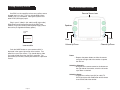
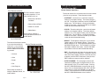
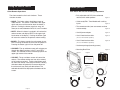
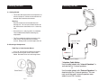
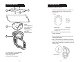
38114 Rosen_cover.p65
1
8/3/01, 10:26 AM
Table of Contents
7 Specifications
•
Power Supply: DC12V +/- 5%
•
Power Supply Consumption: 100VAC-240VAC@ 1 Amp
•
Input: TV/CATV NTSC system, F type connector,
Composite NTSC Video/Stereo Audio.
•
Output: 6.8” TFT Monitor
•
Stereo speaker output 0.5W(max)
Distortion <10%@1KHZ (Volume maximum)
3. Installation of your EM1
•
Operating temperature: 0°C~ +40°C
4. Using the Remote Control
•
Storage temperature: -40°C~ +85°C
•
Height: 9.25 in. (23.5 cm)
•
Base Diameter: 6 in. (15.24 cm)
•
Screen Case Width: 9 in. (22.9 cm)
•
Screen Diagonal: 6.8 in. ( 17.27 cm)
•
Screen Height: 4.1 in. (10.48 cm)
•
Weight: 3.54 lbs.
• Tuner Module width: 17.7
• Tuner Module Height: 2.7
• Tuner Module Depth: 12.7
Page 14
Section
1. Quick Reference Guide
2. About your EM1 System
Page
1-2
3
4-9
10-11
5. Using Auxiliary Audio/Video Sources
12
6. Trouble Shooting Your EM1
13
7. Specifications
14
6 Trouble Shooting Your EM1
3 Installing Your EM1
This section will give a brief trouble shooting guide
Please call Rosen Technical Support at 888-883-2790 for
further information or technical support.
• NO AUDIO -
Check volume level.
Check MUTE button.
Check volume level on AUX. input.
Check that correct interface cable is
used
• NO VIDEO -
Check desired source is selected by
pressing the MODE button.
Check Brightness, Color and Contrast
settings.
Check AUX input
Check Cable in for proper format
(STD,IRC, or HRC)
• NO POWER -
Check that power supply is plugged in.
Press the power button on the remote or
monitor.
• NO REMOTE - Check batteries
Page 13
5 Using Auxiliary Sources
1 EM1 Quick Reference Guide
3 Installing Your EM1
Remote Sensor Lens
Your EM1 has the capability to have one auxiliary source
plugged into it at a time. This may include DVD players,
closed circuit TV, camcorders, video game systems and
other NTSC (RCA type) inputs.
Plug in your V (video) L (left audio) and R (right audio)
RCA cables into the appropriate spot on the EM1 Tuner
module. Plug in your auxiliary source power supply (unless
the auxiliary is supplied with battery power).
Speakers
Auxiliary
Input
Power
Mode
tuner module
Push the MODE button on your remote until AV is
displayed in the upper right corner of the monitor. Turn
power on to your input source. This should display video
and audio should come from the EM1’s speakers. For
operation of your auxiliary source please refer to it’s operation
manual.
Channel Up/Down
Volume Up/Down
Power
• Depress the power button on either the remote
control or the right side of the monitor to power
the EM1 on.
Switching Channels
• Using either the remote control or the buttons on
the right side of the monitor, switch the channels
up or down as desired.
Switching Inputs
• To select the auxiliary input (AV) or cable (TV,
CATV) input press the mode button on the remote
or on the left side of the monitor.
Page 12
Page 1
1 EM1 Quick Reference Guide
4 Using the Remote Control
3 Installing Your EM1
Master Remote Operations
User Remote controller
The User remote is used for
day to day operation. It has
basic functions such as:
• Volume Up and Down
and Mute
• Channel Up and Down
• Power On and Off
• Mode Select
Please refer to Section 4,
Using the Remote Control, for
further details.
The intent of the Master remote
Master Remote controller
is to set up the monitor for
client use. It has all of the
features of the client remote
with the addition of the following controls:
• Contrast
• Color
• Bright
• Edit
• Auto Program
Please refer to, Section 4
Using the Remote Control, for
further details.
Page 2
The master remote has all the features of the user remote
plus five set up features. These features include:
• CONTRAST - Contrast has a scale from 0 (lowest
setting) to 16 (highest setting). The factory default is
set at 8. To change the contrast push the CONTRAST
button once. This will display a scale on the bottom
middle of the screen. Use the VOLUME up and down
arrows to select the desired setting.
• COLOR - The color setting has a scale from 0 (lowest
setting) to 16 (highest setting). The factory default
setting is at 8. To change the color, push the COLOR
button once. This will display a scale on the bottom
middle of the screen. Use the VOLUME up and down
arrows to select the desired setting.
• BRIGHT - The brightness setting has a scale from 0
(lowest setting) to 16 (highest setting). The factory
default setting is at 8. To change the brightness push
the BRIGHT button once. This will display a scale on
the bottom middle of the screen. Use the VOLUME
up and down arrows to select the desired setting.
• EDIT - The edit button will allow you to customize your
TV and CATV channel selections. To delete a channel
from one of these modes, select the channel you wish
to delete, push the EDIT button once, then push the
EDIT button once more to confirm selection.
• AUTO PROGRAM - The auto program feature will
automatically detect signal and select them as viewable channels in the TV and CATV mode. Pushing
the AUTO PROGRAM button once will bring up the
menu. You can choose between STD, IRC, and HRC
cable format by using the CHANNEL up and down
arrows. Once the format has been established, push
the AUTO PROGRAM button once to confirm.
Page 11
43 Using
the Your
Remote
Installing
EM1Control
2 About your EM1
3 Installing Your EM1
Your Rosen EM1 has the following components:
Client Remote Operations
The client remote has five basic functions. These
functions include:
• Fully adjustable 6.8” LCD, Infrared remote
receiver, with audio speakers.
Figure 1
• MODE - This button selects the different types of
video sources. The source is indicated in the upper
right-hand corner of the monitor when the button is
pushed. Pushing the button more than once, will
allow you to switch between CATV, AV, and TV modes.
• Cable ready EM-1 Tuner Module with auxiliary
Figure 2
inputs.
• MUTE - When this button is pushed it will reduce the
volume to zero and display MUTE in the upper right
hand corner of the display. Pushing the button again
will return the volume to the previous volume setting.
• One AC power adapter.
Figure 4
• One 15 foot interface cable.
Figure 5
• POWER - This button controls the main power of your
EM1. Pressing the button once will turn the power on.
Pressing the button again will turn the power off.
• One 15 foot interface cable.
• CHANNEL- The up and down arrows will navigate you
through the different stations in the TV and CATV
modes. The selected channels will be displayed in the
upper right corner of the monitor.
• Mounting Base Plate
• Two remote controls (one user remote and one
Figure 3
master remote)
(For use with internal speakers)
•
Hardware package (mounting screws)
Figure1
• VOLUME - The up and down arrows will control the
volume. The volume settings are from 0 (no volume)
to 16 (maximum volume). Pushing the buttons once
will move the volume in one step increments. Holding
the buttons down will gradually increase or decrease
the volume until you reach your desired level. The
selected volume will be displayed at the bottom of the
screen.
Figure 2
Figure 7
Figure 3
Figure 4
Figure 7
Figure 6
Figure 5
Page 10
Figure 6
(For use with External speakers)
Page 3
3 Installing Your EM1
3 Installing Your EM1
EM-1 FPD
A. Getting Started
• Locate the desired placement of components to
ensure a proper fit. Make sure the monitor has
enough room for desired movement.
Warning:
Excessive moisture and condensation will
damage unit. Be sure your chosen location for
the interface box and monitor are in a clean dry
area.
• Ensure there is a wall plug within 4’ of desired
Tuner module location before mounting any
components.
*15 ft. Interface Cable
• The Tuner module should be mounted on a flat
solid surface. Do not mount on an uneven
surface. Doing so will cause damage to the unit.
Coaxial input Cable
B. Mounting of Components
IR OUT MONITOR
L
R
VIDEO
AV1
EM-1 Tuner Module 9306-0131-000
• Use a 1/8” standard flat screw driver to remove
the base cover using the access notch shown
below. Be careful not to scar or damage cover.
EXTERNAL
ANT. IN
Table Top or Under Counter Mount
AC power Adapter
A
* Interface Cable Notice:
Use the cable labeled with “Internal Speakers” to
activate the Em-1 internal speakers
or
Use the cable labeled with “External Speakers” to
deactivate the Em-1 internal speakers. This scenario would be used if external speakers were
added to your EM-1 system.
Page 4
Page 9
3 Installing Your EM1
3 Installing Your EM1
B. Mounting of Components (Cont.)
• Plug pigtail from monitor into interface cable in
J-Box.
Table Top or Under Counter Mount
• Coil excess (service loop) wire in J-box and mount
monitor using supplied screws.
• Use the Mounting base plate as a template to mark
mounting holes
• Replace base cover.
• Mount base plate to monitor using 6-32 screws
provided
• Test for stability and desired range of motion.
Installing Tuner module
• Place Tuner module in desired location
( Dry Flat Place)
Note :
Mounting plate is only used when
you want to surface mount your
EM1 interface cable
• Select Appropriate cable
• Route 15ft interface cable from j-box to desired
Tuner module location.
• Plug pigtail from monitor into interface cable in
J-Box.
• Coil excess (service loop) wire in J-box and mount
monitor using supplied screws.
• Replace base cover.
• Test for stability and desired range of motion.
• Plug in Interface cable to proper location.
• Screw in cable to proper connector.
• Plug in power adapter to wall plug.
• Plug in power adapter into Tuner module.
Page 8
Page 5
3 Installing Your EM1
3 Installing Your EM1
C. Mounting on Wall to J-Box
2
1
• The EM1 is designed to mount in a round 3 1/2”
electrical junction box (J-Box) like the one
shown below.
J-Box
Note :
Mounting plate is
only used when
you want to
surface mount
your EM1
Interface cable
3
4
Note:
A J-box may be purchased at any local
hardware store
•
Make sure J-Box is secure before mounting
monitor assembly.
• Route 15ft interface cable from j-box to desired
Tuner module location.
• Use a 1/8” standard flat screw driver to remove
the base cover using the access notch as shown
below. When removing, be careful not to scar or
damage cover.
1.4 screws 10-32 x 1 Fhp 100 degree
2. # 10 washer ss 100 degree
3. Mounting baseplate
4. EM1 Main FPD Assembly
Page 6
Page 7