1
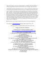
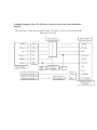
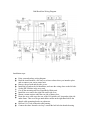
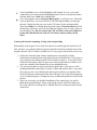
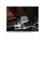
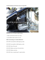
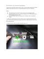
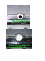
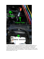
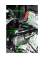
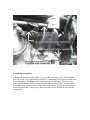
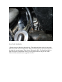
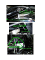
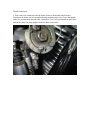
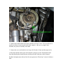
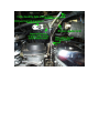
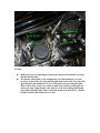
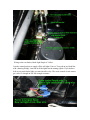
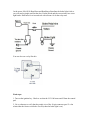
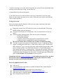
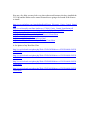
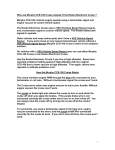
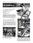
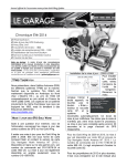
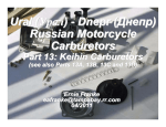
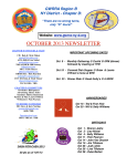
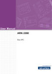
CCS-100 Cruise Control Installation: 2000 Road Star
December 2, 2010
By Scott Anderson
Introduction
The following is a summary of the information required to install a CCS-100 cruise
control system on a 2000 Yamaha Road Star. This information is provided for reference
only, and is not intended to replace the CCS-100 Installation Manual. If installing this
system on another model year Road Star, consult the appropriate Yamaha Road Star
service manual and verify all electrical connections.
This document is not intended to be a training course on how to install automotive
cruise controls on motorcycles. It is intended to be a supplement to the CCS-100
Installation Manual, for those persons that choose to install the CCS-100 cruise
control system on their motorcycle. Persons using this document, or any part thereof,
must accept full responsibility for their own actions in regard to the installation, and
subsequent operation of the motorcycle with the installed cruise control system.
In providing this information, I am assuming the reader is technically competent to do an
installation such as this, and has a basic understanding of the Yamaha Road Star; such as
removing the fuel tank, 12V wiring, etc. It will be necessary for the installer to fabricate
(or purchase from Murphs') a bracket for the keypad, mount the servo unit, mount the
vacuum canister, make electrical connections, as well as throttle and vacuum
connections.
I suggest you read this entire document, and become thoroughly familiar with the manual
before you proceed. Once you know what you need to do, the CCS-100 is not that
difficult to install. Everything that follows is based on the installation I did on my 2000
Road Star. I spent a lot of time just looking at different ways to mount the components,
and the instructions below should work just fine for the majority of installations.
You are welcome to use any or all of my ideas as you see fit. This is the way I did it on
my 2000 Road Star, and it works well. There are, no doubt, other ways to do the
installation and still end up with a safe and functional cruise control installation.
About the Author: I have worked as a Researcher & Designer of specialized conveyor
systems. I have fabricated specialized conveyor systems from 8 pound to 40 ton
machines. I spent 21 years working in blue print reading CAD designs of systems from
ground up to the fabrication, welding, electrical wiring, fluid hydraulics, pneumatics,
computer software to run the machines, to shipping and installing systems. I did own my
own company working on automotive repair for 8 years. I also work on small engines
from 2 stroke engine to 4 stroke gas engines. Weed eaters, lawn mowers, boat engines,
and 4 stroke engines. I repair and or build computers, cell phones and home appliances. I
also have done industrial electrical and electronics work. Currently I am semi retired.
I started riding motocross bikes at the age of 14. I do all my repairs to my motorcycles as
well as fellow rider’s machines for the past 38 years. I bought my first street bike at the
age of 19 and have been riding since then and still do my own repairs as well as fellow
rider’s machines. I am a life member of the Kentucky Riders Association and Kentucky
Biker Association. I hold an Amateur Radio Extra Class radio license. I have done local
disaster and emergency work since 1981. I am an Amateur Radio weather spotter and
have training by the Red Cross and the Kentucky NOAA weather center. I have designed
and built two houses. I have raised two boys. Both are in the military serving our country.
I have owned Yamaha, Honda, Kawasaki, and Suzuki motorcycles, from 185cc to larger
bikes, like Goldwings and Road Stars. I like repairing and detailing motorcycles just
about as much as riding them.
Be safe and use your God-given common sense. Please feel free to ask questions.
Scott Anderson, [email protected] Road Star Riders forums Andy_1602
Good Luck with your installation, and keep the rubber on the road.
Things you will need for installation
1. Road Star service manual (download off website)
http://www.paulmilner.com/yamaha/handbuch/handbuch.htm
2. Metric wrench set from 8mm to 18mm
3. Soldiering iron and solder for circuit boards and electrical wiring.
4. Screwdriver set
5. 3/8 Hand drill with drill bits
6. Metric tap and die set preferred can be SAE
7. Wire cutters and crimper
8. 1 piece of 1 ½ PVC pipe 7” long with end caps and pipe thread (Lowes)
9. PVC cleaner and glue ( Ace or Lowes)
10. 2 pcs 3/16 hose to 3/8 NPT adapter’s (Ace Hardware)
11. 3/8 NPT tap. Tap is in most tap and die sets
12. Two way check valve P/N 47150 in Help section of auto parts
13. Long wire ties 8” to 12” (small ones are in kit)
14. Metric hex bits, 4mm and 5 mm(Allen Head bits)
15. Sawzall or a Hack saw
16. A bench mounted vice for bending keypad bracket
17. Double sided mirror tape
18. 1 piece of 1 ¾ x 2” or 2x2” x1/4 thick plastic tile facial?
19. Digital volt ohms meter. Do not use any other volt ohm meters than digital it
can short the ECU
20. Electrical tape
Schematic diagram of the CCS-100 cruise control system, based on the installation
manual:
This is the basic wiring diagram of the system. The VSS wire but it is not needed and the
dipswitch is set to off.
2000 Road Star Wiring Diagram.
Installation steps:
Print, scan and enlarge wiring diagram.
Read the install manual a few times so to know about where you intend to place
and or connect your cruise control unit.
Remove the gas tank and the side covers.
Install the keypad on the left handlebar, and route the wiring down to the left side.
Set the DIP switches in the servo unit.
Cut off the mounting tab Turn Signal Relay/Relay unit.
Install the servo unit to the right side under side cover.
Mount vacuum canister under the rear side of battery box.
Route the servo cable up to the rear of the LH ignition coil, loop under right side
under frame. Then over the gas tank rubber mount on the right hand side to the
throttle cable mounting bracket at carburetor.
Drill an 11/64” hole in throttle cable housing.
Connect the short “throttle wire loop” around the bolt hole the throttle housing.
Connect the short “throttle wire loop” to the servo cable, using the beaded chain. I
used 5 links.
Connect the cable mounting bracket to the pull side of cables. NOTE: Road Stars
use a push pull setup for dual cable routing.
Make wiring connections, per the installation manual.
Make vacuum connections.
Power up the system, make sure it turns on/off from the Control pad and that both
brake levers actions read 12V on a volt ohms meter at the Purple wire. Brake
(Yellow) wire is found under riders seat
Reinstall the fuel tank and left side panel.
Test ride.
Electrical Connections, based on the installation manual:
Power connections, (12V): keypad Red wire connects, through the 4-pin
connector, to the servo unit Red wire. Red wire is connected to 12V power at the
battery. Other red wire is hook to tail light in the same location as the brake light
(Blue wire). This is 12V power that is switched by the ignition key. The manual
has you connect to the 12V side of the brake switch. The Purple wire is on the
Yellow wire connector on the rear fender. Select your power connection based on
the existing electrical loads you have. The CCS-100 is a low-power device, but
you might want to avoid using circuits already loaded down with extra lighting, or
other accessories. Note: I have a mod wrote up on the Road Star Clinic website
how to turn off all the lights when starter in is engaged. It helps some do to
cranking these big V twins.
Ground connections: Control pad Black wire and servo unit Black wire are
connected to chassis ground.
Control pad Brown (on/off), Yellow (resume), and Green (set) wires connect,
through the 4-pin connector, directly to the servo unit.
Servo unit Purple wire connects to the brake lights. The most convenient place to
make this connection is at the rear fender connection to tail/brake light. This
makes sure 12 volt is applied when either the front or rear brake is applied. This is
an important safety feature, so use a Voltmeter to verify before you make this
connection and it has 12V with key on Yellow wire.
Servo unit Blue wire is connected to the negative terminal of the Left side coil
Orange wire ignition coil. Check with switch on. There will be 12 volts on the
Red/Black wire terminal and about 8.3 volts on the Orange side of terminal. The
“noise suppressor” (supplied with CCS-100 kit) is a 20K Ohm (1 Watt) resistor.
You need to leave this in the circuit, so coil up the excess wire and tape it tight
use a wire tie to hold in place. I put mine right in front of the battery box. There is
some space there for extra wiring to be stored.
Control pad Gray wire is for backlighting of the keypad. In a car, you would
connect this wire to the instrument lighting dimmer circuit. I just spliced it inline
with the inline fuse at Red wire at handle bars.
Servo unit magnetic sensor Gray and Black (pair). Cut off extra wire. The black
is just a shield wire. So cut it off about 8” back leaving the Gray wire and tape
the ends. I hooked up the gray wire to the VSS sensor @ the ignition module.
That is the White wire coming from the speed sensor. It is not needed and if left
hooked up it will not let your self canceling turn signals work. So I put a splice in
it at the battery box. Do not connect wire. My test rides work great without it.
I removed it but did not cut it all off. Never know when you may switch
bikes.
Control pad: bracket, mounting, wiring, and waterproofing
Disassembly of the keypad: Use a small screwdriver to carefully pop the front bezel off.
This will leave you with the rubber keypad, the printed circuit board, and the back of the
keypad enclosure. The PC board is marked, so it is easy to get it put back the correct way.
1. I fabricated a bracket from chrome metal bracket, and used the existing
clutch/mirror mount bolt that crimps the bracket to the handle bars. I was going to
use a stainless steel kitchen spatula. Wife would never miss it. If you don’t want
to fabricate the bracket, there are now some ready-made brackets available, such
as the one available from Murphs Kits (www.murphskits.com).
2. You can use the adhesive tape to stick the keypad in place. I put a piece of tile
molding behind the control pad. It is about ¼ thick and needs to have a cut out for
the wiring to clear. I used double side mirror tape to hold it to my bracket. Then
used clear silicone sealant on the back side of keypad. Leave the self sticking tape
cover on while doing this. Cleanup the excess sealant then peel back at stick to the
bracket.
3. Once you are ready to do the final installation of the control pad, you need to
think about waterproofing it. These control pads weren’t made for outdoor use,
but can be effectively waterproofed. Murphs Kits sell a waterproof jacket for the
control pad.
A look from the bottom of the home made bracket and where I bolted it to.
Front view of switch. The key pad lights are bright so I may put a small ¼ watt resistor
inline to deal with the issue.
5. Install the control pad/bracket assembly, and route the control pad wires along the left
side down the frame. I have a Batwing Fairing on my Road Star so I already have the
convoluted tubing running down the frame already.
Cut the mounting tab off for the relay’s on right side.
Mount the Servo Unit and vacuum canister
1. Remove the bracket from the servo unit
2. Set the DIP switches in the servo unit:
DIP Switch settings for Yamaha Road Stars
SW1 OFF Sets controller for 4000 pulses per mile
SW2 OFF Sets controller for 4000 pulses per mile
SW3 OFF Selects Tach mode
SW4 OFF Medium sensitivity (See notes below)
SW5 OFF Medium sensitivity
SW6 OFF Selects “normally open” control switches
SW7 ON Selects “coil” as the source of timing pulses
Jumper (next to the DIP switches) must be “open” to select manual transmission. Pull the
jumper off the header pins, turn it 1/4 turn and reinstall it on just one of the pins.
Notes:
The manual says to remove the 10-pin connector when changing the DIP
switches, but doesn’t say why, so just do it with power off. This should be done
before hooking up the Servo unit.
Low and Medium sensitivity work quite well. (Medium is the recommended
setting)
3. Battery box should already removed. The servo unit is a tight fit under the left side
cover. So be sure the cables come out going up the frame with as little bend in the cable.
Do not kink the cable.
4. Mount the relays in there new place behind the battery box
4. Mount the vacuum canister sot that the vacuum line is facing toward you.
5. Mount the servo unit as seen in the left hand side. Re install the right hand side cover.
Use cable ties and metal strapping to hold servo. It is a tight fit and it is hard to move
without cable ties. The engine bolt needs to be shaved down about ½ inch then put
countersink bolt in hole with the metal strapping. The picture shows to use rubber. I used
double sided emblem tape so servo would not move. I used a die grinder to recess the bolt
head down about 3/8 to ½ inch.
Vacuum line connections
1. Run the vacuum hose to the intake. If you still have the factory AIS system installed
move the check valve to the intake to make the T connections. If not just cap off one end
like in my picture. The larger end of check valve goes to the intake. There are a few
riders out there that do not use a canister but the speed is not so stable. And for $10.00 it
is worth the piece of mined. My test rides held my Road Star right on the exacted speed
down hill and up hills. I don’t put my bike in a strain so large inclines at slow speeds I
change gears.
Servo Cable Installation:
1. Route the servo cable along the right side. Then under the frame to the left side right
before the middle motor mount bracket. Bring it back though to the left side looping over
the right side gas tank mount. Then down to the throttle cables. The Roads Stars have a
push pull system for the throttle cables. We are going to hook to the pull side of the
cables with the attached bracket supplied in the kit.
Throttle connection
1. First remove the carburetor from the intake. Remove choke knob and fuel lines.
Disconnect the heater unit wires and the throttle position sensor wires. Leave the throttle
cables on, just loosening the pull cable. I drilled an 11/64” hole just behind the pull cable
link for the short wire loop supplied in the kit. Bolt is also in kit.
2. Connect the beaded chain to the short “throttle wire loop”. Note: Use a scratch awl or
small screwdriver to open up the bead chain couplers – they are very tight. Once
installed, use pliers to carefully close them.
3. Connect the servo end with the wire loop with 5 beads of chain and the snaps in kit.
4. Reconnect throttle cable to the stock bracket on the top of carb. The throttle barrel
from the throttle plate should line up with the pull cable with just a little clearance.
Put blue locktight on nut side on bolt for extra protection. These big V twins do vibrate a
little.
NOTES:
Make sure there is no binding or interference between the throttle wire loop
and the throttle cable.
The throttle cable guide is only designed for one cable thickness, so it was
necessary to move the wire loop past the pull cable barrel end. Test with wide
open throttle from handlebars to see if cable follows in line with pull cable.
There will be slack in the servo cable so make sure it follows cable guide on
carb every time. Snap throttle a few times to see if it is working smooth and
stays inline with pull cable. That is what the stand off bracket is for. I had no
trouble without it but wanted it to be safe.
Wiring to the rear fender, Brake light Purple to Yellow.
I ran the control pad power supply off the tail lights. I have a Tour-pak on my Road Star
with a batwing fairing. I run leds in all the lights but the turning signals. If you do have
leds as your stock brake lights you must install a relay. The cruise control circuit can not
get a true 12v though an led. Not enough resistance.
In the newer 2004-2010 Road Stars and Roadliners/Straoliner the brake light is led so
you will need a simple mod for that also. Put the Diode and the two resistors in a water
tight bottle. Drill holes for wires and seal with silicone. Or do the relay mod.
You can also use a relay like this.
Final steps:
1. Turn on the ignition key. Check to see that the CCS-100 turns on/off from the control
pad.
2. Use a voltmeter to verify that the purple wire of the 10-pin connector gets 12 volts
when either the front or rear brake is used (when the brake light is on).
3. Be sure all wiring, servo cable, and vacuum lines are secured. Be sure the beaded chain
and loop do not rub on any wiring, vacuum lines, etc.
4. Reinstall the fuel tank and side panels
5. Use cable ties on servo cable and loose wires every where there is any loose play.
Make sure not to make fast turns in servo cable. If the cable stays in place the better the
cruise control response is.
Testing the system:
Find a convenient stretch of highway. When you are at speed, and away from other
vehicles, turn the system on.
Engage the system: Press SET and slowly relax your throttle hand. The system
should regulate your selected speed
Check the COAST and ACCEL functions. The CCS should lock in at the new
speed.
Check for proper disengagement: There are four ways to disengage:
o 1. Front brake actuation
o 2. Rear brake actuation
o 3. Turn the system off (keypad switch or optional power switch)
o 4. Sudden increase in engine RPM (clutch disengagement)
My test ride results: Drove 53 miles total. 16 miles was Interstate riding.
Test rides 5th gear cruise works at 43 mph and up. 4th gear 33 mph and up. When
engine is running about 2000 rpm’s is when cruise starts to work. I like the idea
that it works in 4th gear. I do some slow rides with local biker groups and we ride
at 45 to 50 mph at times. The 2000 Road Stars have a 33 tooth front sprocket.
2004 models and up have 32 tooth sprocket. That makes the gearing a little tall at
that speed for the 1999 thru 2003 Road Stars. Both brake levers disengages cruise.
A pull of the clutch disengages the cruise with a 1 second rpm surge of about 500
rpm’s. Coast, Resume, and Accelerate all worked perfect.
I bought my kit from [email protected] they had the best price. They also have
kits in stock with extra parts and replacement Control pads if need. The install
manuals can also be down loaded from there website.
Parts not supplied with CCS-100:
Cable ties, 8”
Control pad bracket, shop made or available at Murphs' Kits. Email Murph at
[email protected]
A few bolts and nuts that most people have in there house.
Water proof jacket for keypad sold by [email protected]
Other items may be required, depending on your particular installation
Don’t forget the relay for the leds
Here are a few links you may look over where other model motorcycles have installed the
CCS-100 and the Rostra cruise control. Rostra kits are going to be around $100.00 more
to install.
http://www.paulmilner.com/yamaha/handbuch/Rostra_Electronic_Cruise_Control_Stratol
.pdf
http://www.linerwiki.com/liner/Audiovox_CCS100_Cruise_Control_Installation.pdf
http://www.murphskits.com/catalog/product_info.php?products_id=422
http://gadgetjq.com/electronic_cruise.htm
http://www.murphskits.com/catalog/docs/Rostra%20install.htm
http://home.comcast.net/~bp/cc/
http://www.fjr1300.info/howto/audiovox.html
http://www.valkyrieriders.com/shoptalk/CruiseControl.htm
A few photos of my Road Star Ultra
http://www.facebook.com/photo.php?fbid=470926205880&set=a.470925940880.248329
.662820880
http://www.facebook.com/photo.php?fbid=470926290880&set=a.470925940880.248329
.662820880
http://www.facebook.com/photo.php?fbid=470930820880&set=a.470925940880.248329
.662820880
http://www.facebook.com/photo.php?fbid=470931010880&set=a.470925940880.248329
.662820880