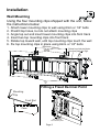
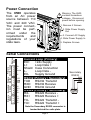
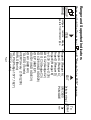
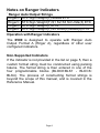
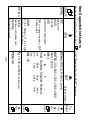
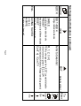
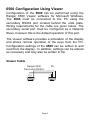
1
Quick Start Manual
For use with software versions 1.5+
6500-601 Rev 1.1
Introduction
The 6500 is a member of the latest generation of Ranger
remote displays.
Features
Six digit electromechanical alpha-numeric display
Annunciators for Net/Motion/Center of Zero
Two independent serial ports supporting RS232,
RS422 and 20mA Current Loop (active and passive)
Auto baud / auto select data source
User programmable serial data formats
Support for Ranger Networking/Summing and Modbus
ASCII
Manuals
The Quick-Start Manual (this document) is intended for
use by installers familiar with the Ranger 6500. The
other manuals covering the 6500 are:
6500 Reference Manual (6500-600);
6500 Operators Manual (6500-602);
6500 Mounting Options Manual (6500-603).
These manuals are available for download from the
Ranger Instruments web site:
www.rangerinstruments.com.
Warning
!
The 6500 contains high voltages. Disconnect the AC
power supply before opening the unit.
DISCONNECT POWER
BEFORE OPENING
Page 1
Installation
Wall Mounting
Using the four mounting clips shipped with the unit, follow
the instructions below:
1.
2.
3.
4.
5.
6.
Attach lower mounting clips to wall using 6mm or 1/4" bolts
Predrill top holes, but do not attach mounting clips
Angle top out and insert lower mounting clips into front track
Insert two top mounting clips into front track
Rotate top toward wall, until top mounting clips touch the wall
Fix top mounting clips in place using 6mm or 1/4" bolts
(Minimum 250mm)
2 6
4
Setup keys behind plate.
Reverse plate for Kg/t.
4
5
167mm
3
3
3
1
Fitting a Fixed Decimal Point
Mounting
Clip
Front Slot
Case
Affix Decimal
Point as Required
Page 2
Power Connection
The 6500 operates
from an AC power
source between 110
VAC and 240 VAC.
The power connection must be performed under the
requirements
and
regulations of your
state laws.
!
Warning: The 6500
contains hazardous
voltages. Disconnect
power before opening.
1. Remove 2 Screws
2. Slide Power Supply
Out
3. Connect AC Supply
4. Slide Power Supply In
5. Replace Screws
Primary
Secondary Primary
Loop
Current
RS232
RS422
EX+
L+
Shield
LEX-
Primary
RS422
Display
PCB
Serial Connections
RXRX+
TXTX+
TXD
GND
RXRX+
TXTX+
Current Loop (Primary)
EX+
+24v Supply
L+
Loop Data +
Shield Case Connection
LLoop Data EXSupply Ground
RS232 (Primary / Secondary)
TXD
RS232 Transmit
RXD
RS232 Receive
GND RS232 Ground
RS422 (Primary / Secondary)
RXRS422 Receive RX+
RS422 Receive +
TXRS422 Transmit TX+
RS422 Transmit +
Note the Secondary RS232 connector is
located behind the units plate.
Page 3
Secondary
RS232
RXD
TXD
GND
2 3 5
Remote Display Serial Wiring Diagrams
RS232
Ranger 6500
Primary RS232
TXD
RXD
GND
Ranger
5000/5100
or PC
2 3 5
RS422/RS485
Ranger 6500
Primary RS422
Ranger
5000/5100
RX- 6
RX+ 7
TX- 8
TX+ 9
RXRX+
TXTX+
20mA Current Loop
Connections
to a Passive
Loop Transmitter
+
-
EX+
L+
SH
LEX-
6500 Loop
Connector
Page 4
Ranger Loop
Transmitter
(RI 0214)
Ranger and Supported Indicators
ITEM
EDIT
Default setting: [ ]
Press and hold the Group key ( GROUP ) until "Remote Setup 6500" appears.
GROUP
BRAnD
Configure remote display
operate from indicator type.
to RngerA (Ranger A)*
UMC600
RngerC (Ranger C)*
PCMODE
RngerD (Ranger D)*
RngerE (Ranger E)*
AvL130 (Avery L130)
GDG C2 (Gedge C2)
GDG C3 (Gedge C3)
AD 4328 (A&D AD4328)
AD EP (A&D EP)
AD4531 (A&D AD4531)
AD HV (A&D HV)
TOLEDO (Toledo)
AVERY (Avery L105/L200)
BARLO (Barlo)
PHLPS (Phillips 1577, 1627)
LODEC (Lodec)
Page 5
To
Enter
ITEM
Notes on Ranger Indicators
*
Ranger Auto Output Strings
RngerA STX Sign Weight(7) Status ETX
RngerC STX Sign Weight(7) S1 S2 S3 S4 Units(3) ETX
RngerD STX Sign Weight(7) ETX
RngerE STX Sign Weight(7) S5 Units(3) Mode(4) ETX
Operation with Ranger Indicators
The 6500 is designed to operate with Ranger Auto
Output Format A (Rnger A), regardless of other user
configured indicators.
Non-Supported Indicators
If the indicator is not provided in the list on page 5, then a
custom format string must be constructed using parsing
tokens. The format string is then entered in one of the
four programmable blocks (BLOCK:BLK1 - BLOCK:
BLK4). The process of constructing format strings is
beyond the scope of this manual, and is covered in the
Reference Manual.
Page 6
Non-Supported Indicators
ITEM
Default setting: [ ]
[SCAn], RS232, RS422, Loop
EDIT
Press and hold the Group key ( GROUP ) until "Remote Setup 6500" appears.
GROUP
SERIAL SRC
Data source
BAUD
Baud rate
BITS
Serial format configuration
1stop
2stop
-none
Term
[AUTO], 300, 600, 1200, 2400, 4800,
9600, 19200
[n81-]
n
8
1
Parity Databits Stopbits Network
8bits
7bits
[YES], NO
[5], 10, 20, noTMO (no time out)
[00] - 99
Odd
Even
ITEM to change position, EDIT
none
to change digit.
ADDR
Set the address of the serial
port for use with PC Mode
OPTIOn TimE.O
Data time out to show error
ShoWDp
Show decimal point
Page 7
To
Enter
ITEM
ITEM
GROUP
GROUP
ITEM
GROUP
ITEM
BLK 1-BLK 4
Configurable data blocks
SAVING SAVED
Reset blocks to defaults
RESET
[R, 1, 2, 3, 4]
EDIT
[ConT n] / ConT Y
Default setting: [ ]
Enable/disable data blocks
ITEM to change position, EDIT to enable/disable
PRESET
Select format to preset: [1], 2,3,4
Preset brand to different blocks Select indicator (Refer to Ranger and Supported)
EnABLE
Refer to token list
Non-Supported Indicators (continued)
GROUP
BLOCK
-EndExit setup
NoSAVE
(If data not changed)
Page 8
To
Enter
Hold
GROUP
GROUP
ITEM
ITEM
ITEM
6500 Configuration Using Viewer
Configuration of the 6500 can be performed using the
Ranger 6500 Viewer software for Microsoft Windows.
The 6500 must be connected to the PC using the
secondary RS232 port located behind the units plate.
Wiring requirements for the cable are given below. The
secondary serial port must be configured as a Network
Slave, however this is the default operation of this port.
The Viewer software provides a simulation of the display
and allows remote operation of the keys from the PC.
Configuration settings of the 6500 can be written to and
read from the display. In addition, settings can be altered
as necessary and may also be written to file.
Viewer Cable
Ranger 6500
Secondary RS232
2 3 5
PC
2 3 5
Page 9
Other Operating Modes
The configuration of these modes is beyond the scope of
this manual. Please refer to the Reference Manual for a
full description. These modes are available from the
Serial Setup menu, accessed by holding the ITEM key, and
selecting the required mode.
Summing Network Master
The 6500 queries and sums the weight of a number of
slave 5000 / 5100 units connected together on a multidrop RS422/RS485 bus. The resulting total weight is
displayed on the 6500.
Ranger 1200 Remote Display
This mode converts the raw counts output from the
Ranger 1200 and display a weight reading.
Secondary Port Functions
These options are available from the General menu
(GENRL SETUP), accessed by holding the EDIT key.
Network Slave
This mode allows a PC/PLC to operate the display using
the Ranger Networking commands. The Windows Viewer
software requires this mode.
Modbus Slave
The 6500 can be configured to operate as a Modbus
ASCII slave, allowing a PLC to operate the display.
Page 10
(This page left intentionally blank)
Page 11
(This page left intentionally blank)
Page 12
(This page left intentionally blank)
Page 13
Error Messages
Configuration Errors
Error
Description
ER.DAT There is no data being received by the unit.
ER.RX The baud rate/parity or stop bits are incorrect.
ER.ETX No ETX character was found in the data stream.
ER.FLD The data stream does not match any format.
ER.LEN The field to be displayed is longer than 6 digits.
Weighing Errors
(U-----) The weight is below the minimum allowable
weight reading.
(O-----) The weight is above the maximum allowable
weight reading.
(------)
The weight being transmitted is invalid (as per
remote indicator).
Operating Errors
Code
Error Description
E 0001 The power supply voltage is too low
E 0002 The power supply voltage is too high
E 0100 The digital setup information has been lost
E 0300 All setup information has been lost
E 0400 The factory information has been lost
E 0800 The EEPROM memory chip has failed
E 8000 The EPROM memory chip has failed
The “E” type error messages are in hexadecimal and are
additive (eg 0900 = 0800 + 0100).
Page 14
N2708
This document contains a general guide only of the operation of the
product and shall not form any contract. The specifications of the
product may be altered without notice.
RANGER INSTRUMENTS
www.rangerinstruments.com
[email protected]