1
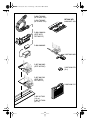
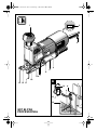
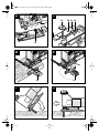
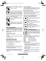
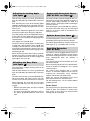
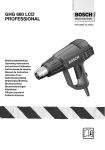
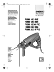
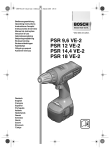
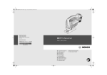
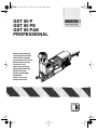
2 609 931 878.book Seite 1 Donnerstag, 4. November 2004 8:06 08
GST 85 P
GST 85 PE
GST 85 PAE
PROFESSIONAL
Bedienungsanleitung
Operating instructions
Instructions d’emploi
Instrucciones de servicio
Manual de instruções
Istruzioni d’uso
Gebruiksaanwijzing
Betjeningsvejledning
Bruksanvisning
Brukerveiledningen
Käyttöohje
Οδηγία χειρισµού
Kullan∂m k∂lavuzu
* Des idées en action.
2 609 931 878.book Seite 2 Donnerstag, 4. November 2004 8:06 08
2 • 2 609 931 878 • 04.11
2 609 931 878.book Seite 3 Donnerstag, 4. November 2004 8:06 08
2 600 793 009
(Ø 19 mm, 3 m)
1 610 793 002
(Ø 19 mm, 5 m)
MT 300 WP:
0 603 037 103
2 608 190 010
(GST 85 P/
GST 85 PE)
2 600 306 005
2 607 001 069
2 607 001 082
(GST 85 PAE)
2 607 010 079
(5 x)
2 607 001 201
(GST 85 P/
GST 85 PE)
2 605 438 212
2 602 317 031
(1,4 m)
2 602 317 030
(0,7 m)
3 • 2 609 931 878 • 04.11
2 609 931 878.book Seite 2 Donnerstag, 4. November 2004 8:06 08
2
1
3
4
5
6
7
9 8
4 • 2 609 931 878 • 04.11
30
45
GST 85 PAE
PROFESSIONAL
30
16
15
15
15
A
0
13 12 11
45
10
14
8
2 609 931 878.book Seite 3 Donnerstag, 4. November 2004 8:06 08
B
C
19
20 21 22
18
17
0
15
30
45
8
15
D
E
23
F
5 • 2 609 931 878 • 04.11
23
G
2 609 931 878.book Seite 1 Donnerstag, 4. November 2004 8:06 08
Tool Specifications
Jigsaw
GST 85 P
PROFESSIONAL
0 601 584 1..
[W]
[W]
[spm]
[mm]
580
350
3 100
26
–
●
●
GST 85 PE
PROFESSIONAL
0 601 584 6..
GST 85 PAE
PROFESSIONAL
0 601 584 8..
580
350
500 – 3 100
26
●
●
●
[mm]
[mm]
[mm]
[°]
85
20
10
0 – 45
85
20
10
0 – 45
[kg]
2.4
2.4
Article number
Jigsaw
Article number
Rated input power
Output power
Stroke rate at no load
Stroke
Stroke rate preselection
Orbital action
Sawdust Blower Device
Cutting capacity, max.
Wood
Aluminium
in non-alloy steel
Bevel cuts (left/right)
Weight according to EPTA-Procedure
01/2003
Protection class
/ II
/ II
Please observe the article number on the type plate of your machine. The trade names of the individual machines may vary.
The values given are valid for nominal voltages [U] of 230/240 V. For lower voltages and models for specific countries, these
values can vary.
Machine Elements
The numbering of the machine elements refers to
the illustration of the machine on the graphics
page.
While reading the operating instructions, unfold
the graphics page for the machine and leave it
open.
1 Rotatable top handle with pushbutton
2 Stroke rate preselection thumbwheel
(GST 85 PE/GST 85 PAE)
3 Allen key
4 On/Off switch
5 Vacuum connection (GST 85 PAE)
6 Switch for sawdust blowing device
7 Lever for adjustment of pendulum action
8 Base plate (GST 85 P/GST 85 PE)
8 Base plate with mit interior extraction
channel (GST 85 PAE)
9 Stroke rod
10 Guide roller
11 Saw blade*
12 Cover guard (GST 85 PAE)
13 Contact protector
12 • 2 609 931 878 • TMS • 27.10.04
14
15
16
17
18
19
20
Scale for mitre angle
Screw
Angle gauge**
Thread
Positioning pin/marking
Splinter guard
Screw for replaceable base-plate cover
(GST 85 PAE)
21 Replaceable base-plate cover
(GST 85 PAE)
22 Slider (GST 85 PAE)
23 Circle cutter/parallel guide*
* Not all of the accessories illustrated or described are
included as standard delivery.
**Commercially available (not included in the delivered
items)
Intended Use
The machine is intended for making separating
cuts and cut-outs in wood, plastic, metal, ceramic
plates and rubber while resting firmly on the
workpiece. It is suitable for straight and curved
cuts with mitre angles to 45°. The saw blade recommendations are to be observed.
English - 1
2 609 931 878.book Seite 2 Donnerstag, 4. November 2004 8:06 08
Noise/Vibration Information
Measured values determined according to
EN 60 745.
Typically the A-weighted sound pressure level of
the machine is 83 dB (A). Measurement uncertainty K=3 dB.
When working, the noise level can exceed
85 dB (A).
Wear hearing protection!
The typically weighted acceleration is 4 m/s2.
For Your Safety
Read all instructions. Failure to
follow all instructions listed below
may result in electric shock, fire
and/or serious injury.
Additionally, the general safety instructions either
in the enclosed booklet or those added in the
centre of these operating instructions must be observed.
SAVE THESE INSTRUCTIONS.
■ Secure the workpiece. A workpiece clamped
with clamping devices or in a vice is held more
securely than by hand.
■ Take protective measures when dust can
develop during working that is harmful to
one’s health, combustible or explosive. Example: Some dusts are regarded as carcinogenic. Work with dust/chip extraction and
wear a dust mask.
■ Keep your workplace clean. Material mixtures are particularly dangerous. Dust of light
metal can be inflammable or explode.
■ Do not work materials containing asbestos. Asbestos is considered carcinogenic.
■ Always wait until the machine has come to
a complete stop before placing it down. The
tool insert can jam and lead to loss of control
over the power tool.
■ Do not use a machine with a damaged
mains cable. Do not touch the damaged cable and pull the mains plug when the cable
is damaged while working. Damaged cables
increase the risk of an electric shock.
■ Connect machines that are used in the
open via a residual current device (RCD).
■ Keep your hands away from the sawing
range. Do not reach under the workpiece.
Contact with the saw blade can lead to injuries.
13 • 2 609 931 878 • TMS • 27.10.04
■ Guide the machine against the workpiece
only when it is switched on. Otherwise there
may be danger of kickback when the tool insert
jams in the workpiece.
■ Pay attention that the base plate 8 rest securely on the material while sawing. A
jammed saw blade can break or lead to kickback.
■ When the cut is completed, switch off the
machine and then pull the saw blade out of
the cut only after it has come to a standstill.
In this manner you can avoid kickback and can
place down the machine securely.
■ Use only sharp, flawless saw blades. Bent
or unsharp saw blades can break or cause
kickback.
■ Do not brake the saw blade to a stop by applying side pressure after switching off.
The saw blade can be damaged, break or lead
to kickback.
■ Use suitable detectors to determine if utility lines are hidden in the work area or call
the local utility company for assistance.
Contact with electric lines can lead to fire and
electric shock. Damaging a gas line can lead
to explosion. Penetrating a water line causes
property damage or may cause an electric
shock.
■ Hold the power tool only by the insulated
gripping surfaces when performing an operation where the cutting tool may contact
hidden wiring or its own power cord. Contact with a “live” wire will also make exposed
metal parts of the power tool “live” and shock
the operator.
Replacing/Inserting the Saw
Blade
■ Before any work on the machine itself, pull the
mains plug.
Inserting the Saw Blade
■ Wear protective gloves when assembling
the saw blade. Contact with the saw blade
can lead to injuries.
Before inserting the saw blade 11 set the adjusting lever for pendulum action 7 to level III.
Press down the orange pushbutton
in the rotatable top handle 1 until it
can be felt to engage.
English - 2
2 609 931 878.book Seite 3 Donnerstag, 4. November 2004 8:06 08
Turn the rotatable top handle 1 approx. three rotations in counterclockwise direction.
Insert the saw blade 11 in the
stroke rod crosswise to the cutting
direction. Turn the serrated edge of
the saw blade to the cutting direction. Slightly lift the saw blade so
that the back of the saw blade
comes to rest in the groove of the guide roller 10.
Allow it to notch by pulling slightly.
Turn the rotatable top handle 1 in
clockwise direction until a snap is
heard (click).
Contact Protector
The contact protector 13 attached to the housing
prevents unintentional contact with the saw blade
while working and should not be removed.
Sawdust Blower Device
The sawdust blower device leads an air jet to the
saw blade. The air jet keeps sawdust from covering the cutting line during operation.
The air flow can be switched on or off with the
switch for the sawdust blowing device 6:
Sawdust blowing level I:
Low airstream, for cuts in metals
and when coolants/lubricants are
used.
Sawdust blowing level II:
Medium airstream, for cuts in materials with low chip removal rate,
e. g. hardwood.
Afterwards, push up the orange
pushbutton at the rotatable top handle 1 again to the starting position.
Sawdust blowing level III:
High airstream, for cuts in materials
with high chip removal rate, e. g.
soft wood, plastic, etc.
Starting Operation
Observe correct mains voltage: The voltage of
the power source must agree with the voltage
specified on the nameplate of the machine.
Equipment marked with 230 V can also be connected to 220 V.
Pendulum Action Setting
The four pendulum action settings
allow optimum adaptation of cutting
speed, cutting capacity and cutting
pattern to the material being
sawed.
Switching On and Off
To start the machine, press the On/Off switch 4
forward.
To switch the machine off, press the On/Off
switch 4 to the rear.
Stroke Rate Preselection
(GST 85 PE/GST 85 PAE)
The required stroke rate can be preselected (also
during operation) using the thumbwheel 2.
1 – 2 = low stroke rate
3 – 4 = medium stroke rate
5 – 6 = high stroke rate
The required stroke rate is dependent on the material and the working conditions and can be determined by a practical trial.
After working for longer periods at low stroke rate
allow the machine to cool down by running it at
maximum stroke rate and no-load for approx.
3 minutes.
14 • 2 609 931 878 • TMS • 27.10.04
The pendulum action can be adjusted in four
steps with the adjustment lever 7. Switching is
possible with the machine running:
Step 0:
No pendulum action
Step I:
Small pendulum action
Step II:
Medium pendulum action
Step III:
Large pendulum action
Recommendations:
– The more narrow and clean the cutting edge
should be, the lower the pendulum action level
should be selected (or switched off).
– For thin materials, e. g. sheet metal, switch the
pendulum action off.
– For hard materials, e. g. steel, work with low
pendulum action.
– For soft materials and when sawing in the direction of the grain, work with maximum pendulum action.
The optimal setting can be determined by practical testing.
English - 3
2 609 931 878.book Seite 4 Donnerstag, 4. November 2004 8:06 08
Adjusting the Cutting Angle
(see figure A )
Replaceable Base-plate Covers
(GST 85 PAE – see figure C )
GST 85 PAE: Remove the cover guard 12 and
open the slider 22 at the bottom side of the base
plate.
After loosening the screw 15 and sliding lightly
forward in the direction of the saw blade, the base
plate 8 can be swung to the right or left to a maximum of 45°.
After coarse adjustment, tighten the screw 15 so
that the base plate 8 can still just be adjusted.
The cutting angle can be pre-adjusted by means
of the scale for mitre angles 14. Precise adjustment with use of a commercial angle gauge 16 is
recommended.
Then tighten the screw 15 again.
To achieve precise cutting angles, the base plate
is fitted with a locking device at 0° and 45° (left
and right). For this, however, the base plate must
be pushed back (towards the motor) to the stop,
so that the notch in the base plate engages in the
positioning pin 18.
When returning the base plate to the 0° (normal)
position, press the base plate lightly in the direction of the motor until it can be felt to engage and
again tighten the screw 15.
Offsetting the Base Plate
(see figure B )
For sawing close to edges, the base plate can be
offset to the rear:
GST 85 PAE: Remove the cover guard 12 and
open the slider 22 at the bottom side of the base
plate.
Use Allen key 3 to take out screw 15 completely.
Lift the base plate and move it to the rear such
that the screw can be turned into the rear thread.
When tightening the screw 15, the base plate
must be pressed to the rear until it can be felt to
engage.
– With the base plate offset, only the 0° (normal)
position can be used.
– The circle cutter/parallel guide 23 as well as
the splinter guard 19 cannot be used in this
case.
15 • 2 609 931 878 • TMS • 27.10.04
The base plate 8 is originally equipped with a replaceable base-plate cover 21 made of plastic. It
ensures good sliding capability on wood and
plastic surfaces, and largely avoids scratching of
sensitive surfaces.
After loosening the six screws 20, the replaceable plastic base-plate cover can be exchanged
against a steel insert, which is intended for use
on metal surfaces.
Splinter Guard (see figure
C
)
To avoid fraying of the surface, install the splinter
guard 19 by pressing it into the base plate 8.
The splinter guard cannot be used for certain saw
blade types (e. g., saw blades with set teeth).
Dust/Chip Extraction
(GST 85 PAE)
The machine can be plugged directly into the receptacle of a Bosch all-purpose vacuum cleaner
with remote starting control. The vacuum cleaner
starts automatically when the machine is
switched on.
The vacuum cleaner must be suitable for the material to be worked.
When vacuuming dry dust that is especially detrimental to health or carcinogenic, use a special
vacuum cleaner.
For external dust extraction with a vacuum
cleaner, an extraction adapter must be used as
required (see accessories). Insert extraction
adapter and vacuum connection firmly.
Attach the vacuum connection 5 to the base
plate 8 and connect the extraction hose.
For low blowing effect, set the sawdust blower
switch 6 upward.
Cover Guard
The transparent cover guard 12 enables the collection of chips and sawdust. To achieve optimum results, it must always be mounted when
working with dust extraction.
English - 4
2 609 931 878.book Seite 5 Donnerstag, 4. November 2004 8:06 08
Tips
Maintenance and Cleaning
For tight curves it is best to use a narrow saw
blade.
When sawing metal or similar materials, apply
coolant/lubricant alongside the cutting line.
Circle Cutter/Parallel Guide
(Accessory – see figures D –
E
)
With the combined circle cutter/parallel guide 23,
circular cutouts or parallel cuts in materials of up
to 30 mm thickness can be made.
Plunge Cutting (see figures
F
–
G
)
Plunge cuts may only be applied to soft materials, such as wood, aerated concrete, gypsum plaster boards, etc.!
Place the machine with the front edge of the base
plate on to the workpiece and switch on. Firmly
hold the machine against the workpiece and by
tilting the machine, slowly plunge the saw blade
into the workpiece.
When the base plate fully lays on the surface,
continue sawing along the cutting line.
Removing the Rotatable Top Handle
For easier sawing in particularly tight locations,
the rotatable top handle 1 can be removed. For
this, press the orange pushbutton beyond the
latching point and pull off the rotatable top handle
upward at the same time.
Before assembling the rotatable top handle 1,
push up the orange pushbutton back into the
starting position again. Attach the rotatable top
handle 1 and press downward until it can be felt
to engage.
■ Before any work on the machine itself, pull the
mains plug.
■ For safe and proper working, always keep the
machine and its ventilation slots clean.
■ In order to avoid operational malfunctions, do
not saw gypsum board from below or overhead.
In extreme working conditions, conductive dust can accumulate in the interior
of the machine when working with
metal. The protective insulation of the
machine can be degraded. The use of a
stationary extraction system is recommended in such cases as well as frequently blowing out the ventilation slots
and installing a residual current device (RCD).
The guide roller 10 should occasionally be
checked for wear and lubricated with a drop of oil.
If it is worn, it must be replaced.
If the machine should fail despite the care taken
in manufacturing and testing procedures, repair
should be carried out by an authorized after-sales
service centre for Bosch power tools.
In all correspondence and spare parts orders,
please always include the 10-digit article number
given on the nameplate of the machine.
WARNING! Important instructions for connecting a new 3-pin plug to the 2-wire cable.
The wires in the cable are coloured according to
the following code:
strain relief
live = brown
neutral = blue
To be fitted
by qualified
professional only
Do not connect the blue or brown wire to the
earth terminal of the plug.
Important: If for any reason the moulded plug is
removed from the cable of this machine, it must
be disposed of safely.
16 • 2 609 931 878 • TMS • 27.10.04
English - 5
2 609 931 878.book Seite 6 Donnerstag, 4. November 2004 8:06 08
Environmental Protection
Recycle raw materials instead of disposing as
waste
The machine, accessories and packaging should
be sorted for environmental-friendly recycling.
These instructions are printed on recycled paper
manufactured without chlorine.
The plastic components are labelled for categorised recycling.
Australia and New Zealand
Robert Bosch Australia Pty. Ltd.
RBAU/SPT
1555 Centre Road
P.O. Box 66
3168 Clayton/Victoria
✆ ............................................. +61 (0)1 / 3 00 30 70 44
Fax ............................................. +61 (0)1 / 3 00 30 70 45
www.bosch.com.au
Service and Customer
Assistance
Exploded views and information on spare
parts can be found under:
www.bosch-pt.com
Great Britain
Robert Bosch Ltd. (B.S.C.)
P.O. Box 98
Broadwater Park
North Orbital Road
Denham-Uxbridge
Middlesex UB 9 5HJ
✆ Service ............................ +44 (0) 18 95 / 83 87 82
✆ Advice line .................... +44 (0) 18 95 / 83 87 91
Fax ............................................. +44 (0) 18 95 / 83 87 89
Ireland
Beaver Distribution Ltd.
Greenhills Road
Tallaght-Dublin 24
✆ Service ................................... +353 (0)1 / 414 9400
Fax .................................................... +353 (0)1 / 459 8030
Declaration of Conformity
We declare under our sole responsibility that this
product is in conformity with the following standards or standardization documents: EN 60 745
according to the provisions of the directives
89/336/EEC, 98/37/EC.
Dr. Egbert Schneider
Senior Vice President
Engineering
Dr. Eckerhard Strötgen
Head of Product
Certification
Robert Bosch GmbH, Geschäftsbereich Elektrowerkzeuge
Subject to change without notice
17 • 2 609 931 878 • TMS • 27.10.04
English - 6
2 609 931 878.book Seite 1 Donnerstag, 4. November 2004 8:06 08
* Des idées en action.
Chlor
Robert Bosch GmbH
Geschäftsbereich Elektrowerkzeuge
70745 Leinfelden-Echterdingen
www.bosch-pt.com
2 609 931 878 (04.11) O / 81
Printed in PRC