1
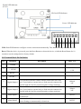
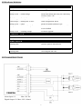
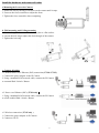
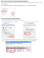
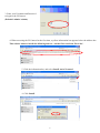
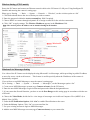
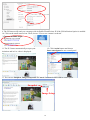
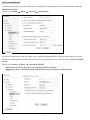
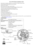
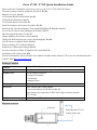
Zavio F7110 / F7115 Quick Installation Guide
Please follow the installation steps below to set up your F7110 / F7115 Box IP Camera.
Check the package contents against the list below. See P.1
Physical overview. See P.1
I/O Terminal Block Pin Definition. See P.2
LED Indicator Definition. See P.3
I/O Terminal Block Circuit. See P.3
Install the hardware and connect all cables. See P.4
Microsoft OS: Use the software CD to install Intelligent IP Installer. See P.5
Access the IP Camera using Intelligent IP Installer. See P.5
Mac OS using Safari Browser. See P.7
Change lighting environment setting. See P.8
Change the Web Interface into your preferred language. See P.8
Use IP Camera via Mobile Phone. See P.8
Wireless Setting (F7115 Model). See P.9
Windows Live Messenger Setting. See P.9
Access to Internet via Static IP, Dynamic IP or both. See P.11
Application of IP Camera. See P.13
For more information, please check the User Manual available in the Software CD or you can download the latest
software from http://www.zavio.com
Package Contents
Camera
F7110 / F7115 IP Camera
Quick Installation Guide
Brief product information and quick installation
Software CD
IP Surveillance Software
Intelligent IP Installer
User Manual
Language Packs
Mounting Bracket
Three screw, Lock ring, and one bracket
Accessory
BNC female to RCA male adapter
8 pin terminal block for DI/DO and RS-485
Dual antenna for connection of IEEE 802.11b/g/n wireless network
(F7115 only)
Adaptor
12V DC, max 12W
Physical overview
Auto Iris
Dual Antenna (F7115)
Analog Video Out
1
WLAN LED Indicator
(F7115)
SD Card LED Indicator
Power LED Indicator
8
7
6
5
4
3
2
1
WPS: Push WPS button to configure wireless connection automatically. This function is only available in F7115.
Reset: When the device is powered, press the Reset Button to reboot the device, or hold the Reset Button for 10
seconds to set the settings back to factory default.
I/O Terminal Block Pin Definition
PIN
Definition
Description
Max. V/A
1
Ground
-
2
+ 12V DC
12V DC
1.2W
3
RS-485 -
-
4
RS-485 +
-
Digital Output 1
Uses an NPN transistor with the emitter connected to the GND
pin. If used with an external relay, a diode must be connected in
parallel with the load for protection against voltage transients.
100 mA
24V
6
Digital Output 2
Uses an NPN transistor with the emitter connected to the GND
pin. If used with an external relay, a diode must be connected in
parallel with the load for protection against voltage transients.
100mA
24V
7
Alarm Input 1
Connected to GND to activate, or leave floating (or unconnected)
to deactivate.
30V DC
8
Alarm Input 2
Connected to GND to activate, or
leave floating (or unconnected) to deactivate.
30V DC
5
2
LED Indicator Definition
POWER LED
Steady Red
Boot up process
Steady Green
Boot up complete
Steady Green → Flash Orange
Push WPS button and ready for connecting
wireless router / AP
Flash Orange → Steady Green
WPS configuration successful
Flash Orange → Steady Red 30 Secs
WPS configuration failed
Steady Green → Unlit
Push reset button and then reset
Steady Green → Unlit → Steady Green
Push reset button for at least 5 secs and then
reset to default
Steady Green → Flashing Orange
Firmware upgrade
ETHERNET LED
Flashing Orange
Wired packets transmission
Steady Green
Network connected
WIRELESS LED
Flashing Blue
Wireless packets transmission
Unlit
No transmission
SD /SDHC CARD LED
Flashing Blue
Accessing the SD card
I/O Terminal Block Circuit
Alarm Input 1/2:
Max: 30V DC
Digital Output 1/2: Max: 24V / 100mA
3
Install the hardware and connect all cables
a.Mounting the Lens to the Camera
1. Mount the lens by turning it clockwise on the camera until it stops.
2. Unscrew the focus controller to adjust the focus.
3. Tighten the focus controller when completing.
b. Wall mounting and Ceiling mounting
1. Use the 3 supplied screws to fix the base plate to a flat surface.
2. Loosen the lock ring to adjust the desired angle of the camera.
3. Tighten the lock ring.
c. Connect all cables
c1. Without Power over Ethernet (PoE) connection ( F7110 / F7115 )
1. Connect the power adaptor to the IP Camera.
2. Using a standard RJ-45 network cable, connect the IP Camera
to a normal Hub / Switch / Router.
c2. Power over Ethernet (PoE) ( F7110 only )
1. Using a standard RJ-45 network cable, connect the IP Camera
to a PoE-enabled Hub / Switch / Router
c3. Wireless connection ( F7115 only )
1. Connect the power adaptor to IP Camera.
2. Connect to Wi-Fi
4
Microsoft OS: Use the software CD to install Intelligent IP Installer
Power on your PC and insert the CD-ROM. The setup page will show up automatically. Please follow those steps to
install the firmware.
Select “Intelligent IP Installer” and follow the installation process to complete the installation.
Access the IP Camera using Intelligent IP Installer
1. Before using Intelligent IP Installer, please check two setting.
a. Browser’s Internet Properties → Security
b. Browser’s Internet Properties → Privacy
→ Uncheck Pop-up Blocker
→ Default Level
2. Click the Intelligent IP Installer Icon on your desktop. The main page will show up listing all active
camera and video server devices. Select the relevant IP camera from the list and click Link to IE.
5
3. Enter your Username and Password
to login to the IP Camera.
(Default is admin / admin)
4. When accessing the IP Camera for the first time, a yellow information bar appears below the address bar:
This website wants to install the following add-on: ‘AxvideoView.cab from ‘Zavio Inc’.
5. Click the information bar, and select Install ActiveX control.
6. Click Install.
6
7. Live video displays in the centre of your web browser.
Mac OS using Safari Browser
2. Click Bonjour function and select the camera
you wish to access.
1. Select Safari icon
3. Enter name and password to login to the IP
4. The monitor image will be displayed in your browser.
camera. (Default is admin / admin)
7
Change Lighting environment setting
The default setting of lighting environment is Auto. However, you may also select 50 or 60 Hz upon the lighting
environment of your country.
Go to “Setting → Basic → Camera → Advance”, choose the environment setting you wish.
Change the Web Interface into your preferred language
Use the settings screen to set the language of the Web Interface.
Go to “Setting → Basic → System → Language ”.
1. Insert Software CD into your CD-ROM.
2. Browse and select the preferred language from language pack in the Software CD and then click OK.
3. The web interface will change into your preferred language.
Use IP Camera via Mobile Phone
1. Using IP Camera via iPhone
Select Safari function → Enter IP address in the web link → enter username and password (default value
admin/admin) → The Zavio user interface and Live Image will show up in the middle of the screen.
2. Mobile phone viewing
a. 3G Mobile Phone Streaming Viewing
For 3G mobile phone viewing, please type “ rtsp://<IP>:<PORT>/video.3gp ” into your 3G web media player.
<IP> is the IP address of your IP camera;
<PORT> is the RTSP port of your IP camera (Default value is 554.)
Example: rtsp://100.10.10.1:554/video.3gp
b. 2.5G Mobile Phone Viewing
b1. WAP viewing
For 2.5G WAP mobile phone viewing, type “ http://<IP>/mobile.wml ” into your 2.5G web browser.
b1. Browser viewing
For 2.5G mobile phone browser viewing, type “http:// <IP>/mobile.htm ” into your 2.5G web browser.
8
Wireless Setting ( F7115 model )
Power the IP Camera and connect an Ethernet network cable to the IP Camera’s LAN port. Using Intelligent IP
Installer and entering the camera’s setting page.
Please go to “Setting → Basic → System → Network → Wireless”, set the wireless option to “On”
1. Click Refresh and choose the Access Point you wish to connect.
2. Enter the password within the Active transmit key field if required.
3. Choose DHCP to connect through a dynamic IP or assign a static IP for the wireless connection.
4. Click “OK” to apply settings. The Wireless IP address appears in the IP address field.
Note: The wireless private IP address can be found in Intelligent IP Installer.
Wireless IP
Windows Live Messenger Setting
Live video of the IP Camera can be displayed using Microsoft Live Messenger, whilst providing its public IP address
to users for access via the web browser. This feature is useful especially when the IP addresss of the camera is
dynamically assigned.
If you wish to set up MSN Messenger, enter the camera’s setting page.
Go to “Setting → Basic → System → Network → Messenger”, set the Messenger option “On”
1. Create a new MSN Messenger account (e.g.: Camera at home) for the IP Camera
2. Enter the new MSN Messenger Login account and password within the designated boxes.
3. If your router has firewall function, you have to set the Port Range on this setting page in accordance with the one
of firewall.
4. Choose the Video Mode, decide the live view image of messenger received from Computer View (MPEG-4) or
Mobile View (3GPP).
5. Under the IP Notification Option, click “On” to enable IP notification to the users.
6. Under the Privacy Option, Click “On” to create an allow list.
7. Use your existing account to login to MSN Messenger.
8. Add the new MSN Messenger account (e.g.: Camera at home) to your contact list.
9
9. The IP Camera will send you a message with its Public IP and Private IP if the IP Notification Option is enabled.
10. Click on the small camera icon. Then, choose “View a new contact's webcam”.
Camera at home says:
12. Click Action button and choose
Start control panel to use control panel
11. The IP Camera automatically accepts your
invitation and its live video is displayed.
13. You can use Snapshot, Image Setup and PT Control function via MSN add-in control panel.
Snapshot
Image Setup
10
Access to the Internet
a. Internet connectivity of the IP camera can be established by inputting the cameras IP information within the
Information section.
(Please go to Setting → Basic → Network→ Information)
b. Internet Connectivity of the IP Camera can be established through PPPoE (Point-to-Point Protocol over the
Ethernet) by inputting the username and password from your Internet Service Provider (ISP) within the PPPoE
section.
(Please go to Setting → Basic → Network→ PPPoE)
Note 1: Please reboot the IP Camera, after changing the PPPoE settings.
Note 2: Please turn on the DDNS and IP Notification function when using the PPPoE function.
11
c. Internet Connectivity of the IP Camera can be established if your router is UPnP (Universal Plug and Play) enabled.
The IP camera is automatically detected and added to “My Network Places” on your computer. Please note that only
Home Routers manufactured after 2006 support the UPnP function.
c1. If your router is a UPnP Internet Gateway Device (IGD), turn on the UPnP function within the UPnP section.
(Please go Setting → Basic → Network→ UPnP)
Note: If you turn on the UPnP Port Forwarding function, RTSP (Real Time Streaming Protocol) Port
information will change to the illustrated value below.
c2. If your router is not a UPnP Internet Gateway Device, please setup Port Forwarding or Port Mapping
Note 1: Home Routers manufactured before 2006 do not support UPnP IGD function.
Note 2: Enterprise Routers do not support UPnP IGD function.
12
Application of IP Camera
13
Memo
…………………………………………………………………………………..
…………………………………………………………………………………..
…………………………………………………………………………………..
…………………………………………………………………………………..
…………………………………………………………………………………..
…………………………………………………………………………………..
…………………………………………………………………………………..
…………………………………………………………………………………..
…………………………………………………………………………………..
…………………………………………………………………………………..
…………………………………………………………………………………..
…………………………………………………………………………………..
…………………………………………………………………………………..
…………………………………………………………………………………..
…………………………………………………………………………………..
…………………………………………………………………………………..
…………………………………………………………………………………..
…………………………………………………………………………………..
…………………………………………………………………………………..
…………………………………………………………………………………..
…………………………………………………………………………………..
…………………………………………………………………………………..
…………………………………………………………………………………..
…………………………………………………………………………………..
…………………………………………………………………………………..
14