1
Wireless remote control
10-channel ZW fb
GB
User manual for art. no. 054450
WIRELESS SYSTEM Z-WAVE
Harkortstr. 2 • 58339 Breckerfeld • Germany • www.duewi.de
Wireless remote control
10-channel ZW fb
GB
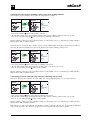
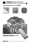
TECHNICAL DATA ZW FB 10
XXXEVFXJEF
;8'#'VOL'FSOCFEJFOVOH
#BUUFSJFY7"""
'SFRVFO[.)[
#FUSJFCTUFNQFSBUVS$$
*ODM
I Include
&YDM
E Exclude
"TTPD
-PX
#BUU
Low Battery
(status ind. for
battery)
A Associate
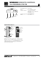
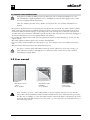
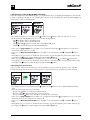
•Transmitting frequency: 868.42 MHz
•Battery:
4x 1.5 V (LR03 Micro AAA)
•Number of channels: 7 groups (theoretically the
entire network can be combined into
one group).
3 scenes, All ON/OFF
•Operating temperature: 0°C - +40 °C
•Range: up to 100 m free field
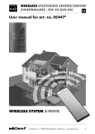
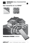
Product details ZW FB 10
Å
Up/
on
brighter
LED
(status indication)
S Status
Ç Down/off
darker
Groups
Low Battery
(status ind. for
battery)
A Associate
E Exclude
I Include
Scenes
All On/Off
On
All On
Off
All Off
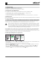
Using the remote control, several receivers / appliances can be
allocated to a choice of 7 different groups, 3 scenes that can be
configured as required, or to a central All On/Off group. Special
configuration buttons for programming are under the battery
cover on the rear of the device.
Harkortstr. 2 • 58339 Breckerfeld • Germany • www.duewi.de
II
Wireless remote control
10-channel ZW fb
GB
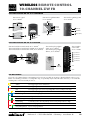
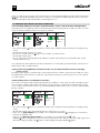
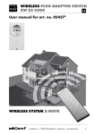
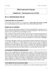
Function buttons on the düwi controller
EÔXJSFNPUFDPOUSPM
BSUOP
EÔXJXJSFMFTTXBMMUSBOTNJUUFS
BSUOP
EÔXJXJSFMFTTTXJUDIJOHDFOUSF
BSUOP
Å VQ
4 4UBUVT
Å *ODMVEF
&YDMVEF
" "TTPDJBUF
*
Ç
VQ
&
EPXO
* *ODMVEF
& &YDMVEF
" "TTPDJBUF
Ç EPXO
"MM0O
"MM0ñ
0O
0ì
" "TTPDJBUF
& &YDMVEF
* *ODMVEF
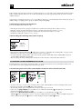
Function buttons on the düwi receiver
düwi wireless flush mounted switch, art. no. 054313
düwi wireless flush mounted dimmer 300 W, art. no. 054337
düwi wireless flush mounted shutter switch, art. no. 054368
düwi wireless plug adaptor
switch, art. no. 054375
düwi wireless plug adaptor
dimmer, art. no. 054399
düwi “Starline”
socket outlet
art. no. 125495
1 on/off slot 1
1
1 on/off slot 2
up/on
1 on/off slot 3
2
1 on/off slot 4
down/off
1 on/off slot 5
1
up/on
down/off
slot 1
slot 2
..
.
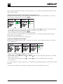
LED indications
Due to the colour LED indication on transmitters and receivers it is possible at any time to obtain feedback on the success/
failure of a switching command or a configuration step, to specifically enquire about the status of devices, or to monitor the
switching status or the functionality of devices.
:FMMPX
%FWJDFHSPVQTDFOFJTTXJUDIFEPO
#MVF
%FWJDFHSPVQTDFOFJTTXJUDIFEPñ
3FE
%FWJDFHSPVQTDFOFFSSPOFPVTDPOÙHVSBUJPOOPUTVDDFTTGVMPVUPGSBOHF
:FMMPXÚBTIJOH
%JNNFSJODSFBTJOHCSJHIUOFTT
#MVFÚBTIJOH
%JNNFSSFEVDJOHCSJHIUOFTT
(SFFO
$POÙHVSBUJPOTVDDFTTGVM
(SFFOÚBTIJOH
$POÙHVSBUJPOBDUJWF
3FEÚBTIJOH
-PXCBUUFSZJOUIFOFUXPSLDIJMEQSPUFDUJPOBDUJWFUFNQFSBUVSFUPPIJHI
3FE(SFFO
%FWJDFOPUQSPHSBNNFE
3FE:FMMPX(SFFO
%FWJDFOPUQSPHSBNNFE
Combinations are possible within a group.
Harkortstr. 2 • 58339 Breckerfeld • Germany • www.duewi.de
III
Wireless remote control
10-channel ZW fb
GB
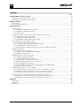
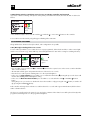
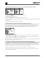
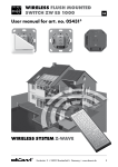
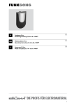
TECHNICAL drawings
1.5
70.9
10.6
4
3
45
80
+
-0 0.2
.2
6
70.9
R2
+0.1
60 -0.1
12.9
Harkortstr. 2 • 58339 Breckerfeld • Germany • www.duewi.de
IV
GB
Contents
Page
1.0 The Z-Wave® wireless system���������������������������������������������������������������������������������������������������������������������������������������6
1.1 Information on the Z-Wave wireless system��������������������������������������������������������������������������������������������������������������������� 6
1.2 Advantages of the Z-Wave wireless system��������������������������������������������������������������������������������������������������������������������� 6
2.0 General notes����������������������������������������������������������������������������������������������������������������������������������������������������������������������6
2.1 Correct use�������������������������������������������������������������������������������������������������������������������������������������������������������������������������� 6
2.2 General safety instructions������������������������������������������������������������������������������������������������������������������������������������������������ 7
3.0 User manual������������������������������������������������������������������������������������������������������������������������������������������������������������������������7
3.1 LED indications�������������������������������������������������������������������������������������������������������������������������������������������������������������������� 8
3.1.1 Overview of LED indications on the devices���������������������������������������������������������������������������������������������������������� 8
3.1.2 Advantages of the LED indications������������������������������������������������������������������������������������������������������������������������� 8
3.1.3 Delivery state������������������������������������������������������������������������������������������������������������������������������������������������������������ 8
3.2 Setting up a simple wireless network (without switching centre/server)����������������������������������������������������������������������� 8
3.2.1 Including devices in a group/scene���������������������������������������������������������������������������������������������������������������������� 8
3.2.2 Deleting/removing included devices��������������������������������������������������������������������������������������������������������������������� 9
3.2.3 Checking the switching status (status enquiry)����������������������������������������������������������������������������������������������������� 9
3.3 Resetting system components/the system������������������������������������������������������������������������������������������������������������������������� 9
3.3.1 Removing a device from the network��������������������������������������������������������������������������������������������������������������������� 9
3.3.1 Removing an additional controller from the network�����������������������������������������������������������������������������������������10
3.3.3 Deleting primary controller and network������������������������������������������������������������������������������������������������������������10
3.3.4 Deleting wireless switching centre/server as primary controller and network������������������������������������������������ 11
3.4 Expanded functions���������������������������������������������������������������������������������������������������������������������������������������������������������� 11
3.4.1 Including devices in a scene��������������������������������������������������������������������������������������������������������������������������������� 11
3.4.2 Activation of the All On/All Off functionality�����������������������������������������������������������������������������������������������������12
3.4.3 Child protection function���������������������������������������������������������������������������������������������������������������������������������������12
3.5 Working with more than one controller�������������������������������������������������������������������������������������������������������������������������13
3.5.1 Including additional controllers����������������������������������������������������������������������������������������������������������������������������13
3.5.2 Synchronising additional controllers�������������������������������������������������������������������������������������������������������������������13
3.5.3 Including devices on additional controllers��������������������������������������������������������������������������������������������������������13
3.5.4 Allocating an included device to a group/scene����������������������������������������������������������������������������������������������14
3.5.5 Connecting flush-mount modules�������������������������������������������������������������������������������������������������������������������������14
3.5.6 Connecting flush mounted modules or plug adaptors to a wall transmitter (without direct wireless connection)�������������������������������������������������������������������������������������������������������������������������������15
3.6 Managing groups/scenes on the controllers����������������������������������������������������������������������������������������������������������������15
3.6.1 Removing devices from a group/scene – devices remain in the network��������������������������������������������������������15
3.6.2 Deleting a complete group/scene – devices remain in the network���������������������������������������������������������������16
3.6.3 Removing a faulty or temporarily inactive device from a group/scene�����������������������������������������������������������16
3.7Setting up a wireless network with a wireless switching centre/server����������������������������������������������������������������������16
3.7.1Integration of a wireless switching centre/server in an existing network����������������������������������������������������������� 17
3.7.2Setting up a new network using a wireless switching centre/server������������������������������������������������������������������ 17
4.0 Annex�����������������������������������������������������������������������������������������������������������������������������������������������������������������������������������18
4.1 Warranty���������������������������������������������������������������������������������������������������������������������������������������������������������������������������18
4.2 Disposal�����������������������������������������������������������������������������������������������������������������������������������������������������������������������������18
4.3 Glossary����������������������������������������������������������������������������������������������������������������������������������������������������������������������������18
GB
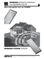
1.0 The Z-Wave® radio system
1.1 Information on the Z-Wave radio system
Z-Wave®
• Is an internationally established and defined standard for the control of wireless systems
• Is a professional, reliable and easy to operate wireless system on the interference-free frequency of 868.42 MHz
• Is future-proof and can be expanded step-by-step to form a complex system using the mutually compatible products
from the Z-Wave Alliance
Products with this logo guarantee the best possible compatibility and ensure that Z-Wave products
from other, well-known manufacturers are supported and can be integrated into existing systems.
Z-Wave® is a registered trademark of Zensys Inc. and its subsidiaries in the USA and other
countries.
1.2 Advantages of the Z-Wave wireless system
With the Z-Wave wireless system from düwi, which is based on international standards, you can conveniently and easily
switch on and off your heating and air-conditioning system, electrical appliances or your entertainment electronics.
Z-Wave offers numerous advantages over conventional wireless systems: Due to a bidirectional wireless connection
(command and reply are displayed) and the usage of multi-colour LEDs it is possible to enquire about the status of
specific devices at any time (on/off/up/down/battery charge state) or to obtain feedback of the success/failure of
switching commands or configuration steps.
Z-Wave uses interacting network nodes. The
individual receivers/appliances are connected
together and therefore form a tightly meshed
wireless network in which the signals are forwarded
to the next, neighbouring receiver. Due to this
forwarding function, individual devices act like
amplifiers. It is therefore also possible to reach
devices that are not within the immediate wireless
range of the remote control (mesh-type network
structure). As a result the system can also manage
several, alternative connections between individual
devices, the availability in the wireless network is
thus significantly increased and the susceptibility to
interference reduced.
2.0 General notes
2.1 Correct use
All Z-Wave devices are only suitable for usage in dry rooms indoors. The wireless plug adaptor switch IP44 (art. no. 054382) is also suitable for use outdoors.
All Z-Wave devices comply with the applicable European CE directives.
GB
2.2 General safety instructions
Only authorised, suitably qualified personnel are allowed to work on 230 V mains taking into account
national installation regulations/standards. Prior to installing the product, the mains supply is to be isolated
and secured against unintentional switch on.
In the case of battery-operated devices, attention is to be paid to the correct polarity of the batteries on
insertion.
• The product is only allowed to be used as intended (as described in the user manual). Any claims under the warranty
will be rendered void if changes or modifications have been made, or the devices have been painted. The product
must be immediately checked for damage on unpacking. In the event of damage, the product must not be placed in
operation under any circumstances. If hazard-free operation of the product cannot be ensured, it must be unplugged or
disconnected without delay and secured against unintentional operation.
• Do not switch any appliances that could cause injury/damage if switched on unintentionally (e.g. circular saws, lifesupport systems).
• Only switch appliances that are approved for operation at 230V/50Hz.
• Do not use wireless dimmers/switches for safety purposes (e.g. as an emergency stop or for making an emergency
call).
• Only load wireless dimmers/switches to the stated maximum power.
The device is a wireless article with Z-Wave technology. If parts of this device do not work correctly, your
safety will not be at risk, there will simply be a loss of function. In this case the devices can be switched
manually by pressing the button.
3.0 User manual
düwi wireless remote
control art. no. 054450
düwi wireless wall
transmitter
art. no. 054436
düwi wireless switching
centre/server
art. no. 054474
Every controller (e.g. remote control, wall transmitter or wireless switching centre/server) comes from the
factory with a unique identification number (ID). When additional devices are included, this ID is provided to
the other devices resulting in a coded, self-contained wireless network. This feature is advantageous if several
households in the immediate vicinity use the same system, e.g. on housing estates, in semi-detached houses or
terraced housing schemes.
GB
3.1 LED Indications
3.1.1 Overview of LED indications on the devices
You will find an overview of the various LED indications on page 2.
3.1.2 Advantages of the LED indications
As a result of the colour LED indication on the transmitters and receivers it is at all times possible
• To obtain feedback on the success/failure of switching commands or configuration steps.
• To enquire about the status of devices (on/off/up/down/battery).
• To monitor the switching status and the functionality of devices that are outside the field of view or on other floors.
3.1.3 Delivery state
During commissioning or the first time a button is pressed, the delivery state (not programmed) of the devices is indicated
by a red/green flashing LED.
3.2 Setting up a simple wireless network (without wireless switching centre/server)
This section describes the commissioning of a simple network with the basic functions on the initial usage of only one
controller (remote control or wall transmitter). For more extensive features, please see from section 3.4.
Please note that the controller (remote control, wall transmitter) that you activate first is the primary controller
that allocates a unique, interference-free address or identification number (ID) to the entire wireless network. You can only add further devices to the network using this primary controller. In the case of loss or damage to
the primary controller, the complete wireless network must be re-configured. We recommend the usage of a
remote control or a wireless switching centre/server as the primary controller.
On the installation of more complex systems, e.g. on the usage of several controllers (remote controls/wall transmitters)
we generally advise the usage of a wireless switching centre/server (art. no. 054474). It simplifies operation during
configuration, secures and co-ordinates the data in the wireless network, monitors the battery state of the devices and as
a result reduces the battery usage of other controllers (remote controls/wall transmitters).
3.2.1 (Directly) including devices in a group/scene
Controller
3x Å / Ç
LED
flashes
green
Receiver
3x 1 / 2
LED
illuminates
leuchtet
grün
green
• Press 3x within 1.5 seconds the "UP" Å or "DOWN" Ç button for the group on the remote control in which the device
is to be included.
• The LED starts to flash green and permits the inclusion of devices for 15 seconds.
• In the case of a plug adaptor press 3x within 1.5 seconds the function button ( 1 ); during this process the device
retains its last switching status ("on" or "off").
• In the case of a flush mounted module press 3x within 1.5 seconds either the "UP" 1 or "DOWN" 2 button. During this process you can choose whether the device and any connected neighbouring devices switch on (by
pressing the "UP" 1 button) or switch off (by pressing the "DOWN" 2 button).
GB
Both controller and target device indicate successful inclusion for 3 seconds with a green LED indication, failed inclusion
with a red LED indication. The device is now allocated directly to the required group. Repeat the procedure to include
additional devices. In general you can allocate a device to one or more different groups (e.g. a standard lamp can be switched in group "1"
with the dining room lighting and in group "2" with the living room lighting).
3.2.2 Deleting/removing included devices
You can undo the inclusion of devices by:
• Removing the devices from a group/scene (the device remains in the network, disassociation see 3.6.1).
• Removing a device from the network (Reset device or Exclude device from the network, see 3.3.1).
• Deleting a complete group/scene (devices remain in the network, disassociation, see 3.6.2).
• Completely resetting the system (see 3.3.1–3.3.4).
3.2.3 Checking the switching status (status enquiry)
Controller
LED
1x
indicates
zeigt
Status
an (siehe
status
(see
Umschlag
page
2)
Seite I)
S
• By pressing the related middle button S on the remote control you can display the switching status of a group on the
LED indicator on the remote control (LED indications on the cover, page I).
• To enquire about the switching status of the entire network, press the middle button in the "All On/Off" group for 2
seconds until the LED flashes green briefly. • Then an enquiry about the switching status of all devices in the network is sent and the status indicated.
3.3 Resetting system components/the system
Resetting all system components to the delivery state or a complete network reset is to be undertaken as follows; the
scope of the reset increases step-by-step in the following sections. 3.3.1 Removing a device from the network (Reset or Exclude device from the network)
Controller
LED
2 .sec.
E
flashes
blinkt
grün
green
Receiver
3x 1 / 2
LED
illuminates
leuchtet
grün
• To remove a device you can use any controller (remote control, wall transmitter or wireless switching centre/server)
• Press for 2 seconds the "Exclude" E button on the controller.
• The LED starts to flash green and permits the removal of devices for 15 seconds.
• In the case of a plug adaptor press 3x within 1.5 seconds the function button ( 1 ), during this process the device
retains its last switching status ("on" or "off").
• In the case of a flush mounted module press 3x within 1.5 seconds either the "UP" 1 or the "DOWN" 2 button. During this process you can choose whether the device and any connected neighbouring devices
switch on (by pressing the "UP" 1 button) or switch off (by pressing the "DOWN" 2 button).
GB
Both controller and target device indicate successful removal for 3 seconds with a green LED indication, failed removal
with a red LED indication.
After successful removal, the device is in the delivery state again.
3.3.2 Removing an additional controller from the network
(e.g. resetting remote control or wall transmitter)
If you do not want to reset the complete network, but just one controller (remote control or wall transmitter), proceed as
follows:
Controller 1
LED
Controller 2
2 sec
E
LED
2 sec
I
flashes
blinkt
grün
green
illuminates
leuchtet
grün
green
• Press the "Exclude" E button on your primary controller for 2 seconds (any controller in network with wireless switching
centre/server).
• The LED starts to flash green and permits the removal of the controller for 15 seconds.
• Press for 2 seconds the "Include" I button on the controller you want to remove.
Both controllers indicate successful resetting for 3 seconds with a green LED indication, failed resetting with a red LED
indication. After successful resetting, the device is in the delivery state again.
3.3.3 Deleting primary controller and network
If you have a network without a wireless switching centre/server, the complete network can be deleted with the following
steps. For a system with a wireless switching centre/server, for resetting see 3.3.4.
Controller LED
5 sec
E
Controller LED
Controller LED
3x / Å
3x / Ç
On
flashes
blinkt
grün ……
green
… flashes
blinkt
rot/gelb/
red/yellow/
grün
green
illuminates
green
• Press the "Exclude" E button on the controller for 5 seconds.
• The LED starts to flash green and changes to red/yellow/green flashing
• Press 3x within 1.5 seconds the "All On" On button (on a remote control) or "UP" Å button (on a wall transmitter).
• Press 3x within 1.5 seconds the "All Off" Off button (on a remote control) or "DOWN" Ç button
(on a wall transmitter).
• The LED starts to flash green quickly.
Successful deletion is indicated for 3 seconds with a green LED indication, failed deletion with a red LED indication.
10
GB
3.3.4 Deleting wireless switching centre/server as primary controller and network
If you have a wireless switching centre/server as the primary controller in the network, the network data are deleted as
follows:
LED
Controller
10 sec.
I
+
E
+ A flashes
red/yellow/
green
• Press simultaneously for 10 seconds the "Include"
I
+ "Exclude" E + " Associate" A buttons on the controller.
A successful reset is indicated by red/yellow/green flashing of the status LED.
3.4 Expanded functions
Along with the basic functions already described, other configurations are possible.
3.4.1 (Directly) including devices in a scene
A scene makes it possible for you to switch devices to a pre-programmed, defined value and thus to realise various light,
switch or mood scenarios (e.g. shutter half way down and lights dimmed to 60 % in the evening for watching television).
Controller
3x Å / Ç
LED
flashes
green
Receiver
3x 1 / 2
LED
illuminates
leuchtet
grün
green
• Press 3x within 1.5 seconds the "UP" Å or "DOWN" Ç button for the required scene on the remote control in which the
device is to be included.
• The LED starts to flash green and permits the inclusion of devices for 15 seconds.
• Place the device in the required switching status or to the required brightness.
• In the case of a plug adaptor press 3x within 1.5 seconds the function button ( 1 ). During this process the device will
retain its last switching status and brightness setting.
• In the case of a flush mounted module press 3x within 1.5 seconds either the "UP" 1 or "DOWN" 2 function
button.
During this process you can choose whether the device then switches on (by pressing the "UP" 1 button) or switches off
(by pressing the "DOWN" 2 button).
Both controller and target device indicate successful inclusion for 3 seconds with a green LED indication, failed inclusion
with a red LED indication.
The device is now allocated to the required scene and on the activation of the related scene will be placed directly in the
programmed switching status or to the programmed brightness.
11
GB
3.4.2 Activation of the All On/All Off functionality
To be able switch devices from different groups or scenes simultaneously (e.g. switching off all appliances on leaving the
housing or switching on all lights in case of danger), these devices can be specifically allocated to the All On/Off group
on the remote control or a wall transmitter.
Remote control
2 sec.
I
+A
On
Receiver
3x 1 / 2
/ /S
• Press simultaneously for 2 seconds the "Include" I and "Associate" A buttons on the rear of the remote control.
• On the front, in the "All On/Off" group, press one of the following buttons:
– "On" On , to add the device to the All On group
– "Off" Off , to add the device to the All Off group
– "On" On and "Off" Off together to add the device to the All On/Off group – "Status" S , to remove the device from the All On/Off group.
• In the case of a plug adaptor press 3x within 1.5 seconds the function button ( 1 ), during this process the device
retains its last switch state ("on" or "off").
• In the case of a flush mounted module press 3x within 1.5 seconds either the "UP" 1 or "DOWN" 2 function
button.
During this process you can choose whether the device and any connected neighbouring devices then switch on (by
pressing the "UP" 1 button) or switch off (by pressing the "DOWN" 2 button). • In the case of a wall transmitter press 3x within 1.5 seconds either the "UP" Å or "DOWN" Ç function button. During this process you can choose whether the devices and any connected neighbouring devices then switch on (by
pressing the "UP" Å button) or switch off (by pressing the "DOWN" Ç button).
3.4.3 Child protection function
In the case of the child protection function you can select whether it is to be possible to operate a device only after
manual "unlocking" via the buttons (sequence protection) or in general the device can only be operated wirelessly.
Controller
LED
2 sec.
I
+A
Controller
Å
flashes
blinkt
grün
green
/Ç/ S
Receiver
3x 1 / 2
• Press simultaneously for 2 seconds the "Include" I and "Associate" A buttons on the controller until the LED flashes
green. • Select the required type of protection as follows. – Group 1 "UP" Å button to deactivate the child protection
– Group 1 "Status" S button to activate the sequence protection
– Group 1 "DOWN" Ç button to be only able to operate the device wirelessly
• In the case of a plug adaptor press 3x within 1.5 seconds the function button ( 1 ), during this process you can select
whether the device is to be switched on or switched off.
• In the case of a flush mounted module press 3x within 1.5 seconds either the "UP" 1 or "DOWN" 2 function
button.
During this process you can choose whether the device and any connected neighbouring devices then switch on (by
pressing the "UP" 1 button) or switch off (by pressing the "DOWN" 2 button). 12
GB
In the case of the "Sequence" type of protection, the device can be unlocked briefly by pressing 3x the function buttons
( 1 / 2 ), the LED indication illuminates green if successful. 5 seconds after the last button press the device is protected
again automatically, the LED indication flashes red during this process.
3.5 Working with more than one controller
3.5.1 Including additional controllers (wall transmitter, remote control) Include and Replication
During this process an additional controller is included in the network using the primary controller (or in the case of the
usage of a wireless switching centre/server using any controller)
Controller 1
3x
LED
Controller 2
LED
LED
2 sec.
I
flashes
blinkt
grün
green
I
flashes
blinkt
grün
green
illuminates
leuchtet
grün
green
• Press 3x the "Include" I button on your primary controller (any controller in network with wireless switching centre/
server).
• The LED starts to flash green for 15 seconds.
• Press for 2 seconds the "Include" I button on the controller you want to include.
• The LED starts to flash green.
• As soon as the inclusion (and update) of the additional controller starts, the frequency at which the LEDs on both
controllers flash increases.
Successful inclusion of the additional controller is indicated for 3 seconds with a green LED indication on both devices,
failed inclusion with a red LED indication.
3.5.2 Synchronising additional controllers (in the case of network without wireless switching
centre/server)
As initially only the primary controller has the current network data, it is sensible to synchronise all controllers to ensure
the stable function of the network. To synchronise, repeat the the inclusion process from point 3.5.1 for each controller
you want to update.
3.5.3 Including devices on additional controllers
Here a device is registered in the network using the primary controller (or on the usage of a wireless switching centre/
server using any controller), without direct allocation to a group. The device can then also be allocated to the group/
scene on other controllers in the network, e.g. an additional wall transmitter or if the device is not to be switched via the
primary controller.
Controller
3x
LED
I
flashes
blinkt
grün
green
Receiver
3x 1 / 2
LED
illuminates
green
• Press 3x the "Include" I button on your primary controller (any controller in network with wireless switching centre/
server). • The LED starts to flash green and permits the inclusion of devices for 15 seconds.
• In the case of a plug adaptor press 3x within 1.5 seconds the function button ( 1 ), during this process the device
retains its last switching status.
• In the case of a flush mounted module press 3x within 1.5 seconds either the "UP" 1 or the "DOWN" 2 button. During this process you can choose whether the device and any connected neighbouring devices
then switch on (by pressing the "UP" 1 button) or switch off (by pressing the "DOWN" 2 button).
13
GB
Both controller and target device indicate successful inclusion for 3 seconds with a green LED indication, failed inclusion
with a red LED indication.
3.5.4 Allocating an already included device to any group/scene
(If the device is to be allocated to a scene with a defined nominal state, e.g. with a specific brightness, set to device to
this state by pressing the related function button ( 1 / 2 ).)
Controller
3x Å / Ç
LED
Receiver
flashes
blinkt
grün
green
3x 1 / 2
LED
illuminates
leuchtet
grün
• Press 3x within 1.5 seconds on the required controller the "UP" Å or "DOWN" Ç button for the required group/scene.
• The LED starts to flash green and permits the allocation of devices for a period of 15 seconds.
• Press 3x within 1.5 seconds a function button ( 1 / 2 )
on the receiving device (e.g. plug adaptor, flush mounted module). Both controller and receiving device indicate successful allocation for 3 seconds with a green LED indication, failed
allocation with a red LED indication. The device is now allocated directly to the related group. 3.5.5 Connecting flush-mount modules
The flush mounted modules make it possible to connect up to four devices, e.g. to simultaneously switch or dim several
devices simultaneously.
Controller
2 sec.
A
1x
I
Receiver
Controller
3x 1 / 2
3x Å / Ç
LED
illuminates
leuchtet
grün
green
• Press for 2 seconds the "Associate" A button on the controller of your choice. • Briefly press the "Include" I button on the same controller. • Press 3x within 1.5 seconds either the "UP" 1 or "DOWN" 2 button on the receiving device (this device is controlled
by the connected device).
• Press 3x within 1.5 seconds either the "UP" Å or "DOWN" Ç button on the controller (this device controls the
connected device).
The controller indicates successful connection for 3 seconds with a green LED indication, failed connection with a red LED
indication.
To be able also to switch the devices both ways, repeat the above procedure with the order reversed.
14
GB
3.5.6 C
onnecting flush mounted modules or plug adaptors with a wall transmitter
(if there is no direct wireless connection)
If you want to connect a wall transmitter with a flush mounted module in the network that cannot be reached directly from
a wall transmitter already installed, proceed as follows
Controller
2 sec.
A
1x
I
Receiver
Controller 2
3x 1 / 2
3x Å / Ç
• Press for 2 seconds the "Associate" A button on the controller. • Briefly press the "Include" I button on the controller.
• Press 3x within 1.5 seconds either the "UP" 1 or "DOWN" 2 button on the receiving device.
• Press 3x within 3 seconds the function button ( Å / Ç ) on the receiving device.
Please note that to operate the device at least one device that supports routing (plug adaptor, flush mounted module,
wireless switching centre/server) is required to establish a connection between the wall transmitter and the device.
3.6 Managing groups/scenes on the controllers
It is possible at any time to change the membership (allocation) of device in groups/scenes, e.g. to add or remove
individual devices from a group/scene or to reset entire groups/scenes.
3.6.1 Removing devices from a group/scene – devices remain in the network (Disassociation)
Controller
LED
2 sec.
A
flashes
blinkt
grün
green
(schnell)
(quickly)
Controller LED
Receiver
1x Ç
3x 1 / 2
flashes
blinkt
grün
green
(langs.)
(slowly)
LED
illuminates
green
• Press the "Associate" A button on the related controller for 2 seconds
(remote control/wall transmitter).
• The LED starts to flash green (quickly).
• Press the "DOWN" Ç button on the controller for the related group/scene.
• The LED starts to flash green (slowly)
• In the case of a plug adaptor press 3x within 1.5 seconds the function button ( 1 ). • In the case of a flush mounted module press 3x within 1.5 seconds either the "UP" 1 or "DOWN" 2 function
button.
The receiving device indicates successful removal for 3 seconds with a green LED indication, failed removal with a red
LED indication. The device has been removed from the group/scene and will no longer be operated or displayed.
15
GB
3.6.2 Deleting a complete group/scene – devices remain in the network (Disassociation)
Controller
LED
10 sec.
A
flashes
blinkt
red/yellow/
rot/gelb/
green
grün
Controller
1x
LED
Ç
illuminates
leuchtet
grün
green
• Press the "Associate" A button on the related controller for 10 seconds
(remote control/wall transmitter).
• The LED starts to flash red/yellow/green.
• Press the "DOWN" Ç button on the controller for the related group/scene.
The controller signals successful deletion of a group/scene for 3 seconds with a green LED indication, failed deletion with
a red LED indication.
The group/scene is now blank and can be configured again.
3.6.3 Removing a faulty or temporarily inactive device from a group/scene
If a device in a group/scene is faulty or is to be temporarily set inactive (e.g. if a plug adaptor has been removed) and
can therefore no longer be reached, after an attempt at switching or enquiring about the status the message "Device
faulty" is returned. This error message can be suppressed by automatic deactivation of the device. If this device is reactivated (e.g. if a plug adaptor is plugged in again), it is automatically reallocated to the original group/scene.
Controller
LED
10 sec.
S
illuminates
leuchtet
grün
green
• Press for 10 seconds the "Status" S button for the related group/scene on the controller, if you want to clear the status
indication for a group. • Press for 10 seconds the "Status" S button for the "All On/Off" group on the controller, if you want to clear the
complete network (e.g. in the case of the loss or destruction of a device)
The controller indicates successfull clearing of the status indication for a group or the network for 3 seconds with a green
LED indication, failed clearing with a red LED indication.
3.7 Setting up a wireless network with wireless switching centre/server
On the installation of more complex systems, e.g. on the usage of several controllers (remote controls/wall transmitters)
we generally advise the usage of a wireless switching centre/server (art. no. 054474). It simplifies operation during
configuration, secures and co-ordinates the data in the wireless network, monitors the battery state of the devices and as
a result reduces the battery usage of other controllers (remote controls/wall transmitters). In general it is possible at any time to expand an existing network with a wireless switching centre/server.
In a network with a wireless switching centre/server, it is possible to include devices in the network or remove devices
from the network using any controller.
16
GB
3.7.1 Inclusion of a wireless switching centre/server in an existing network
First include the wireless switching centre/server in the current primary controller:
Controller
3x
LED
I
Switching
server
2 sec.
I
flashes
blinkt
grün
green
LED
illuminates
green
• Press 3x the "Include" I button on the primary controller.
• The LED starts to flash green and permits the inclusion of the wireless switching centre/server for 15 seconds.
• Press for 2 seconds the "Include" I button on the wireless switching centre/server.
Wireless switching centre/server and controller indicate successful inclusion for 3 seconds with a green LED indication,
failed inclusion with a red LED indication.
Next include in succession all other controllers (remote control, wall transmitter) and battery-operated devices that were
already in the network and that were not previously known to the wireless switching centre/server.
Switching
server
3x
LED
Controller
LED
2 sec.
I
flashes
blinkt
grün
I
illuminates
leuchtet
grün
• Press 3x the "Include" I button on the wireless switching centre/server.
• The LED starts to flash green and permits the re-inclusion of the controller for 15 seconds. • Press for 2 seconds the "Include" I button on the controller.
Wireless switching centre/server and controller indicate successful inclusion for 3 seconds with a green LED indication,
failed inclusion with a red LED indication. 3.7.2 Setting up a new network using a wireless switching centre/server
First ensure all devices and controllers are in the initial state (red/green flashing LED) – see 3.3.1 (Reset device).
Switching
server
3x
LED
Controller
LED
2 sec.
I
flashes
blinkt
grün
I
illuminates
leuchtet
grün
• Press 3x the "Include" I button on the wireless switching centre/server.
• The LED starts to flash green and permits the inclusion of the wireless switching centre/server for 15 seconds.
• Press for 2 seconds the "Include" I button on the controller.
Wireless switching centre/server and controller indicate successful inclusion for 3 seconds with a green LED indication,
failed inclusion with a red LED indication.
Repeat the process with each additional controller that you want to add to the network. You can now include additional
devices in the network or allocate then to groups and scenes at any time with any included controller.
17
GB
4.0 Annex
4.1 WARRANTY
Claims under the warranty are subject to statutory provisions. Subject to technical change without notice.
• Our products are manufactured using the latest technology and are subject to strict quality control. Should,
nevertheless, defects occur on your device, düwi GmbH provides a warranty as detailed below.
• Our warranty covers the improvement or delivery of a new device if the device can be demonstrated to be defective in
relation to its function or the characteristics of the materials used.
• The warranty does neither cover natural wear and tear or transport damage, nor damage as a consequence of failure
to follow the installation instructions or improper installation. • The warranty is automatically rendered void if the device has been opened after fault diagnostics.
• The duration of the warranty is 24 months from the date of purchase of the device by the end user. Proof of purchase
by means of a bill, delivery note or similar documentation is required to prove that the warranty period has not expired.
• Batteries, lamps and rechargeable batteries supplied are excluded from the warranty.
• düwi GmbH is not liable for indirect or consequential damage, or financial losses.
4.2 Disposal
Within the EU this symbol indicates that this product is not allowed to be disposed of in household waste. Waste devices contain valuable materials that can be recycled and that should be sent for recycling to prevent
pollution or a health hazard due to the uncontrolled disposal of waste.
For this reason please dispose of waste devices via suitable collection systems or send the device to the place
you bought it for disposal. The device will then be sent for recycling.
4.3 Glossary
Include
Exclude
Associate
Disassociate
Reset
Replication
Include devices in a group/scene.
Remove a device from the network
Connect (up to four) devices together so that, e.g., several devices can be switched or dimmed
synchronously and simultaneously
Delete a complete group/scene, devices remain in the network
Reset a device or the system components to the delivery state (not programmed)
Copy the current network data to a further controller (remote control/wall transmitter/wireless
switching centre/server)
Notes on programming compatible devices from the Z-Wave Alliance from other manufacturers:
Establish
include mode
Establish
exclude mode
Associate
Reinclude/
Replicate
Disassociate
Learn Mode
Send Node
Info Frame
Add Node
Press 3x the "Include" button on the controller
Press for 2 seconds the "Exclude" button on the controller
For 2 seconds press "Associate" button on the controller, then the "UP" button on the controller
followed by "Send Node Info Frame" on the target device
Press 3x the "Include" button on the controller followed by "Send Node Info Frame" on the target
device
For 2 seconds press "Associate" button the controller, then the "DOWN" button on the controller
followed by "Send Node Info Frame" on the target device
Press 3x "UP" or "DOWN" button
(Slave) Press 3x "UP" or "DOWN" button (controller) for 2 seconds. Press "Include" button
Press 3x "UP" or "DOWN" button (inclusion or primary controller)
18