1
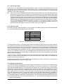
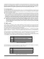
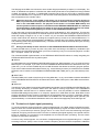
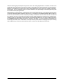
User´s Manual
FEEDBACK DESTROYER
DSP1100
English Version 1.1
May 1998
The information contained in this manual is subject to change without notice. No part of this manual may be reproduced or
transmitted in any form or by any means, electronic or mechanical, including photocopying and recording of any kind, for any
purpose, without the express written permission of Behringer GmbH.
ALL RIGHTS RESERVED © 1998 Behringer GmbH. BEHRINGER is a registered trademark.
BEHRINGER INTERNATIONAL GmbH, Hanns-Martin-Schleyer-Str. 36-38, D-47877 Willich-Münchheide II
Tel. +49 (0) 21 54 / 92 06-0, Fax +49 (0) 21 54 / 92 06-30.
1
EG-Declaration of Conformity
Spezielle Studiotechnik GmbH
acc. to the Directives
89/336/EWG and 73/23/EWG
We,
BEHRINGER INTERNATIONAL GmbH
Hanns-Martin-Schleyer-Straße 4
D - 47877 Willich
Name and address of the manufacturer or the introducer of the product on the market who is established in the EC
herewith take the sole responsibility to confirm that the product:
FEEDBACK DESTROYER DSP1100
Type designation and, if applicable, Article-No
which refers to this declaration, is in accordance with the following standards or
standardized documents:
x EN 60065
x EN 55020
x EN 61000-3-2
x EN 61000-3-3
The following operation conditions and installation arrangements have to be presumed:
acc. to Operating Manual
B. Nier, President
Name, address, date and legally binding signature of the person responsible
2
Willich, 01.03.1998
SAFETY INSTRUCTIONS
CAUTION: To reduce the risk of electrical shock, do not remove
the cover (or back). No user serviceable parts inside; refer servicing to qualified personnel.
WARNING: To reduce the risk of fire or electrical shock, do not
expose this appliance to rain or moisture.
This symbol, wherever it appears,
alerts you to the presence of
uninsulated dangerous voltage inside
the enclosure - voltage that may be
sufficient to constitute a risk of shock.
This symbol, wherever it appears, alerts
you to important operating and maintenance instructions in the accompanying
literature. Read the manual.
DETAILED SAFETY INSTRUCTIONS:
All the safety and operation instructions should be read before the appliance is operated.
Retain Instructions:
The safety and operating instructions should be retained for future reference.
Heed Warnings:
All warnings on the appliance and in the operating instructions should be adhered to.
Follow instructions:
All operation and user instructions should be followed.
Water and Moisture:
The appliance should not be used near water (e.g. near a bathtub, washbowl, kitchen sink, laundry tub, in a
wet basement, or near a swimming pool etc.).
Ventilation:
The appliance should be situated so that its location or position does not interfere with its proper ventilaton.
For example, the appliance should not be situated on a bed, sofa rug, or similar surface that may block the
ventilation openings: or placed in a built-in installation, such as a bookcase or cabinet that may impede the
flow of air through the ventilation openings.
Heat:
The appliance should be situated away from heat sources such as radiators, heat registers, stoves, or other
appliance (including amplifiers) that produce heat.
Power Source:
The appliance should be connected to a power supply only of the type described in the operating instructions
or as marked on the appliance.
Grounding or Polarization:
Precautions should be taken so that the grounding or polarization means of an appliance is not defeated.
Power-Cord Protection:
Power supply cords should be routed so that they are not likely to be walked on or pinched by items placed
upon or against them, paying particular attention to cords and plugs, convenience receptacles and the point
where they exit from the appliance.
Cleaning:
The appliance should be cleaned only as recommended by the manufacturer.
Non-use Periods:
The power cord of the appliance should be unplugged from the outlet when left unused for a long period of
time.
Object and Liquid Entry:
Care should be taken so that objects do not fall and liquids are not spilled into the enclosure through openings.
Damage Requiring Service:
The appliance should be serviced by qualified service personnel when:
- The power supply cord or the plug has been damaged; or
- Objects have fallen, or liquid has been spilled into the appliance; or
- The appliance has been exposed to rain; or
- The appliance does not appear to operate normally or exhibits a marked change in performance; or
- The appliance has been dropped, or the enclosure damaged.
Servicing:
The user should not attempt to service the appliance beyond that is described in the Operating Instructions.
All other servicing should be referred to qualifield service personnel.
3
The FEEDBACK DESTROYER
s 2-channel Digital Feedback Destroyer / Parametric EQ powered by a 24-bit high-speed DSP
s 20-bit A/D and D/A converters with 64/128 times oversampling for ultra-high headroom and resolution of
detail
s Automatically and “intelligently” searches out and destroys up to 12 frequencies per channel
s 24 fully programmable Parametric Filters that can be set manually or via MIDI
s “Set-and-forget” default setting enables immediate and super-easy feedback destroyer performance
s Single-Shot mode automatically searches and destroys feedback and remains the filter until you reset
them manually
s Auto mode continously monitors the mix, resetting programmed filters automatically
s Manual mode allows for setting up to 24 fully parametric filters including Frequency, Bandwith and Gain
s Single-Shot, Auto and Manual modes are assignable for each filter
s Two digital processing engines give you independent or coupled functions on left and right channels
s Internal 24-bit processing with professional 48 kHz sampling rate
s Full MIDI capability and user preset memories to store programs for instant recall
s Accurate eight-segment LED level meters simplify level setting for optimum performance
s “Future-proof” software-upgradeable architecture
s Future editor software (free of charge) allows for total remote control via PC
s High-quality components and exceptionally rugged construction ensures long life and durability
s Manufactured under the stringent ISO9000 management system
4
FOREWORD
Dear Customer,
Welcome to the team of FEEDBACK DESTROYER users and thank you very much for expressing your
confidence in BEHRINGER products by purchasing this unit. It is one of my most pleasant tasks to write this
letter to you, because it is the culmination of many months of hard work for our engineering team. Our daily
objective is to be focused on you, the musician and the sound engineer, and with that focus in mind, it drives
us to reach a goal which is unique, and is the backbone of the BEHRINGER philosophy.
It is our philosopy to share our joy with you, because you are the most important member of the BEHRINGER
family. With your highly competent suggestions for new products you`ve greatly contributed to shaping our
company and making it successful. In return, we guarantee you uncompromising quality (manufactured under
ISO9000 certified management system) as well as excellent technical and audio properties at an extremely
favorable price. All of this will enable you to fully unhold your creativity without being hampered by budget
constraits.
We are often asked how we can make it to produce such high-grade devices at such unbelievably low prices.
The answer is quite simple: it`s you, our customers! Many satisfied customers mean large sales volumes
enabling us to get better conditions of purchase for components, etc. Isn´t it only fair to pass this benefit back
to you? Because we know that your success is our success, too!
I would like to thank all the people, whose help on the FEEDBACK DESTROYER has made it all possible.
Everybody has made very personal constributions, starting from the designers of the unit via the many staff
members in our company to you, the user of BEHRINGER products.
Thank you and sincerely yours,
Uli Behringer
5
TABLE OF CONTENT
1. INTRODUCTION ......................................................................................................................7
1.1 Technical background .................................................................................................................... 7
1.1.1 Feedback as a physical phenomenon .................................................................................. 9
1.1.2 Graphic equalizers ............................................................................................................. 10
1.1.3 Parametric equalizers ......................................................................................................... 10
1.2 The FEEDBACK DESTROYER .................................................................................................... 10
2. THE CONCEPT ......................................................................................................................12
2.1 The quality of components and circuit .......................................................................................... 12
2.2 Two independent channels ........................................................................................................... 12
3. INSTALLATION .....................................................................................................................13
3.1
3.2
3.3
3.4
Rack mounting .............................................................................................................................
Mains voltage ...............................................................................................................................
Audio connections ........................................................................................................................
Selecting the operating level .........................................................................................................
13
13
13
14
4. CONTROL ELEMENTS .........................................................................................................15
4.1 Keys for parameter selection / jog wheel (rotary control) .............................................................. 15
4.2 Display and indicators .................................................................................................................. 16
4.3 Rear control elements .................................................................................................................. 16
5. OPERATION ..........................................................................................................................18
5.1
5.2
5.3
5.4
Activating/deactivating the filters ..................................................................................................
Manual filters / parametric equalizer .............................................................................................
Automatic filters ............................................................................................................................
Working with programs .................................................................................................................
5.4.1 Recalling programs ............................................................................................................
5.4.2 Choice of mode ..................................................................................................................
5.4.3 Editing filter parameters ......................................................................................................
5.4.4 Storing programs ................................................................................................................
5.5 MIDI control ..................................................................................................................................
5.6 The basics of digital signal processing .........................................................................................
18
18
18
18
19
19
19
20
20
21
6. APPLICATIONS .....................................................................................................................24
6.1
6.2
6.3
6.4
6.5
6.6
Using the FEEDBACK DESTROYER in the monitor path ............................................................. 24
Using the FEEDBACK DESTROYER in the main mix bus ........................................................... 24
Using the FEEDBACK DESTROYER in single channels and sub-groups .................................... 25
Using the FEEDBACK DESTROYER in a studio environment ..................................................... 26
Using the FEEDBACK DESTROYER as an effects device .......................................................... 26
Special remarks ............................................................................................................................ 26
6.6.1 Level setting ....................................................................................................................... 26
6.6.2 Digital overflow ................................................................................................................... 27
6.6.3 “Tuning in” P.A. and monitor systems ................................................................................. 27
7. FREQUENCY CHART ...........................................................................................................28
8. MIDI IMPLEMENTATION ...................................................................................................... 29
9. SPECIFICATIONS .................................................................................................................30
10. WARRANTY ......................................................................................................................... 31
6
1. INTRODUCTION
With the FEEDBACK DESTROYER you purchased a highly useful device for the control of sound reinforcement systems, which will enable you to focus your attention on what is essential: your music. The fully
featured FEEDBACK DESTROYER not only suppresses feedback but also incorporates a wealth of additional functions in one single unit. Its 24 separate filters can be edited in all parameters and automatically
detect and suppress feedback frequencies. With its pro-level internal signal processing circuitry, the unit can
also be used as a high-end equalizer for stage and studio applications. The MIDI interface allows for integrating the FEEDBACK DESTROYER into any MIDI system, and the open system architecture enables you to
update the system software whenever you want. In a word: the Behringer FEEDBACK DESTROYER was
built for the next millennium.
1.1 Technical background
The steady development of modern sound reinforcement systems has made it possible to produce almost
any level of loudness. Yet, the increase in loudness goes in line with a need for optimized audio quality.
Today, audiences expect to hear a powerful and transparent sound. Nothing can spoil a live event more than
interference and feedback.
High volume levels and the use of ever sophisticated monitor systems with a great number of speaker boxes
have increased the potential risk of feedback loops. Up to now sound engineers have used conventional 1/3octave equalizers to suppress unwanted feedback. Now, the Behringer FEEDBACK DESTROYER gives
you the option to delegate this task to the FEEDBACK DESTROYER, so that you can pay your music your
undivided attention instead of having to suppress feedback with graphic EQ’s using a trial-and-error approach.
To fully understand how the Behringer FEEDBACK DESTROYER works you will need to know the meaning
of a few fundamental terms used in signal equalization, such as:
s dB, decibel
s quality factor (Q), bandwidth
s octave, 1/3-octave
With the FEEDBACK DESTROYER, as with any other type of equalizer, the amount of boost/attenuation
applied to a specific frequency is expressed in decibels (dB). What’s a decibel? The abbreviation dB is not a
unit (although often used as one), but describes a logarithmic proportion. The entire dynamic range of human
hearing (from the threshold of audibility to a jet-airplane, see fig. 1.1) starts with about 0.00002 Pa (threshold
of audibility) and goes up to 113 Pa (threshold of pain).
The range of sound pressure levels or the dynamic range of human hearing encompasses seven times the
power of ten, which corresponds to a factor of 10,000,000. This enormous range of values is difficult to
handle and additionally does not represent the subjective perception of sound, since human hearing tends to
use a logarithmic curve. When an increase in loudness by the factor two is perceived as one step, four times
the loudness level equals two steps. So, the decibel is a unit of measurement that describes a level in relation
to a reference quantity. To make clear which reference quantity is meant, the abbreviation SPL (sound
pressure level) is sometimes used together with dB. Starting with a value of 0 dB SPL for the threshold of
audibility, any dB values can be calculated by means of the following formula:
L = 20 ⋅ log
U2
U1
whereas L = e.g. the absolute sound pressure level in dB SPL, U1 = e.g. a reference sound pressure of
0.00002 Pa, U2 = e.g. the sound pressure (in Pa) produced by the sound source to be calculated, and log =
decimal logarithm.
1. INTRODUCTION
7
Jet Engine
160
140
Sound-Pressure Level (dB SPL)
Threshold Of Pain
Power Drill
120
Machinery Hall
100
"Loud" Office
80
Normal Conversation
60
Quiet Apartment
40
Recording Studio
20
Falling Leaves
0
Threshold Of Audibility
Fig. 1.1.: Dynamic range of human hearing
As can be seen, human hearing has a very wide dynamic range of about 130 dB, which surpasses the range
of a DAT or CD player with an approximate range of 96 dB. From a physical point of view, a 6 dB boost
corresponds to an increase in loudness by the factor 2. However, the human ear perceives a signal to be
twice as loud as before only if it is boosted by about 10 dB. This will give you an idea of the variety of sound
manipulations that can be realized with the 24 filters of the FEEDBACK DESTROYER. For each filter, you
can apply a boost of +16 dB or a cut of -48 dB, i.e. you can boost the selected frequency by the subjectively
perceived factor 3 (physically x5) or attenuate it by the factor 27 (physically x250)!
The sound which an EQ produces not only depends on the selected frequency and the amount of gain
(expressed in dB); the bandwidth of the filters also plays an important role. Here, we generally use the socalled absolute bandwidth of a filter, which is measured from the lower to the upper cutoff frequency. Starting
from there, you can divide the absolute bandwidth by the filter’s center frequency to calculate the relative
bandwidth. The quality factor (Q) is simply the reciprocal value of the relative bandwidth.
Filter attenuated by 8 dB at 1kHz
0 dB
Bandwidth = 600 Hz
-2 dB
-3 dB
-4 dB
-6 dB
-8 dB
Center frequency
= 1 kHz
-10 dB
-12 dB
200 Hz
1 kHz
Fig. 1.2: Typical equalizer filter curve
8
1. INTRODUCTION
5 kHz
The filter bandwidth can also be expressed in octaves (as on the FEEDBACK DESTROYER). The following
table shows a list of decimal Q values vs. octaves:
Octa ve
1/6
1/4
1/3
1/2
3/4
1
3/2
2
3
Qua lity fa ctor (Q)
8.65
5.76
4.32
2.87
1.90
1.41
0.92
0.67
0.40
Fig. 1.1: Octaves vs. Q factors
Now the following relationship becomes clear: the higher the Q factor, the narrower the frequency band that
can be cut or boosted. On the Behringer FEEDBACK DESTROYER you can adjust the relative bandwidth
conveniently with the infinitely variable jog wheel. The filter bandwidth can be tuned from 2 octaves (120/60
octaves) down to 1/60 octave (for fine adjustments).
1.1.1 Feedback as a physical phenomenon
Almost every concert goer may have experienced with their own ears the howling and squealing of an
improperly set sound reinforcement system. Feedback is one of the main problems encountered during live
events. A feedback loop is produced when a microphone signal is reproduced by an amplifier system, to be
picked up again (with the same phase position) by the microphone. Thus, feedback is built up at all frequencies
where the distance between microphone and speaker corresponds to a multiple of the signal’s wavelength.
Speaker Box
Microphone
Mixing Console
Power Amp
Fig. 1.3: Typical feedback loop
Basically, any microphone signal passing through an amplifier is liable to generate feedback. Unfortunately,
the feedback frequencies of P.A. systems differ, and even one single system can have varying feedback
frequencies, as these depend largely on the room acoustics. Feedback can be caused by the following
conditions:
s The microphones are too close to the speaker boxes or the speakers are badly positioned (monitor
system).
s The microphone channels on the mixing console are not set up correctly.
1. INTRODUCTION
9
s The microphones used are not operated in accordance with their directivity (e.g. cardioid/super-cardioid).
s The acoustic properties of the room are unfavorable. Tiled walls and floors heavily reflect the sound.
All rooms feature a number of natural resonances sometimes with “high” quality factor. At such frequencies
the potential risk of feedback is increased. In addition to the acoustic properties of the room, the relative
position of the microphone with reference to the loudspeaker plays a decisive role for the generation of
feedback. In practice, this phenomenon can be observed with microphone held directly in front of a speaker,
thus producing feedback. Of course, the first thing to do in such a case is to move the microphone away from
the speaker. When doing so, you can hear the feedback frequency change, because a variation in the
distance between microphone and loudspeaker results in a variation of feedback frequencies. It is therefore
very difficult to anticipate feedback frequencies and avoid their occurrence by means of equalizers with fixed
settings.
1.1.2 Graphic equalizers
Graphic equalizers are part of the audio engineer’s standard equipment for live applications. In this context,
graphic EQ’s usually perform two main tasks:
s Fine tuning the mix to the room acoustics by inserting the EQ in the master inserts of the mixing console.
s To some extent, experienced audio engineers can use graphic EQ’s to manually suppress annoying
feedback.
The 1/3-octave design with 31 faders per channel has become the standard among graphic equalizers. Here,
the spacing between individual filter frequencies is 1/3 octave. The quality factor (Q) of the filters (usually 1
octave) is fixed as are the frequencies controlled with the 31 faders.
1/3-octave equalizers are very popular (e.g. our ULTRA-CURVE DSP8000) because they are so easy to
operate. The fader positions clearly show how the signal is being processed, especially since graphic EQ’s
have fixed frequencies based on the so-call ISO standard. So, all graphic equalizers designed to meet the
ISO standard feature the same fixed frequencies. Once you’ve got used to work with a 1/3-octave equalizer,
you will find the FEEDBACK DESTROYER a highly convenient tool, as it splits up the audio spectrum into the
ISO frequencies (see table 1.2), which enables you to access the most important frequencies quickly. Of
course, you can use the Fine button to fine tune the standard ISO frequencies (in1/60-octave steps) within a
range of 1/3 octave.
Hz
kHz
20
1
25 31.5 40
1.25 1.6
2
50 63 80
2.5 3.15 4
100 125 160 200 250 315 400 500 630 800
5
6.3
8
10 12.5 16 20
Table 1.2: standard ISO frequencies
1.1.3 Parametric equalizers
Parametric equalizers, unlike graphic EQ’s, allow for selecting both the processing frequency and the bandwidth, so that it is possible to process any given signal in full detail. Naturally, this equalizer design can also
be used to “filter” unwanted signals, however, only if these signal have a fixed frequency. If the frequency
changes, the parametric equalizer would have to be readjusted all the time. The majority of (analog) parametric EQ’s suffers from a quite fundamental drawback: they are operated by means of rotary controls, i.e.
contrary to graphic EQ’s, it is much more difficult to make necessary readjustments quickly.
1.2 The FEEDBACK DESTROYER
As you have seen, suppressing feedback with a graphic and/or parametric equalizer often means that you
have to accept compromises. Since feedback signals fail to comply with the standard ISO frequencies of
graphic EQ’s and additionally can have changing frequencies, their suppression with a graphic equalizer is
more or less a matter of luck.
Example: let’s assume a feedback signal at 1.8 kHz is produced during a concert. To suppress it, you’ve got
to cut the 1.8 kHz band on your EQ. However, since graphic equalizers only have 1.6 and 2 kHz bands, you
might need to attenuate both bands. Result: although feedback will be eliminated due to the low filter quality,
10
1. INTRODUCTION
you will also fade out many music signals which you’d actually wish to keep. Additionally, cutting these
midrange frequencies also means that your P.A. system loses power and performance.
In theory, a parametric EQ can be used to suppress feedback by means of high filter qualities. However, your
tweeters may well have gone up in smoke before you’ve found the frequency at which feedback occurs and
managed to eliminate it by adjusting the filter frequency, bandwidth and gain accordingly. For this reason, the
FEEDBACK DESTROYER also uses a highly optimized version of the automated, fully parametric filters we
designed for the Behringer ULTRA-CURVE. With the FEEDBACK DESTROYER your P.A. system will be
under your control again!
Unlike many conventional equalizers, the FEEDBACK DESTROYER provides an impressive range of features:
s If required, the FEEDBACK DESTROYER detects and suppresses feedback automatically by analyzing
the music signal and determining the frequency of the interference signal. Additionally, it calculates the
filter quality and attenuation necessary to fade out feedback. The entire process does not take more than
a fraction of a second and can be performed simultaneously for all 24 filters!
s The FEEDBACK DESTROYER calculates the filter quality with such a high precision that nothing but the
feedback signal will be filtered, while retaining the original music signal. This means increased P.A. headroom and a more balanced, powerful and transparent sound image.
s With the FEEDBACK DESTROYER almost all of the power delivered by the amps will reach the speakers, because the precisely set, narrow-band filters reduce energy losses to a minimum.
s The filters can be operated both in manual and automatic mode. Naturally, you can combine both modes
in single programs.
s Clearly structured entry keys give you direct access to essential parameters, while the jog wheel allows
you to conveniently adjust them as desired. Favorite settings can be stored in 10 preset programs. Of
course, the FEEDBACK DESTROYER fully integrates into any MIDI system.
s This enormous processing power is provided by a “software-separated” 24-bit Dual-Engine processor.
The FEEDBACK DESTROYER precisely converts your music with 20-bit AD/DA converters using a prolevel sampling rate of 48 kHz. The high-grade components and circuitry make sure that the quality of the
24 fully parametric EQ’s meets studio standards.
s Quick filter settings can be realized by using standard ISO values for the allocation of frequency bands.
Subsequently, you can fine tune the frequency of your choice.
1. INTRODUCTION
11
2. THE CONCEPT
2.1 The quality of components and circuit
Behringer’s philosophy guarantees both perfect circuit design and no-compromise selection of components.
A 24-bit DSP is used as the heart of the FEEDBACK DESTROYER, which is one of the best components
available owing to its outstanding specifications and excellent sonic characteristics. Top-quality 20-bit AD/
DA converters ensure the high-precision conversion of all signals. Additionally, the FEEDBACK DESTROYER
uses metal-film resistors and capacitors with very tight tolerances, high-grade switches as well as other
select components.
The FEEDBACK DESTROYER was manufactured using SMD technology (Surface Mounted Device). These
sub-miniature components known from aerospace applications not only guarantee extremely high packing
densities but als increased reliability. Additionally, the FEEDBACK DESTROYER was built to meet one of the
highest industrial standards - ISO9000.
2.2 Two independent channels
The FEEDBACK DESTROYER features two entirely separate channels to give you maximum flexibility. So,
you can use the combination algorithms of each channel for completely different applications. Due to the
“Couple“ function it is also possible to set up both channels identically.
12
2. THE CONCEPT
3. INSTALLATION
The FEEDBACK DESTROYER was carefully packed in the factory and the packaging was designed to
protect the unit from rough handling. Nevertheless, we recommend that you carefully examine the packaging
and its contents for any signs of physical damage, which may have occurred in transit.
+
If the unit is damaged, please do not return it to us, but notify your dealer and the shipping
company immediately, otherwise claims for damage or replacement may not be granted. Shipping claims must be made by the consignee.
3.1 Rack mounting
The Behringer FEEDBACK DESTROYER fits into one standard 19" rack unit of space (1 3/4"). Please allow
at least an additional 4" depth for the connectors on the back panel.
+
Be sure that there is enough air space around the unit for cooling and please do not place the
FEEDBACK DESTROYER on high temperature devices such as power amplifiers etc. to avoid
overheating.
3.2 Mains voltage
Before you connect your FEEDBACK DESTROYER to the mains, please make sure that your local
voltage matches the voltage required by the unit! The fuse holder on the female mains connector has 3
triangular markers, with two of these triangles opposing each other. Your FEEDBACK DESTROYER is set to
the operating voltage printed next to these markers, and can be set to another voltage by turning the fuse
holder by 180°. CAUTION: this instruction does not apply to export models exclusively designed, e.g.
for 115 V operation!
3.3 Audio connections
All audio inputs/outputs on the Behringer FEEDBACK DESTROYER are unbalanced. Always use shielded
cables of relatively short lengths to avoid interference problems.
+
Please ensure that only qualified persons install and operate the FEEDBACK DESTROYER. During
installation and operation the user must have sufficient electrical contact to earth. Electrostatic charges
might affect the operation of the FEEDBACK DESTROYER!
All connectors are of the 6.3-mm mono phone jack type. If you use stereo plugs, please connect sleeve and
ring.
Unbalanced Operation with 1/4" Connector
Strain Relief Clamp
Sleeve
Tip
Sleeve = GND / Shielding
Tip = Signal
Fig. 3.1 Mono phone plug
3. INSTALLATION
13
3.4 Selecting the operating level
With the „Operating Level“ switch on the rear of the Behringer FEEDBACK DESTROYER you can adjust the
internal operating level of the unit. Thus, the FEEDBACK DESTROYER can be adapted perfectly to various
levels (e.g. both the typical home recording level of -10 dBV and the professional studio level of +4 dBu). The
LED indicators on the front panel help you adjust the operating level as optimally as possible.
In order to be able to check intern overrides the LED display announces the output level of the FEEDBACK
DESTROYER. To adjust the input level, switch the device to Total Bypass mode (see 4.1) and control the
input signal in such way that the CLIP-LED does not light up.
14
3. INSTALLATION
4. CONTROL ELEMENTS
Fig. 4.1: Front panel controls elements
The Behringer FEEDBACK DESTROYER is equipped with ten parameters keys, one jog wheel (rotary control) which is used to alter the selected parameter or preset and a numeric LED display. Each of the 24 filters
has one LED assigned to it, which informs you about the status of the filter. By means of an 8-stage LED
meter each of the two fully independent channels can be monitored.
4.1 Keys for parameter selection / jog wheel (rotary control)
12
1
3
5
7
9
2
4
6
8
10
11
Fig. 4.2: Entry keys and jog wheel
1
With Filter Select activated you use the jog wheel to select one of the 12 filters per channel.
2
The Filter Mode key gives you access to the four operating modes Off, Parametric EQ (PEQ), SingleShot and Auto Mode. In addition to that you can edit the threshold of feedback suppression (-3 to -9
dB) by pressing the Filter Mode and the Gain key together for about 2 seconds.
3
Use the Engine L key to select the left audio channel.
4
Use the Engine R key to select the right audio channel. If you wish to process the left and right
channels simultaneously (Couple mode), press both Engine keys at the same time.
5
Press the Frequency key to select the frequency you wish to process. The FEEDBACK DESTROYER
splits up the adjustable frequency range (20Hz to 20 kHz) into the 31 standard ISO values of a graphic
EQ (see 1.1.2).
6
The Fine key allows you to fine tune the standard ISO frequencies (in 1/60-octave steps) within a
tuning range of 1/3 octave (-9/60 to +10/60).
7
Bandwidth determines the filter bandwidth of the selected filter. The adjustable value ranges from 2
octaves (120/60 octave) down to 1/60 octave.
8
The Gain key sets the desired boost/cut of the selected filter in dB (+16 dB/-48 dB).
9
The In/Out key allows for optional bypassing the parametric filters or all filters. By shorty pressing the
In/Out key only the parametric filters will be deactivated and the green LED ends up lighting. Hold
down the In/Out key for about two seconds to deactivate all filters. A cyclically flashing LED will indicate this Total-Bypass mode. One further pressing reactivates all filters. The LED flickers when relevant MIDI data is received.
4. CONTROL ELEMENTS
15
+
10
+
Please, use the Total-Bypass function only with utmost caution because by deactivation, the
FEEDBACK DESTROYER possibly unlocks suppressed feedbacks.
Any modifications made to a preset can be stored with the help of the Store key. Ten presets are
available on the FEEDBACK DESTROYER. Press and keep the In/Out and the Store keys for about
two seconds, the FEEDBACK DESTROYER automatically enters MIDI mode.
Press and keep the keys Filter Select and Store before powering up the FEEDBACK DESTROYER.
Then switch on the FEEDBACK DESTROYER and keep the two keys pressed for about two seconds.
The programs are counted up and reset to their original default settings.
11
Use the Power switch to switch on the FEEDBACK DESTROYER.
12
With the Jog Wheel, a continuous rotary control, you can freely change the selected parameters. Turn
the wheel clockwise to increase the values, or counter-clockwise to reduce them.
4.2 Display and indicators
16
15
13
14
Fig. 4.3: The display elements on the front panel
13
After power-up, the LED display reads the number of the preset last used. This clearly legible, 2 1/2digit numeric display has plus/minus indicators to show that parameters are incremented or decremented
in Edit mode.
14
The indicators Hz, kHz, 1/60 and dB to the right of the display light up when you change the associated
parameters in Edit mode. For example, if you raise the level of a filter, the “dB” indicator lights up. A “+”
to the left of the preset number signals that the level is being increased.
15
The FEEDBACK DESTROYER features 24 filters which can be monitored conveniently with the indicators next to the display. Twelve LEDs inform you about the status of the filters of each channel (left/
right). A bright LED announces that a filter has been set. Cyclically flashing LEDs signal seeking filters
in Single-Shot and Auto mode.
16
The level meter enables you to monitor the output level. Each channel has eight LEDs to correctly
monitor the level. A continously flickering Clip-LED informs you about possibly occuring distortion (see
5.6). If the FEEDBACK DESTROYER is set to Total Bypass mode, the level meter announces the
input level.
16
4. CONTROL ELEMENTS
4.3 Rear control elements
21
20
19
17
18
Fig. 4.4: Connectors and control elements on the rear of the FEEDBACK DESTROYER
17
Use the Operating Level switch to adapt the FEEDBACK DESTROYER to different operating levels.
You can select a -10 dBV semi-pro level used for home recording and a +4 dBu level used in professional studios. The level indicators on the front are adapted automatically to the selected nominal
level, i.e. an optimum operating range of the meters will always be assured.
18
The FEEDBACK DESTROYER was designed for operation with unbalanced mono phone jacks (6.3
mm). Each audio channel (left/right) has a phone jack for incoming signals. If you only want to use the
device with a mono input, please use the left input.
19
Also the two outputs of the FEEDBACK DESTROYER have one phone jack for each audio channel.
20
The FEEDBACK DESTROYER features extensive MIDI implementation. In addition to the standard
MIDI IN and MIDI OUT connectors, you can loop through MIDI signal by using the MIDI THRU jack.
21
Use the enclosed power cord and ICE mains connector to connect the FEEDBACK DESTROYER to
the mains power supply.
4. CONTROL ELEMENTS
17
5. OPERATION
The Behringer FEEDBACK DESTROYER can operate in four different modes. To meet more complex requirements with regard to flexible signal processing, these modes can be combined in a program.
5.1 Activating/deactivating the filters
In Off mode, the corresponding filter is deactivated and can be activated by selecting one of the modes
described below.
5.2 Manual filters / parametric equalizer
The FEEDBACK DESTROYER allows you to freely process any music signals. To raise or lower specific
frequencies in level, you can directly select these frequencies by means of the manual filters (Parametric
EQ mode). Each filter has the functionality of a fully parametric EQ, i.e. you can set the center frequency, the
quality factor (Q) and the amount of boost/cut (in dB).
5.3 Automatic filters
The FEEDBACK DESTROYERs automatic filters operate in two modes: Single-Shot and Auto mode. In
order to find a feedback, the FEEDBACK DESTROYER divides the entire frequency band into 1/60 octave
steps (20 Hz to 20 kHz) and determines the respective level of these individual bands. He compares this
value to the level of the entire signal. The difference of these levels determines whether a filter is set. The
FEEDBACK DESTROYER now provides you with the unique possibility to adapt this parameter according to
your own needs. You can edit this feedback sensitivity (see 5.4.2) within a range of -3 dB to -9 dB (in 1 dB
steps). The standard value for this parameter is -6 dB. This value provides an optimal recognition of feedback
during most applications. During e.g. a pure speech transmission, the feedback sensitivity can be lowered to
-9 dB. In this way, the algorithm would recognize and would suppress a feedback even faster. On the other
hand a higher adjustment of the feedback sensitivity (e.g. -3 dB) makes feedback suppression more stable.
In addition to that intended feedbacks (guitars or keyboards) become recognized much more slower.
Filters in Single-Shot mode automatically analyze the music signal to detect feedback frequencies. Having
detected such a frequency, the filter automatically configures its parameter to suppress feedback as efficiently as possible. As the filter is locked to the detected frequency, this mode is ideally suited to suppress
feedback having a constant frequency. Possible applications are “fixed-position” microphones (e.g. on the
drums). After the filter has adjusted itself automatically, it enters a special Lock mode, which means that
although the frequency remains fixed, the width and depth of the filter are still being adapted to the feedback
frequency, i.e. the width is increased as soon as the feedback frequency begins to shift, and the gain is cut if
feedback prevails. The gain is not reduced to prevent feedback from recurring.
All microphones that are moved during a performance (e.g. vocal mics) very often have varying feedback
frequencies. This type of feedback should be suppressed in Auto mode. As in Single-Shot mode, the filter
automatically selects an ideal setting for feedback suppression. But in Auto mode a locked filter tracks and
suppresses the feedback frequency even as it changes. The optimum frequency is selected automatically
and the filter is set to narrow-band mode so as to influence the music signal as little as possible. If your music
contains wanted feedback elements (e.g. guitar feedback), it is highly probable that these will be suppressed
too in Auto mode, because from a physical point of view it is impossible to distinguish “wanted” from “unwanted” feedback. Please read the hints given in section 6.3 to work around this situation.
5.4 Working with programs
In order to store your favorite settings, the FEEDBACK DESTROYER has ten user presets and a default
preset. All operating parameters can be stored, i.e. your programs are recalled in full detail. Of course, all
settings will be retained even after switching the FEEDBACK DESTROYER off. Owing to state-of-the-art
circuitry, no internal battery is needed, hence the memory contents will not be lost. In the default preset
(display “--”), which serves as a basis for creating your own programs, all filters remain in the parametric
mode, with bandwidth set to 1 octave, a frequency of 500 Hz and 0 dB gain.
18
5. OPERATION
5.4.1 Recalling programs
After power-up, the FEEDBACK DESTROYERs display reads the number of the preset last used. The jog
wheel allows you to conveniently select the preset of your choice. Turn the rotary control to the left to step
through the programs in descending order. Turn it to the right to increment the programs. The default preset
is located in front of the first program.
+
Please note that the FEEDBACK DESTROYER generally activates the newly selected presets only
after about one second, which is indicated by a dot in the lower right corner of the display. After loading
the data, the FEEDBACK DESTROYER enables the preset and the dot disappears. This brief interruption
avoids the direct activation of every preset, as you scroll through the preset list with the jog wheel.
Otherwise, incomplete "parameter remnants" of presets could reach the audio outputs of the FEEDBACK
DESTROYER, with possibly disastrous consequences, especially when using a high-power P.A. system.
Thus, the FEEDBACK DESTROYER makes sure that no "unwanted" programs are loaded
unintentionally. Additionally, you can rotate the jog wheel at high speed and still have the time to
specifically select the preset of your choice, instead of any of its "neighbors".
5.4.2 Choice of mode
Each filter mode has a letter assigned to it, which appears in the display after pressing the FILTER MODE
key. The following display messages can be recognized:
Display Mode of operation
O
P
A
S
L
Off
Parametric EQ
Auto
Single Shot
Locked (S)
Table 5.1: FEEDBACK DESTROYER operating modes
To change the filter mode, you first have to press the FILTER SELECT key to specify the number of the filter
(1 to 12) with the jog wheel. Using the ENGINE keys you can not only select the left or right channel, but also
both ones at the same time. Then you can choose the filter mode by simply pressing the FILTER MODE key
and turning the jog wheel. The display message “L” (locked) informs you that a filter from the Single-Shot
mode is already suppressing a feedback. You can unlock such a filter by switching it back to single mode. As
soon as a new feedback will be found, the FEEDBACK DESTROYER switches the filter from the old frequency to the new one. If you leave the Auto or Single-Shot mode and enter the Parametric mode, the filter
keeps all parameter settings.
In order to avoid an inadvertent changeover, the filter mode selection takes place after a period of approximately one second. This is indicated by a dot in the lower right corner of the display. To accelerate this
process simply press any other key.
By pressing and keeping the FILTER MODE and the GAIN key for about 2 seconds you can adjust the
feedback threshold within a range of -3 dB to -9 dB.
5.4.3 Editing filter parameters
To change filter settings, the filter has to situate in Parametric EQ mode. In this case you can adapt the center
frequency by pressing the FREQUENCY key. Depending on the frequency, either the “Hz” or “kHz” indicator
to the right of the display lights up. If you want to lift the frequency to e.g. 2700 Hz turn the jog wheel until the
ISO frequency (2.5 kHz, see table 1.2 standard ISO frequencies) closest to this value appears in the display
and the “kHz” indicator lights up. The FINE key allows you to fine tune the chosen standard ISO frequency
within a tuning range of 1/3 octave (in 1/60-octave steps). The mathematic proportion between the displayed
value and the absolute frequency, and an easy guide to quickly find the desired frequency is available in
chapter 7 (frequency chart). The bandwidth of the filter can be adjusted by selecting the BANDWIDTH key.
The adjustable bandwidth ranges from 2 octaves down to 1/60 octave. By pressing the GAIN key it is possible to set the desired boost or cut of the selected frequency. A “+” signals that the level is being increased and
a “-” signals a decreasement.
5. OPERATION
19
In Single-Shot and Auto mode it is not possible to change the filter parameters. In these modes you only are
allowed to call up the parameters. However you can convert such a filter into a parametric one with same
frequency and bandwidth, but with a gain of 0 dB. You simply have to press and keep the FILTER MODE key
for about 2 seconds. To reactivate a locked filter simply choose the Single-Shot or Auto mode.
5.4.4 Storing programs
Use the STORE key to store the program edited in section 5.4.3. Basically, all parameter changes in Parametric EQ mode can be saved. Filters working in Single-Shot or Auto mode will adjust and store the required
parameters automatically. Example:
s You recall a program for editing. Then you edit the preset as desired using the function keys and the jog
wheel. During this process, the flashing STORE key reminds you that the preset settings have been
changed but not saved yet. Press the STORE key once. The display reads the current preset number and
starts flashing. To keep the original preset, use the jog wheel to select a different preset that can be
overwritten. Press the STORE key again to save the edits to the selected preset. If you wish to overwrite
the original preset, simply press the STORE key twice (after editing) to save all changes you have made.
+
Whenever you have edited a preset and pressed the STORE key twice, all previous settings in
this preset are erased and overwritten with the new parameter values. However, if you wish to
keep the original preset, use the jog wheel to select another preset before you press the STORE
key a second time.
5.5 MIDI control
Use the MIDI key combination to select the MIDI parameters you wish to adjust. For this purpose press and
keep the IN/OUT and the STORE keys for about two seconds. All parameters can be edited with the jog
wheel and the IN/OUT key. The MIDI menu includes six pages which you can select by pressing the IN/OUT
key (forwards) and the STORE key (backwards) several times.
On the first page you can select the MIDI channel. The display reads a small “c” (= channel). The jog wheel
adjusts a channel from 1 through 16. To switch off the MIDI function simply select the “0” value (displayed as
“-”).
On the second page you can select MIDI Omni mode, i.e. the unit transmits/receives on all 16 MIDI channels.
The display reads “O” (=Omni). Use the jog wheel to activate (“1”) or deactivate (“0”) Omni mode.
The third page allows for configuring controller commands. On its right-hand side, the display reads a capital
“C” (=Controller). The jog wheel selects one of the following four controller modes:
Display
Mode
0
No controller data are transmitted
1
Controller data are received but not transmitted
2
Controller data are transmitted but not received
3
Controller data are transmitted and received
Table 5.2: Controller settings
The fourth page gives you access to the program change setup. The display reads a capital “P” (=Program).
Here, too, four modes can be selected with the jog wheel, as follows:
Display
Mode
0
No program change data are transmitted
1
Program change data are received but not transmitted
2
Program change data are transmitted but not received
3
Program change data are transmitted and received
Table 5.3: Program change settings
20
5. OPERATION
The fifth page of the MIDI menu shows the “store enable“ flag represented by a capital „S“ in the display. The
value “0” disables the reception of controller #18, and therefore protects the user presets from being modified
via MIDI. Accordingly, the value “1” enables MIDI controller #18 so that you can modify or replace presets
with a remote MIDI device or a sequencer. In this case the actual settings will be stored directly to the location
that corresponds to the controller value.
+
Attention! Since the “store enable“ mode allows you to access memory locations directly via
MIDI, it is possible that stored presets will be replaced or altered if controller #18 messages are
sent on the same MIDI channel. The purpose of this mode is to facilitate MIDI backup and
restore operations without express confirmation at the FEEDBACK DESTROYER. It is therefore
recommended to disable (flag=0) this mode as soon as the intended data transfer has ended.
This is done automatically when you switch off the FEEDBACK DESTROYER.
On the sixth page you will find the Bulk Dump menu, which is indicated by a “0d” in the display. This function
enables you to backup all presets to an external sequencer and to write them back again. By turning the jog
wheel the display changes to “1d” or “2d”. In mode “1d” you can switch the FEEDBACK DESTROYER to
receive mode. Mode “2d” allows for sending the complete memory content to an external MIDI device. To
confirm your choice simply press the flashing STORE key. Floating dots in the display indicate a readiness
and a flickering IN/OUT key signals MIDI activity. To leave the receive mode and to abrupt the sysex receiving
simply press any other key.
+
During a bulk dump all audio functions of the FEEDBACK DESTROYER will be deactivated.
To leave the MIDI menu you have to press a key which does not belong to the MIDI key combination (the
MIDI mode is canceled automatically when you have not made any entry on one of the six pages for a certain
time - exception: modes “1d” and “2d”).
The full-featured MIDI implementation of the FEEDBACK DESTROYER allows for easily integrating the
FEEDBACK DESTROYER into any MIDI system.
s MIDI IN
Any MIDI data sent to the FEEDBACK DESTROYER (sequencer, MIDI footswitch, etc.) are received via the
MIDI IN jack. For example, if you wish to use the FEEDBACK DESTROYER as an effects device for your
guitar rack, you can connect the MIDI IN jack to a MIDI footswitch that allows for selecting program presets.
If your rack includes another MIDI effects device (e.g. a multi-effects processor), the data sent from the MIDI
footswitch can be routed via the FEEDBACK DESTROYERs MIDI THRU jack to your multi-effects processor.
s MIDI THRU
The MIDI THRU jack is used to loop through incoming MIDI data, i.e. any control data received at the MIDI IN
of the FEEDBACK DESTROYER will be transmitted via the MIDI THRU jack to other MIDI devices/instruments.
s MIDI OUT
The MIDI OUT jack allows for transmitting MIDI data that originate from the FEEDBACK DESTROYER. We
are currently developing a software editor which will allow for storing single items of the FEEDBACK
DESTROYER`s internal data on an external medium. Thus, it will be possible to archive FEEDBACK
DESTROYER settings and presets on a computer, sequencer or MIDI data recorder. Both MIDI Control
Change and MIDI Program Change commands will be transmitted when you edit or recall filter settings.
Detailed information on this future software editor are available from our Behringer hotline (Germany: tel.
(0)2154-920666), our international distributors and/or our Internet homepage http://www.behringer.de.
5.6 The basics of digital signal processing
To convert continuous analog signals into a series of digital words, a so-called “Analog to Digital Converter”
(ADC) is used. The converter functions by viewing the signal entering it a given number of times over a period
of time, e.g. 44100 times per second, giving a rate of 44.1 kHz, and in each case measuring the signal
amplitude, and giving it a numerical value. This form of measuring the signal regularly over a period of time is
known as “sampling”, the conversion ot the amplitude into a numerical value, quantizing. The two actions
together are referred to as digitizing.
In order to carry out the opposite - the conversion of a digitized signal into its original analog form - a “Digital
to Analog Converter” (DAC) is used. In both cases the frequency at which the device operates is called the
5. OPERATION
21
sampling rate. The sampling rate determines the effective audio frequency range. The sampling rate must
always be more than twice the value of the highest frequency to be reproduced. Therefore, the well known
CD sampling rate of 44.1 kHz is slightly higher than twice the highest audible frequency of 20 kHz. The
accuracy at which quantization takes place is primarily dependent on the quality of the ADCs and DACs
being used.
The resolution, or size of a digital word used (expressed in bits), determines the theoretical “Signal to Noise
ratio” (S/N ratio) the audio system is capable of providing.
The number of bits may be compared to the number of decimal places used in a calculation - the greater the
number of places, the more accurate the end result. Theoretically, each extra bit of resolution should result in
the S/N ratio increasing by 6 dB. Unfortuanetly, there are a considerable number of other factors to be taken
into account, which hinder the achievement of these theoretical values.
If you picture an analog signal as a sinusoidal curve, then the sampling procedure may be thought of as a grid
superimposed on the curve. The higher the sampling rate (and the higher the number of bits), the finer the
grid. The analog signal traces a continuous curve, which very seldom coincides with the cross points of the
grid. A signal level at the sampling points will be assigned a digital value, usually the one closest to the exact
representation. This limit to the resolution of the grid gives rise to errors, and these errors are the cause of
quantizing noise. Unfortuanetly, quantizing noise has the characteristic of being much more noticeable and
unpleasant to the ear than “natural” analog noise.
U (Voltage)
Quantization Steps
8
Continuous
Analog Signal
0111
7
0110
6
0101
5
0100
4
0011
3
0010
0001
0000
-8
-7
-6
-5
-4
-3
-2
1111
1110
2
3
4
5
6
7
8
t (Time)
-2
1101
Quantization Errors
(Noise)
1
-1
1100
1011
1010
-3
-4
-5
-6
1001
-7
1000
-8
Digital Words
Conversation Rate
Fig. 5.1: Transfer diagram for an ideal linear ADC (2´s complement represantation)
In a digital signal processor (such as the one in the FEEDBACK DESTROYER) the data will be modified in a
number of ways. In other words, various calculation or processes will be done in order to achieve the desired
effect on the signal.
This gives rise to further errors, as these calculations are approximations, due to their being rounded off to a
defined number of decimal places. This causes further noise. To minimize these rounding off errors, the
calculation must be carried out with a higher resolution than that of the digital audio data being processed (as
a comparison, an electronic calculator may operate internally with a greater number of decimal places than
can be shown on its display). The DSP in the FEEDBACK DESTROYER operates with a 24 bit resolution.
This is accurate enough to reduce quantizing noise to levels which are usually below the audible threshold.
However, when using extreme equalizer settings, some quantizing side effects may be detected.
Digital sampling has one further, very disturbing effect: It is very sensitive to signal overload.
22
5. OPERATION
Take the following simple example using a sine wave. If an analog signal starts to overload, it results in the
amplitude of the signal reaching a maximum level, and the peaks of the wave starting to get compressed, or
flattened. The greater the porportion of the wave being flattened, the more harmonics, audible as distortion,
will be heard. This is a gardual process, the level of distortion as a percentage of the total signal rising with
the increase of the input signal level.
Digital distortion is quite different, as illustrated by this oversimplified example: If we take the situation where
a 4 bit word has the positive maximum value of 0111, and add to it the smallest possible value of 0001 (in
other words, the smallest increase in amplitude possible), the addition of the two results is 1000 - the value of
the “negative” maximum. The value is turned on its head, going instantly from positive max to negative max,
resulting in the very noticeable onset of extremely unpleasant signal distortion. Due to an intelligent algorithm
the FEEDBACK DESTROYER prevends such “turning on the head”. A occuring overflow is replaced by the
maximally permissible value. This solution corresponds to the peak-limiter and clipping technique in analog
audio engineering. In this way new distortions result, however with less disturbing character.
5. OPERATION
23
6. APPLICATIONS
The Behringer FEEDBACK DESTROYER features a high level of flexibility not only in the field of feedback
elimination. The following chapter describes some other possible applications for your FEEDBACK
DESTROYER.
6.1 Using the FEEDBACK DESTROYER in the monitor path
Inserting the FEEDBACK DESTROYER into the monitor path of your mixing console gives you maximum
protection against annoying feedback. Monitor systems are particularly susceptible to feedback because on
stage there are usually lots of microphones and speakers located in close proximity to each other. Vocal mics
are especially critical in this context as their levels must be relatively high to be able to “compete” with other
instruments. Additionally, vocal mics are not always used at fixed positions (see 1.1.1). It has therefore
proven useful to protect the monitor paths against feedback. An agreeable side effect when using the
FEEDBACK DESTROYER in the monitor path is the positive influence on both sound and loudness of the
monitors, because filtering interference makes the monitor sound more transparent and feedback suppression
enables you to increase the volume level of the monitors (which is usually highly welcomed by the musicians
performing on stage).
P.A. System
Monitor System
Monitor Out
Master Out
Fig. 6.1: Using the FEEDBACK DESTROYER in the monitor path
6.2 Using the FEEDBACK DESTROYER in the main mix bus
The FEEDBACK DESTROYER can also be used to process main mix signals. Please consider the following
remarks:
Using the FEEDBACK DESTROYER in the main mix bus gives you the advantage that any feedback occurring
in the individual microphone channels can be eliminated with just one FEEDBACK DESTROYER. However,
this also means that “wanted” feedback (e.g. guitar feedback) will be suppressed, too. Furthermore, the
FEEDBACK DESTROYER could cause a slight manipulation of the main mix sound in extreme situations.
Before applying the FEEDBACK DESTROYER, it is therefore advisable to remove the condition causing the
feedback problems. For example, try different microphone positions! Use the FEEDBACK DESTROYER in
24
6. APPLICATIONS
the monitor path and in single channels with critical signals. If there is no other way to eliminate feedback, you
can insert the FEEDBACK DESTROYER into the main mix bus. Unless your mixing console has dedicated
insert points for the main mix bus, you can simply connect the FEEDBACK DESTROYER between mixing
console and power amp. If required, adapt the levels with the Operating Level switch (see 3.4).
Wire the unit as shown below:
P.A. System
Master Out
Fig. 6.3: Using the FEEDBACK DESTROYER in the main mix bus
6.3 Using the FEEDBACK DESTROYER in single channels and sub-groups
If you want to make sure that deliberately produced feedback signals, such as “guitar feedback”, are not
eliminated, you should try inserting one or several FEEDBACK DESTROYER`s into single channels (e.g.
vocal mics) which are susceptible to feedback. Or, you could use the sub-groups of your mixing console by
routing any channels susceptible to feedback (e.g. all vocal mics) to one or several sub-groups. Thus, all less
critical signals (e.g. line signals, lower-level instrumental microphones) can pass through the mixing console
unaltered, while only the critical microphone channels are monitored from the FEEDBACK DESTROYER. In
this way, you can protect your P.A. system against feedback and still use “wanted” feedback signals.
6. APPLICATIONS
25
P.A. System
Channel
Insert
Sub-Group
Insert
Master Out
Fig. 6.2: Inserting the FEEDBACK DESTROYER in single channels and sub-groups
6.4 Using the FEEDBACK DESTROYER in a studio environment
With its highly flexible configuration the FEEDBACK DESTROYER also delivers good results in a professional
studio or home recording environment, as it provides a maximum of twelve fully parametric equalizers per
channel in Parametric EQ mode. Thus, you can realize any application ranging from slight processing to the
total manipulation of music signals. For example, you can use the FEEDBACK DESTROYER as an equalizer
for your studio monitors or to enhance the EQ’s in your mixing console, as these are often only semi-parametric.
6.5 Using the FEEDBACK DESTROYER as an effects device
With its MIDI interface the FEEDBACK DESTROYER can also be used as a programmable EQ - as a control
unit in a guitar rack or in combination with a keyboard. If you own a MIDI footswitch with an expression pedal,
you can produce interesting wah-wah effects by modifying the filter frequency with the expression pedal
while playing. A similar effect is produced when the FEEDBACK DESTROYER is used to generate “sweeping” sounds. Emphasize or de-emphasize a particular frequency and change the filter frequency continuously via MIDI. The resulting effect sound like a heavily modulating phaser (although the phasing effect is a
different phenomenon from a physical point of view). The advantage in this application is that the sweeping
sound is MIDI-controllable and can be synchronized to, for instance, a sequencer. This effect is very popular
in dance and techno music.
6.6 Special remarks
6.6.1 Level setting
Take care to set the FEEDBACK DESTROYER levels correctly! Low levels deteriorate the dynamics of the
music signal, which results in a poor, weak and noisy sound. On the other hand, excess levels overdriving
the converters in the FEEDBACK DESTROYER should also be avoided. Digital distortion is (unlike its analog
counterpart) very unpleasant as it does not occur gradually but abruptly.
To adjust the input level, switch the device to Total Bypass mode (see 4.1) and control the input signal in
such way that the CLIP-LED does not light up. Use the input level meter of the FEEDBACK DESTROYER to
adjust the input signal to about 0 dB.
26
6. APPLICATIONS
6.6.2 Digital overflow
When using the FEEDBACK DESTROYER as a parametric equalizer (Parametric EQ mode) and applying
extreme attenuation values in the low end range of the frequency spectrum (below 50 Hz), you should
perhaps set several filters to process the same frequency. Depending on the amount of attenuation applied,
the use of only one filter may lead to internal memory overflow, which produces interference in the signal
path. This is a natural physical phenomenon which should be avoided. Use for example two filters adjusted
to a signal attenuation of about -12 dB (with the same frequency and bandwidth). This produces the same
effect achieved with one filter set to -24 dB.
6.6.3 “Tuning in” P.A. and monitor systems
With the FEEDBACK DESTROYER you can improve the protection against feedback even before the show
begins, by “tuning in” your sound reinforcement system: after the system has been set up completely, open
all microphone channels and activate Single-Shot mode on your FEEDBACK DESTROYER. Then, slowly
move up the monitor and master faders until feedback comes in. Without the FEEDBACK DESTROYER you
could not increase the volume level of your system any further. With your FEEDBACK DESTROYER, however, you can considerably enhance the system headroom! Move the faders further up, and the first feedback signal will be suppressed by the FEEDBACK DESTROYER. Continue to move up the faders until about
three or four filters are suppressing various feedback signals. Subsequently, cut back the volume to the level
required for the show. In this way, you can be sure that there is enough system headroom should it be
necessary to raise the volume level during the concert.
If you have more than one FEEDBACK DESTROYER for the monitor path, you should use these devices to
protect critical signal paths. Experience has shown that musicians want to have the volume of their instrument increased on the monitor as the concert goes on. With the FEEDBACK DESTROYER you can turn up
the volume without having to fear feedback problems. When the show begins you should set several filters to
Auto mode in order to suppress feedback produced by “moving” (vocal) microphones. In Auto mode, the
FEEDBACK DESTROYER automatically tracks and suppresses feedback signals with varying frequencies.
6. APPLICATIONS
27
7. FREQUENCY CHART
In order to maintain a better survey only every second value is registered in the table. The adjustable values do
not exactly fit into a 1/60 octave intervall, because also the ISO frequencies do not perfectly fit into a physical
1/3 octave intervall. Rather a linear approximation is used to specify the values.
Background
f1,f2, ...
ISO frequency
1 third = 20/60 octave (idealized ISO interval)
increment
Display
-9/60
-8/60
-6/60
(f
n +1
− fn
)
20
-2/60
ISO
+2/60
+4/60
+6/60
+8/60
+10/60
24
30.2
38.3
48
60
77
96
120
153
24.5
30.9
39.2
49
62
78
98
123
157
20
25
31.5
40
50
63
80
100
125
160
20.5
25.7
32.4
41
51
65
82
103
129
164
21
26.3
33.2
42
53
66
84
105
132
168
21.5
27
34.1
43
54
68
86
108
136
172
22
27.6
34.9
44
55
70
88
110
139
176
22.5
28.3
35.8
45
57
71.5
90
113
143
180
20
25
32
40
50
63
80
100
125
160
Hz
Hz
Hz
Hz
Hz
Hz
Hz
Hz
Hz
Hz
188
235
296
375
470
591
749
940
1175
1495
192
240
302
383
480
604
766
960
1200
1530
196
245
309
392
490
617
783
980
1225
1565
200
250
315
400
500
630
800
1000
1250
1600
205
257
324
410
513
647
820
1025
1285
1640
210
263
332
420
526
664
840
1050
1320
1680
215
270
341
430
539
681
860
1075
1355
1720
220
276
349
440
552
698
880
1100
1390
1760
225
283
358
450
565
715
900
1125
1425
1800
.20
.25
.32
.40
.50
.63
.80
1.00
1.25
1.60
kHz
kHz
kHz
kHz
kHz
kHz
kHz
kHz
kHz
kHz
1880
2350
2955
3745
4700
5910
7490
9400
11750
14950
18800
1920
2400
3020
3830
4800
6040
7660
9600
12000
15300
19200
1960
2450
3085
3915
4900
6170
7830
9800
12250
15650
19600
2000
2500
3150
4000
5000
6300
8000
10000
12500
16000
20000
2050
2565
3235
4100
5130
6470
8200
10250
12850
16400
2100
2630
3320
4200
5260
6640
8400
10500
13200
16800
2150
2695
3405
4300
5390
6810
8600
10750
13550
17200
2200
2760
3490
4400
5520
6980
8800
11000
13900
17600
2250
2825
3575
4500
5650
7150
9000
11250
14250
18000
2.0
2.5
3.2
4.0
5.0
6.3
8.0
10.0
12.5
16.0
20
kHz
kHz
kHz
kHz
kHz
kHz
kHz
kHz
kHz
kHz
kHz
20
25
32
40
50
63
80
100
125
160
Hz
Hz
Hz
Hz
Hz
Hz
Hz
Hz
Hz
Hz
22.8
28.6
36.2
45.5
57
72.4
91
114
144
23
28.9
36.6
46
58
73
92
115
146
23.5
29.6
37.5
47
59
75
94
118
150
.20
.25
.32
.40
.50
.63
.80
1.00
1.25
1.60
kHz
kHz
kHz
kHz
kHz
kHz
kHz
kHz
kHz
kHz
182
228
286
362
455
572
724
910
1138
1443
184
230
289
366
460
578
732
920
1150
1460
2.0
2.5
3.2
4.0
5.0
6.3
8.0
10.0
12.5
16.0
20
kHz 1820
kHz 2275
kHz 2858
kHz 3618
kHz 4550
kHz 5715
kHz 7235
kHz 9100
kHz 11375
kHz 14425
kHz 18200
1840
2300
2890
3660
4600
5780
7320
9200
11500
14600
18400
-4/60
∆ fn =
Tab. 7.1: frequency chart
28
7. FREQUENCY CHART
Display
8. MIDI IMPLEMENTATION
Function
Basic
Channel
Transmitted Recognized
Default
Changed
Default
Messages
Altered
Mode
Note Number
Velocity
After Touch
True Voice
Note ON
Note OFF
Key´s
Ch´s
OFF, 1 - 16
OFF, 1 - 16
1,2,3,4
X
X
X
X
X
X
X
X
X
O 10 - 19
O (0-9)
1-10
O
X
X
X
X
X
X
X
X
X
Pitch Bender
Control
Progr.
Change
True #
System Exclusive
Song Pos
System
Song Sel
Common
Tune
System
Clock
Real Time
Commands
Local ON/OFF
Aux
All notes OFF
Messages
Active Sense
Reset
Notes
O = YES, X = NO
Mode 1:
OMNI ON, POLY
Mode 2:
OMNI ON, MONO
Mode 3:
OMNI OFF, POLY
OMNI OFF, MONO
Mode 4:
OFF, 1 - 16
OFF, 1 - 16
1,2,3,4
X
X
X
X
X
X
X
X
X
O 10 - 19
O (0-9)
1-10
O
X
X
X
X
X
X
X
X
X
Remark s
memorized
see add. Table
Tab. 8.1: MIDI implementation chart
P arameter N ame
D is play R ange
F ilter S elect
1..12
F ilter M o de
O, P , A , S
E ngine
M idi Co ntro l
N umber
10
Co ntro l Value
R ange
L eft
R ight
0
1
2
IN o n
IN o ff
IN flas hing
2
1
0
0..11
11
0..3
12
0,1,2
0..30
F requency
20 (H z)..20 (k H z)
13
F ine (1/60 Oct)
-9..+10
14
0..19
B andwidth
1..120
15
0..119
0..64
Gain
-48..+16
16
F eedback T hres ho ld
-9..-3
17
0..6
S to re
1..10
18
0..9
19
0..2
In/Out
LE Ds
Co uple
Tab. 8.2: Controller functions with MIDI
8. MIDI IMPLEMENTATION
29
9. SPECIFICATIONS
Analog Inputs
Type
Impedance
Nominal Operating Level
Max. Input Level
1/4” (6.3 mm) TRS unbalanced
100 kOhms
-10dBV to +4dBu
+16 dBu
Analog Outputs
Type
Impedance
Max. Output Level
Bandwidth
THD+N @ 1kHz / +10 dBu
S/N Ratio @ 1 kHz / +10 dBu
Crosstalk @ 1kHz
1/4” (6.3 mm) TRS unbalanced
100 Ohms
+16 dBu
20 Hz to 20 kHz (+0/-0.5 dB)
0.01 %
98 dB
80 dB
MIDI Interface
Type
Implementation
5-Pin-DIN-Socket IN / OUT / THRU
Refer to MIDI Implementation Chart in Chapter 7
Digital Processing
Converters
Sampling Rate
20-bit Sigma-Delta, 64/128-times Oversampling
48 kHz
Feedback Destroyer
Type
Filter
Frequency Range
Bandwidth
Attenuation
Time required to
eliminate feedback
DSP-controlled Digital Signal Analysis
12 independent, digital Notch Filters per channel
20 Hz to 20 kHz, adjustable in steps of 1/60 octave
2/60 to 12/60 octaves, dependent on the characteristic of the feedback
Up to -48 dB, depending on the gain of the feedback
< 0.5 sec, typical at 1 kHz
Parametric Equalizer
Type
Frequency Range
Bandwidth
Gain
12 independent filters per channel
20 Hz to 20 kHz, adjustable in steps of 1/60 octave
1/60 to 2 octaves, adjustable in steps of 1/60 octave
+16 to -48 dB in steps of 0.5 dB
Display
Type
2 1/2-digit numeric LED-Display
Power Supply
Mains Voltages
Fuse
Power Consumption
Mains Connection
Physical
Dimensions (H * W * D)
Net Weight
Shipping Weight
USA/Canada
~ 120 V AC, 60 Hz
U.K./Australia
~ 240 V AC, 50 Hz
Europe
~ 230 V AC, 50 Hz
General Export Model
~ 100-120 V AC, ~ 200-240 V AC, 50-60 Hz
100-120 V AC: 125 mA (slow-blow)
200-240 V AC: 63 mA (slow-blow)
10 Watts
Standard IEC receptacle
1 3/4” (44.5 mm) * 19” (482.6 mm) * 7 1/2” (190.5 mm)
2 kg
3.2 kg
BEHRINGER is constantly striving to maintain the highest professional standards. As a result of these efforts, modifications may be
made from time to time to existing products without prior notice. Specifications and appearance may differ from those listed or
shown.
30
9. SPECIFICATIONS
10. WARRANTY
§ 1 WARRANTY CARD
To be protected by this warranty, the buyer must complete and return the enclosed warranty card (signed/
stamped by retail dealer) within 14 days of the date of purchase to BEHRINGER INTERNATIONAL (address
see § 3). Failure to return the card in due time (date as per postmark) will void any extended warranty claims.
§ 2 WARRANTY
BEHRINGER INTERNATIONAL warrants the mechanical and electronic components of this product to be free
of defects in material and workmanship for a period of one (1) year from the original date of purchase, in
accordance with the warranty regulations described below. If any defects are found in the materials or workmanship, or if the product fails to function properly within the specified warranty period, BEHRINGER INTERNATIONAL shall, at its sole discretion, either repair or replace the product. If the warranty claim proves to be
justified, the product will be returned freight prepaid by BEHRINGER INTERNATIONAL within Germany. Outside of Germany, the product will be returned at the buyer’s expense.
Warranty claims other than those indicated above are expressly excluded.
§ 3 RETURN AUTHORIZATION NUMBER
To obtain warranty service, the buyer must call BEHRINGER INTERNATIONALH during normal business hours
BEFORE returning the product (Tel.: (0) +49 21 54 / 92 06-0). All inquiries must be accompanied by a description of the problem. BEHRINGER INTERNATIONAL will then issue a return authorization number. The product
must be returned in its original shipping carton, together with the return authorization number, to the following
address:
BEHRINGER INTERNATIONAL GmbH
Service Department
Hanns-Martin-Schleyer-Str. 36-38
D - 47877 Willich-Münchheide
Shipments without freight prepaid will not be accepted.
§ 4 WARRANTY REGULATIONS
Warranty services will be furnished only if the product is accompanied by an original retail dealer’s invoice. Any
product deemed eligible for repair or replacement by BEHRINGER INTERNATIONAL under the terms of this
warranty will be repaired or replaced within 30 days of receipt of the product at BEHRINGER INTERNATIONAL.
If the product needs to be modified or adapted in order to comply with applicable technical or safety standards
on a national or local level, in any country which is not the country for which the product was originally
developed and manufactured, this modification/adaptation shall not be considered a defect in materials or
workmanship. The warranty does not cover any such modification/adaptation, irrespective of whether it was
carried out properly or not. Under the terms of this warranty, BEHRINGER INTERNATIONAL shall not be held
responsible for any cost resulting from such a modification/adaptation. Free inspections, maintenance/repair
work and replacement of parts are expressly excluded from this warranty, if caused by normal wear of the
product.
Damages/defects caused by the following conditions are not covered by this warranty:
s misuse, neglect or failure to operate the unit in compliance with the instructions given in the user or service
manuals.
s connection or operation of the unit in any way that does not comply with the technical or safety regulations
applicable in the country where the product is used.
s damages/defects that are caused by force majeure or by any other condition beyond the control of
BEHRINGER INTERNATIONAL.
Any repair carried out by unauthorized personnel will void the warranty. Products which do not meet the terms
of this warranty will be repaired exclusively at the buyer’s expense. BEHRINGER INTERNATIONAL will inform
10.WARRANTY
31
the buyer of any such circumstance. If the buyer fails to submit a written repair order within 4 weeks after
notification, BEHRINGER INTERNATIONAL will return the unit C.O.D. with a separate invoice for freight and
packing. Such cost will also be invoiced separately when the buyer has sent in a written repair order.
§ 5 WARRANTY TRANSFERABILITY
This warranty is extended exclusively to the original buyer (customer of retail dealer) and is not transferable to
anyone who may subsequently purchase this product. No other person (retail dealer, etc.) shall be entitled to
give any warranty promise on behalf of BEHRINGER INTERNATIONAL.
§ 6 CLAIM FOR DAMAGES
Failure of BEHRINGER INTERNATIONAL to provide proper warranty service shall not entitle the buyer to claim
(consequential) damages. In no event shall the liability of BEHRINGER INTERNATIONAL exceed the invoiced
value of the product.
§ 7 OTHER WARRANTY RIGHTS
This warranty does not exclude or limit the buyer’s statutory rights provided by national law, in particular, any
such rights against the seller that arise from a legally effective purchase contract.
32
10.WARRANTY