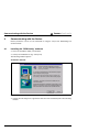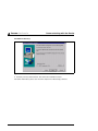
1
Leuze electronic
Barcode Positioning System BPS 37
Technical Description
© All rights reserved, especially the right of reproduction, distribution and translation. Copying or
reproductions in any form require the written consent of the manufacturer.
Changes reflecting technical improvements may be made.
Leuze electronic
Table of contents
1
General Information ........................................................................................................... 4
1.1
Explanation of Symbols ....................................................................................................... 4
1.2
Declaration of Conformity .................................................................................................... 4
2
Safety Notices .................................................................................................................... 5
2.1
Safety Standards ................................................................................................................. 5
2.2
Intended Use........................................................................................................................ 5
2.3
Working Safely ..................................................................................................................... 6
3
Description ......................................................................................................................... 8
3.1
BPS 37 device construction ................................................................................................. 8
3.2
Application ........................................................................................................................... 8
3.3
Function ............................................................................................................................... 8
3.4
Advantages .......................................................................................................................... 9
3.5
Standalone operation ........................................................................................................... 9
4
Technical Data.................................................................................................................. 11
4.1
General Specifications BPS 37 .......................................................................................... 11
4.2
LED indicators.................................................................................................................... 12
4.3
Dimensioned and Connection Drawings ............................................................................ 12
5
Accessories / Order Designation ................................................................................... 14
5.1
Accessories........................................................................................................................ 14
5.1.1
5.1.2
5.1.3
Connection units .......................................................................................................................... 14
Fastening Accessories................................................................................................................. 16
Connection cable ......................................................................................................................... 16
6
Installation ........................................................................................................................ 17
6.1
Storage, Transportation ..................................................................................................... 17
6.2
Mounting ............................................................................................................................ 17
6.2.1
Device Arrangement .................................................................................................................... 19
6.3
Connection ......................................................................................................................... 22
6.3.1
6.3.2
6.3.3
6.3.4
Connecting the BPS 37 (SSI) ...................................................................................................... 22
Connection SSI interface ............................................................................................................. 23
Connection of switching input and output .................................................................................... 25
Wire Lengths and Shielding......................................................................................................... 26
6.4
Disassembling, Packing, Disposing ................................................................................... 26
7
Commissioning ................................................................................................................ 27
7.1
Measures to be performed prior to the initial commissioning............................................. 27
7.2
Function Test ..................................................................................................................... 27
7.3
Setting the Parameters ...................................................................................................... 27
7.3.1
7.3.2
Parameter sets ............................................................................................................................ 28
Service Operating Mode .............................................................................................................. 28
Leuze electronic
BPS 37
1
Leuze electronic
Table of contents
8
Operation .......................................................................................................................... 29
8.1
Display Elements ............................................................................................................... 29
9
Communicating with the Device..................................................................................... 30
9.1
Installing the "BPSConfig" software ................................................................................... 30
9.2
Overview of Commands and Parameters .......................................................................... 32
9.2.1
9.2.2
General ’Online’ Commands ........................................................................................................32
General parameter structure ........................................................................................................33
10
Maintenance ..................................................................................................................... 34
10.1
General Maintenance Information...................................................................................... 34
10.2
Repairs, Servicing.............................................................................................................. 34
2
BPS 37
Leuze electronic
Leuze electronic
Figure 2.1:
Figure 3.1:
Figure 3.2:
Figure 3.3:
Table 4.1:
Figure 4.1:
Figure 4.2:
Table 5.1:
Figure 5.1:
Figure 5.2:
Figure 6.1:
Figure 6.2:
Figure 6.3:
Figure 6.4:
Table 6.1:
Figure 6.5:
Figure 6.6:
Figure 6.7:
Table 6.2:
Figure 7.1:
Figure 9.1:
Figure 9.2:
Figures and tables
Example for the attachment of the sticky label with warning notices ........................... 7
BPS 37 device construction ......................................................................................... 8
Connection BPS "Stand alone" .................................................................................. 10
BPS connection with connection unit MA 4.7............................................................. 10
General Specifications ............................................................................................... 12
Dimensioned drawing BPS 37.................................................................................... 12
Scanning curve BPS 37 ............................................................................................. 13
Accessories / Order Designation................................................................................ 14
Connection unit MA 4.7/MA 4D.7 / dimensioned drawing .......................................... 15
Mounting device BT 56............................................................................................... 16
Mounting example BPS 37......................................................................................... 18
Beam outlet on the BPS 37 ........................................................................................ 20
Application example ................................................................................................... 21
BPS 37 sub-D pin assignments.................................................................................. 22
Connection description BPS 37.................................................................................. 23
Connection with MA ................................................................................................... 23
Connection BPS direct ............................................................................................... 24
Connection diagram switching inputs and outputs BPS 37........................................ 25
Wire Lengths and Shielding ....................................................................................... 26
Connecting the service interface to a PC or terminal ................................................. 29
Installation window ..................................................................................................... 30
Installation directory ................................................................................................... 31
Leuze electronic
BPS 37
3
Leuze electronic
General Information
1
General Information
1.1
Explanation of Symbols
The symbols used in this operating manual are explained below.
Attention!
Pay attention to passages marked with this symbol. Failure to heed this information can lead
to injuries to personnel or damage to the equipment.
Attention Laser!
This symbol warns of possible danger through hazardous laser radiation.
Notice!
This symbol indicates text passages containing important information.
1.2
Declaration of Conformity
The barcode positioning system BPS 37 and the optional connection units MA 4.7/MA 4D.7
have been developed and manufactured under observation of the applicable European
standards and directives.
Notice!
The corresponding declaration of conformity can be requested from the manufacturer.
The manufacturer of the product, Leuze electronic GmbH & Co KG in D-73277 Owen/Teck,
possesses a certified quality assurance system in accordance with ISO 9001.
4
BPS 37
Leuze electronic
Leuze electronic
2
Safety Notices
2.1
Safety Standards
Safety Notices
The barcode positioning system BPS 37 and the optional connection units MA 4.7/MA 4D.7
have been developed, produced and tested subject to the applicable safety standards. They
correspond to the state of the art.
2.2
Intended Use
Attention!
The protection of personnel and the device cannot be guaranteed if the device is operated
in a manner not corresponding to its intended use.
Barcode positioning systems of the type BPS 37 are optical measuring systems which use
visible red laser light to determine the position of the BPS relative to a permanently mounted
barcode band.
Typically, the BPS is mounted on a (rail-)guided vehicle whose position is to be exactly
determined.
The position is determined to within a millimetre using the information of the fixed barcode
band and made available to the primary system at a suitable interface.
The optional connector and interface units MA 4.7/MA 4D.7 are intended for the easy
connection of barcode positioning systems of type BPS 37.
• rooms with explosive atmospheres
• operation for medical purposes
Areas of application
The barcode positioning system BPS 37 with optional connection unit MA 4.7/MA 4D.7 has
been designed particularly for the following fields of application:
•
•
•
•
•
High-bay storage devices and lifting gear
Crane systems
Side-tracking skates
Transfer machines
Telpher lines
Leuze electronic
BPS 37
5
TNT 35/7-24V
In particular, unauthorised uses include:
Leuze electronic
Safety Notices
2.3
Working Safely
Attention Laser Radiation!
The barcode positioning system BPS 37 operates with a red light laser of class 2 acc.
to EN 60825-1 (2001/11). It also complies with the U.S. 21 CFR 1040 regulations for a
class II product. If you look into the beam path over a longer time period, the retina of
your eye may be damaged!
Never look directly into the beam path!
Do not point the laser beam of the BPS 37 at persons!
When mounting and aligning the BPS 37, take care to avoid reflections of the laser
beam off reflective surfaces!
The use of operating and adjusting devices other than those specified in this technical description, carrying out of differing procedures, or improper use of the barcode
positioning system may lead to dangerous exposure to radiation!
The use of optical instruments or devices in combination with the device increases
the danger of eye damage!
Adhere to the applicable legal and local regulations regarding protection from laser
beams acc. to EN 60825-1 in its latest version.
The BPS 37 uses a laser diode with low power in the visible red light range with an
emitted wavelength of about 650nm. The output power of the laser beam at the reading window is at most 1.8 mW acc. to EN 60825-1 (2001/11).
The reading window is the only opening through which the laser radiation can escape
from the device. The housing of the BPS 37 is sealed and has no parts that need to
be adjusted or maintained by the user. The device must not be tampered with and
must not be changed in any way!
Notice!
It is important that you attach the sticky labels supplied to the device (notice signs and laser
emission symbol)! If the signs would be covered due to the installation situation of the
BPS 37, attach them close to the BPS 37 such that reading the notices cannot lead to looking into the laser beam!
6
BPS 37
Leuze electronic
Leuze electronic
Safety Notices
Attention!
Access to or changes on the device, except where expressly described in this operating
manual, is not authorised.
Safety regulations
Observe the locally applicable legal regulations and the rules of the employer’s liability insurance association.
Qualified personnel
Mounting, commissioning and maintenance of the device must only be carried out by qualified personnel.
Electrical work must be carried out by a certified electrician.
Leuze electronic
BPS 37
7
TNT 35/7-24V
Figure 2.1: Example for the attachment of the sticky label with warning notices
Leuze electronic
Description
3
Description
Information on technical data and characteristics can be found in chapter 4.
3.1
BPS 37 device construction
Dovetail fastening
grooves
Laser-beam
beam hole
15-pin sub-D
connector on the
underside of the
unit
4 fastening threads M3 on the
rear of the device
Figure 3.1: BPS 37 device construction
3.2
Application
Anywhere systems are moved automatically, it is necessary to correctly determine their
positions. This is achieved using various measurement techniques. In addition to mechanical measurement sensors, optical methods are particularly well suited for determining positions as they operate without mechanical wear and slippage.
Unlike other optical measurement methods, the barcode positioning system is not restricted
to linear movements. It can also be used flexibly in curved systems. Anywhere the longwearing barcode band can be attached, it is possible to use the BPS to determine the position to within a millimetre.
Guide tolerances of the system play no roll as the permitted separation between band and
BPS allows for large deviations in distance.
8
BPS 37
Leuze electronic
Leuze electronic
3.3
Description
Function
The BPS uses visible red laser light to determine its position relative to the barcode band.
This essentially takes place in three steps:
1.
2.
3.
Reading a code on the barcode band
Determining the position of the read code in the scanning area of the laser beam
Calculating of the position to within a millimetre using the code information and the
code position
The position value is then passed on via the standardised SSI interface (synchronous serial
interface) to the drive system of the vehicle for which the position is to be determined.
3.4
Advantages
3.5
Standalone operation
The barcode positioning system BPS 37 is operated as a single "stand alone" device. The
BPS features a 15-pin sub-D connector for the electrical connection of the supply voltage,
the interface and the switching inputs.
With connection units
The connection units simplify the electrical installation of the barcode positioning system in
stand-alone operation.
Moreover, they store the operating parameters so that the configuration data are retained
even if the BPS is replaced and can show parameters and operating data on a display
(MA 4D.7).
A listing of the available connection units and associated short descriptions can be found in
chapter 5. Separate data sheets are available that contain further details about the connection units.
Leuze electronic
BPS 37
9
TNT 35/7-24V
• Easy installation and commissioning
• Teach function for the "zero point", i.e. it is not necessary to exactly affix the barcode
band.
• Data output via SSI interface; BPS can be connected instead of a conventional rotation encoder.
• The function of the BPS makes it possible to attach the barcode band only at those
locations where it is necessary that the position be known exactly.
• Positioning of non-linear movements as well
• No referencing necessary following voltage drop
• Thanks to the large scanning depth, it is possible to compensate for mechanical tolerances.
• It is possible to exactly determine positions from distances of 10000 metres.
Leuze electronic
Description
Without connection unit MA 4.7/MA4D.7
Voltage supply
10 … 30 V DC
SI
SO
SSI
15 pin sub-D
connector,
socket version
Figure 3.2: Connection BPS "Stand alone"
With connection unit MA 4.7/MA4D.7
BPS 37
MA 4.7/MA 4D.7
SO
SI
Power
SSI
SSI
Connection cable
KB031-3000
Figure 3.3: BPS connection with connection unit MA 4.7
10
BPS 37
Leuze electronic
Leuze electronic
Technical Data
4
Technical Data
4.1
General Specifications BPS 37
Measurement data
Reproducible accuracy
Integration time
Measurement value output
Refresh time
Scanning depth
Electrical data
Interface type
(standard setting)
Laser diode 650nm
1000scans/sec.
±1 (2) mm
16 (8) ms
500 values/sec.
90 … 170 mm
Ports
LED green
Operating voltage
Power consumption
SSI (RS422)
electrically isolated
bits 0 … 24: data bits with position value
bit 25:
error bit
resolution: 1mm
800 kHz max. clock frequency
output of positive and negative position values
gray coded
RS232 with fixed data format,
9600Bd, 8 data bits, no parity, 1 stop bit
1 switching output, 1 switching input
device ready (Power On)
10 … 30V
3.2 W
Mechanical data
Protection class
Weight
Dimensions (W x H x D)
Housing
IP 65
400 g
120 x 90 x 43mm
diecast aluminium
Service interface
TNT 35/7-24V
Optical Data
Light source
Scanning rate
Environmental data
Operation w/o optics heating
Operation with optics heating
Storage
Air humidity
Vibration
0°C … +40°C
(BPS 37 S M 100)
-30°C … +40°C (BPS 37 S M 100 H)
-20°C … +60°C
max. 90% rel. humidity, non-condensing
IEC 68.2.6
IEC 68.2.27 (shock)
IEC 801
Electromagnetic compatibility acc. to IEC 60947-5-2
Leuze electronic
BPS 37
11
Leuze electronic
Technical Data
Barcode band
Max. length (measurement
length)
Ambient temperature
Mech. properties
Table 4.1:
10000m
-40°C … +120°C
scratch and wipe resistant
UV resistant
moisture resistant
partly chemical resistant
General Specifications
Notice!
Two models of the BPS 37 are available:
4.2
BPS 37 S M 100
BPS 37 S M 100 H
without optics heating
with optics heating
LED indicators
An internal LED indicates in the reading window whether or not the supply voltage is present.
4.3
Dimensioned and Connection Drawings
BPS 37 S M 100 / BPS 37 S M 100 H
Rear view
Plan view
Figure 4.1: Dimensioned drawing BPS 37
12
BPS 37
Leuze electronic
Leuze electronic
Technical Data
Scanning curve BPS 37
BPS 37
80
60
Reading field width [mm]
40
20
Working range
0
-20
-40
-60
-80
0
25
50
75
100
125
150
175
200
225
250
Reading distance in mm
TNT 35/7-24V
Figure 4.2: Scanning curve BPS 37
Leuze electronic
BPS 37
13
Leuze electronic
Accessories / Order Designation
5
Accessories / Order Designation
5.1
Accessories
Notice!
Products from Leuze electronic GmbH & Co KG can be ordered from any of the sales and
service offices listed on the back page of this operating manual.
Designation
Part No.
Short Description
MA 4.7
500 37324
Connection unit for BPS 37 with parameter memory
MA 4D.7
500 37325
Connection unit for BPS 37 with parameter memory
and display
BT 56
500 27375
Mounting device with dovetail for rod
KB 031-3000
500 35355
Connection cable between BPS and MA,
length: 3m
BPSConfig
500 60298
Programming software
Table 5.1:
5.1.1
Accessories / Order Designation
Connection units
Notice!
The connection units are described here in brief only. For further information regarding the
connection units please refer to the relevant data sheets
Connection unit MA 4.7/MA 4D.7
The connection units MA 4.7/MA 4D.7 are used to simplify the electrical installation of the
BPS 37. They have the following advantages compared to the installation of the BPS 37 as
a standalone device:
•
•
•
•
•
•
Terminals for switching inputs and outputs, including supply voltage
9-pin sub-D plug for service interface
Operating mode switch: service operation/standard operation
Code types - changeover switches binary/Gray
Rotary switch for setting the resolution
Parameter memory for the BPS - the BPS can be exchanged without the need for
reconfiguration.
• Display (MA 4D.7 only)
14
BPS 37
Leuze electronic
Leuze electronic
TNT 35/7-24V
Accessories / Order Designation
Figure 5.1: Connection unit MA 4.7/MA 4D.7 / dimensioned drawing
Leuze electronic
BPS 37
15
Leuze electronic
Accessories / Order Designation
5.1.2
Fastening Accessories
The mounting unit BT 56 is available for mounting the BPS 37. It is designed for rod installation.
Mounting device BT 56
Clamping jaws for
mounting on the BPS
Clamp profile for
mounting to round or
oval pipes
Ø 16 … 20mm
Figure 5.2: Mounting device BT 56
5.1.3
Connection cable
A special connection cable is available for the connection between BPS and connection
units. This connection cable may be used for the connection units MA 4.7 as well as for
MA 4D.7.
16
BPS 37
Leuze electronic
Leuze electronic
6
Installation
6.1
Storage, Transportation
Installation
Attention!
When transporting, package the device so that it is protected against collision and humidity.
Optimal protection is achieved when using the original packaging. Heed the required environmental conditions specified in the technical data.
Unpacking
© Check the packaging for any damage. If damage is found, notify the post office or shipping agent as well as the supplier.
© Check the delivery contents using your order and the delivery papers:
•
•
•
•
delivered quantity
device type and model as indicated on the nameplate
accessories
operating manual
© Save the original packaging for later storage or shipping.
If you have any questions concerning your shipment, please contact your supplier or your
local Leuze electronic sales office.
© Observe the local regulations regarding disposal and packaging.
© Clean the glass window of the BPS 37 with a soft cloth before mounting. Remove all
packaging remains, e.g. carton fibres or Styrofoam balls.
Attention!
Do not use aggressive cleaning agents such as thinner or acetone for cleaning the device
and the barcode band.
6.2
Mounting
Accessories
The mounting system BT 56 is available for installation. It may be ordered separately from
Leuze electronic. For order numbers, see table 5.1 "Accessories / Order Designation" on
page 14.
Leuze electronic
BPS 37
17
TNT 35/7-24V
Cleaning
Leuze electronic
Installation
Mounting the BPS 37
There are two basic types of mounting arrangements for the BPS 37:
• using the dovetail groove and the corresponding mounting accessories
(see figure 6.1)
• using the fastening threads on the back- and underside of the devices (chapter 4.3)
Mounting example BPS 37
Mounting device
BT 56
Figure 6.1: Mounting example BPS 37
Mounting MA
You can mount all connection units individually through the holes located on the mounting
plate (see figure 5.1).
Subsequently, connect the BPS 37 with the connection unit via the respective cable (see
chapter 5.1.3).
18
BPS 37
Leuze electronic
Leuze electronic
6.2.1
Installation
Device Arrangement
Selecting a mounting location
In order to select the right mounting location, several factors must be considered:
• The scanning range determined from the scanning curve must be adhered to at all
locations at which a position determination is to be made
• The BPS should be mounted inclined 10° from vertical towards the barcode band to
ensure that the read results are reliably obtained even if the barcode band is soiled.
10˚
0 0 2 804
0028 08
002812
002816
002 8 20
0028 24
TNT 35/7-24V
0 0 2 8 00
Notice!
The best functionality is obtained when:
• the BPS is guided parallel to the band
• the permitted working range is not exited
Notice!
On the BPS 37, the beam is not emitted perpendicular to the cover of the housing, but with
an angle of 10° towards the top. This angle is intended to prevent total reflection on the barcode band.
Leuze electronic
BPS 37
19
Leuze electronic
Installation
Minimum separation
(see scanning curve)
Figure 6.2: Beam outlet on the BPS 37
Mounting location
© When selecting a mounting location, pay attention to
• maintaining the required environmental conditions (humidity, temperature),
• possible soiling of the reading window due to liquids, abrasion by boxes, or packaging
material residues.
• lowest possible chance of damage to the scanner by mechanical collision or jammed
parts.
20
BPS 37
Leuze electronic
Leuze electronic
Installation
Application example
12
0 28
12
0002
812
0002
812
0002
8
Figure 6.3: Application example
Leuze electronic
BPS 37
21
TNT 35/7-24V
0 28
Leuze electronic
Installation
6.3
Connection
Attention!
Never open the device yourself, as this may compromise protection class IP 65.
Before connecting the device, be sure that the supply voltage agrees with the value printed
on the nameplate.
Connection of the device and maintenance work while under voltage must only be carried
out by a qualified electrician.
The power supply unit for the generation of the supply voltage for the BPS 37 and the respective connection units must have a secure electrical insulation through double insulation
and safety transformers according to DIN VDE 0551 (IEC 742).
Be sure that the earthing conductor is connected correctly. Error-free operation is only guaranteed when the device is properly earthed.
If faults cannot be corrected, the device should be removed from operation and protected
against possible use.
6.3.1
Connecting the BPS 37 (SSI)
BPS 37 sub-D pin assignments
GND
SSI clockSWOUT1
SWIN1
SSI Data+
RXD/Serv
SSI DataTXD/Serv
Reserved
Reserved
SSI clock+
Reserved
/Serv
GND
VIN
Figure 6.4: BPS 37 sub-D pin assignments
22
BPS 37
Leuze electronic
Leuze electronic
Installation
Wiring description
6.3.2
Pin 1
GND
Ground reference RS 232
Pin 2
SWIN1
Switching input 1 (+12 … 30VDC)
Pin 3
SSI data+
SSI data line
Pin 4
SSI data-
SSI data line
Pin 5
Reserve
Pin 6
SSI clock+
SSI clock line
Pin 7
/Serv
Bridge to pin 15: service operation via RS232 interface
Pin 8
VIN
Supply voltage +10 … 30VDC
Pin 9
SSI clock-
SSI clock line
Pin 10
SWOUT1
Switching output 1 (max. 100mA)
Pin 11
RXD/Serv
RXD signal, service interface RS 232
Pin 12
TXD/Serv
TXD signal, service interface RS 232
Pin 13
Reserve
Pin 14
Reserve
Pin 15
GND
Table 6.1:
Connection description BPS 37
Supply voltage 0VDC
Connection SSI interface
Connection with MA
Control/drive
SSI interface
TNT 35/7-24V
MA 4.7/MA 4D.7
Terminals
SSI DATA + 1/2
SSI DATA -
Connection 1
3/4
SSI Clock +
13
SSI Clock -
7
SSI DATA +
SSI DATA -
Connection 2
SSI Clock +
SSI Clock -
Figure 6.5: Connection with MA
Leuze electronic
BPS 37
23
Leuze electronic
Installation
Connection BPS direct
BPS 37 SM 100
Control/drive
SSI interface
Pin
SSI DATA +
3
SSI DATA -
4
SSI Clock +
6
SSI Clock -
9
Connection 1
SSI DATA +
SSI DATA -
Connection 2
SSI Clock +
SSI Clock -
Figure 6.6: Connection BPS direct
Notice!
Ensure adequate shielding. Connections 1 and 2 must be twisted pairs and the total connection line must be shielded and grounded at one end.
Attention!
It is absolutely necessary to connect the protective conductor, since all electrical interference (EM pick-up) is discharged via the protective conductor connection.
Connection of the protective conductor PE
BPS 37 without cable KB 031-3000:
connect PE to the housing of the BPS 37 or to the
housing of the 15-pin SUB-D connector!
BPS 37 with cable KB 031-3000:
connect PE to the wire with bl/wh colour coding or
connect it to the shield!
BPS with cable and MA 4.7 (MA 4D.7): connect PE to PIN 21 or PIN 22!
24
BPS 37
Leuze electronic
Leuze electronic
6.3.3
Installation
Connection of switching input and output
The BPS 37 is provided with a switching input and a switching output. The connection of the
switching input and output is made according to figure 6.7:
2
SWIN1
12 … 30 V DC
max. 100 mA
10
8
SWOUT1
VIN
10 … 30 V
DC
15
GND
Figure 6.7: Connection diagram switching inputs and outputs BPS 37
In the standard setting you can use the switching input connection SWIN1 to reset the output
of the position measurement data to zero by applying a voltage of 12 … 30VDC between
SWIN1 (pin 2) and GND (pin 15).
Switching output
The switching output connection between SWOUT1 (pin 10) and GND (pin 15) is normally
open. In the standard setting, SWOUT1 is closed in the event of a positioning error.
You can configure the switching inputs and outputs according to your needs, using the
supplied BPSConfig program.
Leuze electronic
BPS 37
25
TNT 35/7-24V
Switching input
Leuze electronic
Installation
6.3.4
Wire Lengths and Shielding
The following maximum lengths for wires and the type of shielding to be used must be
observed:
Connecting
Max. wire length
Shielding
BPS 37 - Service
RS 232
10m
absolutely required, shield
meshing
BPS 37/MA 4.7 Host
SSI
1200m
absolutely required, flexible
leads as twisted pairs and
shielded
Switching input
10m
not necessary
Switching output
10m
not necessary
Table 6.2:
6.4
Interface
Wire Lengths and Shielding
Disassembling, Packing, Disposing
Repacking
For later re-use, the device is to be packed so that it is protected against shocks and dampness. Optimal protection is achieved when using the original packaging.
Notice!
Electrical scrap is a special waste product! Observe the locally applicable regulations regarding disposal of the product.
26
BPS 37
Leuze electronic
Leuze electronic
Commissioning
7
Commissioning
7.1
Measures to be performed prior to the initial commissioning
© Before commissioning, familiarise yourself with the operation and configuration of the
device(s)!
© Before switching on, recheck all connections and ensure that they have been properly
made.
7.2
Function Test
"Power On" test
After connecting the operating voltage, the BPS 37 performs an automatic "Power On" function test. Subsequently, the green LED lights up in the optics window of the BPS 37.
Interface
Proper function of the interface can be tested easiest in service operation using the service
interface with the "BPSConfig" programming software and a notebook computer. For order
numbers, see table 5.1 on page 14.
Online commands
Using the ’Online’ commands, important device functions can be checked, e.g. proper functioning of the laser.
Should a problem persist after checking all electrical connections and settings on the
devices and host, please contact a Leuze service office near you (see the back page of this
operating manual).
7.3
Setting the Parameters
You have now commissioned the BPS. Usually, you will have to configure it before you can
use it. Using the parameter options made available by the BPS, you can configure the BPS
to suit your individual area of application. For instructions regarding the various setting
options refer to chapter 9 or to the online help of the BPSConfig program.
The setting is usually accomplished by using the program BPSConfig, see "Installing the
"BPSConfig" software" on page 30.
To understand what is happening during the parameter setting, the following chapter 7.3.1
briefly explains the various parameter sets.
The setting of the parameter sets then takes place in the operating mode "service", which is
described in chapter 7.3.2.
Leuze electronic
BPS 37
27
TNT 35/7-24V
Problems
Leuze electronic
Commissioning
7.3.1
Parameter sets
In the BPS 37 three different parameter sets are administered:
• parameter set with the default settings in the ROM
• current parameter set in the EEPROM
• working copy of the current parameter set in the RAM
Before a parameter set is loaded into the memory of the BPS 37 processor, the validity of
the parameter set is verified using checksums.
Factory default parameter set
This parameter set contains the default settings made ex works for all BPS 37 parameters.
It is permanently stored in the ROM of the BPS 37. The parameter set with the default
settings is loaded into the memory of the BPS 37,
• the first time the device is commissioned after delivery
• following the command "Factory Default" in the parameterisation program
• if the checksums of the current parameter set are invalid.
Current parameter set
In this parameter set, the current settings for all device parameters are stored. When the
BPS 37 is in operation, the parameter set is stored in the EEPROM of the BPS 37. The
current set can be stored:
• by copying a valid parameter set from the host computer
• by means of an off-line set-up with the PC set-up program BPSConfig
The current parameter set is loaded into the memory of the BPS 37:
• each time the supply voltage is connected
• following a software reset
The current parameter set is overwritten by the parameter set with the default settings:
• by a parameter reset, see "Online commands" on page 27
7.3.2
Service Operating Mode
Setting the required parameters is carried out easiest in the 'Service' operating mode. The
Service operating mode makes the following defined operating parameters available on a
separately wired RS232 interface, independent from the BPS's configuration for standard
operation:
•
•
•
•
•
•
28
transfer rate 9600 baud
no parity
8 data bits
1 stop bit
prefix: STX
postfix: CR, LF
BPS 37
Leuze electronic
Leuze electronic
Operation
Service interface active
The service interface is activated via a bridge between the pins 7 and 15 on the 15-pin subD connector. If the BPS 37 is operated with a connection unit, the service interface is activated through a switch in the connection unit.
Connection
You can connect a PC or terminal to the BPS 37 via the serial interface and configure the
BPS 37 through this connection. For this, you need a crossed RS 232 connection cable (null
modem cable) that provides the connections RxD, TxD and GND. The hardware handshake
at the service interface is via RTS. A CTS handshake is not supported.
If the BPS is connected to a connection unit, you can use the 9-pin sub-D service connector
in the connection unit. For the respective connection specifications please refer to the data
sheet of the connection unit.
Service Operating Mode
Service
15 GND
12 TxD
11 RxD
PC
BPS
TNT 35/7-24V
Figure 7.1: Connecting the service interface to a PC or terminal
8
Operation
8.1
Display Elements
On the BPS 37 there is an LED. It signals that the BPS is ready for operation.
Leuze electronic
BPS 37
29
Leuze electronic
Communicating with the Device
9
Communicating with the Device
Device parameters can be set via commands or using the easy-to-use "BPSConfig 3.0"
control software.
9.1
Installing the "BPSConfig" software
© Place the installation CD in your CD drive.
© Call up the installation file (e.g. Set-up.exe)
The following window appears:
Installation window
Figure 9.1: Installation window
© Confirm the following licence agreement and select the installation path in the following
window:
30
BPS 37
Leuze electronic
Leuze electronic
Communicating with the Device
Installation directory
Figure 9.2: Installation directory
© Confirm your entry with Continue, then follow the installation routine.
TNT 35/7-24V
For further information, please see the online help for the "BPSConfig" software.
Leuze electronic
BPS 37
31
Leuze electronic
Communicating with the Device
9.2
Overview of Commands and Parameters
Online commands can be used to send commands directly to the device for control and
configuration.
For this, the BPS 37 has to be connected to a host or service computer via the serial interface. The commands can be sent either via the host or the service interface.
9.2.1
General ’Online’ Commands
Command
Description
M+
Activating the measurement
M-
Deactivating the measurement
MI
Reversing the count direction
With the standard setting, the calculation is performed back from the max.
measurement length (10000 metre)
Set pre-set value
x = T = value is stored temporarily
(the value is erased after switching on and off)
x = D = value is stored permanently in the EPROM
MNx=yzzzzzzz
y = sign for pre-set value
zzzzzzz = specification of the pre-set value in mm
Example: MND=+0001000
Current position is set permanently to +1000 mm.
32
MNR
Deactivates the pre-set value. The unformatted measurement value is
output.
MMxyyyy
Controls the data output via the service interface
x = S = a measurement value is output (Single Shot Mode); subsequent
specification of the time not necessary
x = T = measurement values are output cyclically; time must be subsequently specified
y = time specification in ms
Example: MMT0500
Measurement values are output via the service interface in a time interval
of 500ms
MM-
Deactivating the function MMTyyyy
If the cyclical output via the service interface is no longer required, the
function must be deactivated using the command MM.
PC20
Resetting all parameters in the BPS 37 to Leuze default values.
Version query
BPS 37
Leuze electronic
Leuze electronic
9.2.2
Communicating with the Device
General parameter structure
Using the BPSConfig program, parameters can be changed via the service interface. These
parameters are divided into individual folders.
The following folders are available:
Measurement Value
Control
Measurement Value
Preparation
The various setting options are contained in the folder Measurement
Value Control. These are used for
activating or deactivating the measurement process.
Measurement Value
Monitoring
Switching output
Measurement value ranges can be
defined in this folder. If the measurement values rise above or drop
below these values, the BPS should
respond appropriately.
In this folder the activation and
deactivation as well as the timing of
the switching output are defined.
SSI Interface
Settings can be made in this folder
for controlling how the BPS reacts
to the application of a 24 V signal.
BPS 37
TNT 35/7-24V
Switching input
Leuze electronic
This folder contains the parameters
which can be used to prepare the
measurement value. This includes
e.g. setting the initial or pre-set
value, the scaling setting, the counting direction or the resolution.
This folder contains all settings necessary for integrating the BPS to a
control or drive system via an SSI
interface.
33
Leuze electronic
Maintenance
10
Maintenance
10.1
General Maintenance Information
Usually, the barcode positioning system BPS 37 does not require any maintenance by the
operator.
Cleaning
Should it become soiled, clean the glass window of the BPS 37 with a soft cloth.
Notice!
Do not use aggressive cleaning agents such as thinner or acetone for cleaning the device.
10.2
Repairs, Servicing
Repairs to the device must only be carried out by the manufacturer.
© Contact your Leuze distributor or service organisation should repairs be required.
For addresses, please refer to the back page of this operating manual.
34
BPS 37
Leuze electronic
Leuze electronic
Leuze electronic GmbH + Co KG
Postfach 11 11, D-73277 Owen/Teck
Tel. (07021) 5730, Fax (07021) 573199
E-mail: [email protected]
http://www.leuze.de
Sales and Service
Nortécnica S. R. L.
Tel. Int. + 54 (0) 11/4757-31 29
Fax Int. + 54 (0) 11/4757 -1088
E-mail: [email protected]
AUS + NZ
Balluff-Leuze Pty. Ltd.
Tel. Int. + 61 (0) 3/9764 23 66
Fax Int. + 61 (0) 3/9753 32 62
E-mail: [email protected]
B
Leuze electronic nv /sa
Tel. Int. + 32 (0) 2/2531600
Fax Int. + 32 (0) 2/2531536
E-mail: [email protected]
BR
Leuze electronic Ltda.
Tel. Int. + 55 (0) 11/ 4195 -6134
Fax Int. + 55 (0) 11/ 4195 -6177
E-mail: [email protected]
http://www.leuze.com.br
CH
Leuze electronic AG
Tel. Int. + 41 (0) 1/8340204
Fax Int. + 41 (0) 1/8332626
E-mail: [email protected]
CO
Componentes Electronicas Ltda.
Tel. Int. + 57 (0) 4/35110 49
Fax Int. + 57 (0) 4/3511019
E-mail: [email protected]
Leuze electronic GmbH + Co KG
Geschäftsstelle Owen/Bad.-Württ.
Telefon (0 70 21) 98 50 -910
Telefax (0 70 21) 98 50 -911
E-mail: [email protected]
Leuze electronic GmbH + Co KG
Geschäftsstelle München
Telefon 08141/5350200
Telefax 08141/5350220
E-mail: [email protected]
E
Leuze electronic S.A.
Tel. Int. + 34 93/409 79 00
Fax Int. + 34 93/490 35 15
E-mail: [email protected]
ET
APlus Systems
Tel. int. + 20 (0) 2/ 4189036
Fax int. + 20 (0) 2/ 4141280
E-mail: [email protected]
F
Leuze electronic sarl.
Tel. Int. + 33 (0) 1/60051220
Fax Int. + 33 (0) 1/60050365
E-mail: [email protected]
http://www.leuze-electronic.fr
FIN
SKS-automaatio
Tel. Int. + 358 (0) 9/85 26 61
Fax Int. + 358 (0) 9/8526820
E-mail: [email protected]
http://www.sks.fi
GB
CZ
Schmachtl CZ Spol. SR. O.
Tel. Int. + 420 (0) 2/44 00 1500
Fax Int. + 420 (0) 2/44 91 0700
E-mail: [email protected]
http://www.schmachtl.cz
Leuze Mayser electronic Ltd.
Tel. Int. + 44 (0) 1480/408500
Fax Int. + 44 (0) 1480/403808
E-mail: [email protected]
http://www.leuzemayser.co.uk
GR
DK
Desim Elektronik APS
Tel. Int. + 45/ 70220066
Fax Int. + 45/ 70222220
E-mail: [email protected]
D
Leuze electronic GmbH + Co KG
Geschäftsstelle Dresden
Telefon (0351) 2 841105
Telefax (0351) 2 841103
E-mail: [email protected]
Lindner electronic GmbH
Vertrieb Nord, Hannover
Telefon (0511) 96 60 57 -0
Telefax (0511) 96 60 57 -57
E-mail: [email protected]
UTECO A.B.E.E.
Tel. Int. + 30 (0) 210/ 4 2100 50
Fax Int. + 30 (0) 210/ 4 2120 33
E-mail: [email protected]
RUS + EST + LV + LT
All Impex GmbH
Tel. + Fax +7 095/ 9332097
E-mail: [email protected]
H
Kvalix Automatika Kft.
Tel. Int. + 36 (0) 1/3990615
Fax Int. + 36 (0) 1/3698488
E-mail: [email protected]
http://www.kvalix.hu
HK
W + M plantechnik
Dipl.-Ing. Wörtler GmbH + Co.
Vertrieb West, Wuppertal
Telefon (0202) 37112-0
Telefax (0202) 318495
E-mail: [email protected]
Sensortech Company
Tel. Int. + 852/26 51 01 88
Fax Int. + 852/26 51 03 88
E-mail: [email protected]
I
IVO Leuze Vogtle Malanca s.r.l.
Tel. Int. + 39 02/26110643
Fax Int. + 39 02/26110640
E-mail: [email protected]
http://www.ivoleuze.com
RCH
Imp. Tec. Vignola S.A.I.C.
Tel. Int. + 56 (0) 32/256521
Fax Int. + 56 (0) 32/258571
E-mail: [email protected]
ROC
IL
Galoz electronics Ltd.
Tel. Int. + 972 (0) 3/9023456
Fax Int. + 972 (0) 3/9021990
E-mail: [email protected]
Great Cofue Technology Co., Ltd.
Tel. Int. + 886 (0) 2/29 83 80 77
Fax Int. + 886 (0) 2/29 85 33 73
E-mail: [email protected]
RO
IND
Global Tech Corp.
Tel. Int. + 91 (0) 20 /447 00 85
Fax Int. + 91 (0) 20 /4 47 00 86
E-mail: [email protected]
J
C. Illies & Co., Ltd.
Tel. Int. + 81 (0) 3 /34434111
Fax Int. + 81 (0) 3 /34434118
E-mail: [email protected]
http://www.illies.de
O`Boyle s.v.l.
Tel. Int. + 40 (0) 56 20 13 46
Fax Int. + 40 (0) 56 22 10 36
E-mail: [email protected]
http://www.oboyle.ro
RSA
Countapulse Controls (PTY.) Ltd.
Tel. Int. + 27 (0) 11/6157556
Fax Int. + 27 (0) 11/6157513
E-mail: [email protected]
S
KOR
Leuze electronic Co., Ltd.
Tel. Int. + 82 (0) 31/3828228
Fax Int. + 82 (0) 31/3828522
E-mail: [email protected]
http://www.leuze.co.kr
MAL
Ingermark (M) SDN.BHD
Tel. Int. + 60 (0) 3/60 34 27 88
Fax Int. + 60 (0) 3/60342188
E-mail: [email protected]
MEX
Leuze Lumiflex México, S.A. de C.V.
Tel. Int. + 52 (0) 81/83 524060
Fax Int. + 52 (0) 81/83 524034
E-mail: [email protected]
http://www.leuze.de
N
Elteco A/S
Tel. Int. + 47 (0) 35 /573800
Fax Int. + 47 (0) 35/573849
E-mail: [email protected]
http://www.elteco.no
NL
Leuze electronic B.V.
Tel. Int. + 31 (0) 418 /653544
Fax Int. + 31 (0) 418/653808
E-mail: [email protected]
http://www.leuze.nl
P
LA2P, Lda.
Tel. Int. + 351 (0) 21/4447070
Fax Int. + 351 (0) 21/4447075
E-mail: [email protected]
http://www.la2p.pt
PL
Balluff Sp. z. o. o.
Tel. Int. + 48 (0) 22/651 96 79
Fax Int. + 48 (0) 22/842 97 28
E-mail: [email protected]
Leuze SensorGruppen AB
Tel. + 46 (0) 8/731 51 90
Fax + 46 (0) 8/731 51 05
E-mail: [email protected]
SGP +
RI
+
RP
Balluff Asia Pte Ltd
Tel. Int. + 65/62524384
Fax Int. + 65/62529060
E-mail: [email protected]
SK
Schmachtl SK s.r.o.
Tel. Int. + 421 (0) 2/ 54 78 92 93
Fax Int. + 421 (0) 2/ 54 77 21 47
E-mail: [email protected]
SLO
Tipteh d.o.o.
Tel. Int. + 386 (0) 1/ 2005150
Fax Int. + 386 (0) 1/ 2005151
E-mail: [email protected]
http://www.tipteh.si
TH
Industrial Electrical Co. Ltd.
Tel. Int. + 66 (0) 2/6 42- 67 00
Fax Int. + 66 (0) 2/6 42-42 49
E-mail: [email protected]
TR
MEGA Teknik elek. San. ve Tic. Ltd.
Tel. Int. + 90 (0) 212/3200411
Fax Int. + 90 (0) 212/3200416
E-mail: [email protected]
http://www.megateknik.com
USA + CDN
Leuze Lumiflex Inc.
Tel. Int. + 1 (0) 973/ 5860100
Fax Int. + 1 (0) 973/ 586 1590
E-mail: [email protected]
http://www.leuze-lumiflex.com
VC
TR Electronic GmbH
Shanghai Rep. Office
Tel. Int. + 86(0)21/ 58314825
Fax Int. + 86(0)21/ 58314829
E-mail: [email protected]
Part. No. 500 38 352
ARG
Leuze electronic GmbH +Co KG
Geschäftsstelle Frankfurt
Telefon (06181) 9177-0
Telefax (06181) 917715
E-mail: [email protected]
GB 163/01 – 02/03
A
Ing. Franz Schmachtl KG
Tel. Int. + 43 (0) 732/7646-0
Fax Int. + 43 (0) 732/785036
E-mail: [email protected]
http://www.schmachtl.at