1
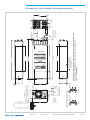
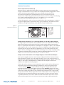
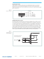
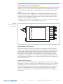
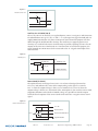
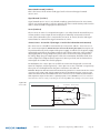
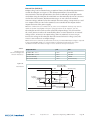
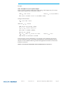
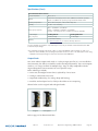
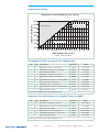
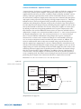
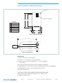
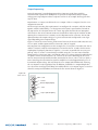
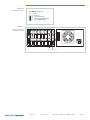
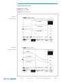
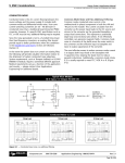
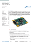
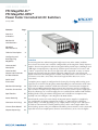
USER GUIDE | UG:119 PFC MegaPAC-ELTM PFC MegaPAC-HPELTM Power Factor Corrected AC-DC Switchers January 2009 ContentsPage Overview of Product 1 Mechanical3 Considerations MegaPAC3 Do’s and Don’ts Technical Description 4 Configuring and Reconfiguring MegaPACs 5 Overview ConverterPAC6 Description ConverterPAC10 Output and Connector Pin Identification Quick Install Instructions 11 Mechanical Drawings 14 Interface Connections 15 Specifications22 Power Derating 24 Connector Kit Listing 24 Current Share Boards 25 Output Sequencing 28 The PFC MegaPAC-EL and PFC MegaPAC-High Power Low Noise (HPEL) combine power factor correction (PFC) with the configurability of the MegaPAC family of power supplies. The PFC MegaPAC-EL and PFC MegaPAC-HPEL provide up to 1,600 Watts and 2,400 Watts of output powers respectively and have power densities of 4.3 W/in3 and 6.5 W/in3 respectively. The chassis has eight slots and can provide as many as sixteen outputs. The PFC MegaPAC-EL and PFC MegaPAC-HPEL have the same input and output connections, mounting points, and the same dimensions: 3.4”H x 6.0”W x 15.6”L (85,6 mm x 152,4 mm x 396,2 mm). Note that length of older units were 15.5” L (393,6 mm). A complete power supply is configured at the factory by selecting and inserting up to eight (four to six for the PFC MegaPAC-HPEL depending on ConverterPACs used) same length slide-in output assemblies called ConverterPACs. ConverterPACs incorporate one or two VI-200/VI-J00 and/or Maxi Vicor DC-DC converters and are available in a wide selection of output voltage and power levels. The net result is a power supply that offers the advantages of a custom supply, but is assembled from standard and modular building blocks. Using the VSPOC configurator tool available on vicorpower.com, anybody can now configure a PFC MegaPAC-EL/HPEL online. Manufactured at Vicor, the entire family of MegaPAC power supplies is completely user-configurable. If output requirements change, i.e., more power or a different output voltage is needed, upgrading is easy: simply unlock a single screw and replace the slide-in ConverterPAC assembly with one that is of the same length and has the desired voltage power rating. For additional flexibility, ConverterPACs can be connected in parallel to increase output power (booster ConverterPACs), or in series for higher UG:119 vicorpower.com Applications Engineering: 800 927.9474 Page 1 voltages (total output voltage should not exceed 400 V). The driver is to the left of the boosters when looking at the output end of the supply. A user-friendly interface provides control and output sequencing capability (see Page 16 for more information about this capability), in addition to useful status indicators. Please consult our Applications Engineering Department if you have other special requirements. Standard Features n Power Factor Correction; 0.99 at 115 Vac, 0.95 at 230 Vac n Universal Input: 85 - 264 Vac, 47-500 Hz, or 100 - 380 Vdc nPower Outputs: PFC MegaPAC-EL: 1,600 W at 230 Vac PFC MegaPAC-HPEL: 2,400 W at 230 Vac 1,200 W at 115 Vac 1,200 W at 115 Vac nOutputs: PFC MegaPAC-EL and HPEL: Up to 16 outputs n Output ripple: 10 mVp-p or 0.15% whichever is greater n Fan Cooled n Full power to 40°C; half power to 60°C n Soft start for limiting inrush current n Conducted EMI meets FCC Class A and EN55022 A specifications (some configurations meet Class B. contact factory) n Harmonic Distortion to EN61000-3-2 n RoHS compliant available n Output Sequencing and General Shutdown (General Shutdown refer to Page 17. Output sequencing refer to Page 28. Consult Applications Engineering for automatic sequencing circuitry.) n Overcurrent protection on all outputs n Overvoltage protection on all ConverterPAC outputs (not applicable with VI-J00 modules) n Overtemperature limiting on all ConverterPAC outputs (not applicable with VI-J00 modules) n Size: 3.4”H x 6.0”W x 15.6”L (85,6 mm x 152,4 mm x 396,2 mm) n Safety Agency Approvals: CE Mark, cTÜVus, UL Optional Features n DC OK status signal n Current Share Boards - see Pages 25 -28 n Output voltage adjustment range with built-in potentiometer UG:119 vicorpower.com Applications Engineering: 800 927.9474 Page 2 Mechanical Considerations The PFC MegaPAC-EL and PFC MegaPAC-HPEL can be mounted on any of four surfaces using standard 8-32 or 4 mm screws. The chassis comes with four mounting points on each surface; maximum allowable torque is 20 lb-in. The maximum penetration is 0.15 in. (3.8 mm). When selecting a mounting location and orientation, the unit should be positioned so air flow is not restricted. Maintain a 2" minimum clearance at both ends of the PFC MegaPAC-EL and PFC MegaPAC-HPEL and route all cables so airflow is not obstructed. The standard unit draws air in at the fan side/AC input side and exhausts air out the load side. If airflow ducting is used, use caution, as sharp turns could present back pressure to the PFC MegaPAC-EL and PFC MegaPAC-HPEL. The fan moves approximately 30 CFM of air. Avoid excessive bending of output power cables after they are connected to the PFC MegaPAC-EL and PFC MegaPAC-HPEL. For high-current outputs, use cable ties to support heavy cables in order to minimize mechanical stress on output studs. Be careful not to short-out to neighboring output studs. The PFC MegaPAC-EL and PFC MegaPAC-HPEL units are supplied with serrated, flanged hex-nuts on all output studs. Therefore, thread locking compounds or lock washers are not required. The maximum torque recommended on flanged nuts is 45 lb-in. Never loosen the inner nut on a ConverterPAC. This nut supports the hardware inside the ConverterPAC and is factory torqued. Avoid applications in which the unit is exposed to excessive shock or vibration levels. In such applications, a shock absorption mounting design is required. MegaPAC Do’s and Don’ts n For units without Autosense, do not leave ConverterPAC Sense lines open. Always terminate them to their respective output locally or at the load. Use twisted pair 22-24 AWG wire. If ConverterPAC has Autosense, no local sense connection is required. See Pages 11 and 12 for more information on Autosense. n If needed, use Connector Kit # 19-130040 for the PFC MegaPAC-EL and PFC MegaPAC-HPEL. n Always fill all output slots of the MegaPAC. If a slot is not filled with a ConverterPAC, it should be filled with an airblock. Airblocks are plastic assemblies whose main function is to fill up an empty slot. Any airflow escape from an empty slot significantly degrades thermal performance, and can result in overheating and damage to the power supply. n Always turn the power supply off, before disconnecting input or output wires. n NEVER disconnect the +Out and -Out load wires while the supply is operating as disconnecting WILL cause damage to the power supply. n Do not unplug ConverterPACs while input power is applied. They are not designed for hot-plug applications. n Do not restrict airflow to the unit. The cooling fan draws air into the unit and forces it out at the output power terminals. UG:119 vicorpower.com Applications Engineering: 800 927.9474 Page 3 n For power expansion, use booster ConverterPACs. Viewing the unit from the output terminal side, always insert boosters to the right side of the driver. n Do not use boosters as independent outputs. Disconnecting bus bars will damage booster ConverterPACs. n For booster arrays, do not remove busbars. n Always ensure that output hex-nuts are properly torqued before applying power to supply. n Run the output (+/–) power cables next to each other to minimize inductance. n Wait five minutes after shutting off power before inserting or removing ConverterPACs. n The MegaPACs does not have user serviceable components. They must be returned to the factory for repairs. Contact Customer Service for a RMA number before returning the unit. Do not attempt to repair or modify the power supply in any manner other than the exchange of ConverterPACs as described in this Design Guide. n Insert proper fault protection at power supply input terminals (i.e., a fuse). n Use proper size wires to avoid overheating and excessive voltage drop. n Never loosen the inner nut on a ConverterPAC. n Verify output nuts are tight before powering up. n FinQPACs require two slots each because of the larger heat sink attached to dissipate the extra heat generated by the higher power Maxi module. Refer to Page 8 for more information on which ConverterPACs can be used. Technical Description The PFC MegaPAC-EL and PFC MegaPAC-HPEL chassis consists of an offline single phase, power factor corrected front end, EMI filter, cooling fan, low noise filters, customer interface and associated housekeeping circuits. Input AC mains voltage (L1, L2 and GND) is applied to a terminal block. The input current is passed through an EMI filter designed to meet conducted noise limit A specifications of FCC Part 15, VDE 0871, and EN55022 Class A. At start up, inrush current is limited by a PTC thermistor. The PTC is shunted out shortly after initial power up by a DC bus voltage Sense circuit driving a relay. After rectification, the input voltage is put through a boost converter that keeps the AC input current sinusoidal and synchronized with the AC input voltage (in compliance with EN61000). The boost converter delivers regulated high voltage DC to the hold-up capacitors and backplane. The backplane supplies power to a variety of ConverterPAC assemblies that provide the desired regulated outputs. Voltage conversion in the output assemblies is achieved by Vicor’s family of ZeroCurrent Switching (ZCS) DC-DC converters. These are forward converters in which the main switching element switches at zero current. This patented topology has a number of unique attributes: low switching losses; high frequency operation resulting in reduced size for magnetics and capacitors; excellent line and load regulation; wide adjustment range for output; low EMI/RFI emissions and high efficiencies. At initial power up, the PFC MegaPAC-EL and PFC MegaPAC-HPEL outputs are disabled to limit the inrush current and to allow the DC bus potential to settle out to the correct operating level. A low-power flyback converter operating with PWM current-mode control converts the high voltage DC bus into regulated low voltage to power the internal housekeeping circuits and DC cooling fan. The internal housekeeping Vcc UG:119 vicorpower.com Applications Engineering: 800 927.9474 Page 4 comes up within two seconds after the application of input power. Once the high voltage bus is within its limits, the AC OK signal asserts to a TTL “1” indicating the input power is OK, and enables the power outputs. An auxiliary Vcc output of 5 Vdc sourcing up to 0.3 A is provided for peripheral use. An output Enable/Disable function is provided by using an optocoupler to control the Gate In pins of the ConverterPAC assemblies. If the Enable/Disable control pin is pulled low, the optocoupler turns on, pulling the Gate In pin low and disabling the ConverterPAC output. The nominal delay for an output to come up when measured from release of the Enable/Disable pin is 10-15 ms. The General Shutdown function controls all outputs simultaneously and works in a similar manner. The ride-through (hold-up) time is the amount of time the load can be supported before loss of output regulation after the loss of input power. Detecting the loss of input power takes a finite time period after which the AC Power OK signal goes from a TTL “1” to “0." This signal is available for use within 1.2 seconds after initial power up and can be used to indicate an impending loss of power. At least 3 ms of warning time is given. Following the loss of input power, the outputs are disabled when the bus voltage drops below its operating threshold. Figure 1. Input PFC MegaPAC-EL and PFC MegaPAC-HPEL Low Noise Architecture Line Filter Soft Start Circuit Rectifier Boost Converter High Voltage DC Bus Waveform Sample Current Sample QPAC #1 Power Output QPAC #2 Power Output QPAC #3 Power Output QPAC #8 Power Output PFC Control Customer Interface E/D Control Fan Current Monitor Enable/Disable Control Housekeeping Power Configuring and Reconfiguring MegaPACs Most ConverterPACs of the same length can be inserted into any available slot of a MegaPAC chassis. They can also be easily added, replaced, or moved by sliding the assemblies in or out of a MegaPAC chassis. For outputs greater than 200 Watts, a driver QPAC and one or more booster ConverterPACs will be used. For outputs greater than 600 Watts, a driver FinQPAC and one or more booster ConverterPACs will be used. Arrays of drivers and boosters should be configured so all boosters are placed in the slots to the immediate right of the driver when looking at the output end of the MegaPAC. Prior to removing or installing ConverterPACs, you must remove power from the MegaPAC and wait five minutes. Failure to do so can result in personal injury or damage to the supply. Take standard ESD precautions when handling ConverterPACs. Removing ConverterPACs ConverterPACs can be removed by loosening the captive screw at the base. Once this screw has been loosened, the ConverterPAC will slide out of the chassis. Once a ConverterPAC has been removed, the empty slot MUST be filled with either another ConverterPAC or an airblock. If the slot is left empty, it will provide an airflow escape and cause failure to the power supply. UG:119 vicorpower.com Applications Engineering: 800 927.9474 Page 5 Installing ConverterPACs as Drivers ConverterPACs can be installed in empty slots by simply sliding in the new ConverterPAC and securing the screw at the base. Power and interface connections can be made after the ConverterPAC has been installed. Installing Booster ConverterPACs to Increase Output Power ConverterPACs can be paralleled for more power. Additional power to an output is obtained by connecting one or more boosters in parallel with a single driver. The driver can be placed in any open slot. All boosters should be inserted in the slots to the immediate right of the driver as viewed from the output end of the MegaPAC. Figure 2 shows a driver placed in slots #1 and 3, boosters placed in slots # 2 through 4. After inserting the driver and boosters, they are paralleled using bus bars across the positive and negative output studs. Drivers should not be paralleled with each other. Bus bars between a driver and booster(s) should never be disconnected. For help in identifying boosters and drivers, refer to the Part Numbering section on Page 8. Please note that total output voltage should not exceed the converter baseplate-output isolation rating of 400 V. For detailed guidelines on how outputs should be placed in series, please refer to the Applications Note (Creating High Voltage Outputs) available on the website at www.vicorpower.com. Figure 2. Paralleling ConverterPACs Bus Bars for Paralleling Loosen screw to remove ConverterPAC 1 2 3 4 5 6 7 8 Driver Boosters ConverterPAC Functional Description ConverterPACs are the family of slide-in output assemblies used in MegaPAC power supplies. Most ConverterPACs of the same length are interchangeable within a MegaPAC or between different AC input MegaPAC chassis. They can be added, moved, or changed as necessary. A key feature of the Extended Length ConverterPAC is the low ripple and noise output to 10 mV p-p or 0.15%, whichever is greater. The following Extended Length ConverterPACs can be used in the PFC MegaPAC/EL - Low Noise. + _ VI-200 QPAC QPAC (L) The QPAC output assembly consists of a VI-200 DC-DC converter that converts the unregulated high voltage bus to the desired regulated output voltage. Each QPAC (L) can provide up to 200 Watts of output power, and booster QPACs can be added in parallel for more power. Power and slave QPACs can be added in parallel for more power. QPACs are fused with a PC-Tron, DC-rated, fast-acting fuse. An active preload ensures the DC-DC converter operates in its highest noise performance range. As the load on the UG:119 vicorpower.com Applications Engineering: 800 927.9474 Page 6 module increases, the preload removes itself from the circuit. QPACs, using the VI-200 module, have an optional DC OK TTL signal. All QPACs have overcurrent protection with automatic recovery when the overcurrent condition is removed. Overvoltage Protection (OVP) and Overtemperature Limiting (OTL) are available. Please note that for the QPAC (L) the output voltage from either output terminal to chassis should not exceed 400 Vdc, or peak. M1 VI-J00 M2 VI-J00 M2 M1 DualPAC JuniorQPAC (LJ) The JuniorQPAC output assembly consists of a VI-J00 Vicor DC-DC converter that converts the unregulated high voltage bus to the desired regulated output voltage. OVP and OTL is not available. Please note that for the QPAC (L) the output voltage from either output terminal to chassis should not exceed 400 Vdc, or peak. VI-J00 JuniorQPAC + _ Maxi FinQPAC DualQPAC (LD) The DualQPAC output assembly consists of two VI-J00 DC-DC converters that provide two isolated output voltages. DualQPACs can provide up to 100 Watts of output power from each output. The DualQPACs are fused with a PC-Tron, DC-rated, fast-acting fuse. An active preload ensures the DC-DC converter operates in its highest noise performance range. OVP and OTL is not available. Please note that for the QPAC (L) the output voltage from either output terminal to chassis should not exceed 400 Vdc, or peak. For detailed pin out description, refer to Page 10. FinQPAC (PZL) The FinQPAC output assembly consists of a Maxi DC-DC converter that converts the unregulated high voltage bus to the desired regulated output voltage. Each Maxi module can provide up to 600 Watts of output power. Each FinQPAC occupies two slots because it has an extra large heat sink attached to dissipate the heat generated by this more powerful Maxi converter. It cannot be used in any other member of the MegaPAC Family. FinQPACs have overcurrent protection with automatic recovery when the overcurrent condition is removed. Overvoltage Protection (OVP) and Overtemperature Limiting (OTL) are available. Please note that for the FinQPAC (PZL) the output voltage from either output terminal to chassis should not exceed 400 Vdc, or peak. UG:119 vicorpower.com Applications Engineering: 800 927.9474 Page 7 List of ConverterPACs used in the PFC MegaPAC-EL and PFC MegaPAC-HPEL Low Noise and their features ConverterPAC OVP OCP OTL RS/AS* LS/AS* PG TrimPot QPAC (L) Std Std Std AS* AS* Opt Opt DualQPAC (LD) N/A Std N/A AS* AS* Opt N/A JuniorQPAC(LJ) N/A Std N/A AS* AS* Opt Opt FinQPAC(PZL)+ Std Std Std AS* AS* Opt Opt OVP Overvoltage Protection (latching) RS Remote Sense OCP Overcurrent Protection (auto-recovery) LS Local Sense OTL Overtemperature Limiting ASAutosense PG Power Good (DC OK TTL Signal) + Maxi OTL is non-latching *See Pages 11 and 12 for more information on Autosense. Note: All ConverterPACs mentioned above can be paralleled EXCEPT the DualQPAC and JuniorQPAC. Part Numbering PFC MegaPAC-EL MPxA-7xBxxxx-xC-xD ex. MP5-782560-G-EL PFC MegaPAC-HPEL MXxA-7xBxxxx-xC-xD ex. MX4-742543-2-EL MP = MegaPAC prefix xA = number of outputs 7 = power factor corrected xC = optional code ex. G = RoHS MX = PFC MegaPAC-HPEL prefix X = PFC chassis that can use Maxi xB = Number of modules xxxx = assigned by Vicor xD = optional code e.g. EL = Extended Length UG:119 vicorpower.com Applications Engineering: 800 927.9474 Page 8 ConverterPACXxDV/xEAxF ex. L15V/10A X = ConverterPAC type (For RoHS, add G to current prefix) xD = voltage out xE = current out (rounded to 1 decimal point) xF = Can be multiple options* (see Page 9) Part Numbering (Cont.) * ConverterPAC options B Booster module M Military Grade module D DC OK or Power Good1 R RAM external3 F Full 50-110% output adjustment2 S Trimpot removed for external F1 50-107.5% output adjustment F2 50-105% output adjustment F3 BatPAC adjustment T 90-110% output adjustment4 50-102.5% output adjustment T1 90-107.5% output adjustment F4 50-100% output adjustment T2 90-105% output adjustment F5 60-110% output adjustment T3 90-102.5% output adjustment F6 70-110% output adjustment T4 90-100% output adjustment F7 80-110% output adjustment T5 98-105% output adjustment F8 90-110% output adjustment T6 100-110% output adjustment F9 100-110% output adjustment V1 "VXI" low noise (150 mV) 15 V < VOUT I Industrial Grade module K Custom SRF module used P Preload ≤ 24 V outputs4 V2 "VXI" low noise (50 mV) VOUT ≤ 15 Vdc V3 “VXI” low noise (1% ripple) VOUT > 24 V [1] D option: Optional for all ConverterPACs used in this power supply [2] T & F options: Optional for all ConverterPACs used in this power supply EXCEPT the DualQPAC [3] R option: N/A to any ConverterPACs used in the PFC MegaPAC-EL/PFC MegaPAC-HPEL [4] V options: N/A to any ConverterPACs used in the PFC MegaPAC-EL/PFC MegaPAC-HPEL UG:119 vicorpower.com Applications Engineering: 800 927.9474 Page 9 QPAC VI-200 MODULE ConverterPAC Output and Connector Pin Identification QPAC JuniorQPAC J2 REMOTE SENSE TRIM/SC & POWER GOOD + V0UT MATING HDWR: HOUSING- MOLEX P/N: 39-01-0073 TERMINALS- MOLEX P/N: 39-00-0031 CRIMP TOOL MOLEX P/N: 57005-5000 OUTPUT ADJUST - VOUT DUAL QPAC 7 6 5 4 3 2 1 J2-PIN1 DualQPAC J1-B-PIN1(M1) J2-PIN1 7 6 5 TRIM TOP TRIM BOT N/C J1-B +SENSE -SENSE TRIM Vcc IN POWER GOOD POWER GOOD INVERTED SIGNAL GROUND (OUTPUT CONNECTORS) 1 AND 4 +V OUT 4 5 1 2 2 AND 5 -V OUT 6 3 3 +R/SENSE 6 -R/SENSE 4 Vcc IN 3 POWER GOOD 2 POWER GOOD INVERTED J1-A 1 SIGNAL GROUND (OUTPUT CONNECTORS) MATING HDWR: HOUSING- MOLEX P/N: 39-01-2060 TERMINALS- MOLEX P/N: 39-00-0039 CRIMP TOOL MOLEX P/N: 11-01-0197 MATING HDWR: 4 5 1 2 1 AND 4 +V OUT HOUSING- MOLEX P/N: 39-01-2060 2 AND 5 -V OUT 6 3 3 +R/SENSE 6 -R/SENSE TERMINALS- MOLEX P/N: 39-00-0039 CRIMP TOOL MOLEX P/N: 11-01-0197 J1-A-PIN1 (M2) DUALQPAC - COMPONENT SIDE VIEW M2 M1 Output A 48V/2.1A (J1-B) J1-B (M1) (J1-A) J1-A (M2) Output B 12V/8.3A Example: LD12V/8.3A-48V/2.1A FINQPAC FinQPAC + 0UT OUTPUT ADJUST - OUT P2 REMOTE SENSE TRIM/SC & POWER GOOD 7 6 5 4 3 2 1 +SENSE -SENSE TRIM Vcc IN POWER GOOD POWER GOOD INVERTED SIGNAL GROUND MATING HDWR: HOUSING- MOLEX P/N: 39-01-0073 P2-PIN1 TERMINALS- MOLEX P/N: 39-00-0031 CRIMP TOOL MOLEX P/N: 57005-5000 Note: 1. All ConverterPACs except the FinQPAC occupy one slot. The FinQPAC occupies two slots. 2. New output studs have been installed on the ConverterPACs and are 1/8th inch longer. Refer to Pages 14 and 23 for more information. UG:119 vicorpower.com Applications Engineering: 800 927.9474 Page 10 PFC MegaPAC-EL and -HPEL “Quick Install” Instructions (For Mechanical Drawing, see Page 14) Mounting the PFC MegaPAC-EL and PFC MegaPAC-HPEL n Mount the power supply on any of its four sides. n Use #8-32 or 4 mm mounting screws. Do not exceed a maximum penetration of 0.15" (3,8 mm). The maximum allowable torque is 20 lb-in. n Maintain 2" (5,1 cm) clearance at either end for airflow. Input Connections L1 Input Power J9 L2 DO NOT OPERATE WITHOUT EARTH GROUND INPUTS 115/230 VAC 47 TO 500 Hz 300VDC NOTE: SET SCREW MAXIMUM TORQUE = 4.4 INCH POUNDS n Apply input AC power to terminal block J9 using a pressure screw terminal. n Strip length of AC power conductors to be 0.35 inches. n Maximum torque is 4.4 lb-in. n Place a fuse or circuit breaker in the input line for safety reasons. LABEL NO: 94-00046 REV B INPUT CONNECTIONS J9-1 EARTH GROUND J9-2 L2-NEUTRAL J9-3 L1 Input Panel Connectors n Use a maximum wire size of 14 AWG with soldered terminals. n The connector manufacturer recommends the wires not be tinned. A ferrule (Phoenix P/N 32-00-58-0, purchased from other sources) can be used to prevent fraying. Output Connections QPAC (L) Power Connections Installing ring lugs and/or bus bars on output studs: + V0UT OUTPUT ADJUST n The upper stud is Positive and the lower stud is the Return. n Newer outputs studs are 1/8th inch longer. - VOUT See Pages 14 and 23 for more information. J2-PIN1 n Remove nut. Single Output QPAC J1A (M2) 6 5 J1B (M1) 5 4 4 6 + + 1 -RS +RS - + -RS +RS - 3 1 3 2 2 + DualQPAC Output Connector n Place ring lug over output stud. n Replace and tighten outer nut to a maximum torque of 45 lb-in. Do Not Over-Tighten Nuts. n Verify all output nuts are properly installed before turning on supply. Installing power connectors on DualQPACs - J1A (M2) and J1B (M1): n Use Molex mating receptacle #39-01-2060 with #39-00-0039 terminals provided. n Pins 1 and 4 are Positive, while pins 2 and 5 are the Return. n Attach terminals to 18-24 AWG stranded wire using Molex tool #11-01-0197. Sense Connections Newer power supplies have the Autosense feature. For these units, if Remote Sense connections are not made or needed, no Local Sense selection is necessary - simply connect the output to the load and the unit will automatically operate in Local Sense. If Remote Sense connections are made, the unit will operate in a Remote Sense mode. Remote Sense terminals should be terminated to their respective output i.e. - RS to Output and + RS to + Output. See Page 12 for more information on Autosense. For units without Autosense, sense connections must ALWAYS be made. Not connecting sense lines to their respective output can cause failure to the unit. WARNING: NEVER disconnect the +Out and -Out load wires while the supply is operating as disconnecting WILL cause damage to the power supply. UG:119 vicorpower.com Applications Engineering: 800 927.9474 Page 11 Sense Connector J2 (and P2 for the FinQPAC): J2-PIN1 7 6 5 TRIM TOP 4 3 2 1 Vcc IN POWER GOOD TRIM BOT N/C POWER GOOD INVERTED SIGNAL GROUND J2/P2 Sense Connectors n Sense connections do not have to be made if either the Local Sense option was ordered (older units) or if Autosense is present (see previous note on Autosense.) n Attach opposite ends of Sense lines to point where regulation is desired. n Verify that Sense lines are not cross-connected before applying input power. n For the QPAC, J2-7 is the +Sense and J2-6 is the -Sense. n For the FinQPAC, P2-7 is the + Sense and P2-6 is the -Sense. n Use Molex mating receptacle #39-01-0073 with #39-00-0031 terminals provided n Attach terminals to 22-28 AWG stranded wire using Molex tool #57005-5000. (OUTPUT CONNECTORS) Sense Connections on DualQPACs: n Sense connections do not have to be made either if the Local Sense option has J1-B (M1) 1 AND 4 +V OUT 4 5 1 2 2 AND 5 -V OUT 6 3 3 +R/SENSE 6 -R/SENSE been ordered or Autosense is present (refer to note on Autosense). n Sense connections are available on the J2 connector (P2 for the FinQPAC) or the J1A (M2) and J1B (M1) connectors. n If using J2 or P2 connector, see instructions on Page 12. J1-A (M2) 1 AND 4 +V OUT 4 5 1 2 2 AND 5 -V OUT n On J1A and J1B, Pin 3 is the +Sense and Pin 6 is the -Sense. 6 3 3 +R/SENSE 6 -R/SENSE n Use Molex mating receptacle #39-01-2060 with #39-00-0039 terminals provided. DualQPAC Sense Connector n Attach terminals to 18-24 AWG twisted pair wire using Molex tool #11-01-0197. n Verify that Sense lines are not cross connected before applying input power. J2-PIN1 7 6 5 TRIM TOP 4 3 2 1 Vcc IN POWER GOOD TRIM BOT N/C Trim Pin Connection J2 for QPACs (and P2 for FinQPAC) n The Trim J2 connection should only be made if the Trim option has not been installed. (A “T” or an “F” in the ConverterPAC part number means the Trim option is installed; ex. M5V/40AT.) POWER GOOD INVERTED n For the QPAC, refer to J2 Connector. J2-5 provides Trim Access. SIGNAL GROUND n For the FinQPAC, refer to P2 Connector. P2-5 provides Trim Access. Trim Pin Connection on the J2 /P2 Connector Trim Pin Connector For DualQPAC J2-PIN1 7 6 5 TRIM TOP B 4 3 2 1 Vcc IN POWER GOOD TRIM BOT A N/C POWER GOOD INVERTED n Use Molex mating receptacle #39-01-0073 with #39-00-0031 terminals provided. n Attach terminals to 22-28 AWG stranded wire using Molex tool #57005-5000. Trim Pin Connection J2 for DualQPACs n The Trim J2 connection should only be made if the Trim option has not been installed. n J2-7 is Trim B and J2-6 is Trim A. n Use Molex mating receptacle #39-01-0073 and #39-00-0031 terminals provided. n Attach terminals to 22-28 AWG twisted pair wire using Molex tool #57005-5000. SIGNAL GROUND UG:119 vicorpower.com Applications Engineering: 800 927.9474 Page 12 7 6 5 4 3 2 1 +SENSE DC OK (Power Good) Connection J2 (and P2 for FinQPAC) -SENSE n DC OK is only available as an option and is not present unless requested. TRIM Vcc IN POWER GOOD POWER GOOD INVERTED SIGNAL GROUND DC OK/Power Good Connection on the J2 /P2 Connector 5 6 2 3 4 7 8 9 10 11 12 J10 INTERFACE E/D-1 E/D-2 E/D-3 E/D-4 E/D-5 E/D-6 n For the FinQPAC, refer to the P2 connector. P2-3 is Power Good. n Use Molex mating receptacle #39-01-0073 with #39-00-0031 terminals provided. n Attach terminals to 22-28 AWG stranded wire using Molex tool #57005-5000. Interface Connections J10 J10 1 J10-1 J10-2 J10-3 J10-4 J10-5 J10-6 n For the QPAC, refer to the J2 connector. J2-3 is Power Good. J10-7 J10-8 J10-9 J10-10 J10-11 J10-12 E/D-7 E/D-8 Vcc +5V, 0.3A SIGNAL GROUND AC POWER OK GEN SHUTDOWN n Use Molex mating receptacle #39-01-2120 with #39-00-0039 terminals. n J10-1 through 8 are Enable/Disable for slots 1 through 8. n J10-9 is Vcc, J10-10 is Signal Ground, J10-11 is AC Power OK, and J10-12 is General Shutdown. n Attach terminals to 18-24 AWG stranded wire using Molex tool #11-01-0122. Interface Connections J10 UG:119 vicorpower.com Applications Engineering: 800 927.9474 Page 13 UG:119 47 TO 500 Hz LABEL NO: 94-00046 REV B vicorpower.com 47 TO 500 Hz L2 Applications Engineering: 800 927.9474 ORIGINAL FLANGED NUT RE-DESIGNED OUTPUT PANEL AND STUDS LABEL NO: 94-00046 REV B .25 [6.35] BRASS INSERT 2.75 [69.85] (T0P AND BOTH SIDES) CUSTOMER MOUNTING HOLES (16X) M4 OR #8-32 THREAD MAXIMUM SCREW PENETRATION .150 [4.00 MM] FROM OUTSIDE SURFACE. 10.01 [254.25] (ORIGINAL LENGTH) 15.50 [393.63] 10.01 [254.25] (RE-DESIGNED LENGTH) 15.62 [396.81] 10.01 [254.25] 1.40 [35.56] .73 [18.52] 1.46 [37.03] 1/4 - 20 SERRATED FLANGED NUT ZINC PLATED STEEL WITH OPTIONAL BUSS BARS .41 [10.35] ORIGINAL STUD AND PANEL .53 [13.39] RE-DESIGNED STUD AND PANEL NOTE: EITHER THE ORIGINAL OR RE-DESIGNED OUTPUT STUD AND PANEL COMBINATION MAY BE PRESENT. THE NEW OUTPUT PANEL HAS A BRASS INSERT AND THE STUD IS 1/8 INCH LONGER. 2.92 [74.17] .470 [11.94] 5.100 [129.54] .21 [5.33] DO NOT OPERATE WITHOUT EARTH GROUND FAN (DIRECTION OF AIR FLOW OPTIONAL) NOTE: SET SCREW MAXIMUM TORQUE = 4.4 INCH POUNDS 300VDC L2 DO NOT OPERATE WITHOUT EARTH GROUND INPUTS 115/230 VAC NOTE: SET SCREW MAXIMUM TORQUE = 4.4 INCH POUNDS J9-1 EARTH GROUND J9-2 L2-NEUTRAL J9-3 L1 300VDC INPUT CONNECTIONS L1 INPUTS 115/230 VAC 14 AWG WIRE 3.37 [85.60] 2.92 [74.17] .21 [5.33] MATING HDWR: HOUSING-MOLEX P/N: 39-01-2120. TERMINALS-MOLEX P/N: 39-00-0039 CRIMP TOOL-MOLEX P/N: 11-01-0122 L1 CLAMPING SCREWS 6.04 [153.42] 9 10 11 12 6 8 5 7 4 3 2 1 J10 E/D-1 E/D-2 E/D-3 E/D-4 E/D-5 E/D-6 E/D-7 E/D-8 Vcc +5V, 0.3A SIGNAL GROUND AC POWER OK GEN SHUTDOWN J10 INTERFACE J10-1 J10-2 J10-3 J10-4 J10-5 J10-6 J10-7 J10-8 J10-9 J10-1O J10-11 J10-12 15.18 [385.69] 2.77 [70.23] 3.28 [83.19] .47 [11.94] 5.10 (129.5 MM) 7 SP. @ .7285 (18.5 MM) PFC MegaPAC-EL and PFC MegaPAC-HPEL Mechanical Drawing Page 14 Interface Connections Chassis Input Power Terminals (J9) Input AC power is applied to terminal block J9 using a pressure screw terminal that accepts a maximum wire size of 14 AWG. The insulation should be stripped 0 .35 inches and the maximum torque applied to the screws should not exceed 4.4 lb-in. The connector manufacturer recommends the wires not be tinned. A ferrule (Phoenix P/N 32-00-58-0, purchased from other sources) can be used to prevent fraying. J9-1 (GND) is Earth Ground for safety; J9-2 (L2) and J9-3 (L1) are the other Hot connections. For Input DC power, L2 is (+) and L1 is (-). A fault clearing device, such as a fuse or circuit breaker with a maximum 15 A rating at the power supply input is required for safety agency compliance. It should be sized to handle the start-up inrush current of 25 A pk at 115 Vrms and 230 Vrms. Figure 3. Input Panel Connectors L1 L1 L2 INPUTS 115/230 VAC 47 TO 500 Hz 300VDC DO NOT OPERATE WITHOUT EARTH GROUND NOTE: SET SCREW MAXIMUM TORQUE = 4.4 INCH POUNDS LABEL NO: 94-00046 REV B J10 INPUTS 115/230 VAC 47 TO 500 Hz 300VDC L2 DO NOT OPERATE WITHOUT EARTH GROUND NOTE: SET SCREW MAXIMUM TORQUE = 4.4 INCH POUNDS LABEL NO: 94-00046 REV B INPUT CONNECTIONS J9-1 EARTH GROUND J9-2 L2-NEUTRAL J9-3 L1 Output Power Connections (+P, -P for Single Output, or J1A/J1B for Dual Outputs) For single output ConverterPACs, these terminals are two 1/4-20 plated steel studs. The upper stud is positive with respect to the lower stud. For dual output ConverterPACs, there is a 6-pin Molex connector for each output. J1A (M2) pins 1 and 4 are the +Output, and J1A pins 2 and 5 are the -Output. Pins 3 and 6 are duplicates of the Remote Sense terminals present on J2A and J2B. Use appropriate wire size rated to handle the full output current, including short circuit levels. Avoid large current loops in output cables; run power and return cables next to one another to minimize inductive effects. All outputs are isolated and can provide positive or negative outputs. Output +/-Sense Connections -J2 for Single Output, or J1A/J1B for Dual Outputs Newer power supplies may have some outputs configured with the Autosense feature that automatically locally senses the output if remote sense is not used. To check if an output has the Autosense feature, measure the impedance from the + Out to + Sense and - Out to - Sense pins. If the impedance is 5 Ohms, then the output has Autosense and does not require local sense jumpers. If units do not have Autosense, sense connections must be made. When making sense connections, keep in mind that although all outputs are open-Sense protected, the +/-Sense terminals MUST be connected to their respective outputs before the PFC MegaPAC-EL and PFC MegaPAC-HPEL are powered up. (NEVER disconnect the +Out and -Out load wires while the supply is operating as disconnecting WILL cause damage to the power supply.) Regardless of the output polarity configured, the +Sense should always connect to the +Power output. The -Sense connects to the -Power output. Sense connections are not required on booster ConverterPACs or if the Local Sense option is specified (old units). Local Sense mode means that the Remote Sense lines are not connected. Sense pins can be accessed on J1A/J1B or J2A/J2B on dual output units. UG:119 vicorpower.com Applications Engineering: 800 927.9474 Page 15 Signal Ground (J10-10) Signal Ground (see Figure 4 and Connector Pin Identification below) is an isolated ground reference for all J10 interfacing signals, and can be used for ConverterPAC output status signals such as Power Good. This is not the same as Earth Ground on input power connector J9. Figure 4. Interface Connector J10 INTERFACE J10 5 6 1 2 3 4 7 8 9 10 11 12 J10-1 J10-2 J10-3 J10-4 J10-5 J10-6 E/D-1 E/D-2 E/D-3 E/D-4 E/D-5 E/D-6 J10-7 J10-8 J10-9 J10-10 J10-11 J10-12 E/D-7 E/D-8 Vcc +5V, 0.3A SIGNAL GROUND AC POWER OK GEN SHUTDOWN Enable/Disable (J10-1 to J10-8) The Enable/Disable control pins allow ConverterPAC outputs to be set either on or off. J10-1 through J10-8 are the control pins for output positions 1 through 8, respectively (see Figure 5 and Connector Pin Identification above). For DualQPACs, both outputs are set on or off by the same control pin. In parallel arrays, only the driver ConverterPAC need be controlled. The Enable/Disable pins must be pulled low to less than 0.7 V with respect to Signal Ground to disable the outputs. They will sink 10 mA maximum. These pins should be open circuited or allowed to exceed 4.5 V when enabled. Do not apply more than 6 V to these inputs at any time. If driven from an electromechanical switch or relay, a capacitor should be connected to eliminate the effects of switch bounce. Figure 5. Enable/Disable and General Shutdown J10 9 Using external transistors to drive enable/diable logic Enable/Disable Output 1 TTL "1" (OFF) TTL "0" (ON) 1 0 General Shutdown Signal Ground UG:119 vicorpower.com PFC MegaPAC-EL Vcc 1 12 10 Applications Engineering: 800 927.9474 Page 16 Enable/Disable control of Maxi Module Arrays When using the Enable/Disable function on an output that consists of two or more Maxi modules, it is necessary to connect the E/D pins of the corresponding module locations together such that both modules are commanded to turn ON or OFF simultaneously. Example: Slots 2, 4 and 6 have been configured as a single output parallel array (see Fig. 6) In order to disable the 48V output, E/D 2, E/D 4 and E/D 6 should be shorted together as shown in Fig. 6. With E/Ds connected together, a single switch can then be used to remotely enable and disable the output. **Note: For single output power supply configurations, the simplest method of remotely enabling and disabling the output is to use the General Shutdown (GSD) function. Figure 6. Enable/Disable Control of Maxi Arrays J10 Slot# 8 L3.3V/40A 2 4 6 Slot# 7 L5V/40A MegaPAC Power Factor Corrected J1 123 Slot# 6 PZL48V/12.5AJS1 10 Slot# 5 Slot# 4 PZL48V/12.5AJS1 Slot# 3 Slot# 2 PZL48V/12.5AN Slot# 1 General Shutdown /GSD (J10-12) The GSD control pin on J10-12 allows simultaneous shutdown of all ConverterPAC outputs (see Connector Pin Identification on Page 16). This pin must be pulled down to less than 0.7 V, and will sink 13 mA maximum to shut down all outputs. The GSD pin should be open circuited or allowed to exceed 4.5 V when not in use, or when the outputs are to be enabled. Do not apply more than 6 V to this input at any time. Normal open circuit voltage is 1.5 to 3 V with respect to Signal Ground. If driven from an electromechanical switch or relay, a capacitor should be connected to eliminate the effects of switch bounce. AC OK / Power Fail (J10-11) This is an active high TTL compatible signal and provides a status indication of the AC input power (see Figure 7 and Connector Pin Identification on Page 16). It is capable of sourcing 0.5 mA at > 3.2 V and sink 16 mA at < 0.5 V. This signal switches to a TTL “1” when the high voltage bus exceeds low-line condition during turn-on, and switches to a TTL “0” 3 ms (minimum) before loss of output regulation due to the loss of input AC power. This signal can be used to warn external control circuits of an impending loss of power. UG:119 vicorpower.com Applications Engineering: 800 927.9474 Page 17 Figure 7. J10 AC OK Power Fail +5V 10K 2.49K 11 AC Power OK PN2222 10 Signal Ground Auxiliary Vcc +5V/0.3A (J10-9) The Vcc on J10-9 is an auxiliary 5 V regulated power source (see Figure 8 and Connector Pin Identification on Page 16). It is +5 Vdc +/–5% with respect to Signal Ground and can supply 300 mA maximum. It is short-circuit-proof, but if shorted all outputs will shut down through the Enable/Disable circuitry. The Auxiliary Vcc typically powers user circuitry or is used with the Power Good circuitry to provide a pull-up reference for the outputs of the DC Power Good circuit on a ConverterPAC. If used for this purpose, the Signal Ground on J10-10 must also be connected to the J3-1 Signal Ground pin of the ConverterPAC. Figure 8. Auxiliary Vcc +5V/300 mA 78M05 J10 9 Auxiliary Vcc 0.1 µF 10 Signal Ground Power Good (J2-3/P2-3) The optional Power Good signal on J2-3/P2-3 is referenced to Signal Ground on J2-1/P2-1, and indicates the status of the output voltage. This signal is asserted a TTL “1” when the output voltage is above 95% of nominal. It is a TTL “0” when the output voltage is below 85% of nominal. If the Trim option is also used, the Power Good trip points DO NOT track with the trimmed voltage. It is possible to trim the output below the fixed setpoints of the Power Good circuit and cause a negative Power Good signal. Figure 9. Power Good and Vcc J2/P2 2.49K 2.49K 10K 2N2222 4 Vcc In 3 Power Good 2 1 UG:119 vicorpower.com Power Good Inverted Signal Ground Applications Engineering: 800 927.9474 Page 18 Power Good Inverted (J2-2/P2-2) This is the inverse of the Power Good signal and is referenced to Signal Ground on J2-1/P2-1. Signal Ground (J1-1/P2-1) Signal Ground on J2-1/P2-1 is an isolated secondary ground reference for J2/P2 status signals. It is used to provide a reference point for the Power Good circuitry and is not the same as Earth Ground on input power connector J9. Vcc In (J2-4/P2-4) The Vcc In on J2-4/P2-4 is an input that requires +5 V either from the J10 Auxiliary Vcc, or from another source. Input current to this pin is limited by an internal resistor to 3 mA. If the J10 Auxiliary Vcc is connected to Vcc In on J2-4/P2-4, then the J10 Signal Ground must be connected to Signal Ground on J2-1/P2-1. +Sense/–Sense - J2-6 and J2-7 (See Pages 11 and 12 for information on Autosense) The +Sense on J2-7 should be connected to the +Power Out, and the –Sense on J2-7 to the –Power Out terminal. Do not reverse or leave the Sense pins open. Sense pins can be terminated locally at the output of the power supply, in which case the power supply will provide regulation at the output terminals. The voltage appearing at the load may drop slightly due to voltage drop in the power cables. If it is necessary to compensate for voltage drop along the output power cables, this termination should be made close to the output load. Compensation of up to 0.5 V (0.25 V per lead) can be obtained. Use twisted pair 22-24 AWG wire for this purpose. For DualQPACs, the +Sense pins are available on connectors designated as J2A-2 and J2B-2 for outputs A and B, respectively. –Sense pins are on J1A-3 and J1B-3, respectively. These pins are also duplicated on the power connectors J1A and J1B. Reminder: Only units with Autosense will automatically operate in Local Sense mode if no Sense connections are made. It will operate in Remote Sense mode if Remote Sense connections are made. Units without Autosense MUST have sense connections (Local or Remote) terminated to their respective output for the unit to operate properly. Further, NEVER disconnect the +Out and -Out load wires while the supply is operating as disconnecting WILL cause damage to the power supply. Figure 10. Sense Leads (Local Sense) +P +Out (Remote Sense) P2-7 +Sense Load Use 22-24 AWG Twisted Pair Wires P2-6 -Sense -P -Out UG:119 vicorpower.com Applications Engineering: 800 927.9474 Page 19 External Trim (J2-5/P2-5) Output voltage can be trimmed using an optional factory-installed Trim potentiometer or with the Trim pin (see Figure 11). The Trim potentiometer is located on the ConverterPAC. If the Trim potentiometer has not been ordered, the Trim pin must be used. When using the Trim pin, the Trim limits are determined by the DC-DC converter used on the ConverterPAC. Maximum Trim ranges are 10% above the nominal converter voltage and 50% below the nominal converter voltage (except 10 V, 12 V and 15 V outputs which are 10% below nominal) as measured from the output studs or output connector of the power supply. Note: The combined effects of module trim up, remote sense and dynamic load step may cause the module to trip OVP. (Tripping OVP will require cycling input power to the supply off, then on). The Trim pin on J2/P2 can be used to control the output voltage. It is referenced to the -Sense pin on J2 and can be controlled by either a resistor network or an external voltage source. To increase an output voltage above its nominal, it is necessary to increase the voltage at the Trim pin above the internal reference voltage (Vref). The reverse is true to decrease an output voltage. Note: Converters are sometimes pretrimmed at the factory if a nonstandard output voltage is requested. If using a nonstandard voltage, or if a ConverterPAC is ordered with a Trim option, the resistor calculations will differ from those on Page 21. Please consult the factory for assistance. Table 1. Module Internal Reference Voltages and Thevenin Resistances. Output Module Vref RTH VI-200/VI-J00 ³3.3 V 2.50 V 10.0 kW VI-200/VI-J00 < 3.3 V 0.97 V 3.88 kW Maxi (Pre-Defined) 1.23 V 1.0 kW Maxi (User Defined) 1.23 V Consult Factory Figure 11. Use 22-24 AWG Twisted Pair Wires External Trim (Remote Sense) +P +Out R1 P2-7 +Sense To Error Amplifier + RTH R5 V1 - V Ref R8 R2 P2-5 R3 R6 R7 P2-6 -Sense + V2 Load - R4 -P -Out Use 22-24 AWG Twisted Pair Wires UG:119 vicorpower.com Applications Engineering: 800 927.9474 Page 20 Example: ±10% Trim adjust on a 12 V nominal output. Figure 11 shows a typical variable Trim circuit. Using a 10 k trimpot (R7), the resistor values for R6 and R8 can be calculated as follows: V1= Vref + 10% = 2.75 V IR5 = (2.75 V - Vref)/RTH = (2.75 V - 2.5 V)/10 kW = 25 mA Given: Vref = 2.5 V (see Table 1) Setting the bottom limit: VR6 = 2.5 V - 10% = 2.25 V And since IR5 = IR6 = 25 mA, R6 = VR6/IR6= 2.25 V/25 mA = 90 kW V2 = V1 + VR6 = 2.75 V + 2.25 V = 5 V IR7 = V2/R7 = 5 V/10 kW = 500 mA IR8 = IR7 + IR6 = 525 mA VR8 = (Vnom +10%) - V2 = 13.2 V - 5 V = 8.2 V R8 = VR8/IR8 = 8.2 V/525 mA = 15.62 kW Given: Vnom = 12 V Using the above resistor combination, a 12 V output can be trimmed externally up to 13.2 V and down to 10.8 V. For further information on external trimming, refer to Chapter 5 of the VI-200/VI-J00 Design Guide and Applications Manual or consult the factory for assistance. CONSULT APPLICATIONS ENGINEERING WHEN TRIMMING OUTPUTS BELOW 5 V. UG:119 vicorpower.com Applications Engineering: 800 927.9474 Page 21 Specifications Input Characterisitcs Input Voltage 85-264 Vac, 47-500 Hz 100-380 Vdc Power Factor 0.99 @ 115 Vac ; 0.95 @ 230 Vac Inrush Current 25 A pk @ 115 Vac and 230 Vac Ride Through Time > 20 ms at nominal line, full load Power Fail > 3 ms warning Conducted EMI EN55022 Class A; FCC Class A (Certain configurations meet B. Contact factory.) Surge Immunity EN 61000-4-5 Installation Class 3, Performance Criteria B (Temporary loss of output power may occur which is self recoverable) Primary to Chassis GND = 2,121 Vdc Dielectric Withstand Primary to Secondary = 4,242 Vdc Secondary to Chassis GND = 750 Vdc Ouput Characterisitcs Line/Load Regulation VI-200/VI-J00: ± 0.2% max.10% to full load ± 0.5% max. No load to 10% load Line Regulation* Maxi: ± 0.20% max. to 0.3% max LL to HL, Full Load Load Regulation* Maxi: ± 0.1% No load to full load VI-200/VI-J00 Setpoint Accuracy* Maxi Setpoint Accuracy Ripple and Noise Output Trim Range 1% for standard voltages; 2% for special or adjustable voltages 1% for standard voltages; 2% for special, adjustable voltages and 48 Vdc outputs 0.15% or 10 mV p-p, whichever is greater, 75% min. load 10% -110% of nominal voltage Maxi modules 50% -110% of nominal voltage VI-200/VI-J00 modules 90% -110% of nominal voltage VI-200/VI-J00 modules 10 - 15 V Overcurrent Trip Point 105 - 125% of full load capability of VI-200/VI-J00 modules 115% typical of full load capability of Maxi modules Overvoltage Protection 115 - 135% on VI-200 on QPAC and FinQPAC Efficiency 80% typical Output Power PFC MegaPAC-EL PFC MegaPAC-HPEL 1,600 W at 230 Vac 2,400 W at 230 Vac 1,200 W at 115 Vac* 1,200 W at 115 Vac* *Note: Not to exceed an input current of 15 A. UG:119 vicorpower.com Applications Engineering: 800 927.9474 Page 22 Specifications (Cont.) Environmental Characteristics Storage Temperature -40°C to 85°C Derate 2.6% total output power for each 1,000 ft to a maximum operating Altitude altitude of 15,000 ft. Non-operating storage maximum altitude is 40 K. Operating Temperature* -20°C to 40°C full power; -20°C to 60°C half power Humidity 0 to 95% non-condensing cURus – UL 60950-1, CSA 60950-1 Safety Agency Approvals cTUVus – EN 60950-1, UL 60950-1, CSA 60950-1 CE Mark – Low Voltage Directive, 73/23/EEC amended by 93/68/EEC Product Weights PFC MegaPAC-EL PFC MegaPAC-HPEL (fully configured) 12.8 lbs (5,8 kgs) 13.1 lbs (6 kgs) Warranty 2 years limited warranty. See www.vicorpower.com for complete warranty statement. See Vicor module specifications. A preload may be necessary for modules trimmed down below 90% of normal output voltage. *The maximum operating temperature is 40°C. If using a VI-200 with output voltage less than 12 V and more than 150 Watts, the operating temperature decreases to 35°C. This also applies when using a FinQPAC with output voltage less than 24 V and more than 500 Watts. Output Studs New, more robust output studs (with a 3:1 safety margin @ 45 lbs. in.) were installed in ConverterPACs, the slide-in assemblies used in the MegaPAC Family. These new outputs studs are 1/8" longer to allow for multiple lugs. They are fully compatible with the original flanged nut ConverterPACs for use in parallel arrays. Other advantages include: n Inner nut (that might become loose) replaced by a brass insert n Stronger connection to the PCB n Improved conductivity (less voltage drop and heating) n Both the stud and panel are less likely to break due to over torqueing Shown below are the original and redesigned studs. Original Redesigned Refer to page 14 for dimensional data. UG:119 vicorpower.com Applications Engineering: 800 927.9474 Page 23 Output Power Derating Output Power vs Input Voltage (Vac) (47 - 500 Hz) 2,400 W @ 200 Vac Output Power (Watts) 2400 2200 Derate at 12W/volt Power Exceeded 2000 1800 1600 1400 Safe Operating Area 1200 1000 85 95 105 125 145 165 185 200 215 235 255 265 Input Voltage (Vac or Vdc) (For VDC, 100 V min applies) PFC MegaPAC-EL/HPEL Connector Kit (19-130040) Listing Item Qty 1 1 12 2 ** 3 8 Description Vendor #1 Part # HOUSING 12 POS.165 CTR W/LATCH MOLEX 39-01-2120 TERMINAL FEM CRIMP 18 - 24 AWG TIN MOLEX 39-00-0039 CRIMP TOOL FOR ITEM 2 MOLEX 11-01-0197 HOUSING 7 POS.098 CTR L/PROFILE MOLEX 39-01-0073 4 8 HOUSING 4 POS.098 CTR L/PROFILE MOLEX 39-01-0043 5 94 TERMINAL FEM CRIMP 22 - 18 AWG PH/BRNZ MOLEX 39-01-0031 CRIMP TOOL FOR ITEMS 3 & 4 MOLEX 00-01-0197 ** 6 8 HOUSING 3 POS.1 CTRS W/LATCH MOLEX 50-57-9403 7 27 TERMINAL FEM CRIMP 22 - 24 AWG SEL/GLD MOLEX 16-02-0103 CRIMP TOOL FOR ITEM 7 MOLEX 11-01-0118 ** ** ITEMS FOR REFERENCE ONLY (NOT INCLUDED IN KIT) Connector Kit for Dual Outputs only - MegaPAC Family 19-130042 Item Qty 1 1 6 2 Vendor #1 Part # HOUSING 3 POS.100 CTR W/LATCH MOLEX 50-57-9403 TERMINAL FEM CRIMP 22 - 24 AWG SEL GOLD MOLEX 16-02-0103 CRIMP TOOL FOR ITEM 2 MOLEX 11-01-0118 2 HOUSING 6 POS.165 CTR W/LATCH MOLEX 39-01-2060 12 TERMINAL FEM CRIMP 18 - 24 AWG TIN MOLEX 39-01-0039 CRIMP TOOL FOR ITEM 4 MOLEX 11-01-0197 ** 3 4 ** Description ** ITEMS FOR REFERENCE ONLY (NOT INCLUDED IN KIT) UG:119 vicorpower.com Applications Engineering: 800 927.9474 Page 24 Current Share Boards - Optional Feature "Current Sharing" also known as Load Sharing, is the ability to divide the output current evenly across all active power supplies. This greatly reduces stresses on each power supply and allows them to run cooler, resulting in higher reliability. Standard "current sharing" techniques typically utilize shunt resistors or Hall Effect devices to measure the current from each power supply. Power shunt resistors continually dissipate power and require cooling especially when dealing with high output currents of > 100 Amps. Hall Effect devices measure magnetic fields generated by current flowing through a conductor and, although they dissipate no power, they tend to be large and expensive. First developed by Vicor Engineering for paralleling MegaPAC supplies, the Box-to-Box Current Share Board or CSB allows two or more Vicor power supplies to current share by utilizing the inherent voltage drop produced in the negative output return cable. This eliminates the need for additional shunt resistors or expensive Hall Effect devices and provides a simple 5 wire connection method to achieve a +/-1 mV accuracy between the Negative Output power rails. This accuracy translates to a 1% current sharing if there is a total of 100 mV conductional voltage drop in the negative return path. Constructed as a current source to drive the Trim pin of a Vicor module, the design uses an accurate comparator circuit to monitor the power returns. In addition, the circuit is unidirectional and can only trim an output voltage up. The benefit is that only the supply that is supporting less current is adjusted up. This action balances the currents to the load by matching the output voltages of the supplies. In the case of one supply failing, the circuit will attempt to trim the failed supply only. This will leave the remaining functional supply alone to provide power to the load at its nominal voltage. Thus the circuit also offers simple redundancy. In addition, because CSB functions as a current source, the Trim outputs (T1 and T2) of the CSB can be placed in parallel to create a summing node. This allows current sharing between more than two supplies by paralleling the T2 output of one CSB circuit with the T1 output of the next CSB. Please Note: The CSB is not intended for use in Hot-swap Applications. Figure 12. CSB Interconnect Expample D* +OUT Power Supply 1 24V@1kW +VOUT +S TRIM Yellow -S -OUT Brown D* +OUT Power Supply 2 24V@1kW +S TRIM -S T1 -V1 T2 -V2 Power Red CSB02 -VOUT White Black -OUT (Requirements on page 26.) UG:119 vicorpower.com Applications Engineering: 800 927.9474 Page 25 Current Share Boards - Optional Feature (Cont.) Requirements: 1.For proper operation, the power supplies being paralleled should be enabled at the same time. 2.-Out conductors must be of equal length and wire gauge. Separate -Out conductors must be used from each supply to the load, or the use of a "Y" connection to a common point must be used as shown in Figure 12. Each leg of the "Y" must have a minimum of a few millivolts of drop in order for proper operation. 50 mV to 100 mV of drop will provide from 5% to 1% accuracy. 3.-V1 and -V2 for all Box-to-Box circuits must be connected directly at the negative output power studs or terminals to achieve accurate current sharing. 4.D* can be added if redundancy is needed. If redundancy is not required, D* can be replaced with direct wire connections. 5.When using D*, the Power input should be connected on the cathode side of the paralleling diodes as shown above. 6.Terminate Sense Leads either locally or remotely as shown in Figure 12. 7.For paralleling more than two supplies consult factory for assistance. UG:119 vicorpower.com Applications Engineering: 800 927.9474 Page 26 Current Share Boards - Optional Feature (Cont.) 0.13" (3.3mm) Dia Non Plated thru hole 4 places 1.74" (44.2mm) 1 3 6 5 Molex CT43045F surface mountable connector. .390" height above board. 1.500" (38.1mm) J1 Pinout Pin Description 2 T1 3 -V1 4 T2 5 -V2 6 No Connection 1 2 4 Power 0.12" (3.0mm) 0.12" (3.0mm) 0.900" (22.9mm) 1.14" (29.0mm) Figure 13. Mechanical Drawing 24.0" +/- 1.0" Red, 22 AWG P1 Power Yellow, 22 AWG T1 Brown, 22 AWG -V1 White, 22 AWG T2 Black, 22 AWG -V2 Figure 14. Cable Drawing Specifications: 1.Power: 2-50 Vdc at 5 mA maximum. 2.Accuracy: +/- 1 mV between -Vout connections. 3.Output current when not trimming up: +/- 1 uA (VI-200/J00), +/-5 uA (Maxi). 4.Use four non-plated through holes with standoffs for mounting. 5.CSB01 MUST be used for current sharing VI-200/VI-J00 converters (VI-200/J00). 6.CSB02 MUST be used for current sharing Maxi converters (Maxi, Mini and Micros). PLEASE NOTE, THE CSB IS NOT INTENDED FOR HOT-SWAP APPLICATIONS Contact your Regional Applications Engineer at 1-800-927-9474 for additional information. UG:119 vicorpower.com Applications Engineering: 800 927.9474 Page 27 Output Sequencing Using the MegaPAC's standard Input Interface Connector (J10) along with the ConverterPAC's optional DC OK Option, it is possible to implement unique output voltage power up and power down sequences. Below is an example showing how this may be done. Requirement: 5 V must start before the 3.3 V output. If the 5 V output is lost, the 3.3 V output must turn off. The first step in meeting this requirement is to configure the 5 V QPAC with the DC OK Option, which is indicated by a "D" designator in the QPAC's part number, located on the top surface of each QPAC above the +Vout. Any QPAC that has the DC OK option will also have the 4 Pin J3 DC OK connector installed. To order a QPAC with the DC OK option, please contact Vicor's customer service department for assistance. The DC OK option monitors the output voltage of a given ConverterPAC and provides a TTL logic signal depending on its output voltage. Figure 17 shows the correct wiring connections between the Power Good Connector (J3) of a 5 V QPAC and the Input Interface Connector (J10) of a typical PFC MegaPAC-EL configuration. In this example, the 3.3 V QPAC is located in the slot #7 and the 5 V QPAC (with the DC OK option) is located in slot #8. In order for the Power Good option to properly function, it requires a 5 V source to provide the necessary Vcc pull up. This 5 V source is conveniently available using the +5 V aux source from the Input Interface Connector (J10-9 and J10-10). With a Vcc voltage properly applied to the 5 V QPAC's Power Good Connector (J3-1 and J3-4), the Power Good signal (J3-3) can now be connected to the Enable/Disable control pin for slot #7 (J10-7). The 5 V QPAC's Power Good signal will remain low until its output has reached approximately 95% of its nominal output voltage. This will keep the 3.3 V output in disabled mode, allowing the 5 V output to reach regulation first. In addition, should the 5 V output drop below 85% the Power Good signal will drop low and disable the 3.3 V output. Figures 18 and 19 show the startup and shutdown waveforms for the circuit shown in Figure 17. Figure 15. QPAC Pinout + Vout J2 Pin 1 Vtrim Pot Adjust (Option) - Vout J3 pin 1 (DC OK Option) UG:119 vicorpower.com Applications Engineering: 800 927.9474 Page 28 Figure 16. J3 DC OK Connector DC OK (Power Good) J3 4 3 2 1 Pin J3-4 J3-3 J3-2 J3-1 Vcc Power Good Power Good Inverted Signal Ground 3 4 Figure 17. Output Sequencing Wire Interconnect 1 2 5 6 7 8 6 12 5 11 4 10 3 9 2 8 1 7 L L 1 2 3.3V Output 5V with "D" option (DC OK) UG:119 vicorpower.com Applications Engineering: 800 927.9474 Page 29 Output Sequencing (Cont.) Channel #1: 5 V Output Channel #2: 3.3 V Output Channel #3: 5 V DC OK signal Figure 18. Startup Waveforms 5V Output 3.3V Output 5V DC OK Figure 19. Shutdown Waveforms 5V Output 3.3V Output 5V DC OK UG:119 vicorpower.com Applications Engineering: 800 927.9474 Page 30 NOTES: UG:119 vicorpower.com Applications Engineering: 800 927.9474 Page 31 For Vicor Global Office Locations, please go to: www.vicorpower.com/contact-us or call 800-735-6200. For more information about this or other Vicor products, or for assistance with component-based power system design, contact the Vicor office nearest you. Vicor's comprehensive line of power solutions includes modular, high-density DC-DC converters and accessory components, configurable power supplies, and custom power systems. Vicor, designs and builds configurable power supplies incorporating high density DC-DC converters and accessory components. This product line includes: LoPAC FAMILY: • PFC MicroS • PFC Micro • PFC Mini MegaPAC FAMILY: • PFC MegaPAC • 4kW MegaPAC • PFC MegaPAC (High Power) • PFC MegaPAC-EL • Mini MegaPAC • ConverterPACs OTHERS: • FlatPAC-EN Rugged COTS versions (MI) are available for the PFC Micro, PFC MicroS, PFC Mini and PFC MegaPAC. INFORMATION FURNISHED BY VICOR IS BELIEVED TO BE ACCURATE AND RELIABLE. HOWEVER, NO RESPONSIBILITY IS ASSUMED BY VICOR FOR ITS USE. NO LICENSE IS GRANTED BY IMPLICATION OR OTHERWISE UNDER ANY PATENT OR PATENT RIGHTS OF VICOR. VICOR COMPONENTS ARE NOT DESIGNED TO BE USED IN APPLICATIONS, SUCH AS LIFE SUPPORT SYSTEMS, WHEREIN A FAILURE OR MALFUNCTION COULD RESULT IN INJURY OR DEATH. ALL SALES ARE SUBJECT TO VICOR'S TERMS AND CONDITIONS OF SALE, WHICH ARE AVAILABLE UPON REQUEST. SPECIFICATIONS ARE SUBJECT TO CHANGE WITHOUT NOTICE. THE LATEST DATA IS AVAILABLE ON THE VICOR WEBSITE AT VICORPOWER.COM The Power Behind Performance Rev 1.1 09/2014 P/N 07-130265-01 vicorpower.com Applications Engineering: 800 927.9474 Page 32