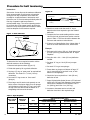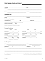
1
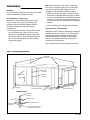
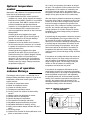
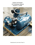
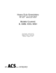
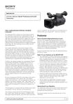
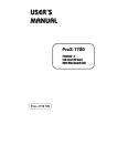
W AT E R
S O U R C E
H E AT
P U M P S
100 Percent Outside Air Units
Sizes 071 thru 381
Installation,
Operation
and Maintenance
Instructions
Important: These instructions are for the use of
specially trained personnel, experienced in the
installation of this equipment and related system
components. Some states require licensing of
installation and service personnel. Unqualified
individuals should not attempt to interpret these
instructions or install this equipment. Read
instructions carefully before unpacking, installing and
operating this heat pump unit.
and note any transit damage on all copies of the bill
of lading. Also inspect the unit for concealed shipping
damage after removing packaging. Transit damage
claims must be filed promptly with the freight
company by the purchaser.
Inspection: This heat pump has been factory
inspected prior to shipment. However, we
recommend you check the carton before unloading
Location: Unit must be installed indoors in any area
allowing adequate room for mounting of unit and with
access for maintenance and service.
Handling: Always handle with care and in the
horizontal position as shipped on the pallet. Moving
the heat pump on its side or dropping it may damage
internal parts.
Nomenclature
G - 141 - MHC
Voltage:
F = 208-230/60/3
G = 460/60/3
K = 575/60/3
J = 380/50/3
Mammoth is committed to a policy of
continuous. product improvements, and thus
reserves the right to.change specifications and
design without notice.
Unit Size (Nominal Cooling):
071 = 72,250 Btu/hr. cooling
111 = 111,000 Btu/hr. cooling
141 = 148,000 Btu/hr. cooling
181 = 183,000 Btu/hr cooling
221 = 226,000 Btu/hr cooling
271 = 270,000 Btu/hr cooling
321 = 330,000 Btu/hr cooling
381 = 381,000 Btu/hr cooling
Unit Type:
MHC = 100% Outside Air,
Standard Temperature Range
Design Series “C”
MLC = 100% Outside Air,
Low Temperature Geothermal,
Design Series “C”
Mammoth Inc.
© 1/2003 Mammoth Inc.
www.mammoth-inc.com
(P/N 71144921)
U-5
Note: Never attempt to raise, lower or adjust the
pitch of the unit by turning the units on the hanger
rods without first taking the weight of the unit
completely off the vibration isolation grommets.
Installation
Definition
Twin circuit 100% Outside Air unit with one fan outlet
and two independent refrigerant circuits.
Unit placement – ceiling hung
Mammoth’s 100% outside air heat pump can be
hung from the ceiling using the mounting rails
attached to the unit and with vibration isolation
grommets shipped inside the unit’s electric
compartment.
2. Mount the unit with a 5-degree (maximum) pitch
toward the condensate drain connection. Outside
air units are available with an optional bottom drain
connection. In the ceiling-mounted arrangement
this option will allow for more effective condensate
removal.
3. See unit data sheet for dimensional information.
Unit placement – slab-mounted
1. Fit the grommets into the 3⁄4-inch diameter holes
on the mounting rails. Use 5⁄16-inch or 3⁄8-inch
threaded rods (supplied by others) to hang the
unit from the ceiling. Cover the entire bottom of
the 11⁄4-inch diameter grommet with a washer
(supplied by others).
Mammoth’s 100% outside air heat pump can also be
installed on a flat level surface. It is recommended
that vibration mounts be placed under the unit to
prevent transmission of vibrating to the building
structure. The standard side drain connection is
required in this arrangement.
See unit data sheet for further dimensional details.
Figure 1. Ceiling-hung placement
Threaded Rod
(By Others)
Low Voltage
Connection
Water Out
Main Power
Connection
Water In
Mounting Rail
Condensate Connection
See Grommet
Detail
Mounting Rail
GROMMET DETAIL
Threaded Rod
(By Others)
Mounting Rail
Base
Retaining Nuts
(By Others)
Vibration Isolation Grommet
Washer (By Others) Must Cover
Entire Bottom of Grommet
2
U-5 IOM
Application limits
MINIMUM ENTERING WATER/BRINE
MAXIMUM ENTERING WATER
MINIMUM ENTERING AIR
MAXIMUM ENTERING AIR
COOLING
STD. TEMP. LOW TEMP.
55 F
30 F
110 F
110 F
60 F
60 F
100 F
100 F
MINIMUM ENTERING WATER/BRINE
MAXIMUM ENTERING WATER
MINIMUM ENTERING AIR
MAXIMUM ENTERING AIR
HEATING
STD. TEMP. LOW TEMP.
50 F
25 F
90 F
90 F
40 F*
40 F*
80 F
80 F
Only one maximum condition can exist at the same
time.
away from the unit for proper drainage by gravity and
as required by local codes. Condensate drains are
available as either standard side connection or
optional bottom connection.
Figure 2. Condensate trap detail – bottom drain
Bottom
of Unit
*Note: The minimum entering air temperature must
not fall below 40 F.
If the outside air is cooler than 40 F it must be
preconditioned or the unit must be shut off.
Mammoth offers both optional electric and hot water
preheat coils for this situation. See page 5 for
additional information on the heaters.
2-inch
Min. Trap
Figure 3. Condensate trap detail – side drain
Ductwork
Fasten the supply ductwork to the collar provided.
Use a flexible duct connection between the unit and
the supply duct. Make sure the blower wheel turns
freely and is centered before making the connection.
If a return air is used, it may be fastened to the
flanges on the filter guides. Make sure there is easy
access for filter replacement.
The discharge or supply air duct should be insulated
and have at least on 90-degree bend prior to the first
discharge grille. Heat pump life expectancy and
efficiency depends on adequate airflow. For nominal
cfm information see unit data sheet.
Water supply
The heat pump must not be operated without water
flowing through its water-to-refrigerant heat
exchanger coils. Severe damage to the unit may
result.
7/8" O.D.
Condensate
3"
1.5-inch Min. Internal
Trap (By Others)
Closed loop systems
1. Unit should be left unconnected or isolated using
gate valves as the building water loop is initially
flushed.
2. Water system should be filled with 1 lb. trisodium
phosphate for every 50 gallons of water.
3. The piping should then be purged of trapped air,
supplemental heater set to maintain 110 F and the
solution circulated for approximately 8 hours.
For proper water flow rates, refer to the unit
specification sheet.
4. The system should then be drained completely
and the entire flushing process repeated, if
necessary.
Condensate drain
See Figures 2 and 3
5. After completely cleaned and drained, fill loop with
water at an alkaline level of approximatelly pH 7.5.
The condensate drain is set up for 7⁄8-inch O.D.
copper connection. The condensate pipe or hose
installed must have a minimum 3-inch trap in the
condensate line. All condensate piping must pitch
6. Connect heat pump the the piping loop.
U-5 IOM
7. Make sure all entrained air is purged from loop.
Determine that specified flow rate through each
unit is established.
3
Optional hose kits
The flexible water hoses are 2-foot stainless steel
hoses for water connections to the heat pump and
adapters. Use two properly sized wrenches, one on
the unit FPT fitting and one on the hexagonal fitting
on the hose, when connecting hoses. Do not use
wrench on hose or sleeve that crimps the fitting onto
the hose. Hoses must not be subjected to stress of
being pulled taut, twisted or kinked. Connections
should not be over tightened.
Before pressurizing the water system, closely inspect
hoses and fittings to be sure there are no cuts,
abrasions, twists, kinks, stretch and hoses will not be
in contact with any sharp surface or edge while in
use. Also available for heat pumps is a condensate
hose and two hose clamps.
Changing filters
The filters can be accessed from either side of the
unit. The filter access panels (see Figure 4) are held
in place by several sheet metal screws. After one of
the access panels have been removed the filters will
slide out.
The same access panel that allows access to the
standard 2-inch filters also allows access to the
optional 4-inch thick panel filters.
Figure 4. Access panels
Preheat Section
For Mammoth hose kit information as to installation
and specifications, see data sheets C-91 and C-93.
Electric supply
Electrical service and fuses
Warning: Turn off electrical power before servicing
controls. Severe electrical shock may result unless
power is turned off.
Unit must be installed in compliance with NEC and
local codes.
Filter Access Section
Route wires through a properly sized disconnect
switch. Consult the wiring diagrams that are found in
this manual and inside the cover of the electrical box
to complete the connection. see nameplate for proper
fuse sizing, minimum circuit ampacity and voltage
requirements. An auxiliary electrical heater must be
installed with a power supply separate from the heat
pump.
All factory installed electric preheat coils require a
separate power supply. See the unit specification
sheet for more information.
Control wiring
All of the heat pump functions are controlled by
remote thermostat and must be wired as shown,
using approved 18-gauge copper wire.
4
U-5 IOM
The preheat section is located after the outside air
damper section and the filter section. It can be
access via access panels on either side of the heat
pump (see Figure 4).
The heater includes its own control box separate
from the unit’s electrical panel. It is mounted on the
outside of the unit casing, which houses all the heater
control components and safety devices. The heater is
U.L. listed. A separate power source from the unit is
required.
Electric Preheat — Optional
Hot Water Preheat — Optional
The Mammoth 100% Outdoor Air unit provides
optional electric heat to preheat the outdoor air to a
point where efficient compressor heating can take
place.
The Mammoth 100% Outdoor Air unit provides
optional hot water coils to preheat cold outdoor air to
a point where efficient compressor heating can take
place.
The electric heater is a pre-assembled package
designed to be installed internal to the unit. The
elements are constructed of nichrome wire and
include thermal limits, duct high limit, air proving
switch, and nonfused disconnect switch. The heater
operation is determined by outside air temperature, to
maintain a minimum 40 F entering air temperature to
the airside coil.The minimum entering air temperature
to the air coil is 40 F to allow operation of the
mechanical refrigeration for heating.
The hot water coil is constructed of aluminum fins
bonded to seamless copper tubes.
Optional preheat section
Units with the optional temperature control system
include a two-way, two-position, spring return valve
actuator. The valve actuator is controlled to maintain
a minimum 40 F entering air temperature to the air
coil to allow operation of the mechanical refrigeration
for heating. A freezestat closes the outdoor air
dampers and stops the fan and compressor if mixed
air is below 33 F.
Figure 5. Optional preheat wiring diagram
U-5 IOM
5
Figure 6. 100% outside air unit wiring diagram
CIRCUIT #1
COOLING ONLY (FIRST STAGE)
WITH HOT GAS REHEAT
(DEHUMIDIFICATION)
208/230 or 460 VOLTS
60 HERTZ, 3 PHASE
SEE NOTE 2
F
SEC
#1
COMPRESSOR
T3
T1
T2
BLACK
BLACK
BLACK
L3
T3
T2
T1
L3
L2
L1
1M
POWER
BLOCK
HP
L2
L1
SEE NOTES
1, 4 & 5
75 VA
CS
TRANSFORMER
#2
SEE NOTES
1, 4 & 5
50 VA
LP
TRANSFORMER
#1
24 VAC
3
24 VAC
BLUE
YELLOW
4
1R
1
5
2
TERMINAL
STRIP
24 VAC
COMPRESSOR #1
PINK/BLACK STRIPE
C1
R
YELLOW
Y1
COMPRESSOR #2
FAN
REVERSING VALVE (CIRCUIT #2)
G
RESET LIGHT
L
Y2
BLUE
PINK
O
DEHUMIDIFICATION (CIRCUIT #1)
BLUE
BLACK
PURPLE
H
ORANGE
E
C2
PINK/BLACK STRIPE
1
2
6
U-5 IOM
LEGEND:
CIRCUIT #2
FIRST STAGE HEATING
COND STAGE COOLING
Control Voltage Factory Wiring (24 VAC)
BLOWER
MOTOR
Control Voltage Field Wiring (24 VAC)
Line Voltage Factory Wiring
Line Voltage Field Wiring
#2
COMPRESSOR
T3
96
T1
Ground
SEE NOTE 3
T2
95
BLACK
BLACK
BLACK
BLACK
BLACK
BLACK
SEE NOTE 6
T3
L3
T2
T1
L1
L2
2M
T3
T2
L3
L2
T1
L1
1M
Compressor Contactor (Circuit #1)
2M
Compressor Contactor (Circuit #2)
3M
Blower Contactor
1R
Lockout Relay (Circuit #1)
2R
Lockout Relay (Circuit #2)
3R
Hot Gas Reheat Relay (Circuit #1)
4R
Cooling Relay (Circuit #2)
HR
Hot Gas Reheat Valve (Circuit #2)
3M
WT
HP
RV
Reversing Valve (Circuit #2)
HP
LP
CS
WT
High Pressure Switch (400 psi)
Low Pressure Switch (7 psi)
Condensate Switch (Optional)
Water Temperature Switch (32 F)
Optional (Circuit #2)
Damper Motor
Overload Relay (See Note 2)
Random Start Relay (25-60 Seconds)
Time Delay Relay (25-60 Seconds)
DM
OL
RS
TD
CS
TD
4
5
6
LP
S3
1
DM
1
3
2
3
4
RV
C1
C2
1
S1
2
5
2
4R
RS
CIRCUIT #2
3
1
3R
5
4
2R
2
HR
CIRCUIT #1
NOTES:
1. All units are factory-wired to customer order.
For 208 volt units, use the black and red transformer leads.
For 230 volt units, use the black and orange transformer leads.
For 460 volt units, use the black and black/red strip transformer leads.
2. Supply wiring must have copper conductors.
3. An external manual reset overload is used on all 5 HP through 20 HP blower
motors. All other blower motors have internal auto reset overloads.
4. Insulate all unused wire ends.
4. Both transformers must be phased identically: L1 is always the transformer’s black
lead.
5. The optional “Water Temperature Switch” (WT) is also included in the optional “Low
Temperature Package” (TL).
U-5 IOM
7
Figure 7. 100% outside air unit with hot water preheat wiring diagram
COOL
WI
(D
208/230 or 460 VOLTS
60 HERTZ, 3 PHASE
SEE NOTE 2
POWER
BLOCK
L3
L2
BLACK
L1
50 VA
TRANSFORMER
24 VAC
5
2
1
4
1
2
3
7R
D
DEHUMIDIFICATION
COMPRESSOR #1
YELLOW
Y1
Y2
COMPRESSOR #2
24 VAC
G
HOT GAS REHEAT
L
PURPLE
ORANGE
H
O
REVERSING VALVE
PINK
PINK/BLACK STRIPE
C1
LOCKOUT ALARM
BLUE
BLUE
R
FAN
WHITE
BLACK
5R
C2
C2
PINK/BLACK STRIPE
C1
5
4
6
2
CIRCUIT #2
RV
3
1
CIRCUIT #1
HV
8
U-5 IOM
CIRCUIT #2
1ST STAGE HEATING
2ND STAGE COOLING
CIRCUIT #1
LING ONLY (FIRST STAGE)
TH HOT GAS REHEAT
DEHUMIDIFICATION)
#1
COMPRESSOR
L3
L1
Control Voltage Factory Wiring (24 VAC)
Control Voltage Field Wiring (24 VAC)
#2
COMPRESSOR
L1
L3
L2
LEGEND:
BLOWER
MOTOR
96
Line Voltage Factory Wiring
SEE NOTE 3
OL
L2
Line Voltage Field Wiring
95
Ground
T3
T2
T1
T3
T2
T1
L3
L2
L1
1M
T2
T1
Compressor Contactor (Circuit #1)
2M
L3
L2
L1
Compressor Contactor (Circuit #2)
3M
Blower Contactor
1R
Lockout Relay (Circuit #1)
2R
Lockout Relay (Circuit #2)
3R
Lockout Signal Relay
4R
Hot Gas Reheat Relay (Circuit #1)
5R
Cooling Relay (Circuit #2)
6R
Low Temperature Lockout Relay
7R
Dehumidification Lockout in Heating Mode Relay
HR
Hot Gas Reheat Valve (Circuit #1)
RV
4-Way Reversing Valve (Circuit #2)
HP
CS
BLACK
T3
3M
WT
HP
CS
TD
LP
LP
HP
LP
CS
WT
RS
TD
LTC
RPB
ADT
DM
OL
75 VA
TRANSFORMER
3
24 VAC
1M
2M
L1
L2
SEE NOTE 4
L3
1R
3
1
5
1
2R
5
2
2
4
4
S3
S1
3R
1
DM
RS
3
High Pressure Switch (400 psi)
Low Pressure Switch (7 psi)
Condensate Switch (Optional)
Water Temperature Switch (Optional)
Random Start Relay (25-60 Seconds)
Time Delay Relay (25-60 Seconds)
Low Temperature Cutout
Reset Push Button
Adjustable Delay-on-Make Timer
Damper Motor
Overload (See Note 3)
2
1
5
2
5
1
6
2
3
1
6R
C1
C2
LTC
RPB
C
M1
SEE NOTE 6
3
4
LINE
ADT
N.C.
3
1
(240 SECONDS)
4R
2
5
1
NOTES:
1. All units are factory-wired to customer order.
For 208 volt units, use the black and red transformer leads.
For 230 volt units, use the black and orange transformer leads.
For 460 volt units, use the black and black/red strip transformer leads.
2. Supply wiring must have copper conductors.
3. An external manual reset overload is used on all 5 HP through 20 HP blower motors. All other blower motors have internal auto reset overloads.
4. The optional “Water Temperature Switch” (WT) is also included in the optional “Low Temperature Package” (TL).
5. Both transformers must be phased identically: L1 is always the transformer’s black lead.
6. If “Low Temperature Cutout Switch” (P/N 71042410) is factory set at 33 F. Its bulb is positioned across the discharge side of the preheat coil.
7. Insulate all unused wire ends.
U-5 IOM
9
Figure 8. 100% outside air unit with Johnson Metasys controls and electric preheat wiring diagram
SEE NOTE 5
10V
ELECTRIC
PREHEAT CONTROLS
8 7 6 5 4 3 2 1
1 2 3 4 5 6
2
2V
1 2 3 4 5 6
SEE NOTE 10
JOHNSON CONTROLS, INC.
METASYS
MODEL AS-UNT110-1
OFF
WHITE
BLACK
V
(10 VA POWER REQUIREMENT)
Z BUS
BO 5
BO 6
BO 7
BO 8
COMMON
COMMON
COMMON
BO 4
COMMON
BO 3
TRIACS
COMMON
BO 1
BO 2
24 VAC
24 VAC
REF
N2+
B14
24 VAC
N2–
B13
24 VAC
L2
BINARY OUTPUTS
P6
ZBUS
B12
24 VAC
COM
B11
24 VAC
P5
24 VAC
AI 6
15 VDC
AI COM
BINARY
INPUTS
15 VDC
AI 5
AI COM
TO
ZONE
STAT
L3
AI COM
AI 3
AI 4
AI COM
AI 1
AI 2
AI COM
SEE NOTE 6
ANALOG INPUTS
AI COM
208/230 OR
460 VOLTS
60 HERTZ
3 PHASE
SEE NOTE 2
1
ON
OFF
RED
T
C
2
2
L1
5
1
SEE NOTE 9
4
4
3
3
7R
5
6R
1
24 VAC
(BETWEEN THE ELECTRIC PREHEAT AND EVAPORATOR COILS)
TERMINAL
STRIP
HS
1
COM
2
POWER
E
OT
TEMP
YELLOW
Y1
Y2
BLUE
R
(ON THE RETURN AIR DUCT FLANGE
UPSTREAM OF THE AIR DAMPERS)
G
H
RED
YELLOW
O
AF
(SET @ 0.25")
(IN THE DISCHARGE AIR DUCTWORK)
C2
ORANGE
PURPLE
L
(IN THE DISCHARGE AIR DUCTWORK)
PINK
PINK/BLACK STRIPE
C1
DA
BLUE
BLACK
3
1
5
RV
10
5R
PINK/BLACK STRIPE
2
U-5 IOM
4
BLUE
YELLOW
WHITE
SEE NOTE 4
TEMP
#2
50 VA
TRANSFORMER
PINK/BLACK STRIPE
OUT
BLACK
SEE NOTES
1, 8 & 11
GRAY
MA
LEGEND:
Control Voltage Factory Wiring (24 VAC)
CIRCUIT #1
#2
COMPRESSOR
T3
T2
T1
T1
T1
L1
T3
L3
1M
T2
L2
Line Voltage Field Wiring
Ground
OL
SEE NOTE 3
96
T1
L1
2M
T3
L3
WT
HP
T2
L2
T1
L1
3M
HP
CS
BLACK
SEE NOTES
1, 8 & 11
2
Line Voltage Factory Wiring
95
SEE NOTE 7
T2
L2
BLOWER
MOTOR
1ST STAGE HEATING
2ND STAGE COOLING
#1
COMPRESSOR
T2
T3
T3
L3
Control Voltage Field Wiring (24 VAC)
CIRCUIT #2
COOLING ONLY (1ST STAGE)
WITH HOT GAS REHEAT
(DEHUMIDIFICATION)
CS
#1
75 VA
TRANSFORMER
3
24 VAC
1R
3 2R 1
1
BLUE
YELLOW
5
TD
5
2
2
4
Compressor Contactor (Circuit #1)
2M
Compressor Contactor (Circuit #2)
3M
Blower Contactor
1R
Lockout Relay (Circuit #1)
2R
Lockout Relay (Circuit #2)
3R
Lockout Signal Relay
4R
Hot Gas Reheat Relay (Circuit #1)
5R
Cooling Relay (Circuit #2)
6R
Stage #1 Electric Preheat Relay (PE)
7R
Stage #2 Electric Preheat Relay (PE)
HV
Hot-Gas Reheat Valve (Circuit #1)
RV
4-Way Reversing Valve (Circuit #2)
HP
LP
CS
WT
RS
TD
DM
OL
AF
DA
HS
MA
OT
LP
LP
1M
4
S3
RS
S1
High Pressure Switch (400 psi)
Low Pressure Switch (7 psi)
Condensate Switch (Optional)
Water Temperature Switch (Optional)
Random Start Relay (25-60 Seconds)
Time Delay Relay (25-60 Seconds)
Damper Motor
Overload (See Note 3)
Airflow Sensor
Discharge Air Sensor
Humidistat (See Note 4)
Mixed Airflow
Outdoor Thermostat (See Note 4)
1
DM
2
1
3
3R
5
2
3
4
4R
2
4
5
1
HV
U-5 IOM
NOTES:
1. All units are factory-wired to customer order.
For 208 volt units, use the black and red transformer leads.
For 230 volt units, use the black and orange transformer leads.
For 460 volt units, use the black and black/red strip transformer leads.
2. Supply wiring must have copper conductors.
3. An external manual reset overload is used on all 5 HP blower motors. All other blower motors have auto reset overloads.
4. Both the HS and OT sensors are contained within one device.
5. JCI Metasys UNT110-1 uses a factory installed program.
6. This factory wired jumper between terminals BI1 and 24 VAC indicates occupied status.
7. The optional “Water Temperature Switch” (WT) is also included in the optional “Low Temperature Package” (TL).
8. Both transformers must be phased identically: L1 is always the transformer’s black lead.
9. Johnson Controls, Inc. supplied jumper wire. Remove this jumper wire only if using a separate load transformer (by others).
10. The use of three-conductor shielded cable is required between relays 6R and 7R and the electric preheat control panel’s terminal block.
11. Insulate all unused wire ends.
11
Figure 9. 100% outside air unit with Johnson Metasys controls and hot water preheat wiring diagram
SEE NOTE 5
10V
2V
T
V
208/230 OR
460 VOLTS
60 HERTZ
3 PHASE
SEE NOTE 2
8 7 6 5 4 3 2 1
1 2 3 4 5 6
ON
OFF
1 2 3 4 5 6
JOHNSON CONTROLS, INC.
METASYS
MODEL AS-UNT110-1
OFF
(10 VA POWER REQUIREMENT)
Z BUS
BO 7
BO 8
L1
COMMON
COMMON
BO 5
BO 4
BO 6
COMMON
COMMON
BO 3
TRIACS
COMMON
BO 1
BO 2
24 VAC
24 VAC
REF
N2+
N2–
L2
BINARY OUTPUTS
P6
ZBUS
24 VAC
P5
COM
B13
B14
24 VAC
B12
BINARY
INPUTS
24 VAC
B11
L3
24 VAC
24 VAC
AI 6
15 VDC
15 VDC
AI 5
AI COM
AI COM
AI 3
AI 4
AI COM
AI COM
AI 1
AI 2
AI COM
AI COM
SEE NOTE 6
ANALOG INPUTS
TO
ZONE
STAT
BLACK
SEE NOTES
1, 8 & 11
50 VA
MA
#
TRANSFORMER
24 VAC
SEE NOTE 4
TERMINAL
STRIP
HS
1
COM
OUT
2
POWER
E
OT
TEMP
TEMP
YELLOW
Y1
Y2
BLUE
R
(ON THE RETURN AIR DUCT FLANGE
UPSTREAM OF THE AIR DAMPERS)
G
H
RED
YELLOW
O
AF
(SET @ 0.25")
(IN THE DISCHARGE AIR DUCTWORK)
C2
ORANGE
PURPLE
L
(IN THE DISCHARGE AIR DUCTWORK)
PINK
PINK/BLACK STRIPE
C1
DA
BLUE
BLACK
3
5R
5
RV
2
NOTES:
1. All units are factory-wired to customer order.
For 208 volt units, use the black and red transformer leads.
For 230 volt units, use the black and orange transformer leads.
For 460 volt units, use the black and black/red strip transformer leads.
2. Supply wiring must have copper conductors.
3. An external manual reset overload is used on all 5 HP blower motors. All other blower motors have auto reset overloads.
4. Both the HS and OT sensors are contained within one device.
5. JCI Metasys UNT110-1 uses a factory installed program.
6. This factory wired jumper between terminals BI1 and 24 VAC indicates occupied status.
7. The optional “Water Temperature Switch” (WT) is also included in the optional “Low Temperature Package” (TL).
8. Both transformers must be phased identically: L1 is always the transformer’s black lead.
9. Johnson Controls, Inc. supplied jumper wire. Remove this jumper wire only if using a separate load transformer (by others).
10. The “Low Temperature Cutout” switch (P/N 71042410) is factory set at 33 F. Its bulb is positioned across the discharge side of the preheat coil.
11. Insulate all unused wire ends.
12
1
PINK/BLACK STRIPE
U-5 IOM
4
BLUE
YELLOW
(BETWEEN THE ELECTRIC PREHEAT AND EVAPORATOR COILS)
CIRCUIT #1
LEGEND:
CIRCUIT #2
COOLING ONLY (1ST STAGE)
WITH HOT GAS REHEAT
(DEHUMIDIFICATION)
BLOWER
MOTOR
1ST STAGE HEATING
2ND STAGE COOLING
#1
COMPRESSOR
T2
T3
Control Voltage Factory Wiring (24 VAC)
Control Voltage Field Wiring (24 VAC)
#2
COMPRESSOR
T3
T2
95
T1
T1
Line Voltage Factory Wiring
OL
SEE NOTE 3
Line Voltage Field Wiring
96
T2
L2
T1
L1
T3
L3
1M
T2
L2
T1
L1
SEE NOTE 7
Ground
T3
L3
2M
T2
L2
T1
L1
3M
HP
HP
CS
CS
LP
LP
BLACK
SEE NOTES
1, 8 & 11
#2
T3
L3
WT
#1
75 VA
TRANSFORMER
R
3 1R
24 VAC
1
3
YELLOW
BLUE
TD
5
2R
1
5
2
2
4
4
S3
1
DM
RS
S1
2
1M
Compressor Contactor (Circuit #1)
2M
Compressor Contactor (Circuit #2)
3M
Blower Contactor
1R
Lockout Relay (Circuit #1)
2R
Lockout Relay (Circuit #2)
3R
Lockout Signal Relay
4R
Hot Gas Reheat Relay (Circuit #1)
5R
Cooling Relay (Circuit #2)
6R
Low Temperature Lockout Relay
7R
Stage #2 Electric Preheat Relay (PE)
HV
Hot-Gas Reheat Valve (Circuit #1)
RV
4-Way Reversing Valve (Circuit #2)
HP
LP
CS
WT
RS
TD
DM
OL
AF
DA
HS
MA
OT
LTC
ADT
High Pressure Switch (400 psi)
Low Pressure Switch (7 psi)
Condensate Switch (Optional)
Water Temperature Switch (Optional)
Random Start Relay (25-60 Seconds)
Time Delay Relay (25-60 Seconds)
Damper Motor
Overload (See Note 3)
Airflow Sensor
Discharge Air Sensor
Humidistat (See Note 4)
Mixed Air Sensor
Outdoor Thermostat (See Note 4)
Low Temperature Cutout
Adjustable Delay-on-Make Timer
1
3
3R
5
2
5
4
6
4
2
3
1
6R
C1
LTC
4
2
C
5
M1
ADT
RPB
3
4R
LINE
C2
N.C.
3
1
1
SEE NOTE 10
(240 SECONDS)
HV
U-5 IOM
13
Several typical wiring diagrams have been
provided for this option (Figure 8 and Figure 9).
Startup information for the Johnson Metasys
controller is provided on page 15.
3. Temperature control by others which includes a
24-volt terminal strip for connection of a controller
to operate the compressors, fan motor, reversing
valve and reheat valve.
Several typical wiring diagrams have been
provided for this option (Figure 6 and Figure 7).
Consult the factory for a specific diagram. Startup
for controls by others is not provided in this
document. It is not common but it is possible to
operate a 100% OA unit using a thermostat with
humidity control (by others). Startup instructions
are provided on page 15.
Sequence of operation
Johnson Metasys
The Metasys control system is can be tied in to a
Metasys Building Automation System or it can be an
independent, stand-alone control system. The
system includes:
●
●
●
●
●
●
●
●
●
●
●
●
●
●
14
Outdoor air temperature sensor
Mixed air temperature sensor
Outdoor air humidity sensor
Discharge air temperature sensor
Cooling control from outdoor air and humidity
sensors
Heating control from discharge air sensor
Reheat control for discharge air
Neutral discharge air temperature
Fan operation from damper end switch
Adjustable temperature/humidity set points
Adjustable differential for heating, cooling
Spring return outdoor damper actuator with end
switch
Air proving switch
Optional Zone Terminal for field modification of set
points on stand-alone controls.
If the discharge air temperature is below the set point
(55 F and adjustable), the hot gas reheat valve will
be activated to provide hot refrigerant gas to the
reheat coil to increase the discharge air temperature.
If the discharge air temperature rises above the set
point of the discharge air temperature, the hot gas
reheat valve will be de-activated. If the outdoor air
temperature falls below the second stage cooling
control set point, the second stage cooling will be deactivated.
If the outdoor air humidity falls below the outdoor air
humidity set point, first stage cooling will remain on
until the outdoor air temperature is below the first
stage cooling set point. The first stage cooling will
remain on until the outdoor air humidity and
temperature are below their set points.
If the outdoor air temperature falls below the first
stage heating set point, the compressor will operate
in the heating mode. If the mixed air temperature falls
below the preheat set point (40 F and adjustable),
the optional preheat coil will be activated to provide
heating. If the mixed air temperature rises above the
set point, the preheat will be de-activated. If the
discharge temperature rises above the set point, the
compressor heating will be de-activated.
Figure 10. Metasys control points
and unit schematic
Damper Section
Outdoor Air Temp. Sensor
T
Airflow
H
M
DX Coil
2. A Johnson Metasys DDC controller that can be
used as a stand-alone controller or with a Johnson
Metasys BMS.
After the need for preheat is examined, the controller
then looks at the need for compressor cooling. If the
outdoor air is above the first stage cooling set point,
then the first stage compressor will operate in the
cooling mode. If the outdoor air humidity is above the
set point, the controller will energize stage one
cooling operation. On a further increase in outdoor
temperature, the second stage-cooling compressor
will be energized.
Hot Gas Reheat
1. An optional Mammoth DDC control system for
complete unit control. Wiring diagrams and startup
information for the MDDC controller is not provided
in this document. Each MDCC controller has an
individual Installation and Operation Manual
created for it. Contact Mammoth for more details.
Filters
Mammoth’s 100% Outdoor Air heat pump units offer
three choices of temperature control:
On a call for unit operation, the outdoor air damper
will open. The controller will first examine the mixed
air temperature. If the outdoor air is below the set
point of the mixed air sensor, the preheat will be
energized to increase the air temperature. When the
damper is fully open, the fan will run continuously.
Preheat
Optional temperature
control
Mixed Air Temp. Sensor
Outdoor Air Humidity Sensor
Fan/Motor Section
Airflow
D
Discharge Air Temp. Sensor
U-5 IOM
Operation
Startup using Mammoth DDC controls
Consult the factory for specific instructions for your
unit.
Startup with factory-mounted
Johnson Metasys controls
1. Turn power on.
2. The green light on the Johnson Metasys UNT
DDC controller should blink.
3. The outside air damper will open.
4. When the damper has opened 60-75%, the fan
will start.
5. Unit will operate according to the mixed air
temperature. If the mixed air temperature is
above the set point of the controller, the unit will
cool. If the outdoor air temperature is below the
set point of the controller, the unit will heat. Only
the fan will run if the mixed air is in the dead
band of the set points.
6. Plug the ZT (Zone Terminal) into the UNT
controller using the supplied phone cord. The
inputs listed on the left side of the ZT can be
monitored. The binary outputs are listed on the
right side of the ZT. A hash mark indicates a call
for that particular output to operate. Zone
Terminal controller is available as Mammoth part
number 73399930.
7. The adjustable set points are: Occupied Cooling,
Occupied Heating, Unoccupied Cooling and
Unoccupied Heating. To adjust the set point,
open the access cover on the bottom of the ZT
and push the button to the left of the four LEDs
(Monitor, Adjust, Time Schedule and Password)
until the adjust LED is lit. Adjust the set point up
or down within the program limitations using the
up and down arrows. Your set point will appear
next to the Actual Clg Set and Actual Htg Set.
8. While the unit is operating in the cooling mode
with both compressors, adjust the water flow to
obtain a 12 F temperature rise in the leaving
water temperature as compared to the entering
water temperature.
Note: Set point adjustment in #7 above may be
required to get both compressors on.
9. Check for clean filters. Replace if necessary.
Startup using thermostat
A special thermostat (supplied by others) will be
required for humidity control.
After installing the unit, connecting ductwork water,
condensate lines and the wiring as described in the
preceding instructions, the unit is ready for startup.
Check all wire connections in the unit and to the
external control devices
Make certain that the thermostat system switch is in
the “OFF” position and the fan switch is in the
“AUTO” position. Also, the electric box cover and
access panels should be mounted in place. Then turn
on the power to the unit.
Turn the thermostat fan switch to the “ON” position.
The unit blower should operate.
Note: Unit may not start for 2-5 minutes due to usage
of random start relays and/or anti-short cycle relays.
1. Check the airflow and make sure no supply grilles
or duct dampers are closed to restrict airflow.
2. Set the thermostat temperature setting low and
turn the system switch to the heating mode.
3. Increase the temperature setting low and turn the
system switch to the heating mode.
4. After operating the unit for approximately ten
minutes, check the air temperature rise between
supply and return airstreams. The minimum
temperature rise should be about 18 F.
5. Using a surface pyrometer or other device, check
the temperature of the entering and leaving water
temperatures at the unit. The recommended water
temperature drop between entering and leaving
water may range from 5 to 9 F at 45 F entering
water temperature (ENT) and from 8 to 15 F at
70 F EWT.
If any of the above conditions do not exist, one or
more of the following problems exist: low airflow, low
water flow or unit not performing properly (contact
service department for assistance.
Next set the thermostat system switch to cooling
mode and reduce temperature setting gradually until
unit starts. After operating the unit for a few minutes,
check if unit is functioning properly and providing
satisfactory cooling.
Note: Minimum dry bulb drop between supply and
return airstreams should be about 16 F. A water
temperature rise of 12 to 25 F could be anticipated at
relatively low water flow rates.
10. The unit is ready for continuous operation.
Note: Minimum dry bulb temperature drop between
supply and return airstreams should be about 16 F. a
water temperature rise of 12-25 F could be
anticipated at relatively low water flow rates.
U-5 IOM
15
Maintenance
Mammoth 100% Outside Air units may require more
frequent maintenance than standard water source
heat pumps.
Air filters
Do not operate the heat pump unit without an air
filter. Clean the filters as often as necessary or at
least once every three months and more frequently in
dusty or other unclean environments.
Note: Dirty filters will cause inefficient heat pump
performance.
Air coil and blower wheel
Check the air coil and blower wheel at least once
each year. More frequent cleaning of blower and heat
transfer surfaces may be required in locations with
dirty air to maintain airflow and peak operating
performance. Clean as often as necessary.
Caution: Disconnect electric power supply to heat
pump before removing cabinet access panels.
Compressor
The 100% Outdoor Air heat pumps have been
designed with switches that protect the unit’s
refrigerant system if refrigerant pressure exceeds
either high or low limits. If unsuitable pressure
16
occurs, the compressors will automatically shut
down. (Some thermostats will indicate a compressor
shutdown with a “reset” light.)
If the compressor shuts down, turn the controller
system switch to the “OFF” position. After
approximately 10 minutes turn the controller system
switch to “ON” and restart the unit. If the compressor
shuts down again after only brief operation, a
problem exists and qualified service personnel must
be called to provide service.
General service
Any repair or service on the unit may be performed
only by qualified service personnel.
Warranty
Mammoth’s Standard Limited Warranty on all Water
Source Heat Pumps will be in effect for the first 12
months after startup or 18 months from actual
shipment if no startup date is provided. Extended
warranties are also available for an additional charge.
Parts
Parts can be ordered from:
Mammoth Inc.
101 West 82nd Street
Chaska, MN 55318
Phone: (952) 361-2711
Fax: (952) 361-2629
U-5 IOM
Guidelines for refrigerant circuit diagnosis
Normal Conditions
Subcooling:
Superheat:
Discharge:
Head Pressure:
Suction Pressure:
Evap. Temperature:
Over-Charged Unit
Subcooling:
Superheat:
Discharge:
Head Pressure:
Suction Pressure:
10 to 12 F
8 to 12 F
140 to 150 F
210#
70#
38 to 55 F, or 10-20 F below
leaving air temperature
20 to 25 F
8 to 12 F
120 to 130 F
220# or higher than normal
80# or higher than normal
Under-Charged Unit
Subcooling:
6 to 8 F or lower than normal
Superheat:
25 to 30 F or higher than
normal
Discharge:
Over 200 F
Head Pressure:
180# or lower than normal
Suction Pressure: 25# if lost a lot of refrigerant
Other:
Lower than normal evaporative
temperature
Low Evaporator Temperature
Undercharged.
● Poor refrigerant distribution.
● Low airflow (clogged filter or air coil).
● Excess oil in refrigerant air bypassing the coil.
● Damaged fins on the coil or poor fin-to-tube bond.
●
Subcooling in Cooling Mode
● Subcooled refrigerant is found after the coax and
before the TXV.
● The liquid line is almost always subcooled.
● The liquid line should be several degrees colder
than the leaving water temperature.
● Superheated refrigerant is found after the air coil
and before the compressor.
● Superheated refrigerant is found after the
compressor and before the coax.
High Suction Superheat
● Under-charged refrigerant circuit.
● Poorly adjusted TXV — open it.
● Plugged TXV.
● High entering air temp in the cooling mode.
Poorly insulated suction line.
Superheat:
normal
25 to 30 F or higher than
Low Suction Superheat
● Over-charged refrigerant circuit.
● Poorly adjusted TXV — close it.
● Low entering air temp in the cooling mode.
● Low airflow in the cooling mode.
Discharge:
Head Pressure:
Suction Pressure:
Other:
+200 F or warmer than normal
250# or higher than normal
45# or lower than normal
May have frost on air coil
May have high leaving air
temperature
The air coil may not be wet
Discharge Superheat
● High discharge superheat:
High suction superheat
Compressor lubrication problems
Compressor electrical problems
● Low discharge superheat:
Low suction superheat
Flooding-back
Plugged Thermal Expansion Valve
Subcooling:
15 to 20 F or higher than
normal
U-5 IOM
17
Procedure for belt tensioning
Instructions
Figure 12.
Set tension of new drives at the maximum deflection
force recommended. Check tension at least twice
during the first day of operation, since there will
normally be a rapid decrease in belt tension until
belts have run in. Check tension periodically after the
first day of operation and keep tension in
recommended range. The correct operating tension
for a V-belt drive is the lowest tension at which the
belts will not slip under peak load conditions. Shafts
must be adequate for the tensions required.
SPAN SCALE
Small
"O" Ring
Large
"O" Ring
6. Read force scale under the small “O” ring to
determine the force required to give the needed
deflection
Figure 11. Belt deflection
DEFLECTION =
FORCE SCALE
Belt Tension
Checker
7. Compare the force scale reading with the correct
value for the belt style and cross section used as
given in Table 1. The force should be between the
minimum and maximum values shown.
BELT SPAN
64
BELT S
PAN
8. If there is too little deflection force, tighten belts. If
there is too much deflection force, loosen belts.
Example
1. Belt span is 64 inches (152 cm). Small sleeve has
a 6-inch (152 mm) pitch diameter with “B” Super
Gripbelts.
2. Sixty-four inch ÷ 64 = 1 inch (25 mm) deflection
needed.
To determine lbs. force required to tension a drive
with belt tensioner, do the following:
3. Set large “O” ring at 1 inch (25 mm) on span
scale.
1. Measure belt span as shown (Figure 11).
4. Set small “O” ring at zero plunger.
2. Divide belt span by 64 to get belt deflection.
5. Press down on plunger until bottom of large “O”
ring is even with top of next belt in set, or with
bottom of a straightedge.
3. Set large “O” ring on “span scale” at required belt
deflection. This scale is in 1⁄16 inch (1.6 mm)
increments.
6. Check lbs. force required for a 1-inch (25 mm)
deflection of belt.
4. Set small “O” ring at zero on “force scale”
(plunger).
7. Super Gripbelt table (below) shows a “B” belt used
with 6-inch (152 mm) pitch diameter. Small sheave
should have a deflection force between 6 lbs. 6
oz. (2.89 kg) and 8 lbs. 8 oz. (3.97 kg).
5. Place larger end of tension tool squarely on one
belt at center of belt span. Apply force on plunger
until the bottom of the large “O” ring is even with
the top of the next belt or with the bottom of a
straightedge laid across the sheaves.
8. Increase or decrease tension on belts until
deflection force lies in the required range.
Table 1. Super Gripbelts
BELT CROSS
SECTION
SMALLEST
SHEAVE
4.4 – 5.6
B, BX
5.5 – 8.6
18
RPM
860 – 2500
DEFLECTION FORCE (LBS.)
SUPER GRIPBELTS
GRIPNOTCH BELTS
UNNOTCHED BRANDS
NOTCHED BRANDS
5.3
7.9
7.1
10.5
2501 – 4000
4.5
6.7
7.1
9.1
860 – 2501
6.3
9.4
8.5
12.6
2501 – 4001
6.0
8.9
7.3
11.9
U-5 IOM
Heat pump check-out sheet
Job Name ____________________________________________ Date ________________________________
Address ___________________________________________________________________________________
__________________________________________________________________________________________
Phone ______________________________________________ Unit No. _____________________________
Nameplate Data
Make _____________________________________________________________________________________
Model ______________________________________________ Serial No. ____________________________
R-22 Factory Charge_____oz.
Compressor RLA _____________________ LRA _____________________ Blower FLA __________________
Maximum Current Rating of Supply Circuit ______amps
Minimum Circuit Activity______amps
Branch Circuit Selection Current______amps
Running Conditions
HEAT
COOL
HEAT
COOL
Entering Air __________F ___________F
Leaving Air ___________F___________F __________cfm
Entering Water________F ___________F
Leaving Water_________F___________F _________GPM
Discharge___________PSI _________PSI
Suction _____________PSI__________PSI
Discharge____________F ___________F
Suction______________ F ___________F
Blower____________amps ________amps
Superheat____________ F ___________F
Compressor__________ F ___________F
Auxiliary Heat
Make _______________________________________________ Model _______________________________
Serial No. ____________________________________________ Maximum Fuse ____________________amps
Entering Air_________F
Leaving Air_________F
Comments _________________________________________________________________________________
__________________________________________________________________________________________
__________________________________________________________________________________________
__________________________________________________________________________________________
Form HP/COS-02
U-5 IOM
SAVE THIS FORM FOR MAINTENANCE REFERENCE .
19
Mammoth Inc.
▲ 101 West 82nd Street
▲ Chaska, Minnesota 55318-9663
▲ 952.361.2711 ▲ Fax 952.361.2870
▲ www.mammoth-inc.com