1
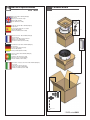
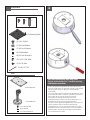
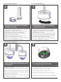
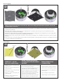
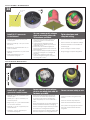
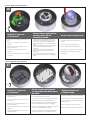
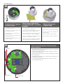
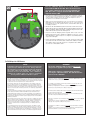
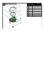
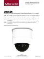
Installation and Operation Instructions
Before attempting to connect or operate this product, please
read these instructions completely.
SM5C8N
PoE Ready 5”Compact Vandal Resistant, Surface Mounted Dome Camera Enclosure
™
SM5C8N.........Outdoor 5” PoE surface mount housing for small PTZ camera, conduit input from the side and top of the housing, 30W PoE input, with heater
(SM5T8N) and Dynamic Power Allocation™. Polycarbonate body and clear/tinted dome. IP66, 1” NPT threads for pendant mount.
SM5CF8N.......Outdoor 5” PoE surface mount housing for small fixed camera, conduit input from the side and the top of the housing, 30W PoE input, with
(SM5TF8N) heater and Dynamic Power Allocation. Polycarbonate body and clear / tinted dome. IP66, 1” NPT threads for pendant mount.
SM5CF8NE......Outdoor 5” PoE surface mount housing for small fixed camera, conduit input from the side and the top of the housing 30W PoE input, with
(SM5TF8NE) heater and Dynamic Power Allocation. Polycarbonate body and clear / tinted dome. IP66, 1” NPT threads for pendant mount.
(no midspan included) SM5C8NE.......Outdoor 5” PoE surface mount housing for small PTZ camera, conduit input from the side and the top of the housing 30W PoE input, with
(SM5T8NE) heater and Dynamic Power Allocation. Polycarbonate body and clear/tinted dome. IP66, 1” NPT threads for pendant mount.
(no midspan included)
Substitute “C” (Clear dome) for “T” (Tinted dome) version
Moog Inc.
Sensor and Surveillance Systems
© 2013, Moog Inc. All Rights Reserved
3650 Woodhead Drive Northbrook, IL. USA 60062
+1.847.498.0700 Fax: +1.847.498.1258 www.moogS3.com
81-IN5460 111313
IMPORTANT SAFEGUARDS
1
Read these instructions.
2
Keep these instructions.
3
Heed all warnings
4
Follow all instructions.
5
Do not use this apparatus near water.
6
Clean only with damp cloth.
7
CAUTION
RISK OF ELECTRIC SHOCK
DO NOT OPEN
Do not block any of the ventilation openings. Install in accordance with the
manufacturers instructions.
8
9
SAFETY PRECAUTIONS
Cable Runs- All cable runs must be within permissible distance.
CAUTION: TO REDUCE THE RISK OF
ELECTRIC SHOCK, DO NOT REMOVE
COVER ( OR BACK). NO USER- SERVICEABLE PARTS INSIDE. REFER SEVICING
TO QUALIFIED SERVICE PERSONNEL.
Mounting - This unit must be properly and securely mounted to a supporting
structure capable of sustaining the weight of the unit.
Accordingly:
a. This installation should be made by a qualified service person and should conform
to all local codes.
b. Care should be exercised to select suitable hardware to install the unit, taking into
account both the composition of the mounting surface and the weight of the unit.
10 Do not install near any heat sources such as radiators, heat registers, stoves, or other
apparatus ( including amplifiers) that produce heat.
11 Do not defeat the safety purpose of the polarized or grounding-type plug. A
polarized plug has two blades with one wider than the other. A grounding type
plug has two blades and a third grounding prong. The wide blade or the third
prong are provided for your safety. When the provided plug does not fit into your
outlet, consult an electrician for replacement of the obsolete outlet.
12 Protect the power cord from being walked on or pinched particularly at plugs,
convenience receptacles, and the point where they exit from the apparatus.
13 Only use attachment/ accessories specified by the manufacturer.
14 Use only with a cart, stand, tripod, bracket, or table specified by the manufacturer,
or sold with the apparatus. When a cart is used, use caution when moving the cart/
apparatus combination to avoid injury from tip-over.
15 Unplug this apparatus during lighting storms or when unused for long periods of time.
16 Refer all servicing to qualified service personnel. Servicing is required when the
apparatus has been damaged in any way, such as power-supply cord or plug is
damaged, liquid has been spilled of objects have fallen into the apparatus, the
The lightning flash with an arrowhead symbol,
within an equilateral triangle, is intended to
alert the user to the presence of non-insulated
“dangerous voltage” within the product’s
enclosure that may be of sufficient magnitude
to constitute a risk to persons.
Este símbolo se piensa para alertar al usuario a la presencia
del “voltaje peligroso no-aisIado” dentro del recinto de los
productos que puede ser un riesgo de choque eléctrico.
Ce symbole est prévu pour alerter I’utilisateur à la presence
“de la tension dangereuse” non-isolée dans la clôture de
produits qui peut être un risque de choc électrique.
Dieses Symbol soll den Benutzer zum Vorhandensein der
nicht-lsolier “Gefährdungsspannung” innerhalb der
Produkteinschließung alarmieren die eine Gefahr des
elektrischen Schlages sein kann.
Este símbolo é pretendido alertar o usuário à presença “di
tensão perigosa non-isolada” dentro do cerco dos produtos
que pode ser um risco de choque elétrico.
Questo simbolo è inteso per avvertire I’utente alla presenza
“di tensione pericolosa” non-isolata all’interno della
recinzione dei prodotti che può essere un rischio di scossa
elettrica.
apparatus has been exposed to rain or moisture, does not operate normally, or
has been dropped.
Be sure to periodically examine the unit and the supporting structure to make sure that the integrity
of the installation is intact. Failure to comply with the foregoing could result in the unit separating
from the support structure and falling, with resultant damages or injury to anyone or anything struck
by the falling unit.
UNPACKING
Unpack carefully. Electronic components can be
damaged if improperly handled or dropped. If an item
appears to have been damaged in shipment, replace
it properly in its carton and notify the shipper.
Be sure to save:
1 The shipping carton and packaging material.
They are the safest material in which to make future
shipments of the equipment.
2 These Installation and Operating Instructions.
SERVICE
If technical support or service is needed, contact us at
the following number:
TECHNICAL SUPPORT
AVAILABLE 24 HOURS
1 - 800 - 554 -1124
The exclamation point within an equilateral
triangle is intended to alert the user to
presence of important operating and
maintenance (servicing) instructions in the
literature accompanying the appliance.
Este símbolo del punto del exclamation se piensa para
alertar al usuario a la presencia de instrucciones importantes
en la literatura que acompaña la aplicación.
Ce symbole de point d’exclamation est prévu pour alerter
l’utilisateur à la presence des instructions importantes dans
la littérature accompagnant l’appareil.
Dieses Ausruf Punktsymbol soll den Benutzer zum
Vorhandensein de wichtigen Anweisungen in der Literatur
alarmieren, die das Gerät begleitet.
Este símbolo do ponto do exclamation é pretendido alertar o
usuário à presença de instruções importantes na literatura
que acompanha o dispositivo.
Questo simbolo del punto del exclamaton è inteso per
avvertire l’utente alla presenza delle istruzioni importanti nella
letteratura che accompagna l'apparecchio.
MADEIN
USA
BUY AMERICA COMPLIANT • COUNTRY OF ORIGIN U.S.A.
Product Warranty Registration
Register Your Products Online
www.moogS3.com/technical-support/product-registration
Moog values your patronage. We are solely committed to providing you with the highest quality products and
superior customer service. With 3-Year and 5-Year warranties (depending on the product purchased) we stand
behind every product we sell.
See full warranty details at www.moogS3.com/technical-support/warranty-plan/
:
• Simple and Trouble-Free RMA process
• Product / software updates
• Special promotions
• Eliminate the need to archive purchase documents such as receipts, purchase orders, etc.
Limited Warranty for Moog Products
Moog - Decatur Operations, subsequently referred to as “Manufacturer,” warrants these products to be free from defects in material or workmanship as follows:
PRODUCT CATEGORY
PARTS \ LABOR
All Enclosures and Electronics
Five (5) Years
Accessory Brackets
Five (5) Years
Controllers
Three (3) Years
Power Supplies / IR Illuminators
Three (3) Years
Poles / PolEvators / CamEvator
Three (3) Years
Warrior Series / Q-View
Three (3) Years
™
™
™
Three (3) Years 6 months if used in auto scan / tour operation
SView Series™
DeputyDome , NiteTrac , Igloo Dome, PurgeDome
Three (3) Years 6 months if used in auto scan / tour operation
EXO Series™ Dome and Fixed Camera Systems*
Three (3) Years 6 months if used in auto scan / tour operation
EXO Series™ GeminEye Visible and Thermal Camera Systems
One (1) Year
™
™
™
During the labor warranty period, to repair the Product, Purchaser will either return the defective product, freight prepaid, or deliver it to Manufacturer at Moog Decatur
Operations, 2525 Park Central Boulevard, Decatur, Georgia, 30035. The Product to be repaired is to be returned in either its original carton or a similar package affording
an equal degree of protection with a RMA # (Return Materials Authorization number) displayed on the outer box or packing slip. To obtain a RMA# you must contact our
Technical Support Team at 800.554.1124, extension 101. Manufacturer will return the repaired product freight prepaid to Purchaser. Manufacturer is not obligated to
provide Purchaser with a substitute unit during the warranty period or at any time. After the applicable warranty period, Purchaser must pay all labor and/or parts charges.
The limited warranty stated in these product instructions is subject to all of the following terms and conditions.
TERMS AND CONDITIONS
1. NOTIFICATION OF CLAIMS: WARRANTY SERVICE: If Purchaser believes that the Product is defective in material or workmanship, then written notice with an explanation
of the claim shall be given promptly by Purchaser to Manufacturer. All claims for warranty service must be made within the warranty period. If after investigation,
Manufacturer determines the reported problem was not covered by the warranty, Purchaser shall pay Manufacturer for the cost of investigating the problem at its then
prevailing per incident billable rate. No repair or replacement of any Product or part thereof shall extend the warranty period of the entire Product. The specific warranty on
the repaired part only shall be in effect for a period of ninety (90) days following the repair or replacement of that part or the remaining period of the Product parts warranty,
whichever is greater.
2. EXCLUSIVE REMEDY: ACCEPTANCE: Purchaser’s exclusive remedy and Manufacturer’s sole obligation is to supply (or pay for) all labor necessary to repair any Product
found to be defective within the warranty period and to supply, at no extra charge, new or rebuilt replacements for defective parts.
3. EXCEPTIONS TO LIMITED WARRANTY: Manufacturer shall have no liability or obligation to Purchaser with respect to any Product requiring service during the warranty
period which is subjected to any of the following: abuse, improper use, negligence, accident, or acts of God (i.e., hurricanes, earthquakes), modification, failure of the
end-user to follow the directions outlined in the product instructions, failure of the end-user to follow the maintenance procedures recommended by the International Security
Industry Organization, written in product instructions, or recommended in the service manual for the Product. Furthermore, Manufacturer shall have no liability where a
schedule is specified for regular replacement or maintenance or cleaning of certain parts (based on usage) and the end-user has failed to follow such schedule; attempted
repair by non-qualified personnel; operation of the Product outside of the published environmental and electrical parameters, or if such Product’s original identification
(trademark, serial number) markings have been defaced, altered, or removed. Manufacturer excludes from warranty coverage Products sold AS IS and/or WITH ALL FAULTS
and excludes used Products which have not been sold by Manufacturer to the Purchaser. All software and accompanying documentation furnished with, or as part of the
Product is furnished “AS IS” (i.e., without any warranty of any kind), except where expressly provided otherwise in any documentation or license agreement furnished with
the Product. ANY COST ASSOCIATED WITH REMOVAL OF DEFECTIVE PRODUCT AND INSTALLATION OF REPLACEMENT PRODUCT IS NOT INCLUDED IN THIS WARRANTY.
4. PROOF OF PURCHASE: The Purchaser’s dated bill of sale must be retained as evidence of the date of purchase and to establish warranty eligibility.
DISCLAIMER OF WARRANTY
EXCEPT FOR THE FOREGOING WARRANTIES, MANUFACTURER HEREBY DISCLAIMS AND EXCLUDES ALL OTHER WARRANTIES, EXPRESS OR IMPLIED, INCLUDING, BUT
NOT LIMITED TO ANY AND/OR ALL IMPLIED WARRANTIES OF MERCHANTABILITY, FITNESS FOR A PARTICULAR PURPOSE AND/OR ANY WARRANTY WITH REGARD TO ANY
CLAIM OF INFRINGEMENT THAT MAY BE PROVIDED IN SECTION 2-312(3) OF THE UNIFORM COMMERCIAL CODE AND/OR IN ANY OTHER COMPARABLE STATE STATUTE.
MANUFACTURER HEREBY DISCLAIMS ANY REPRESENTATIONS OR WARRANTY THAT THE PRODUCT IS COMPATIBLE WITH ANY COMBINATION OF NON-MANUFACTURER
PRODUCTS OR NON-MANUFACTURER RECOMMENDED PRODUCTS PURCHASER MAY CHOOSE TO CONNECT TO THE PRODUCT.
LIMITATION OF LIABILITY
THE LIABILITY OF Manufacturer, IF ANY, AND PURCHASER’S SOLE AND EXCLUSIVE REMEDY FOR DAMAGES FOR ANY CLAIM OF ANY KIND WHATSOEVER, REGARDLESS
OF THE LEGAL THEORY AND WHETHER ARISING IN TORT OR CONTRACT, SHALL NOT BE GREATER THAN THE ACTUAL PURCHASE PRICE OF THE PRODUCT WITH RESPECT
TO WHICH SUCH CLAIM IS MADE. IN NO EVENT SHALL MANUFACTURER BE LIABLE TO PURCHASER FOR ANY SPECIAL, INDIRECT, INCIDENTAL, OR CONSEQUENTIAL
DAMAGES OF ANY KIND INCLUDING, BUT NOT LIMITED TO, COMPENSATION, REPLACEMENT LABOR COSTS, REIMBURSEMENT, OR DAMAGES ON ACCOUNT OF THE LOSS
OF PRESENT OR PROSPECTIVE PROFITS OR FOR ANY OTHER REASON WHATSOEVER.
* NOTE
Moog will repair or replace, at its option, any equipment which is damaged by transient voltage surge/spike or lightning strike (an “Occurrence”), while properly connected
to wired AC power line with protective ground. Any repair or modification of the equipment done by someone other than Moog voids the warranty.
Form 500-911 081913
!
Electrical Specifications
Power POE 56V
SM5C8N
Contents of Box
SM5CF8N
Input Power: 100 to 240VAC (Midspan)
Power: 0.8A
Frequency: 50 to 60 HZ output
Camera: POE (55VDC)
Heater: 56VDC (max. 20W)
*
English
(1) Mounting Plate
Energía de entrada: 100 a 240VAC (Midspan)
Energía: 0.8A
Frecuencia: 50 a 60 hertzios de salida
Cámara: POE (55VDC)
Calentador: 56VDC (máximo 20W)
(1) Fixed Bracket
Español
(7) 8 x 32 x 3/8" Bolt
(3) 8 x 32 Nuts
(7) 8 x 32 Star Washers
Français
Deutsch
Portuguese
Puissance d'entrée: 100 à 240VAC (Midspan)
Puissance: 0.8A
Fréquence: 50 à 60 hertz de rendement
Appareil-photo: POE (55VDC)
Réchauffeur: 56VDC (maximum 20W)
Zugeführte Energie: 100 zu 240VAC (Midspan)
Energie: 0.8A
Frequenz: 50 bis 60 Hz Ausgang
Kamera: POE (55VDC)
Heizung: 56VDC (Maximum 20W)
Poder de entrada: 100 a 240VAC (Midspan)
Poder: 0.8A
Freqüência: 50 a 60 hertz de saída
Câmera: Ponto de entrada (55VDC)
Calefator: 56VDC (máximo 20W)
Alimentazione in ingresso di entrata: 100 a 240VAC (Midspan)
Potere: 0.8A
Frequenza: 50 - 60 hertz di uscita
Macchina fotografica: POE (55VDC)
Riscaldatore: 56VDC (massimo 20W)
Italiano
(1) Mounting Plate
(1) 1/4 x 20 Bolt
(1) 1/4 Flat Washer
(1) 1/4 Lock Washer
(4) M3 6mm Bolt
(4) M3 Lock Washers
(7) 8 x 32 x 3/8" bolts
(2) 8 x 32 Nuts
(2) 94-FSCT01
* FIXED units ONLY
1
PACKETS
(4)
(8)
For Surface Mounting Using Side Conduit Entrance
(4)
(1) Mounting Plate
(1) 1/4 x 20 Bolt
(1) 1/4 Flat Washer
(1) 1/4 Lock Washer
(4) M3 6mm Bolt
(4) M3 Lock Washers
(7) 8 x 32 x 3/8" bolts
(2) 8 x 32 Nuts
(2) 94-FSCT01
Fixed
Etch knockout slightly with utility knife.
Knock and hammer out ⅞ conduit opening
with blunt screw driver
(1) Mounting Plate
(1) Fixed Bracket
(7) 8 x 32 x 3/8" Bolt
(3) 8 x 32 Nuts
(7) 8 x 32 Star Washers
• Golpe de gracia del grabado de pistas levemente
con el cuchillo para uso general. Golpee y resuelva la
abertura del conducto del ⅞ con destornillador
embotado
• Coup de grâce gravure à l'eau forte légèrement avec
le couteau de service. Frappez et résolvez l'ouverture
de conduit de ⅞ avec le tournevis émoussé
• Ätzung-Ausscheidungswettkampf etwas mit
Gebrauchsmesser. Klopfen Sie und hämmern Sie ⅞
Rohröffnung mit stumpfem Schraubenzieher
• KO gravura em àgua forte ligeiramente com faca de
serviço público. Bata e resolva a abertura da
canalização do ⅞ com chave de fenda sem corte
• Espulsore incissione all'acquaforte un po'con la lama
pratica. Batti e risolva l'apertura del condotto del ⅞
con il cacciavite smussato
For Surface Mounting Using Side Conduit Entrance Continued
2
WARNING: Ensure drill is
level to avoid damage to
the circuit board
For Surface Mount Applications
3
2
1
3
Drill out (3) mounting holes as shown for # 10
hardware (not supplied)
• Taladre (3) los agujeros de montaje como se
muestra para # el hardware 10 (not supplied)
• Percez (3) les trous de montage comme montré
pour # le matériel 10 (not supplied)
• Bohren Sie (3) Entlüftungslöcher wie gezeigt für
# Hardware 10 heraus (not supplied)
• Fure (3) furos de montagem como mostrado
para # a ferragem 10 (not supplied)
• Estragga (3) fori di montaggio come indicato
per # fissaggi 10 (not supplied)
For Surface Mount Applications
4
Connect conduit fitting to knockout.
• Conecte el conducto que cabe con el golpe de gracia.
• Reliez le conduit s'adaptant au coup de grâce.
• Schließen Sie das Rohr an, das an
Ausscheidungswettkampf passt.
Mount securely to ceiling or mounting
surface using the appropriate hardware
• Monte con seguridad a la superficie del techo
o de montaje usando el hardware apropiado
• Montez solidement au plafond ou à la surface
de montage utilisant le matériel approprié
• Bringen Sie sicher zur Decke oder zur Befestigungsfläche
unter Verwendung der passenden Hardware an
• Monte firmemente à superfície do teto ou de
montagem usando a ferragem apropriada
• Monti saldamente alla superficie di montaggio
o del soffitto per mezzo dei fissaggi adatti
For Pendant Or Wall Mount Bracket Applications
5
Remove plug with ⅝” Allen Wrench.
• Quite el enchufe con la llave Allen del ⅝”.
• Enlevez la prise clé Allen avec de ⅝ ».
• Entfernen Sie Stecker mit ⅝“ Inbusschlüssel.
• Conecte a canalização que cabe ao KO.
• Remova o plugue com chave Allen do ⅝ de”.
• Colleghi il condotto che si adatta all'espulsore.
• Rimuova la spina con chiave di Allen del ⅝„.
For Pendant Or Wall Mount Applications
For Pendant Or Wall Mount Applications
6
7
Seal pipe threads with teflon tape supplied
with outdoor housings.
Thread housing to optional pendent pipe
or wall mount bracket
• Hilos de rosca de pipa del sello con la cinta del Teflon
suministrada las cubiertas al aire libre.
• Filetages de tuyauterie de joint avec la bande de
teflon fournie avec les logements extérieurs.
• Dichtungsrohrgewinde mit dem Teflonklebeband
geliefert mit im Freiengehäusen.
• Linhas de tubulação do selo com a fita do Teflon
fornecida com as carcaças ao ar livre.
• Filetti di tubo della guarnizione con nastro adesivo del
Teflon fornito con gli alloggiamenti esterni.
• Hilo de rosca que contiene al soporte pendiente
opcional del montaje de la pipa o de la pared
• Fil logeant à la parenthèse en suspens facultative
de bâti de pipe ou de mur
• Gewinde, das zum wahlweise freigestellten pendent
Rohr- oder Wandeinfassungshaltewinkel unterbringt
• Linha que abriga ao suporte pendent opcional da
montagem da tubulação ou da parede
• Filetto che alloggia alla staffa pendent facoltativa
del supporto della parete o del tubo
For Pendant Or Wall Mount Applications
8
9
Finish assembly with Pendant or Wall mount
(not supplied).
Feed wiring through threaded hole.
• Asamblea del final con el montaje pendiente o de la
pared (not supplied).
• Finition avec le bâti en suspens ou de mur (not supplied).
• Cableado de la alimentación a través del agujer roscado.
• Câblage d'alimentation par le trou fileté.
• Ende mit Pendent oder Wandeinfassung (not supplied).
• Zufuhrverdrahtung durch verlegtes Loch.
• Conjunto do revestimento com a montagem Pendent
ou da parede (not supplied).
• Fiação da alimentação através do furo rosqueado.
• Assemblea di rivestimento con il supporto della parete
o Pendent (not supplied).
• Collegamenti dell'alimentazione attraverso il foro filettato.
Arecont AV1315 / AV2815 / AV2805 / AV10005 Camera
10
REMOVE
Remove center section from fixed camera bracket. Attach to mounting plate with hardware provided. Secure and
complete wiring connections.
• Quite la sección de centro del soporte fijo de la cámara. Ate a la pletina con el hardware proporcionado. Asegure y termine las
conexiones del cableado.
• Enlevez la section centrale de la parenthèse fixe d'appareil-photo. Attachez au plat de support avec le matériel fourni. Fixez et
accomplissez les raccordements de câblage.
• Entfernen Sie mittleren Abschnitt von örtlich festgelegtem Kamerahaltewinkel. Bringen Sie zur Montageplatte mit der bereitgestellten
Hardware an. Sichern Sie und schließen Sie Verdrahtungsanschlüsse ab.
• Remova a seção center de suporte fixo da câmera. Una à placa de montagem com a ferragem fornecida. Fixe e termine conexões
da fiação.
• Rimuova la sezione concentrare dalla staffa fissa della macchina fotografica. Attacchi al giunto di supporto con fissaggi forniti. Assicuri
e completi i collegamenti dei collegamenti.
Axis M10 Camera Series
11
12
Axis M-10
Camera hole
pattern
Axis 207
Adding
Spacers
Attach Axis camera mount to camera base plate. Use (4) 1” spacers and attach camera base plate to housing.
• Ate el montaje de cámara del eje al embase de la cámara. Utilice (4) los” espaciadores 1 y ate el embase de la cámara a la
cubierta.
• Attachez la monture de caméra d'axe à l'embase d'appareil-photo. Employez (4) les » entretoises 1 et attachez l'embase d'appareilphoto au logement.
• Bringen Sie Mittellinienkameraeinfassung zur Grundplatte der Kamera an. Verwenden Sie (4)“ Distanzscheiben 1 und bringen Sie
Grundplatte der Kamera zum Gehäuse an.
• Una a montagem de câmera da linha central à placa baixa da câmera. Use (os” espaçadores 4) 1 e una a placa baixa da câmera
à carcaça.
• Attacchi il supporto di macchina fotografica di asse alla base di appoggio della macchina fotografica. Usi (4)„ i distanziatori 1 ed
attaccano la base di appoggio della macchina fotografica ad alloggiamento.
Axis 212 PTZ Camera
12
(13mm) ½"
(52mm) 2"
Remove center section from fixed camera bracket. Attach to mounting plate with hardware provided. Secure and
complete wiring connections.
• Quite la sección de centro del soporte fijo de la cámara. Ate a la pletina con el hardware proporcionado. Asegure y termine las
conexiones del cableado.
• Enlevez la section centrale de la parenthèse fixe d'appareil-photo. Attachez au plat de support avec le matériel fourni. Fixez et
accomplissez les raccordements de câblage.
• Entfernen Sie mittleren Abschnitt von örtlich festgelegtem Kamerahaltewinkel. Bringen Sie zur Montageplatte mit der bereitgestellten
Hardware an. Sichern Sie und schließen Sie Verdrahtungsanschlüsse ab.
• Remova a seção center de suporte fixo da câmera. Una à placa de montagem com a ferragem fornecida. Fixe e termine conexões
da fiação.
• Rimuova la sezione concentrare dalla staffa fissa della macchina fotografica. Attacchi al giunto di supporto con fissaggi forniti. Assicuri
e completi i collegamenti dei collegamenti.
Axis 216 Camera
13
(13mm) ½"
Use this hole
pattern
(52mm) 2"
Install (4) .5” + (4) 2.0”
spacers to center bosses.
• Instale (4) .5” + (4) 2.0” espaciadores para
centrar los jefes.
Secure camera quick release
mounting plate with #8 hardware
provided.
• Pletina segura del lanzamiento rápido de la cámara
con el hardware #8 proporcionado.
Tighten hardware and
complete wiring.
• Apriete el hardware y termine el cableado.
• Installez (4) .5 » + (4) 2.0 » entretoises pour
centrer des patrons.
• Le plat de support bloqué de dégagement rapide
d'appareil-photo avec le matériel #8 a fourni.
• Serrez la visserie et accomplissez le câblage.
• Bringen Sie (4) .5“ + (4) 2.0“ Distanzscheiben
an, um Chefs zu zentrieren.
• Sichere Montageplatte der schnellen Freigabe der
Kamera mit Hardware #8 stellte zur Verfügung.
• Ziehen Sie Hardware fest und schließen Sie
Verdrahtung ab.
• Instale (4) .5” + (4) 2.0” espaçadores para
centrar saliências.
• Placa de montagem segura da liberação rápida
da câmera com a ferragem #8 fornecida.
• Aperte a ferragem e termine a fiação.
• Installi (4) .5„ + (4) 2.0„ distanziatori per
concentrarsi le sporgenze.
• Il giunto di supporto sicuro del rilascio rapido della
macchina fotografica con fissaggi #8 ha fornito.
• Stringa i fissaggi e completi i collegamenti.
Panasonic BB-HCM381 / KX-HCM280A Camera
14
Use this hole
pattern
Install (4) .5” spacers to
center bosses.
• Instale (4) espaciadores del .5 los” para
centrar los jefes.
• Entretoises installez (4) .5 des » pour centrer
des patrons.
• Bringen Sie (4) .5“ Distanzscheiben an, um
Chefs zu zentrieren.
• Instale (4) espaçadores do .5” para centrar
saliências.
• Installi (4) distanziatori del .5„ per
concentrarsi le sporgenze.
(13mm) ½"
Secure camera quick release
plate to mounting plate with
#8 hardware provided.
• Placa segura del lanzamiento rápido de la
cámara a la pletina con el hardware #8
proporcionado.
• Le plat bloqué de dégagement rapide
d'appareil-photo au plat de support avec le
matériel #8 a fourni.
• Sichere Platte der schnellen Freigabe der
Kamera zur Montageplatte mit der Hardware
#8 bereitgestellt.
• Placa segura da liberação rápida da câmera
à placa de montagem com a ferragem #8
fornecida.
• Il piatto sicuro del rilascio rapido della
macchina fotografica al giunto di supporto
con fissaggi #8 ha fornito.
Tighten hardware and
complete wiring.
• Apriete el hardware y termine el cableado.
• Serrez la visserie et accomplissez le câblage.
• Ziehen Sie Hardware fest und schließen Sie
Verdrahtung ab.
• Aperte a ferragem e termine a fiação.
• Stringa i fissaggi e completi i collegamenti.
Panasonic WV-SF304 / WV-SF336 Camera
15
(13mm) ½"
(52mm) 2"
Install (4) .5” + (4) 2.0”
spacers to center bosses.
Secure camera quick release
plate to mounting plate with #8
hardware provided.
• Instale (4) .5” + (4) 2.0” espaciadores para
centrar los jefes.
• Pletina segura del lanzamiento rápido de la
cámara con el hardware #8 proporcionado.
• Installez (4) .5 » + (4) 2.0 » entretoises pour
centrer des patrons.
• Le plat de support bloqué de dégagement
rapide d'appareil-photo avec le matériel #8 a
fourni.
• Bringen Sie (4) .5“ + (4) 2.0“ Distanzscheiben
an, um Chefs zu zentrieren.
• Sichere Montageplatte der schnellen Freigabe der
Kamera mit Hardware #8 stellte zur Verfügung.
• Instale (4) .5” + (4) 2.0” espaçadores para
centrar saliências.
• Placa de montagem segura da liberação rápida
da câmera com a ferragem #8 fornecida.
• Installi (4) .5„ + (4) 2.0„ distanziatori per
concentrarsi le sporgenze.
• Il giunto di supporto sicuro del rilascio rapido della
macchina fotografica con fissaggi #8 ha fornito.
Secure camera safety screw.
• Asegure el tornillo de la seguridad de la
cámara.
• Fixez la vis de sûreté d'appareil-photo.
• Sichern Sie Kamerasicherheitsschraube.
• Fixe o parafuso da segurança da câmera.
• Fissi la vite di sicurezza della macchina
fotografica.
Panasonic WV-NF284 / WV-NF302 Camera
16
(25mm) 1"
Install (4) 1” spacer to
center bosses.
• Instale (4) 1” espaciador para centrar los
jefes.
• Installez (4) 1 » entretoise pour centrer des
patrons.
• Bringen Sie (4) 1“ Distanzscheibe an, um
Chefs zu zentrieren.
• Instale (4) 1” espaçador para centrar
saliências.
• Installi (4) 1„ distanziatore per concentrarsi le
sporgenze.
Secure camera quick release
mounting plate with #8
hardware provided.
• Pletina segura del lanzamiento rápido de la
cámara con el hardware #8 proporcionado.
• Le plat de support bloqué de dégagement
rapide d'appareil-photo avec le matériel #8 a
fourni.
• Sichere Montageplatte der schnellen Freigabe
der Kamera mit Hardware #8 stellte zur
Verfügung.
• Placa de montagem segura da liberação
rápida da câmera com a ferragem #8
fornecida.
• Il giunto di supporto sicuro del rilascio rapido
della macchina fotografica con fissaggi #8 ha
fornito.
Secure camera safety screw.
• Asegure el tornillo de la seguridad de la
cámara.
• Fixez la vis de sûreté d'appareil-photo.
• Sichern Sie Kamerasicherheitsschraube.
• Fixe o parafuso da segurança da câmera.
• Fissi la vite di sicurezza della macchina
fotografica.
Panasonic WV-NS202 / WV-SC385 Camera
17
(13mm) ½"
Install (4) .5” spacers to
center bosses.
Secure camera quick release
mounting plate with #8 hardware
provided.
• Instale (4) espaciadores del .5 los” para
centrar los jefes.
• Pletina segura del lanzamiento rápido de la cámara
con el hardware #8 proporcionado.
• Entretoises installez (4).5 des » pour centrer
des patrons.
• Le plat de support bloqué de dégagement rapide
d'appareil-photo avec le matériel #8 a fourni.
• Bringen Sie (4) .5“ Distanzscheiben an, um
Chefs zu zentrieren.
• Sichere Montageplatte der schnellen Freigabe der
Kamera mit Hardware #8 stellte zur Verfügung.
• Instale (4) espaçadores do .5” para centrar
saliências.
• Placa de montagem segura da liberação rápida da
câmera com a ferragem #8 fornecida.
• Installi (4) distanziatori del .5„ per concentrarsi le sporgenze.
• Il giunto di supporto sicuro del rilascio rapido della
macchina fotografica con fissaggi #8 ha fornito.
Tighten hardware and
complete wiring.
• Apriete el hardware y termine el cableado.
• Serrez la visserie et accomplissez le câblage.
• Ziehen Sie Hardware fest und schließen Sie
Verdrahtung ab.
• Aperte a ferragem e termine a fiação.
• Stringa i fissaggi e completi i collegamenti.
Toshiba IKWB21A Camera
18
(13mm) ½"
(26mm) 1"
1” spacers + (4) .5” spacers
(4) corner bosses.
Secure camera quick release
mounting plate with ¼” hardware
provided.
• 1” espaciadores + (4) jefes de la esquina de
los espaciadores del .5” (4).
• Pletina segura del lanzamiento rápido de la cámara
con el hardware ¼” proporcionado.
• 1 » entretoises + (4) patrons faisants le coin
des entretoises de .5 » (4).
• Le plat de support bloqué de dégagement rapide
d'appareil-photo avec le matériel ¼” a fourni.
• 1“ Distanzscheiben + (4) .5“ Eckchefs der
Distanzscheiben (4).
• Sichere Montageplatte der schnellen Freigabe der
Kamera mit Hardware ¼” stellte zur Verfügung.
• saliências de canto dos espaçadores de 1”
espaçadores + (4) .5” 4).
• Placa de montagem segura da liberação rápida da
câmera com a ferragem ¼” fornecida.
• i distanziatori del 1„ distanziatori + (4) .5„ (4)
sporgenze d'angolo.
Tighten hardware and
complete wiring.
• Apriete el hardware y termine el cableado.
• Serrez la visserie et accomplissez le câblage.
• Ziehen Sie Hardware fest und schließen Sie
Verdrahtung ab.
• Aperte a ferragem e termine a fiação.
• Stringa i fissaggi e completi i collegamenti.
• Il giunto di supporto sicuro del rilascio rapido della
macchina fotografica con fissaggi ¼” ha fornito.
19
Cable to camera (B), Network / Power (A). Unit is
ready to power up.
Power Reset
• Cablegrafíe a la cámara (b), red hacia / fuera (a). La unidad está
lista para accionar para arriba.
LEDs
• Câblez à l'appareil-photo (b), le réseau / dehors (a). L'unité est
prête à mettre sous tension.
• Kabeln Sie zu Kamera (b), Netz / heraus (a). Maßeinheit ist bereit,
oben anzutreiben.
• Cabografe à câmera (b), rede / para fora (a). A unidade está
pronta para pôr acima.
• Cavo alla macchina fotografica (B), rete / fuori (A). L'unità è
pronta ad alimentare in su.
B
A
Network to Camera
Network / Power In
20
Press the Calibration button for one second. Both the
Test and Heat LED will turn ON. Once the unit has been
successfully calibrated, the Test and Heat LED will turn
OFF. Once this is complete the Heat LED will turn ON
only if the heater is ON.
Reset
•
Pulse el botón de calibración durante un segundo. Tanto la prueba y el calor se
encenderá. Una vez que la unidad ha sido calibrado correctamente, la prueba y
el calor del LED se apagará. Una vez que se trata de completar el calor se
encenderá sólo si el calentador está encendido.
•
Appuyez sur le bouton d'étalonnage pour une seconde. Tant le test et la chaleur
LED s'allume. Une fois l'appareil a été étalonné avec succès, le test et la chaleur
LED s'éteindra. Une fois cette opération terminée, la chaleur LED s'allume que si
le chauffage est allumé.
• Drücken Sie die Taste Kalibrierung für eine Sekunde. Sowohl der Test-und
Wärme-LED leuchtet auf. Sobald das Gerät erfolgreich kalibriert wurde, wird
die Test-und Wärme-LED auszuschalten. Sobald dies abgeschlossen ist die
Wärme-LED leuchtet auf, wenn die Heizung an ist.
• Pressione o botão de calibração para um segundo. Tanto o teste como calor
LED acenderá. Uma vez que o aparelho foi calibrado com sucesso, o teste e
calor LED apaga-se. Uma vez que este é completar o calor LED acenderá se
o aquecedor está ligado.
• Premere il pulsante di calibrazione per un secondo. Sia il test e di calore LED
si accende. Una volta che l'unità è stata correttamente calibrata, il collaudo e
calore LED si spegne. Una volta che questo è completare il calore LED si
accende solo se il riscaldatore è ON.
PoE 30W Input for 30W Camera
WARNING!
NOTE:
•
•
•
•
•
To maximize power for the camera and heater option, the unit
requires that you calibrate the enclosure. During calibration,
the onboard processor intelligently determines the maximum
safe power output of the midspan, and ensures that the
enclosure does not exceed that limit. Once calibration is
complete the required values are stored in permanent
memory, with no additional calibration required.
• The heater and blower will not start for 60 seconds
after power is applied to the product.
Para maximizar la potencia de la opción de cámara y la calefacción, la unidad requiere
que calibre la caja. Durante la calibración, el procesador de a bordo determina de forma
inteligente la potencia máxima seguridad del centro de la luz, y asegura que el recinto no
exceda de ese límite. Una vez que la calibración se ha completado los valores requeridos
se almacenan en la memoria permanente, sin calibración adicional.
•
The heater and blower will not start for 60 seconds after power is applied to the product.
•
Wait for the camera to completely boot up before pressing the calibration button. This
will allow for the most accurate calibration.
Pour maximiser la puissance de l'option appareil photo et le chauffage, l'unité exige
que vous calibrer l'enceinte. Lors de l'étalonnage, le processeur embarqué détermine
intelligemment la puissance de sortie maximale de sécurité de l'injecteur, et veille à ce
que l'enceinte ne dépasse pas cette limite. Une fois l'étalonnage est terminé, les valeurs
requises sont stockées dans la mémoire permanente, sans étalonnage supplémentaire
n'est nécessaire.
•
Le chauffage et de ventilation ne démarre pas pendant 60 secondes après mise sous
tension est appliquée au produit.
•
Attendez que l'appareil photo à démarrer complètement avant appuyant sur le bouton
d'étalonnage. Cela permettra pour le calibrage le plus précis.
Um Strom für die Kamera und Heizung Option zu maximieren, setzt das Gerät, dass
Sie das Gehäuse zu kalibrieren. Während der Kalibrierung der Onboard-Prozessor
ermittelt intelligent die maximale sichere Leistung der Feldmitte, und sorgt dafür, dass
das Gehäuse nicht überschreitet diese Grenze. Sobald die Kalibrierung abgeschlossen
ist die geforderten Werte im permanenten Speicher abgelegt werden, ohne zusätzliche
Kalibrierung erforderlich.
•
Die Heizung und das Gebläse wird nicht für 60 Sekunden nach dem Einschalten starten,
um das Produkt angewendet wird.
•
Warten Sie, bis sich die Kamera komplett hochfahren, bevor Sie die Kalibrierung Taste.
Dies wird für die genaue Kalibrierung ermöglichen.
Para maximizar a potência para a opção câmera e aquecedor, a unidade exige que você
calibrar o gabinete. Durante a calibragem, o processador de bordo inteligentemente
determina a potência de saída máxima de segurança do midspan, e assegura que o
invólucro não exceder o limite. Uma vez que a calibração é completar os valores
necessários são armazenados na memória permanente, sem calibração adicional
necessário.
•
Aquecedor e soprador A não será iniciado durante 60 segundos após a energia é aplicada
ao produto.
Aguarde até que a câmera completamente arrancar antes de premir o botão de
calibração. Isto irá permitir a calibração mais precisas.
Per massimizzare la potenza per l'opzione della fotocamera e il riscaldatore, l'unità
richiede la calibrazione del contenitore. Durante la calibrazione, il processore a bordo
determina in modo intelligente la potenza massima sicurezza del midspan, e assicura
che la custodia non superi tale limite. Una volta calibrazione è completa dei necessari
valori memorizzati nella memoria permanente, senza calibrazione aggiuntiva richiesta.
•
• Wait for the camera to completely boot up before
pressing the calibration button. This will allow for the
most accurate calibration.
•
•
Il riscaldamento e soffiante non inizierà per 60 secondi dopo l'alimentazione è applicata
al prodotto.
Attendere che la macchina fotografica per avviare completamente a prima di premere il
pulsante di calibrazione. Questo permetterà la taratura più accurata.
21
Install security screw, if desired
22
Attach lanyard loop to hook
• Instale el tornillo de la seguridad, si está deseado
• Ate el lazo del acollador al gancho
• Installez la vis de sécurité, si désiré
• Attachez la boucle de lanière au crochet
• Bringen Sie Sicherheitsschraube an, wenn Sie
gewünscht werden
• Bringen Sie Abzuglinieschleife zum Haken an
• Instale o parafuso da segurança, se desejado
• Avviti la vite di sicurezza, se voluto
23
Secure Dome Assembly to housing
• Asegure la asamblea de la bóveda a la cubierta
• Fixez l'Assemblée de dôme au logement
• Befestigen Sie Haube an Gehäuse
• Fixe o conjunto da abóbada à carcaça
• Assicuri l'Assemblea della cupola ad alloggiamento
• Una o laço do colhedor ao gancho
• Attacchi il ciclo della cordicella al gancio
24
Clean dome with MILD soap and water ONLY
• Limpie la bóveda con el jabón y agua SUAVES
SOLAMENTE
• Nettoyez le dôme avec de l'eau le savon et DOUX
SEULEMENT.
• Säubern Sie Haube mit NUR MILDER Seife und Wasser
• Limpe a abóbada com o sabão e água SUAVES
SOMENTE
• Pulisca la cupola con sapone ed acqua DELICATI
SOLTANTO
Replacement Parts List
Item
Number
1
5
3
2
6
Part
Number
1
RP0SM5TR
Replace Trim Ring Assembly
2
RPDC5
Dome and Gasket
3
RP40VL3586
SM5 Housing
4
RP95FSP01
1” NPT Plug
5
RPBACH8N
Blower
6
RP762010
POE SM5 PCB
7
8
RPHACH8N
Heater for POE Housing
RPVL3790
Heater Bracket
NS RP70VL9001G
7
8
4
Comments
30Watt Midspan