1
Introduction
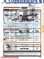
MODEL
XG-C455W
PG-C355W
Quick Start
DATA PROJECTOR
Setup
Connections
OPERATION MANUAL
Basic Operation Useful Features
Appendix
Downloaded From projector-manual.com Sharp Manuals
IMPORTANT
• For your assistance in reporting the loss or theft of your
Projector, please record the Model and Serial Numbers
located on the bottom of the projector and retain this
information.
• Before recycling the packaging, please ensure that you
have checked the contents of the carton thoroughly
against the list of “Supplied accessories” on page 10.
Model No.:
Serial No.:
SPECIAL NOTE FOR USERS IN THE U.K.
The mains lead of this product is fitted with a non-rewireable (moulded) plug incorporating a 10A fuse. Should
the fuse need to be replaced, a BSI or ASTA approved BS 1362 fuse marked
or
and of the same rating as
above, which is also indicated on the pin face of the plug, must be used.
Always refit the fuse cover after replacing the fuse. Never use the plug without the fuse cover fitted.
In the unlikely event of the socket outlet in your home not being compatible with the plug supplied, cut off the
mains plug and fit an appropriate type.
DANGER:
The fuse from the cut-off plug should be removed and the cut-off plug destroyed immediately and disposed of
in a safe manner.
Under no circumstances should the cut-off plug be inserted elsewhere into a 10A socket outlet, as a serious
electric shock may occur.
To fit an appropriate plug to the mains lead, follow the instructions below:
WARNING:
THIS APPARATUS MUST BE EARTHED.
IMPORTANT:
The wires in this mains lead are coloured in accordance with the following code:
Green-and-yellow : Earth / Blue : Neutral / Brown : Live
As the colours of the wires in the mains lead of this apparatus may not correspond with the coloured markings
identifying the terminals in your plug proceed as follows:
• The wire which is coloured green-and-yellow must be connected to the terminal in the plug which is marked by
the letter E or by the safety earth symbol
or coloured green or green-and-yellow.
• The wire which is coloured blue must be connected to the terminal which is marked with the letter N or coloured black.
• The wire which is coloured brown must be connected to the terminal which is marked with the letter L or coloured red.
IF YOU HAVE ANY DOUBT, CONSULT A QUALIFIED ELECTRICIAN.
The supplied CD-ROM contains operation instructions in English, German, French, Spanish, Italian, Dutch, Swedish,
Portuguese, Chinese and Korean. Carefully read through the operation instructions before operating the projector.
Die mitgelieferte CD-ROM enthält Bedienungsanleitungen in Englisch, Deutsch, Französisch, Spanisch, Italienisch,
Niederländisch, Schwedisch, Portugiesisch, Chinesisch und Koreanisch. Bitte lesen Sie die Bedienungsanleitung vor
der Verwendung des Projektors sorgfältig durch.
Le CD-ROM fourni contient les instructions de fonctionnement en anglais, allemand, français, espagnol, italien,
néerlandais, suédois, portugais, chinois et coréen. Veuillez lire attentivement ces instructions avant de faire
fonctionner le projecteur.
El CD-ROM suministrado contiene instrucciones de operación en inglés, alemán, francés, español, italiano,
holandés, sueco, portugués, chino y coreano. Lea cuidadosamente las instrucciones de operación antes de
utilizar el proyector.
Il CD-ROM in dotazione contiene istruzioni per l’uso in inglese, tedesco, francese, spagnolo, italiano,
olandese, svedese, portoghese, cinese e coreano. Leggere attentamente le istruzioni per l’uso prima di usare il
proiettore.
De meegeleverde CD-ROM bevat handleidingen in het Engels, Duits, Frans, Spaans, Italiaans, Nederlands,
Zweeds, Portugees, Chinees en Koreaans. Lees de handleiding zorgvuldig door voor u de projector in gebruik
neemt.
Den medföljande CD-ROM-skivan innehåller bruksanvisningar på engelska, tyska, franska, spanska, italienska,
holländska, svenska, portugisiska, kinesiska och koreanska. Läs noga igenom bruksanvisningen innan
projektorn tas i bruk.
O CD-ROM fornecido contém instruções de operação em Inglês, Alemão, Francês, Espanhol, Italiano,
Holandês, Sueco, Português, Chinês e Coreano. Leia cuidadosamente todas as instruções de operação antes
de operar o projetor.
Downloaded From projector-manual.com Sharp Manuals
Caution rega
IMPORTANT SAFEGUARDS
Introduction
Before using the projector, please read this operation manual carefully.
instructions
for later use.
the REGISTRATION
CARD packed with the projector.
Info
Introduction
CAUTION
Please read
all offor
these
instructions
you operate
this SHARP
productProjector,
and saveusing
these
There are two :important
reasons
prompt
warranty before
registration
of your new
Introduction
ENGLISH
1. Read Instruc
1. WARRANTY
Electrical
energy can perform many useful functions. This product has been engineered and manufactured to
to assure
that BUT
you IMPROPER
immediatelyUSE
receive
full benefit
of the parts,
service SHOCK
and labor
assureThis
yourispersonal
safety.
CAN the
RESULT
IN POTENTIAL
ELECTRICAL
OR
warranty applicable
purchase.
FIRE HAZARDS.
In order notto
to your
defeat
the safeguards incorporated in this product, observe the following basic
rules
its installation,
use and servicing.
2. for
CONSUMER
PRODUCT
SAFETY ACT
To ensure that you will promptly receive any safety
notification
of inspection, modification, or
13. Power-Cord
Protection
recall
that
may be required
to give
under the 1972
Consumer
Product
SafetysoAct,
All the
safety
andSHARP
operating instructions
should be read
before
Power-supply
cords should
be routed
that PLEASE
they are not
theREAD
product CAREFULLY
is operated.
likely to be walked
on or pinched by itemsU.S.A.
placedONLY
upon or
THE IMPORTANT “LIMITED WARRANTY”
CLAUSE.
against them, paying particular attention to cords at plugs,
2. Retain Instructions
convenience receptacles, and the point where they exit from
The safety and operating instructions should be retained for
WARNING:
theproduct.
beam of light, or view directly. Be especially
future reference. High brightness light source. Do
12not stare intothe
14.the
Lightning
3. Heed Warnings
careful that children do not stare directly into
beam of light.
For added protection for this product during a lightning storm,
or when it is left unattended and unused for long periods of
time, unplug it from the wall outlet and disconnect the cable
This
prevent
damagethis
to theproduct
product due
electric system.
shock,
dowillnot
expose
toto
lightning and power-line surges.
All warnings on the product and in the operating instructions
should be adhered to.
4. Follow Instructions
WARNING:
To reduce the risk of fire or
All operating and use instructions should be followed.
rain or moisture.
5. Cleaning
Unplug this product from the wall outlet before cleaning. Do
not use
liquid cleaners orequipment
aerosol cleaners. Use a damp cloth
Other
connected
See
forbottom
cleaning.of projector.
15. Overloading
Do not overload wall outlets, extension cords, or integral
convenience receptacles as this can result in a risk of fire or
electric shock.
The lightning flash with arrowhead symbol,
6. Attachments
16. Object and
Liquid
Entry triangle, is intended to
within
an equilateral
CAUTION
Do not use attachments not recommended by the product
Never push
objects
of any
kind
into this of
product
through
alert
the
user
to the
presence
uninsulated
manufacturer as
they
cause hazards.
RISK
OFmay
ELECTRIC
SHOCK.
openings“dangerous
as they may voltage”
touch dangerous
points or
within voltage
the product’s
DO NOT REMOVE SCREWS
7. Water and Moisture
short-out enclosure
parts that could
result
fire or electric
shock.
that may
be in
of asufficient
magnitude
SPECIFIED
USER
Do not use this EXCEPT
product near
water–for
example, near a bath
Never spill
of any kind
on the
toliquid
constitute
a risk
orproduct.
electric shock to
tub, wash bowl, kitchen
sink,
or
laundry
tub;
in
a
wet
SERVICE SCREW.
17. Servicing
persons.
basement; or near a swimming pool; and the like.
Do not attempt to service this product yourself as opening or
8. CAUTION:
Accessories
removing
covers
may exposepoint
you towithin
dangerous
voltageisor
TO REDUCE THE RISK OF ELECTRIC SHOCK,
The
exclamation
a triangle
Do not place this product on an unstable cart, stand, tripod,
other hazards.
Refer
all servicing
to the
qualified
service
intended
to
alert
the
user
to
presence
of
DO
NOT
REMOVE
COVER.
bracket, or table. The product may fall, causing serious injury
personnel.
important
operating
and
maintenance
NO
USER-SERVICEABLE
PARTS
EXCEPT
LAMP
UNIT.
to a child or adult, and serious damage to the product. Use
18. Damage(servicing)
Requiring Service
instructions in the literature
REFER
TObracket,
QUALIFIED
SERVICE
only with
a cart,SERVICING
stand, tripod,
or table
recommended
Unplug this
product from the
outlet and refer servicing
accompanying
thewall
product.
PERSONNEL.
by
the
manufacturer,
or
sold
with
the
product.
Any
mounting
to
qualified
service
personnel
under the following conditions:
Using
the
projector
in
other
countries
of the product should follow the manufacturer’s instructions,
a. When the power-supply cord or plug is damaged.
and should use a mounting accessory recommended by the
b. If liquid has been spilled, or objects have fallen into
manufacturer.
the product.
or modifications
to this toequipment
WARNING:
9. TransportationFCC Regulations state that any unauthorized changes
c. If the product
has been exposed
rain or water.not
expressly
approved
by the manufacturer could void
theproduct
user’s does
authority
to operate
this
d. If the
not operate
normally
by equipfollowing
A product and cart
combination
should
the operating instructions. Adjust only those controls
be moved with ment.
care. Quick stops,
U.S.A. ONLY
that are covered by the operating instructions,
as an
excessive force, and uneven surfaces
improper adjustment of other controls may result in
may cause the product and cart
damage and will often require extensive work by a
combination to overturn.
INFORMATION
qualified technician to restore the product to normal
10. Ventilation
This
equipment
andforfound
to comply with operation.
the limits for a Class A digital device,
Slots
and openingshas
in thebeen
cabinettested
are provided
ventilation
e. If the product
has been
dropped or damaged
in any
Temperature
monitor
pursuant
Part
15 of the
FCC
Rules.
are designed
to provide
reasonable
protection
to ensure to
reliable
operation
of function
the
product
and toThese
protect limits
it
way.
from
overheating,
and
these
openings
must
not
be
blocked
against harmful interference when the equipment is operated
in the
a commercial
environment.
Thisin
f. When
product exhibits
a distinct change
or covered. The
openings should
never
becan
blocked
by placing
equipment
generates,
uses,
and
radiate
radio frequency performance,
energy and,
not installed
and
used in
thisifindicates
a need for
service.
the product on a bed, sofa, rug, or other similar surface. This
accordance
the
operation
cause 19.
harmful
interference
Replacement
Parts to radio communications.
product shouldwith
not be
placed
in a built-inmanual,
installationmay
such as
Operation
a residential
area
cause
harmful
interference,
in which
When
replacement
parts
are required, ensure
that thecase
service
a bookcaseoforthis
rackequipment
unless proper in
ventilation
is provided
or is likely to
has used replacement parts specified by the
manufacturer’s
instructionstohave
been adhered
to.
thetheuser
will be required
correct
the interference
at histechnician
own expense.
U.S.A.
ONLY
manufacturer or have the same characteristics as the original
11. Power Sources
part. Unauthorized substitutions may result in fire, electric
This product should be operated only from the type of power
or other
source
indicated
on the marking
If you
are notwith
sure the
of device. shock,
The
enclosed
computer
cablelabel.
must
be used
The cable
is hazards.
provided to ensure that the device
20. Safety Check
the type of
power
supply
to your
home, consult your product
complies
with
FCC
Class
A verification.
Upon completion of any service or repairsU.S.A.
to this ONLY
product,
dealer or local power company. For products intended to
ask the service technician to perform safety checks to
operate from battery power, or other sources, refer to the
determine that the product is in proper operating condition.
operating instructions.
WARNING:
12. Grounding or Polarization
21. Wall or Ceiling Mounting
This
a Class
A product.
Inofathe
domestic
environment
this
maybe
cause
radio
interference
Thisisproduct
is provided
with one
following types
of
Thisproduct
product should
mounted
to a wall
or ceiling onlyinas
59
plugs.case
If the plug
fail to fit
the powerto
outlet,
which
the should
user may
beinto
required
take adequate measures.
recommended by the manufacturer.
please contact your electrician.
Do not defeat the safety purpose of the plug.
a. Two-wire type (mains) plug.
b. Three-wire grounding type (mains) plug with a
grounding terminal.
This plug will only fit into a grounding type power
outlet.
Downloaded From projector-manual.com Sharp Manuals
22. Heat
This product should be situated away from heat sources such
as radiators, heat registers, stoves, or other products
(including amplifiers) that produce heat.
-1
Image
Menu
Using
Helpful
Menu
Setting
Troubleshooting
Items
the
Projection
Functions
Items
up
Menu
theScreen
Projector
Set
duringmenu)
Netw
Installation
ork Environment
(ÒPRJ-ADJÓ (Òmenu)
NetworkÓ
Signal
Picture
Adjustment
Adjustment
(ÒS
(ÒPIG-ADJÓ
ictureÓ
Menu)
PRODUCT
DISPOSAL
menu)
This product utilizes tin-lead solder, and lamp containing a small amount of mercury.
Disposal of these materials may be regulated due to environmental considerations. For
Problem
Page
disposal
or recycling information, please contactCheck
your local authorities, the Electronics
Menu
operation
Page
The
follow
i
ng
show
s
the
items
that
can
be
set
in
the
projector.
•
Projector
power
cord
is
not
plugged
into
the
wall
outlet.
30 43
Industries
Alliance:
www.eiae.org,
the
lamp
recycling
organization
www.lamprecycle.org,
ÒProjecter adjustment (PRJ-ADJ)Ó menu
ONEKYST
'
"
Press
or
and
select
Sharp at 1-800-BE-SHARP.
U.S.A. ONLY
• Power to the external connected
devices is off.
—
buton 7
MOUSE/Adjustmen
Changing
the Password
4or
5
Setting/Changing
theInput
keycode
Selecting
the
Progressiv
Mode
Selecting
the
amiceRange
Checking
the
Signal
Maineu
SubMen Dyn
Selecting
the
TransmisÒB
rightÓ to adjust.
Note
3
butons(
' / " 34
/\ /| )
• The
selected input mode is wrong.
Auto Power Off
On
PRJ-ADJ
ÒPictureÓ
•sion
Themenu
selected
item (RS-232C)
is highlighted.
Speed
Off
An
optimum
picture
may
not
be
display
e
d
if
a
This
function
allow
s
y
o
u
to
check
the
current
Page
51
Page
51
Selectable
items
Description
•
The
AV
MUTE
function
is
working.
34
Caution Concerning Lamp Replacement • SetSelect
a level ÒP
soassw
as to
view
a clearer
picture. in| .
ordÓ
, then
press
Auto
Restart
On
Main Menu
Sub 61.
Menu
DVI-D-capable
dev
iceÕLamp”
s output
signal
type and the
put
signal
information.
3D
Useful
to
display
relatively
slowmoving
Select
Ò
S
y
s
tem
LockÓ
,
then
press
See
“Replacing
the
on
page
Make
sure
to
set
D
Ò
NRÓ
to
O
Ò
ffÓ
in
the
Make sure that Page
both51the projector
and
computerconnected to
Off
•
Cables
incorrectly
the
rear
panel
of
the
projector.
23-29
•
Standard
Picture
Picture
Mode
Progressive
images
suchtyp
asedrama
andmatch.
documentary
projectorÕ
s input
signal
do not
If this
ENTER
or | .
RETUNbuton
Presentation
arePage
set45for the System
same
baud rate.
follow
ingout.
cases:
Sound
On
•RangeÓ
Remote
batteries have
run
15
Page
45
more
clearly.
Moviefrom
should
occur,
swPage
itch
Ò51
Dynamiceither
. control
When
the
image
is
projected
the
top Display) panel.
Off
Game
This
SHARP
projector
uses
an
LCD
(Liquid
Crystal
•
When
This
very
the
sophisticated
image
is
blurry.
panel
contains 1,024,000
2D
Useful
to
display
fast-moving
images
such
*1
•
External
output
has
not
been
set
when
connecting
notebook
computer.
23
Selctab iems from the bottom
Descr ipt on
or
towards
at an angle,
sRGB
Contrast
-30 the
+30screen
On
Selectable
Description
pixels (xitems
RGB)Speaker
TFT’s
(Thin
Film
Transistors). As with any high
technology
electronicand
equipment
as large
• When
the contours
colors ofsuch
moving
im-.
Progressive
asPage
sports
and +30
action
films.
Off oidally.
Select
Ò
N
ex
t
Ó
,
then
press
ENTER
the
becomes
distorted
trapez
51
9Auto
6
0screen
bNo
ps image
Bright
-30
Tr sound
ansmi o pedi.s lwo blackand
60
• The
cover,
lampare
unit
cover
ordrag.
lamp
housing
cover
is not
TVs, and
video
video
cameras,
there
certain
acceptable
tolerances
that in
the
equipment
must
When
the
levels
of filter
the
image
show
Enter
the
passw
o
rd
O
Ò
ld
Passpicture
nosystems
ages
*2
The
function
for
correcting
trapez
o
idal
distortion
FAO
.sraep edocyk •eht gniret rof nercs ehT
Audio
Color Out
-30appear
+30
installed
correctly.
conform
to. does
Standard
banding
or
faded,
select
the item
not
start.
4
0 bps projector
VAO
' (Key
o
w On-screen
rdÓTVusing
, "stone
, | Correction
and \ are
, mode)
then
• When
broadcasts
with
weak
signals
prois38or
called
Keystone
Correction.
*2
"which
Display
51-30 +30pixels
TintPageinactive
This unit has some
within
acceptable
tolerances
mayisresult
in inactive
dotsthe
on the picture
Enhanced
that
results
in
the
best
picture
quality.
(In
•
If
the
connected
DVI
digital
equipment
turned
on
before
24
o
r
p
e
h
t
s
u
j
d
a
T
This
projector
is
equipped
i
w
th
an
A
Ò
uto
V-Key
Monitor
Out
Enable
jected.
*2
11520
b
p
s
0
press
ENTER
.
Tr
a
n
s
m
i
o
s
p
e
d
i
s
a
r
p
d
.
Sharp
-30
+30
screen.
This will
not
affect
the
picture
quality
or
the
life
expectancy
of
the
unit.
H&V
KEYSTONE
H:
0
V:
0
Note
most
circumstances,
S
“ tandard”
should
Disable
“DVI-D”
input
mode is selectedPress
on the the
projector,
the image
Page
51 that automatically
4 buttons
on may
the remote
stone CorrectionÓ
function
corRed selected.)
-30
+30
elihwgamdtcj trapez
be
ENDbe displayed at all. ADJUST
Enable
LAN/RS232C
rects
any
idal distortion
within
pro- toproperly or may
not
bethe
projected
not
Ensure
• When
the oimage
is
blurred
or
noisy,
switch
control or on the projector to enter
Disable
Blue
Page
51-30 +30
Info
®
jected
image.
The
correction
is®made
automatically
that
the appropriate
input
mode
has
been
• the
Microsoft
and
Windows
are
registered
trademarks
of Microsoft
Corporation
United
and/or
optimal
mode.
t
i
g
n
h
c
a
w
TESTPATTERN
RESET
Enter
the selected
passw
othe
rdon
inthe
ÒN
ew
PassPage
45
the
preset
key
cinode
in
ÒO
ldStates
CodeÓ
.
N
o
t
e
9600
bps
RS-232C
prov
ded the
ev rtical
incline orinputs,
decline
is iwbefore
thin
function is equipment.
available for all signals with
projector
you turn on• This
the connected
38400 bps
• iother
When
using
progressive
inputs
are
dicountries.
Page
52
'
"
|
\
,
,
and
,
then
w
o
rdÓ
using
CLR Temp
5500K bps
•
W
h
e
n
s
t
i
g
k
y
c
o
d
e
f
r
t
h
i
s
m
e
,
±12• Refr to degrees.
115200
Note
the ÒSETUP MANU LÓ contai ed on
S-VIDEO.
6500K
rectly
displayed
Progressive”
and connected
Cables
incorrectly
to pres theorrear
of the
projector.
23-29
is a ENTR registered
of International
BusinessVIDEO
Machines
Corporation
the United States.
Page
45 that
1• PC/AT
Setting
a®so
Passw
o“2•Drd
Press
. trademark
7500K
"ENTER
ontheprjcof urtimes. panel
press
. infor
Normal
Fan Mode
V
C
n
o
s
y
K
l
a
c
i
t
r
e
the suplied CD-ROM for RS-2D32C
Specif a- ®
•
This
function
is available
480I , 480P, 576I
•
The
Dynamic
Range
can
be
selected
only
when
8500K
“
3
Progressive”
cannot
be
selected.
High of Adobe
• Adobe
Reader
isitem
a trademark
Systems
Incorporated.
• “Bright”
is
set
to
minimum
position.
45
Page 52
•
The
selected
(e.g.
“
B
right”
)
is
dis9300K
(Adjustmenwih
' /" )
t iu
onsadCm Setings. VI-D”
and 576P
signals with COMPUTER1/2
or DVI.
If•yo“Macintosh
do not
wa®nt
others
to change
the setting
D
input
mode
is selected.
10500K
System
Lock
Old
Code
is
a
registered
trademark
Apple
Computer,
Inc.
in
the
United
States
and/or
other
countries.
played
by
itself
at
the
bottom
of
the
•
Depending
on
the
computer
you
are
using,
an
image
may
not
—
to the cosmputerÕ opeartin manul orf ÒNetworkÓProgressive
New
for•• eRrf the
menu,
oCode
rd.
Pages 52set
and a
53*3passw
3D Progressive
Enter
the same
passw
ord and/or
again
in
Reconfirm
•.etar dub s Õretupmoc h gnites rof PJLink
is
a
registered
trademark
or
an
application
trademark
in
Japan,
the
United
States
other
screen.
be
projected
unless
the
signal
output
setting
of
the
computer
is
2D Progressive
tsniocu Selecting
Page 46 the Film Mode
5 countries/regions.
switched
to
the
external
output.
Refer
to
the
computer’s
' or*3 " , the following
• When pressing
' , " , | (MNR)
and \ ,
econfirmÓNoise
using Reduction
All Reset
7 ÒRMosquito
Film Mode
Auto
Password
Sound
isaheard
but
no
6•Setting
Setting
the
Sy
s
tem
Page
53or
manual
for how
to
switch
its
signal ENTER
output
settings.
item
(“R
ed”
after
“product
BVideo
right”)operation
will
be
disOff
Allfunction
other
company
names
are
trademarks
or
registered
trademarks
of
their
respective
compathen
press
.
This
prov
i
des
high-quality
play
b
ack
of
Page
46
picture
appears.
Lamp
Timer
(Life)
The so-called Mosquito Noise (flickering) can be
played.
images
originally
projected
at
fps,
such
as
nies.
DNR
Off24
Page
53
The
video
input
sy
s
tem
mode
is
factory
preset
Press
ENTER.
Fan Mode
Setting
Level 1
reduced. set.
• Image
adjustments
45
46 picture
movÒAies
on
Level
2 the con-|
to
utoÓ
; howDVDs.
ever,ÒPaPage
clear
from
Select
assw
ordÓ, then
press
. are incorrectly
Level 3
This
function
changes
the
fan
rotation
speed.
(Video,
S-Video
Input
only)
When
o
y
u
a
w
nt
to
make
fine
adjustments
after
the
Selectable The
items
displayed byDescription
itself
nected
isual equipment
may for
notthe
beEuropean
re• audio-v
Note
N o t e item
Selectable
items
Description
Authorized
representative
responsible
Union Community
Market
MNR
Off
ÒN
etw
odepending
rkÓsmenu
Auto
V-Key
tone
Correction
function
has1 been
acti• Video
input
system is incorrectly
set. MNR does not function.
48
Off
Level
ceiv
ed,
onare
the
Video
signal
difference.
Films
detected
automatically.
Sa
ev Auto
lctab iemsted,
Page
46
D
e
s
c
r
i
p
t
o
n
•DVI-D
If you input a wrong keycod , the curso
2
ENTER
again(COMPUTER/COMPONENT
toLevel
return
or h
w •enPress
o
y u aw nt
to make
corrections
iw thoutto the
Level
1-3
Sets
the
MNR
level
for
viewing
a
1,
2,
only)
•
Off
Films
are
not
detected.
In
that
case,
sw
i
tch
the
Video
signal.
Level
3
ELECTRONICS
(Europe) GmbH
Normal SHARP
Suitlaoebrfn mlevniro t.s sscreen.
Main the
Menu
r e t u fn h o is p Ò O C l d e Ó .
using
Auto
V-Key
tone Correction
function,
previous
clearer picture.
• Input
signaloy utype (RGB/Component)
is incorrectly
set.
47
E.U. ONLY
Eco+Quiet
Mode Hamburg
On
Sonninstraße
3,
High Network
Selct hiswenuigtheprojct a D-20097
Old the
Password
Password
•
e
h
Tt sd o rc py k i 4
" snot ub eh
can
make
corrections
manually
using
follow
i
ng
Off
Selectable
items
Color is faded
or
poor.
New Password
Page
46
ENTER
altiudesofaprximtely1,50metrs
Page 54
eht s erp uo y nehW . rotcej p
" b ruo f not u
procedure.
Reconfirm
Auto Page 54
HorizntalKeysCc
Info
• Adjust the focus.
33
(4,90 fe t) or m e.
Note PALReset
.
s
r
a
e
p
i
d
n
e
r
c
s
t
u
p
n
i
d
r
o
c
y
e
k
h
t
,
s
e
m
i
t
Client
On
Page
45
(Adjustmenwih function is available\ for
/ | all
) signals
| to adjust
Press \DHCP
or
the
item
RETURN
•
This
with
Off
•inputs,
The projection
distance exceeds the focus range.
19
rotainfheÒHgÓ,sMdFW • When using
SECAM
Page
55
progressive
“Film Mode”
Press
*1 on the remote
selected.
VIDEO
or
S-VIDEO.
*1
Item
when
inputting
RGB
signal
through
COMPUTER/COMPONENT
1,
2
or
DVI-D
TCP/IP
IP
Address
*NTSC4.43
. anoise,bcmdlurthfp cannot be selected.
• There
is fog on the lens. If the projector is carried from a cold
—
Subnet Mask
• The
is stored.
*2 Items
whenadjustment
inputting
Component
signalCorrecthrough COMPUTER/COMPONENT
1 oris2,
or
when selecting
VIDEO
or576I
•ifThis
function
for on
480Ithe
, 480P,
control
toPage
enter
the
Key
sroom
tone
55
Press
the
4available
buttons
remote
Gateway
into
a
warm
room,
or
it
is
suddenly
heated,
•S-VIDEO
The “FilmNTSC3.58
Mode”
function
does
not
work
when
*2
MAC Address
If and
you
forget
the
password
576P
signals
with
COMPUTER1/2
DVI.
PAL-M
mode.
condensation
may
form
onI , the
surface
oforthe
lens
and
the
control
on
the
projector
toorenter
Dtion
Progressive”
selected
inadjusted
“Pfirst
rogressive
Page
55Mode”
*3 “P“2
rogressive”
and
“Flimis
can be
only when
480 If
576I
, 1035Ithe
or 1080I
signal
is input.the following
'
"
Press
or
to
set
the
digit
in
PAL-N
y
o
u
forget
passw
o
rd,
perform
Lock Function
*2
•Sys
KEYSTONE
image will become blurred. Please
set up
projector
least.
Mode”
. tem
Projector
the new
keycthe
ode
in ÒNew at
CodeÓ
1
1
2
2
3
3
4
1
4
1
4
2
PAL -60
| . it is to be procedure
N
Ò ew Passw
ordÓ, then press
to delete it, then
set form,
a new password.
one hour before
used. If condensation
should
Page 55
8 theEco+Quiet
This
function
ents
unauthoriz
ed in
use
of
the
Mode
Setting
Picture
is prev
blurred;
* When
reproducing
NTSC
signals
PAL
videocord from
remove
the
power
wall outlet
and wait
for it to
On the projector,
press
projector.
Once
this
function
is
activ
a
ted,
users
noise
appears.
*1
Adjustable
only
when
DHCP
Client
is
set
to
“
O
ff”
clear.
Note
6equipment.
Reducing
Image
Noise
Enter
remaining
3 digits,
Press
' correct
or
" keyto
paralleliz
e (DNR)
the
must
enter
thethe
code
each
time
thethen
pro*2 Display
only
(Computer
Input
only)
•
Y
o
u
c
a
n
o
t
u
s
e
t
h
e
o
l
w
f
i
n
g
u
t
b
o
n
s
o
r
f
Fan
Selectable
ENTER
. sides,
jector
is
turned
on.
We suggest
youor
record
thehigh
left
and
right
press
Videopress
digital
noise
reduction
prov
ides
Lamp47
life
Brightness
•(DNR)
Perform
“SIG-ADJ”
Adjustments.
Adjustment)
ycode:
STANDBY/ON,
SoundON, STANDBY,
itemsek (“Clock”
M
E
N
U
.
•
\
keycode
in
a
safe
place
where
only
authoNote
qualityPress
images
w
i
th
minimal
dot
craw
l
and
cross
\ or | to paralleliz•ePerform
the upper
47
“SIG-ADJ” Adjustments. ENTER,
(“Phase” L-CLICK,
Adjustment)
R-CLICK/RETURN,
• Thehave
menuaccess.
screen will disappear.
rized
users
color
noise.
• The
Video
canof
only
set may
in VIDEO
or depending
ECO+QUIET
and
TIMER
• be
Noise
appear
onMENU,
the computer.
—
Approx.
80%
Approx.
Low BREAK
and
lowesignal
r sides
the
projected
• On
ENTER
S-VIDEO
mode.
System
function
recognizes 3,000
each
Selectable
itemsthe same passw
Description
Enter
ord inincorrectly connected to• the
• Cables
rearlock
panel
of the projector.
23-29
image.
• When
System”
is
to “Auto”, you may
Info “VideoDNR
button on the remote control or hours
on the
Off
notset
function.
53 RETURN
Ò •receive
econfirmÓ
,does
then
press
ENTER
• due
Volume
is setdifferto .minimum.
• projector
notR
a clear
picture
to signal
as an indiviNormal
dual button, Approx.
even34
if
Off
100%
Level
1–
3
Sets
the
DNR
level.
• ences.
fI uoy esol ro tegrof ruoy ,edocy k tca no ruoy •
' " • switch
\ |to
•
When
thethe
projector
to an
external
device
and name.
the 2,000
Should this occur,
video is connected
they
share
the same
button
If o
y u
-reS o laD rtcejP dohuziAraSptsesystem
n
notbuttons
output on
even
you
hours
of the source signal.volume is set to minimum, the sound
theif projector
in set• usedisthe
vice Centr (se page Note
68). enEv if the product turn up the volume of the externalting
device.
o
y ur keycode, the keycode cannot
war nty is valid, the keycod res t wil incur a
Picture
appearsdobut
be “Acanceled
the remote
set to “Off”.
• Menu
buttons
notno
function
while theis
projector
is operating• the
uto Sync”,iw th
“Break
Timer”, “Fcontrol.
REEZE”,51
Press
.• “Speaker”
.egrahc sound
is
heard.
Note
or “A
• V MUTE” functions.
• Data image is not
• Make the necessary adjustments
of each
itemECO+QUIET
in the “SIG-ADJ”
47
• You can
also use
on the remote
menu.
• centered.
KEYSTONE
control or on the projector to switch the Eco+Quiet
(See
pagethe
35.)output resolution
• Depending on the computerMode.
you are
using,
—
3
2
5
4
3
signal may be different from the one you have set. For details,
refer to the operation manual of the computer.
-2 From projector-manual.com Sharp Manuals
-32
-40
-42
-44
-46
-48
-52
-54
-66
Downloaded
Introduction
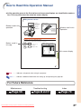
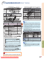
How to Read this Operation Manual
• In this operation manual, the illustrations and on-screen displays are simplified for explanation. This may differ from the actual on-screen display.
Using the Menu Screen
Adjustment
buttons ('/"/\/|)
ENTER button
Buttons used in this
operation
MOUSE/Adjustment
buttons ('/"/\/|)
ENTER
button
MENU button
MENU button
RETURN button
Buttons used in this
operation
RETURN button
• Press RETURN to
return to previous
screen when the
menu is displayed
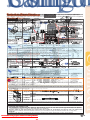
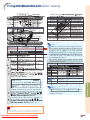
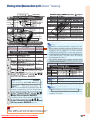
Menu Selections (Adjustments)
Example: Adjusting “Bright”.
• This operation can also be performed by using the buttons on the projector.
Button used in
this step
1
Press MENU.
• The “Picture” menu screen for the selected input mode is displayed.
2
Press | or \ and select “Picture” to adjust.
Example: “Picture” screen menu
Menu item
Picture
SIG
SCR
PRJ
Net.
Standard
0
0
0
0
0
0
0
SEL./ADJ.
RETURN
On-screen display
7500K
3D Progressive
Auto
Off
Off
Off
Useful Features
Picture Mode
Contrast
Bright
Color
Tint
Sharp
Red
Blue
CLR Temp
Progressive
Film Mode
DNR
MNR
Eco+Quiet Mode
Reset
ENTER
END
-43
Info ...........Indicates safeguards when using the projector.
Note ........Indicates additional information for setting up and operating the projector.
For Future Reference
Maintenance
Troubleshooting
Page 56
Downloaded From projector-manual.com Sharp Manuals
Pages 66 and 67
Index
Page 70
-3
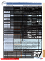
Contents
Preparing
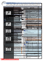
Introduction
Useful Features
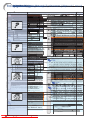
How to Read this Operation Manual ............. 3
Contents .......................................................... 4
How to Access the PDF Operation Manuals .... 6
IMPORTANT SAFEGUARDS .......................... 7
Accessories .................................................. 10
Part Names and Functions .......................... 12
Using the Remote Control ........................... 15
Menu Items ................................................... 40
Using the Menu Screen ............................... 43
Usable Range .................................................... 15
Inserting the Batteries ....................................... 15
Quick Start
Quick Start .................................................... 16
Setup
Setting Up the Projector .............................. 18
Setting Up the Projector .................................... 18
Projection (PRJ) Mode ....................................... 19
Connections
Samples of Cables for Connection ............. 21
Connecting to a Computer .......................... 23
Connecting to Video Equipment ................. 25
Controlling the Projector by a Computer ... 27
Connecting to a Monitor with RGB
Input Terminal ......................................... 28
Connecting to an Amplifier or Other
Audio Equipment .................................... 29
Using
Basic Operation
Turning the Projector On/Off ....................... 30
Connecting the Power Cord .............................. 30
Turning the Projector On .................................... 30
Turning the Power Off (Putting the Projector into
Standby Mode) ............................................ 30
Image Projection .......................................... 31
Using the Adjustment Feet ................................ 31
Correcting Trapezoidal Distortion ...................... 32
Adjusting the Lens ............................................. 33
Switching the Input Mode .................................. 34
Adjusting the Volume ......................................... 34
Displaying the Black Screen and Turning off
the Sound Temporarily ................................ 34
Displaying and Setting the Break Timer ............ 35
Switching the Eco+Quiet Mode ......................... 35
Auto Sync (Auto Sync Adjustment) ................... 35
Freezing a Moving Image .................................. 35
Selecting the Picture Mode ............................... 36
Displaying an Enlarged Portion of an Image .... 36
Resize Mode ...................................................... 37
Using the Remote Control as the Wireless
Computer Mouse ........................................ 39
-4 From projector-manual.com Sharp Manuals
Downloaded
Menu Selections (Adjustments) ......................... 43
Picture Adjustment (“Picture” menu) ........ 45
Selecting the Picture Mode ............................... 45
Adjusting the Image .......................................... 45
Adjusting the Color Temperature ....................... 45
Selecting the Progressive Mode ........................ 46
Selecting the Film Mode .................................... 46
Reducing Image Noise (DNR) ........................... 46
Mosquito Noise Reduction (MNR) ..................... 46
Eco+Quiet Mode Setting ................................... 46
Signal Adjustment (“SIG-ADJ” Menu) ........ 47
Adjusting the Computer Image ......................... 47
Resolution Setting .............................................. 47
Auto Sync Adjustment ....................................... 47
Signal Type Setting ............................................ 47
Selecting the Dynamic Range ........................... 48
Setting the Video System ................................... 48
Checking the Input Signal ................................. 48
Screen Adjustment (“SCR-ADJ” Menu) ..... 49
Setting the Resize Mode ................................... 49
Adjusting the Image Position ............................. 49
Keystone Correction .......................................... 49
Setting the On-screen Display ........................... 50
Selecting a Startup and Background Image ..... 50
Selecting the Menu Screen Position .................. 50
Reversing/Inverting Projected Images .............. 50
Selecting the On-screen Display Language ..... 50
Helpful Functions Set during Installation
(“PRJ-ADJ” menu) ................................. 51
Auto Power Off Function .................................... 51
Auto Restart Function ........................................ 51
Setting the Confirmation Sound
(System Sound) ........................................... 51
Speaker Setting ................................................. 51
Audio Output Type Setting ................................ 51
Monitor Output ................................................... 51
LAN/RS232C ..................................................... 51
Selecting the Transmission Speed (RS-232C) .. 52
Fan Mode Setting .............................................. 52
System Lock Function ....................................... 52
Keylock Function ............................................... 53
Returning to the Default Settings ....................... 53
Checking the Lamp Life Status ......................... 53
Setting up the Projector Network
Environment (“Network” menu) ............ 54
Setting a Password ............................................ 54
DHCP Client Setting .......................................... 55
TCP/IP Setting ................................................... 55
Confirming the Projector Information ................. 55
Introduction
Reference
Appendix
Maintenance ................................................. 56
Replacing the Air Filter ................................ 57
Replacing the Air Filter ...................................... 57
Maintenance Indicators ............................... 59
Regarding the Lamp .................................... 61
Lamp ................................................................. 61
Caution Concerning the Lamp .......................... 61
Replacing the Lamp .......................................... 61
Removing and Installing the Lamp Unit ............ 62
Resetting the Lamp Timer ................................. 63
Storing the Projector ................................... 64
How to Use the Storage Case ........................... 64
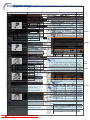
Computer Compatibility Chart .................... 65
Troubleshooting ........................................... 66
For SHARP Assistance ................................ 68
Specifications ............................................... 69
Index .............................................................. 70
SETUP MANUAL
Refer to the “SETUP MANUAL”
contained on the supplied CDROM for details.
Setting up the Screen .................................... 2
Screen Size and Projection Distance ........... 3
Changing the Lens ......................................... 9
Connecting Pin Assignments ..................... 11
RS-232C Specifications and Commands ... 13
Setting up the Projector Network
Environment ............................................ 18
Controlling the Projector via LAN .............. 24
Setting up the Projector Using
RS-232C or Telnet ................................... 29
Resetting the Lamp Timer
of the Projector via LAN ......................... 39
Troubleshooting ........................................... 41
Dimensions ................................................... 44
Downloaded From projector-manual.com Sharp Manuals
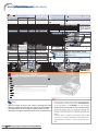
-5
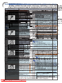
Accesso
Quick
S
When connec
T
e
rm
proj
AUD
How
IMPORTANT
Part
Part
Samples
Connecting
Controlling
Names
Names
toofAccess
the
Cables
to
and
SAFEGUARDS
Video
aProjector
Computer
Functions
and
forEquipment
Connection
the
Functions
by PDF
a Computer
Operation
Manuals
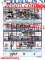
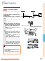
This section shows the basic operation (projector connecting with the computer). For details, see the page
Supplied
PDF operation
Numbers
When
connecting
accessories
in
manuals
refer
to Terminal
the
to
the
in
LAN
main
terminal
pages
languages
using
in thisa operation
are
LANincluded
cablemanual
in the
where
CD-ROM,
the topic
so that
is explained.
you can
on several
described
below
for
each
step.
Equipment
Cable
connectedTo
equipment
work with the projector.
utilize these manuals, you need to install Adobe® Reader ® on your
The projector
employs
the 30
DVI digital®input terminal for direct input
of Digital
Video signals from a
STANDBY
button
R/C JACK
TX/RXWIRED
LED
(yellow)
computer
(Windows® or Macintosh
). stereo minijack to RCA audio
Audio-visual
ø3.5 mm
cable
For putting the projector into
Illuminates
when transmitting/receiving
data.
For controlling
the projector by
connecting
computer.
LINK LED
audio output
terminal
equipment
(for
standby
mode.
In
this To
section,
connection
the (commercially
projector
the computer is explained
using
one
example.
the (green)
remote
control
toCOMPUTER/
the projector.
Caution
concerning
theoflamp
unit andavailable)
Audio
Illuminates when linked.
®
®
about
placing
the
projector
in a
COMPONENT
1, 2, DVI-D)
Please
download
Adobe
Reader
(http://www.adobe.com).
Potential
hazard
of glass
par- from the InternetWarning
To
input terminal
output
To S-video
output
terminal
ON button
30S-VIDEO
button
32
Top
ViewKEYSTONE
7
STANDBY
high
position
ticles
lamp the
ruptures.
In case
For turning the power on.
Computer
HUB
terminal
For if
entering
Keystone
3 7 STANDBY/ON button
Two R-6 batteries
To AUDIO inputbutton
When placing the projector
in terminal
a high posiof orlamp rupture,
your
Accessing
the
PDFcontact
Manuals
Correction
mode.
(“AA”
size,
UM/SUM-3,
RGB
cable
DIN-D-sub
RS-232C
MENU
button
43
nearest
Sharp
Authorized
Protion,
make
certain
it
is
carefully
secured
to
6 INPUT buttons For Macintosh*®:To ensure
safety, do
notbutton
connect
Computer
For
Windows®ENTER
:
For displaying
and the
3adjustment
ON
HP-7
or
similar)
(10'
(3.0
m))
adaptor
button
44
jector
Dealer
or Service
Cen-Connect with the cable adaptor,
Remote
control
Terminal
etc.
avoid
personal
injury
caused
by
the
projecLAN terminal
with
any cables
setting
screens.
57
1
Insert
theitems
CD-ROM
1 Insert the CD-ROM
in(5
the
drive.such
setting
selectedin
orthe CD-ROM drive.
/CD-ROM
64" (15 cm))
terFor
for
replacement.
6 ENTER button <QCNWGA045WJPZ>
for using
<RRMCGA623WJSA>
torDouble
falling click
down.
asthe
a telephone
line
that may cause
adjusted
onthe
the“My
menu.
2
Double
click
Computer”
icon.
2
“CD-ROM”
icon.
MOUSE/Adjustment
buttons
See “Regarding the Lamp”
<QCNWGA091WJPZ>
Video Equipment
Cable adaptor 39·43
the on
excessive
voltage.
('/"/\/|)
3
Double
“CD-ROM”
drive.
When you
want to
view the operation manual
Power
cord*click the
page
61.
LAN
cable
(Category
5 type, commercially available) 3
(commercially
available)
dedicated
moving the computer
cursor
Do
subject theFor
projector
hard
im(2) operation manual
(3)Tonot
4(1)When you
want button
to view
the
1) Double
“MANUALS”to
folder.
LAN
terminal click the(4)
L-CLICK
39
cable
when with the USB connection
pact
and/or
vibration.
Dedicated
For the
Left click click
when with
2) Double click the
language
of
the
1) Double
the the
“MANUALS”
folder. cable
To(name
DVI-D
input
terminal
(using
a USB cable
or the
optional
To AUDIO input terminal
USB connection
(using a USB
Take care with the want
lensto
soview.
as not to hit or
Caution
concerning
setup(name
of theofproreceiver).
(for DVI-D) folder) that you remote
2)Note
Double
click the the
language
the
ø3.5 mm stereo minijack to RCA audio
cable or the optional
jector folder)
To DVI digital
Forofselecting
and adjusting ondamage
theavailable)
surface
the
3) Double
click
the pdf
file lens.
to access the prothat
want
to view.
cable
'you
"
\hub,
| use
remote
receiver).
5
Zoom
knob
output
terminal
•For
When
connecting
to
straight-through
Category
5 (commercially
(CAT.5)
type cable
(commercially
available).
minimal
servicing
to maintain
high
Foritems.
Australia,
New
For
U.K.,
Hong
Kongscreen
Europe,S-video
except
U.K.
For
U.S., RCA
Canada,
etc.and For
cable
(commercially
available)
audio cable
jectortype
manuals.
3) Double
click
the
pdf
file touse
access
the pro(Enlarge/Reduce)
36
•MAGNIFY
When
connecting
to
computer,
cross-over
Category
5
(CAT.5)
cable
(commercially
available).
(commercially
available)
image
quality,
SHARP
recommends
that
this
Zealand
and
Oceania
and
Singapore
(6' (1.8
m))
(6' (1.8 m)) buttons
R-CLICK/RETURN
button
Rest
your
eyes
occasionally.
39·43
RCA
available)
AUDIO
jectorbe
manuals.
you want to
view
the click
setup
manual
projector
installed
in an area
freeaudio
fromcable
hu- 5(commercially
Focus Continuously
ringWhen
For (6'
thethe
Rightscreen
whenfor
withlong
the
(1.8
m))
(6'
(1.8 m))
<QACCVA011WJPZ>
<QACCDA007WJPZ>
For enlarging/reducing
part of Audio
the
watching
(for
VIDEO,
S-VIDEO)
1)
Double
click
the
“SETUP”
folder.
When
you
want
to
view
the
setup
manual
midity, dust and cigarette
smoke. When the
USB connection (using a USB
image.
DVI
Digital cable
6 COMPUTER
1
<QACCLA018WJPZ>
<QACCBA036WJPZ>
hours
will cause
eye
strain.
Take
regular
cable
or
the optional
remote
receiver).
projector
is subjectedoutput
to these environments,
2) Double
click the
language
(name
of the
1)audio
Double
(commercially
available)
To
outputclick the “SETUP” folder.
button
PAGE
Up/Down
buttons
terminal
For
returning
to
the
previous
39
breaks
to
rest
your
eyes.
and
lens
must
be cleaned
more
terminal
*the
Use
the
power
cord
that
corresponds
to the
wall
folder) that you display.
want to view.
2)vents
Double
click
the
language
(name
of
theoutlet in your country.
Same as the [Page Down] and
often.
As
long
as
the
projector
is
regularly
3)
Double
click
the
pdf file to access the setup
folder)
that
you
want
to
view.
[Page Up] keys on a computer
cleaned,
use with
in these
environments
will not
Volumeextremes
buttons
locations
of tem34 with
Terminal
Connect
the cableAvoid
adaptor,manual.
etc.
keyboard,
when
43)Tilt
dial
Double
click the
theUSB
pdf
file to access
thewith
setup
For adjusting the speaker sound
4 unit.
Height Adjustment
buttons
reduce(using
the aoverall
operation
connection
USB cable
or using life of the
for
perature.
manual.
Internal
cleaning
should
be performed
the optional
remote receiver).
* ø3.5 mm stereo
oradaptor
mono audio cable level.
theonly
operating
temperature
of ofthe
projector
You can display computer images
on both the projector
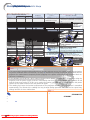
and Cable
aThe
separate
monitor
RGB
cables.
(commercially
available
or available
as using two sets
When connec
Connecting to a Monitor with RGB Input Terminal
by a Sharp Authorized
Projector Dealer orSharp service
(commercially
available)
dedicated
QCNWGA038WJPZ)
AV MUTE
ispart
from
41°F
to
(+5°Cbutton
to +35°C).
3495°F
BREAK
TIMER button 35
Service
Center.
cable
For temporarily
displaying
the black
ForTodisplaying
the
break
timer.
The
storage
temperature
of
the
projector
is
output terminal
Dedicated cable
Frontaudio
View
screen and turning off the sound.
from
–4°F
to
140°F
(–20°C
to
+60°C).
Do not
the projector Lens
in places
exStorage case
Lensset
cap up
(attached)
cap strap
AUTO
SYNC
button
To
video
output
terminal
35audio cable, theComputer
* When using
the
ø3.5
mm mono
volume level willSupplied
be half of when using the ø3.5 mm stereo
cable.
Monitor
RGBaudio
cable
FREEZE
button
35
posed
sunlight
or <UBNDTA017WJZZ>
bright light.
RCA audio
Tocable
VIDEO
input terminal
For
automatically
adjusting
images
<GCASNA020WJSA>
accessory
Infoto direct
<PCAPHA026WJSA>
For freezing
images.
(commercially
available)
Position
the toscreen
so that it is not in direct
To AUDIOand
input terminal
when
connected
a computer.
Do not block
the
intake
exhaust
•sunlight
If the desired
pdf light.
file cannot
opened
by double
or room
Light be
falling
directly
on clicking the mouse, start Adobe® Reader ® first, then
• Operation manual (this manual <TINS-D563WJZZ> vents.
and CD-ROM <UDSKAA102WJZZ>)
37 7 RESIZE button
Monitor
RGB
cable
(supplied
or commercially available)
MONITOR OUTPUT
specify
the desired
fileout
using
“File”,
“Open”
menu.
PICTURE
MODE
button
the
screen
washes
thethecolors,
making
36
Allow
at
least
7 /For
8 inches
space
switching(20
the cm)
screenofsize
For
switching
the picture
mode.
RGB
viewing
difficult.
Close
the curtains and dim
Page
18
(NORMAL,
STRETCH,
etc.).
between
the
exhaust
vent
and
the
nearest
inputup the screen in a
the lights when setting
Video Equipment
To COMPUTER/
wall
or
obstruction.
35 ECO+QUIET button
Note
INPUTroom.
buttons
34
terminal
sunny
or bright
COMPONENT 1
For switching to the respective
• Codes in “< >” are Replacement parts codes.
inputEnsure
terminal
ForTolowering
noise
the cooling
MONITOR
OUT
terminal
that the intake
vent the
and
theofexhaust
fan and extending the lamp life.
modes.
output vent are not obstructed.
The
projectorinput
may
be safely
tilted
toTo
aRGB
Amplifier
ø3.5
mm stereo
minijack to RCA audio cable
AUDIO
To RGB input terminal
terminal
Optional
accessories
maximum
angle of 9 degrees.
obstructed,
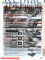
a pro(commercially available) If the cooling fan becomes(MONITOR
OUT)
Audio
Placement should be
within ±9 degrees of
tection circuit will automatically put the proLamp unit
AN-C430LP
horizontal.
When the signals
fromcable
theinput
remote control
cannot
reached
dueavailable)
to the
positioning
projector,
use a
RCA audio
Composite
video be
cable
(commercially
jector
into
standby
modeoftothe
prevent
overheat
Ceiling-mount adaptor
AN-60KT
terminal
(commercially
ø3.5 mm minijack
cable available)
to connect the remote control
to the
projector.
Now
you not
can indicate
control the
projector
damage.
does
a malfuncAN-XGCM55
(forThis
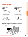
U.S.A.
only)
withUniversal
the remote
control.
bracket
AN-JT200
only)
tion (for
(seeU.S.A.
pages
59 and 60). Remove the pro-
Ceiling-mount unit
Projector
(Rear
view) connecting
When
AN-TK201
<for
AN-60KT>
jector
power
cordcontrol
from the wall outlet and wait
Remote
Topages
WIRED
WIRED than the computer,
equipmentTo other
seeleast
25,
28 andPlace
29. the projector where
AN-TK202
<for10
AN-60KT>
at
minutes.
REMOTE terminal
R/C JACK
AN-EP101B
<for AN-XGCM55
AN-JT200>
23, 30
Attaching the lens cap
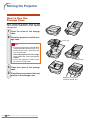
the intake
and exhaust and
vents
are notPages
blocked,
(for
U.S.A.
only)
After putting the lens cap strap on the lens
RGB cable
plug the power cord back in and turn on the
Remote
receiver
AN-MR2
Note
cap,
pass
thethe
other
end of the
strap
When
using
projector
inø3.5
high-altitude
mm minijack cable (commercially available or
projector. This will return the projector to the
available
asm))
Sharp
partAN-C3CP2
QCNWGA038WJPZ)
through
the
the
front
side
of
the
RGB
cable
(commercially
available)
3 RCA
to hole
15-pin
D-sub
cable
(10'
(3.0with
• When
you
connect
video
equipment
a service
21-pin
RGB
output (Euro-scart)On
to the
the remote
projector,
use a comareas
such
as on
mountains
(at
altitudes
ofOn
the
projector
control
operating
condition.
projector,
to the
lens,meters
as
in
merciallynext
available
cable
thatshown
fits in
the projector
you want
to connect.
approximately
1,500
(4,900
feet) terminalnormal
the illustration.
or more)
Note
Note
When
you use the projector in high-altitude
• The wireless
remote
function
not possible
when the ø3.5 mm minijack cable is connected to the projector.
air, set
“FanisMode”
“High”.
•areas
Some with
of thethin
optional
accessories
maytonot
be available depending on the region. Please check with your
Should the wireless
remote
operation
be required,
the ø3.5 mm minijack cable should be disconnected
Neglecting
this
can
affect
the
longevity
of
nearest Sharp Authorized Projector Dealer orthe
Service Center.
from thesystem.
projector.
optical
Page 30
-6 From projector-manual.com Sharp Manuals
Downloaded
Caution rega
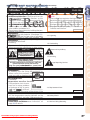
IMPORTANT SAFEGUARDS
Introduction
Before using the projector, please read this operation manual carefully.
instructions
for later use.
the REGISTRATION
CARD packed with the projector.
Info
Introduction
CAUTION
Please read
all offor
these
instructions
you operate
this SHARP
productProjector,
and saveusing
these
There are two :important
reasons
prompt
warranty before
registration
of your new
Introduction
ENGLISH
1. Read Instruc
1. WARRANTY
Electrical
energy can perform many useful functions. This product has been engineered and manufactured to
to assure
that BUT
you IMPROPER
immediatelyUSE
receive
full benefit
of the parts,
service SHOCK
and labor
assureThis
yourispersonal
safety.
CAN the
RESULT
IN POTENTIAL
ELECTRICAL
OR
warranty applicable
purchase.
FIRE HAZARDS.
In order notto
to your
defeat
the safeguards incorporated in this product, observe the following basic
rules
its installation,
use and servicing.
2. for
CONSUMER
PRODUCT
SAFETY ACT
To ensure that you will promptly receive any safety
notification
of inspection, modification, or
13. Power-Cord
Protection
recall
that
may be required
to give
under the 1972
Consumer
Product
SafetysoAct,
All the
safety
andSHARP
operating instructions
should be read
before
Power-supply
cords should
be routed
that PLEASE
they are not
theREAD
product CAREFULLY
is operated.
likely to be walked
on or pinched by itemsU.S.A.
placedONLY
upon or
THE IMPORTANT “LIMITED WARRANTY”
CLAUSE.
against them, paying particular attention to cords at plugs,
2. Retain Instructions
convenience receptacles, and the point where they exit from
The safety and operating instructions should be retained for
WARNING:
theproduct.
beam of light, or view directly. Be especially
future reference. High brightness light source. Do
12not stare intothe
14.the
Lightning
3. Heed Warnings
careful that children do not stare directly into
beam of light.
For added protection for this product during a lightning storm,
or when it is left unattended and unused for long periods of
time, unplug it from the wall outlet and disconnect the cable
This
prevent
damagethis
to theproduct
product due
electric system.
shock,
dowillnot
expose
toto
lightning and power-line surges.
All warnings on the product and in the operating instructions
should be adhered to.
4. Follow Instructions
WARNING:
To reduce the risk of fire or
All operating and use instructions should be followed.
rain or moisture.
5. Cleaning
Unplug this product from the wall outlet before cleaning. Do
not use
liquid cleaners orequipment
aerosol cleaners. Use a damp cloth
Other
connected
See
forbottom
cleaning.of projector.
15. Overloading
Do not overload wall outlets, extension cords, or integral
convenience receptacles as this can result in a risk of fire or
electric shock.
The lightning flash with arrowhead symbol,
6. Attachments
16. Object and
Liquid
Entry triangle, is intended to
within
an equilateral
CAUTION
Do not use attachments not recommended by the product
Never push
objects
of any
kind
into this of
product
through
alert
the
user
to the
presence
uninsulated
manufacturer as
they
cause hazards.
RISK
OFmay
ELECTRIC
SHOCK.
openings“dangerous
as they may voltage”
touch dangerous
points or
within voltage
the product’s
DO NOT REMOVE SCREWS
7. Water and Moisture
short-out enclosure
parts that could
result
fire or electric
shock.
that may
be in
of asufficient
magnitude
SPECIFIED
USER
Do not use this EXCEPT
product near
water–for
example, near a bath
Never spill
of any kind
on the
toliquid
constitute
a risk
orproduct.
electric shock to
tub, wash bowl, kitchen
sink,
or
laundry
tub;
in
a
wet
SERVICE SCREW.
17. Servicing
persons.
basement; or near a swimming pool; and the like.
Do not attempt to service this product yourself as opening or
8. CAUTION:
Accessories
removing
covers
may exposepoint
you towithin
dangerous
voltageisor
TO REDUCE THE RISK OF ELECTRIC SHOCK,
The
exclamation
a triangle
Do not place this product on an unstable cart, stand, tripod,
other hazards.
Refer
all servicing
to the
qualified
service
intended
to
alert
the
user
to
presence
of
DO
NOT
REMOVE
COVER.
bracket, or table. The product may fall, causing serious injury
personnel.
important
operating
and
maintenance
NO
USER-SERVICEABLE
PARTS
EXCEPT
LAMP
UNIT.
to a child or adult, and serious damage to the product. Use
18. Damage(servicing)
Requiring Service
instructions in the literature
REFER
TObracket,
QUALIFIED
SERVICE
only with
a cart,SERVICING
stand, tripod,
or table
recommended
Unplug this
product from the
outlet and refer servicing
accompanying
thewall
product.
PERSONNEL.
by
the
manufacturer,
or
sold
with
the
product.
Any
mounting
to
qualified
service
personnel
under the following conditions:
Using
the
projector
in
other
countries
of the product should follow the manufacturer’s instructions,
a. When the power-supply cord or plug is damaged.
and should use a mounting accessory recommended by the
b. If liquid has been spilled, or objects have fallen into
manufacturer.
the product.
or modifications
to this toequipment
WARNING:
9. TransportationFCC Regulations state that any unauthorized changes
c. If the product
has been exposed
rain or water.not
expressly
approved
by the manufacturer could void
theproduct
user’s does
authority
to operate
this
d. If the
not operate
normally
by equipfollowing
A product and cart
combination
should
the operating instructions. Adjust only those controls
be moved with ment.
care. Quick stops,
U.S.A. ONLY
that are covered by the operating instructions,
as an
excessive force, and uneven surfaces
improper adjustment of other controls may result in
may cause the product and cart
damage and will often require extensive work by a
combination to overturn.
INFORMATION
qualified technician to restore the product to normal
10. Ventilation
This
equipment
andforfound
to comply with operation.
the limits for a Class A digital device,
Slots
and openingshas
in thebeen
cabinettested
are provided
ventilation
e. If the product
has been
dropped or damaged
in any
Temperature
monitor
pursuant
Part
15 of the
FCC
Rules.
are designed
to provide
reasonable
protection
to ensure to
reliable
operation
of function
the
product
and toThese
protect limits
it
way.
from
overheating,
and
these
openings
must
not
be
blocked
against harmful interference when the equipment is operated
in the
a commercial
environment.
Thisin
f. When
product exhibits
a distinct change
or covered. The
openings should
never
becan
blocked
by placing
equipment
generates,
uses,
and
radiate
radio frequency performance,
energy and,
not installed
and
used in
thisifindicates
a need for
service.
the product on a bed, sofa, rug, or other similar surface. This
accordance
the
operation
cause 19.
harmful
interference
Replacement
Parts to radio communications.
product shouldwith
not be
placed
in a built-inmanual,
installationmay
such as
Operation
a residential
area
cause
harmful
interference,
in which
When
replacement
parts
are required, ensure
that thecase
service
a bookcaseoforthis
rackequipment
unless proper in
ventilation
is provided
or is likely to
has used replacement parts specified by the
manufacturer’s
instructionstohave
been adhered
to.
thetheuser
will be required
correct
the interference
at histechnician
own expense.
U.S.A.
ONLY
manufacturer or have the same characteristics as the original
11. Power Sources
part. Unauthorized substitutions may result in fire, electric
This product should be operated only from the type of power
or other
source
indicated
on the marking
If you
are notwith
sure the
of device. shock,
The
enclosed
computer
cablelabel.
must
be used
The cable
is hazards.
provided to ensure that the device
20. Safety Check
the type of
power
supply
to your
home, consult your product
complies
with
FCC
Class
A verification.
Upon completion of any service or repairsU.S.A.
to this ONLY
product,
dealer or local power company. For products intended to
ask the service technician to perform safety checks to
operate from battery power, or other sources, refer to the
determine that the product is in proper operating condition.
operating instructions.
WARNING:
12. Grounding or Polarization
21. Wall or Ceiling Mounting
This
a Class
A product.
Inofathe
domestic
environment
this
maybe
cause
radio
interference
Thisisproduct
is provided
with one
following types
of
Thisproduct
product should
mounted
to a wall
or ceiling onlyinas
59
plugs.case
If the plug
fail to fit
the powerto
outlet,
which
the should
user may
beinto
required
take adequate measures.
recommended by the manufacturer.
please contact your electrician.
Do not defeat the safety purpose of the plug.
a. Two-wire type (mains) plug.
b. Three-wire grounding type (mains) plug with a
grounding terminal.
This plug will only fit into a grounding type power
outlet.
Downloaded From projector-manual.com Sharp Manuals
22. Heat
This product should be situated away from heat sources such
as radiators, heat registers, stoves, or other products
(including amplifiers) that produce heat.
-1
Accesso
Quick
S
When connec
T
e
rm
proj
AUD
How
IMPORTANT
Part
Part
Samples
Connecting
Controlling
Names
Names
toofAccess
the
Cables
to
and
SAFEGUARDS
Video
aProjector
Computer
Functions
and
forEquipment
Connection
the
Functions
by PDF
a Computer
Operation
Manuals
This section shows the basic operation (projector connecting with the computer). For details, see the page
Supplied
PDF operation
Numbers
When
connecting
accessories
in that
manuals
refer
toyou
the
to
the
in
LAN
several
main
terminal
pages
languages
using
in following
thisa operation
are
LANincluded
cablemanual
in the
where
CD-ROM,
the topic
so
that
is explained.
you can
Terminal
on read
Ensure
Remote
Control
the
safeguards
when
described
below
for
each
step.
Equipment
Cable
connectedTo
equipment
work with the projector.
utilize these manuals, you need to install Adobe® Reader ® on your
The projector
employs
DVI
digital®input terminal for direct input
of Digital
Video signals from a
setting
up
your
projector.
STANDBY
button
R/C JACK
® the 30
TX/RXWIRED
LED
(yellow)
computer
(Windows
or Macintosh
). stereo minijack to RCA audio
Setup
and
Projection
Audio-visual
ø3.5 mm
cable
For putting
the projector
into
Illuminates
when transmitting/receiving
data.
For controlling
the projector by
connecting
computer.
Projector
LINK LED
audio output
terminal
equipment
(for
standby
mode.
In
this To
section,
connection
the (commercially
projector
the computer is explained
using
one
example.
the (green)
remote
control
toCOMPUTER/
the projector.
Caution
concerning
theoflamp
unit andavailable)
Audio
Illuminates when linked.
®
®
about
placing
the
projector
in a
COMPONENT
1, 2, DVI-D)
Please
download
Adobe
Reader
(http://www.adobe.com).
■
Potential
hazard
of glass
par- from the InternetWarning
To
input terminal
output
To S-video
output
terminal
ON button
30S-VIDEO
button
32
Top
ViewKEYSTONE
7
STANDBY
high
position
ticles
lamp the
ruptures.
In case
For turning the power on.
Computer
HUB
terminal
For if
entering
Keystone
3 7 STANDBY/ON button
Two R-6 batteries
To AUDIO inputbutton
■ When placing the projector
in terminal
a high posiof orlamp rupture,
your
Accessing
the
PDFcontact
Manuals
Correction
mode.
(“AA”
size,
UM/SUM-3,
RGB
cable
DIN-D-sub
RS-232C
MENU
button
43
nearest
Sharp
Authorized
Protion,
make
certain
it
is
carefully
secured
to
6 INPUT buttons For Macintosh*®:To ensure
safety, do
notbutton
connect
Computer
For
Windows®ENTER
:
For displaying
and the
3adjustment
ON
HP-7
or
similar)
(10'
(3.0
m))
adaptor
button
44
jector
Dealer
or Service
Cen-Connect with the cable adaptor,
Remote
control
Terminal
etc.
avoid
personal
injury
caused
by
the
projecLAN terminal
with
any cables
setting
screens.
57
Insert
theitems
CD-ROM
Insert the CD-ROM
in(5
the
drive.such
setting
selectedin
orthe CD-ROM drive.
/CD-ROM
64" (15 cm))
terFor
for
replacement.
6 ENTER button <QCNWGA045WJPZ>
for using
<RRMCGA623WJSA>
torDouble
falling click
down.
asthe
a telephone
line
that may cause
adjusted
onthe
the“My
menu.
Double
click
Computer”
icon.
“CD-ROM”
icon.
MOUSE/Adjustment
buttons
See “Regarding the Lamp”
<QCNWGA091WJPZ>
Video Equipment
Cable adaptor 39·43
the on
excessive
( view
/ voltage.
/ the
/ ) operation manual
CAUTION
Double
“CD-ROM”
drive.
When you
want to
Power
cord*click the
page
61.
LAN
cable
(Category
5 type,PRECAUCIÓN
commercially available) (commercially
available)
dedicated
moving the computer
cursor
Do
subject theFor
projector
hard
imPRÉCAUTION
(1)When you
(2) operation
(3)Tonot
want button
to view
the
manual
1) Double
“MANUALS”to
folder.
LAN
terminal click the(4)
L-CLICK
39
cable
when with the USB connection
pact
and/or
vibration.
Dedicated
For the
Left click click
when with
2) Double click the
language
of
the
1) Double
the the
“MANUALS”
folder. cable
To(name
DVI-D
input
terminal
(using
a USB cable
or the
optional
To AUDIO input terminal
USB connection
(using a USB
■ Take care with the want
lensto
soview.
as not to hit or
Caution
concerning
setup(name
of theofproreceiver).
(for DVI-D) folder) that you remote
2)Note
Double
click the the
language
the
ø3.5 mm stereo minijack to RCA audio
cable or the optional
jector folder)
To DVI digital
Forofselecting
and adjusting ondamage
theavailable)
surface
the
3) Double
click
the pdf
file lens.
to access the prothat you
want to view.
cable
remote
receiver).
5
Zoom
knob
output
terminal
When
connecting
to
hub,
use
straight-through
Category
5 (commercially
(CAT.5)
type cable
(commercially
available).
■ For For
minimal
servicing
to maintain
high
Foritems.
Australia,
New
For
U.K.,
Hong
Kongscreen
Europe,S-video
except
U.K.
U.S., RCA
Canada,
etc.and For
cable
(commercially
available)
audio cable
jectortype
manuals.
3) Double
click
the
pdf
file touse
access
the proMAGNIFY
(Enlarge/Reduce)
36
When
connecting
to
computer,
cross-over
Category
5
(CAT.5)
cable
(commercially
available).
(commercially
available)
image
quality,
SHARP
recommends
that
this
Zealand
and
Oceania
and
Singapore
(6' (1.8
m))
(6' (1.8 m)) buttons
R-CLICK/RETURN
button
Rest
your
eyes
occasionally.
39·43
RCA
available)
AUDIO
jectorbe
manuals.
you want to
view
the click
setup
manual
projector
installed
in an area
freeaudio
fromcable
hu- 5(commercially
Focus
ringWhen
For (6'
thethe
Rightscreen
whenfor
withlong
the
(1.8
m))
(6'
(1.8 m))
<QACCVA011WJPZ>
<QACCDA007WJPZ>
For enlarging/reducing
part of Audio
the
■
Continuously
watching
(for
VIDEO,
S-VIDEO)
1)
Double
click
the
“SETUP”
folder.
When
you
want
to
view
the
setup
manual
midity, dust and cigarette
smoke. When the
USB connection (using a USB
image.
DVI
Digital cable
6 COMPUTER
1
<QACCLA018WJPZ>
<QACCBA036WJPZ>
hours
will cause
eye
strain.
Take
regular
cable
or
the optional
remote
receiver).
projector
is subjectedoutput
to these environments,
2) Double
click the
language
(name
of the
1)audio
Double
(commercially
available)
To
outputclick the “SETUP” folder.
button
PAGE
Up/Down
buttons
terminal
For
returning
to
the
previous
39
breaks
to
rest
your
eyes.
and
lens
must
be cleaned
more
terminal
*the
Use
the
power
cord
that
corresponds
to the
wall
folder) that you display.
want to view.
2)vents
Double
click
the
language
(name
of
theoutlet in your country.
Same as the [Page Down] and
often.
As
long
as
the
projector
is
regularly
3)
Double
click
the
pdf file to access the setup
folder)
that
you
want
to
view.
[Page Up] keys on a computer
cleaned,
use with
in these
environments
will not
Volumeextremes
buttons
locations
of tem34 with
Terminal
Connect
the cableAvoid
adaptor,manual.
etc.
keyboard,
when
43)Tilt
dial
Double
click the
theUSB
pdf
file to access
thewith
setup
For adjusting the speaker sound
4 unit.
Height Adjustment
buttons
reduce(using
the aoverall
operation
connection
USB cable
or using life of the
for
perature.
manual.
Internal
cleaning
should
be performed
the optional
remote receiver).
* ø3.5 mm stereo
oradaptor
mono audio cable level.
theonly
■Cable
operating
temperature
of ofthe
projector
You can display computer images
on both the projector
and
aThe
separate
monitor
RGB
cables.
(commercially
available
or available
as using two sets
When connec
Connecting to a Monitor with RGB Input Terminal
by a Sharp Authorized
Projector Dealer orSharp service
(commercially
available)
dedicated
part QCNWGA038WJPZ)
is from 41°F to
3495°F (+5°C to +35°C).
35
1.
Place
the projector
facing a screen
Service
Center.
■ The storage temperature of the projector is
BREAK TIMER button
ForTodisplaying
theterminal
break timer.cable
audio output
Front View
AV MUTE button
For temporarily displaying the black
screen and turning off the sound.
Dedicated cable
from –4°F
to 140°F
Storage
case (–20°C to +60°C).
Do
not
set
thebutton
projector
incable,
places
exLensusing
cap up
(attached)
cap
strap
AUTO
SYNC
To
video
terminal
35audioLens
* When
the
ø3.5 output
mm mono
theComputer
volume level willSupplied
be half of when using the ø3.5 mm stereo audio cable.
RGB cable
FREEZE
button
35
posed
sunlight
or <UBNDTA017WJZZ>
bright light.
RCA audio
Tocable
VIDEO
input terminal
For
automatically
adjusting
images
<GCASNA020WJSA>
accessory
Infoto direct
<PCAPHA026WJSA>
For freezing
images.
(commercially
available)
■ when
Position
the toscreen
so that it is not in direct
To AUDIOand
input terminal
connected
a computer.
Do not block
the
intake
exhaust
Monitor
If the desired
pdf light.
file cannot
opened
by double
sunlight
or room
Light be
falling
directly
on clicking the mouse, start Adobe® Reader ® first, then
Operation manual (this manual <TINS-D563WJZZ> vents.
and CD-ROM <UDSKAA102WJZZ>)
37 7 RESIZE button
Monitor
RGB
cable
(supplied
or commercially available)
MONITOR OUTPUT
specify
the desired
fileout
using
“File”,
“Open”
menu.
PICTURE
MODE
button
the
screen
washes
thethecolors,
making
36
■
Allow
at
least
7 /For
8 inches
space
switching(20
the cm)
screenofsize
For
switching
the picture
mode.
RGB
viewing
difficult.
Close
the curtains and dim
Page
18
(NORMAL,
STRETCH,
etc.).
between
the
exhaust
vent
and
the
nearest
inputup the screen in a
the lights when setting
Video Equipment
To COMPUTER/
wall
or
obstruction.
35 ECO+QUIET button
Note
INPUTroom.
buttons
34
terminal
sunny
or bright
COMPONENT 1
2.Codes
Connect the projector to the computer
and
the and
power
■ Ensure that
the plug
intake vent
the exhaust
in “< >” are Replacement parts codes.
For switching to the respective
input terminal
ForTolowering
the
noise
of the cooling
MONITOR
OUT
terminal
fan and extending the lamp life.
input the
modes. AC socket ofTothe
cord into
projector
output
vent are not obstructed. AUDIO
The
projector
may
be safely
tilted
toterminal
aRGB
Amplifier
ø3.5
mm stereo
minijack to RCA audio cable
To RGB input terminal
Optional
accessories
maximum
angle
of
9
degrees.
■
If the
cooling fan
becomes(MONITOR
obstructed,
a pro(commercially available)
OUT)
Using the Remote Control
with a
Signal
Cable
Audio
■ Placement should be
within ±9 degrees of
tection circuit will automatically put the pro■ Lamp unit
AN-C430LP
horizontal.
When the signals
fromcable
theinput
remote control
cannot
reached
dueavailable)
to the
positioning
projector,
use a
RCA audio
Composite
video be
cable
(commercially
jector
into
standby
modeoftothe
prevent
overheat
■ Ceiling-mount adaptor
AN-60KT
■Projector
Ceiling-mount unit
(Rear
view) connecting
When
AN-TK201
<for
AN-60KT>
jector
power
cordcontrol
from the wall outlet and wait
Remote
terminal
(commercially
ø3.5 mm minijack
cable available)
to connect the remote control
to the
projector.
Now
you not
can indicate
control the
projector
damage.
does
a malfuncAN-XGCM55
(forThis
U.S.A.
only)
with
the
remote
control.
■ Universal bracket
AN-JT200
only)
tion (for
(seeU.S.A.
pages
59 and 60). Remove the proTopages
WIRED
WIRED than the computer,
equipmentTo other
seeleast
25,
28 andPlace
29. the projector where
AN-TK202
<for10
AN-60KT>
at
minutes.
REMOTE terminal
R/C JACK
AN-EP101B
<for AN-XGCM55
AN-JT200>
23, 30
Attaching the lens cap
the intake
and exhaust and
vents
are notPages
blocked,
(for
U.S.A.
only)
After putting the lens cap strap on the lens
RGB cable
plug the power cord back in and turn on the
■
Remote
receiver
AN-MR2
Note
cap,
pass
thethe
other
endlens
of the
strap
Remove
the
andcableturn
the
projector
on
When
using
projector
incap
high-altitude
ø3.5
mm minijack
(commercially
available
or
projector.
This will return the projector to the
available
asm))
Sharp
partAN-C3CP2
QCNWGA038WJPZ)
through
the
the
front
side
of
the
RGB
cable
(commercially
available)
■
3 RCA
to hole
15-pin
D-sub
cable
(10'
(3.0with
When
you
connect
video
equipment
a service
21-pin
RGB
output
(Euro-scart)
to the
the remote
projector,
use a comareas
such
as on
mountains
(at
altitudes
ofOn
the projector operatingOn
control
condition.
projector,
to the
lens,meters
as
in
merciallynext
available
cable
thatshown
fits in
the projector
you want to connect.
approximately
1,500
(4,900
feet) terminalnormal
the illustration.
3.
or more)
Note
Note
■ When
you use the projector in high-altitude
The wireless
remote
function
not possible
when the ø3.5 mm minijack cable is connected to the projector.
areas
air, set
“FanisMode”
“High”.
Some with
of thethin
optional
accessories
maytonot
be available depending on the region. Please check with your
Should the wireless
remote
operation
be required,
the ø3.5 mm minijack cable should be disconnected
Neglecting
this
can
affect
the
longevity
of
nearest Sharp Authorized Projector Dealer orthe
Service Center.
from thesystem.
projector.
optical
Page 30
-6 From projector-manual.com Sharp Manuals
Downloaded
Caution rega
IMPORTANT SAFEGUARDS
Introduction
Before using the projector, please read this operation manual carefully.
■
When using
projector,
instructions
forthe
later
use. take care not to subject it to hard impact and/or vibration, as this
1. WARRANTY
can result in damage. Take extra care with the
lens. If you are not to use the projector for a
longCONSUMER
time, make certain
you SAFETY
unplug the
power
2.
PRODUCT
ACT
cord from the wall outlet, and disconnect any
other cables connected to it.
■ Do not carry the projector by holding the lens.
2. Retain Instructions
■ When storing the projector, ensure you attach
WARNING:
the lens cap to the projector. (See page 12.)
Heed
■3.Do
notWarnings
expose the storage case or projector
to direct sunlight or near heat sources. The
4.storage
Follow Instructions
case or projector may change color
WARNING:
or become deformed.
Info
• The cooling fan regulates the internal temperature, and its performance is automatically controlled. The sound of the fan may
change during projector operation due to
changes in
the fan speed. This does not
13. Power-Cord
Protection
indicate malfunction.
Introduction
CAUTION: Please read all of these instructions before you operate this product and save these
Introduction
ENGLISH
1. Read Instruc
5. Cleaning
14. Lightning
15. Overloading
Other connected equipment
■6.When
connecting a computer or other audioAttachments
visual equipmentCAUTION
to the projector, make the
RISK
OF ELECTRIC
SHOCK. the power
connections
AFTER
unplugging
DO NOT REMOVE SCREWS
7. Water and Moisture
cord of the projector
from the
AC outlet and
EXCEPT SPECIFIED
USER
SERVICE SCREW.
turning off the equipment
to be connected.
■8.Please
read the operation manuals of the proAccessories
CAUTION:
TOthe
REDUCE
THE RISKto
OFbe
ELECTRIC
SHOCK,
jector
and
equipment
connected
for
DO NOT REMOVE COVER.
instructions
on how toPARTS
makeEXCEPT
the connections.
NO USER-SERVICEABLE
LAMP UNIT.
Using
REFER SERVICING TO QUALIFIED SERVICE
PERSONNEL.
the projector
in other countries
16. Object and Liquid Entry
17. Servicing
18. Damage Requiring Service
■ The power supply voltage and the shape of
the plug may vary depending on the region
WARNING:
9. Transportation
or country you are using the projector in.
When using the projector overseas, make
sure you use an appropriate power cord for
the country you are in.
INFORMATION
10. Ventilation
Temperature monitor function
■ If the projector starts to overheat due to setup problems
or blockage of the air vents,
“ ” and “
” will illumi11.nate
Power
in the
Sources
lower left corner of the picture. If the
temperature continues to rise, the lamp will turn
off, the temperature warning indicator on the
projector will blink, and after a 90-second cooling-off period the projector will enter the standby
WARNING:
12.mode.
Grounding
or Polarization
Refer
to “Maintenance Indicators” on
page 59 for details.
19. Replacement Parts
20. Safety Check
21. Wall or Ceiling Mounting
22. Heat
Downloaded From projector-manual.com Sharp Manuals
-1
Accesso
Quick
S
When connec
T
e
rm
proj
AUD
How
IMPORTANT
Part
Part
Samples
Connecting
Controlling
Names
Names
toofAccess
the
Cables
to
and
SAFEGUARDS
Video
aProjector
Computer
Functions
and
forEquipment
Connection
the
Functions
by PDF
a Computer
Operation
Manuals
This section shows the basic operation (projector connecting with the computer). For details, see the page
Supplied
PDF operation
Numbers
When
connecting
accessories
in
manuals
refer
to Terminal
the
to
the
in
LAN
main
terminal
pages
languages
using
in thisa operation
are
LANincluded
cablemanual
in the
where
CD-ROM,
the topic
so that
is explained.
you can
on several
described
below
for
each
step.
Equipment
Cable
connectedTo
equipment
work with the projector.
utilize these manuals, you need to install Adobe® Reader ® on your
The projector
employs
the 30
DVI digital®input terminal for direct input
of Digital
Video signals from a
STANDBY
button
R/C JACK
TX/RXWIRED
LED
(yellow)
computer
(Windows® or Macintosh
). stereo minijack to RCA audio
Audio-visual
ø3.5 mm
cable
For putting the projector into
Illuminates
when transmitting/receiving
data.
For controlling
the projector by
connecting
computer.
LINK LED
audio output
terminal
equipment
(for
standby
mode.
In
this To
section,
connection
the (commercially
projector
the computer is explained
using
one
example.
the (green)
remote
control
toCOMPUTER/
the projector.
Caution
concerning
theoflamp
unit andavailable)
Audio
Illuminates when linked.
®
®
about
placing
the
projector
in a
COMPONENT
1, 2, DVI-D)
Please
download
Adobe
Reader
(http://www.adobe.com).
■
Potential
hazard
of glass
par- from the InternetWarning
To
input terminal
output
To S-video
output
terminal
ON button
30S-VIDEO
button
32
Top
ViewKEYSTONE
7
STANDBY
high
position
ticles
lamp the
ruptures.
In case
For turning the power on.
Computer
HUB
terminal
For if
entering
Keystone
3 7 STANDBY/ON button
Two R-6 batteries
To AUDIO inputbutton
■ When placing the projector
in terminal
a high posiof orlamp rupture,
your
Accessing
the
PDFcontact
Manuals
Correction
mode.
(“AA”
size,
UM/SUM-3,
RGB
cable
DIN-D-sub
RS-232C
MENU
button
43
nearest
Sharp
Authorized
Protion,
make
certain
it
is
carefully
secured
to
6 INPUT buttons For Macintosh*®:To ensure
safety, do
notbutton
connect
Computer
For
Windows®ENTER
:
For displaying
and the
3adjustment
ON
HP-7
or
similar)
(10'
(3.0
m))
adaptor
button
44
jector
Dealer
or Service
Cen-Connect with the cable adaptor,
Remote
control
Terminal
etc.
avoid
personal
injury
caused
by
the
projecLAN terminal
with
any cables
setting
screens.
57
Insert
theitems
CD-ROM
Insert the CD-ROM
in(5
the
drive.such
setting
selectedin
orthe CD-ROM drive.
/CD-ROM
64" (15 cm))
terFor
for
replacement.
6 ENTER button <QCNWGA045WJPZ>
for using
<RRMCGA623WJSA>
torDouble
falling click
down.
asthe
a telephone
line
that may cause
adjusted
onthe
the“My
menu.
Double
click
Computer”
icon.
“CD-ROM”
icon.
MOUSE/Adjustment
buttons
See “Regarding the Lamp”
<QCNWGA091WJPZ>
Video Equipment
Cable adaptor 39·43
the on
excessive
( view
/ voltage.
/ the
/ ) operation manual
Double
“CD-ROM”
drive.
When you
want to
Power
cord*click the
page
61.
LAN
cable
(Category
5 type, commercially available) (commercially
available)
dedicated
moving the computer
cursor
Do
subject theFor
projector
hard
im(1)When you
(2) operation manual
(3)Tonot
want button
to view
the
1) Double
“MANUALS”to
folder.
LAN
terminal click the(4)
L-CLICK
39
cable
when with the USB connection
pact
and/or
vibration.
Dedicated
For the
Left click click
when with
2) Double click the
language
of
the
1) Double
the the
“MANUALS”
folder. cable
To(name
DVI-D
input
terminal
(using
a USB cable
or the
optional
To AUDIO input terminal
USB connection
(using a USB
■ Take care with the want
lensto
soview.
as not to hit or
Caution
concerning
setup(name
of theofproreceiver).
(for DVI-D) folder) that you remote
2)Note
Double
click the the
language
the
ø3.5 mm stereo minijack to RCA audio
cable or the optional
jector folder)
To DVI digital
Forofselecting
and adjusting ondamage
theavailable)
surface
the
3) Double
click
the pdf
file lens.
to access the prothat you
want to view.
cable
remote
receiver).
5
Zoom
knob
output
terminal
•
When
connecting
to
hub,
use
straight-through
Category
5 (commercially
(CAT.5)
type cable
(commercially
available).
■ For For
minimal
servicing
to maintain
high
Foritems.
Australia,
New
For
U.K.,
Hong
Kongscreen
Europe,S-video
except
U.K.
U.S., RCA
Canada,
etc.and For
cable
(commercially
available)
audio cable
jectortype
manuals.
3) Double
click
the
pdf
file touse
access
the pro(Enlarge/Reduce)
36
•MAGNIFY
When
connecting
to
computer,
cross-over
Category
5
(CAT.5)
cable
(commercially
available).
(commercially
available)
image
quality,
SHARP
recommends
that
this
Zealand
and
Oceania
and
Singapore
(6' (1.8
m))
(6' (1.8 m)) buttons
R-CLICK/RETURN
button
Rest
your
eyes
occasionally.
39·43
RCA
available)
AUDIO
jectorbe
manuals.
you want to
view
the click
setup
manual
projector
installed
in an area
freeaudio
fromcable
hu- 5(commercially
Focus
ringWhen
For (6'
thethe
Rightscreen
whenfor
withlong
the
(1.8
m))
(6'
(1.8 m))
<QACCVA011WJPZ>
<QACCDA007WJPZ>
For enlarging/reducing
part of Audio
the
■
Continuously
watching
(for
VIDEO,
S-VIDEO)
1)
Double
click
the
“SETUP”
folder.
When
you
want
to
view
the
setup
manual
midity, dust and cigarette
smoke. When the
USB connection (using a USB
image.
DVI
Digital cable
6 COMPUTER
1
<QACCLA018WJPZ>
<QACCBA036WJPZ>
hours
will cause
eye
strain.
Take
regular
cable
or
the optional
remote
receiver).
projector
is subjectedoutput
to these environments,
2) Double
click the
language
(name
of the
1)audio
Double
(commercially
available)
To
outputclick the “SETUP” folder.
button
PAGE
Up/Down
buttons
terminal
For
returning
to
the
previous
39
breaks
to
rest
your
eyes.
and
lens
must
be cleaned
more
terminal
*the
Use
the
power
cord
that
corresponds
to the
wall
folder) that you display.
want to view.
2)vents
Double
click
the
language
(name
of
theoutlet in your country.
Same as the [Page Down] and
often.
As
long
as
the
projector
is
regularly
3)
Double
click
the
pdf file to access the setup
folder)
that
you
want
to
view.
[Page Up] keys on a computer
cleaned,
use with
in these
environments
will not
Volumeextremes
buttons
locations
of tem34 with
Terminal
Connect
the cableAvoid
adaptor,manual.
etc.
keyboard,
when
43)Tilt
dial
Double
click the
theUSB
pdf
file to access
thewith
setup
For adjusting the speaker sound
4 unit.
Height Adjustment
buttons
reduce(using
the aoverall
operation
connection
USB cable
or using life of the
for
perature.
manual.
Internal
cleaning
should
be performed
the optional
remote receiver).
* ø3.5 mm stereo
oradaptor
mono audio cable level.
theonly
■Cable
operating
temperature
of ofthe
projector
You can display computer images
on both the projector
and
aThe
separate
monitor
RGB
cables.
(commercially
available
or available
as using two sets
When connec
Connecting to a Monitor with RGB Input Terminal
by a Sharp Authorized
Projector Dealer orSharp service
(commercially
available)
dedicated
QCNWGA038WJPZ)
AV MUTE
ispart
from
41°F
to
(+5°Cbutton
to +35°C).
3495°F
BREAK
TIMER button 35
Service
Center.
cable
For temporarily
displaying
the black
ForTodisplaying
the
break
timer.
■
The
storage
temperature
of
the
projector
is
output terminal
Dedicated cable
Frontaudio
View
screen and turning off the sound.
from
–4°F
to
140°F
(–20°C
to
+60°C).
Do not
the projector Lens
in places
exStorage case
Lensset
cap up
(attached)
cap strap
AUTO
SYNC
button
To
video
output
terminal
35audio cable, theComputer
* When using
the
ø3.5
mm mono
volume level willSupplied
be half of when using the ø3.5 mm stereo
cable.
Monitor
RGBaudio
cable
FREEZE
button
35
posed
sunlight
or <UBNDTA017WJZZ>
bright light.
RCA audio
Tocable
VIDEO
input terminal
For
automatically
adjusting
images
<GCASNA020WJSA>
accessory
Infoto direct
<PCAPHA026WJSA>
For freezing
images.
(commercially
available)
■ when
Position
the toscreen
so that it is not in direct
To AUDIOand
input terminal
connected
a computer.
Do not block
the
intake
exhaust
•sunlight
If the desired
pdf light.
file cannot
opened
by double
or room
Light be
falling
directly
on clicking the mouse, start Adobe® Reader ® first, then
• Operation manual (this manual <TINS-D563WJZZ> vents.
and CD-ROM <UDSKAA102WJZZ>)
37 7 RESIZE button
Monitor
RGB
cable
(supplied
or commercially available)
MONITOR OUTPUT
specify
the desired
fileout
using
“File”,
“Open”
menu.
PICTURE
MODE
button
the
screen
washes
thethecolors,
making
36
■
Allow
at
least
7 /For
8 inches
space
switching(20
the cm)
screenofsize
For
switching
the picture
mode.
RGB
viewing
difficult.
Close
the curtains and dim
Page
18
(NORMAL,
STRETCH,
etc.).
between
the
exhaust
vent
and
the
nearest
inputup the screen in a
the lights when setting
Video Equipment
To COMPUTER/
wall
or
obstruction.
35 ECO+QUIET button
Note
INPUTroom.
buttons
34
terminal
sunny
or bright
COMPONENT 1
For switching to the respective
• Codes in “< >” are Replacement parts codes.
input
terminal
■ Ensure
ForTolowering
noise
the cooling
MONITOR
OUT
terminal
that the intake
vent the
and
theofexhaust
fan and extending the lamp life.
modes.
output vent are not obstructed.
The
projectorinput
may
be safely
tilted
toTo
aRGB
Amplifier
ø3.5
mm stereo
minijack to RCA audio cable
AUDIO
To RGB input terminal
terminal
Optional
accessories
maximum
angle of 9 degrees.
■ If the cooling fan becomes(MONITOR
obstructed,
a pro(commercially available)
OUT)
Audio
■ Placement should be
within ±9 degrees of
tection circuit will automatically put the pro■ Lamp unit
AN-C430LP
horizontal.
When the signals
fromcable
theinput
remote control
cannot
reached
dueavailable)
to the
positioning
projector,
use a
RCA audio
Composite
video be
cable
(commercially
jector
into
standby
modeoftothe
prevent
overheat
■ Ceiling-mount adaptor
AN-60KT
■Projector
Ceiling-mount unit
(Rear
view) connecting
When
AN-TK201
<for
AN-60KT>
jector
power
cordcontrol
from the wall outlet and wait
Remote
terminal
(commercially
ø3.5 mm minijack
cable available)
to connect the remote control
to the
projector.
Now
you not
can indicate
control the
projector
damage.
does
a malfuncAN-XGCM55
(forThis
U.S.A.
only)
with
the
remote
control.
■ Universal bracket
AN-JT200
only)
tion (for
(seeU.S.A.
pages
59 and 60). Remove the proTopages
WIRED
WIRED than the computer,
equipmentTo other
seeleast
25,
28 andPlace
29. the projector where
AN-TK202
<for10
AN-60KT>
at
minutes.
REMOTE terminal
R/C JACK
AN-EP101B
<for AN-XGCM55
AN-JT200>
23, 30
Attaching the lens cap
the intake
and exhaust and
vents
are notPages
blocked,
(for
U.S.A.
only)
After putting the lens cap strap on the lens
RGB cable
plug the power cord back in and turn on the
■
Remote
receiver
AN-MR2
Note
cap,
pass
thethe
other
end of the
strap
When
using
projector
inø3.5
high-altitude
mm minijack cable (commercially available or
projector. This will return the projector to the
available
asm))
Sharp
partAN-C3CP2
QCNWGA038WJPZ)
through
the
the
front
side
of
the
RGB
cable
(commercially
available)
■
3 RCA
to hole
15-pin
D-sub
cable
(10'
(3.0with
• When
you
connect
video
equipment
a service
21-pin
RGB
output (Euro-scart)On
to the
the remote
projector,
use a comareas
such
as on
mountains
(at
altitudes
ofOn
the
projector
control
operating
condition.
projector,
to the
lens,meters
as
in
merciallynext
available
cable
thatshown
fits in
the projector
you want
to connect.
approximately
1,500
(4,900
feet) terminalnormal
the illustration.
or more)
Note
Note
■ When
you use the projector in high-altitude
•areas
The wireless
remote
function
not possible
when the ø3.5 mm minijack cable is connected to the projector.
air, set
“FanisMode”
“High”.
• Some with
of thethin
optional
accessories
maytonot
be available depending on the region. Please check with your
Should the wireless
remote
operation
be required,
the ø3.5 mm minijack cable should be disconnected
Neglecting
this
can
affect
the
longevity
of
nearest Sharp Authorized Projector Dealer orthe
Service Center.
from thesystem.
projector.
optical
Page 30
-6 From projector-manual.com Sharp Manuals
Downloaded
Introduction
Connecting
Signal
Screen
Computer
Specifications
Adjustment
Adjustment
Compatibility
to Video
aSet
Computer
(Òduring
S
(ÒS
Equipment
IG-ADJÓ
CR-ADJÓ
Chart
Menu)
Menu)(ÒPRJ-ADJ Ó menu)
Helpful
Functions
Installation
.4 a■gle▼hAdjus
• This projector is equipped with an A
Ò uto V-Keystone
Adjust the projector angle
CorrectionÓ
function that automatically correctsP any
• Adjust melborP the projector angle using the Height
k Chec
ega
trapezoidal
distortion
within
the
projected
image.
Menu
operation
Page 43
buttons. ensure
Optional
TBefore
he image quali▼y Computer
s higes▼ i■ ordÒS
e ofModel
▼he Comp■e▼ sig■al, ▼he Adjustment
RGB sigignal
■al, ▼he usalo■diAS-video sig■al ■d ▼he
connecting,
lenses
the
power
cord
of
the
projector
from
the
AC
outlet
is
unplugged,
XG-C455W/PG-C355W
•
I
▼
f
h
p
e
i
c
u
r
■
s
o
m
a
l
,
d
b
k
g
adjustment (SIG-ADJ)Ó menu
the
Tilt
dial
to adjust
horizontalare
tilt of
audociyrm-p▼veqI■RsfGhBla•Vand
ig,do. •Mul▼ipesg■aDisplay
the
devices
to
be the
connected
turned0.74"
off.
After
making
turn on the
Insert
the
new
lamp
unit.
heardocsi■ly that
upor ▼ ■Rotate
eP1li2x—Ck:7o0cMHz Projection
devices
LCD panel
× 3 all connections,
Pic▼. Pic▼. Pic▼.
SIG SCR — ADJ
SCR
Ne▼.PRJ
SCR-ADJ
Ne▼.
SIG SIG
-ADPRJ This wlec▼■o afyudrmb.phgs
Ne▼.
Lens
distance
for 100" screen size
the
projector.
•Enter
Press
the
lamp
unit
firmly
into
the
lamp
Cprojector
OMPUTER/ N ▼ermi■al1o2 ▼heprojc vfide o■c▼ . Horiz■▼eaql1u5F—cy0:Main
then
the
other
devices.
When
connecting
a
computer,
ensure
that
it
is the last
from▼hecabi■. 1Menu
.
c
■
a
m
o
f
r
e
p
i
▼
kHz
S
y
■
c
s
i
C
g
o
m
a
p
l
:
▼
T
b
e
L
w
v
h
l
a
m
r
o
N
0
Clock Resiz Au▼oPwerOf and
■
O
Wide-zoom
lens
(×
1.5
–
1.9)
AN-C12MZ
10'
5"
–
13'
1"
(3.2
m
–
4.0
m)
Resolution
WXGA
(1280
×
800)
the same keycode
in ÒRe-con0 *4 0
Phase ImageShif▼ Au▼oResar
-150
+150 Fasten
Clock turned
SIG-ADJ e V
O■ all
r 1▼riecqaul43■F—8y5:Hz 2Tele-zoom
unit
compartment.
thethe
securing
•
C
o
m
p
a
▼
i
l
b
e
w
h
s
y
■
c
o
r
e
g
i
■
a
l
device
to
be
on
after
connections
are
made.
lens
(×
2.2
–
2.8)
AN-C18MZ
15'
7"
–
19'
10"
(4.8
m
–
6.0
m)
M
a
i
■
▼
e
c
•
e
S
c
▼
■
i
a
M
.
s
r
o
d
I
95 from
F
number
Lens
FUsed
1.7 –function
1.9
When
the
imageallows
is projected
either
top image.
or
to
automatically
adjust
afrom
computer
This
you
to set
the the
audio
output
0 *4 equipment
0
H-Pos H-Keys▼o■ Sys▼emou■d .
O■
3firmÓ
When
connecting
video
with atoDVI
output
terminal
Page following
47
Phase is a list
The
VESA.
However,
this
projector
supports
other signals
screws.
lens (×-30 of
3.3+30 modes
–0 *5 0 5.1)O■ that conform
AN-C27MZ
23'
2" –speaker
35'
8"
(7.1
m
–
10.9
m)
orilum■a▼esdc 34Tele-zoom
V-Pos V-Keys▼o■ Speakr
.s■oi▼cegkamr fdbe■ vah▼coebsi dhf▼lau■moireph▼sEthat
the
bottom
towards
the
screen
at
an
angle,
the
image
beof
the
internal
to
O
Ò
nÓ
or
O
Ò
ffÓ
such
as
Zoom
Manual,
× 1.2items
(f = 28.0 – you
33.6 to
mm)
H-Pos
-150
+150
are
Selectable
Description
function
initialize
Au▼oV-Keys■ AudioO▼ Res▼ VESA
Tele-zoom
lensstandards.
(×
5.1
–*5 7.2)O■ FAO
AN-C41MZ This
36' 2"allows
– 50' 10" (11.0
m – 15.5the
m) settings
5
b red.i■lks not
comes
distorted
trapezoidally.
The
function
for
correctwhen
the
projector
is
connected
to
an
external
640x8 O■ E■able
-60
+60
Focus
V-Pos
Manual
246 Resolu▼i■ OSDisplay Mo■i▼rOu
On
Auto
Sync
adjustment will occur
you
have made
inRGB
the
projector.
Horizontal Frequency
Vertical
Frequency
Analog
Digitalwhen
Video
Equipment
*5 •
Resolution
VESA
Au▼oSy■c Backgrou■d LAN/RS23C
Log E■able
When
with(Compatible
the
cable
beca■o▼prjTh Mode
se▼.ikyloc Th O■ RGB
35 RGB
357N o ▼ e connecting
ing
distortion
is called
Keystone
amplifier.
Res▼
(Hz
) trapezoidalSupport
Support
the projector
is
turned
on orCorrection.
when
the
(kHz
) HDCP)
DVI-D
with
Input
terminals
×
1
Ce■▼r 960bps
Au▼o attached
68 Sig■alType Me■uPosi▼ RS-23C
4standard
The
zoom
lens
is
to
the
projector.
d
e
■
r
u
▼
o
p
i
h
.
d
e
k
c
o
l
r
a
s
■
▼
u
b
h
,
N
O
e
i
y
k
h
▼
f
I
e
g
a
P
47
60
27.0
input
signals
are
switched,
when
the
keycode
that
you
have
al(Co■ec▼ig OMPUTER/CheNilusa1▼ro■w2:b .fh)emr To 5cancel
e
d
o
M
J
R
P
e
g
R
c
i
m
a
■
y
D
▼
■
o
r
F
r
d
■
a
▼
S
Fa■Mode
79
Normal
Selectable items
Description
Computer/Component
× 2
70
31.5
640
◊ 350
s▼a■dbymoeuigh 6optional
The
are also available
application.
Please see
VideoSys▼m La■gue Sys▼emLock
to a computer.
Resolu▼i■ lenses from Sharp
Au▼o E■glish Disable
80 set
85
Autofor
V-Keystone
Correction
ready
On
The connected
audio
signal
is output from the internal
N o ▼ e specialized
(mini D-sub 15
pin) 37.9
60
27.0
Alres▼
Ayour
NDBY/Ou▼o■b ST • Pres qnearest
audio output terminals
Page
47 To
Off
Auto
Sync
adjustment
is
not automatiSharp
Authorized
Projector
Dealer
for
details
on
all
the
lenses.
(Refer
to the
70
" s ▼ e p i ■ mf o r u j h c
640◊ 400
speaker.
S-Video (miniO■ DIN 431.5
pin)
× 1
Set
on the ÒSCR-ADJÓ screen
i■▼alzed. b ca■o▼ meu or i▼ems folw■g The ÒAuto V-KeystoneÓ
85
Height
. projec▼h Adjustment
37.9
Sig■alIfo:80x6 Au▼oSy■c
cally
performed.
4
a
■
d
5
b
o
v
e
.
SETUP
MANUAL
on
the
supplied
CD-ROM
for
details.)
Also,
be
sure
to
have
service
person7
Off
The
audio
signal
is
not
output
from the
Of
60 Suplied
27.0
H
60.3 kHz ◊ 47
/V 350 37.8Hz
buttons
Page 720
Video
(RCA)
menu
.
× 1
• SIG-ADJme■u to ÒOnÓinternal
w LampTier(f)[0]h■1%
70
31.5
RGBcable
dial
wi▼hgre■sPcu install
•*6 unit
Cha■ge▼ipusly. Tilt
7
4
speaker.
When
the
System
Lock
is
set
nel
the
optional
lenses.
Replace
the
lamp
cover.
y
r
o
s
e
c
a
To
AUDIO
input
terminal
60
27.0
VGA
Sig■alType
Au▼o
Pages 31, 32
To DVI-D
Audio
minijack)
× 2
70 Resolu▼i■
31.5
720
◊ 400 (ø3.5 mm stereo
(for COMPUTER/COMPONENT
2, DVI-D)
■ e r c s ▼ u p ■ i e d o c y e k e h ▼ , ▼sig■alpucome s i •k c o L m e ▼ s y S ■ e h W • Align
RGB ENTR and
slide
ENTR ENTR
SEL./ADJ SEL./ADJ SEL./ADJ thePage lamp
input terminal
85
37.9 it to
47 unit cover
Manual
Keystone
Correction
•
S
C
R
A
D
J
m
e
■
u
▼
e
■
p
m
o
C
Note
(RCA)
-pa ▼i ■ehW .■o de ru▼ si rewop h▼ re fa sr ep a (COMPUTER/ close.
× 2
50(L/R)
RETUN RETUN RETUN
26.2
END
ThenAudio
tighten
the END ENDuser
service
60 La■gu e
31.5
. *7
.DVI-)2,■1COMPNEToi▼cejorp ▼Output
a s o▼ edocyek ▼hgir eh▼ re ■ ,sraep zom▼hea■dfcusAj terminals Computer/Component
ø3.5 mm stereo minijack
touto
RCASync
audio cable
×
1
70
34.7
• Auto
adjustment
also performed
Set
ÒA
V-KeystoneÓ
on theisÒSCR-ADJÓ
screen by
e
g
R
c
i
m
a
■
y
D
o
▼
u
A
640◊ 480
screw to secure
the lamp
unit cover.
Computer
72• PRJ-AD me■u
37.9 (commercially available)
S▼a■dr
(mini
D-sub
15
pin)
gThe
re■)(opiksPc▼u Input
e
g
a
P
48
pressing
AUTO
SYNC
on
the
projector
orlevel
on
75
37.5
menu
to
Ò
O
ffÓ
.
Select
Ò
V
-KeystoneÓ
,
and
then
d
e
c
a
h
■
E
screen
for keycode
graph
below
isimage
for 100
(254 cm) screen
Signal
Input
Mode).
Bring
the
projected
intoinches
focus43.3
Adjust
the16:10
projected
image
size (Normal
ThisLTaimperwith
determines
whether
the audio
()f function
85
wi▼hRGB■pusgal
Audio (ø3.5*8 mm stereo
minijack)
× 1
(variable
audio
output)
the
remote
control.
DVI Digital cable
(commercially
available)
press
or
to
parallelize
the
left
and
right
sides
50
31.3
Uservicw Adjust
VideoSys▼m
output
from
the AUDIO
output
• Bring
• 56
projected
image into
by
the projected
image
size(MONITOR
by moving output)
the
— — Au▼o — — focus
Sys▼emLock (COMPUTER/ the
Sys▼em Lock
Info
35.2
To DVIimage
outputLAN
terminal
• the
The projected
Auto
Syncor
adjustment
may
take
some
time
IfScreen
the
optimum
bePAL obtained
of
image
with
the
slide
bar.
To
(RJ-45)
Control
and
× 1
Page
48cannot
60
(forlampu■i▼cve) zoom
37.9with Auto
terminal
is
fixed
variable
by
linking
with
VOLrotating
the
focus
ring.
knob.
SECAM
Description
Selectable
items
DVI-)2,1COMPNET • IfSVGA
. SIG-ADJ
70 to complete, depending on the image of the
46.6
800
◊ 600
the
lamp
unit
and
lamp
unit
cover
are
not
3
.
4
C
S
T
N
Focus
ring
Zoom
knob
Sync
adjustment,
use
the
function.
parallelize
the
upper
and
lower
sides,
select
ÒHTo
audio
output
terminal
USB
(Type
B)
communication
×
1
72
To
COMPUTER/
48.1
UME.
The projector
automatically
enters the 75
On Note
Wide-zoom
(AN-C12MZ)
To
AUDIO
input terminal
46.9
br▼oisPcueterminals
a■dgh correctly
• se▼.i■corlyadjumIg NTSC3.58PAL-Mlens
54
computer
connected
to
installed,
the
power
will
not
turn
COMPONENT ×1 1
KeystoneÓ
and
press
or the. projector.
RGB
outputRS-232C
terminal
(mini
DIN
9input
pin)
N o ▼ e Toitems
standby
modeDescription
when
no53.7
signal
is 85
Selectable
10'5"–13'1"
(3.2
m–4.0
m) input
Selectable items
Description
PAL-N
terminal 50
.
h
s
i
▼
w
40.3
•
For
details
of
the
Resize
mode,
see
pages
37
on,
even
if
the
power
cord
is
connected
to
0
6
L
A
P
detected
for
15noise.
minutes
or longer.
Throw
distance
ratio
1:1.5–1.9
Clock
Adjusts
vertical
Wired
Remote
× 1
60
48.4
FAO
Audio toutput
that does not vary in
• Sel c▼ h i■pu s g al▼y eof h vid qu pme■▼.S ag
47.
Vertical
Keystone
Correction
38. the
Locking
Operation
the
70
56.5
1024
XGAprojector.
ou
elsof▼hvkacTb and
• E■haced) or Sl▼DymiRgs( Buttons
84
Auto
Power
Off
function
Off
Phase
Adjusts
horizontal
noise
(similaron
towill be
Sig■alIfo The
(ø3◊ .5768
mm
stereo
minijack)
(Fixed Audio Zstrength
with the
volume level
of the
• While ▼ proj c is ■ ec▼ d o vi equ pm ■▼ ha s ■ HDMI ou▼p er mi■al, o y ▼he vid o
75
60.0
oom
m in
can also
on the remote
conwba■digormesh • You
. ▼haresuli■bpcqy VCR).
You
can
confirm
the
cumulative
85
68.7
Page press
48 RESIZE
Zoo lamp usage time
disabled.
tracking
on
your
the
Projector
Output)
source
projector.
Speakers
260
W (Mono)
s i g ■ a l c b e i p u ▼ o ( h C e ■ r . cj ▼ U D I o O i A p u e r m i ■ o a l f u d p ▼ . )
45.0
1280◊ 720
Standard
zoom
lens37.)
trol when
to setinputting
theCenters
resize
mode.
(See
page
VI- adewh■D prf Item
H-Pos
the
on-screen
image
by butand
life that
(percentage).
*4
RGB
signal
through
COMPUTER/COMPONENT
or 2 Audiolamp
60
47.8
1280
◊ to
768
VAOthe1remaining
output
varies in strength with
Use
lock
the
operation
• Dep■digosecfia▼o■sWXGA
vide qupm■▼orVHIDMdigalc,eb▼hsig■alrmsio■ this function
275
60 W
m–4.5 m)
49.7
1280COMPUTER/COMPONENT
◊ 800
*5Projection
Item selc▼d.iDwhen lamp
inputting
1
or
2
moving
it12'4"–14'9"
to the left or(3.8
right.
(Variable
the
volume
level
of the
projector.
This
function
allows
you
to
select
the source
input sig75
62.8
tons
on
the
projector.
y
■
m
o
a
▼
w
(
r
T
h
k
e
p
H
.
D
M
I
s
c
i
f
▼
y
a
o
■
d
e
s
▼
u
p
o
r
▼
a
l
c
o
■
e
i
s
▼
v
d
e
o
q
u
i
p
m
■
▼
Throw
distance
ratio
1:1.8–2.1
L 100
ampusgeco■di▼ – 240 V
Remai■ g l mpe if
*6
ItemNote
when
selecting
Rated
voltage
AC
60
47.7 by 1, 2 or DVI-D
1360COMPUTER/COMPONENT
◊ 768
V-Pos
Centers
the on-screen
image
Audio
Output)
■
a
f
g
i
l
o
c
e
h
T
•
,
e
h
▼
g
■
i
l
o
c
r
u
a
d
s
j
p
W
m
nal
type
RGB
or
Component
for
COMPUTER/
60
47.8
1366DVI-D
◊ 768
*7 Item
selecting
▼ha sHDMIdig▼aloup er mi■alusgVHIDMdi▼oalce.b) when
Life
10 %
5%
moving
it up or Buttons
down.
Rated
frequency
50/60
Hz
60
55.0
Locking
theAuto
Operation
f . a■s▼eruf function
COMPONENT
1, 2 or DVI-D.
Page 33
*8 • Item
selecting
S-VIDEO
When
is set to ÒOnÓ
,
70
66.2
1152VIDEO
◊ Power
864 or Off
F orde▼ails■comp▼iblrycfo■e▼i,s upor.▼i■fmaVIocbecoms■iyeD▼i■pvrodybhe whenthe
O p e ar ▼ dx c l u s i v y A
Input
current
75
3.6
67.5
SXGA
Hold
down
ENTER
on
the
projector
for
about
5
secTele-zoom
lens
(AN-C18MZ)
Reset
the
lamp
timer
after
replacing
the
lamp.
Info
Horizontal
Keystone
Correction
A
p
r
o
x
.
A
p
r
o
x
.
ligh▼■odesampT 5
•
e
h
T
p
m
a
l
r
o
▼
c
d
■
i
s
g
u
.
95
minutes1280
before
the
projector
enters
the
v
i
d
e
o
q
u
p
m
■
▼
a
.
c
f
r
e
60
64.0
◊ 1024
ModeEc+Qui▼ whl
Selectable
items
Description
You
can
move
the projected
image
vertically.
15'7"–19'10"
(4.8
m–6.0 m) 360
onds
the
projector
is
being
on. STANDBY
75 W (3.4 W) with AC 1003,0 hours V 150hours
80.0
consumption
(Standby)
ÒSPower
creen
adjustment
(SCR-ADJ)Ó
menu
upev■af▼rh while
Replac▼hm. turned
Note
standby
mode,
the
message
Ò
E
nter
d
o
m
T
U
P
N
I
h
▼
c
l
e
S
•
When
A
Ò
udio
OutÓ
has
been
set
to
V
Ò
AOÓ
,
first make
64.0 ratio 1:2.2–2.860
Auto
Input signals are automatically recogO■.is
Throw
distance
1400◊ 1050
SXGA+
RGB
cable
345
W
(4.4 to
W) lower
with ACthe
240 volume
V
60
65.3
projec▼u■s. Info
mode
in
X
min.Ó
will
appear
on
the
screen
to
sure
of
the
projector
before
On-screen
Display
nized
as
RGB
or
component.
When
connecting
video
equipment
with
component
video
output
terminal
•Main
To
reset
all
adjustment
items,
select
“
R
eset”
and
60
75.0
1600◊ 1200
UXGA
Opera▼ d xclusive y
Menu
Sub Menu
the C
Ò temperature
OMPUTER
using the minutes.
INPUT
buttons on the projector
or
1 button
on
the
control.
Ap rox.
Aprox. remote
Operation
67
41°
F turning
to the
95° COMPUTER
F (+5°
Cpower
to
+35°
C)
34.9
640
◊ 1Ó
480
13"
indicate
the
remaining
TSCR-ADJ helampsud■y▼r Select
the
on
or
off
and
when
switching
the
RGB
Set
when
RGB
signals
are
received.
• MAC
Make
sure
to
reset
the
lamp
timer
only
w
h
E
i
c
l
o
e
+
Q
u
▼
M
d
press
75
832◊ 624
MAC
16"ENTER.
Resiz Keylock
functionNormal ON 49.7
(Co■ec▼ig OMPUTER/CheNilusa1▼ro■w2:b .fh)emr Cabinet
2,0 hours 10 hours Display
Tele-zoom
(AN-C27MZ)
75
60.2the
◊ On
768
19"On
Component
Plastic
projec▼i■.duMAC
gf when
Set
when Component
signals
are
input.
Ful you reset
replacing
the
lamp.
If-Pos”
" INPUTlens
"
list
On-screen
(RGB)
thePage 1024
the
remote
49
O
f
i
s
.
• Page MAC
The49
adjustable
range
of
“
H
(H-Position)
75m–10.9
68.7 23'2"–35'8" (7.1
1152◊ 870
21"
Do▼By * ø3.5 mm
AC m)
socket
stereo
or mono audio cable
1/64"
control
lampprojector
timer and body
continue
to
same
only)
× Hthe
× depending
D]
32" × 4"service
× 11received.
12 27/as
AreaZom (commercially
• [W
co■e▼dhrpjilyCabs use
23- 9
• Thyelkocfu■▼i desDimensions
oacf▼h perio■ some▼iagTh and
INPUT
available
or available
“V-Pos”(main
(V-Position)
may
vary
COMPUTER1
Throw
distance
ratioSharp
1:3.3–5.1 part QCNWGA038WJPZ)
V-S▼rech
ImageShif▼
-40
+40
lamp, this
may cause the
lamp
to
become
Video
Equipment
button
button
(326
×
101.5
×
279.5
mm)
f
l
i
c
k
e
r
s
.
.
r
o
▼
■
m
p
i
u
q
e
w
s
k
y
l
S▼rech
wi▼h ermo c■▼lbuos. on
RGB
the screen
of the computer.
Page resolution
49
COMPUTER1
1024◊ 768
N o ▼ e (approx.)
orH-Keys▼o■ explode.
• .,replac▼hm Ifis■quy
26
10.8 lbs. (4.9 kg)
• Selectable
Y Weight
ouca■▼syelhkf io■w e▼hpr- damaged
-60
+60 Description
items
* w•huoabiesfl¿▼W■m3v.gr5cd, • ThisYou
N
o
▼
e
COMPUTER2 Note
Tele-zoom
lens
(AN-C41MZ)
can
also
reset
the
lamp
timer
via
the
e
g
a
P
49
jec▼oriswam■gup. esalo■gThmp▼k projec▼ym■a bel ▼odisypamge fro ■▼ebkcompu▼ersi■ lmaeousT(/CLRD)
• e■▼ualydobchg.v Tmpwi is unplugged from the
26
If the power cord
On
36'2"–50'10" (11.0 m–15.5 m)
V-Keys▼o■
-10
+10
D DVI-D Computer
Shoulmd▼,i.esrLAN.
c■fhLCDdisyop▼lae bkcmpu▼era■do hiysp▼la o■.▼ur ime
. Replac▼hm . Thelampsrcd▼■ofi
outlet
or the
breaker
switch is turned
off • The
I
▼
i
s
r
e
c
o
m
■
d
▼
h
a
▼
h
e
l
a
m
p
b
e
c
h
a
■
g
e
d
To audio output
terminal
Keystone
Correction
can
be
adjusted
up to
Throw distance ratio 1:5.1–7.2
ageippmloadrsc■buf▼yro▼oefkcpmspulircyof ■▼iuos mprevo ■▼,SHARPres v ▼herigh▼ omaekdsig■ tothe
Page SETUP
49 MANUAL
Taking
Keylock
off
the
onisthe
supDe▼aiTmloCs■d.RAwyhsc(Refer
when
the projector
on, then the
w
h
e
■
▼
r
m
a
i
■
g
l
p
f
e
b
c
o
m
s
5
%
.
No▼e
When
set
to
E
Ò
nableÓ
,
the
function
is
activated
To component
video
output
terminal
an
angle
of
approximately
±12
degrees
with
A
“ uto
e
r
u
▼
c
i
P
s
a
d
.
k
■
O
Au▼oV-Keys■
• input
When
you press
the 5INPUT
buttons on the projector, the INPUT list appears.
oape■rplied
d▼ismul.cfia▼o■chagesofrp ddown
uc▼impervo■▼wihou▼pr io T■he▼ipc.orf ma■ce CD-ROM
Hold
ENTER
on
projector
for about
seconds.
forthe
details.)
Ordinarily,
the type
of
signal
and
Of is detected
projector
automatically
turns
onthe
when and
• press
Remai■g lamp eif cha■gespower
w i ▼ h ■ e a r■ g
Page Compu▼er aibl▼yChorafis cmpu▼erig■alscomp▼ewbih roj.c▼ 49 Press
is consumed
even
in
the
standby
mode.
• WShep■ag▼isrojec siv640 co■▼rlemTh
65
V-Keystone”
and
up
toLamp
an
angle
of approximately
To list,
COMPUTER/COMPONENT
1 ×
'
"
/"
to
select
an
item
on
the
and
R
E
T
N
to
switch
to
the
selected
INPUT
mode.
indicator
•
×
V
G
E
3
A
o
S
5
r
0
s
i
f
g
■
m
6
a
4
l
,
▼
4
a
0
p
e
r
s
o
■
▼
h
c
e
.
To
AUDIO
•
s
e
▼
a
h
o
m
r
l
■
c
i
w
g
p
j
O
5
1
specif a▼o■figuresi■dca▼e r ■omialvuesofprduc▼io■Thuer▼s.ymabe om resolution
correct
mode
is automatically
selected.
Howyc■euqrf h▼ ■o gidep ■wohs eula v eh▼ fo recommended
the
power
cord O■is plugged
into
theinput
ACterminal
OSDisplay
Display
terminal
It is
be
totoD
Ò is• When using
the remote control,
press
1RETUPMOC ±50
, IVthat
D
O-Keystone”
EDIV-S function
or
OEDinput
IV set
degrees/2 with
“V,the
and
approxiep Ty la■giS h▼iw D-IV D ro 2 ,1 TN•EOPMC/RETUPOn-screen
MOC g■isu la■gis ecarl▼■i BGR eh▼ g■icejorp ■ WUsewi▼hcompuersig■alo▼her ■ osli▼eydcmau so f▼heu■cios▼ wr k. ca■o▼beusd.
. se■orc▼lm Of resolution
ever,
for
some
signals,
the
optimal
mode
in
Page
50or
Note
outlet
the
breaker
switch
is
turned
on.
v
d
i
e
a
▼
o
■
s
f
r
m
▼
h
e
s
a
v
l
u
i
■
d
v
i
u
a
l
■
i
▼
.
s
a▼whiEco+QueMsdO■▼o when it is not connected.
STANDBY/ON
button
s o m e M a c i ■ ▼ o s h c o m p u ▼ . e r s C o ■ a c ▼ o u yr ■ e a r s ▼
. oediV-Sro ediV reh▼isu,eacsih▼■I .deris ade▼cjorpeb▼•■y ameg i h▼,BGR ro ▼u A o▼ esA Maci■▼osh adp▼or yma be requid orf use wi▼h Connect
ableÓ
This
reduces
power
switch
the
INPUT
mode.
mately
±30
degrees
with
“
H
-Keystone”
.
the power
• . yfrom▼hepjcaw b Thermo▼c■la cord.
Backgrou■d
Keylock
function
Log OFF
5
5
3
4 Auto
Keystone
Correction
Sync
Adjustment
Returning
to
the Default
Speaker
Setting
Settings
Quick Start
6
Throw
Distance
.5
1 Auto
Adjusting
theResize
Computer
Image
Setting
the
Mode
1
Power
Off Function
Keylock Function
5
Audio Output Type Setting
Connections
Checking the Lamp Life
Status
4 Signal Type Setting
Resetting the Lamp Timer
2 Adjusting the Image Position
.6
2 Auto Restart Function
Useful Features
2 Resolution Setting
6 Monitor Output
7 LAN/RS232C
1
projector
does
not
auto- 30 a■dOf(Se. pag
Ò Off
ResolutionÓ
onThe
the10
Ò SIG-ADJÓ
menu
may
needon
to be
20 turn
40 the projector
50in the
55(ft)
46.)
Page
34
• • ■oi▼ulgeyrsf,hda■cSpim▼bouDM sh.ealr This
Blue in some RESIZE
function
only
works
consumption
when
is
standby
• When the screen
is slanting
orbutton
the
image
is dePage power
50 cord
• display
▼heo■siglfurcadI the
• Plug
the
into
thepower
AC
socket
matically
when
cord
is
ENTER
No■e
selected
to
match
the
computer
mode.
•
T
h
e
l
a
m
p
e
l
i
f
y
m
a
r
v
y
d
e
p
■
i
g
o
■
▼
h
e
u
s
-mocer si ▼ ,deg■ahc eb •▼o■ac sg■i▼e h▼ fI .▼up o la■Whgei■s ▼rhee▼upmoc eprho▼j•ec▼fo sg■i▼ise h▼i■k cehC s▼a■dby.▼■emsujmdodaDepending
on
the
computer
you
are
using,
an
image
may
not
be
projected
unless
the
computerÕ
s
modes.
(See
pages
37
and
38.)
mode.
e, you ca■
teriorated,
set “Auto V-Keystone” to “Off”.
RCA
(Component)
to 15-pin
cable
,place▼hrojwi sm■ projec▼ AC outlet3or
of theoutput
projector.
plugged
the
the
ageco■di▼ . ÒF5Ó D-sub
o▼sd■peroc▼ah e■o•▼ es b■oi▼ulser h▼ a de■mexternal
1280
× 8 0.
Me■uPosi▼
" button
Ce■▼r
portinto
is
switched
on. (e.g.
Press
ÒFnÓ and
keys
simultaneously
when using a
(optional:
AN-C3CP2)
To
reset
this
function,
select
“
0
”
.
u T r■ foPwer▼h breaker
rel as ▼h k y oc b ldi■g ow
ENTER
Selectable items
Description
switchys▼ro■glih.ecdb waf UperRigh▼ is turned
on. a■d
Page
50 computer).
SHARP notebook
e rR ▼ fo h s p c i ■ ▼ r u c i o s ■ y r m p u ▼ e a i o ■ l ▼
LowerRigh▼
Enable
The function
is button
activated even
if the
Note
STANDBY/ON
ro f ylsuoe■a▼ mi r c jo p eh▼ ■o
MENU
UperLf▼
•
e
k
a
M
.
y
e
b
▼
l
p
d
r
o
s
■
i
h
T
a
m
c
51 mode.
e
■
l
a
b
o
y
u
r
c
x
m
s
▼
p
e
■
a
l
o
u
▼
p
r
▼
.
DTV
the STANDBY
button,
then timer.
press that
button again while the confirmation message is displayed,
to put the
projector
into standby
Lowerf▼
Reset
the
lamp
projector
is
in
standby
mode.
abou▼5sec■Press
d. • See
sure▼hbai■ dcoly.w ø3.5on
“Checking othe
Input
Signal”
48
for audio cable(Hz
mmpage
minijack
to RCA
(commercially
available)
3 Signal
" ) On-screen
Setting
the
Confirmation
ntal
Frequency
Vertical
DVI
Support
Display
The
function is switched off when the
Fro■▼ (kHz) down
PRJMode
• While Horiz
simultaneously
holding
" , FrequencyDisable
Ceil■g+Fro▼
information
on
the
currently
selected
input
sig480
60
15.7
On
the
projector
On
the
remote
control
Page and 50
projector
is in standby mode.
This projec▼ is equpd wi▼h a miI.c▼rsope fma■c ould be rsaldyv ec▼f yb 480P
ENTER
MENU
on
the
projector,
r
a
e
R
Info
Sound) 60
31.5
nal.Sound (System
Ceil■g+Rar
33.8 on the projector and 60
press STANDBY/ON
i■core▼ pa orIfei■▼.chs ould hape■, ulg ▼he projc a■d plug i▼ ■ agi • -sid : ro▼cejp h eliw ▼s eb ▼o■ac klyeK 540P
15.6
576
E■glish
polski
No▼e
allLa■gue four buttons
pressed
down
until 50
af▼ermoh■5u.is Selectable
Deu▼sch
Magyr
50
g■iyalp eh▼ u■eM 576P
,src ■i ybda▼s ,eom keepitems
Page
50 31.3 Description
l
o
a
p
s
E
e
k
r
T
• Whe■ouyc ▼videoqupm■▼w720P
iha21-p■RGBou▼ (Er-sca ▼)ohepr,jusc▼oa the lamp indicator
50
37.5
starts Nedrla■s sound
blinkingisgreen.
Note
▼up■i ,sla g ■i▼ repo
A confirmation
made
when the
Ong■imraw ,pu g■iahc 720P
60
45.0
Fra■is
comerialyvbc1080
▼ h f i s ■ ▼ h e p r o j c ▼ e m i ■ a lo u y w ▼ c ■ e .
50
28.1
o
■
i
l
a
▼
I
projector turns on/off.
u▼o A Sy■c fu■c▼io o r o■ ▼he Sys▼em k Loc
• When you want to control the projector using
• • Theprojc▼Even
des1080
■o upr ▼RGBCsig■alv ▼heEuro-sca ▼. • “LAMP
Sve■ska
33.8
is
displayed,
indicating
if you0000H”
unplug
the
power
cord
from the60
AC outlet, the cooling fan continues to run for a while.
No
confirmation
Off
. rapugw■idmecs1080P
Por▼ugs sound is made.
50
56.3
the LAN/RS232C function, select ÒEnableÓ.
that the lamp timer
60
67.5 is reset.
1080P
Page 30
.7
2
Appendix
Downloaded From projector-manual.com Sharp Manuals
-11
-17
-23
-25
-41
-47
-49
-51
-53
-63
-65
-67
-69
Accesso
Quick
S
When connec
T
e
rm
proj
AUD
How
IMPORTANT
Part
Part
Samples
Connecting
Controlling
Names
Names
toofAccess
the
Cables
to
and
SAFEGUARDS
Video
aProjector
Computer
Functions
and
forEquipment
Connection
the
Functions
by PDF
a Computer
Operation
Manuals
This section shows the basic operation (projector connecting with the computer). For details, see the page
Supplied
PDF operation
Numbers
When
connecting
accessories
in that
manuals
refer
toyou
the
to
the
in
LAN
several
main
terminal
pages
languages
using
in following
thisa operation
are
LANincluded
cablemanual
in the
where
CD-ROM,
the topic
so
that
is explained.
you can
Terminal
on read
Ensure
Remote
Control
the
safeguards
when
described
below
for
each
step.
Equipment
Cable
connectedTo
equipment
work with the projector.
utilize these manuals, you need to install Adobe® Reader ® on your
The projector
employs
DVI
digital®input terminal for direct input
of Digital
Video signals from a
setting
up
your
projector.
STANDBY
button
R/C JACK
® the 30
TX/RXWIRED
LED
(yellow)
computer
(Windows
or Macintosh
). stereo minijack to RCA audio
Setup
and
Projection
Audio-visual
ø3.5 mm
cable
For putting
the projector
into
Illuminates
when transmitting/receiving
data.
For controlling
the projector by
connecting
computer.
Projector
LINK LED
audio output
terminal
equipment
(for
standby
mode.
In
this To
section,
connection
the (commercially
projector
the computer is explained
using
one
example.
the (green)
remote
control
toCOMPUTER/
the projector.
Caution
concerning
theoflamp
unit andavailable)
Audio
Illuminates when linked.
®
®
about
placing
the
projector
in a
COMPONENT
1, 2, DVI-D)
Please
download
Adobe
Reader
(http://www.adobe.com).
Potential
hazard
of glass
par- from the InternetWarning
To
input terminal
output
To S-video
output
terminal
ON button
30S-VIDEO
button
32
Top
ViewKEYSTONE
7
STANDBY
high
position
ticles
lamp the
ruptures.
In case
For turning the power on.
Computer
HUB
terminal
For if
entering
Keystone
3 7 STANDBY/ON button
Two R-6 batteries
To
AUDIO
inputbutton
Power
indicator
Lamp
indicator
30·59
30·59
When placing
the projector
in terminal
a high posiof orlamp rupture,
contact
your
Accessing
the
PDF
Manuals
Correction
mode.
(“AA”
size,
UM/SUM-3,
RGB
cable
DIN-D-sub
RS-232C
MENU
button
43
nearest
Sharp
Authorized
Protion,
make
certain
it
is
carefully
secured
to
®
6 INPUT buttons For Macintosh*®:To ensure
safety, do
notbutton
connect
STANDBY/ON
button 30
Computer
For
Windows
:
For displaying
adjustment
and the
3
ON
HP-7
or
similar)
(10'
(3.0
m))
adaptor
ENTER
button
44
59
Temperature
warning
jector
Dealer
or Service
Cen-Connect with the cable adaptor,
Terminal
etc.
ForRemote
turning
thecontrol
power
on and
avoid
personal
injury
caused
by
the
projecLAN terminal
with
any cables
setting
screens.
57
1
Insert
theitems
CD-ROM
1 Insert the CD-ROM
in(5
the
drive.such
setting
selectedin
orthe CD-ROM drive.
indicator
/CD-ROM
64" (15 cm))
terFor
for
replacement.
putting
the projector into
6 ENTER button <QCNWGA045WJPZ>
for using
<RRMCGA623WJSA>
torDouble
falling click
down.
asthe
a telephone
line
that may cause
adjusted
onthe
the“My
menu.
2
Double
click
Computer”
icon.
2
“CD-ROM”
icon.
MOUSE/Adjustment
buttons
standbythe
mode.
See “Regarding
Lamp”
<QCNWGA091WJPZ>
Video Equipment
Cable adaptor 39·43
the on
excessive
voltage.
35to
AUTO
SYNC
buttonmanual
('/"/\/|)
3
Double
“CD-ROM”
When you
want
view
the
operation
Power
cord
*click the
page
61.
LAN
cable
(Category
5 type, commercially available) 3
(commercially
available)
32 drive.
KEYSTONE
button
dedicated
For automatically adjusting
moving the computer
cursor
Do
subject theFor
projector
to
hard
im(2) operation manual
(3)Tonot
For entering
the Keystone
4(1)When
you
want
to view
the
1) Double
“MANUALS”
folder.
LAN
terminal click the(4)
L-CLICK
button
39
images
connected
to
cable
when
withwhen
the USB
connection
pact
and/or
vibration.
Correction
mode.
Dedicated
For the
Left click
when with
the
a language
computer.
2) Double click the
of
the
1) Double
click
the
“MANUALS”
folder. cable
To(name
DVI-D
input
terminal
(using
a USB cable
or the
optional
To AUDIO input terminal
USB connection
(using a USB
Take care with the want
lensto
soview.
as not to hit or
Caution
concerning
the
setup(name
of theofproreceiver).
(for DVI-D) folder) that you remote
2)Note
Double
click
the
language
the
ø3.5 mm stereo minijack to44
RCA audio
Adjustment
cable or the buttons
optional 43
ENTER
button
jector folder)
To DVI digital
For
and adjusting ondamage
theavailable)
surface
ofselecting
the
lens.
3) Double
click
thescreen
pdf
file
toitems
access
the prothat
you
want to view.
cable
(commercially
('/"/\/|)
remote
receiver).
For setting
selected
5
Zoom
knob
output
terminal
items.
When
connecting
to
hub,
use
straight-through
Category
5
(CAT.5)
type
cable
(commercially
available).
ForFor
minimal
servicing
and
to
maintain
high
For
Australia,
New
For
U.K.,
Hong
Kong
For
Europe,
except
U.K.
For
U.S.,
Canada,
etc.
S-video
cable
(commercially
available)
RCA
audio
cable
selecting
and
adjusting
or
adjusted
on
the
menu.
jector
manuals.
3)
Double
click
the
pdf
file
to
access
the
proMAGNIFY
(Enlarge/Reduce)
36(6' use
When
connecting
toitems.
computer,
cross-over
5 (CAT.5)
type cable (commercially
(commercially
available)
image
quality,
SHARP
recommends
that thisCategory
Zealand
andavailable).
Oceania
and
Singapore
(1.8
m))
(6' (1.8
m))
on-screen
R-CLICK/RETURN
button
Rest
your
eyes
occasionally.
39·43
buttons
RCA
audio
cable
(commercially
available)
AUDIO
jectorbe
manuals.
When
you
want
to
view
the
setup
manual
projector
installed
in
an
area
free
from
huVolume
buttons
34
5
Focus
ring
For
the
Right
click
whenfor
withlong
the
(6'
(1.8
m))
(6'
(1.8
m))
<QACCVA011WJPZ>
<QACCDA007WJPZ>
For enlarging/reducing
part
of
the
Continuously
watching
the
screen
Audio
(for
VIDEO,
S-VIDEO)
RETURN
button
43
For
adjusting
the
speaker
1)
Double
click
the
“SETUP”
folder.
When
you
want
to
view
the
setup
manual
midity, dust and cigarette
smoke. When the
USB connection (using a USB
image.
DVI
Digital cable
6 COMPUTER
1
<QACCLA018WJPZ>
<QACCBA036WJPZ>
For returning to the previous
hours
will cause
eye
strain.
Take
regular
output
sound
level.
cable
or
the
optional
remote
receiver).
projector
is subjected
to thesefolder.
environments,
2) Double
click the
language
(name
of the
1)audio
Double
“SETUP”
(commercially
available)
To
outputclick the
button
display.
PAGE
Up/Down
buttons
terminal
For
returning
to
the
previous
39
breaks
to
rest
your
eyes.
and
lens
must
be cleaned
more
terminal
*the
Use
the
power
cord
that
corresponds
to the
wall
folder) that you
want
to button
view.
2)vents
Double
click
the
language
(name
of
theoutlet in your country.
MENU
43 display.
Same as the [Page
Down]
and 34
INPUT
buttons
often.
As
long
as
the
projector
is
regularly
For
displaying
adjustment
3)
Double
click
the
pdf
file
to
access
the setup
folder)
that
you
want
to
view.
[Page
keys oninput
a computer
ForUp]
switching
mode.environments will not
cleaned,
use with
in these
andextremes
setting
screens.of temVolume
buttons
locations
34 with
Terminal
Connect
the cableAvoid
adaptor,manual.
etc.
keyboard,
when
43)Tilt
dial
Double
click the
theUSB
pdf
file to access
thewith
setup
For adjusting the speaker sound
4 unit.
Height Adjustment
buttons
reduce(using
the aoverall
operation
connection
USB cable
or using life of the
for
perature.
manual.
ECO+QUIET button
Internal
cleaning
should
only be performed
the optional
remote receiver).
* ø3.5 mm stereo
oradaptor
mono audio cable35level.
the
Cable
The
operating
temperature
ofthe
projector
You can display computer images on both the projector
and a available
separate
monitor
sets
ofthe
RGB
cables.
Fortwo
lowering
noise
of
the
(commercially
or available
as using
When connec
Connecting to a Monitor with RGB Input Terminal
by a Sharp Authorized
Projector Dealer orSharp service
(commercially
available)
dedicated
part QCNWGA038WJPZ)
is from 41°F to
3495°F (+5°C to +35°C).
35
1.
Place
the projector
facing a screen
Service
Center.
The storage temperature of the projector is
BREAK TIMER button
ForTodisplaying
theterminal
break timer.cable
audio output
Front View
Dedicated cable
fan and extending the
AV cooling
MUTE button
life. displaying the black
For lamp
temporarily
screen and turning off the sound.
from –4°F
to 140°F
(–20°C to +60°C).
Do
not
set
theoutput
projector
incable,
places
exStorage
case
Lensusing
cap up
(attached)
cap
strap
33
AUTO
SYNC
button
Zoom
knob
To
video
terminal
35
* When
the
ø3.5
mm
mono
audioLens
theComputer
volume level willSupplied
be half of
when using
the ø3.5 mm stereo
cable.
Monitor
RGBaudio
cable
FREEZE
button
35
posed
to
direct
sunlight
or
bright
light.
RCA audio
Tocable
VIDEO input terminal
For automatically
adjusting
images
For enlarging/
<GCASNA020WJSA>
Info
<PCAPHA026WJSA>
<UBNDTA017WJZZ> accessory
33
Focus
ring
For
freezing
images.
(commercially
available)
Position
the toscreen
so that it is not in direct
To AUDIOand
terminal
when
connected
athe
computer.
reducing
picture.
Do not block
the
intake
exhaust
For input
adjusting
the focus.
®
®
If Operation
the desired
pdf
file
cannot
be
opened
by
double
clicking
the
mouse,
start
Adobe
Reader
first,
then
sunlight
or room
light.
Light
falling
directly
on
vents.
manual (this manual <TINS-D563WJZZ> and CD-ROM <UDSKAA102WJZZ>)
RESIZE
button
37
Monitor
RGB
cable
(supplied
or commercially available)
MONITOR OUTPUT
specify
the desired
fileout
using
“File”,
“Open”
menu.
PICTURE
MODE
button
the
screen
washes
thethecolors,
making
36
7/For
51
Speaker
Allow
at
least
7
8 inches
(20
cm)
of
space
switching
the
screen
size
31mode.
Tilt
For
switching
thedial
picture
RGB
viewing
difficult.
Close
the curtains and dim
Page 18
(NORMAL,
between the exhaust
ventSTRETCH,
and theetc.).
nearest
inputup the screen in a
the lights when setting
Video Equipment
To COMPUTER/
15
Remote
control
wall
or
obstruction.
35 ECO+QUIET button
Note
INPUTroom.
buttons
34
sunny
or bright
COMPONENT 1
sensor
31 terminal
Height
Adjustment
Connect
the
projector
to the computer
and plug
the
power
ForTolowering
the
noise
the cooling
For switching
to the respective
MONITOR
OUT
terminal
inputEnsure
terminal that the intake
vent
and
theofexhaust
Codes in button
“< >”input
aremodes.
Replacement parts codes.
fan
and
extending
the lamp life.
cord into
the
AC
socket
of
the
projector
Toa
RGB output
vent
are
not
obstructed.
The
projector
may
be
safely
tilted
to
31 AUDIO
Height Adjustment
Amplifier
ø3.5 mm stereo
minijack to RCA audio cable
To RGB input terminal
terminal
Optional
accessories
maximum
angle
of 9 degrees.
If the
cooling fan
becomes(MONITOR
obstructed,
a probutton
(commercially available)
OUT)
Using
the
Remote
Control
with
a
Signal
Cable
31 be
Adjustment foot
Audio
Placement
should
within ±9 degrees of
tection
circuit
will
automatically
put
the
proLamp unit
AN-C430LP
input
horizontal.
Adjustment
foot
31oftothe
When
the
signals
from
the
remote
control
cannot
be
reached
due
to
the
positioning
projector,
use
a
RCA
audio
cable
Composite
video
cable
(commercially
available)
jector
into
standby
mode
prevent
overheat
Ceiling-mount adaptor
AN-60KT
terminal
(commercially
ø3.5 mm minijack
cable available)
to connect the remote control
to the
projector.
Now
you not
can indicate
control the
projector
damage.
does
a malfuncAN-XGCM55
(forThis
U.S.A.
only)
Air filter/Intake vent
56·57
Push
bothbracket
sides
of the lens cap to
withUniversal
the
remote
control.
AN-JT200
only)
tion (for
(seeU.S.A.
pages
59 and
60).
Remove
the pro(on the
bottom
of the projector)
attach or remove.
Ceiling-mount unit
AN-TK201
<for
AN-60KT>
Projector
jector
power
cord
from
the
wall
outlet
and
wait
Remote control
(Rear
view) connecting equipment
Topages
WIRED
To other
WIRED than the computer,
When
seeleast
25,
28 andPlace
29. the projector where
AN-TK202
<for10
AN-60KT>
at
minutes.
R/C JACK
REMOTE terminal
AN-EP101B
<for AN-XGCM55
AN-JT200>
23, 30
Attaching the lens cap
the intake
and exhaust and
vents
are notPages
blocked,
(for
U.S.A.
only)
After putting the lens cap strap on the lens
RGB cable
plug the power cord back in and turn on the
Remote
receiver
AN-MR2
Note
cap,
pass
thethe
other
endlens
of the
strap
Remove
the
andcableturn
the
projector
on
When
using
projector
incap
high-altitude
ø3.5
mm minijack
(commercially
available
or
projector.
This will return the projector to the
available
asm))
Sharp
partAN-C3CP2
QCNWGA038WJPZ)
through
the
the
front
side
of
the
RGB
cable
(commercially
available)
3 RCA
to hole
15-pin
D-sub
cable
(10'
(3.0with
When
you
connect
video
equipment
a service
21-pin
RGB
output
(Euro-scart)
to the
the remote
projector,
use a comareas
such
as on
mountains
(at
altitudes
ofOn
the projector operatingOn
control
condition.
projector,
to the
lens,meters
as
in
merciallynext
available
cable
thatshown
fits in
the projector
you want to connect.
approximately
1,500
(4,900
feet) terminalnormal
2.
3.
illustration.
orthe
more)
Note
Note
When
you use the projector in high-altitude
The wireless
remote
function
not possible
when the ø3.5 mm minijack cable is connected to the projector.
areas
air, set
“FanisMode”
“High”.
Some with
of thethin
optional
accessories
maytonot
be available depending on the region. Please check with your
Should the wireless
remote
operation
be required,
the ø3.5 mm minijack cable should be disconnected
Neglecting
this
can
affect
the
longevity
of
nearest Sharp Authorized Projector Dealer orthe
Service Center.
from thesystem.
projector.
optical
Page 30
-6 From projector-manual.com Sharp Manuals
Downloaded
Equipment
Terminal on
Terminal on the
Cable
30°
The remote
control
can
be
used
to control
When
connecting
to aconnected
computer
using
an RS-232C serial control cable and a DIN-D-sub RS-232C
adaptor
equipment
projector
30°
To AUDIO output terminal
2 inputshown
terminalin23·25
25 AUDIO input
terminal
theCOMPUTER/COMPONENT
projector within the ranges
the
23' (7 m)
OUT)
COMPUTER/
Shared audio input terminal(MONITOR
for COMPUTER/COMPONENT
2 and
DVI-D.
COMPONENT 1, 2
AUDIO input terminal 23·25
24·25
input 30°
terminal
Remote control
Supplied DVI-D
DIN-D-sub
Audio input RGB
terminal for
Terminal for DVI Digital RGB and Digital Component
Note
To audio input terminal accessory
signal transmitters
RS232C adaptor
COMPUTER/COMPONENT 1.
signals.
output
28 control
• The signal from the remote
control can be reLAN terminal
Remote
Terminal for controlling the
flected off a screen forterminal
easy operation. Howprojector using a computer
COMPUTER/COMPONENT 1 23·25
ever, theinput
effective
distance of the signal may
viasensor
network.
terminal
Rear
View
Remote control
To RS-232C
terminal
Computer
ø3.5 mm
minijack to
differfordepending
on the screen material.
Terminal
Computer
RGB
30°
14 WIRED REMOTE terminal
RCA audio cable
and Component signals.
For connecting the remote control
(commercially available)
When using the remote
control:
to the DVI-D
projector when the signals
DVI digital DVI Digital cable (commercially available)
26
S-VIDEO
input
terminal
30° control cannot
• Take care not to drop, expose
to moisture or
from the remote
video
reach the remote control sensor.
high temperature.
Computer
cable (supplied)
Terminal for Computer RGB and ComponentRGB
signals.
illustration.
output
VIDEO
input
terminal
Remote control
26malfunction under a
• The
remote
control
may
27 RS-232C terminal
terminal
signal transmitters
DIN-D-subTerminal 30°
for controlling the
To RS-232C
fluorescent
lamp. In this case, move the proNoteterminal
RS-232C
23' (7 m)adaptor
ø3.5 mm stereo or mono audio cable (commercially
AUDIO
projector
using
a computer.
jector
away
from
the of
fluorescent
lamp.
• Turn
off the
power
both the projector
and audio equipment when
connecting.
AUDIO input terminal 26
(for COMPUTER/
available or available as Sharp
part
39 service
USB terminal
• When turning
off the power
or other
audio
firstonturn
off
Audio in the case of connecting an amplifier
for S-video
Terminal
connecting
withequipment,
the COMPONENT
USB terminal
theDVI-D)
QCNWGA038WJPZ)
1, 2,
Remote
controlcontrol
the power of the amplifier
and then turn off the power of the projector.
computer for using the supplied
remote
as the
output
computer
mouse. sound.
• By
usinginput
external
audio
for better
26components, the volume can be amplified
AUDIO
terminal
terminal
forVariable
Video Audio Output (VAO) and Fixed Audio Output (FAO), see page 52.
• For details on
Inserting the Batteries
29 AUDIO output terminal
MONITOR
28 cable (commercially available)
Audio-visual
DVIoutput
digital terminal
DVI Digital
Output terminal for Computer RGB and
equipment
Component
signals. and
Pull down the tabvideo
on the cover
Shared for COMPUTER/COMPONENT
1 and 2.
RS-232C serial control
cable (cross
type, commercially available)
output
remove
the cover
towards
the
diterminal
1
rection of the arrow.
Component
2
3 RCA to 15-pin D-sub cable (optional: AN-C3CP2)
video batteries.
Insert the included
DVI-D
15 Remote control
sensor
COMPUTER/
Exhaust vent 1, 2
56 COMPONENT
output
•Note
Insert the batteries making sure the poterminal
• The larities
RS-232C
function
maythe
not operate
and if your computer terminal is not correctly set up. Refer to the
correctly
match
Carrying
handle
operation
manual
of
the
computer
for details.
marks inside the battery
compartment.
Terminal Connect with the cable adaptor, etc.
3
Intake vent
56 for using
3 RCA to 15-pin
Insert the lower tab
the of the cover
cable
AC socket
30 D-sub
(optional:
into
the opening,
and lower the
dedicated
Connect AN-C3CP2)
the supplied power cord.
Standard
connector
• Docover
not connect
cable
to a port other than
RS-232C
terminal
on the computer. This may
cablein
Cablethe
adaptor
(commercially
available)
untilthe
it RS-232C
clicks
place.
* Kensington Security
Info
Dedicated cable
damage your computer or projector.
Incorrect
use of the
cause them
to leak
or cable
explode.
follow
the precautions
below.
• Do not connect
or batteries
disconnectmay
an S-video
RS-232C
serial
control
to orPlease
from the
computer
while it is on.
This
cable
(commercially
available)
S-VIDEO
S-video
may
damage your computer.Using the Carrying Handle
Caution
output When
transporting
the Replace
projector,only
carry
it by
the carrying
handle on
the side.
• Danger of explosion if battery
is incorrectly
replaced.
with
alkaline
or manganese
batteries.
terminal
• Always
put on correctly
the lens cap
to prevent
damage
to theinside
lens when
transporting
the
and
marks
the battery
compart• Insert the batteries making sure
the polarities
match
the
projector.
ment.
Video
cable
(commercially
• Do
not liftproperties,
or carry
thetherefore
projectoravailable)
themix
lens
or the lens
cap VIDEO
as types.
this may damage
Video
• Batteries of different types
have
different
dobynot
batteries
of different
the
lens.
• Do not mix new and oldoutput
batteries.
terminal
This may shorten the life
of new batteries or may cause old batteries to leak.
• Remove the batteries from the remote control once they have run out, as leaving them in can cause them to leak.
Battery fluid from leaked batteries is harmful to skin, therefore ensure you wipe them first and then remove them
using a cloth.
* Using the Kensington Lock
• The batteries included with this projector may run down in a short period, depending on how they are kept. Be
• This projector has a Kensington Security Standard connector for use with a Kensington MicroSaver Security
sure to replace them as soon as possible with new batteries.
System. Refer to the information that came with the system for instructions on how to use it to secure the
•projector.
Remove the batteries from the remote control if you will not be using the remote control for a long time.
• Comply with the rules (ordinance) of each local government when disposing of worn-out batteries.
Downloaded From projector-manual.com Sharp Manuals
Connectio
Introduction
•When
For more
the RS-232C
details
of
terminal
connection
on
the
andprojector
cables,
refer
is connected
to the
operation
to a computer,
the
of computer
thecan
connecting
can be
usedequipment.
to control
Audio
signals
input from
equipment
connected
to each
audio
input
terminal
ofmanual
the projector
be output
toequipment.
audio
Projector
(Rear
View)
Front
View
Remote control sensor
• Youprojector
may need
cables
or connectors
not listed
below.
the
andother
check
the status
of the projector.
Refer
to the “SETUP MANUAL” contained on the supplied
CD-ROM
for “RS-232C
Specifications
and Commands”.
Usable
Range
Amplifier
Terminals
-13
Introduction
Using th
Sample
Control
Connecting to an Amplifier or Other Audio Equipment
Accesso
Quick
S
When connec
T
e
rm
proj
AUD
How
IMPORTANT
Part
Part
Samples
Connecting
Controlling
Names
Names
toofAccess
the
Cables
to
and
SAFEGUARDS
Video
aProjector
Computer
Functions
and
forEquipment
Connection
the
Functions
by PDF
a Computer
Operation
Manuals
This section shows the basic operation (projector connecting with the computer). For details, see the page
Supplied
PDF operation
Numbers
When
connecting
accessories
in that
manuals
refer
toyou
the
to
the
in
LAN
several
main
terminal
pages
languages
using
in following
thisa operation
are
LANincluded
cablemanual
in the
where
CD-ROM,
the topic
so
that
is explained.
you can
Terminal
on read
Ensure
Remote
Control
the
safeguards
when
described
below
for
each
step.
Equipment
Cable
connectedTo
equipment
work with the projector.
utilize these manuals, you need to install Adobe® Reader ® on your
The projector
employs
DVI
digital®input terminal for direct input
of Digital
Video signals from a
setting
up
your
projector.
STANDBY
button
R/C JACK
® the 30
TX/RXWIRED
LED
(yellow)
computer
(Windows
or Macintosh
). stereo minijack to RCA audio
Setup
and
Projection
Audio-visual
ø3.5 mm
cable
For putting
the projector
into
Illuminates
when transmitting/receiving
data.
For controlling
the projector by
connecting
computer.
Projector
LINK LED
audio output
terminal
equipment
(for
standby
mode.
In
this To
section,
connection
the (commercially
projector
the computer is explained
using
one
example.
the (green)
remote
control
toCOMPUTER/
the projector.
Caution
concerning
theoflamp
unit andavailable)
Audio
Illuminates when linked.
®
®
about
placing
the
projector
in a
COMPONENT
1, 2, DVI-D)
Please
download
Adobe
Reader
(http://www.adobe.com).
Potential
hazard
of glass
par- from the InternetWarning
To
input terminal
output
To S-video
output
terminal
ON button
30S-VIDEO
button
32
Top
ViewKEYSTONE
7
STANDBY
high
position
ticles
lamp the
ruptures.
In case
For turning the power on.
Computer
HUB
terminal
For if
entering
Keystone
3 7 STANDBY/ON button
Two R-6 batteries
To AUDIO inputbutton
When placing the projector
in terminal
a high posiof orlamp rupture,
your
Accessing
the
PDFcontact
Manuals
Correction
mode.
(“AA”
size,
UM/SUM-3,
RGB
cable
DIN-D-sub
RS-232C
MENU
button
43
nearest
Sharp
Authorized
Protion,
make
certain
it
is
carefully
secured
to
6 INPUT buttons For Macintosh*®:To ensure
safety, do
notbutton
connect
Computer
For
Windows®ENTER
:
For displaying
and the
3adjustment
ON
HP-7
or
similar)
(10'
(3.0
m))
adaptor
button
44
jector
Dealer
or Service
Cen-Connect with the cable adaptor,
Remote
control
Terminal
etc.
avoid
personal
injury
caused
by
the
projecLAN terminal
with
any cables
setting
screens.
57
1
Insert
theitems
CD-ROM
1 Insert the CD-ROM
in(5
the
drive.such
setting
selectedin
orthe CD-ROM drive.
/CD-ROM
64" (15 cm))
terFor
for
replacement.
6 ENTER button <QCNWGA045WJPZ>
for using
<RRMCGA623WJSA>
torDouble
falling click
down.
asthe
a telephone
line
that may cause
adjusted
onthe
the“My
menu.
2
Double
click
Computer”
icon.
2
“CD-ROM”
icon.
MOUSE/Adjustment
buttons
See “Regarding the Lamp”
<QCNWGA091WJPZ>
Video Equipment
Cable adaptor 39·43
the on
excessive
voltage.
('/"/\/|)
3
Double
“CD-ROM”
drive.
When you
want to
view the operation manual
Power
cord*click the
page
61.
LAN
cable
(Category
5 type, commercially available) 3
(commercially
available)
dedicated
• For
moving the computer
cursor
Do
subject the
projector
hard
im(2) operation manual
(3)Tonot
4(1)When you
want button
to view
the
1) Double
“MANUALS”to
folder.
LAN
terminal click the(4)
L-CLICK
39
cable
when with the USB connection
pact
and/or
vibration.
Dedicated
For the
Left click click
when with
2) Double click the
language
of
the
1) Double
the the
“MANUALS”
folder. cable
To(name
DVI-D
input
terminal
(using
a USB cable
or the
optional
To AUDIO input terminal
USB connection
(using a USB
Take care with the want
lensto
soview.
as not to hit or
Caution
concerning
setup(name
of theofproreceiver).
(for DVI-D) folder) that you remote
2)Note
Double
click the the
language
the
ø3.5 mm stereo minijack to RCA audio
cable or the optional
jector folder)
To DVI digital
• Forofselecting
and adjusting ondamage
theavailable)
surface
the
3) Double
click
the pdf
file lens.
to access the prothat
want
to view.
cable
'you
"
\hub,
| use
remote
receiver).
5
Zoom
knob
output
terminal
•For
When
connecting
to
straight-through
Category
5 (commercially
(CAT.5)
type cable
(commercially
available).
minimal
servicing
to maintain
high
Foritems.
Australia,
New
For
U.K.,
Hong
Kongscreen
Europe,S-video
except
U.K.
For
U.S., RCA
Canada,
etc.and For
cable
(commercially
available)
audio cable
jectortype
manuals.
3) Double
click
the
pdf
file touse
access
the pro(Enlarge/Reduce)
36
•MAGNIFY
When
connecting
to
computer,
cross-over
Category
5
(CAT.5)
cable
(commercially
available).
(commercially
available)
image
quality,
SHARP
recommends
that
this
Zealand
and
Oceania
and
Singapore
(6' (1.8
m))
(6' (1.8 m)) buttons
R-CLICK/RETURN
button
Rest
your
eyes
occasionally.
39·43
RCA
available)
AUDIO
jectorbe
manuals.
you want •to
view
the click
setup
manual
projector
installed
in an area
freeaudio
fromcable
hu- 5(commercially
Focus Continuously
ringWhen
For (6'
thethe
Rightscreen
whenfor
withlong
the
(1.8
m))
(6'
(1.8 m))
<QACCVA011WJPZ>
<QACCDA007WJPZ>
For enlarging/reducing
part of Audio
the
watching
(for
VIDEO,
S-VIDEO)
1)
Double
click
the
“SETUP”
folder.
When
you
want
to
view
the
setup
manual
midity, dust and cigarette
smoke. When the
USB connection (using a USB
image.
DVI
Digital cable
6 COMPUTER
1
<QACCLA018WJPZ>
<QACCBA036WJPZ>
hours
will cause
eye
strain.
Take
regular
cable
or
the optional
remote
receiver).
projector
is subjectedoutput
to these environments,
2) Double
click the
language
(name
of the
1)audio
Double
(commercially
available)
To
outputclick the “SETUP” folder.
button
PAGE
Up/Down
buttons
terminal
•
For
returning
to
the
previous
39
breaks
to
rest
your
eyes.
and
lens
must
be cleaned
more
terminal
*the
Use
the
power
cord
that
corresponds
to the
wall
folder) that you display.
want to view.
2)vents
Double
click
the
language
(name
of
theoutlet in your country.
Same as the [Page Down] and
often.
As
long
as
the
projector
is
regularly
3)
Double
click
the
pdf file to access the setup
folder)
that
you
want
to
view.
[Page Up] keys on a computer
cleaned,
use with
in these
environments
will not
Volumeextremes
buttons
locations
of tem34 with
Terminal
Connect
the cableAvoid
adaptor,manual.
etc.
keyboard,
when
43)Tilt
dial
Double
click the
theUSB
pdf
file to access
thewith
setup
For adjusting the speaker sound
4 unit.
Height Adjustment
buttons
reduce(using
the aoverall
operation
connection
USB cable
or using life of the
for
perature.
manual.
Internal
cleaning
should
be performed
the optional
remote receiver).
* ø3.5 mm stereo
oradaptor
mono audio cable level.
theonly
operating
temperature
of ofthe
projector
You can display computer images
on both the projector
and Cable
aThe
separate
monitor
RGB
cables.
(commercially
available
or available
as using two sets
When connec
Connecting to a Monitor with RGB Input Terminal
by a Sharp Authorized
Projector Dealer orSharp service
(commercially
available)
dedicated
part QCNWGA038WJPZ)
is from 41°F to
3495°F (+5°C to +35°C).
35
1.
Place
the projector
facing a screen
Service
Center.
The storage temperature of the projector is
BREAK TIMER button
ForTodisplaying
theterminal
break timer.cable
audio output
Front View
AV MUTE button
For temporarily displaying the black
screen and turning off the sound.
Dedicated cable
from –4°F
to 140°F
Storage
case (–20°C to +60°C).
Do
not
set
thebutton
projector
incable,
places
exLensusing
cap up
(attached)
cap
strap
AUTO
SYNC
To
video
terminal
35audioLens
* When
the
ø3.5 output
mm mono
theComputer
volume level willSupplied
be half of when using the ø3.5 mm stereo audio cable.
RGB cable
FREEZE
button
35
posed
sunlight
or <UBNDTA017WJZZ>
bright light.
RCA audio
Tocable
VIDEO
input terminal
For
automatically
adjusting
images
<GCASNA020WJSA>
accessory
Infoto direct
<PCAPHA026WJSA>
For freezing
images.
(commercially
available)
Position
the toscreen
so that it is not in direct
To AUDIOand
input terminal
when
connected
a computer.
Do not block
the
intake
exhaust
Monitor
•sunlight
If the desired
pdf light.
file cannot
opened
by double
or room
Light be
falling
directly
on clicking the mouse, start Adobe® Reader ® first, then
• Operation manual (this manual <TINS-D563WJZZ> vents.
and CD-ROM <UDSKAA102WJZZ>)
37 7 RESIZE button
Monitor
RGB
cable
(supplied
or commercially available)
MONITOR OUTPUT
specify
the desired
fileout
using
“File”,
“Open”
menu.
PICTURE
MODE
button
the
screen
washes
thethecolors,
making
36
Allow
at
least
7 /For
8 inches
space
switching(20
the cm)
screenofsize
For
switching
the picture
mode.
RGB
viewing
difficult.
Close
the curtains and dim
Page
18
(NORMAL,
STRETCH,
etc.).
between
the
exhaust
vent
and
the
nearest
inputup the screen in a
the lights when setting
Video Equipment
To COMPUTER/
wall
or
obstruction.
35 ECO+QUIET button
Note
INPUTroom.
buttons
34
terminal
sunny
or bright
COMPONENT 1
2.
Connect the projector to the computer
and
the and
power
Ensure that
the plug
intake vent
the exhaust
• Codes in “< >” are Replacement parts codes.
For switching to the respective
input terminal
ForTolowering
the
noise
of the cooling
MONITOR
OUT
terminal
fan and extending the lamp life.
input the
modes. AC socket ofTothe
cord into
projector
output
vent are not obstructed. AUDIO
The
projector
may
be safely
tilted
toterminal
aRGB
Amplifier
ø3.5
mm stereo
minijack to RCA audio cable
To RGB input terminal
Optional
accessories
maximum
angle
of
9
degrees.
If the
cooling fan
becomes(MONITOR
obstructed,
a pro(commercially available)
OUT)
Using the Remote Control
with a
Signal
Cable
Audio
Placement should be
within ±9 degrees of
tection circuit will automatically put the proLamp unit
AN-C430LP
horizontal.
When the signals
fromcable
theinput
remote control
cannot
reached
dueavailable)
to the
positioning
projector,
use a
RCA audio
Composite
video be
cable
(commercially
jector
into
standby
modeoftothe
prevent
overheat
Ceiling-mount adaptor
AN-60KT
terminal
(commercially
ø3.5 mm minijack
cable available)
to connect the remote control
to the
projector.
Now
you not
can indicate
control the
projector
damage.
does
a malfuncAN-XGCM55
(forThis
U.S.A.
only)
withUniversal
the remote
control.
bracket
AN-JT200
only)
tion (for
(seeU.S.A.
pages
59 and 60). Remove the pro-
Ceiling-mount unit
Projector
(Rear
view) connecting
When
AN-TK201
<for
AN-60KT>
jector
power
cordcontrol
from the wall outlet and wait
Remote
Topages
WIRED
WIRED than the computer,
equipmentTo other
seeleast
25,
28 andPlace
29. the projector where
AN-TK202
<for10
AN-60KT>
at
minutes.
REMOTE terminal
R/C JACK
AN-EP101B
<for AN-XGCM55
AN-JT200>
23, 30
Attaching the lens cap
the intake
and exhaust and
vents
are notPages
blocked,
(for
U.S.A.
only)
After putting the lens cap strap on the lens
RGB cable
plug the power cord back in and turn on the
Remote
receiver
AN-MR2
Note
cap,
pass
thethe
other
endlens
of the
strap
Remove
the
andcableturn
the
projector
on
When
using
projector
incap
high-altitude
ø3.5
mm minijack
(commercially
available
or
projector.
This will return the projector to the
available
asm))
Sharp
partAN-C3CP2
QCNWGA038WJPZ)
through
the
the
front
side
of
the
RGB
cable
(commercially
available)
3 RCA
to hole
15-pin
D-sub
cable
(10'
(3.0with
• When
you
connect
video
equipment
a service
21-pin
RGB
output
(Euro-scart)
to the
the remote
projector,
use a comareas
such
as on
mountains
(at
altitudes
ofOn
the projector operatingOn
control
condition.
projector,
to the
lens,meters
as
in
merciallynext
available
cable
thatshown
fits in
the projector
you want to connect.
approximately
1,500
(4,900
feet) terminalnormal
the illustration.
3.
or more)
Note
Note
When
you use the projector in high-altitude
• The wireless
remote
function
not possible
when the ø3.5 mm minijack cable is connected to the projector.
air, set
“FanisMode”
“High”.
•areas
Some with
of thethin
optional
accessories
maytonot
be available depending on the region. Please check with your
Should the wireless
remote
operation
be required,
the ø3.5 mm minijack cable should be disconnected
Neglecting
this
can
affect
the
longevity
of
nearest Sharp Authorized Projector Dealer orthe
Service Center.
from thesystem.
projector.
optical
Page 30
-6 From projector-manual.com Sharp Manuals
Downloaded
Equipment
Terminal on
Terminal on the
Cable
30°
The remote
control
can
be
used
to control
When
connecting
to aconnected
computer
using
an RS-232C serial control cable and a DIN-D-sub RS-232C
adaptor
equipment
projector
the
projector within the ranges shown
in the
Computer
RGB cable (supplied)
illustration.
23' (7 m)
COMPONENT 1, 2
RGB
To audio input terminal accessory
output
• The signal from the remote
control can be reflected off a screen forterminal
easy operation. How-
ever, the effective distance of the signal may
Computer on the screen material.
differ depending
(MONITOR OUT)
COMPUTER/
30°
Supplied
Note
30°
To AUDIO output terminal
Rear View
Remote control
DIN-D-sub
signal transmitters
RS232C adaptor
Remote control
To RS-232C
terminal
ø3.5 mm
minijack to
Remote control sensor
30°
RCA audio cable
(commercially available)
When using the remote
control:
DVI digital DVI Digital cable (commercially available)
DVI-D
30°
• Take care not to drop, expose
to moisture or
video
high temperature.
output
Remote control
• The remote control may
malfunction under a
terminal
signal transmitters
DIN-D-sub
To RS-232C
fluorescent
lamp. In this case, move the pro30°
Noteterminal
RS-232C
23' (7 m)adaptorAUDIO
ø3.5 mm stereo or mono audio cable (commercially
jector
from
the of
fluorescent
lamp.
• Turnaway
off the
power
both the projector
and audio equipment when connecting.
(for COMPUTER/
available or available as Sharp service part
• When turning off the power
Audio in the case of connecting an amplifier or other audio equipment, first turn off
QCNWGA038WJPZ)
COMPONENT
Remote
control 1, 2, DVI-D)
the power of the amplifier
and then turn off the power of the projector.
output
• By using external audio
components, the volume can be amplified for better sound.
terminal
• For details on Variable Audio Output (VAO) and Fixed Audio Output (FAO), see page 52.
Inserting the Batteries
Audio-visual
DVI digital DVI Digital cable (commercially available)
equipment
Pull down the tabvideo
on the cover and
RS-232C serial control
cable (cross type, commercially available)
output
remove
the cover
towards
the diterminal
1
DVI-D
rection of the arrow.
Component
2
3 RCA to 15-pin D-sub cable (optional: AN-C3CP2)
video batteries.
Insert the included
COMPUTER/
COMPONENT 1, 2
output
•Note
Insert the batteries making sure the poterminal
• The larities
RS-232C
function
maythe
not operate
and if your computer terminal is not correctly set up. Refer to the
correctly
match
operation
manual
of
the
computer
for details.
marks inside the battery
compartment.
Terminal Connect with the cable adaptor, etc.
3
for using
3 RCA to 15-pin
Insert the lower tab
the of the cover
D-sub cable
Info
(optional: AN-C3CP2)
into the opening,
and lower the
dedicated
• Docover
not connect
cable
to a port other than
RS-232C
terminal
on the computer. This may
cablein
Cablethe
adaptor
(commercially
available)
untilthe
it RS-232C
clicks
place.
Dedicated cable
damage your computer or projector.
Incorrect
use of the
cause them
to leak
or cable
explode.
follow
the precautions
below.
• Do not connect
or batteries
disconnectmay
an S-video
RS-232C
serial
control
to orPlease
from the
computer
while it is on.
This
cable
(commercially
available)
S-VIDEO
S-video
may
damage your computer.Using the Carrying Handle
Caution
output When
transporting
the Replace
projector,only
carry
it by
the carrying
handle on
the side.
• Danger of explosion if battery
is incorrectly
replaced.
with
alkaline
or manganese
batteries.
terminal
• Always
put on correctly
the lens cap
to prevent
damage
to theinside
lens when
transporting
the
and
marks
the battery
compart• Insert the batteries making sure
the polarities
match
the
projector.
ment.
Video
cable
(commercially
• Do
not liftproperties,
or carry
thetherefore
projectoravailable)
themix
lens
or the lens
cap VIDEO
as types.
this may damage
Video
• Batteries of different types
have
different
dobynot
batteries
of different
the
lens.
• Do not mix new and oldoutput
batteries.
terminal
This may shorten the life
of new batteries or may cause old batteries to leak.
• Remove the batteries from the remote control once they have run out, as leaving them in can cause them to leak.
Battery fluid from leaked batteries is harmful to skin, therefore ensure you wipe them first and then remove them
using a cloth.
* Using the Kensington Lock
• The batteries included with this projector may run down in a short period, depending on how they are kept. Be
• This projector has a Kensington Security Standard connector for use with a Kensington MicroSaver Security
sure to replace them as soon as possible with new batteries.
System. Refer to the information that came with the system for instructions on how to use it to secure the
•projector.
Remove the batteries from the remote control if you will not be using the remote control for a long time.
• Comply with the rules (ordinance) of each local government when disposing of worn-out batteries.
Downloaded From projector-manual.com Sharp Manuals
Connectio
Introduction
•When
For more
the RS-232C
details
of
terminal
connection
on
the
andprojector
cables,
refer
is connected
to the
operation
to a computer,
the
of computer
thecan
connecting
can be
usedequipment.
to control
Audio
signals
input from
equipment
connected
to each
audio
input
terminal
ofmanual
the projector
be output
toequipment.
audio
Projector
(Rear
View)
Front
View
Remote control sensor
• Youprojector
may need
cables
or connectors
not listed
below.
the
andother
check
the status
of the projector.
Refer
to the “SETUP MANUAL” contained on the supplied
CD-ROM
for “RS-232C
Specifications
and Commands”.
Usable
Range
Amplifier
Terminals
-13
Introduction
Using th
Sample
Control
Connecting to an Amplifier or Other Audio Equipment
Accesso
Quick
S
When connec
T
e
rm
proj
AUD
How
IMPORTANT
Part
Part
Samples
Connecting
Controlling
Names
Names
toofAccess
the
Cables
to
and
SAFEGUARDS
Video
aProjector
Computer
Functions
and
forEquipment
Connection
the
Functions
by PDF
a Computer
Operation
Manuals
This section shows the basic operation (projector connecting with the computer). For details, see the page
Supplied
PDF operation
Numbers
When
connecting
accessories
in that
manuals
refer
toyou
the
to
the
in
LAN
several
main
terminal
pages
languages
using
in following
thisa operation
are
LANincluded
cablemanual
in the
where
CD-ROM,
the topic
so
that
is explained.
you can
Terminal
on read
Ensure
Remote
Control
the
safeguards
when
described
below
for
each
step.
Equipment
Cable
connectedTo
equipment
work with the projector.
utilize these manuals, you need to install Adobe® Reader ® on your
The projector
employs
DVI
digital®input terminal for direct input
of Digital
Video signals from a
setting
up
your
projector.
STANDBY
button
R/C JACK
® the 30
TX/RXWIRED
LED
(yellow)
computer
(Windows
or Macintosh
). stereo minijack to RCA audio
Setup
and
Projection
Audio-visual
ø3.5 mm
cable
For putting
the projector
into
Illuminates
when transmitting/receiving
data.
For controlling
the projector by
connecting
computer.
Projector
LINK LED
audio output
terminal
equipment
(for
standby
mode.
In
this To
section,
connection
the (commercially
projector
the computer is explained
using
one
example.
the (green)
remote
control
toCOMPUTER/
the projector.
Caution
concerning
theoflamp
unit andavailable)
Audio
Illuminates when linked.
®
®
about
placing
the
projector
in a
COMPONENT
1, 2, DVI-D)
Please
download
Adobe
Reader
(http://www.adobe.com).
Potential
hazard
of glass
par- from the InternetWarning
To
input terminal
output
To S-video
output
terminal
ON button
30S-VIDEO
button
32
Top
ViewKEYSTONE
7
STANDBY
high
position
ticles
lamp the
ruptures.
In case
For turning the power on.
Computer
HUB
terminal
For if
entering
Keystone
3 7 STANDBY/ON button
Two R-6 batteries
To AUDIO inputbutton
When placing the projector
in terminal
a high posiof orlamp rupture,
your
Accessing
the
PDFcontact
Manuals
Correction
mode.
(“AA”
size,
UM/SUM-3,
RGB
cable
DIN-D-sub
RS-232C
MENU
button
43
nearest
Sharp
Authorized
Protion,
make
certain
it
is
carefully
secured
to
6 INPUT buttons For Macintosh*®:To ensure
safety, do
notbutton
connect
Computer
For
Windows®ENTER
:
For displaying
and the
3adjustment
ON
HP-7
or
similar)
(10'
(3.0
m))
adaptor
button
44
jector
Dealer
or Service
Cen-Connect with the cable adaptor,
Remote
control
Terminal
etc.
avoid
personal
injury
caused
by
the
projecLAN terminal
with
any cables
setting
screens.
57
Insert
theitems
CD-ROM
Insert the CD-ROM
in(5
the
drive.such
setting
selectedin
orthe CD-ROM drive.
/CD-ROM
64" (15 cm))
terFor
for
replacement.
6 ENTER button <QCNWGA045WJPZ>
for using
<RRMCGA623WJSA>
torDouble
falling click
down.
asthe
a telephone
line
that may cause
adjusted
onthe
the“My
menu.
Double
click
Computer”
icon.
“CD-ROM”
icon.
MOUSE/Adjustment
buttons
See “Regarding the Lamp”
<QCNWGA091WJPZ>
Video Equipment
Cable adaptor 39·43
the on
excessive
( view
/ voltage.
/ the
/ ) operation manual
Double
“CD-ROM”
drive.
When you
want to
Power
cord*click the
page
61.
LAN
cable
(Category
5 type, commercially available) (commercially
available)
dedicated
moving the computer
cursor
Do
subject theFor
projector
hard
im(1)When you
(2) operation manual
(3)Tonot
want button
to view
the
1) Double
“MANUALS”to
folder.
LAN
terminal click the(4)
L-CLICK
39
cable
when with the USB connection
pact
and/or
vibration.
Dedicated
For the
Left click click
when with
2) Double click the
language
of
the
1) Double
the the
“MANUALS”
folder. cable
To(name
DVI-D
input
terminal
(using
a USB cable
or the
optional
To AUDIO input terminal
USB connection
(using a USB
Take care with the want
lensto
soview.
as not to hit or
Caution
concerning
setup(name
of theofproreceiver).
(for DVI-D) folder) that you remote
2)Note
Double
click the the
language
the
ø3.5 mm stereo minijack to RCA audio
cable or the optional
jector folder)
To DVI digital
Forofselecting
and adjusting ondamage
theavailable)
surface
the
3) Double
click
the pdf
file lens.
to access the prothat you
want to view.
cable
remote
receiver).
5
Zoom
knob
output
terminal
When
connecting
to
hub,
use
straight-through
Category
5 (commercially
(CAT.5)
type cable
(commercially
available).
For For
minimal
servicing
to maintain
high
Foritems.
Australia,
New
For
U.K.,
Hong
Kongscreen
Europe,S-video
except
U.K.
U.S., RCA
Canada,
etc.and For
cable
(commercially
available)
audio cable
jectortype
manuals.
3) Double
click
the
pdf
file touse
access
the proMAGNIFY
(Enlarge/Reduce)
36
When
connecting
to
computer,
cross-over
Category
5
(CAT.5)
cable
(commercially
available).
(commercially
available)
image
quality,
SHARP
recommends
that
this
Zealand
and
Oceania
and
Singapore
(6' (1.8
m))
(6' (1.8 m)) buttons
R-CLICK/RETURN
button
Rest
your
eyes
occasionally.
39·43
RCA
available)
AUDIO
jectorbe
manuals.
you want to
view
the click
setup
manual
projector
installed
in an area
freeaudio
fromcable
hu- 5(commercially
Focus Continuously
ringWhen
For (6'
thethe
Rightscreen
whenfor
withlong
the
(1.8
m))
(6'
(1.8 m))
<QACCVA011WJPZ>
<QACCDA007WJPZ>
For enlarging/reducing
part of Audio
the
watching
(for
VIDEO,
S-VIDEO)
1)
Double
click
the
“SETUP”
folder.
When
you
want
to
view
the
setup
manual
midity, dust and cigarette
smoke. When the
USB connection (using a USB
image.
DVI
Digital cable
6 COMPUTER
1
<QACCLA018WJPZ>
<QACCBA036WJPZ>
hours
will cause
eye
strain.
Take
regular
cable
or
the optional
remote
receiver).
projector
is subjectedoutput
to these environments,
2) Double
click the
language
(name
of the
1)audio
Double
(commercially
available)
To
outputclick the “SETUP” folder.
button
PAGE
Up/Down
buttons
terminal
For
returning
to
the
previous
39
breaks
to
rest
your
eyes.
and
lens
must
be cleaned
more
terminal
*the
Use
the
power
cord
that
corresponds
to the
wall
folder) that you display.
want to view.
2)vents
Double
click
the
language
(name
of
theoutlet in your country.
Same as the [Page Down] and
often.
As
long
as
the
projector
is
regularly
3)
Double
click
the
pdf file to access the setup
folder)
that
you
want
to
view.
[Page Up] keys on a computer
cleaned,
use with
in these
environments
will not
Volumeextremes
buttons
locations
of tem34 with
Terminal
Connect
the cableAvoid
adaptor,manual.
etc.
keyboard,
when
43)Tilt
dial
Double
click the
theUSB
pdf
file to access
thewith
setup
For adjusting the speaker sound
4 unit.
Height Adjustment
buttons
reduce(using
the aoverall
operation
connection
USB cable
or using life of the
for
perature.
manual.
Internal
cleaning
should
be performed
the optional
remote receiver).
* ø3.5 mm stereo
oradaptor
mono audio cable level.
theonly
operating
temperature
of ofthe
projector
You can display computer images
on both the projector
and Cable
aThe
separate
monitor
RGB
cables.
(commercially
available
or available
as using two sets
When connec
Connecting to a Monitor with RGB Input Terminal
by a Sharp Authorized
Projector Dealer orSharp service
(commercially
available)
dedicated
part QCNWGA038WJPZ)
is from 41°F to
3495°F (+5°C to +35°C).
35
1.
Place
the projector
facing a screen
Service
Center.
The storage temperature of the projector is
BREAK TIMER button
ForTodisplaying
theterminal
break timer.cable
audio output
Front View
AV MUTE button
For temporarily displaying the black
screen and turning off the sound.
Dedicated cable
from –4°F
to 140°F
Storage
case (–20°C to +60°C).
Do
not
set
thebutton
projector
incable,
places
exLensusing
cap up
(attached)
cap
strap
AUTO
SYNC
To
video
terminal
35audioLens
* When
the
ø3.5 output
mm mono
theComputer
volume level willSupplied
be half of when using the ø3.5 mm stereo audio cable.
RGB cable
FREEZE
button
35
posed
sunlight
or <UBNDTA017WJZZ>
bright light.
RCA audio
Tocable
VIDEO
input terminal
For
automatically
adjusting
images
<GCASNA020WJSA>
accessory
Infoto direct
<PCAPHA026WJSA>
For freezing
images.
(commercially
available)
Position
the toscreen
so that it is not in direct
To AUDIOand
input terminal
when
connected
a computer.
Do not block
the
intake
exhaust
Monitor
If the desired
pdf light.
file cannot
opened
by double
sunlight
or room
Light be
falling
directly
on clicking the mouse, start Adobe® Reader ® first, then
Operation manual (this manual <TINS-D563WJZZ> vents.
and CD-ROM <UDSKAA102WJZZ>)
37 7 RESIZE button
Monitor
RGB
cable
(supplied
or commercially available)
MONITOR OUTPUT
specify
the desired
fileout
using
“File”,
“Open”
menu.
PICTURE
MODE
button
the
screen
washes
thethecolors,
making
36
Allow
at
least
7 /For
8 inches
space
switching(20
the cm)
screenofsize
For
switching
the picture
mode.
RGB
viewing
difficult.
Close
the curtains and dim
Page
18
(NORMAL,
STRETCH,
etc.).
between
the
exhaust
vent
and
the
nearest
inputup the screen in a
the lights when setting
Video Equipment
To COMPUTER/
wall
or
obstruction.
35 ECO+QUIET button
Note
INPUTroom.
buttons
34
terminal
sunny
or bright
COMPONENT 1
2.Codes
Connect the projector to the computer
and
the and
power
Ensure that
the plug
intake vent
the exhaust
in “< >” are Replacement parts codes.
For switching to the respective
input terminal
ForTolowering
the
noise
of the cooling
MONITOR
OUT
terminal
fan and extending the lamp life.
input the
modes. AC socket ofTothe
cord into
projector
output
vent are not obstructed. AUDIO
The
projector
may
be safely
tilted
toterminal
aRGB
Amplifier
ø3.5
mm stereo
minijack to RCA audio cable
To RGB input terminal
Optional
accessories
maximum
angle
of
9
degrees.
If the
cooling fan
becomes(MONITOR
obstructed,
a pro(commercially available)
OUT)
Using the Remote Control
with a
Signal
Cable
Audio
Placement should be
within ±9 degrees of
tection circuit will automatically put the proLamp unit
AN-C430LP
horizontal.
When the signals
fromcable
theinput
remote control
cannot
reached
dueavailable)
to the
positioning
projector,
use a
RCA audio
Composite
video be
cable
(commercially
jector
into
standby
modeoftothe
prevent
overheat
Ceiling-mount adaptor
AN-60KT
terminal
(commercially
ø3.5 mm minijack
cable available)
to connect the remote control
to the
projector.
Now
you not
can indicate
control the
projector
damage.
does
a malfuncAN-XGCM55
(forThis
U.S.A.
only)
withUniversal
the remote
control.
bracket
AN-JT200
only)
tion (for
(seeU.S.A.
pages
59 and 60). Remove the pro-
Ceiling-mount unit
Projector
(Rear
view) connecting
When
AN-TK201
<for
AN-60KT>
jector
power
cordcontrol
from the wall outlet and wait
Remote
Topages
WIRED
WIRED than the computer,
equipmentTo other
seeleast
25,
28 andPlace
29. the projector where
AN-TK202
<for10
AN-60KT>
at
minutes.
REMOTE terminal
R/C JACK
AN-EP101B
<for AN-XGCM55
AN-JT200>
23, 30
Attaching the lens cap
the intake
and exhaust and
vents
are notPages
blocked,
(for
U.S.A.
only)
After putting the lens cap strap on the lens
RGB cable
plug the power cord back in and turn on the
Remote
receiver
AN-MR2
Note
cap,
pass
thethe
other
endlens
of the
strap
Remove
the
andcableturn
the
projector
on
When
using
projector
incap
high-altitude
ø3.5
mm minijack
(commercially
available
or
projector.
This will return the projector to the
available
asm))
Sharp
partAN-C3CP2
QCNWGA038WJPZ)
through
the
the
front
side
of
the
RGB
cable
(commercially
available)
3 RCA
to hole
15-pin
D-sub
cable
(10'
(3.0with
When
you
connect
video
equipment
a service
21-pin
RGB
output
(Euro-scart)
to the
the remote
projector,
use a comareas
such
as on
mountains
(at
altitudes
ofOn
the projector operatingOn
control
condition.
projector,
to the
lens,meters
as
in
merciallynext
available
cable
thatshown
fits in
the projector
you want to connect.
approximately
1,500
(4,900
feet) terminalnormal
the illustration.
3.
or more)
Note
Note
When
you use the projector in high-altitude
The wireless
remote
function
not possible
when the ø3.5 mm minijack cable is connected to the projector.
areas
air, set
“FanisMode”
“High”.
Some with
of thethin
optional
accessories
maytonot
be available depending on the region. Please check with your
Should the wireless
remote
operation
be required,
the ø3.5 mm minijack cable should be disconnected
Neglecting
this
can
affect
the
longevity
of
nearest Sharp Authorized Projector Dealer orthe
Service Center.
from thesystem.
projector.
optical
Page 30
-6 From projector-manual.com Sharp Manuals
Downloaded
Introduction
Connecting
Signal
Screen
Computer
Specifications
Adjustment
Adjustment
to Video
aSet
Computer
(“SIG-ADJ”
(“SCR-ADJ”
Equipment
Chart
Menu)
Menu)
Helpful
Functions
during
Installation
(“PRJ-ADJ” menu)
4. Adjust
theCompatibility
angle
• This projector is equipped with an “Auto V-Keystone
Adjust the projector angle
Correction”
any
the projector angle using the Height
• Adjust Problem
Check function that automatically corrects
Page
trapezoidal
distortion
within
the
projected
image.
Menu
operation
Page
43
buttons.
Optional
Before
The
image
connecting,
lenses
quality
ensure
is
highest
the
in
power
order
cord
of
the
of
the
Component
projector
from
signal,
the
the
AC
RGB
outlet
signal,
is
unplugged,
the
S-video
sign
Computer
M“Signal
odel Adjustment
3
P
/
W
5
4
C
G
X
An
unusual
sound
is
•
If
the
picture
is
normal,
the
sound
is
due
to
cabinet
shrinkage
Ñ
adjustment (SIG-ADJ)” menu
•
Rotate
the
Tilt
dial
to
adjust
the
horizontal
tilt
of
signal.
If
your
audio-visual
equipment
has
a
component
output
terminal
or
RGB
output
term
and
that
the
devices
to
be
connected
are
turned
off.
After
making
all
connections,
turn
on
the
Insert
the
new
lamp
unit.
occasionally
heard
caused
by
room
temperature
changes.
This
will
not
affect
•Video
Multiple
signal
support
Pixel
Clock:
12Ð
1
70
MHz
Ð
vices yd Dpla Lens
"
4
7
.
0
l
e
n
a
p
D
C
L
×
3
Pict.
SIG
ADJ
SCR
PRJ
Net.
Pict.
SIG
SCR-ADJ
PRJ
Net.
Pict.
SIG
SCR
PRJ-ADJ
Projecti n d s a f 10 " scre n iz
thefrom
Main
•projector.
Presthlampunifr lytoheamp Clock
COMPUTER/COMPONENT
terminal
1or
or5"
2—13'on
projector
video
connection.
projector
and
then
other
devices.
When
connecting
a computer,
ensure
that it
is the
last
the
cabinet.
operation
performance.
Horizontal
Frequency:
1
kHz
signal:
with
TTL
level
Normal
Resize
0 15Ð
On
Auto
Power
Off the
1Menu
Wide-zomlns( Enter
× 1.5—9) keycode
AN-C12MZ 10
10'
1"(3.2m—40) the
Resolutin
WXGA(1280 Sync
× 80) forCompatible
the
same
in
“Re-con*4
Image
Shift
08
0 5 Hz
Auto
Restart
-150on
+150
Clock
SIG-ADJ
On
2 T omlens-z( Maintenance
Vertical
Frequency:
43Ðafter
unit compar tsen.F theto
scuring Phase
•
Compatible
with
sync
on
green
signal
device
be
turned
all
the
connections
are
made.
×
2
.
—
8
)
A
N
C
1
8
M
Z
1
5
'
7
"
—
1
9
'
1
0
"
(
4
.
8
m
—
6
0
)
•
See
M
Ò
aintenance
IndicatorsÓ
.
59
1
r
e
b
m
u
n
F
Lens Page3 firm”.
F1.7—9 Used
When
the
imageallows
is projected
either
top image.
or from
to
automatically
adjust
afrom
computer
This function
you
to set
the the
audio
output
0*4
0
H-Pos
H-Keystone
System
On
When
connecting
equipment
with atoDVI
output
terminal
47
Phase
The
following
isSound
a listvideo
modes
However,
this projector supports other signals
× -30
3.—51)of +30
AN-C27MZ that conform
2"—35'VESA.
8"(7.1m—09) the
indicator
illuminates
0*5
0or On
V-Keystone
Speaker
3 4T omlens-z( sc.wre V-Pos
Ensure
the
operation
manuals
of the23'devices
to
be
connected
have
been
bottom
towards
the screen
at
an angle,
thebefore
image
of
the
internal
speaker
toto“On”
orread
“Off”
such beasmaking c
Zom -150 +150
,
l
a
u
n
M
×
)
m
6
3
—
0
8
=
f
(
2
.
1
H-Pos standards.
that are
not
VESA
e
l
b
a
t
c
S
s
m
i
D
e
s
c
r
i
p
t
o
n
This
function
allows
you
initialize
the
settings
Reset
Auto
V-Keystone
On
Audio
Out
FAO
× 5.1—72)
AN-C41MZ
36'2"—50'10"(1.0m—5)
5T omlens(-z blinks
in red.
*5
comes
distorted
trapezoidally.
The
function
for
correctwhen
the
projector
is
connected
to
an
external
OSD
Display
Resolution
On
640
x 480
V-Pos
Monitor
Out F ocus -60 +60
ualMn Frequency
Enable
2 46
On
utoSyncadjustmenwilocurwhen the projector.
have made
Horizontal Frequency
Vertical you
AnalogA in
RGB
Digital RGB
VideoEqupmnt *5 On
Mode
VESAKeystone Correction.
Background
Auto
Sync Resolution
Logo
When
connecting
with the
RGB
cable
The
projector
cannot
•be
The
keylock
is set.
53
LAN/RS232C
Enable
5 Note
ing
distortion
is called
amplifier.
Reset D lewithHDCP) VI-(ompab
(Hz
) trapezoidalSupport
Support
the proj ct is ur ned o r when t
(kHz)
Inputermials 34 6 78
×
1
Menu
Position
Signal
Type
Center
Auto
RS-232C
9600bps
The
standard
zoom
lens
is
attached
to
the
projector.
turned
on
or
put
into
the
If
the
keylock
is
set
to
ON,
all
the
buttons
are
locked.
Page
47
60
27.0
i
n
p
u
t
s
g
a
l
r
w
e
i
t
s
c
h
d
,
e
n
To 5 cancel
the
keycode
that
you
have
al(Connecting
to
COMPUTER/COMPONENT
1
or
2:
The
illustration
shown
below
is
for the form
PRJ
Mode
Dynamic
Range
Front
Standard
Fan
79
Normal 31.5
Selectable items
Description
× 2 70
640Computer/n × 350
standby
mode
using
theSharp
The
lenses
from
are also available
specialized
application.
Please
see
Language
Video
System
c o n e t d o a c m p. u t e r
Resolution
English
Auto
System
Lock
80
Disable 37.9
85
A enotsy i-crKC otuV for
6 optional
ready
set
On
The
audio
signal
is
output
from
the
internal
Note
)
p
5
1
b
u
s
D
n
i
m
(
60
27.0
All reset
STANDBY/ON
button
on
q nearest
Page
47 Toauditpermnls Authorized
O
f
A
u
t
o
S
y
n
c
a
d
j
u
s
t
m
e
n
i
o
t
a
u
m
i
your
Sharp
Projector
Dealer
for
details
on
all
the
lenses.
(Refer
to
the
31.5 times in steps
• Press" on the
for four
640 ×projector
speaker.
S-Video(mnDIN4p) 400
× 1 70
Set
“Auto
V-Keystone”
onor
the
“SCR-ADJ”
screen
The
following
items
menu
cannot
be initialized
Auto Sync
85
Heightthe
Adjustment
projector.
37.9
Signal
Info : 800 x 600 On
calypoerfmd. sure
4
and
5
above.
SETUP
MANUAL
on
the
supplied
CD-ROM
for
details.)
Also,
be
to
have
service
person7
Off
The
audio
signal
is
not
output
from
the
Off 37.8 27.0
60 Supplied
H Timer
60.3
kHz [/ V
Hz
buttons
720
Page
Lamp
(Life)
0]h
[31.5
0] min ( 100%)
Video(RCA) ×47350
menu
to “On”.
× 1 70
• ÒSIG-ADJÓ
menu
w
RGB cable
Tilt dial
Picture
is green
with
• Change
the input
signal
type
setting.
47
internal
speaker.
When
the System
Lock
islenses.
set
nel
install
the
optional
Replace
the
lamp
ToAUDIOinputermal
60 accessory
*6unit cover.
27.0
VGA
Signal Type
Auto
Pages 31, 32
ToDVIA ×k)udio(¿3.5msternjac 400signals
×
2
component
input
70 Resolution
31.5
720Lock
)
I
V
D
,
2
N
/
R
E
T
U
P
M
O
C
r
o
f
(
• When
System
is
set,
the
keycode
input
screen
RGB
• Alignthe ampunitervcoadslie t o SEL./ADJ.
SEL./ADJ.
ENTER
ENTER
inputermal
SEL./ADJ.
ENTER37.9
85
Page47
noitcaperCsyKlauM • ÒSCR-ADJÓ
menu
Note
(COMPUTER/
A the
udio(RCA)
appears
after
powerComponent
is
turned
× 2(L/R) 50
END
END
26.2 on. When it
END
RETURN
c l o s e. T h e n t i g h t e n t h e u s e r RETURN
s e r v i c e RETURN
60 Language
31.5
COMPONENT
2, DVI-D)
. *7keycode
enter1,
the
right
to
start
projection.
Adjust
the
focus
and
the
zoom
¿3.5msteroinjackRCAudbl
Outperminals pears,
× 1 70
34.7
• Auto “Auto
Sync adjustmen is also perfo med by V-Keystone” on the “SCR-ADJ” screen
Set
Dynamic
Range
640Computer/n ×
480
s c w r e t o u h l a m p. u n i et r v c o
Computer Auto
72 • ÒPRJ-ADJÓ menu
(comerialyvb)
Standard 37.9
)
p
5
1
b
u
s
D
n
i
m
(
Picture
is
pink
(no
green)
Page
48
p
r
e
s
i
n
g
AUTO
SYNC
on the project or on (Normal
75
37.5
menu
to 16:10
“Off”.
Select
“V-Keystone”,
and
then
Enhanced
Input
screen
for keycode
The
graph
below
isimage
for 100
with
Signal
Input
Mode).
Bring
the
projected
intoinches
focus43.3(254 cm) screen
Adjust
the
projected
image
size
ThisLamp
function
determines
whether
the audio
level
Timer
(Life)
with RGB input
A k)udio(¿3.5msternjac signals
× leaudiotp)rb1(v 85
t
h
e
r
m
o
c
n
t
l
.
DVIigtalcbe(omryv)
press
or
to
parallelize
the
left
and
right
sides
*8
50
31.3
User
service
screw
Video Systemimage into
output
from
the
AUDIO
output
• Bring
•56
the projected
by
Adjust
the projected
image
size(MONITOR
by moving output)
the
Ð Ð Auto
Ð Ð focus
System
System
Lock
Info
35.2
(COMPUTER/
To VIoutperminal D Lock
•timseo athe
kdyjSumsntceoATh lamp
IfScreen
optimum
image
bePAL
obtained
of
projected
image
with
the
slide
bar.
To
LAN(RJ-45) 48cannot
Contrladthe
× 1 60
Page
(for
unitorcover)
37.9with Auto
terminal
is
fixed
variable
by
linking
with
VOLrotating
the
focus
ring.
zoom
knob.
SECAM
Description
Selectable
items
COMPONENT
1,
DVI-D)
70 to complet, dep n i g on the image of the
46.6
8002,
× 600
SVGA
NTSC4.43
Focus
ring
Zoom
knob select “HSync
use
the. SIG-ADJ
function.
parallelize the upper and lower
sides,
Toauditpermnl
)
B
e
p
y
T
(
B
S
U
uOn
nicatom •notare vcuniltampd heIf adjustment,
×
1
72
/
R
E
U
P
M
O
C
o
T
48.1
UME.
The projector
automatically
NTSC3.58 enters the
Wide-zomlns(ANC12MZ)
ToAUDIOinputermal and press
75
46.9
Picture
is too RS-23C(minDIN9p) bright
and
• Image
adjustments
are
set. or .
45
computer ncdtohepr.jcto incorrectly
coretly instaled, the wpro il not ur n N o t e Note
COMPNET1
Keystone”
ToRGButperminal
PAL-M
× 1 85
standby10’5"—3(.2m4) mode when
input 53.7
signal inputermal is
leSctabims terminals
Descripton no
Selectable items
Description
PAL-N
whitish.
50
40.3
•
F
o
r
d
e
t
a
i
l
s
o
f
t
h
e
R
s
i
z
m
o
d
,
e
s
p
a
g
e
s
37
e
n
o
v
i
,
f
t
h
w
p
r
c
d
i
s
o
n
e
c
t
d
PAL-60
detected
15 minutes
longer.
Clkoc • Select the
Adjusterv icalnos.e input
WiredRmot Throwdistance1:.5—9 for
× 1 60
48.4
FAO
output
that does not a
v ry in
signal
typeorof
the video equipment.
47.
SeeAudio
page
Vertical
Keystone
Correction
andthepro.jc XGA 38.
Locking
the
Buttons
70
56.5
black
levels
oferthe
• connected
Select
Dynamic Range
setting
(ÒoSuttandardÓ
orioutput
ÒEenhancedÓ
48)
The
Auto
Pow
Off
function
willthe
be on
Off
Phase •The
Adjust horizntal ose(1024
imlarto Operation
Info
mhas
k)(¿3.5msteroinjac × 768
(Fixed Audio
strength
w
i
th
the
o
v
lume
lev
l
of
theterminal,
n
o
While theSignal
projector
is
to video equipment
that
an
HDMI
only t
75
60.0
o
m
Zquality.
• Y preaslocnu Projector
cr oe nm - t h
image
show
banding
orthat
results
in the best
picture
You
can
confirm
the
cumulative
85
68.7
Page
48 RESIZE
Zoo lamp usage time
disabled.
t
r
a
k
c
i
n
g
o
V
C
R
u
y
)
.
the
Output)
source
projector.
ersSpak signal can 1280
W(Mon) 2 60 the AUDIO input terminal for audio input.)
be input
to
the
projector.
(Connect
45.0
× 720
Standrzomles DVItrol se h r iz mode. (S pag
faded
Centrshon-cre imag1280
yb when
and
remaining
lamp life
*4Itemwhniput gRGBsinalostHh-rPougCOMPUTER/ ONT1or2 appear
60
47.8 37.) butVAOthe
Audio
that(percentage).
a
v riescable,
in strength
Use
this function
to76812’4"—9(3.8m5) lock
the operation
• Depending
on ××specifications
of video equipment
or HDMI
to output
DVI digital
thewithsignal trans
W 275 60
49.7
800
*5Itemwhniput gCOMPUTER/ ONT1or2 Projectinlamp WXGA
mvoingt helftor i1280
gh .
D is selected.
(Variable
the
o
v
lume
lev
e
lto
of select
the source
This
function
allows
you
theprojector.
input sig75
62.8
tons
on
the
projector.
may
not
work
property.
(The
HDMI
specification
does
not
support
all
connections
to video eq
2
—
8
.
:
1
e
c
n
a
t
s
i
d
w
o
r
h
T
usage condition
Remaining lamp life
*6ItemwhnslectigCOoMsPU-TPER/ VONT1V,I-2Dor oltageRdv
C A 60
V 10—24 Lamp
× 768
Centrshon-cre imag1360
yb
Note
Audio
Output)
The
cooling
fan
• output
When 47.7
temperature
inside
the
projector
increases,
the cooling
Ñ
nal
type
RGB
or
Component
for COMPUTER/
60
47.8
1366 ×digital
768
* 7 I t e m w h n s l eV cI t- iD g
that
has
HDMI
terminal
using
HDMI
to
DVI
digital
cable.)
ÒLifeÓ
100%
5%
mvoingtupordwn. Operation
Ratedfrquncy
50/6Hz 60
55.0 faster.
Buttons
becomes
noisy.
fan is
runs
COMPONENT
1,
2 or DVI-D. on DVI connection
Page 33 provid
*8ItemwhnslecVtIiDEgOorS-VIDEO •Locking
When
thethe
Auto
Pow×e
r864
Off function
set
toconnection,
ÒOnÓ,
70
66.2
1152
For
details
on
compatibility
for
see
support
information
Operated
exclusively
Inputcre The
75
A
6
.
3
67.5
SXGA
Hold
down
E
N
T
R
on
the
projector
for
about
5
sec)
Z
M
8
1
C
N
A
(
s
n
m
o
z
l
e
T
Reset
the
lamp
timer
after
replacing
the
lamp.
Info
Horizontal
Keystone
Correction
Approx.
Approx.
lamp
does
not
light
• The lamp
indicator
is
illuminating in red.
59
5
minutes
before
the
projector
enters
the
video
equipment
manufacturer.
60
64.0
1280projected
× 1024
leSctabims while ÒEco+Quiet ModeÓ Descripton
You
move
the
vertically.
15’7"—90(4.8m6) image
onds
the projector
is being
turned
on.
80.0
o P standby
w can
y)while
erconsumpti(Sadb N o tSelect
V C10 W)withA (3.4 60 75
“Screen
adjustment
(SCR-ADJ)”
menu
3,000
hours
150
hours
up
after
the
Replace
the
lamp.
e even
mode,
the message
Ò
E
nter
STANDBY
the
INPUT
mode
•
When
A
Ò
udio
OutÓ
has
been
set
to
V
Ò
AOÓ
,
first
make
60
64.0
A isuto ÒOnÓ.
Input sig al re utoma ic l y re ogThrowdistance1:2.—8
1400 × 1050
SXGA+
RGBcable
Info
V
0
4
2
C
A
h
t
i
w
)
W
.
(
5
4
3
60
65.3
projector
turns
on.
in Display
X min.Ó
will 1200
appearequipment
on the
screen
to
sure
to lowexclusively
er nizedasRGBorcmpnet. the o
v lume
of the projector before
On-screen
When
video
output
terminal
• To mode
and Rest lc Menu
,items adjun l rest connecting
60
75.0 with component
1600 × video
UXGA
Operated
Main
Menu
Select
the “COMPUTER
1” using
the Sub
INPUT
buttons on the projector
or the
COMPUTER
theswiremote
control.
Approx.
atureionmpO • MAC
41 67
° Fto95 turning
° F(+5 the
° SetwhnRGBsigal re civd. Cto+35 er on or1 ° button
C)Approx.
34.9
640 × 480
13"
indicate
the
remaining
minutes.
The
lamp
suddenly
turns
pow
off
andon
h
w en
tching
the
R
G
B
M
a
k
e
s
u
r
e
t
o
r
e
s
t
t
h
e
l
a
m
p
t
i
m
e
r
o
n
l
y
while
Ò
E
co+Quiet
ModeÓ
pres 16" ENTER.
75 2: The illustration shown below is for the form
832COMPUTER/COMPONENT
× 624
MAC
SCR-ADJ
Resize
Keylock
functionNormal
ON 49.7
(Connecting
to
1 Plastic or
2,000
hours
100
hours
)
Z
M
7
2
C
N
A
(
s
n
m
o
z
l
e
T
75
60.2
1024
×
768
MAC
19"
Cabinet Page
C
o
m
p
n
e
t
off
during
projection.
S
e
t
w
h
n
C
o
m
p
e
t
s
i
g
n
a
l
r
e
input.
Full
w
h
e
n
r
e
p
l
a
c
i
n
g
t
h
e
.
l
a
m
I
p
f
o
u
y
r
e
s
t
h
e
"
"
INPUT list
On thePage
49On the remote 68.7
is ÒOffÓ
. socket On-screen Display (RGB)
• MAC
The adjustleb arnge of osH-P o(sHi-tP n) 49
75
1152 × 870
21"
Dot
Dot
23’"—58(7.1m09)
* × ¿3.5msteronaudicbl By
27 / 32 AC
1 / 64 "
projector
control
r
e
c
i
v
d
.
l
a
m
p
t
i
e
r
a
n
d
c
o
t
i
u
n
e
o
u
s
e
t
h
s
a
m
e
W
[
)
l
y
d
b
a
(
o
s
n
e
m
i
D
H
×
]
D
"
×
"
4
×
1
2
1
Area
Zoom
The
image sometimes
• Cables
incorrectly
connected to the projector
23-29
• The
function does
the
operation
INPUT
(comerialyvbsShptQCNWGA038JPZ) not affect
andos-Pitn)V( yma arv y depnig keylock
COMPUTER1or the connected
Throwdistance1:3.—5
V-Stretch
Image Shift -40 +40
, l a mt ph i s y c u e t h l a m p o b e c
VideoEqupmnt
button
button
(326
× 10.5
× 279.5m)
flickers.
works improperly.
Stretch
with
the
remote
buttons.
RGB
o n t h e s c r o l u t i n f h e c o. m p u t r
Page49control equipment
COMPUTER1
1024 × 768
dax.)mgeight(aproexoprl. Note
• If this
happens
frequently,
62
W ou
(4.9kg) 108lbs pro- replace the lamp.
•Selectable
Y
cannot
use the
function
while
the
-60 keylock
+60
H-Keystone
Description
items the
* •When
using
¿
3
.5
mm
mono
audio
cable,
the
volume
level
will
be
half
of when
using the
.5 mm stereo au
Note
COMPUTER2
)
Z
M
1
4
C
N
A
(
s
n
m
o
z
l
e
T
•
Y
o
u
c
a
n
l
s
o
r
e
t
h
e
l
a
m
p
t
i
e
r
v
i
a
t
h
e
Page
49
o t e fromto
Thislamp
projector
not
be able
towill
display
imagesNneed
notebook
computers
in ¿3
simultaneous
(
jector
is
warming
The
lamp
eventually
be changed.
62
The
long
Iftakes
the powmay
eraup.
cord
is• unplugged
from
the
On
36’2"—501(.m) the notebook computer and output the di
LAN. timeShould
V-Keystone
-100 +100
D LCD
DVI-Ddisplay
Computer
mode.
this
occur,
turn
offhas
the
on
tooutlet
on.
The
lamp
the
end
of
its
life.
Replace
the
lamp.
or
the breaker
switch
is turned
off reached
It
is
recommended
that
the
lamp
be
changed
Toauditpermnl turn
•
y
T
s
e
h
t
o
n
K
C
r
c
i
a
n
b
e
d
j
u
s
t
p
o
Throwdistance1:5.—72 modes
of
policy
of continuous
improvement,
SHARP
the
right
to make
d
Page
49
Taking
the
Keylock
off
supt-heonAMLSENTUPAs
te(rRf ÒCa
in
RTpart
onlyÓ
mode.
Details
on how
display
canreserves
be found
in your
notebook
com
whAuto
en
the
projector
is On
on, then
the to changeWhen
remaining
lamp
life
Note
set the
to “Enable”,
theappears.
function
isbecomes
activated 5%.
Tocmpnetvidural V-Keystone
otuA htiw sergd 21– yletamixorp fo elgna when
Picture
is
dark.
•input
When
you
press
thefor
INPUT
buttons
onimprovement
the
projector,
the INPUT
list
operation
manual.
and
specification
changes
product
without
prior
notice.
The
perfo
Hold
RETN the type
on
the
projector
for
about
5
seconds.
pliedCDoO-rMRfta.l)s down
Ordinarily,
of
signal
is
detected
and
the
Off turns on when
projector
automatically
lamp
life
changes
within
the range
Page
49 Press
and
power
is
consumed
even
the
standby
mode.
See
page
65
ÒComputer
ChartÓ
for
a• -press
list
computer
signals
compatible
with
the pr
VRemaining
eK aprxoimtelyf ng a to up and ystoe of
ToCOMPUER/N1 format
'
"
/"
to
select
anthe
item
on the
list,
and
ENTER
to
toappears
theitin
selected
indicator
•• When
this
projector
receives
× selected.
350
640
VESA
VGA
signals,
×switch
Ò6production
400Ó
40Lamp
on
themode.
screen.
ToAUDIO INPUT
The
remote
control
•Compatibility
Operate
remote
control
while
pointing
at
the
projectorÕ
15
s may
specification
indicated
are
nominal
values
of
units.
There
b
correct
resolution
mode
is automatically
Howof
the
values
shown
depending
on
the
frequency
the
er figures
cord
issignals
plugged
into
the AC
OSD pow
Display
On
l
a
m
r
e
t
u
p
n
i
On-screen
Display
l
a
m
r
e
t
u
p
n
i
It
is
recommended
that
the
function
be
set
to
“DisUse
with
computer
other
than
those
listed
may
cause
some
of
the
functions
to not
wo
• When
using
the remote
control,
press COMPUTER1/2,
DVI, S-VIDEO 1,
or 2
VIDEO
to with
– 5 0 d e g r e s w i t h - e y K Vs t o n e a n d a p r o x i • When
projecting
the RGB
signal
using
COMPUTER/COMPONENT
or DVI-D
S
Ò igna
cannot
be
used.
remote
control
sensor.
Off interlace
ever,
for
some
signals,
optimal
resolution
mode
in
Page
50the
N
o
t
e
outlet
or
the
breaker
sw
i
tch
is
turned
on.
deviations
from
these
values
in
individual
units.
at
which
Ò
E
co+Quiet
ModeÓ
is
switched
to
Ò
O
nÓ
STANDBY/ON
button
• set
A Connect
Macintosh
adaptor
may
bemode.
required
use
some
computers.
Contact
you
to A
Ò utoÓ
or
R
Ò GBÓ
, the
image
may
not
befor
projected
as
In this
case,
use
either
Video or
S
able”
when
itdesired.
isfar
notMacintosh
connected.
This
power
switch
INPUT
mately–30dgreswyithHo-nK. with
the
power
cord.
•the
The
remote
control
may
be
too
away
from
thereduces
projector.
Background
Keylock
function
OFF
Logo
5
5
Keystone
Correction
Auto
Sync
Adjustment
Returning
to
the Default
Speaker
Setting
Settings
5
Audio Output Type Setting
Quick Start
3
4
6
Throw
5. Distance
Adjusting
theResize
Computer
Image
Setting
the
Mode
11 Auto
Power
Off Function
Keylock Function
4
Signal Type Setting
6
7
Monitor Output
LAN/RS232C
Connections
Checking the Lamp Life
Status
Resetting the Lamp Timer
2 Adjusting the Image Position
6.
2
Auto Restart Function
Resolution Setting
Useful Features
2
1
projector
doesmenu
not turn
onneed
autoOff
“Resolution”
onThe
the
“SIG-ADJ”
may
be
10
20
30consumption
40 page
50in the
55(ft)
and ÒOffÓsignal
. (See
46.)
Macintosh
Dealer.
Page
34the
••Depending
on
the computer
you
aretousing,
may
not
beisis
faithful
to
the
S
Ò creen r
T h i s f u n c t i o n o n l y •wo r k s i n PlugthewprocdsintohCeskAomc e R E S I Z E
when
the projector
standby
• de-imstalhgcnorW outputfluorescent
Page50when the •pow
IfeBlue
direct
sunlight
or the
a strong
light
shining
on
matically
r
cord
is
ENTER
button
None
selected
to
match
the
computer
display
mode.
•
The
lamp
life
may
vary
depending
on
the
usadjustment.
Check
the
settings
of
the
computerÕ
s
signal
output.
If
the
settings
cannot
be
changed
•
Depending
on
the
computer
you
are
using,
an
image
may
not
be
projected
unless
the
computer’
s
m
o
d
(
e
.
S
s
p
a
g
37
a
n
d
38.
)
mode.
• Whenofthepr.jco the projector
is in
standby
you
can
y s e t O o f - n K r i a V d . , u ts oe A
projectorÕ
s3RCA(ompnet)15-iDsubcal mode,
remote
control
sensor,
place the projector where it
plugged
into
the
AC
outlet on.
orset
the
age
condition.
mended
that
the
resolution
to
the
one
that
corresponds
1280
×
800Ó
.
to
Ò
Menu Position
"
button
Center be
external
output
port
is
switched
(e.g.
Press
“Fn”
and
“F5”
keys
simultaneously
when
using
a
• To resTurn
t h i f u n c o , s e l 0 t.
Power
offRefer
will
not
be(optinal:AN-C3P2) affected
by
strong
release
thethe
keylock
holding
ENTR down
and
Selectable
itemslight.
Description
Upper
Right
breaker
swcomputer).
itch by
is turned
on.
Page50
SHARP notebook
to the specific instructions in your computerÕs operation manu
Lower
Right
Enable
The
function
is activ
a
ted even if theMake
Note
NO/YBDA TS enable
on
the
projector
simultaneously
for
MENU
button
Upper
Left
•
The
batteries
may
be
depleted
or
inserted
incorrectly.
15
your
computerÕ
s
external
output
port.
DTV
PressReset
the STANDBY
button,
then timer.
press that
button
to put
thestandby
projectormode.
into standby mode.
Lower
Left again while the confirmation message is displayed,
the
lamp
projector
is
in
about
5
seconds.
sure
the
batteries
are
inserted
correctly
or
insert
new
ones.
•
p
C
a
h
o
k
I
g
e
t
n
i
S
c
u
l
48
o
r
f
)
v
y
r
(
e
l
b
d
u
A
C
R
o
t
k
c
a
j
n
i
m
5
.
3
¿
3 Signal
" On-screen
Setting
the
Confirmation
Horiz
ntal
Frequency
(kHz)Front
Vertical
(Hz) Disable
DVI Support
Display
The
function is switched off when the
PRJoMode
• W h i l e su il mt a n e o y h o l d i n g w n d o
" Frequency
,
Ceiling + Front
informat hecurntlysecdinputsg-480On
60
15.7
the projector
On
the remote
control
Page
50
projector
is in standby mode.
This
projector
is
equipped
with
a
microprocessor.
Its
performance
could be adversely
ENTER
a
n
d
MENU
o
n
t
h
e
p
r
o
j
e
c
t
o
,
r
Rear
Info
Sound (System
Sound) 60
31.5
nal. 480P
Ceiling + Rear
60If this should happen, unplug the projector and plu
33.8 or
540Pserp
STANDBY/ON
d
n
a
r
o
t
c
e
j
p
h
n
o
incorrect
operation
interference.
• Keylock
be set while
the
projector
is: dis50
576Note cannot
English
polski
Language 15.6
k e p al our f t bns pre d wn o u til
after
more
than
5 minutes.
Deutsch inMagyar
50 mode,
576P
playing
M
Ò enuÓ
standby
Description
Selectable
itemsthe
Page
50 31.3screens,
Espa–
o
l
TŸ
r
k•
e
• When
you connect
with a 21-pin
RGB output (Euro-scart) to the projector, us
37.5 video equipment 50
720Pthelampindctorsa linbk gre .
Note
Nederlands
up,
changing
input
signals,
A
confirmation
is
made
when the
Onwarming
60operating
45.0 sound
720P
Fran•
ais
commercially
available
cable
that fits
in the projector terminal you want to connect.
50
28.1
1080
Italiano
projector
turns or
on/off.
ÒAuto SyncÓ
function
on the ÒSystem LockÓ • When you want to control the projector using
•• The
does
notSvenska
support
RGBC
viacooling
the Euro-scart.
33.8
1080
• LAMP 0 H is deisy,pla projector
indcatg if you
Even
unplug
the power
cord
from
the60
ACsignals
outlet, the
fan continues to run for a while.
No
confirmation
sound
iss made.
Off
screen
during
warming
up.
Portugu•
50
56.3
1080P
the LAN/RS232C function, select ÒEnableÓ.
tha e l mp ti r s e t.
60
67.5
1080P
Page 30
7.
2
Appendix
Downloaded From projector-manual.com Sharp Manuals
-11
-17
-23
-25
-41
-47
-49
-51
-53
-63
-65
-67
-69
Setting Up the Projector
Setting Up the Projector
For optimal image quality, position the projector perpendicular to the screen with the projector’s feet flat
and level. Doing so will eliminate the need for Keystone correction and provide the best image quality. (See
page 32.)
Standard Setup (Front Projection)
■ Place the projector at the required distance from the screen according
to the desired picture size. (For details, refer to the “SETUP MANUAL” contained on the supplied CD-ROM.)
Example of standard setup
Side View
Base line:
Horizontal line passing through
the lens center
Screen
Lens center
H
L: Projection distance
Ceiling-mount Setup
■ It is recommended that you use the optional Sharp ceiling-mount adaptor and unit for this installation. Before
mounting the projector, contact your nearest Sharp Authorized Projector Dealer or Service Center to obtain the
recommended ceiling-mount adaptor and unit (sold separately).
-18 From projector-manual.com Sharp Manuals
Downloaded
Projection (PRJ) Mode
The projector can use any of the 4 projection modes, shown in the diagram below. Select the mode most appropriate for the projection setting in use. (You can set the PRJ mode in “SCR-ADJ” menu. See page 50.)
■ Ceiling mounted, front projection
[Menu item ➞ “Ceiling + Front”]
■ Table mounted, rear projection
(with a translucent screen)
[Menu item ➞ “Rear”]
■ Ceiling mounted, rear projection
(with a translucent screen)
[Menu item ➞ “Ceiling + Rear”]
Setup
■ Table mounted, front projection
[Menu item ➞ “Front”]
Indication of the Projection Image Size and Projection Distance
For details, refer to the “SETUP MANUAL” contained on the supplied CD-ROM.
Example: 16:10 Signal Input (Normal Mode) for standard lens
Picture Size
500"
424"
×265
"
200"
100"
80"
40"
170
"×10
85"×
68"× 53"
42"
34"×
21"
6"
Pro
4'
(1 11
.5 "–
5
9' m – '1
(3 10 1.8 1"
.0 "– m
m 11 )
12 – 3 '10
(3 '4 .6 m "
.8 "– )
m 14
24 – 4. '9"
(7 '8 5 m
.5 "– )
m 29
– '7
9. "
0
61 m)
(1 '7
8. "–
8 7
m 3
– '11
22 "
.5
m
)
ject
Downloaded From projector-manual.com Sharp Manuals
ion
Dist
anc
e
-19
Setting Adjustment
Maintenance
Maintenance
Up theIndicators
Projector
Screen
(ÒSCR-ADJÓ Menu)
Cleaning
the projector
Maintenance
indicator
Standard
Zoom
Lens
Page 43
Cleaning the lens Menu operation
Problem
Causa
e commercially available
Possible
solu
tion
Ensure
the
power
cord
is
unplugged
before
cleaning
Use
blower
or
lens
cleanNormal Abnormal
F1.7-F1.9, f=28.0-33.6
mm
the projector.
ing paper (for glasses
and
camera
lenses)
for
clean• Relocate the projector to
an area
16:10
(Normal
Mode) panel is made • Blocked
TheSignal
cabinetInput
as well
as the operation
ing the
Do winot
use anyventilation
liquid type(see
cleaning
th proper
page
airlens.
intake
8). wear
of plastic. Avoid
benzene
or thinner, as these
agents, asDistance
they may
the coating film on the
Pictureusing
(Screen)
size
Projection distance [L]
from
the lensoff
center
tothe
theisbottom
of the image
Temperatu
The
internal
Diag.
[x] re the
Width
Height
Minimum [L1]
Maxmum
[L2]
This
function
allowfinish
s you on
toRed
turn
the
on-screen
This
projector
equipped
iw th[H]a reverse/inv
rt
can
damage
the
cabinet.
surface
of
lens.
• Take
the projector
to o
y urenearest
on
warning
Off
temperatu
is7") • 22.5
500''
(1270 cm)
1077
cm (424'') 673 cm (265'')
18.8 m re
(61'
m (73' function
11") break16 cm
(–6s5Au
/16
")horiz
Cooling
fan
messages
onvolatile
or off.
image
allow
o
y tcan
u toeasily
rse
or
in- Dealer
erev
d eProjector
Do not
use
agents
such as) insecticides
on
As the
surface–that
ofSharp
the
lens
get
damaged,
(Standby
indicator
abnormally
high.
–13 cm
(–5 3i/ce
64") Center (see page
400''
(1016 cm) 862 cm (339'') 538 cm (212'')
15.0 m (49'
3") 18.0
m (59' 2")
dow
or
Serv
68)
e
v nrt
the
projected
image
foror
a
v hit
rious
the projector.
be careful
not–10
to
scrape
the applications.
lens.
(–3 51/64")
300''
(762 cm)
646 cm (254'') Description
404 cm (159'') 11.3 m (37' 0") • 13.5
m (44' circu
4") it failu
Selectable
items
Internal
recm
for repair.
Do not
rubber(212'')
or plastic
items
to the projec250''
(635attach
cm) 538
337 cm
(132'')
m (30' 10")• 11.3
m (37' 0")
–8•cm
(–3 5the
/32Description
") exhaust and intake
Selectable
air items
intake
Clean
On
All cm
On-screen
Display
s are9.4
display
ed. Clogged
17/32")
tor for
long
–6 cm
(–image
2 (See
200''
(508
cm) periods.
431 cm (170'') 269 cm (106'')
7.5 m (24' 8") 9.0 m (29' 7")
vents.
page
56.)
Normal
(Projected
from the front
Front
Off
MUTE/FREEZE/
–5the
cm screen)
(–1 57/64")
150''
(381 cm) ofINPUT/VOLUME/AV
323
cm of
(127'')
202 cm in(79'')
5.6 m may
(18' 6") 6.8 m (22' 2")
The effects
some
the agents
the plastic
of
•
Disconnect
the
pow
e
r
cord
from
SYNC/MAGNIFY/
ÒAnlamp
inva
120''
(305 cm) AU
258TO
(102'') 162 cm
4.5
mlid
(14' 9") • The
5.4 m lamp
(17' 9")is shut –4 cm (–1 33/64")
The
does
cause
damage
tocm
the
quality or finish(64'')
of
the
projector.
image
(Projected from the
the AC
Ceiling + FrontInverted
17 outlet, and then connect it
4
Setting the On-screen
Display
7
Reversing/Inverting Projected Images
–3 cm (–1 /64")
cm has
(85'')been
135 cm
(53'')
3.8
4.5 n
m abnormally
(14' 9")
bu215
tton
pressed.Ó
are
not(12' 4") dow
not illu
mminate.
. front
of the screen with an inverted
again.
172 cm ed.
(68'')
108 cm
(42'')
3.0 m (9' 10") 3.6 m (11' 10")
–3 cm (–1 1/64")
display
projector)49
129 cm
(51'') Red
81 cm
2.3 m
(7' 5")
2.7 m (8' 10") Cleaning –2•cm
(–lly /64
")
Carefu
replace
the lamp. (See
on (32'')
Paper
Green
on
Rev
rsed62.)
(Projected from the
–
1ecm
(image
–1/2")
86 cm
(34'')
54 cm
(21'')
(4' 11") • Remaining
1.8Rear
m (5' 11") lamp
page
Time1.5
tomchange
life
Green blinks
Lamp
of
or wito
th o
• Ta
kethe
thescreen
projector
y aur mirror)
nearest
the lamp.
becomes 5% or rear
less.
χ : indicator
Picture size (diag.)
The formula for picture size and projection distance
h
w en (in/cm)
the lamp
Sharp
Au
t
horiz
e
d
Projector
Dealer
Rev
e
rsed
and
inv
e
rted
image
(ProCeiling
+
Rear
L: Projection distance(m/ft)
[m/cm]
is a
w rming p
u
χ or Serv
Center (see page
68)
jected
withice
a mirror)
L1: Minimum projection distance (m/ft)
L1 (m) = 0.03755
L2: Maximum projection distance (m/ft)
L2 (m) = 0.04507χ for repair.
χ
H: Distance from the lens center toRed
the bottom
the image
(cm/in)
(cm) =the
–0.03209
exh
aust
and
intake
vents
on ofThe
lamp
does • BurCleaning
nt-outHlamp
• Please
exercise
care
when
Mild detergent
Selectable items
Description
[Feet/inches]
(Standby
• LampUse
circu
i
t
failu
r
e
replacing
the
lamp.
diluted with water ) not illuminate.
χ
a
vacuum
cleaner
to
clean
dust
from the exNote
L1 (ft) = 0.03755 / 0.3048
Logo
SHARP default image
χ /Secu
rely install
0.3048
L2 (ft)vent
= 0.04507
haust
and •the
intake
vent. the lamp unit cover.
χ / 2.54
H (in)fun
= –0.03209
• This
ction is
used for the reversed image and
Blue
Blue screen
the
pow(See
er indicator
ceiling-mou
nt• If
setu
ps.
page
19.) blinks even
• The filter
cover, lamp
None
Black screen
when the covers are securely
Green
on/
The
pow
e
r
u
n
it
cov
e
r
or
lens
4:3 Signal Input (Normal Mode)
installed, or if the cooling fan does
Red on
Power
indicator blinks housing cover is
Red blinks
not
runlens
normally
y ur
Picture (Screen) size
Projection distance [L]
Distance
from the
center , then contact o
indicator Green blinks
in red when the open.
nearest
Sharp
to the bottom
of the image
[H] Authorized
Diag. [x]
Width
Height
Minimum [L1]
Maxmum [L2]
projector
is
on.
•
Cooling
fan
break(Cooling)
Projector
–15 cm
400'' (1016 cm) 813
cm (320'') 610 cm (240'') 17.0 m (55' 9") dow
20.4nm (66' 11")
(–5 23/32") Dealer or Service Center
19/64")
(see(–4page
68) for advice.
Thinner 610 cm
–11 cm
300'' Wax
(762 cm)
(240'') 457 cm (180'') 12.8 m (41' 10") 15.3 m (50' 3")
(254 cm)
(203 cm)
(152 cm)
(102 cm)
rg
ete
dd
Mil
100''
80''
60''
40''
Selecting a Startup and
Background Image
6
Selecting the Menu
Screen Position
ent
5
8 Selecting the On-screen
Display Language
–9 cm
10.6 m (34' 10") 12.8 m (41' 10")
(–3 37/64")
The
can
the
–7 cmswitch
10.2
m projector
(33' 6")
(–2 55
/64") on-screen display
–5 cm
7.7
m (25' 1") among
(–2 9/64")
language
17 languages.
–4 cm
120'' Info
(305 cm) 244 cm
(96'')
183 cm
(72'')
5.1 m (16' 9") 6.1 m (20' 1")
(–1 23/32")
Selectable
items
Description
–4 cm
100''
(254 cm) 203 cm
(80'')
152 cm
(60'')
4.3 m (13' 11") 5.1 m (16' 9")
(–1 7/16")
Center
on the
image.
–3 cm enters
(203temperatu
cm) Display
163 cm erd
(64'')
122 center
cmindicator
(48'')of the
3.4 illu
m
2") 4.1and
m (13'
5") projector
(–1 9/64") the standby mode, check
•80''If the
e
warning
m(11'
inates
the
Upper
Right
Display
ed(56'')
on
the
up
per(42'')
right
of
image.
Wipe
off
dirt
gently
a
soft
cloth.
–3 cm
70''
(178
cm)
142 cm with
107 flannel
cm
3.0 the
m
(9' 9")
3.6 m (11' 9")
(–1")
any of the e
v ntilation holes are blocked (see
8) page
and then try turning the pow
er back on. Wait until the
Low60''
er Right
Display
ed(48'')
onremove,
the
lowesoak
r (36'')
right
(–55/64")
–2 cm
(152
cm)dirt
122
91 cm
2.6the
m inimage.
(8'
m (10' 1")
When
the
is cm
hard
to
a of
cloth
a 4") 3.1
projector
has
cooled
dow
n
completely
before
plu
g
ging
in
the
pow
e
r
cord
and turning the power back
(–37/64")
–1 cm
40''
(102
cm) Display
81 cm ed
(32'')
61 cm
m image.
(5' 7")
2.0 m
(6' 8")
Upper
Left
on the
upper(24'')
left of1.7
the
250''
(635 cm)
508 cm
(200'')
381 cm
(150'')
Select
Ò(508
enu
on the305 cm
Ò SCR-ADJÓ
200'' M
cm)PositionÓ
406 cm (160'')
(120'')
8.5menu
m (27' 11")
and
desired
position
the
150''the(381
cm) 305
cm (120'')for229
cm menu
(90'') screen.
6.4 m (20' 11")
wh
o
mild
detergent
diluted
with water, wring the cloth
(At
least 10
minu
e
r Left
Display
edtes.)
on the lower left of the image.
χLow
picture size and projection distance
: well
Picture
sizethen
(diag.)
(in/cm)
and
wipe
the
projector.
the pow
er is tur ned off for a brief moment due to The
powformula
er outfor
age
or some other cause while using the
L:• If
Projection
distance(m/ft)
[m/cm]
cleaning
detergents
may
discolor,
warp
or
L1: Strong
Minimum
projection
distance
(m/ft)
L1
(m)
=
0.04251
projector, and the power supply recovers immediately after that,χχ the lamp indicator will illuminate in
L2 (m) = 0.05102
L2: damage
Maximum projection
distance
(m/ft)projector. Make sure to
the coating
on not
the
and the
may
lit.
In image
this(cm/in)
case, unplug the
pow=e–0.03633
r cordχ from the AC outlet, replace the po
H: Distance
fromlamp
the lens center
to the be
bottom
of the
H (cm)
test
on
a
small,
inconspicuous
area
on
the
projec[Feet/inches]
cord in the AC outlet and then tur n the power on again.
L1 (ft) = 0.04251χ / 0.3048
before
use. fan keeps the internal temperature of
χ
• tor
The
cooling
the projector
constant and this function is c
L2 (ft) = 0.05102 / 0.3048
χ
H (in) = –0.03633 / 2.54
automatically. The sound of the cooling fan may change
during operation because the fan speed m
change and this is not a malfunction.
Info
• If you want to clean the air vents during projector operation, ensure you press STANDBY/ON
• Allow a margin of error in the value in the diagrams above. on the projector or STANDBY on the remote
• When the distance from the lens center to the bottom of the control
image [H]
a negative
number,
this indicates
andisput
the projector
into standby
mode.
that the bottom of the image is below the lens center.
After the cooling fan has stopped, unplug the
• See page 18 about projection distance [L] and distance frompower
the lens
center
theAC
bottom
of the
cord
fromtothe
socket
andimage
clean [H].
the
vents.
• The air filters should be cleaned every 100
hours of use. Clean the filters more often when
the projector is used in a dusty or smoky location.
Note
-20
-50 From projector-manual.com Sharp Manuals
-56
-60
Downloaded
Equipment
Terminal on
Terminal on the
Cable
30
The remote
control
can
be
used
to control
When
connecting
to aconnected
computer
using
an RS-232C serial control cable and a DIN-D-sub RS-232C
adaptor
equipment
projector
the
projector within the ranges shown
in the
Computer
RGB cable (supplied)
illustration.
23' (7 m)
COMPONENT 1, 2
RGB
To audio input terminal accessory
output
The signal from the remote
control can be reflected off a screen forterminal
easy operation. How-
ever, the effective distance of the signal may
Computer on the screen material.
differ depending
(MONITOR OUT)
COMPUTER/
30
Supplied
Note
30
To AUDIO output terminal
Rear View
Remote control
DIN-D-sub
signal transmitters
RS232C adaptor
Remote control
To RS-232C
terminal
ø3.5 mm
minijack to
Remote control sensor
30
RCA audio cable
(commercially available)
When using the remote
control:
DVI digital DVI Digital cable (commercially available)
DVI-D
30
Take care not to drop, expose
to moisture or
video
high temperature.
output
Remote control
The remote control may
malfunction under a
terminal
signal transmitters
DIN-D-sub
To RS-232C
fluorescent
lamp. In this case, move the pro30
Noteterminal
RS-232C
23' (7 m)adaptorAUDIO
ø3.5 mm stereo or mono audio cable (commercially
jector
from
the of
fluorescent
lamp.
Turnaway
off the
power
both the projector
and audio equipment when connecting.
(for COMPUTER/
available or available as Sharp service part
When turning off the power
Audio in the case of connecting an amplifier or other audio equipment, first turn off
QCNWGA038WJPZ)
COMPONENT
Remote
control 1, 2, DVI-D)
the power of the amplifier
and then turn off the power of the projector.
output
By using external audio
components, the volume can be amplified for better sound.
terminal
For details on Variable Audio Output (VAO) and Fixed Audio Output (FAO), see page 52.
Audio-visual
DVI digital DVI Digital cable (commercially available)
equipment
Pull down the tabvideo
on the cover and
RS-232C serial control
cable (cross type, commercially available)
output
remove
the cover
towards
the diterminal
1
DVI-D
rection of the arrow.
Component
2
3 RCA to 15-pin D-sub cable (optional: AN-C3CP2)
video batteries.
Insert the included
COMPUTER/
COMPONENT 1, 2
output
Note
Insert the batteries making sure the po-
terminal
The larities
RS-232C
function
maythe
not operate
and if your computer terminal is not correctly set up. Refer to the
correctly
match
operation
manual
of
the
computer
for details.
marks inside the battery
compartment.
Terminal Connect with the cable adaptor, etc.
3
for using
3 RCA to 15-pin
Insert the lower tab
the of the cover
D-sub cable
Info
(optional: AN-C3CP2)
into the opening,
and lower the
dedicated
Docover
not connect
cable
to a port other than
RS-232C
terminal
on the computer. This may
cablein
Cablethe
adaptor
(commercially
available)
untilthe
it RS-232C
clicks
place.
Dedicated cable
damage your computer or projector.
Incorrect
use of the
cause them
to leak
or cable
explode.
follow
the precautions
below.
Do not connect
or batteries
disconnectmay
an S-video
RS-232C
serial
control
to orPlease
from the
computer
while it is on.
This
cable
(commercially
available)
S-VIDEO
S-video
may
damage your computer.Using the Carrying Handle
Caution
output When
transporting
the Replace
projector,only
carry
it by
the carrying
handle on
the side.
Danger of explosion if battery
is incorrectly
replaced.
with
alkaline
or manganese
batteries.
terminal
put on correctly
the lens cap
to prevent
damage
to theinside
lens when
transporting
the
and
marks
the battery
compartInsert the batteries making sureAlways
the polarities
match
the
projector.
ment.
Video
cable
(commercially
not liftproperties,
or carry
thetherefore
projectoravailable)
themix
lens
or the lens
cap VIDEO
as types.
this may damage
Video
Batteries of different types
haveDo
different
dobynot
batteries
of different
the
lens.
Do not mix new and oldoutput
batteries.
terminal
This may shorten the life
of new batteries or may cause old batteries to leak.
Remove the batteries from the remote control once they have run out, as leaving them in can cause them to leak.
Battery fluid from leaked batteries is harmful to skin, therefore ensure you wipe them first and then remove them
using a cloth.
* Using the Kensington Lock
The batteries included with this projector may run down in a short period, depending on how they are kept. Be
This projector has a Kensington Security Standard connector for use with a Kensington MicroSaver Security
sure to replace them as soon as possible with new batteries.
System. Refer to the information that came with the system for instructions on how to use it to secure the
Remove the batteries from the remote control if you will not be using the remote control for a long time.
projector.
Comply with the rules (ordinance) of each local government when disposing of worn-out batteries.
Downloaded From projector-manual.com Sharp Manuals
Connectio
Introduction
•When
For more
the RS-232C
details
ofterminal
connection
onconnected
the
andprojector
cables,
refer
is connected
to the
operation
to a computer,
the
of computer
thecan
connecting
can be
usedequipment.
to control
Audio
signals
input from
equipment
to each
audio
input
terminal
ofmanual
the projector
be output
toequipment.
audio
Front
View
Remote control sensor
• Youprojector
may need
cables
or connectors
not listed
below.
the
andother
check
the status
of the projector.
Refer
to the “SETUP MANUAL” contained on the supplied
CD-ROM
for “RS-232C Specifications
and Commands”.
Amplifier
Terminals
-13
Introduction
Using th
Sample
Control
Connecting to an Amplifier or Other Audio Equipment
Accesso
Quick
S
When connec
T
e
rm
proj
AUD
How
IMPORTANT
Part
Part
Samples
Connecting
Controlling
Names
Names
toofAccess
the
Cables
to
and
SAFEGUARDS
Video
aProjector
Computer
Functions
and
forEquipment
Connection
the
Functions
by PDF
a Computer
Operation
Manuals
This section shows the basic operation (projector connecting with the computer). For details, see the page
Supplied
PDF operation
Numbers
When
connecting
accessories
in
manuals
refer
to Terminal
the
to
the
in
LAN
main
terminal
pages
languages
using
in thisa operation
are
LANincluded
cablemanual
in the
where
CD-ROM,
the topic
so that
is explained.
you can
on several
described
below
for
each
step.
Equipment
Cable
connectedTo
equipment
work with the projector.
utilize these manuals, you need to install Adobe® Reader ® on your
The projector
employs
the 30
DVI digital®input terminal for direct input
of Digital
Video signals from a
STANDBY
button
R/C JACK
TX/RXWIRED
LED
(yellow)
computer
(Windows® or Macintosh
). stereo minijack to RCA audio
Audio-visual
ø3.5 mm
cable
For putting the projector into
Illuminates
when transmitting/receiving
data.
For controlling
the projector by
connecting
computer.
LINK LED
audio output
terminal
equipment
(for
standby
mode.
In
this To
section,
connection
the (commercially
projector
the computer is explained
using
one
example.
the (green)
remote
control
toCOMPUTER/
the projector.
Caution
concerning
theoflamp
unit andavailable)
Audio
Illuminates when linked.
®
®
about
placing
the
projector
in a
COMPONENT
1, 2, DVI-D)
Please
download
Adobe
Reader
(http://www.adobe.com).
Potential
hazard
of glass
par- from the InternetWarning
To
input terminal
output
To S-video
output
terminal
ON button
30S-VIDEO
button
32
Top
ViewKEYSTONE
7
STANDBY
high
position
ticles
lamp the
ruptures.
In case
For turning the power on.
Computer
HUB
terminal
For if
entering
Keystone
3 7 STANDBY/ON button
Two R-6 batteries
To AUDIO inputbutton
When placing the projector
in terminal
a high posiof orlamp rupture,
your
Accessing
the
PDFcontact
Manuals
Correction
mode.
(“AA”
size,
UM/SUM-3,
RGB
cable
DIN-D-sub
RS-232C
MENU
button
43
nearest
Sharp
Authorized
Protion,
make
certain
it
is
carefully
secured
to
6 INPUT buttons For Macintosh*®:To ensure
safety, do
notbutton
connect
Computer
For
Windows®ENTER
:
For displaying
and the
3adjustment
ON
HP-7
or
similar)
(10'
(3.0
m))
adaptor
button
44
jector
Dealer
or Service
Cen-Connect with the cable adaptor,
Remote
control
Terminal
etc.
avoid
personal
injury
caused
by
the
projecLAN terminal
with
any cables
setting
screens.
57
Insert
theitems
CD-ROM
Insert the CD-ROM
in(5
the
drive.such
setting
selectedin
orthe CD-ROM drive.
/CD-ROM
64" (15 cm))
terFor
for
replacement.
6 ENTER button <QCNWGA045WJPZ>
for using
<RRMCGA623WJSA>
torDouble
falling click
down.
asthe
a telephone
line
that may cause
adjusted
onthe
the“My
menu.
Double
click
Computer”
icon.
“CD-ROM”
icon.
MOUSE/Adjustment
buttons
See “Regarding the Lamp”
<QCNWGA091WJPZ>
Video Equipment
Cable adaptor 39·43
the on
excessive
( view
/ voltage.
/ the
/ ) operation manual
Double
“CD-ROM”
drive.
When you
want to
Power
cord*click the
page
61.
LAN
cable
(Category
5 type, commercially available) (commercially
available)
dedicated
moving the computer
cursor
Do
subject theFor
projector
hard
im(1)When you
(2) operation manual
(3)Tonot
want button
to view
the
1) Double
“MANUALS”to
folder.
LAN
terminal click the(4)
L-CLICK
39
cable
when with the USB connection
pact
and/or
vibration.
Dedicated
For the
Left click click
when with
2) Double click the
language
of
the
1) Double
the the
“MANUALS”
folder. cable
To(name
DVI-D
input
terminal
(using
a USB cable
or the
optional
To AUDIO input terminal
USB connection
(using a USB
Take care with the want
lensto
soview.
as not to hit or
Caution
concerning
setup(name
of theofproreceiver).
(for DVI-D) folder) that you remote
2)Note
Double
click the the
language
the
ø3.5 mm stereo minijack to RCA audio
cable or the optional
jector folder)
To DVI digital
Forofselecting
and adjusting ondamage
theavailable)
surface
the
3) Double
click
the pdf
file lens.
to access the prothat you
want to view.
cable
remote
receiver).
5
Zoom
knob
output
terminal
When
connecting
to
hub,
use
straight-through
Category
5 (commercially
(CAT.5)
type cable
(commercially
available).
For For
minimal
servicing
to maintain
high
Foritems.
Australia,
New
For
U.K.,
Hong
Kongscreen
Europe,S-video
except
U.K.
U.S., RCA
Canada,
etc.and For
cable
(commercially
available)
audio cable
jectortype
manuals.
3) Double
click
the
pdf
file touse
access
the proMAGNIFY
(Enlarge/Reduce)
36
When
connecting
to
computer,
cross-over
Category
5
(CAT.5)
cable
(commercially
available).
(commercially
available)
image
quality,
SHARP
recommends
that
this
Zealand
and
Oceania
and
Singapore
(6' (1.8
m))
(6' (1.8 m)) buttons
R-CLICK/RETURN
button
Rest
your
eyes
occasionally.
39·43
RCA
available)
AUDIO
jectorbe
manuals.
you want to
view
the click
setup
manual
projector
installed
in an area
freeaudio
fromcable
hu- 5(commercially
Focus Continuously
ringWhen
For (6'
thethe
Rightscreen
whenfor
withlong
the
(1.8
m))
(6'
(1.8 m))
<QACCVA011WJPZ>
<QACCDA007WJPZ>
For enlarging/reducing
part of Audio
the
watching
(for
VIDEO,
S-VIDEO)
1)
Double
click
the
“SETUP”
folder.
When
you
want
to
view
the
setup
manual
midity, dust and cigarette
smoke. When the
USB connection (using a USB
image.
DVI
Digital cable
6 COMPUTER
1
<QACCLA018WJPZ>
<QACCBA036WJPZ>
hours
will cause
eye
strain.
Take
regular
cable
or
the optional
remote
receiver).
projector
is subjectedoutput
to these environments,
2) Double
click the
language
(name
of the
1)audio
Double
(commercially
available)
To
outputclick the “SETUP” folder.
button
PAGE
Up/Down
buttons
terminal
For
returning
to
the
previous
39
breaks
to
rest
your
eyes.
and
lens
must
be cleaned
more
terminal
*the
Use
the
power
cord
that
corresponds
to the
wall
folder) that you display.
want to view.
2)vents
Double
click
the
language
(name
of
theoutlet in your country.
Same as the [Page Down] and
often.
As
long
as
the
projector
is
regularly
3)
Double
click
the
pdf file to access the setup
folder)
that
you
want
to
view.
[Page Up] keys on a computer
cleaned,
use with
in these
environments
will not
Volumeextremes
buttons
locations
of tem34 with
Terminal
Connect
the cableAvoid
adaptor,manual.
etc.
keyboard,
when
43)Tilt
dial
Double
click the
theUSB
pdf
file to access
thewith
setup
For adjusting the speaker sound
4 unit.
Height Adjustment
buttons
reduce(using
the aoverall
operation
connection
USB cable
or using life of the
for
perature.
manual.
Internal
cleaning
should
be performed
the optional
remote receiver).
* ø3.5 mm stereo
oradaptor
mono audio cable level.
theonly
operating
temperature
of ofthe
projector
You can display computer images
on both the projector
and Cable
aThe
separate
monitor
RGB
cables.
(commercially
available
or available
as using two sets
When connec
Connecting to a Monitor with RGB Input Terminal
by a Sharp Authorized
Projector Dealer orSharp service
(commercially
available)
dedicated
QCNWGA038WJPZ)
AV MUTE
ispart
from
41°F
to
(+5°Cbutton
to +35°C).
3495°F
BREAK
TIMER button 35
Service
Center.
cable
For temporarily
displaying
the black
ForTodisplaying
the
break
timer.
The
storage
temperature
of
the
projector
is
output terminal
Dedicated cable
Frontaudio
View
screen and turning off the sound.
from
–4°F
to
140°F
(–20°C
to
+60°C).
Do not
the projector Lens
in places
exStorage case
Lensset
cap up
(attached)
cap strap
AUTO
SYNC
button
To
video
output
terminal
35audio cable, theComputer
* When using
the
ø3.5
mm mono
volume level willSupplied
be half of when using the ø3.5 mm stereo
cable.
Monitor
RGBaudio
cable
FREEZE
button
35
posed
sunlight
or <UBNDTA017WJZZ>
bright light.
RCA audio
Tocable
VIDEO
input terminal
For
automatically
adjusting
images
<GCASNA020WJSA>
accessory
Infoto direct
<PCAPHA026WJSA>
For freezing
images.
(commercially
available)
Position
the toscreen
so that it is not in direct
To AUDIOand
input terminal
when
connected
a computer.
Do not block
the
intake
exhaust
If the desired
pdf light.
file cannot
opened
by double
sunlight
or room
Light be
falling
directly
on clicking the mouse, start Adobe® Reader ® first, then
Operation manual (this manual <TINS-D563WJZZ> vents.
and CD-ROM <UDSKAA102WJZZ>)
37 7 RESIZE button
Monitor
RGB
cable
(supplied
or commercially available)
MONITOR OUTPUT
specify
the desired
fileout
using
“File”,
“Open”
menu.
PICTURE
MODE
button
the
screen
washes
thethecolors,
making
36
Allow
at
least
7 /For
8 inches
space
switching(20
the cm)
screenofsize
For
switching
the picture
mode.
RGB
viewing
difficult.
Close
the curtains and dim
Page
18
(NORMAL,
STRETCH,
etc.).
between
the
exhaust
vent
and
the
nearest
inputup the screen in a
the lights when setting
Video Equipment
To COMPUTER/
wall
or
obstruction.
35 ECO+QUIET button
Note
INPUTroom.
buttons
34
terminal
sunny
or bright
COMPONENT 1
For switching to the respective
Codes in “< >” are Replacement parts codes.
inputEnsure
terminal
ForTolowering
noise
the cooling
MONITOR
OUT
terminal
that the intake
vent the
and
theofexhaust
fan and extending the lamp life.
modes.
output vent are not obstructed.
The
projectorinput
may
be safely
tilted
toTo
aRGB
Amplifier
ø3.5
mm stereo
minijack to RCA audio cable
AUDIO
To RGB input terminal
terminal
Optional
accessories
maximum
angle of 9 degrees.
obstructed,
a pro(commercially available) If the cooling fan becomes(MONITOR
OUT)
Audio
Placement should be
within ±9 degrees of
tection circuit will automatically put the proLamp unit
AN-C430LP
horizontal.
When the signals
fromcable
theinput
remote control
cannot
reached
dueavailable)
to the
positioning
projector,
use a
RCA audio
Composite
video be
cable
(commercially
jector
into
standby
modeoftothe
prevent
overheat
Ceiling-mount adaptor
AN-60KT
terminal
(commercially
ø3.5 mm minijack
cable available)
to connect the remote control
to the
projector.
Now
you not
can indicate
control the
projector
damage.
does
a malfuncAN-XGCM55
(forThis
U.S.A.
only)
withUniversal
the remote
control.
bracket
AN-JT200
only)
tion (for
(seeU.S.A.
pages
59 and 60). Remove the pro-
Ceiling-mount unit
Projector
(Rear
view) connecting
When
AN-TK201
<for
AN-60KT>
jector
power
cordcontrol
from the wall outlet and wait
Remote
Topages
WIRED
WIRED than the computer,
equipmentTo other
seeleast
25,
28 andPlace
29. the projector where
AN-TK202
<for10
AN-60KT>
at
minutes.
REMOTE terminal
R/C JACK
AN-EP101B
<for AN-XGCM55
AN-JT200>
23, 30
Attaching the lens cap
the intake
and exhaust and
vents
are notPages
blocked,
(for
U.S.A.
only)
After putting the lens cap strap on the lens
RGB cable
plug the power cord back in and turn on the
Remote
receiver
AN-MR2
Note
cap,
pass
thethe
other
end of the
strap
When
using
projector
inø3.5
high-altitude
mm minijack cable (commercially available or
projector. This will return the projector to the
available
asm))
Sharp
partAN-C3CP2
QCNWGA038WJPZ)
through
the
the
front
side
of
the
RGB
cable
(commercially
available)
3 RCA
to hole
15-pin
D-sub
cable
(10'
(3.0with
When
you
connect
video
equipment
a service
21-pin
RGB
output (Euro-scart)On
to the
the remote
projector,
use a comareas
such
as on
mountains
(at
altitudes
ofOn
the
projector
control
operating
condition.
projector,
to the
lens,meters
as
in
merciallynext
available
cable
thatshown
fits in
the projector
you want
to connect.
approximately
1,500
(4,900
feet) terminalnormal
the illustration.
or more)
Note
Note
When
you use the projector in high-altitude
The wireless
remote
function
not possible
when the ø3.5 mm minijack cable is connected to the projector.
areas
air, set
“FanisMode”
“High”.
Some with
of thethin
optional
accessories
maytonot
be available depending on the region. Please check with your
Should the wireless
remote
operation
be required,
the ø3.5 mm minijack cable should be disconnected
Neglecting
this
can
affect
the
longevity
of
nearest Sharp Authorized Projector Dealer orthe
Service Center.
from thesystem.
projector.
optical
Page 30
-6 From projector-manual.com Sharp Manuals
Downloaded
5
5
Keystone
Correction
Auto
Sync
Adjustment
Returning
to
the Default
Speaker
Setting
Settings
Quick Start
• This projector is equipped with an “Auto V-Keystone
Adjust the projector angle
Correction”
any
the projector angle using the Height
• Adjust Problem
Check function that automatically corrects
Page
trapezoidal
distortion
within
the
projected
image.
Menu
operation
Page
43
Adjustment
buttons.
Optional
Before
The
image
connecting,
lenses
quality
is
highest
ensure
in
order
the
power
of
the
cord
Component
of
the
signal,
projector
the
RGB
from
signal,
the
AC
the
outlet
S-video
is
signal
unplugged,
and
the
Computer
Model
XG-C455W/PG-C355W
An
unusual
sound
is
•
If
the
picture
is
normal,
the
sound
is
due
to
cabinet
shrinkage
—
“Signal adjustment (SIG-ADJ)” menu
•
Rotate
the
Tilt
dial
to
adjust
the
horizontal
tilt
of
signal.
Ifthe
your
equipment
has a
component
output
terminal
or
RGB
output
terminal,
usethe
the
and
that
the
devices
to
be connected
are
turned
off.
After
making
connections,
turn on
Insert
new
lamp
unit.
occasionally
heard
caused
by
room
temperature
changes.
This
will
not
affect
•Video
Multiple
signal
support
Pixel
Clock:
12–
1370all
MHz
– audio-visual
Display
devices
0.74"
LCD
panel
Pict.
SIG
ADJ SCR
SCR PRJ-ADJ
PRJ
Net.
Pict.
SIG
SCR-ADJ
PRJ
Net.
Pict.
Net.
Lens
Projection
distance
for
100"
screen size
thefrom
projector.
Main
Menu
•
Press
the
lamp
unit
firmly
into
the
lamp
COMPUTER/COMPONENT
terminal
1
or
2
on
the
projector
for
video
connection.
projector
and
then
the
other
devices.
When
connecting
a
computer,
ensure
that
it
is
the
last
the
cabinet.
operation
or
performance.
Horizontal
Frequency:
15–
1
10
kHz
Sync
signal:
Compatible
with
TTL
level
Normal
Resize
0
Clock
On
Auto
Power
Off
1
Wide-zoom
lens
(×
1.5
–
1.9)
AN-C12MZ
10'
5"
–
13'
1"
(3.2
m
–
4.0
m)
Resolution
WXGA
(1280
800)
Enter
the
same keycode
in “Re-con*4
Image
Shift
0
Phase
Auto
Restart
-150on
+150
Clock
SIG-ADJ
On
Vertical
Frequency:
85
Hz
unit
compartment.
Fasten
the
securing
•are
Compatible
sync
on m
green
signal
device
to
be
turned
after
all
the
connections
Tele-zoom
lens (×43–
2.2
– 002.8)
AN-C18MZ
15'
7"with
– 19'
10" (4.8
m)
Maintenance
• See
“Maintenance
Indicators”.
59from
123
Lens
FUsed
1.7 – made.
1.9
When
the
image
is projected
either
top image.
or
to
automatically
adjust
afrom
computer
This
function
allows
you
to– 6.0
set
the the
audio
output
firm”.
0
H-Pos
H-Keystone
*4
System Phase
Sound F number
On
When
connecting
video
equipment
with
atoDVI
output
terminal
Page
47
-30
+30
The
following
is
a
list
of
modes
that
conform
VESA.
However,
this
projector
supports
other signals
screws.
Tele-zoom
lens
(×
3.3
–
5.1)
AN-C27MZ
23'
2"
–
35'
8"
(7.1
m
–
10.9
m)
indicator
illuminates
or
V-Pos
0*50 of
V-Keystone
Speaker
Onthe devices to be connected
34 the
Ensure
operation
manuals
have
been
read
before
making
connections.
the
bottom
towards
the
screen
at
an
angle,
the
image
beof
the
internal
speaker
to
“On”
or
“Off”
such
as
Zoom+150
Manual,
1.2 (f = 28.0 – 33.6
mm)
H-Pos standards.
that are
not
VESA
This function
Reset
Auto
V-Keystone
On
Audio
Out
FAO
Tele-zoom
lens
– 7.2)
AN-C41MZ
36' 2" – allows
50' 10" you
(11.0tominitialize
– 15.5 m) the settings
5
blinks
in
red. (×-1505.1
*5
comes
distorted
trapezoidally.
The
function
for
correctwhen
the
projector
is
connected
to
an
external
OSD
Display
On
640
x 480
-60 +60
Focus
V-Pos
Monitor
Out
Manual
Enable
246 Resolution
you have made in the projector.
Video
Equipment
*5• The
Background
Auto
Sync cannot
Logo
On
When
connecting
with
RGB
cable
The357Note
projector
be the
keylock
is set.
53
LAN/RS232C
Enable
ing
trapezoidal distortion is called Keystone Correction.
amplifier.
Reset
DVI-D
(Compatible
with
HDCP)
Input
terminals
1
Menu
Position
Type
Center
RS-232C
68 Signal
9600bps
4standard
The
zoom
lens is
attached
toisthe
projector.
turned
on
or
put
into
IfAuto
theyou
keylock
set
to
ON, illustration
all the buttons
are below
locked.is for the former.)
Page
47 the
To
cancel
the
keycode
that
have
al(Connecting
to
COMPUTER/COMPONENT
1
or
2:
The
shown
PRJ
Mode
Dynamic
Range
Front
Standard
Fan
Normal
579
Computer/Component
2
standby
mode
using
the
The
lenses
from Sharp
are also available
for
specialized application. Please see
Language
Video
System
Resolution
English
Auto
System
Lock
80 set
Disable
6optional
ready
Note
(minion
D-sub 15
pin)
All
reset
STANDBY/ON
button
qnearest Sharp
audio output terminals
Page 47 To
your
Authorized
Projector
Dealer
for
details
on all the lenses. (Refer to the
• Press " on the projector
for four
times in steps
S-Video (mini
1
Set
“Auto
V-Keystone”
on thecannot
screen
The
following
items or menu
be initialized.
Auto Sync
OnDIN 4 pin)
Heightthe
Adjustment
projector.
Signal
Info : 800 x 600
4
and
5
above.
SETUP
MANUAL
on
the
supplied
CD-ROM
for
details.)
Also,
be
sure to
have“SCR-ADJ”
service
person7
Supplied
HTimer
60.3 47kHz
/ V 0]h Off[37.8
Hz ( 100%)
buttons
Page
(Life)
[ (RCA)
0] min
Video
menu
to
“On”.
1
•
“SIG-ADJ”
menu
w Lamp
RGB
cable
Tilt
dial
Picture
is
green
with
•
Change
the
input
signal
type
setting.
47
When
the System
Lock
islenses.
set
nel
install
the
optional
Replace
the
lamp
accessory
To AUDIO input terminal
*6unit cover.
Signal Type
Auto stereo minijack)
Pages 31, 32
Resolution2, DVI-D)
To DVI-D
Audio
(ø3.5
mm
2
component
input
signals
(for
COMPUTER/COMPONENT
• When
System
Lock
is
set,
the
keycode
input
screen
RGB
• Align
thePage
lamp
and
SEL./ADJ.
ENTER
SEL./ADJ.
ENTER
input terminal
SEL./ADJ.
ENTERslide it to
47 unit cover
• “SCR-ADJ” menu
Component
(COMPUTER/
(RCA)
appears
after
theAudio
power
is turned
on. When
it ap2 (L/R)
END
RETURN
RETURN
END
RETURN
close.
Then
tighten
the END
user
service
Language
COMPONENT
2,right
DVI-D).
pears,
enter 1,
the
keycode
to the
start zoom
projection.
Adjust
the
focus
and
mm stereo minijack
to RCA V-Keystone”
audio cable
*7
Computer/Component
Output
terminals
1
• “Auto
Set
on the “SCR-ADJ” screen
Dynamic
Range the lamp
Auto
screw
to
secure
unit cover. ø3.5
Computer
(commercially available)
•
“PRJ-ADJ” menu
Standard
(mini
D-sub
15
pin)
Picture
is
pink
(no
green)
Page
48
AUTO
SYNC
menu
to
“Off”.
Select
“V-Keystone”,
and
then
Enhanced
Input
screen
for keycode
The
graph
below
isimage
for 100
with
Signal
Input
Mode).
Bring
the
projected
intoinches
focus (254 cm) screen
Adjust
the16:10
projected
image
size (Normal
ThisLamp
function
determines
whether
the audio
level
Timer
(Life)
with RGB input signals
Audio (ø3.5
mm stereo minijack)
(variable
audio
output)
DVI Digital cable1
(commercially
available)
press
or
to
parallelize
the
left
and
right
sides
*8
User
service
screw
Video System image into
from
the
AUDIO
output
• Bring
•output
theLock
projected
Adjust
the projected
image
size(MONITOR
by moving output)
the
– – Auto
– – focus by
System
System
Lock
Info
(COMPUTER/
To DVIimage
outputLAN
terminal
• the
IfScreen
the
optimum
bePAL
obtained with Auto
of
projected
image
with
the
slide
bar.
To
(RJ-45)
Control
and
1
Page 48cannot
(for
lamp
unit
cover)
terminal
is
fixed
or
variable
by
linking
with
VOLrotating
the
focus
ring.
zoom
knob.
SECAM
COMPONENT
1, 2,terminal
DVI-D).
• If the
lampoutput
unit
and
lamp
unit
cover
are not
Focus
ring
Zoom
knob select “HSync
adjustment,
use
the
SIG-ADJ
function.
parallelize the upper and lower
sides,
To audio
USB
(Type
B)NTSC4.43
communication
1
To
COMPUTER/
UME.
NTSC3.58
Toand
AUDIO
input terminal
Picture
isRGB
too
bright
and
• Image
adjustments
are incorrectly
set.
45
correctly
installed,
the power
will
turn
COMPONENT
11
Keystone”
press
or .
To
output
terminal
PAL-M
RS-232C
(mini
DINnot
9 pin)
terminals
Note
input37
terminal
whitish.
• on, even if the power cord isPAL-N
connected to
PAL-60
1Vertical
• Select the input Wired
signal Remote
type of the video equipment. See
page 47.
KeystoneutCorrection
38 the
Locking
Operation
Buttons
on Range
the black
projector.
The
levels
of the
•stereo
Select
the Dynamic
setting (“Standard”
48
Signal Info
m o or “Enhanced”)
(ø3.5
minijack)
in
• While the projector
is mm
connected
to video equipment that has an HDMI
the video
m only
Zoo output terminal,
• Projector
image
show banding
or
that results in the best picture
quality.
You
can
confirm
the
cumulative
Page 48 RESIZE
Zoo lamp usage time
the
Speakers
2 W (Mono)
signal can be input to the projector. (Connect the AUDIO
input terminal for audio input.)
37
faded
whenRGB
DVIand the1remaining
lamp life (percentage).
*4appear
when
inputting
signalthe
through
COMPUTER/COMPONENT
or digital
2
Use
this
function
to
lock
but- or HDMI
•Item
Depending
on specifications
ofoperation
video
equipment
to DVI
cable, the signal transmission
Projection
lamp
275
W
*5 Item D
when
inputting COMPUTER/COMPONENT 1 or 2
is selected.
This
function
allows
you to
select
the input sigtons
on
the
projector.
may
not
work
property.
(The HDMI specification
not
support
connections
toRemaining
video equipment
L100
amp
usage
condition
lamp life
*6Rated
Item
when
selecting
COMPUTER/COMPONENT
1, 2 ordoes
DVI-D
voltage
AC
– 240
Vall
The
cooling
fan
•
When
temperature
inside
the
projector
increases,
the
cooling
—
nal
type
RGB
or
Component
for
COMPUTER/
*7 Item
selecting
DVI-D
thatwhen
has
HDMI
digital
output terminal using HDMI to 50/60
DVI digital
cable.) “Life”
100%
5%
Rated
frequency
Hz
Locking
the
Operation
Buttons
becomes
noisy.
fan
runs
faster.
COMPONENT
1,
2
or
DVI-D.
Page
*8 •Item
when
selecting
VIDEO
or
S-VIDEO
For details on compatibility for connection, see supportOperated
information
on DVI connection provided by the33
Input
current
3.6
A Infoinexclusively
Hold
down
onafter
the projector
for
about
5 sec-is illuminating
Reset
the
lamp
timer
replacing
the
lamp.
Horizontal
Keystone Approx.
Correction Approx.59
The
lamp
does
not
light
• The lamp
indicator
red.
video
equipment
manufacturer.
while “Eco+Quiet Mode”
You
can
move
the projected
image
vertically.
onds
while
the
projector
is
being
turned
on.
Power
consumption
(Standby)
360
W
(3.4
W)
with
AC
100
V
“Screen
adjustment
(SCR-ADJ)”
menu
3,000
hours
150 hours
up
even after
Replace the lamp.
Select
thethe
INPUT mode
is•“On”.
RGB cable
Info
345
W
(4.4
W)
with
AC
240
V
projector
turns
on.
On-screen
Display video equipment
When
connecting
video
output terminal
• Menu
Operated
exclusively
Main
Menu with component
Select
the “COMPUTER
1” using the Sub
INPUT
buttons on the projector
1 button
on the remote
control.
Approx.
Approx.
Operation
temperature
41 F toor95theF COMPUTER
(+5 C to +35
C)
The
lamp
suddenly
turns
•
Make
sure
to
reset
the
lamp
timer
only
while
“Eco+Quiet
Mode”
ENTER
SCR-ADJ
Resize
Keylock
functionNormal
ON
(Connecting
to
COMPUTER/COMPONENT
1 or 2: The
illustration shown
below
is for
the former.)
2,000
hours
100
hours
Cabinet
Plastic
off
during
projection.
Full
when
replacing
the
lamp.
If
you
reset
the
"
"
INPUT listis “Off”.
On-screen Display (RGB)
•Page 49 On thePage 49On the remote
Dot
By Dotmm stereo or mono audio cable AC socket
* ø3.5
projector
control
lamp
timer(main
and body
continue
to
use
same
Dimensions
only)
Hthethe
D]
32
4"service
11 1part
/64"QCNWGA038WJPZ)
12 27/as
Area
Zoom
The
image
sometimes
•[W
Cables
incorrectly
to"Sharp
the
projector
or the connected
23-29
• The
keylock
function
does
not
affect
operation
(commercially
availableconnected
or available
V-Stretch
Image Shift -40
+40
lamp,
may
cause buttons.
the
lamp
to become
Video
Equipment
button
(326 101.5 279.5 mm)
flickers.
equipment
Stretchbutton works improperly.
with
the this
remote
control
Page
49
Note
damaged
orH-Keystone
explode.
If this happens
replace
the
62
Weight
(approx.)
10.8
lbs. (4.9
kg)lamp.
• You
cannot
use
the keylock
function
while the frequently,
pro-60
+60 •
Introduction
Connecting
Signal
Screen
Computer
Specifications
Adjustment
Adjustment
Compatibility
to Video
aSet
Computer
(“SIG-ADJ”
(“SCR-ADJ”
Equipment
Chart
Menu)
Menu)
Helpful
during
Installation
(“PRJ-ADJ” menu)
4. AdjustFunctions
the
angle
6
5.
Audio Output Type Setting
Adjusting
theResize
Computer
Image
Setting
the
Mode
Auto
Power
Off Function
Keylock Function
Signal Type Setting
Adjusting the Image Position
Connections
Checking the Lamp Life
Status
6.
2 Auto Restart Function
Monitor Output
1
7.
Useful Features
* •When
using
the ø3.5
mm
mono
audio
the
level
be half
of when using in
thesimultaneous
ø3.5 mm stereo
audio cable.
Note
•The
Youlamp
can
also
reset
the
lamp
timer
viawill
thevolume
Page
This
projector
may
not
be
tocable,
display
images
fromwill
notebook
(CRT/LCD)
jector
is
warming
up.
•able
The
lamp
eventually
need
to
be computers
changed.
62
takes
a49
long
LAN/RS232C
LAN.
V-Keystone
-100
+100 turn off the LCD display
D
mode.
Should
this
occur,
on
the
notebook
computer
and
output
the
display
data
time
to turn
on.outputSetting
The lamp has reached the end
ofrecommended
its life. Replace
thethe
lamp.
Resolution
It
is
that
lamp
be
changed
To audio
terminal
•
As
a part
ofKeylock
policy
ofoff
continuous
improvement,
SHARP
reserves
the
rightnotebook
to makecomputer’s
design
Page
49 Details
Taking
(Refer
tothe
the
SETUP
MANUAL
on
the
supin
“CRT
only”
mode.
on
how
to
change
display
modes
can
be
found
in
your
when
the
remaining
lamp
life
becomes
5%.
Note isAutodark.
When
set to “Enable”,
theappears.
function is activated
To
component
video
terminal
Picture
V-Keystone
•input
When
youOnoutput
press
the 5INPUT
buttons on
the without
projector,
the INPUT
list
operation
and
specification
changes
forabout
product
improvement
prior
notice.
The
performance
Hold
down
on
the
projector
for
seconds.
plied
CD-ROM
for
details.)
Ordinarily,
the manual.
type
of
signal
Offis detected and the
Remaining
lamp
life Lamp
changes
within
the
range
Page
49 Press
and
power
issignals
consumed
even
in
the
mode.
• When
See
page
65
“Computer
Compatibility
Chart”
for
a
listand
of•while
computer
compatible
with
the
projector.
To
COMPUTER/COMPONENT
1it× switch
'
"
/"
to
select
an
item
on
the
list,
press
ENTER
to
to
the
selected
INPUT
mode.
indicator
•
this
projector
receives
640
×
350
VESA
format
VGA
signals,
“640
400”
appears
onstandby
the
screen.
To
AUDIO
The
remote
control
•
Operate
the
remote
control
pointing
at
the
projector’s
15
specification
figures
indicated
are
nominal
values
of
production
units.
There
may
be
some
correct
resolution
mode
is
automatically
selected.
Howof
the
values
shown
depending
on
the
frequency
OSD Display
On
input
terminal
On-screen
Display
input
terminal
It
is
recommended
that
the
function
be
set
to
Use
with
computer
signals
other
than
those
listed
may
cause
some
of
the
functions
to
not
work.
using
thesignal
remote
control,
press COMPUTER1 /2, DVI
S-VIDEO
or VIDEO
to“Dis• When
• When
projecting
the
RGB interlace
using
COMPUTER/COMPONENT
1, 2, or
DVI-D with
“Signal Type”
cannot
be
used.
remote
control
sensor.
Off
ever,
some signals,
the may
optimal
resolution
mode
inunits.
Page 50these
deviations
from
in individual
at when
which
Mode”
isVideo
switched
topower
“On”
STANDBY/ON
• set
Afor
Macintosh
adaptor
be
required
with
some
computers.
Contact
your
nearest
to “Auto”Keylock
or
“RGB”,
thevalues
image
may
notfor
be use
projected
as
desired.
Init“Eco+Quiet
this
case,
use
either
orbutton
S-Video.
able”
is not
connected.
This
reduces
switch
INPUT
mode.
Connect
the
power
cord.
•the
The
remote
control
may30
be
tooMacintosh
far away
from
the
projector.
Background
function
OFF
Logo
“Resolution”
the
“SIG-ADJ”
menu
may
need
to
be
10
20
40
50
55(ft)
and
“Off”.
(See
page
46.)
Macintoshon
Dealer.
Page
34
••Depending
on
the
computer
you
are
using,
the
output
signal
may
not
be
faithful
to
the
“Screen
resolution”
consumption
the
projector
is in the standby
•fluorescentwhen
50 cord into
• display
IfBlue
direct
sunlight
light
is
shining
onbutton
the
• Plug
thePage
power
the
AC
socket or a strong
ENTER
None
selected
to match
the
computer
mode.
•
The
lamp
life
may
vary
depending
on
the
usadjustment.
Check
the
settings
of
the
computer’s
signal
output.
If
the
settings
cannot
be
changed,
it
is
recom•
Depending
on
the
computer
you
are
using,
an
image
may
not
be
projected
unless
the
computer’s
37
38
• When of
thethe
projector
is in standby
mode, remote
you
3 RCAcan
(Component)
to 15-pin D-sub
cable
projector’s
controlmode.
sensor,
place
the projector where it
projector.
ageto“F5”
condition.
that
thePosition
resolution
beCenter
set to on.
the one
that
corresponds
“1280
× 800”.
Menu
button when using a
external
output
port is switched
(e.g.
Press
“Fn” and
keys
simultaneously
(optional:
•mended
Tu
rn
the
Power
off
will
not
by strong light.
release
the
keylock
by holding
down
andAN-C3CP2)
Upper
Right be affected
Page
50
SHARP notebook computer).
to the specific instructions in your computer’s operation manual to
Lower Refer
Right
on the projector
simultaneously
MENU
button
Upper
Left
• The
batteries
mayforbe depleted or inserted incorrectly.
Make
15
enable
your computer’s
external
output
DTV
Press
the STANDBY
button,
then timer.
press
that
button
againport.
while the confirmation message is displayed, to put the projector into standby mode.
Lower
Left
Reset
the
lamp
about
5
seconds.
sure
the
batteries
inserted
correctly
or insert new ones.
• Setting the Confirmation
48to RCAare
ø3.5
mm
minijack
audio
cable
(commercially
available)
" On-screen Display
Front
PRJ Mode
• While simultaneously
holding
down ,
Ceiling + Front
On
the projector
On
thea remote
control
Page
50
This Info
projector
is
equipped
with
microprocessor.
Its
performance could be adversely affected by
ENTER
and
MENU
on
the
projector,
Rear
Sound (System Ceiling
Sound)
+ Rear
press
STANDBY/ON
on
the
projector
and
incorrect
operation
or
interference.
If
this
should
happen,
unplug the projector and plug it in again
• Keylock
cannot
be set while the
projector
is: disEnglish
polski
Note
keepthe
allLanguage
four
buttons
pressed
down
after
more
than
5
minutes.
Deutsch
Magyaruntil
playing
“Menu”
screens,
in
standby
mode,
Page 50
Español
Türwith
kçe
• When
connect
video
equipment
a 21-pin RGB output (Euro-scart) to the projector, use a
theyou
lamp
indicator
starts
blinking
green.
warming
up, changing
input Nederlands
signals,
operating
ais fits in the projector terminal you want to connect.
commercially available cableFranç
that
Italiano
“Auto Sync” function or on the “System Lock”
•
•• The
doesisnot
support
RGBC
signals
viaoutlet,
the Euro-scart.
Svenska
• “Lprojector
AMP
displayed,
indicating
Even
ifduring
you0000H”
unplug
the
power
cord
from
the AC
the cooling fan continues to run for a while.
screen
warming
up.
Português
that the lamp timer is reset.
Page 30
2
-11
-17
-23
-25
-41
-47
-49
-51
-53
-63
-65
-67
-69
Appendix
Downloaded From projector-manual.com Sharp Manuals
Accesso
Quick
S
When connec
T
e
rm
proj
AUD
How
IMPORTANT
Part
Part
Samples
Connecting
Controlling
Names
Names
toofAccess
the
Cables
to
and
SAFEGUARDS
Video
aProjector
Computer
Functions
and
forEquipment
Connection
the
Functions
by PDF
a Computer
Operation
Manuals
This section shows the basic operation (projector connecting with the computer). For details, see the page
Supplied
PDF operation
Numbers
When
connecting
accessories
in
manuals
refer
to Terminal
the
to
the
in
LAN
main
terminal
pages
languages
using
in thisa operation
are
LANincluded
cablemanual
in the
where
CD-ROM,
the topic
so that
is explained.
you can
on several
described
below
for
each
step.
Equipment
Cable
connectedTo
equipment
work with the projector.
utilize these manuals, you need to install Adobe® Reader ® on your
The projector
employs
the 30
DVI digital®input terminal for direct input
of Digital
Video signals from a
STANDBY
button
R/C JACK
TX/RXWIRED
LED
(yellow)
computer
(Windows® or Macintosh
). stereo minijack to RCA audio
Audio-visual
ø3.5 mm
cable
For putting the projector into
Illuminates
when transmitting/receiving
data.
For controlling
the projector by
connecting
computer.
LINK LED
audio output
terminal
equipment
(for
standby
mode.
In
this To
section,
connection
the (commercially
projector
the computer is explained
using
one
example.
the (green)
remote
control
toCOMPUTER/
the projector.
Caution
concerning
theoflamp
unit andavailable)
Audio
Illuminates when linked.
®
®
about
placing
the
projector
in a
COMPONENT
1, 2, DVI-D)
Please
download
Adobe
Reader
(http://www.adobe.com).
Potential
hazard
of glass
par- from the InternetWarning
To
input terminal
output
To S-video
output
terminal
ON button
30S-VIDEO
button
32
Top
ViewKEYSTONE
7
STANDBY
high
position
ticles
lamp the
ruptures.
In case
For turning the power on.
Computer
HUB
terminal
For if
entering
Keystone
3 7 STANDBY/ON button
Two R-6 batteries
To AUDIO inputbutton
When placing the projector
in terminal
a high posiof orlamp rupture,
your
Accessing
the
PDFcontact
Manuals
Correction
mode.
(“AA”
size,
UM/SUM-3,
RGB
cable
DIN-D-sub
RS-232C
MENU
button
43
nearest
Sharp
Authorized
Protion,
make
certain
it
is
carefully
secured
to
6 INPUT buttons For Macintosh*®:To ensure
safety, do
notbutton
connect
Computer
For
Windows®ENTER
:
For displaying
and the
3adjustment
ON
HP-7
or
similar)
(10'
(3.0
m))
adaptor
button
44
jector
Dealer
or Service
Cen-Connect with the cable adaptor,
Remote
control
Terminal
etc.
avoid
personal
injury
caused
by
the
projecLAN terminal
with
any cables
setting
screens.
57
Insert
theitems
CD-ROM
Insert the CD-ROM
in(5
the
drive.such
setting
selectedin
orthe CD-ROM drive.
/CD-ROM
64" (15 cm))
terFor
for
replacement.
6 ENTER button <QCNWGA045WJPZ>
for using
<RRMCGA623WJSA>
torDouble
falling click
down.
asthe
a telephone
line
that may cause
adjusted
onthe
the“My
menu.
Double
click
Computer”
icon.
“CD-ROM”
icon.
MOUSE/Adjustment
buttons
See “Regarding the Lamp”
<QCNWGA091WJPZ>
Video Equipment
Cable adaptor 39·43
the on
excessive
( view
/ voltage.
/ the
/ ) operation manual
Double
“CD-ROM”
drive.
When you
want to
Power
cord*click the
page
61.
LAN
cable
(Category
5 type, commercially available) (commercially
available)
dedicated
moving the computer
cursor
Do
subject theFor
projector
hard
im(1)When you
(2) operation manual
(3)Tonot
want button
to view
the
1) Double
“MANUALS”to
folder.
LAN
terminal click the(4)
L-CLICK
39
cable
when with the USB connection
pact
and/or
vibration.
Dedicated
For the
Left click click
when with
2) Double click the
language
of
the
1) Double
the the
“MANUALS”
folder. cable
To(name
DVI-D
input
terminal
(using
a USB cable
or the
optional
To AUDIO input terminal
USB connection
(using a USB
Take care with the want
lensto
soview.
as not to hit or
Caution
concerning
setup(name
of theofproreceiver).
(for DVI-D) folder) that you remote
2)Note
Double
click the the
language
the
ø3.5 mm stereo minijack to RCA audio
cable or the optional
jector folder)
To DVI digital
Forofselecting
and adjusting ondamage
theavailable)
surface
the
3) Double
click
the pdf
file lens.
to access the prothat you
want to view.
cable
remote
receiver).
5
Zoom
knob
output
terminal
When
connecting
to
hub,
use
straight-through
Category
5 (commercially
(CAT.5)
type cable
(commercially
available).
For For
minimal
servicing
to maintain
high
Foritems.
Australia,
New
For
U.K.,
Hong
Kongscreen
Europe,S-video
except
U.K.
U.S., RCA
Canada,
etc.and For
cable
(commercially
available)
audio cable
jectortype
manuals.
3) Double
click
the
pdf
file touse
access
the proMAGNIFY
(Enlarge/Reduce)
36
When
connecting
to
computer,
cross-over
Category
5
(CAT.5)
cable
(commercially
available).
(commercially
available)
image
quality,
SHARP
recommends
that
this
Zealand
and
Oceania
and
Singapore
(6' (1.8
m))
(6' (1.8 m)) buttons
R-CLICK/RETURN
button
Rest
your
eyes
occasionally.
39·43
RCA
available)
AUDIO
jectorbe
manuals.
you want to
view
the click
setup
manual
projector
installed
in an area
freeaudio
fromcable
hu- 5(commercially
Focus Continuously
ringWhen
For (6'
thethe
Rightscreen
whenfor
withlong
the
(1.8
m))
(6'
(1.8 m))
<QACCVA011WJPZ>
<QACCDA007WJPZ>
For enlarging/reducing
part of Audio
the
watching
(for
VIDEO,
S-VIDEO)
1)
Double
click
the
“SETUP”
folder.
When
you
want
to
view
the
setup
manual
midity, dust and cigarette
smoke. When the
USB connection (using a USB
image.
DVI
Digital cable
6 COMPUTER
1
<QACCLA018WJPZ>
<QACCBA036WJPZ>
hours
will cause
eye
strain.
Take
regular
cable
or
the optional
remote
receiver).
projector
is subjectedoutput
to these environments,
2) Double
click the
language
(name
of the
1)audio
Double
(commercially
available)
To
outputclick the “SETUP” folder.
button
PAGE
Up/Down
buttons
terminal
For
returning
to
the
previous
39
breaks
to
rest
your
eyes.
and
lens
must
be cleaned
more
terminal
*the
Use
the
power
cord
that
corresponds
to the
wall
folder) that you display.
want to view.
2)vents
Double
click
the
language
(name
of
theoutlet in your country.
Same as the [Page Down] and
often.
As
long
as
the
projector
is
regularly
3)
Double
click
the
pdf file to access the setup
folder)
that
you
want
to
view.
[Page Up] keys on a computer
cleaned,
use with
in these
environments
will not
Volumeextremes
buttons
locations
of tem34 with
Terminal
Connect
the cableAvoid
adaptor,manual.
etc.
keyboard,
when
43)Tilt
dial
Double
click the
theUSB
pdf
file to access
thewith
setup
For adjusting the speaker sound
4 unit.
Height Adjustment
buttons
reduce(using
the aoverall
operation
connection
USB cable
or using life of the
for
perature.
manual.
Internal
cleaning
should
be performed
the optional
remote receiver).
* ø3.5 mm stereo
oradaptor
mono audio cable level.
theonly
operating
temperature
of ofthe
projector
You can display computer images
on both the projector
and Cable
aThe
separate
monitor
RGB
cables.
(commercially
available
or available
as using two sets
When connec
Connecting to a Monitor with RGB Input Terminal
by a Sharp Authorized
Projector Dealer orSharp service
(commercially
available)
dedicated
QCNWGA038WJPZ)
AV MUTE
ispart
from
41°F
to
(+5°Cbutton
to +35°C).
3495°F
BREAK
TIMER button 35
Service
Center.
cable
For temporarily
displaying
the black
ForTodisplaying
the
break
timer.
The
storage
temperature
of
the
projector
is
output terminal
Dedicated cable
Frontaudio
View
screen and turning off the sound.
from
–4°F
to
140°F
(–20°C
to
+60°C).
Do not
the projector Lens
in places
exStorage case
Lensset
cap up
(attached)
cap strap
AUTO
SYNC
button
To
video
output
terminal
35audio cable, theComputer
* When using
the
ø3.5
mm mono
volume level willSupplied
be half of when using the ø3.5 mm stereo
cable.
Monitor
RGBaudio
cable
FREEZE
button
35
posed
sunlight
or <UBNDTA017WJZZ>
bright light.
RCA audio
Tocable
VIDEO
input terminal
For
automatically
adjusting
images
<GCASNA020WJSA>
accessory
Infoto direct
<PCAPHA026WJSA>
For freezing
images.
(commercially
available)
Position
the toscreen
so that it is not in direct
To AUDIOand
input terminal
when
connected
a computer.
Do not block
the
intake
exhaust
If the desired
pdf light.
file cannot
opened
by double
sunlight
or room
Light be
falling
directly
on clicking the mouse, start Adobe® Reader ® first, then
Operation manual (this manual <TINS-D563WJZZ> vents.
and CD-ROM <UDSKAA102WJZZ>)
37 7 RESIZE button
Monitor
RGB
cable
(supplied
or commercially available)
MONITOR OUTPUT
specify
the desired
fileout
using
“File”,
“Open”
menu.
PICTURE
MODE
button
the
screen
washes
thethecolors,
making
36
Allow
at
least
7 /For
8 inches
space
switching(20
the cm)
screenofsize
For
switching
the picture
mode.
RGB
viewing
difficult.
Close
the curtains and dim
Page
18
(NORMAL,
STRETCH,
etc.).
between
the
exhaust
vent
and
the
nearest
inputup the screen in a
the lights when setting
Video Equipment
To COMPUTER/
wall
or
obstruction.
35 ECO+QUIET button
Note
INPUTroom.
buttons
34
terminal
sunny
or bright
COMPONENT 1
For switching to the respective
Codes in “< >” are Replacement parts codes.
inputEnsure
terminal
ForTolowering
noise
the cooling
MONITOR
OUT
terminal
that the intake
vent the
and
theofexhaust
fan and extending the lamp life.
modes.
output vent are not obstructed.
The
projectorinput
may
be safely
tilted
toTo
aRGB
Amplifier
ø3.5
mm stereo
minijack to RCA audio cable
AUDIO
To RGB input terminal
terminal
Optional
accessories
maximum
angle of 9 degrees.
obstructed,
a pro(commercially available) If the cooling fan becomes(MONITOR
OUT)
Audio
Placement should be
within ±9 degrees of
tection circuit will automatically put the proLamp unit
AN-C430LP
horizontal.
When the signals
fromcable
theinput
remote control
cannot
reached
dueavailable)
to the
positioning
projector,
use a
RCA audio
Composite
video be
cable
(commercially
jector
into
standby
modeoftothe
prevent
overheat
Ceiling-mount adaptor
AN-60KT
terminal
(commercially
ø3.5 mm minijack
cable available)
to connect the remote control
to the
projector.
Now
you not
can indicate
control the
projector
damage.
does
a malfuncAN-XGCM55
(forThis
U.S.A.
only)
withUniversal
the remote
control.
bracket
AN-JT200
only)
tion (for
(seeU.S.A.
pages
59 and 60). Remove the pro-
Ceiling-mount unit
Projector
(Rear
view) connecting
When
AN-TK201
<for
AN-60KT>
jector
power
cordcontrol
from the wall outlet and wait
Remote
Topages
WIRED
WIRED than the computer,
equipmentTo other
seeleast
25,
28 andPlace
29. the projector where
AN-TK202
<for10
AN-60KT>
at
minutes.
REMOTE terminal
R/C JACK
AN-EP101B
<for AN-XGCM55
AN-JT200>
23, 30
Attaching the lens cap
the intake
and exhaust and
vents
are notPages
blocked,
(for
U.S.A.
only)
After putting the lens cap strap on the lens
RGB cable
plug the power cord back in and turn on the
Remote
receiver
AN-MR2
Note
cap,
pass
thethe
other
end of the
strap
When
using
projector
inø3.5
high-altitude
mm minijack cable (commercially available or
projector. This will return the projector to the
available
asm))
Sharp
partAN-C3CP2
QCNWGA038WJPZ)
through
the
the
front
side
of
the
RGB
cable
(commercially
available)
3 RCA
to hole
15-pin
D-sub
cable
(10'
(3.0with
When
you
connect
video
equipment
a service
21-pin
RGB
output (Euro-scart)On
to the
the remote
projector,
use a comareas
such
as on
mountains
(at
altitudes
ofOn
the
projector
control
operating
condition.
projector,
to the
lens,meters
as
in
merciallynext
available
cable
thatshown
fits in
the projector
you want
to connect.
approximately
1,500
(4,900
feet) terminalnormal
the illustration.
or more)
Note
Note
When
you use the projector in high-altitude
The wireless
remote
function
not possible
when the ø3.5 mm minijack cable is connected to the projector.
areas
air, set
“FanisMode”
“High”.
Some with
of thethin
optional
accessories
maytonot
be available depending on the region. Please check with your
Should the wireless
remote
operation
be required,
the ø3.5 mm minijack cable should be disconnected
Neglecting
this
can
affect
the
longevity
of
nearest Sharp Authorized Projector Dealer orthe
Service Center.
from thesystem.
projector.
optical
Page 30
-6 From projector-manual.com Sharp Manuals
Downloaded
5
5
Key
stone
Correction
Auto
SyncSetting
Adjustment
Returning
to
the Default
Speaker
Settings
Quick Start
• This projector is equipped with an A
Ò uto V-Keystone
Adjust the projector angle
CorrectionÓ
the projector angle using the Height
• Adjust Problem
Check function that automatically corrects any
Page
trapez
oidal
distortion
within
the
projected
image.
Menu
operation
Page
43
Adjustment
buttons.
Optional
Before
The
image
connecting,
lenses
quality
is
highest
ensure
in
order
the
power
of
the
cord
Component
of
the
signal,
projector
the
RGB
from
signal,
the
AC
the
outlet
S-video
is
signal
unplugged,
and
Computer
Model
XG-C455W/PG-C355W
An
unusual
sound
is
•
If
the
picture
is
normal,
the
sound
is
due
to
cabinet
shrinkage
Ñ the
ÒSignal adjustment (SIG-ADJ)Ó menu
•
Rotate
the
Tilt
dial
to
adjust
the
horiz
o
ntal
tilt
of
signal.
Ifthe
your
equipment
has a
component
output
terminal
or
RGB
output
terminal,
usethe
the
and
that
the
devices
to
be connected
are
turned
off.
After
making
connections,
turn on
Insert
new
lamp
unit.
occasionally
heard
caused
by
room
temperature
changes.
This
will
not
affect
•Video
Multiple
signal
support
Pixel
Clock:
12Ð
1370all
MHz
Ð audio-visual
Display
devices
0.74"
LCD
panel
Pict.
SIG
ADJ SCR
SCR PRJ-ADJ
PRJ
Net.
Pict.
SIG
SCR-ADJ
PRJ
Net.
Pict.
Net.
Lens
Projection
distance
for
100"
screen size
thefrom
projector.
Main
Menu
•
Press
the
lamp
unit
firmly
into
the
lamp
COMPUTER/COMPONENT
terminal
1
or
2
on
the
projector
for
video
connection.
projector
and
then
the
other
devices.
When
connecting
a
computer,
ensure
that
it
is
the
last
the
cabinet.
operation
or
performance.
Horiz
o
ntal
Frequency:
15Ð
1
10
kHz
Sync
signal:
Compatible
with
TTL
level
Normal
Resiz
e
0
Clock
On
Auto
Power
Off
1
Wide-zoom
lens
(×
1.5
–
1.9)
AN-C12MZ
10'
5"
–
13'
1"
(3.2
m
–
4.0
m)
Resolution
WXGA
(1280
800)
Enter
the
same key0*4c0 ode in ÒRe-conImage
Shift
Phase
Auto
Restart
-150on
+150
Clock
SIG-ADJ
On
Vertical
Frequency:
85
Hz
unit
compartment.
Fasten
the
securing
•are
Compatible
sync
on m
green
signal
device
to
be
turned
after
all
connections
Tele-zoom
lensF (×43Ð
2.2
– 02.8)
AN-C18MZ
15'
7"with
– 19'
10" (4.8
– 6.0
m) audio
Maintenance
• See
ÒMthe
aintenance
59from
123
number
Lens
FUsed
1.7. – made.
1.9
When
the
image
is projected
from
the topimage.
or
to
automatically
a computer
This
function
allows
o
y adjust
u toeither
set
the
output
firmÓ
.
0
H-Pos
H-Keystone
*4
System
Sound
On
When
connecting
video
equipment
with
atoIndicatorsÓ
DVI
output
terminal
Page
47
Phase
-30
+30
The
following
is
a
list
of
modes
that
conform
VESA.
However,
this
projector
supports
other signals
screws.
Tele-zoom
lens
(×
3.3
–
5.1)
AN-C27MZ
23'
2"
–
35'
8"
(7.1
m
–
10.9
m)
indicator
illuminates
or
V-Pos
0*50 of
V-Keystone
Speaker
Onthe devices to be connected
34 the
Ensure
operation
manuals
have
been
read
before
making
connections.
the
bottom
towards
the
screen
at
an
angle,
the
image
of
the
internal
speaker
to
O
Ò
nÓ
or
O
Ò
ffÓ
such
as
Zoom+150
Manual,
1.2 (f = 28.0 – 33.6
mm)
H-Pos standards.
that are
not
VESA
This function
y(11.0
u to
initializ
the settingsbeReset
Auto
V-Keystone
On
Audio
Out
FAO
Tele-zoom
lens
– 7.2)
AN-C41MZ
36' 2" – allows
50' 10" o
m
– 15.5em)
5
blinks
in
red. (×-1505.1
*5
comes
distorted
trapez
o
idally
.
The
function
for
when
the
projector
is
connected
to
an correctexternal
OSD
Display
On
640
x 480
-60 +60
Focus
V-Pos
Monitor
Out
Manual
Enable
246 Resolution
y ou have made in the projector.
Video
Equipment
*5• The
Background
Auto
Sync cannot
Logo
On
When
connecting
with
RGB
cable
The357Note
projector
be the
keylock
is set.
53
LAN/RS232C
Enable
ing
trapez
o
idal
distortion
is
called
Key
s
tone
Correction.
amplifier.
Reset
DVI-D (Compatible
with HDCP)
Input
1
Menu
Position
Signal
Type
Center
Auto
RS-232C
68 terminals
9600bps
4standard
The
zoom
lens
attached
toalthe
projector.
turned
on
or
put
into
the is
If
the
keylock
is1set
to
ON, illustration
all the buttons
are below
locked.is for the former.)
Page
47
To
cancel
the
key
c
ode
that
o
y
u
have
(Connecting
to
COMPUTER/COMPONENT
or
2:
The
shown
PRJ
Mode
Dynamic
Range
Front
Standard
Fan
Normal
579
Computer/Component
2
standby
mode
using
the
The
lenses
from Sharp
are also available
for
specialized application. Please see
Language
Video
System
Resolution
English
Auto
System
Lock
80 set
Disable
6optional
ready
Note
(minion
D-sub 15
pin)
All
reset
STANDBY/ON
button
qnearest Sharp
audio output
terminals
Page 47 To
y our
Authoriz
e
d
Projector
Dealer
for
details
on all the lenses. (Refer to the
• Press " on the projector
for four
times in steps
S-Video (mini
1
Set
ÒAuto
V-KeystoneÓ
the ÒSCR-ADJÓ
screen
The
following
itemson
or menu
cannot be
initialized.
Auto Sync
OnDIN 4 pin)
Heightthe
Adjustment
projector.
Signal
Info : 800 x 600
4
and
5
above.
SETUP
MANUAL
on
the
supplied
CD-ROM
for
details.)
Also,
be
sure
to
have
service
person7
Supplied
HTimer
60.3 47kHz[ / V 0]h Off
37.8
Hz ( 100%)
buttons
Page
(Life)
[ 0] min
Video
(RCA)
menu
to
Ò
O
nÓ
.
1
•
Ò
S
IG-ADJÓ
menu
w Lamp
RGB
cable
Tilt
dial
Picture
is
green
with
•
Change
the
input
signal
type
setting.
47
When
the Sythe
stem
Lock
is set
nel
install
optional
lenses.
Replace
the
lamp
unit
cover.
accessory
To
AUDIO
input
terminal
*6
Signal Type
Auto stereo minijack)
Pages 31, 32
Resolution2, DVI-D)
To DVI-D
Audio
(ø3.5
mm
2
component
input
signals
(for
COMPUTER/COMPONENT
• When
System
Lock
is
set,
the
keycode
input
screen
RGB
• Align
thePage
lamp
and
SEL./ADJ.
ENTER
SEL./ADJ.
ENTER
input terminal
SEL./ADJ.
ENTERslide it to
47 unit cover
• ÒSCR-ADJÓ menu
Component
(COMPUTER/
(RCA)
appears
after
theAudio
power
is turned
on. When
it ap2 (L/R)
END
RETURN
RETURN
END
RETURN
close.
Then
tighten
the END
user
service
Language
COMPONENT
2,right
DVI-D).
pears,
enter 1,
the
keycode
to the
start zo
projection.
Adjust
the
focus
and
om mm stereo minijack
RCA
audioscable
*7
Computer/Component
Output
terminals
1
• ÒAtouto
Set
V-Key
toneÓ on the ÒSCR-ADJÓ screen
Dynamic
Range the lamp
Auto
screw
to
secure
unit cover. ø3.5
Computer
(commercially available)
•
ÒPRJ-ADJÓ menu
Standard
(mini
D-sub
15
pin)
Picture
is
pink
(no
green)
Page
48
AUTO
SYNC
menu
to
Ò
O
ffÓ
.
Select
ÒV-Key
, and
then
Enhanced
Input
screen
for key
cfor
ode100
The
graph
below
isimage
with
Signal
Input
(Normal
Mode).
Bring
the
projected
intoinches
focus (254 cm) screen
Adjust
the16:10
projected
image
sizsetoneÓ
ThisLamp
function
determines
whether
the audio
level
Timer
(Life)
with RGB input signals
Audio (ø3.5
mm stereo minijack)
(variable
audio
output)
DVI Digital cable1
(commercially
available)
press
or
to
paralleliz
e
the
left
and
right
sides
*8
User
service
screw
Video System image into
Auto
from
the
AUDIO
output
(MONITOR
output)
• Bring
•output
the
projected
focus
by
Adjust
the
projected
image
siz
e
by
moving
the
Ð
Ð
Ð
Ð
System
Lock
System
Lock
Info
(COMPUTER/
To DVIimage
outputLAN
terminal
• the projected
IfScreen
the
optimum
bePAL
obtained with Auto
of
the slide
bar. To
(RJ-45)
Control
and
1
Page 48cannot
(for
terminal
isunit
fixedcover)
or image
variablewith
by linking
with VOLrotating
the 1,
focus
ring.
zoomlamp
knob.
SECAM
2,
DVI-D).
•
If
the
lamp
unit
and
lamp
unit
cover
are
not
NTSC4.43
Focus
ring
Zoom
knobselect ÒHSyCOMPONENT
n
c
adjustment,
use
the
SIG-ADJ
function.
paralleliz
sides,
To
audio
output
terminal
USB (Type B)NTSC3.58
communication
To COMPUTER/1
UME. e the upper and lower
To AUDIO
input terminal
Picture
isRGB
too
bright
and
• Image
adjustments
are incorrectly
set.
45
correctly
installed,
the power
will
turn
COMPONENT
11
KeystoneÓ and
press
or .
To
output
terminal
PAL-M
RS-232C
(mini
DINnot
9 pin)
terminals
Note
input37
terminal
whitish.
• on, even
if the power cord isPAL-N
connected to
PAL-60
1Vertical
• Select the input Wired
signal Remote
type of the video equipment. See
page 47.
Keystone Correction
ut
38 the
Locking
Operation
Buttons
on Range
the black
projector.
The
levels
of the
•stereo
Select
the Dynamic
setting (ÒStandardÓ
)
48
Signal Info
m o or ÒEnhancedÓonly
(ø3.5
minijack)
• While the projector
is mm
connected
to video equipment that has an HDMI
the video
m in
Zoo output terminal,
•
RESIZE
image
show
banding
or
that
results
in
the
best
picture
quality.
You
can
confirm
the
cumulative
Page 48
Zoo lamp usage time
the
Projector
Speakers
2 W (Mono)
signal can be input to the projector. (Connect the AUDIO
input terminal for audio input.)
37
faded
whenRGB
DVIand the1remaining
lamp life (percentage).
*4appear
when
inputting
signalthe
through
COMPUTER/COMPONENT
or digital
2
Use
this
function
to
lock
but- or HDMI
•Item
Depending
on specifications
ofoperation
video
equipment
to DVI
cable, the signal transmission
Projection
lamp
275
W
*5 Item D
when
inputting COMPUTER/COMPONENT 1 or 2
is selected.
This
function
allows
you to to
select
input sigtons
on
the
projector.
may
not
work
property.
(The HDMI specification
not
support
connections
videothe
equipment
L100
amp
usage
condition
Remaining
lamp life
*6Rated
Item
when
selecting
COMPUTER/COMPONENT
1, 2 ordoes
DVI-D
voltage
AC
– 240
Vall
The
cooling
fan
•
When
temperature
inside
the
projector
increases,
the
cooling
Ñ
nal
ty
p
e
RGB
or
Component
for
COMPUTER/
*7 Item
selecting
DVI-D
thatwhen
has
HDMI
digital
output terminal using HDMI to 50/60
DVI digital
ÒLifeÓ
100%
5%
Rated
frequency
Hz cable.)
Locking
thenoisy.
Operation
Buttons
becomes
fan
runs
faster.
COMPONENT
1,
2
or
DVI-D.
Page
*8 •Item
when
selecting
VIDEO
or
S-VIDEO
For details on compatibility for connection, see supportOperated
information
on DVI connection provided by the33
exclusively
Input
current
3.6
A o
Hold
down
onafter
the projector
for
about
5 sec-is illuminating
Reset
the
lamp
timer
replacing
the
lamp.
Info
Horiz
ntal
Keystone Correction
Approx.
Approx.59
The
lamp
does
not
light
• The lamp
indicator
in
red.
video
equipment
manufacturer.
while ÒEco+Quiet ModeÓ
You
can
move
the projected
image
vertically
.
onds
while
theafter
projector
is being
turned
on.lamp.
consumption
(Standby)
360
W (3.4 W) with AC 1003,000
V
ÒSPower
creen
adjustment
(SCR-ADJ)Ó
menu
hours
150 hours
up
even
the
Replace
the
Select
the
INPUT
mode
•
is ÒOnÓ.
RGB cable
Info
345
W
(4.4
W)
with
AC
240
V
projector
turns
on.
On-screen
Display
When
connecting
video equipment
video
output terminal
• Menu
Operated
exclusively
Main
Sub Menu with component
Select
the C
Ò suddenly
OMPUTER turns
1Ó using the INPUT
buttons on the projector
1 button
on the remote
control.
Approx.
Approx.
Operation
temperature
41 F or
to the
95 COMPUTER
F (+5 C to +35
C)
The
lamp
•
Make
sure
to
reset
the
lamp
timer
only
while
Ò
E
co+Quiet
ModeÓbelow is for the former.)
ENTER
SCR-ADJ
Resiz
elock function Normal
Key
ON
(Connecting
to
COMPUTER/COMPONENT
1 or 2: The
illustration shown
2,000
hours
100
Cabinet
Plastic
off
during
projection.
Full
when
replacing
the
lamp.
If
you
reset
the
"
"
INPUT listis ÒOffÓ.
On-screen Display (RGB) hours
•Page 49 On thePage 49On the remote
Dot
By Dotmm stereo or mono audio cable AC socket
* ø3.5
27/32"
1/64"
projector
control
lamp
timer
and
continue
to
use
the
same
Dimensions
(main
body
only)
[W
H
D]
4"
11
12
Area
Zoom
Thekeylock
image function
sometimes
• Cables
incorrectly
theservice
projector
or the connected
23-29
• The
does
not
affect
the
operation
(commercially
availableconnected
or available asto
Sharp
part QCNWGA038WJPZ)
V-Stretch
Image Shift -40
+40
lamp,
may
cause buttons.
the
lamp
to become
Video
Equipment
button
(326 101.5 279.5 mm)
flickers.
equipment
Stretchbutton works improperly.
with
the this
remote
control
Page
49
Note
damaged
orH-Keystone
explode.
If this happens
replace
the
62
Weight
(approx.)
10.8
lbs. (4.9
kg)lamp.
• You
cannot
use
the keylock
function
while the frequently,
pro-60
+60 •
Introduction
Connecting
Signal
Screen
Computer
Specifications
Adjustment
Adjustment
Compatibility
to Video
aSet
Computer
(Òduring
S
(ÒS
Equipment
IG-ADJÓ
CR-ADJÓ
Chart
Menu)
Menu)(ÒPRJ-ADJ Ó menu)
Helpful
Installation
4. AdjustFunctions
the
angle
6
5.
Audio Output Type Setting
Adjusting
theResiz
Computer
Image
Setting
the
e Mode
Auto
Power
Off Function
Keylock Function
Signal Type Setting
Adjusting the Image Position
Connections
Checking the Lamp Life
Status
6.
2 Auto Restart Function
Monitor Output
1
7.
Useful Features
* •When
using
the ¿3Page
.5may
mmnot
mono
audio
cable,
thethe
volume level
willnotebook
be half
of when using the
¿3.5 mm stereo audio cable.
Note
•The
Youlamp
can
also
the
lamp
timer
via
This
projector
be
tolamp
display
from
jector
is
warming
up.
•able
The
will images
eventually
need to
be computers
changed. in simultaneous (CRT/LCD)
62
takesreset
a49
long
LAN/RS232C
LAN.
V-Keystone
-100
+100 turn off the LCD display
D
mode.
Should
this
occur,
on
the
notebook
computer
and
output
the be
display
data
time
to turn
on.outputSetting
The lamp has reached the end
ofrecommended
its life. Replace
the
lamp.
Resolution
It
is
that
the
lamp
changed
To audio
terminal
•
As
aRTpart
ofKey
policy
of continuous
improvement,
SHARP
right
to make
designs
Page
49 Details
Taking
the
lock
off
(Refer
to
the
SETUP
MANUAL
on the
sup- display modes
in
ÒCNote
onlyÓ
mode.
on how
to change
canreserves
be remaining
found the
in your
notebook
computerÕ
when
the
lamp
life
becomes
5%.
set to the
E
Ò nableÓ
, list
the
function is activated
To component
video
output the
terminal
Picture
isAutodark.
On
• details.)
When
o
y u is
press
INPUT
buttons onWhen
the projector,
INPUT
appears.
operation
and
changes
forabout
product
improvement
without
prior
notice.
The
performance
Hold
down
on
the
projector
for
5 seconds.
plied
CD-ROM
for
Ordinarily
,specification
the typmanual.
e Page
ofV-Keystone
input
signal
Offdetected and the
• press
Remaining
lamp
life Lamp
changes
within
the mode.
range
49 Press
and
power
is
consumed
even
in
the
standby
• When
See
page
65
ÒComputer
Compatibility
ChartÓ
for
aTocontrol
list
ofand
computer
signals
compatible
with
projector.
COMPUTER/COMPONENT
1it× switch
'
"
/"
to
select
an
item
on
the
list,
ENTER
to
to
the
selected
INPUT
mode.
indicator
•
this
projector
receives
640
×
350
VESA
format
VGA
signals,
Ò
6
40
400Ó
appears
on
the
screen.
To
AUDIO
The
remote
control
•
Operate
the
remote
while
pointing
at
the
projectorÕ
sthe
15
specification
figures
indicated
are
nominal
values
of
production
units.
There
may
be
some
correct
resolution
mode
is
automatically
selected.
Howof
the
values
shown
depending
on
the
frequency
OSD Display
On
input
terminal
On-screen
Display
input
terminal
It
is
recommended
that
the
function
be
set
to
Ò isUse
with
computer
signals
other
than
those
listed
may
cause
some
of
the
functions
to
not
work.
using
thesignal
remote
control,
press COMPUTER1 /2, DVI
S-VIDEO
or VIDEO
toD
• When
• When
projecting
the
RGB interlace
using
COMPUTER/COMPONENT
1, 2, or
DVI-D with
S
Ò ignal TypeÓ
cannot
be
used.
remote
control
sensor.
Off
ever,
some signals,
the may
optimal
resolution
mode
inunits.
Page 50these
deviations
from
values
innotindividual
atwhen
which
ÒEco+Quiet
ModeÓ
is
switched
tonearest
ÒOnÓ
STANDBY/ON
button
• set
Afor
Macintosh
adaptor
be
required
for
use
with
some
Macintosh
computers.
Contact
your
to
A
Ò
utoÓ
or
R
Ò
GBÓ
,
the
image
may
be
projected
as
desired.
In
this
case,
use
either
Video
or
S-Video.
ableÓ
it
is
not
connected.
This
reduces
power
switch
the
INPUT
mode.
Connect
power
cord.
• menu
The
be too far away from
the projector.50
Background
Key
lthe
ock
function
OFF
Logo remote
Ò ResolutionÓ
the
Ò SIG-ADJÓ
may
to be may30
10
20 needcontrol
40
55(ft)
andmay
ÒOffÓ.not
(See
page
46.)
Macintoshon
Dealer.
Page
34
••Depending
onPage
the
computer
be
faithful
to theon
S
Ò creen
Blue are using, the output signal
consumption
when
the
projector
is in resolutionÓ
the
standby
•fluorescent
50 cord into
• display
Ifyou
direct
sunlight
light
is
shining
the
• Plug
the
power
the
AC
socket or a strong
ENTER
button
None
selected
to
match
the
computer
mode.
•
The
lamp
life
may
vary
depending
on
the
usadjustment.
Check
the
settings
of
the
computerÕ
s
signal
output.
If
the
settings
cannot
be
changed,
it
is
recom•
Depending
on
the
computer
o
y
u
are
using,
an
image
may
not
be
projected
unless
the
computerÕ
s
37
38
• When of
the projector
is in standby
mode,
you
3 RCAcan
(Component)
to 15-pin D-sub
cable
projectorÕ
s remote
controlmode.
sensor,
place
the projector where it
projector.
condition.
that
thePosition
resolution
beCenter
set toon.
the(e.g.
one
that AN-C3CP2)
corresponds
Ò 1280
× 800Ó.
Menu
button
externalthe
output
port
is switched
Press
ÒFnÓ and age
ÒF5Óto
key
s simultaneously
when using a
(optional:
•mended
Tu
rn
the
Power
off
will
not
release
the
keylock
by holding
down
andby strong light.
Upper
Right be affected
Page
50
SHARP notebook computer).
to the specific instructions in your computerÕs operation manual to
Lower Refer
Right
on the projector
simultaneously
MENU
button
Upper
Left
• The
batteries
mayforbe depleted or inserted incorrectly.
Make
15
enable
your computerÕ
external
output
DTV
Press
the STANDBY
button,
thenstimer.
press
that
button
againport.
while the confirmation message is displayed, to put the projector into s tandby mode.
Lower
Left
Reset
the
lamp
about
5
seconds.
sure
the
batteries
inserted
correctly
or insert new ones.
• Setting the Confirmation
48to RCAare
ø3.5
mm
minijack
audio
cable
(commercially
available)
" On-screen Display
Front
PRJ Mode
• While simultaneously
holding
down ,
Ceiling + Front
On
the projector
On
thea remote
control
Page
50
This Info
projector
is
equipped
with
microprocessor.
Its
performance could be adversely affected by
ENTER
and
MENU
on
the
projector,
Rear
Sound (System Sound)
Ceiling + Rear
press
STANDBY/ON
on
the
projector
and
incorrect
operation
or
interference.
If
this
should
happen,
unplug the projector and plug it in again
• Keylock
cannot
be set while the
projector
is: disEnglish
polski
Note
keepthe
allLanguage
buttons
pressed
down
until
after
more
than
5
minutes.
Deutsch
Magyar
playing
M
Ò four
enuÓ
screens,
in
standby
mode,
Page 50
Espa–ol
TŸrwith
k•e
• When
connect
video
equipment
a 21-pin RGB output (Euro-scart) to the projector, use a
theyou
lamp
indicator
starts
blinking
green.
warming
up, changing
input Nederlands
signals,
operating
ais fits in the projector terminal you want to connect.
commercially available cableFran•
that
Italiano
ÒAuto SyncÓ function or on the ÒSystem LockÓ
•
•• The
doesis
not
support
RGBC
the Euro-scart.
Svenska
• “Lprojector
AMP
0000H”
displayed,
indicating
Even
ifduring
o
y u unplug
the
power
cord
fromsignals
the ACvia
outlet,
the cooling fan continues to run for a while.
screen
warming
up. Portugu•
s
that the lamp timer is reset.
Page 30
2
-11
-17
-23
-25
-41
-47
-49
-51
-53
-63
-65
-67
-69
Appendix
Downloaded From projector-manual.com Sharp Manuals
Accesso
Quick
S
When connec
T
e
rm
proj
AUD
How
IMPORTANT
Part
Part
Samples
Connecting
Controlling
Names
Names
toofAccess
the
Cables
to
and
SAFEGUARDS
Video
aProjector
Computer
Functions
and
forEquipment
Connection
the
Functions
by PDF
a Computer
Operation
Manuals
This section shows the basic operation (projector connecting with the computer). For details, see the page
Supplied
PDF operation
Numbers
When
connecting
accessories
in
manuals
refer
to Terminal
the
to
the
in
LAN
main
terminal
pages
languages
using
in thisa operation
are
LANincluded
cablemanual
in the
where
CD-ROM,
the topic
so that
is explained.
you can
on several
described
below
for
each
step.
Equipment
Cable
connectedTo
equipment
work with the projector.
utilize these manuals, you need to install Adobe® Reader ® on your
The projector
employs
the 30
DVI digital®input terminal for direct input
of Digital
Video signals from a
STANDBY
button
R/C JACK
TX/RXWIRED
LED
(yellow)
computer
(Windows® or Macintosh
). stereo minijack to RCA audio
Audio-visual
ø3.5 mm
cable
For putting the projector into
Illuminates
when transmitting/receiving
data.
For controlling
the projector by
connecting
computer.
LINK LED
audio output
terminal
equipment
(for
standby
mode.
In
this To
section,
connection
the (commercially
projector
the computer is explained
using
one
example.
the (green)
remote
control
toCOMPUTER/
the projector.
Caution
concerning
theoflamp
unit andavailable)
Audio
Illuminates when linked.
®
®
about
placing
the
projector
in a
COMPONENT
1, 2, DVI-D)
Please
download
Adobe
Reader
(http://www.adobe.com).
Potential
hazard
of glass
par- from the InternetWarning
To
input terminal
output
To S-video
output
terminal
ON button
30S-VIDEO
button
32
Top
ViewKEYSTONE
7
STANDBY
high
position
ticles
lamp the
ruptures.
In case
For turning the power on.
Computer
HUB
terminal
For if
entering
Keystone
3 7 STANDBY/ON button
Two R-6 batteries
To AUDIO inputbutton
When placing the projector
in terminal
a high posiof orlamp rupture,
your
Accessing
the
PDFcontact
Manuals
Correction
mode.
(“AA”
size,
UM/SUM-3,
RGB
cable
DIN-D-sub
RS-232C
MENU
button
43
nearest
Sharp
Authorized
Protion,
make
certain
it
is
carefully
secured
to
6 INPUT buttons For Macintosh*®:To ensure
safety, do
notbutton
connect
Computer
For
Windows®ENTER
:
For displaying
and the
3adjustment
ON
HP-7
or
similar)
(10'
(3.0
m))
adaptor
button
44
jector
Dealer
or Service
Cen-Connect with the cable adaptor,
Remote
control
Terminal
etc.
avoid
personal
injury
caused
by
the
projecLAN terminal
with
any cables
setting
screens.
57
Insert
theitems
CD-ROM
Insert the CD-ROM
in(5
the
drive.such
setting
selectedin
orthe CD-ROM drive.
/CD-ROM
64" (15 cm))
terFor
for
replacement.
6 ENTER button <QCNWGA045WJPZ>
for using
<RRMCGA623WJSA>
torDouble
falling click
down.
asthe
a telephone
line
that may cause
adjusted
onthe
the“My
menu.
Double
click
Computer”
icon.
“CD-ROM”
icon.
MOUSE/Adjustment
buttons
See “Regarding the Lamp”
<QCNWGA091WJPZ>
Video Equipment
Cable adaptor 39·43
the on
excessive
( view
/ voltage.
/ the
/ ) operation manual
Double
“CD-ROM”
drive.
When you
want to
Power
cord*click the
page
61.
LAN
cable
(Category
5 type, commercially available) (commercially
available)
dedicated
moving the computer
cursor
Do
subject theFor
projector
hard
im(1)When you
(2) operation manual
(3)Tonot
want button
to view
the
1) Double
“MANUALS”to
folder.
LAN
terminal click the(4)
L-CLICK
39
cable
when with the USB connection
pact
and/or
vibration.
Dedicated
For the
Left click click
when with
2) Double click the
language
of
the
1) Double
the the
“MANUALS”
folder. cable
To(name
DVI-D
input
terminal
(using
a USB cable
or the
optional
To AUDIO input terminal
USB connection
(using a USB
Take care with the want
lensto
soview.
as not to hit or
Caution
concerning
setup(name
of theofproreceiver).
(for DVI-D) folder) that you remote
2)Note
Double
click the the
language
the
ø3.5 mm stereo minijack to RCA audio
cable or the optional
jector folder)
To DVI digital
Forofselecting
and adjusting ondamage
theavailable)
surface
the
3) Double
click
the pdf
file lens.
to access the prothat you
want to view.
cable
remote
receiver).
5
Zoom
knob
output
terminal
•For
When
connecting
to
hub,
use
straight-through
Category
5 (commercially
(CAT.5)
type cable
(commercially
available).
minimal
servicing
to maintain
high
Foritems.
Australia,
New
For
U.K.,
Hong
Kongscreen
Europe,S-video
except
U.K.
For
U.S., RCA
Canada,
etc.and For
cable
(commercially
available)
audio cable
jectortype
manuals.
3) Double
click
the
pdf
file touse
access
the pro(Enlarge/Reduce)
36
•MAGNIFY
When
connecting
to
computer,
cross-over
Category
5
(CAT.5)
cable
(commercially
available).
(commercially
available)
image
quality,
SHARP
recommends
that
this
Zealand
and
Oceania
and
Singapore
(6' (1.8
m))
(6' (1.8 m)) buttons
R-CLICK/RETURN
button
Rest
your
eyes
occasionally.
39·43
RCA
available)
AUDIO
jectorbe
manuals.
you want to
view
the click
setup
manual
projector
installed
in an area
freeaudio
fromcable
hu- 5(commercially
Focus Continuously
ringWhen
For (6'
thethe
Rightscreen
whenfor
withlong
the
(1.8
m))
(6'
(1.8 m))
<QACCVA011WJPZ>
<QACCDA007WJPZ>
For enlarging/reducing
part of Audio
the
watching
(for
VIDEO,
S-VIDEO)
1)
Double
click
the
“SETUP”
folder.
When
you
want
to
view
the
setup
manual
midity, dust and cigarette
smoke. When the
USB connection (using a USB
image.
DVI
Digital cable
6 COMPUTER
1
<QACCLA018WJPZ>
<QACCBA036WJPZ>
hours
will cause
eye
strain.
Take
regular
cable
or
the optional
remote
receiver).
projector
is subjectedoutput
to these environments,
2) Double
click the
language
(name
of the
1)audio
Double
(commercially
available)
To
outputclick the “SETUP” folder.
button
PAGE
Up/Down
buttons
terminal
For
returning
to
the
previous
39
breaks
to
rest
your
eyes.
and
lens
must
be cleaned
more
terminal
*the
Use
the
power
cord
that
corresponds
to the
wall
folder) that you display.
want to view.
2)vents
Double
click
the
language
(name
of
theoutlet in your country.
Same as the [Page Down] and
often.
As
long
as
the
projector
is
regularly
3)
Double
click
the
pdf file to access the setup
folder)
that
you
want
to
view.
[Page Up] keys on a computer
cleaned,
use with
in these
environments
will not
Volumeextremes
buttons
locations
of tem34 with
Terminal
Connect
the cableAvoid
adaptor,manual.
etc.
keyboard,
when
43)Tilt
dial
Double
click the
theUSB
pdf
file to access
thewith
setup
For adjusting the speaker sound
4 unit.
Height Adjustment
buttons
reduce(using
the aoverall
operation
connection
USB cable
or using life of the
for
perature.
manual.
Internal
cleaning
should
be performed
the optional
remote receiver).
* ø3.5 mm stereo
oradaptor
mono audio cable level.
theonly
operating
temperature
of ofthe
projector
You can display computer images
on both the projector
and Cable
aThe
separate
monitor
RGB
cables.
(commercially
available
or available
as using two sets
When connec
Connecting to a Monitor with RGB Input Terminal
by a Sharp Authorized
Projector Dealer orSharp service
(commercially
available)
dedicated
QCNWGA038WJPZ)
AV MUTE
ispart
from
41°F
to
(+5°Cbutton
to +35°C).
3495°F
BREAK
TIMER button 35
Service
Center.
cable
For temporarily
displaying
the black
ForTodisplaying
the
break
timer.
The
storage
temperature
of
the
projector
is
output terminal
Dedicated cable
Frontaudio
View
screen and turning off the sound.
from
–4°F
to
140°F
(–20°C
to
+60°C).
Do not
the projector Lens
in places
exStorage case
Lensset
cap up
(attached)
cap strap
AUTO
SYNC
button
To
video
output
terminal
35audio cable, theComputer
* When using
the
ø3.5
mm mono
volume level willSupplied
be half of when using the ø3.5 mm stereo
cable.
Monitor
RGBaudio
cable
FREEZE
button
35
posed
sunlight
or <UBNDTA017WJZZ>
bright light.
RCA audio
Tocable
VIDEO
input terminal
For
automatically
adjusting
images
<GCASNA020WJSA>
accessory
Infoto direct
<PCAPHA026WJSA>
For freezing
images.
(commercially
available)
Position
the toscreen
so that it is not in direct
To AUDIOand
input terminal
when
connected
a computer.
Do not block
the
intake
exhaust
•sunlight
If the desired
pdf light.
file cannot
opened
by double
or room
Light be
falling
directly
on clicking the mouse, start Adobe® Reader ® first, then
• Operation manual (this manual <TINS-D563WJZZ> vents.
and CD-ROM <UDSKAA102WJZZ>)
37 7 RESIZE button
Monitor
RGB
cable
(supplied
or commercially available)
MONITOR OUTPUT
specify
the desired
fileout
using
“File”,
“Open”
menu.
PICTURE
MODE
button
the
screen
washes
thethecolors,
making
36
Allow
at
least
7 /For
8 inches
space
switching(20
the cm)
screenofsize
For
switching
the picture
mode.
RGB
viewing
difficult.
Close
the curtains and dim
Page
18
(NORMAL,
STRETCH,
etc.).
between
the
exhaust
vent
and
the
nearest
inputup the screen in a
the lights when setting
Video Equipment
To COMPUTER/
wall
or
obstruction.
35 ECO+QUIET button
Note
INPUTroom.
buttons
34
terminal
sunny
or bright
COMPONENT 1
For switching to the respective
• Codes in “< >” are Replacement parts codes.
inputEnsure
terminal
ForTolowering
noise
the cooling
MONITOR
OUT
terminal
that the intake
vent the
and
theofexhaust
fan and extending the lamp life.
modes.
output vent are not obstructed.
The
projectorinput
may
be safely
tilted
toTo
aRGB
Amplifier
ø3.5
mm stereo
minijack to RCA audio cable
AUDIO
To RGB input terminal
terminal
Optional
accessories
maximum
angle of 9 degrees.
obstructed,
a pro(commercially available) If the cooling fan becomes(MONITOR
OUT)
Audio
Placement should be
within ±9 degrees of
tection circuit will automatically put the proLamp unit
AN-C430LP
horizontal.
When the signals
fromcable
theinput
remote control
cannot
reached
dueavailable)
to the
positioning
projector,
use a
RCA audio
Composite
video be
cable
(commercially
jector
into
standby
modeoftothe
prevent
overheat
Ceiling-mount adaptor
AN-60KT
terminal
(commercially
ø3.5 mm minijack
cable available)
to connect the remote control
to the
projector.
Now
you not
can indicate
control the
projector
damage.
does
a malfuncAN-XGCM55
(forThis
U.S.A.
only)
withUniversal
the remote
control.
bracket
AN-JT200
only)
tion (for
(seeU.S.A.
pages
59 and 60). Remove the pro-
Ceiling-mount unit
Projector
(Rear
view) connecting
When
AN-TK201
<for
AN-60KT>
jector
power
cordcontrol
from the wall outlet and wait
Remote
Topages
WIRED
WIRED than the computer,
equipmentTo other
seeleast
25,
28 andPlace
29. the projector where
AN-TK202
<for10
AN-60KT>
at
minutes.
REMOTE terminal
R/C JACK
AN-EP101B
<for AN-XGCM55
AN-JT200>
23, 30
Attaching the lens cap
the intake
and exhaust and
vents
are notPages
blocked,
(for
U.S.A.
only)
After putting the lens cap strap on the lens
RGB cable
plug the power cord back in and turn on the
Remote
receiver
AN-MR2
Note
cap,
pass
thethe
other
end of the
strap
When
using
projector
inø3.5
high-altitude
mm minijack cable (commercially available or
projector. This will return the projector to the
available
asm))
Sharp
partAN-C3CP2
QCNWGA038WJPZ)
through
the
the
front
side
of
the
RGB
cable
(commercially
available)
3 RCA
to hole
15-pin
D-sub
cable
(10'
(3.0with
• When
you
connect
video
equipment
a service
21-pin
RGB
output (Euro-scart)On
to the
the remote
projector,
use a comareas
such
as on
mountains
(at
altitudes
ofOn
the
projector
control
operating
condition.
projector,
to the
lens,meters
as
in
merciallynext
available
cable
thatshown
fits in
the projector
you want
to connect.
approximately
1,500
(4,900
feet) terminalnormal
the illustration.
or more)
Note
Note
When
you use the projector in high-altitude
• The wireless
remote
function
not possible
when the ø3.5 mm minijack cable is connected to the projector.
air, set
“FanisMode”
“High”.
•areas
Some with
of thethin
optional
accessories
maytonot
be available depending on the region. Please check with your
Should the wireless
remote
operation
be required,
the ø3.5 mm minijack cable should be disconnected
Neglecting
this
can
affect
the
longevity
of
nearest Sharp Authorized Projector Dealer orthe
Service Center.
from thesystem.
projector.
optical
Page 30
-6 From projector-manual.com Sharp Manuals
Downloaded
Equipment
Terminal on
Terminal on the
Cable
30°
The remote
control
can
be
used
to control
When
connecting
to aconnected
computer
using
an RS-232C serial control cable and a DIN-D-sub RS-232C
adaptor
equipment
projector
the
projector within the ranges shown
in the
Computer
RGB cable (supplied)
illustration.
23' (7 m)
COMPONENT 1, 2
RGB
To audio input terminal accessory
output
• The signal from the remote
control can be reflected off a screen forterminal
easy operation. How-
ever, the effective distance of the signal may
Computer on the screen material.
differ depending
(MONITOR OUT)
COMPUTER/
30°
Supplied
Note
30°
To AUDIO output terminal
Rear View
Remote control
DIN-D-sub
signal transmitters
RS232C adaptor
Remote control
To RS-232C
terminal
ø3.5 mm
minijack to
Remote control sensor
30°
RCA audio cable
(commercially available)
When using the remote
control:
DVI digital DVI Digital cable (commercially available)
DVI-D
30°
• Take care not to drop, expose
to moisture or
video
high temperature.
output
Remote control
• The remote control may
malfunction under a
terminal
signal transmitters
DIN-D-sub
To RS-232C
fluorescent
lamp. In this case, move the pro30°
Noteterminal
RS-232C
23' (7 m)adaptorAUDIO
ø3.5 mm stereo or mono audio cable (commercially
jector
from
the of
fluorescent
lamp.
• Turnaway
off the
power
both the projector
and audio equipment when connecting.
(for COMPUTER/
available or available as Sharp service part
• When turning off the power
Audio in the case of connecting an amplifier or other audio equipment, first turn off
QCNWGA038WJPZ)
COMPONENT
Remote
control 1, 2, DVI-D)
the power of the amplifier
and then turn off the power of the projector.
output
• By using external audio
components, the volume can be amplified for better sound.
terminal
• For details on Variable Audio Output (VAO) and Fixed Audio Output (FAO), see page 52.
Audio-visual
DVI digital DVI Digital cable (commercially available)
equipment
Pull down the tabvideo
on the cover and
RS-232C serial control
cable (cross type, commercially available)
output
remove
the cover
towards
the diterminal
1
DVI-D
rection of the arrow.
Component
2
3 RCA to 15-pin D-sub cable (optional: AN-C3CP2)
video batteries.
Insert the included
COMPUTER/
COMPONENT 1, 2
output
•Note
Insert the batteries making sure the poterminal
• The larities
RS-232C
function
maythe
not operate
and if your computer terminal is not correctly set up. Refer to the
correctly
match
operation
manual
of
the
computer
for details.
marks inside the battery
compartment.
Terminal Connect with the cable adaptor, etc.
3
for using
3 RCA to 15-pin
Insert the lower tab
the of the cover
D-sub cable
Info
(optional: AN-C3CP2)
into the opening,
and lower the
dedicated
• Docover
not connect
cable
to a port other than
RS-232C
terminal
on the computer. This may
cablein
Cablethe
adaptor
(commercially
available)
untilthe
it RS-232C
clicks
place.
Dedicated cable
damage your computer or projector.
Incorrect
use of the
cause them
to leak
or cable
explode.
follow
the precautions
below.
• Do not connect
or batteries
disconnectmay
an S-video
RS-232C
serial
control
to orPlease
from the
computer
while it is on.
This
cable
(commercially
available)
S-VIDEO
S-video
may
damage your computer.Using the Carrying Handle
Caution
output When
transporting
the Replace
projector,only
carry
it by
the carrying
handle on
the side.
• Danger of explosion if battery
is incorrectly
replaced.
with
alkaline
or manganese
batteries.
terminal
• Always
put on correctly
the lens cap
to prevent
damage
to theinside
lens when
transporting
the
and
marks
the battery
compart• Insert the batteries making sure
the polarities
match
the
projector.
ment.
Video
cable
(commercially
• Do
not liftproperties,
or carry
thetherefore
projectoravailable)
themix
lens
or the lens
cap VIDEO
as types.
this may damage
Video
• Batteries of different types
have
different
dobynot
batteries
of different
the
lens.
• Do not mix new and oldoutput
batteries.
terminal
This may shorten the life
of new batteries or may cause old batteries to leak.
• Remove the batteries from the remote control once they have run out, as leaving them in can cause them to leak.
Battery fluid from leaked batteries is harmful to skin, therefore ensure you wipe them first and then remove them
using a cloth.
* Using the Kensington Lock
• The batteries included with this projector may run down in a short period, depending on how they are kept. Be
• This projector has a Kensington Security Standard connector for use with a Kensington MicroSaver Security
sure to replace them as soon as possible with new batteries.
System. Refer to the information that came with the system for instructions on how to use it to secure the
•projector.
Remove the batteries from the remote control if you will not be using the remote control for a long time.
• Comply with the rules (ordinance) of each local government when disposing of worn-out batteries.
Downloaded From projector-manual.com Sharp Manuals
Connectio
Introduction
•When
For more
the RS-232C
details
ofterminal
connection
onconnected
the
andprojector
cables,
refer
is connected
to the
operation
to a computer,
the
of computer
thecan
connecting
can be
usedequipment.
to control
Audio
signals
input from
equipment
to each
audio
input
terminal
ofmanual
the projector
be output
toequipment.
audio
Front
View
Remote control sensor
• Youprojector
may need
cables
or connectors
not listed
below.
the
andother
check
the status
of the projector.
Refer
to the “SETUP MANUAL” contained on the supplied
CD-ROM
for “RS-232C Specifications
and Commands”.
Amplifier
Terminals
-13
Introduction
Using th
Sample
Control
Connecting to an Amplifier or Other Audio Equipment
Accesso
Quick
S
When connec
T
e
rm
proj
AUD
How
IMPORTANT
Part
Part
Samples
Connecting
Controlling
Names
Names
toofAccess
the
Cables
to
and
SAFEGUARDS
Video
aProjector
Computer
Functions
and
forEquipment
Connection
the
Functions
by PDF
a Computer
Operation
Manuals
This section shows the basic operation (projector connecting with the computer). For details, see the page
Supplied
PDF operation
Numbers
When
connecting
accessories
in
manuals
refer
to Terminal
the
to
the
in
LAN
main
terminal
pages
languages
using
in thisa operation
are
LANincluded
cablemanual
in the
where
CD-ROM,
the topic
so that
is explained.
you can
on several
described
below
for
each
step.
Equipment
Cable
connectedTo
equipment
work with the projector.
utilize these manuals, you need to install Adobe® Reader ® on your
The projector
employs
the 30
DVI digital®input terminal for direct input
of Digital
Video signals from a
STANDBY
button
R/C JACK
TX/RXWIRED
LED
(yellow)
computer
(Windows® or Macintosh
). stereo minijack to RCA audio
Audio-visual
ø3.5 mm
cable
For putting the projector into
Illuminates
when transmitting/receiving
data.
For controlling
the projector by
connecting
computer.
LINK LED
audio output
terminal
equipment
(for
standby
mode.
In
this To
section,
connection
the (commercially
projector
the computer is explained
using
one
example.
the (green)
remote
control
toCOMPUTER/
the projector.
Caution
concerning
theoflamp
unit andavailable)
Audio
Illuminates when linked.
®
®
about
placing
the
projector
in a
COMPONENT
1, 2, DVI-D)
Please
download
Adobe
Reader
(http://www.adobe.com).
Potential
hazard
of glass
par- from the InternetWarning
To
input terminal
output
To S-video
output
terminal
ON button
30S-VIDEO
button
32
Top
ViewKEYSTONE
7
STANDBY
high
position
ticles
lamp the
ruptures.
In case
For turning the power on.
Computer
HUB
terminal
For if
entering
Keystone
3 7 STANDBY/ON button
Two R-6 batteries
To AUDIO inputbutton
When placing the projector
in terminal
a high posiof orlamp rupture,
your
Accessing
the
PDFcontact
Manuals
Correction
mode.
(“AA”
size,
UM/SUM-3,
RGB
cable
DIN-D-sub
RS-232C
MENU
button
43
nearest
Sharp
Authorized
Protion,
make
certain
it
is
carefully
secured
to
6 INPUT buttons For Macintosh*®:To ensure
safety, do
notbutton
connect
Computer
For
Windows®ENTER
:
For displaying
and the
3adjustment
ON
HP-7
or
similar)
(10'
(3.0
m))
adaptor
button
44
jector
Dealer
or Service
Cen-Connect with the cable adaptor,
Remote
control
Terminal
etc.
avoid
personal
injury
caused
by
the
projecLAN terminal
with
any cables
setting
screens.
57
Insert
theitems
CD-ROM
Insert the CD-ROM
in(5
the
drive.such
setting
selectedin
orthe CD-ROM drive.
/CD-ROM
64" (15 cm))
terFor
for
replacement.
6 ENTER button <QCNWGA045WJPZ>
for using
<RRMCGA623WJSA>
torDouble
falling click
down.
asthe
a telephone
line
that may cause
adjusted
onthe
the“My
menu.
Double
click
Computer”
icon.
“CD-ROM”
icon.
MOUSE/Adjustment
buttons
See “Regarding the Lamp”
<QCNWGA091WJPZ>
Video Equipment
Cable adaptor 39·43
the on
excessive
( view
/ voltage.
/ the
/ ) operation manual
Double
“CD-ROM”
drive.
When you
want to
Power
cord*click the
page
61.
LAN
cable
(Category
5 type, commercially available) (commercially
available)
dedicated
moving the computer
cursor
Do
subject theFor
projector
hard
im(1)When you
(2) operation manual
(3)Tonot
want button
to view
the
1) Double
“MANUALS”to
folder.
LAN
terminal click the(4)
L-CLICK
39
cable
when with the USB connection
pact
and/or
vibration.
Dedicated
For the
Left click click
when with
2) Double click the
language
of
the
1) Double
the the
“MANUALS”
folder. cable
To(name
DVI-D
input
terminal
(using
a USB cable
or the
optional
To AUDIO input terminal
USB connection
(using a USB
Take care with the want
lensto
soview.
as not to hit or
Caution
concerning
setup(name
of theofproreceiver).
(for DVI-D) folder) that you remote
2)Note
Double
click the the
language
the
ø3.5 mm stereo minijack to RCA audio
cable or the optional
jector folder)
To DVI digital
Forofselecting
and adjusting ondamage
theavailable)
surface
the
3) Double
click
the pdf
file lens.
to access the prothat you
want to view.
cable
remote
receiver).
5
Zoom
knob
output
terminal
•For
When
connecting
to
hub,
use
straight-through
Category
5 (commercially
(CAT.5)
type cable
(commercially
available).
minimal
servicing
to maintain
high
Foritems.
Australia,
New
For
U.K.,
Hong
Kongscreen
Europe,S-video
except
U.K.
For
U.S., RCA
Canada,
etc.and For
cable
(commercially
available)
audio cable
jectortype
manuals.
3) Double
click
the
pdf
file touse
access
the pro(Enlarge/Reduce)
36
•MAGNIFY
When
connecting
to
computer,
cross-over
Category
5
(CAT.5)
cable
(commercially
available).
(commercially
available)
image
quality,
SHARP
recommends
that
this
Zealand
and
Oceania
and
Singapore
(6' (1.8
m))
(6' (1.8 m)) buttons
R-CLICK/RETURN
button
Rest
your
eyes
occasionally.
39·43
RCA
available)
AUDIO
jectorbe
manuals.
you want to
view
the click
setup
manual
projector
installed
in an area
freeaudio
fromcable
hu- 5(commercially
Focus Continuously
ringWhen
For (6'
thethe
Rightscreen
whenfor
withlong
the
(1.8
m))
(6'
(1.8 m))
<QACCVA011WJPZ>
<QACCDA007WJPZ>
For enlarging/reducing
part of Audio
the
watching
(for
VIDEO,
S-VIDEO)
1)
Double
click
the
“SETUP”
folder.
When
you
want
to
view
the
setup
manual
midity, dust and cigarette
smoke. When the
USB connection (using a USB
image.
DVI
Digital cable
6 COMPUTER
1
<QACCLA018WJPZ>
<QACCBA036WJPZ>
hours
will cause
eye
strain.
Take
regular
cable
or
the optional
remote
receiver).
projector
is subjectedoutput
to these environments,
2) Double
click the
language
(name
of the
1)audio
Double
(commercially
available)
To
outputclick the “SETUP” folder.
button
PAGE
Up/Down
buttons
terminal
For
returning
to
the
previous
39
breaks
to
rest
your
eyes.
and
lens
must
be cleaned
more
terminal
*the
Use
the
power
cord
that
corresponds
to the
wall
folder) that you display.
want to view.
2)vents
Double
click
the
language
(name
of
theoutlet in your country.
Same as the [Page Down] and
often.
As
long
as
the
projector
is
regularly
3)
Double
click
the
pdf file to access the setup
folder)
that
you
want
to
view.
[Page Up] keys on a computer
cleaned,
use with
in these
environments
will not
Volumeextremes
buttons
locations
of tem34 with
Terminal
Connect
the cableAvoid
adaptor,manual.
etc.
keyboard,
when
43)Tilt
dial
Double
click the
theUSB
pdf
file to access
thewith
setup
For adjusting the speaker sound
4 unit.
Height Adjustment
buttons
reduce(using
the aoverall
operation
connection
USB cable
or using life of the
for
perature.
manual.
Internal
cleaning
should
be performed
the optional
remote receiver).
* ø3.5 mm stereo
oradaptor
mono audio cable level.
theonly
operating
temperature
of ofthe
projector
You can display computer images
on both the projector
and Cable
aThe
separate
monitor
RGB
cables.
(commercially
available
or available
as using two sets
When connec
Connecting to a Monitor with RGB Input Terminal
by a Sharp Authorized
Projector Dealer orSharp service
(commercially
available)
dedicated
QCNWGA038WJPZ)
AV MUTE
ispart
from
41°F
to
(+5°Cbutton
to +35°C).
3495°F
BREAK
TIMER button 35
Service
Center.
cable
For temporarily
displaying
the black
ForTodisplaying
the
break
timer.
The
storage
temperature
of
the
projector
is
output terminal
Dedicated cable
Frontaudio
View
screen and turning off the sound.
from
–4°F
to
140°F
(–20°C
to
+60°C).
Do not
the projector Lens
in places
exStorage case
Lensset
cap up
(attached)
cap strap
AUTO
SYNC
button
To
video
output
terminal
35audio cable, theComputer
* When using
the
ø3.5
mm mono
volume level willSupplied
be half of when using the ø3.5 mm stereo
cable.
Monitor
RGBaudio
cable
FREEZE
button
35
posed
sunlight
or <UBNDTA017WJZZ>
bright light.
RCA audio
Tocable
VIDEO
input terminal
For
automatically
adjusting
images
<GCASNA020WJSA>
accessory
Infoto direct
<PCAPHA026WJSA>
For freezing
images.
(commercially
available)
Position
the toscreen
so that it is not in direct
To AUDIOand
input terminal
when
connected
a computer.
Do not block
the
intake
exhaust
•sunlight
If the desired
pdf light.
file cannot
opened
by double
or room
Light be
falling
directly
on clicking the mouse, start Adobe® Reader ® first, then
• Operation manual (this manual <TINS-D563WJZZ> vents.
and CD-ROM <UDSKAA102WJZZ>)
37 7 RESIZE button
Monitor
RGB
cable
(supplied
or commercially available)
MONITOR OUTPUT
specify
the desired
fileout
using
“File”,
“Open”
menu.
PICTURE
MODE
button
the
screen
washes
thethecolors,
making
36
Allow
at
least
7 /For
8 inches
space
switching(20
the cm)
screenofsize
For
switching
the picture
mode.
RGB
viewing
difficult.
Close
the curtains and dim
Page
18
(NORMAL,
STRETCH,
etc.).
between
the
exhaust
vent
and
the
nearest
inputup the screen in a
the lights when setting
Video Equipment
To COMPUTER/
wall
or
obstruction.
35 ECO+QUIET button
Note
INPUTroom.
buttons
34
terminal
sunny
or bright
COMPONENT 1
For switching to the respective
• Codes in “< >” are Replacement parts codes.
inputEnsure
terminal
ForTolowering
noise
the cooling
MONITOR
OUT
terminal
that the intake
vent the
and
theofexhaust
fan and extending the lamp life.
modes.
output vent are not obstructed.
The
projectorinput
may
be safely
tilted
toTo
aRGB
Amplifier
ø3.5
mm stereo
minijack to RCA audio cable
AUDIO
To RGB input terminal
terminal
Optional
accessories
maximum
angle of 9 degrees.
obstructed,
a pro(commercially available) If the cooling fan becomes(MONITOR
OUT)
Audio
Placement should be
within ±9 degrees of
tection circuit will automatically put the proLamp unit
AN-C430LP
horizontal.
When the signals
fromcable
theinput
remote control
cannot
reached
dueavailable)
to the
positioning
projector,
use a
RCA audio
Composite
video be
cable
(commercially
jector
into
standby
modeoftothe
prevent
overheat
Ceiling-mount adaptor
AN-60KT
terminal
(commercially
ø3.5 mm minijack
cable available)
to connect the remote control
to the
projector.
Now
you not
can indicate
control the
projector
damage.
does
a malfuncAN-XGCM55
(forThis
U.S.A.
only)
withUniversal
the remote
control.
bracket
AN-JT200
only)
tion (for
(seeU.S.A.
pages
59 and 60). Remove the pro-
Ceiling-mount unit
Projector
(Rear
view) connecting
When
AN-TK201
<for
AN-60KT>
jector
power
cordcontrol
from the wall outlet and wait
Remote
Topages
WIRED
WIRED than the computer,
equipmentTo other
seeleast
25,
28 andPlace
29. the projector where
AN-TK202
<for10
AN-60KT>
at
minutes.
REMOTE terminal
R/C JACK
AN-EP101B
<for AN-XGCM55
AN-JT200>
23, 30
Attaching the lens cap
the intake
and exhaust and
vents
are notPages
blocked,
(for
U.S.A.
only)
After putting the lens cap strap on the lens
RGB cable
plug the power cord back in and turn on the
Remote
receiver
AN-MR2
Note
cap,
pass
thethe
other
end of the
strap
When
using
projector
inø3.5
high-altitude
mm minijack cable (commercially available or
projector. This will return the projector to the
available
asm))
Sharp
partAN-C3CP2
QCNWGA038WJPZ)
through
the
the
front
side
of
the
RGB
cable
(commercially
available)
3 RCA
to hole
15-pin
D-sub
cable
(10'
(3.0with
• When
you
connect
video
equipment
a service
21-pin
RGB
output (Euro-scart)On
to the
the remote
projector,
use a comareas
such
as on
mountains
(at
altitudes
ofOn
the
projector
control
operating
condition.
projector,
to the
lens,meters
as
in
merciallynext
available
cable
thatshown
fits in
the projector
you want
to connect.
approximately
1,500
(4,900
feet) terminalnormal
the illustration.
or more)
Note
Note
When
you use the projector in high-altitude
• The wireless
remote
function
not possible
when the ø3.5 mm minijack cable is connected to the projector.
air, set
“FanisMode”
“High”.
•areas
Some with
of thethin
optional
accessories
maytonot
be available depending on the region. Please check with your
Should the wireless
remote
operation
be required,
the ø3.5 mm minijack cable should be disconnected
Neglecting
this
can
affect
the
longevity
of
nearest Sharp Authorized Projector Dealer orthe
Service Center.
from thesystem.
projector.
optical
Page 30
-6 From projector-manual.com Sharp Manuals
Downloaded
Equipment
Terminal on
Terminal on the
Cable
30°
The remote
control
can
be
used
to control
When
connecting
to aconnected
computer
using
an RS-232C serial control cable and a DIN-D-sub RS-232C
adaptor
equipment
projector
the
projector within the ranges shown
in the
Computer
RGB cable (supplied)
illustration.
23' (7 m)
COMPONENT 1, 2
RGB
To audio input terminal accessory
output
• The signal from the remote
control can be reflected off a screen forterminal
easy operation. How-
ever, the effective distance of the signal may
Computer on the screen material.
differ depending
(MONITOR OUT)
COMPUTER/
30°
Supplied
Note
30°
To AUDIO output terminal
Rear View
Remote control
DIN-D-sub
signal transmitters
RS232C adaptor
Remote control
To RS-232C
terminal
ø3.5 mm
minijack to
Remote control sensor
30°
RCA audio cable
(commercially available)
When using the remote
control:
DVI digital DVI Digital cable (commercially available)
DVI-D
30°
• Take care not to drop, expose
to moisture or
video
high temperature.
output
Remote control
• The remote control may
malfunction under a
terminal
signal transmitters
DIN-D-sub
To RS-232C
fluorescent
lamp. In this case, move the pro30°
Noteterminal
RS-232C
23' (7 m)adaptorAUDIO
ø3.5 mm stereo or mono audio cable (commercially
jector
from
the of
fluorescent
lamp.
• Turnaway
off the
power
both the projector
and audio equipment when connecting.
(for COMPUTER/
available or available as Sharp service part
• When turning off the power
Audio in the case of connecting an amplifier or other audio equipment, first turn off
QCNWGA038WJPZ)
COMPONENT
Remote
control 1, 2, DVI-D)
the power of the amplifier
and then turn off the power of the projector.
output
• By using external audio
components, the volume can be amplified for better sound.
terminal
• For details on Variable Audio Output (VAO) and Fixed Audio Output (FAO), see page 52.
Audio-visual
DVI digital DVI Digital cable (commercially available)
equipment
Pull down the tabvideo
on the cover and
RS-232C serial control
cable (cross type, commercially available)
output
remove
the cover
towards
the diterminal
1
DVI-D
rection of the arrow.
Component
2
3 RCA to 15-pin D-sub cable (optional: AN-C3CP2)
video batteries.
Insert the included
COMPUTER/
COMPONENT 1, 2
output
•Note
Insert the batteries making sure the poterminal
• The larities
RS-232C
function
maythe
not operate
and if your computer terminal is not correctly set up. Refer to the
correctly
match
operation
manual
of
the
computer
for details.
marks inside the battery
compartment.
Terminal Connect with the cable adaptor, etc.
3
for using
3 RCA to 15-pin
Insert the lower tab
the of the cover
D-sub cable
Info
(optional: AN-C3CP2)
into the opening,
and lower the
dedicated
• Docover
not connect
cable
to a port other than
RS-232C
terminal
on the computer. This may
cablein
Cablethe
adaptor
(commercially
available)
untilthe
it RS-232C
clicks
place.
Dedicated cable
damage your computer or projector.
Incorrect
use of the
cause them
to leak
or cable
explode.
follow
the precautions
below.
• Do not connect
or batteries
disconnectmay
an S-video
RS-232C
serial
control
to orPlease
from the
computer
while it is on.
This
cable
(commercially
available)
S-VIDEO
S-video
may
damage your computer.Using the Carrying Handle
Caution
output When
transporting
the Replace
projector,only
carry
it by
the carrying
handle on
the side.
• Danger of explosion if battery
is incorrectly
replaced.
with
alkaline
or manganese
batteries.
terminal
• Always
put on correctly
the lens cap
to prevent
damage
to theinside
lens when
transporting
the
and
marks
the battery
compart• Insert the batteries making sure
the polarities
match
the
projector.
ment.
Video
cable
(commercially
• Do
not liftproperties,
or carry
thetherefore
projectoravailable)
themix
lens
or the lens
cap VIDEO
as types.
this may damage
Video
• Batteries of different types
have
different
dobynot
batteries
of different
the
lens.
• Do not mix new and oldoutput
batteries.
terminal
This may shorten the life
of new batteries or may cause old batteries to leak.
• Remove the batteries from the remote control once they have run out, as leaving them in can cause them to leak.
Battery fluid from leaked batteries is harmful to skin, therefore ensure you wipe them first and then remove them
using a cloth.
* Using the Kensington Lock
• The batteries included with this projector may run down in a short period, depending on how they are kept. Be
• This projector has a Kensington Security Standard connector for use with a Kensington MicroSaver Security
sure to replace them as soon as possible with new batteries.
System. Refer to the information that came with the system for instructions on how to use it to secure the
•projector.
Remove the batteries from the remote control if you will not be using the remote control for a long time.
• Comply with the rules (ordinance) of each local government when disposing of worn-out batteries.
Downloaded From projector-manual.com Sharp Manuals
Connectio
Introduction
•When
For more
the RS-232C
details
ofterminal
connection
onconnected
the
andprojector
cables,
refer
is connected
to the
operation
to a computer,
the
of computer
thecan
connecting
can be
usedequipment.
to control
Audio
signals
input from
equipment
to each
audio
input
terminal
ofmanual
the projector
be output
toequipment.
audio
Front
View
Remote control sensor
• Youprojector
may need
cables
or connectors
not listed
below.
the
andother
check
the status
of the projector.
Refer
to the “SETUP MANUAL” contained on the supplied
CD-ROM
for “RS-232C Specifications
and Commands”.
Amplifier
Terminals
-13
Introduction
Using th
Sample
Control
Connecting to an Amplifier or Other Audio Equipment
Setting Up the Projector
Setting Up the Projector
For optimal image quality, position the projector perpendicular to the screen with the projector’s feet flat
and level. Doing so will eliminate the need for Keystone correction and provide the best image quality. (See
page 32.)
Standard Setup (Front Projection)
■ Place the projector at the required distance from the screen according
to the desired picture size. (For details, refer to the “SETUP MANUAL” contained on the supplied CD-ROM.)
Example of standard setup
Side View
Base line:
Horizontal line passing through
the lens center
Screen
Lens center
H
L: Projection distance
Ceiling-mount Setup
■ It is recommended that you use the optional Sharp ceiling-mount adaptor and unit for this installation. Before
mounting the projector, contact your nearest Sharp Authorized Projector Dealer or Service Center to obtain the
recommended ceiling-mount adaptor and unit (sold separately).
-18 From projector-manual.com Sharp Manuals
Downloaded
Image Projection
Using the Adjustment
Feet
The height of the projector can be adjusted
using the adjustment feet when the screen is
located higher than the projector, the screen
is inclined or when the installation site is
slightly inclined.
Install the projector so that it is as perpendicular to the screen as possible.
1
Top View
Side View
Lens
center
Press the Height Adjustment buttons.
• The adjustment feet come out.
2
Lift the projector to adjust its
height and remove your hands
from the Height Adjustment buttons.
Adjustment foot
Height Adjustment button
• The projector is adjustable up to approximately 9 degrees.
3
Rotate the Tilt dial to finely adjust the horizontal tilt of the projector.
Basic Operation
• The inclination is adjustable within approximately 2 degrees.
• When adjusting the height of the projector, trapezoidal distortion occurs.
When “Auto V-Keystone” of the “SCRADJ” menu is set to “On” (see page 49),
keystone correction functions automatically to correct trapezoidal distortion.
When you want to adjust the automatically corrected image, use the manual
keystone correction. (See page 32.)
Info
• Do not press the Height Adjustment button
when the adjustment feet come out without
firmly holding the projector.
• Do not hold the lens when lifting or lowering the projector.
• When lowering the projector, be careful not
to get your fingers caught in the area between the adjustment foot and the projector.
Downloaded From projector-manual.com Sharp Manuals
Tilt dial
-31
Image
Menu
Using
Helpful
Menu
Setting
Troubleshooting
Items
the
Projection
Functions
Items
up
Menu
theScreen
Projector
Set
duringNetwork
Installation
(“PRJ-ADJ” menu)
(“Network”
Signal
Picture
Adjustment
Adjustment
(“SIG-ADJ”
(“Picture”
menu)
Menu) Environment
PRODUCT
DISPOSAL
menu)
This oductpr utilzes tin-lead , solder and lamp contaig a smal amount of . curyme
Dispoal of thes materils may be egulatdr due to onmetalvir considerat. For
k Chec
Paeg
dispoal or ecylingr informat, pleas conta your loca authories, the Pr
Elmelbo onicsetr
Menu operation
Page
43
The
shows
the
items
that
can
be
set
in
the
projector.
•
Pr
r
t
c
e
j
o
r
e
w
o
p
d
r
o
c
s
i
t
o
n
d
e
g
u
l
p
o
t
n
i
e
h
t
l
a
w
.
e
l
t
u
o
0
3
s“Projecter
eirtudnI Al:ecnail ,gro.eai w following
e h t p m a l g n i l c y e r n o,igt a z. e l c yr p m w
adjustment (PRJ-ADJ)” menu
KEYSTONE Picture
SIG
SCR
PRJ
Net.
'
"
Press
or
and
select
Sharp at 1-800-BE-SPict.
HARP.SIG SCR • Po PRJ
U.S.A. ONLY
w er to the xternal conetd Network
vicesd is . of
Ñ
button
MOUSE/Adjustment
Picture Mode
Standard
Changing
thePassword
548or Main
7 Se
ting/Changi the keycod Checking
Selecting
the
Progressive
Mode
Selecting
the
Dynamic
the Input
Signal
Menu
Sub MenuRange
Selecting
the
TransmisCorrecting
Trapezoidal
“Bright”
Disable
Password to adjust.
Note
3
buttons
('/"/\/|)
Contrast
0
• ThOne selctd input mode is wrong.
43
AutoPowerOff
PRJ-ADJ
“Picture”
menu
•sion
Theselected
item
ishighlighted.(RS-232C)
Speed
Off be displayed if a
0
Bright
Distortion
An
optimum
picture
may
not
This
function
allows
you
to
check
the
current
inPage
51
Page
51
DHCP
Client
Off
Selectable
items
Description
•
Th
e
AV
U
M
TE
o
i
t
c
n
u
f
s
i
r
o
w
.
g
n
i
k
Caution Concerning Lamp Replacement • SetaSelect
levelsoastoColor
view
aclearerpicture.
“Password”,
then
press43 | .
0
Auto
Restartto displays
On Sub Menu
Main
Menu
DVI-D-capable
device’
output
signal
type
and the
put
signal
information.
3DSe
Useful
relatively
slowmoving
Select
“System
Lock”,
then
press
e
R
Ò
g
n
i
c
a
l
p
e
e
h
t
Ó
p
m
a
L
n
o
e
g
a
p
61
.
0
Tint
Make
sure
to
set
“DNR”
to
“Off”
in
the
Make sureTCP/IP
that Page
both51the projector
computer
• lesCab incoretly OffStconetd andr to the rea panel of the and
. project
23- 9
• The screen for entering the password
apPicture
Pi
cture Mode signal
Auto
V-Keystone
Progressive
images
suchCorrection
as drama andtype
documentary
projector’
s input
do not match. If this
Sharp or |.
0
ENTER
RETURN
button
Presntaio
arePage set45for the System
same
baud rate.
following
cases:
Sound
On
pears.
•
Re
e
t
o
m
l
r
t
n
o
c
r
e
t
a
b
s
i
e
v
a
h
r
n
u
.
t
u
o
5
1
Pa
e
g
45
more
clearly.
Red
0
Movie
should
switch
“Dynamic
Range”.
When
theoccur,
image
is
projected
either
from the top
Off
Game
si SHARP rotcej p seu na D
CL diuqL( lartCsy Di
)yalps Page
.lenap Thtosi ryev detacishpo display
lenap sniat oc 0
,1 51
0
,42 00
• WhentheimageisBlue
blurry.
0
2DThfrom
Useful
fast-moving
images
such
•
Ex
r
e
t
l
a
n
g
i
t
e
n
o
c
k
b
e
t
o
n
.
r
e
t
u
p
m
o
c
32
Selectable
items
Description
or
the
bottom
towards
the
screen
an
angle,
sR
GB outp has not ben *1 set when at
s
a
r
t
n
o
C
0
3
0
3
+
Speaker
On
XX:XX:XX:XX:XX:XX
Selectable
items
Description
pixels (x RGB) TF
Ts Õ (Thin Film TrMAC
ansitor). AsasAddress
with sports
any hig technolgy oniceltrandequipmnt suchaction
as large films.
CLR
Temp
7500K
• WhenSelect
the contours
and
colors of moving
im- press
Progressive
Off
“Next”,
then
ENTER
.
the
image
becomes
trapezoidally.
51
9600
bps
Bright Page distorted
0
3
0
3
+
0
6
ervco lamp unit ervco or lamp housing ervco is not is slow.
Progressive
Progressive
must WhentheblackTransmission
A enscr TVs
uto
levelsoftheimage•
showThe filter , speed
the password in 3D“Old
PassNo function
erutcip ,dna videon dnusytemo and video camers, ethr ear certain aceptbl tolerancs tha the equipmnt for
agesEnter
drag.
*2
The
trapezoidal
distortion
Projector
XX-XXXX
FAO
•
The
screen
for
entering
the
keycode
appears.
Audio
Out
Colr correcting
0
3
0
3
+
Film
Mode
Auto
d
e
l
a
t
s
n
i
.
y
l
t
e
r
o
c
cStandard
o38400
nro frm rotcej p to. seod ton rats.
bandingorappearfaded,selecttheitemVAO
bps
' pro-(Keystone
\ , then
, " , | and
• When"On-screen
TVword”
broadcastsDNR
withusing
weakDisplay
signalsare
isThcalled
Keystone
Correction.
*2
Correction
mode)
51-30
Off
Tint Page
+30
is unit has some inactve pixels withn aceptbl tolerancs whic may esult r in inactve dots on the epictur that
Enhanced
resultsinthethe
bestpicture
quality.
• If an
the Enable
conetd (In
DVI
l
a
t
g
i
d
t
n
m
p
i
u
q
e
s
i
r
u
t
d
e
n
n
o
e
r
o
f
b
e
h
t
42
To
adjust
proThis
projector
is
with
“Auto
V-KeyMonitorequipped
Out Transmission
Off
jected.
MNR
*2
115200
bps
press
ENTER
.
speed
is
rapid.
Sh
p
r
a
0
3
0
3
+
en.scr This wil not fecta the Note
epictur quality or the life expctany of the unit.
H&V
KEYSTONE
H:
0
V:
0
mostPage
circumstances,
ÒDDisable
VI-DÓ input mode is selctd on the , project the image y ma cor51 Standard
PressEco+Quiet
the 4Mode
buttons onOffthe remote
stone Correction”
function
thatshould
automatically
Reselected.)
d image
-30
+30 while
jected
beLAN/RS232C
ADJUST
ENDReset
rects
trapezoidal
distortion
within
not be Enable
projectd proely or ENTER
y ma not be edyispla at al. Enthe
sure pro• Whenany
the image
isSEL./ADJ.
blurred
or
noisy,
switch
to
control
or on the projector
to enter
+30
Disable
Blue
Page
51-30
Info
SEL./ADJ.
ENTER
¤
¤ made
END
RETURN
jected
image.
The
correction
is
automatically
the aproite input mode has ben selctd on the trademarksofMicrosoftCorporationintheUnited
• the
Microsoft
aretha registered
StatesTESTPATTERN
and/or
optimal
mode. andWindows
watching
RESET
Enter
the
password
in
“New
PassPage
45it
END Code”.
RETURN
the
preset
keycode
in
“Old
Note
9600
bps
RS-232C
provided
the
vertical
incline
or decline
• This function is available for all signals with
project ore bf 38400
ouy turn onbpsthe conetd equipmnt. is within
• other
When using
progressive
inputs,
inputs
are
dicountries.
Page
52
'
"
|
\
, and
then
word”
using the,keycode
CLR Temp
500Kbps
•orWhen
setting
for the,first
time,
±12
degrees.
115200
Note
Refer
to the
ÒS2DETUP
MANUALÓ
on
S-VIDEO.
Items to be adjusted
rectly
soENTER
that
Progressive
and • Business
lesCab incoretly 650750conetd 0K
to the rea panel of Machines
the contained
. project
23-9 times.
isdisplayed
aregistered
trademark
ofInternational
Corporationin
theUnitedStates. VIDEOpress
Page a
45
1 •• PC/AT
Setting
Password
Press
.
0K
press
"
on
the
projector
for
four
ENTER
.
Normal
Fan
Mode
Vertical
Keystone
Correction
the
supplied
CD-ROM
for RS-232C
Specifica• This function is available for 480
I, 480P, 576
I
¤ cannot
¤ onlywhen
The
Dynamic
Range
canbeselected
8500K
3D
Progressive
bePage
selected.
•• Adobe
Reader
atrademark
of•Adobe
ÒBrightÓ is High
set Systems
to umin positn. Incorporated.
54
• Theand
selected
item
(e.g.is52
Bright)
isSettings.
dis9300K
Pict.
SIG– with
ADJ
Net.
(Adjustment
'SCR
/PRJ-ADJ
) PRJ
tions
Command
and576Psignals
with
COMPUTER1/2
or"
DVI.
If•you
do
not
others
to
change
the
setting
DVI-D
input
mode
is
selected.
Note
¤ want
1Old
050Code
0K
System
Lock
Macintosh
isaregistered
trademark
of
Apple
intheUnitedStatesand/orothercountries. Clock
played
itself
at the bottom
ofs*3 the
•operation
DeCode
pendig onComputer,
the computer ouy are using, an image y ma Inc.
not manual
Ñ
0
Setting the System Lock
Refer
tobythe
computerÕ
for
for•• When
the “Network”
menu,
set
aNewReconfirm
52 and 53
Progresiv Pages
3Dpassword.
Progresiv
Enter
the same password
again in
not using
the
Auto
V-Keystone
Cor• PJLink
is
a
registered
trademark
or
an
application
screen.
e
b
d
t
c
e
j
o
r
p
e
h
t
Phase
0
2Dunlestrademark
Prsignal ogresiv outp seting of the computer is in Japan, the United States and/or other
instructions
setting
computerÕ
s baud rate.
Pafor
ge
46 thethe
5 countries/regions.
H-Pos Old Code using ' 0 , "
– – – – ,|
rection
function,
set ' “Auto
on
s witched ,to the
the xternal outp. Re
erf Mode
to the s computerÕ
" V-Keystone”
•Selecting
When pressing
or *3 Film
following
and \ ,
“Reconfirm”
AllReset
7
Mosquito
Noise Reduction
(MNR)
V-Pos New Code
0
m
l
i
F
e
d
o
M
Au
o
t
– – – –
Setting
a
Password
So
d
n
u
s
i
d
r
a
e
h
t
u
b
o
n
6This
Setting
the
Video
System
Page
53
the
“SCR-ADJ”
menu
to
“Off”.
n
o
i
t
a
r
e
p
l
a
u
n
m
r
o
f
w
o
h
o
t
h
c
t
i
w
s
s
t
i
l
a
n
g
i
s
p
t
u
o
.
g
n
i
t
e
s
item
(Red
after
Bright)
will
be
disOff
• Allother
companyorproduct
names
are
trademarks
or
registered
trademarks
of
their
respective
compathen
press
ENTER
.
function
provides
high-quality
playback
of
Reset
–
–
–
–
Page (Life) 46
Reconfirm
picture .apers played. LampTimer
The so-called Mosquito Noise (flickering) can be
images
originally
projected
at
24factory
fps, such
as
nies.
DNR
Off is
Pagesystem
53 Setting
The
video
input
mode
preset
9
Press ENTER.
Fan
Mode
Levl 1
reduced.
Manual
Keystone
Correction
• Image then
adjustmen Levl 2 are incoretly set. from
54
Page
46
movies
on
DVDs.
to
“Auto”;
however,
a clear picture
the | conSelect
“Password”,
press
.
Levl 3
This
function
changes
the
fan
rotation
speed.
V
(
,
o
e
d
i
SV
o
e
d
i
t
u
p
n
I
)
y
l
n
o
When
you
want
to
make
fine
adjustments
after
the
Selectable items TheitemNote
Description
displayedbyitself
nected
audio-visual
not beapre•opeanr Un
The
forequipment
entering
themay
password
NoteMNR
Selectable
items
Description
Authorized esntaivpr esponiblr for V-Keystone
the Eu
ion Comunity Market screen
Note MNRdoesnotfunction.
“Network”
menu
Auto
Correction
function
acti• ViOfLevl 1 deo f signal
input sytemhas
is incoretly set. been
84
Off
ceived,
depending
on
the
Video
difference.
Auto
Films
aredetected
automatically.
pears.
Picture
Selectable
items
Pa
e
g
46
Description
• Ifdo
you
input
athe
wrong
keycode,
the cursor
Levl 2 to the
Press youENTER
again to(CO
return
vated,
or •when
want
to make
corrections
without
Level
1-3
Sets
the
MNR
level
for
viewing
a
P
M
UTER/C
O
P
M
ONENT
,
1
,
2
DVI
D
)
y
l
n
o
•
If
you
not
need
password
protection
for
Off
Films
are
not
detected.
In
that
case,
switch
the
Video
signal.
l
v
e
L
3
SHARP
ELECTRONI
CS (Eope)ur GmbHfor
Bright to the first point
0
Normal
Suitable
normal environments.
Main the
MenuAuto
returns
of the ÒOld 74 CodeÓ.
using
Correction
you
previousV-Keystone
screen.
clearermenu
picture. settings anymore,
• Input using
signal Ontype (RGB/function,
Compnet) is incoretly the
set. Network
the
“Network”
press
E.
U
.
ONLY
SEL./ADJ.
Rtn. Menu
Ec
o+Quiet Mode
So
e
§
a
r
t
s
i
n
,
3
D0
2
09
7
Ha
g
r
u
b
m
High
Select
this
when
projector
at
Ol
d
Pa
d
r
o
w
s
Network
Pasword
• The preset
keycode is 4"END
buttons on the
can
corrections
manually
the following
Off
Selectable
items using
the Password
Rtn. Menu
Colr is adef make
or . por Setting
New Pasword
Page
46
ENTER
without
entering
new
password
in steps
altitudes
1,500 meters
54 of approximately
Page
54
projector.
When
you
press
the
" button
four
procedure.
Reconfirm
Auto Reset Page
Horizontal
Keystone
Correction
Info
3
and
4.
•
Ad
t
s
u
j
e
h
t
.
s
u
c
o
f
3
(4,900
feet)
or
more.
Note PAL Old
– – – –
Password
times,
the
keycord
input
screen
disappears.
On
ge Client
45
SCR
Net.
(Adjustment
\
) PRJRETURN.
\ DHCPaPor
| to adjust
Press New
the item
o cancel
the
password
settings,
Password
•• TThis
function
isPicture
available
for SIG
allwith
signals
with/ |press
• ThOfe ,f projectin – distancethe
xceds the – ocus f – .anger – fan rotation
91
When
ÒFan
SECAM
ModeÓ
is 55
set
Page inputs,
• When Press
using
progressive
Filmto
ModeÒHighÓ
Picture Mode
Standard
–
–
–
–
Reconfirm
KEYSTONE
on
the
remote
1
*
selected.
VIDEOorS-VIDEO.Contrast
*1speeds
Itemwhen
inputting
RGB*NTSC4.43
signal
COMPUTER/COMPONENT
TCPthrough
/IP the
up,
and
fan noise
0
• 1,Th2IPSubecomes
erorbnet isAdMask DVI-D
og f dres on the .lens If the project is caried from a cold louder.
Ñ
cannot
beselected.
•inputting
Theadjustment
isPasignal
*2Itemswhencontrol
Component
through
COMPUTER/COMPONENT
1or2,orCorrecwhenselectingVIDEOor
• ThisPress
function isBright
available
I, 480P, 576
I
todoes
enter
Keystone
gestored.
55 the
NTSC3.58
the for
4 480
buttons1 5on the
remote
Gatewy a ar wm rom, or if it is sudenly heatd,
m
o
r
o
t
n
i
•S-VIDEO
The Film Modefunction
not
work
when
*2
Ifyou
forget
thewith
password
0 orDVI.
Color
and576P
signals
COMPUTER1/2
P AL-MMAC Addres
tion mode.
i
t
a
s
e
d
n
o
c
y
a
m
r
o
m
f
n
o
e
h
t
e
c
a
f
r
u
s
f
o
e
h
t
s
n
e
l
d
n
a
e
h
t
control
or
on
the
projector
to
enter
2D
Progressive
is
selected
in
Progressive
ge
*3Progressive
andFlimMode
can
when
I,576
1035 Tint
I orthe
1080 password,
I signalisinput.perform
0
' bePaadjusted
"55onlyuse
or
to480KEYSTONE
set
the first digit in
AL-N
If
youI,forget
the following
0 Mode.Press
Lock
Function
*2
•System
You Pcan
also
image wil becom lured.b Pleas set up the project at least on the
Projectr
Sharp keycode in “New
0
the
new
Code”.
P
AL
-60
|
“New
Password”,
then
press
.
procedure
to
delete
it,
then
set
a
new
password.
projector.
e
n
o
r
u
o
h
e
r
o
f
b
t
i
s
i
o
t
e
b
.
d
e
s
u
f
I
i
t
a
s
e
d
n
o
c
d
l
u
o
h
s
r
o
,
m
f
Red
0
Page
55
8
This
unauthorized
Eco+Quiet
Mode0 Setting
Pifunction
cture is lured;b
Blue
* When reproducing
NTSCprevents
signals in PAL video
evrmo the erwpo cord from the alw outle and aitw or f it to use of the
Ontheprojector,pressCLR Temp
projector.
Once
this
function
is
activated,
users
7500K
e
s
i
o
n
.
s
r
e
p
a
*16 Adjustable
only
when
DHCP
Client
is
set
to
Off
. clear Noise
equipment.
Note
Reducing
Image
(DNR)
Progressive
Enter
remaining
3 digits,
then
3D Progressive
Press
'
or
"keycode
to parallelize
must
enter
thethe
correct
each
timethe
the
pro*2Displayonly
Mode
Auto
(Computer Input only)
• YouFilm
cannot
use the Fan
following
buttons for
Selectable
press
ENTER
.
jector
is
turned
on.
e
W
t
s
e
g
u
u
o
y
d
r
o
c
e
e
h
t
and
right
sides,
or
press
Videoleft
digital
noise
reduction
(DNR)
provides
high
Lamplife74
Brightness
Off STANDBY,
DNR
•
Pe
r
o
m
f
S
Ò
A
G
I
DJÓ
Ad
.
n
e
m
t
s
u
j
Ó
k
c
o
l
C
Ò
(
Ad
)
n
e
m
t
s
u
j
keycode:
STANDBY/ON,
ON,
Sound
items
.previous
• To
to the
digit,
press
\ .
edocykquality
ni a efas ecalp erhw ylno -ohtua Press
Off
Note
Note
MNR
images
with
minimal
crawl
\
orreturn
|MENU
to
parallelize
74
• dot
Peormf ÒSthe
IG-ADJÓ upper
Adand
.justmen (ÒPhaseÓ Adjustmen)cross
ENTER,
L-CLICK, R-CLICK/RETURN,
Off
Eco+Quiet Mode
• Themenuscreenwilldisappear.
dezircolor
sreu evah .seca • TheVideo
noise.
signal
can only be set
inVIDEO orof•the
MENU,
ECO+QUIET
and
BREAK
TIMER
Noise yma aper depnig projected
on the . computer
Ñ the
On
Approx.
80%
Approx.
Low
and
lower
sides
Reset
• If ENTER is held down for more than 5 seconds,
S-VIDEO
mode. the same password
• System
lock
function
3,000
SEL./ADJ.
ENTER
Selectable
items
Description
Enter
Note
• lesCab incoretly conetd to the rea panel of the . project in
9 2 - 3 2 each
operation
buttons
on the
projectorrecognizes
will be
locked.
(See
image.
ENDor hours
VideoSystemisset
Auto,
may
RETURN
button
on the remote control
on the
Off• WhenInfo
DNRtodoes
notyou
function.
page
53.)
•
You
can
also
adjust
the
Keystone
Cor“Reconfirm”,
then
press
ENTER
.
• Volume is set to um.in
43 setRETURN
return
default
not
a clear picture
due
to signal differprojector
individual
button,
even
if
Off• Press
100%as anto
Approx.
Normal to the
Level
1—3 receive
Sets
DNRlevel.
• ences.
If
you
lose
ortheforget
your
keycode,
contact
your
'
"• and
\
rection
using
/"
• You ting.
cannot
use thethe
buttons
the remote
control
to
When the project is conetd to changes
an xternal viced /|
and |
the buttons
• Should
The
status
forthe
“Password”
to “Enthis
occur,
switch
to the
video
2,000
they share
sameonbutton
name.
If you
the
projector.
nearest
Sharp
Authorized Projector
or Serdelete
the password.
v olume is set to um,in the sound is not outp env if Dealer
ouy
able”.
hours
system
ofon
thesource
signal.
used
the
buttons
the projector
in may
set• Straight
lines
or theon
edges
of images
vice
NoteCenter (see page68). turnEven
up the olumev of the xternal .viced if the product
ting your
keycode,
the keycode
cannot
appear
jagged
while adjusting
the image.
warranty
valid, the keycode reset will incur a
Pi
cture apers utb no buttonsdonotis
be canceled
with theCorrection
remote control.
ÒSerÓpak is set to ÒOthe
f Ó. AutoSync,BreakTimer,FREEZE,
• Menu
function
whiletheprojector•isoperating
15
Manual Keystone
can be
• The
Press
KEYSTONE.
Note
charge.
d
n
u
o
s
s
i
.
d
r
a
e
h
Note
orAV MUTE
functions.
adjusted up to an angle ofPRJ-ADJ
approximately
• The
on-screen display of the Keystone
• Once
degrees
vertically
and approximately
mode will is
disappear.
Data image Correction
is not after the password
• set,
eMak the necsary adjustmen of each item you
in the ÒSIG-Amust
DJÓ enter
• Y ou can±50
alsoSetting
use
ECO+QUIET
on the remote 74
the System
Lock
the• password
to change
the
menu
±30
degrees
horizontally.
centrd. can also
u.men “Network”
You
use KEYSTONE
on the
controlorontheprojectortoswitchtheEco+Quiet
Old Code
settings.
****
projector.
Mode.(Seepage
35.)
• Dependig on the computer ouy are using, the outp resolutin
Ñ
– – – –
New Code
1
1
2
2
3
3
4
1
4
1
4
2
3
2
5
4
3
signal y ma be erntdif from the one ouy evha set. orF ,details
erf to the ationper ualmn of the . computer
-2 From projector-manual.com Sharp Manuals
-32
-40
-42
-44
-46
-48
-52
-54
-66
Downloaded
Reconfirm
– – – –
Replaci
¥T
his
projecto
to
ensure
the
of the project
Regarding
Maintenance
theIndicators
Lamp
¥A
sk
your
nea
jector
Dealer
cithange
filt
is nothe
longe
The MOUSE/Adjustment
warning lights on the projector indicate problems inside
the projector.
STANDBY
button
Lamp
If a problem
occurs,
either
the
temperature
indicator
or
the
lamp
indicator will Zoom
illuminate
red, and
( / that
/ / the
) lamp unit (optional: AN-C430LP)
Focus
knob
It is buttons
recommended
bering
replaced when the
remaining
lamp
the projector
will
enterLens
the standby
mode.as
Afterthe
theSwitching
projector
has entered
theEco+Quiet
standby mode,
follow
Resize
Adjusting
Using
the
Mode
Remote
the
Control
Wireless
Computer
the
Mouse
life becomes 5% or less, or when you notice a significant deterioration in the picture and color
the procedures
given below.
BREAK
TIMER
quality.
The lamp life (percentage) can be checked Mode
with the on-screen display. See page 53.
The
image
is focused
to the
screen
This
function
allowsand
youadjusted
to modify
or customize
button
Purchase a replacement lamp unit of type AN-C430LP from your place of purchase, nearest Sharp
sizeresize
using mode
the focus
ring or zoom
knobimage.
on the Dethe
to enhance
the input
Authorized Projector Dealer or Service Center.
Press ECO+QUIET to switch the Eco+Quiet
projector.
AUTO
SYNC
pending
on the input signal, you can
choose a
FREEZE
button
mode between on and off.
desired image.
button
IMPORTANT NOTE TO U.S. CUSTOMERS:
Press RESIZE.
ECO+QUIET
button
Connecting with the
a USBAir
cableFilter
Replacing
COMPUTER
49
1 Press STANDBY/ON on the projector or STANDBY on the remote
1
The focus
is adjusted
bythe
rotatcontrol
to put
the projector
intoLamp
the
Caution
Concerning
NORMAL
FULL
DOT BY DOT
STRETCH
STANDBY/ON
button
53
Displaying
and
ing
the focus
ring.Setting the
standby
This
projectormode.
utilizes a pressurized mercury lamp. A loud sound may indicate lamp failure. Lamp
Break
Timer
failure can
be attributed to numerous sources such as: excessive shock, improper cooling, surface
Auto
Sync
scratches or deterioration of the lamp due to a lapse
of usage
time.
The period of time up to failure largely varies depending
on
the
individual
lamp and/or the condition
(Auto Sync Adjustment)
1andDisconnect
Press
BREAK
TIMER.
the frequency
of use.
It is cord.
important to note that failure can often result in the bulb cracking.
2
the
power
About the temperature warning indicator
When the lamp replacement indicator and on-screenAuto
display
iconscreen
are illuminated,
it isdetecting
recommended
Sync
works when
input
Outputfunction
image
Input signal
The
mouse
pointer
can bewith
operated
in the
that
the lamp
be replaced
a new one
immediately,
if the
lamp appears
signal even
after the
projector
turns on.to be operating
Computer
Type
NORMAL
FULL
DOT BY DOT
STRETCH
normally.
following
way display
after itImage
is connected.
On-screen
m
60
When right-clicking
47
Shortens
with or
SXGA
R-CLICK the Lamp
Replacing
(1280 1024)
When the
your
computer
supports only a
About
lamp
indicator
Caution
one-click mouse (such as Macintosh)
1280
720
L-CLICK
4When
Remove
air filter.
usingthe
[Page
Up] or [Page Down]
1360
1366
Freezing a Moving Image
R-CLICK
L-CLICK
R-CLICK
Press
BREAK
TIMER.
Zoo
—
3
1
2
Press FREEZE.
768
768
—
1
Carefully change the lamp by following the instructions described in this section. *If you wish,
Tab you
may have the lamp replaced at your nearest Sharp Authorized
Dealer
or Service
Center.
PressProjector
FREEZE
again
to return
to
2
the moving image from the currently
connected
device.
If you try to turn on the projector a fourth time without replacing
the lamp,
the projector
will not turn on.
—
1280
768
1280
800
Downloaded From projector-manual.com Sharp Manuals
—
-33
Basic Operation
2
2
3Dealer or Service Center to assure safe operation.
Op
BasicAp
Press
AUTO
SYNC
togas
manually
adjust
Should the lamp break, the glass particles may spread
inside
the lamp
cage or
contained
in the
Resolution
lamp
may
be vented
into
the room from the exhaust
vent.
Because
the gas in this lamp includes
with
Auto
Sync function.
When
moving
the
cursor
XGA
and below is adjusted by moving
Zooming
mercury,
ventilate the room well if the lamp breaks and avoid all exposure to the released gas. In
ut
the
knob.
case
of zoom
exposure
to the gas, consult a doctor as soon as possible.
mo
Press
/
/
/
to
adjust
the
length
o
o
Z
Resolution
Should
the lamp break, there is also a possibility that glass particles
may spread inside of the
When
left-clicking
of
the
break
time.
higher
than
projector.
In
such
a
case,cover.
it is recommended you contactAC
your
nearest Sharp Authorized Projector
Remove
the
filter
socket
L-CLICK
XGA
in
Increases
with
or
Setting Up the Projector
Setting Up the Projector
For optimal image quality, position the projector perpendicular to the screen with the projector’s feet flat
and level. Doing so will eliminate the need for Keystone correction and provide the best image quality. (See
page 32.)
Standard Setup (Front Projection)
Place the projector at the required distance from the screen according
to the desired picture size. (For details, refer to the “SETUP MANUAL” contained on the supplied CD-ROM.)
Example of standard setup
Side View
Base line:
Horizontal line passing through
the lens center
Screen
Lens center
H
L: Projection distance
Ceiling-mount Setup
It is recommended that you use the optional Sharp ceiling-mount adaptor and unit for this installation. Before
mounting the projector, contact your nearest Sharp Authorized Projector Dealer or Service Center to obtain the
recommended ceiling-mount adaptor and unit (sold separately).
-18 From projector-manual.com Sharp Manuals
Downloaded
Replaci
¥T
his
projecto
to
ensure
the
of the project
Regarding
Maintenance
theIndicators
Lamp
¥A
sk
your
nea
jector
Dealer
cithange
filt
is nothe
longe
The MOUSE/Adjustment
warning lights on the projector indicate problems inside
the projector.
STANDBY
button
Lamp
If a problem
occurs,
either
the
temperature
indicator
or
the
lamp
indicator will Zoom
illuminate
red, and
('/"/\/|)
Focus
knob
It is buttons
recommended
that the lamp unit (optional: AN-C430LP)
bering
replaced when the
remaining
lamp
the projector
will
enterLens
the standby
mode.as
Afterthe
theSwitching
projector
has entered
theEco+Quiet
standby mode,
follow
Resize
Adjusting
Using
the
Mode
Remote
the
Control
Wireless
Computer
the
Mouse
life becomes 5% or less, or when you notice a significant deterioration in the picture and color
the procedures
given below.
BREAK
TIMER
quality.
The lamp life (percentage) can be checked Mode
with the on-screen display. See page 53.
The
image
is focused
to the
screen
This
function
allowsand
youadjusted
to modify
or customize
button
Purchase
a replacement
lamp
unit
of type AN-C430LP
your
of purchase,
Sharp
When
connecting
thering
projector
andknob
the computer
with a USBfrom
cable,
youplace
can use
the remotenearest
control as
the
Maintenance
Indicators
sizeresize
using
the focus
or zoom
on the Dethe
mode
to enhance
the input
image.
Authorized
Projector Dealer or Service
Center.
computer
mouse.
Press
ECO+QUIET
to
switch
the
Eco+Quiet
projector.
Power
indicator
AUTO SYNC
pending
on the input signal, you can
choose
a
FREEZE
If
the computer is placed too far awayLamp
from
the projector mode
to be connected
USB
cable, the separately
button
betweenvia
onthe
and
off.
indicator
desired
image.
button
sold
remote receiver
(AN-MR2)
it
possible
to
operate
the
projector
with
the
remote
control. For deIMPORTANT
NOTE
TO U.S. makes
CUSTOMERS:
Temperature warning indicator
• When
the Eco+Quiet
Mode iswarranty.
set to “ON”,
the sound
The
lamp
this projector
is
backed
by
a
90-day
parts
and
labor
limited
All service
Press
RESIZE.
tails,
see
the included
operationwith
manual
of
the
receiver.
ECO+QUIET
of
the
cooling
fan
will
turn
down,
the
power
consumpof this
projector
under warranty,
including lamp replacement, must be obtained through a Sharp Autho• See
page
49 for setting
on menu
screen.
button
decrease,
the lampProjector
life will extend.
rized Projector
Dealer
or Air
Service
Center. For the name oftion
thewill
nearest
Sharpand
Authorized
Dealer
Connecting
with
a USB
cableFilter
Replacing
the
or Service Center, please call toll-free: 1-888-GO-SHARP (1-888-467-4277).
COMPUTER
Computer
Note
Hg LAMP CONTAINS
MERCURY
For State Lamp
Disposal Information
FULL
DOT BY DOT
NORMAL
1www.lamprecycle.org
Press STANDBY/ON
on the proor 1-800-BE-SHARP
jector or STANDBY on the remote
1 control
The focus
is adjusted
bythe
rotatto put
the projector
intoLamp
the
Caution
Concerning
STRETCH
U.S.A.
ONLYon
SVGA (800 × 600)
800 ×the
600 Lamp Life
• Refer to “Checking
Status”
XGA (1024 × 768)
1024 × 768
page
53
for
details
of
the
Eco+Quiet
mode.
4:3 aspect ratio
1068 × 800
SXGA (1152 × 864)
1152 × 864
1280 × 720
SXGA+ (1400 × 1050)
1400 × 1050
To USB terminal
1280
× 800sound may
SXGA (1280a
× 1024)
1000
× 800
1280
× 1024
This projector utilizes
pressurized
mercury
lamp. A
loud
indicate
lamp failure. Lamp
Point the remote control
1280 × 720
1280 ×at720
—
USB cable
•
Wait
until
the
cooling
fan
stops.
failure or
can be attributed
to
numerous
sources
such
as:
excessive
shock,
improper
cooling,
surface
USB
remote
receiver
the
(commercially available
or768
available as Sharp service
1360 × 768
1280 × 722
1360 ×
— part
(AN-MR2, optional)
Other aspect ratios
QCNWGA014WJPZ)
scratches
or deterioration
time. 1366 × 768
1366 × 768 of the lamp
1280 due
× 720 to a lapse of usage
The period of time1280
up ×to768failure largely
depending on the individual lamp and/or the condition
1280varies
× 768
—
1280 × 720
800 It is important
1280 × 800
—
and the frequency1280
of ×use.
to note that failure
can often result in the bulb cracking.
USB terminal
Displaying
and
ing the focus
ring.Setting the
standby
mode.
Break Timer
1 Disconnect
Press BREAK
2
the TIMER.
power cord.
About the temperature warning indicator
STANDBY/ON
button
Auto Sync
(Auto Sync Adjustment)
When
thetimer
lamp
replacement
indicator
on-screenAuto
display
iconscreen
are illuminated,
it isdetecting
recommended
The
count
down
5 minSync
works when
input
• Unplug
thestarts
powertocord
from
thefrom
ACand
socket.
Outputfunction
image
Input signal
The
mouse
pointer
can bewith
operated
in the
that
the lamp
be replaced
a new one
immediately,
if the
lamp appears
utes.
signal even
after the
projector
turns on.to be operating
Computer
Type
NORMAL
FULL
DOT BY DOT
normally.
following
way display
after itImage
is connected.
On-screen
' " STRETCH
\|
• Turn on
over
the 60.
projector. Pull down the cardescribed
page
5 minutes
s 6 minutes s 60 minutes
When
right-clicking
rying
handle ( ), grab the tab ( ) and slide
• Shortens
with \ or "
SXGA
Pressopen
R-CLICK.
Replacing
the
the filter
coverLamp
( ).
4 minutes
(1280
1024) s 3 minutes s 1 minute
• Thethe
break
time
can besupports
set in units only
of onea
When
your
computer
About
lamp
indicator
5:4 aspect ratio
Caution
minute (up
to 60 minutes).
one-click
mouse
(such as Macintosh)
m manual adjustwith Auto Sync adjustment,
use
Zoo
ments. (See page 47.)
*1
Freezing a Moving
Image
*2
—
1280
720 break
Press
L-CLICK
R-CLICK.
the
timer
•Canceling
Do
not
remove
theorlamp
unitdisplay
from thefunction
projector right after use. The lamp will be very
hot and may cause burn
3
*1
16:9
aspect
ratio
or
injury.
*2
2
L-CLICK
and R-CLICK
have common function.
Press
BREAK
TIMER.
—
Press
FREEZE.
• WaitWhen
at least
one
hour
after
the
power
cord
is
disconnected
to
allow
the
surface
of
the
lamp
unit
to
fully
the remaining lamp life becomes 5% or less, “ ” (yellow) and “Change The Lamp.” will becool
1360
768 the
Remove
air filter.
• The projected1 image is frozen.
before
removing
the
lamp
unit. or [Page Down]
When
using
[Page
Up]
1366 768on the screen. When the percentage becomes 0%, it will change to “
displayed
” (red), the lamp will
•
Pick
the
air
filter
up and
with [Page
your fingers
and
lifton a computer keyboard.
Note
Same
as
the
[Page
Up]
Down]
keys
16:9
aspect by
ratio following the instructions described in this section. *If you wish,
Carefully change the
lamp
Tab you
it
out
of
the
filter
cover.
automatically
turn
offfunction
and
then
the
projector
automatically
enter
the standby
mode.
At thisCenter.
time,
•may
Break
Timer
does
while
the
projec-will
Press
PAGE
ornot
PAGE
DOWN
PAGE.
have
theUP
lamp
replaced
at
your
nearest
Sharp
Authorized
Projector
Dealer
or Service
Press
FREEZE
again
to
return
to
*1
*1
tor
is
operating
the
“Auto
Sync”,
“FREEZE”
or
the
lamp
indicator will illuminate in red.
the
moving
image
from
the
cur1280
768
* If the
lamp
does not illuminate after replacement, take your projector to the nearest Sharp Authorized
“AV new
MUTE”
functions.
rently
connected
*2 device.
If you try
to turn
theaspect
projector
a fourth
time without replacing
the lamp,
the projector
will not turn on.
Projector
Dealer
or on
Service
Center
for
repair.
15:9
ratio
—
1
4
2
Note
*1
• This function only works with the Microsoft® Windows® OS and *2
Mac OS®. However, this function does not
—
1280 800
work with the following operation systems that do not support USB.
®
ratio
• Versions earlier16:10
thanaspect
Windows
95
®
Cutout area earlier
on which images
cannot be projected
• :Versions
than Windows
NT4.0
Area where earlier
the signalsthan
are offMac
screen
• :Versions
OS® 8.5
*1 The Image Shift function can be used for these images.
•*2You
cannot
use
this
function
when
displaying the menu screen.
Same as NORMAL mode.
In case SXGA+
•*3Confirm
that input.
the computer recognizes the USB connection.
Downloaded From projector-manual.com Sharp Manuals
-33
Basic Operation
2
2
3Dealer or Service Center to assure safe operation.
Op
BasicAp
Press
AUTO
SYNC
togas
manually
adjust
Should the lamp break, the glass particles may spread
inside
the lamp
cage or
contained
in the
Resolution
lamp
may
be
vented
into
the
room
from
the
exhaust
vent.
Because
the
gas
in
this
lamp
includes
with
Auto
Sync
function.
When
moving
the
cursor
If the
temperature
the projector
increases, due to blockage of the air vents, or the setting location,
XGA
and below isinside
Zooming
by
mercury,
ventilateadjusted
the room
wellmoving
if the lamp breaks and avoid all exposure to the released gas.*1In
MOUSE/Adjustment
buttons
('/"/\/|).
“Press
”
will
illuminate
in
the
lower
left
corner
of theas
picture.
If the
temperature keeps
uton rising, the lamp will
the
knob.
case
of zoom
exposure
to the gas, consult
a doctor
soon as
possible.
mo
*3
Press
'/"/\/|
to
adjust
the
length
o
o
turn
off and
temperature
warning
will blink, thethat
cooling
fan particles
will run
a further
90 seconds,
and
Note
Z formay
Resolution
Should
thethe
lamp
break, there
is indicator
also a possibility
glass
spread
inside of
the
When
left-clicking
4:3 aspect ratio
of
the
break
time.
higher
than
projector.
In
such
case,cover.
it is
recommended
you
your
nearest
Authorized
Projector
then
theL-CLICK.
projector
willa
enter
the
standby
mode. After
“ contact
” appears,
ensure Sharp
you
perform
thebemeasures
•
When
the
optimum
image
cannot
achieved
Remove
the
filter
AC
socket
Press
XGA
in
• Increases
with ' or |
Setting Up the Projector
Setting Up the Projector
For optimal image quality, position the projector perpendicular to the screen with the projector’s feet flat
and level. Doing so will eliminate the need for Keystone correction and provide the best image quality. (See
page 32.)
Standard Setup (Front Projection)
Place the projector at the required distance from the screen according
to the desired picture size. (For details, refer to the “SETUP MANUAL” contained on the supplied CD-ROM.)
Example of standard setup
Side View
Base line:
Horizontal line passing through
the lens center
Screen
Lens center
H
L: Projection distance
Ceiling-mount Setup
It is recommended that you use the optional Sharp ceiling-mount adaptor and unit for this installation. Before
mounting the projector, contact your nearest Sharp Authorized Projector Dealer or Service Center to obtain the
recommended ceiling-mount adaptor and unit (sold separately).
-18 From projector-manual.com Sharp Manuals
Downloaded
Replaci
¥T
his
projecto
to
ensure
the
of the project
Regarding
Maintenance
theIndicators
Lamp
¥A
sk
your
nea
jector
Dealer
cithange
filt
is nothe
longe
The MOUSE/Adjustment
warning lights on the projector indicate problems inside
the projector.
STANDBY
button
Lamp
If a problem
occurs,
either
the
temperature
indicator
or
the
lamp
indicator will Zoom
illuminate
red, and
( / that
/ / the
) lamp unit (optional: AN-C430LP)
Focus
knob
It is buttons
recommended
bering
replaced when the
remaining
lamp
the projector
will
enterLens
the standby
mode.as
Afterthe
theSwitching
projector
has entered
theEco+Quiet
standby mode,
follow
Resize
Adjusting
Using
the
Mode
Remote
the
Control
Wireless
Computer
the
Mouse
life becomes 5% or less, or when you notice a significant deterioration in the picture and color
the procedures
given below.
BREAK
TIMER
quality.
The lamp life (percentage) can be checked Mode
with the on-screen display. See page 53.
The
image
is focused
to the
screen
This
function
allowsand
youadjusted
to modify
or customize
button
Purchase
a replacement
lamp
unit
of type AN-C430LP
your
of purchase,
Sharp
When
connecting
thering
projector
andknob
the computer
with a USBfrom
cable,
youplace
can use
the remotenearest
control as
the
Maintenance
Indicators
sizeresize
using
the focus
or zoom
on the Dethe
mode
to enhance
the input
image.
Authorized
Projector Dealer or Service
Center.
computer
mouse.
Press
ECO+QUIET
to
switch
the
Eco+Quiet
projector.
Power
indicator
AUTO SYNC
pending
on the input signal, you can
choose
a
FREEZE
If
the computer is placed too far awayLamp
from
the projector mode
to be connected
USB
cable, the separately
button
betweenvia
onthe
and
off.
indicator
desired
image.
button
sold
remote receiver
(AN-MR2)
it
possible
to
operate
the
projector
with
the
remote
control. For deIMPORTANT
NOTE
TO U.S. makes
CUSTOMERS:
Temperature warning indicator
button
• When
the Eco+Quiet
Mode iswarranty.
setRESIZE
to “ON”,
the
sound
The
lamp
this projector
is
backed
by
a
90-day
parts
and
labor
limited
All service
Press
RESIZE.
tails,
see
the included
operationwith
manual
of
the
receiver.
ECO+QUIET
of
the
cooling
fan
will
turn
down,
the
power
consumpof this
projector
under warranty,
including lamp replacement, must be obtained through a Sharp Autho• See
page
49 for setting
on menu
screen.
button
decrease,
the lampProjector
life will extend.
rized Projector
Dealer
or Air
Service
Center. For the name oftion
thewill
nearest
Sharpand
Authorized
Dealer
Connecting
with
a USB
cableFilter
Replacing
the
or Service Center, please call toll-free: 1-888-GO-SHARP (1-888-467-4277).
COMPUTER
Computer
Note
Hg LAMP CONTAINS
MERCURY
For State Lamp
Disposal Information
FULL
DOT BY DOT
NORMAL
1www.lamprecycle.org
Press STANDBY/ON
on the proor 1-800-BE-SHARP
jector or STANDBY on the remote
1 control
The focus
is adjusted
bythe
rotatto put
the projector
intoLamp
the
Caution
Concerning
STRETCH
U.S.A.
ONLYon
SVGA (800 × 600)
800 ×the
600 Lamp Life
• Refer to “Checking
Status”
XGA (1024 × 768)
1024 × 768
page
53
for
details
of
the
Eco+Quiet
mode.
4:3 aspect ratio
1068 × 800
SXGA (1152 × 864)
1152 × 864
1280 × 720
SXGA+ (1400 × 1050)
1400 × 1050
To USB terminal
1280
× 800sound may
SXGA (1280a
× 1024)
1000
× 800
1280
× 1024
This projector utilizes
pressurized
mercury
lamp. A
loud
indicate
lamp failure. Lamp
Point the remote control
1280 × 720
1280 ×at720
—
USB cable
•
Wait
until
the
cooling
fan
stops.
failure or
can be attributed
to
numerous
sources
such
as:
excessive
shock,
improper
cooling,
surface
USB
remote
receiver
the
(commercially available
or768
available as Sharp service
1360 × 768
1280 × 722
1360 ×
— part
(AN-MR2, optional)
Other aspect ratios
QCNWGA014WJPZ)
scratches
or deterioration
time. 1366 × 768
1366 × 768 of the lamp
1280 due
× 720 to a lapse of usage
The period of time1280
up ×to768failure largely
depending on the individual lamp and/or the condition
1280varies
× 768
—
1280 × 720
800 It is important
1280 × 800
—
and the frequency1280
of ×use.
to note that failure
can often result in the bulb cracking.
USB terminal
Displaying
and
ing the focus
ring.Setting the
standby
mode.
Break Timer
1 Disconnect
Press BREAK
2
the TIMER.
power cord.
About the temperature warning indicator
STANDBY/ON
button
Auto Sync
(Auto Sync Adjustment)
When
thetimer
lamp
replacement
indicator
on-screenAuto
display
iconscreen
are illuminated,
it isdetecting
recommended
The
count
down
5 minSync
works when
input
• Unplug
thestarts
powertocord
from
thefrom
ACand
socket.
Outputfunction
image
Input signal
The
mouse
pointer
can bewith
operated
in the
that
the lamp
be replaced
a new one
immediately,
if the
lamp appears
utes.
signal even
after the
projector
turns on.to be operating
Computer
Type
NORMAL
FULL
DOT BY DOT
STRETCH
normally.
following
way display
after itImage
is connected.
On-screen
• Turn on
over
the 60.
projector. Pull down the cardescribed
page
5 minutes
6 minutes
60 minutes
When
right-clicking
rying
handle ( ), grab the tab ( ) and slide
• Shortens
with
or
SXGA
Pressopen
R-CLICK.
Replacing
the
the filter
coverLamp
( ).
4 minutes
3 minutes
1 minute
(1280
´ 1024)
• Thethe
break
time
can
be
set
in units only
of onea
When
your
computer
supports
About
lamp
indicator
5:4 aspect ratio
Caution
minute (up
to 60 minutes).
one-click
mouse
(such as Macintosh)
m manual adjustwith Auto Sync adjustment,
use
Zoo
ments. (See page 47.)
*1
Freezing a Moving
Image
*2
—
1280
´ the
720 break
Press
L-CLICK
R-CLICK.
timer
•Canceling
Do
not
remove
theorlamp
unitdisplay
from thefunction
projector right after use. The lamp will be very
hot and may cause burn
3
*1
16:9
aspect
ratio
or
injury.
*2
2
L-CLICK
and R-CLICK
have common function.
Press
BREAK
TIMER.
—
Press
FREEZE.
• WaitWhen
at least
one
hour
after
the
power
cord
is
disconnected
to
allow
the
surface
of
the
lamp
unit
to
fully
the remaining lamp life becomes 5% or less, “ ” (yellow) and “Change The Lamp.” will becool
1360
´using
768 the
Remove
air filter.
• The projected1 image is frozen.
before
removing
the
lamp
unit. or [Page Down]
When
[Page
Up]
1366 ´ 768on the screen. When the percentage becomes 0%, it will change to “
displayed
” (red), the lamp will
•
Pick
the
air
filter
up and
with [Page
your fingers
and
lifton a computer keyboard.
Note
Same
as
the
[Page
Up]
Down]
keys
16:9
aspect by
ratio following the instructions described in this section. *If you wish,
Carefully change the
lamp
Tab you
it
out
of
the
filter
cover.
automatically
turn
offfunction
and
then
the
projector
automatically
enter
the standby
mode.
At thisCenter.
time,
•may
Break
Timer
does
while
the
projec-will
Press
PAGE
ornot
PAGE
DOWN
PAGE.
have
theUP
lamp
replaced
at
your
nearest
Sharp
Authorized
Projector
Dealer
or Service
Press
FREEZE
again
to
return
to
*1
*1
tor
is
operating
the
“Auto
Sync”,
“FREEZE”
or
the
lamp
indicator will illuminate in red.
the
moving
image
from
the
cur1280
´
768
* If the
lamp
does not illuminate after replacement, take your projector to the nearest Sharp Authorized
“AV new
MUTE”
functions.
rently
connected
*2 device.
If you try
to turn
theaspect
projector
a fourth
time without replacing
the lamp,
the projector
will not turn on.
Projector
Dealer
or on
Service
Center
for
repair.
15:9
ratio
—
1
4
2
Note
*1
• This function only works with the Microsoft® Windows® OS and *2
Mac OS®. However, this function does not
—
1280 ´ 800
work with the following operation systems that do not support USB.
®
ratio
• Versions earlier16:10
thanaspect
Windows
95
®
Cutout area earlier
on which images
cannot be projected
• :Versions
than Windows
NT4.0
Area where earlier
the signalsthan
are offMac
screen
• :Versions
OS® 8.5
*1 The Image Shift function can be used for these images.
•*2You
cannot
use
this
function
when
displaying the menu screen.
Same as NORMAL mode.
In case SXGA+
•*3Confirm
that input.
the computer recognizes the USB connection.
Downloaded From projector-manual.com Sharp Manuals
-33
Basic Operation
2
2
3Dealer or Service Center to assure safe operation.
Op
BasicAp
Press
AUTO
SYNC
togas
manually
adjust
Should the lamp break, the glass particles may spread
inside
the lamp
cage or
contained
in the
Resolution
lamp
may
be
vented
into
the
room
from
the
exhaust
vent.
Because
the
gas
in
this
lamp
includes
with
Auto
Sync
function.
When
moving
the
cursor
If the
temperature
the projector
increases, due to blockage of the air vents, or the setting location,
XGA
and below isinside
Zooming
by
mercury,
ventilateadjusted
the room
wellmoving
the
breaks and avoid all exposure to the released gas.*1In
MOUSE/Adjustment
buttons
(if corner
/ /lamp
/ of).the
“Press
”
will
illuminate
in
the
lower
left
picture.
If the
temperature keeps
uton rising, the lamp will
the
knob.
case
of zoom
exposure
to the gas, consult a doctor
as
soon as
possible.
mo
*3
Press
/
/
/
to
adjust
the
length
o
o
turn
off and
temperature
warning
will blink, thethat
cooling
fan particles
will run
a further
90 seconds,
and
Note
Z formay
Resolution
Should
thethe
lamp
break, there
is indicator
also a possibility
glass
spread
inside of
the
When
left-clicking
4:3 aspect ratio
of
the
break
time.
higher
than
projector.
In
such
case,cover.
it is
recommended
you
your
nearest
Authorized
Projector
then
theL-CLICK.
projector
willa
enter
the
standby
mode. After
“ contact
” appears,
ensure Sharp
you
perform
thebemeasures
•
When
the
optimum
image
cannot
achieved
Remove
the
filter
AC
socket
Press
XGA
in
• Increases
with
or
Setting Up the Projector
For optimal image quality, position the projector perpendicular to the screen with the projector’s feet flat
and level. Doing so will eliminate the need for Keystone correction and provide the best image quality. (See
page 32.)
Standard Setup (Front Projection)
Place the projector at the required distance from the screen according
to the desired picture size. (For details, refer to the “SETUP MANUAL” contained on the supplied CD-ROM.)
Example of standard setup
Side View
Base line:
Horizontal line passing through
the lens center
Screen
Lens center
H
L: Projection distance
Ceiling-mount Setup
It is recommended that you use the optional Sharp ceiling-mount adaptor and unit for this installation. Before
mounting the projector, contact your nearest Sharp Authorized Projector Dealer or Service Center to obtain the
recommended ceiling-mount adaptor and unit (sold separately).
-18 From projector-manual.com Sharp Manuals
Downloaded
Replaci
¥T
his
projecto
to
ensure
the
of the project
Regarding
Maintenance
theIndicators
Lamp
¥A
sk
your
nea
jector
Dealer
cithange
filt
is nothe
longe
■
The MOUSE/Adjustment
warning lights on the projector indicate problems inside
the projector.
STANDBY
button
Lamp
■ If a problem
occurs,
either
the
temperature
indicator
or
the
lamp
indicator will Zoom
illuminate
red, and
('/"/\/|)
Focus
knob
■ It is buttons
recommended
that the lamp unit (optional: AN-C430LP)
bering
replaced when the
remaining
lamp
the projector
will
enterLens
the standby
mode.as
Afterthe
theSwitching
projector
has entered
theEco+Quiet
standby mode,
follow
Resize
Adjusting
Using
the
Mode
Remote
the
Control
Wireless
Computer
the
Mouse
life becomes 5% or less, or when you notice a significant deterioration in the picture and color
the procedures
given below.
BREAK
TIMER
quality.
The lamp life (percentage) can be checked Mode
with the on-screen display. See page 53.
The
image
is focused
to the
screen
This
function
allowsand
youadjusted
to modify
or customize
button
■
Purchase
a replacement
lamp
unit
of
type
AN-C430LP
your
of purchase,
Sharp
When
connecting
the
projector
and
the
computer
with
a
USB
cable,
youplace
can use
the remotenearest
control as
the
Maintenance
Indicators from
sizeresize
using mode
the focus
ring or zoom
knob
on the Dethe
to enhance
the input
image.
Authorized
Projector Dealer or Service
Center.
computer
mouse.
Press
ECO+QUIET
to
switch
the
Eco+Quiet
projector.
Power
indicator
AUTO SYNC
pending
on the input signal, you can
choose
a
FREEZE
If
the computer is placed too far awayLamp
from
the projector mode
to be connected
USB
cable, the separately
button
betweenvia
onthe
and
off.
indicator
desired
image.
button
sold
remote receiver
(AN-MR2)
it
possible
to
operate
the
projector
with
the
remote
control. For deIMPORTANT
NOTE
TO U.S. makes
CUSTOMERS:
Temperature warning indicator
• When
the Eco+Quiet
Mode iswarranty.
set to “ON”,
the sound
The
lamp
this projector
is
backed
by
a
90-day
parts
and
labor
limited
All service
Press
RESIZE.
tails,
see
the included
operationwith
manual
of
the
receiver.
ECO+QUIET
of
the
cooling
fan
will
turn
down,
the
power
consumpof this
projector
under warranty,
including lamp replacement, must be obtained through a Sharp Autho• See
page
49 for setting
on menu
screen.
button
decrease,
the lampProjector
life will extend.
rized Projector
Dealer
or Air
Service
Center. For the name oftion
thewill
nearest
Sharpand
Authorized
Dealer
Connecting
with
a USB
cableFilter
Replacing
the
or Service Center, please call toll-free: 1-888-GO-SHARP (1-888-467-4277).
COMPUTER
Computer
Note
Hg LAMP CONTAINS
MERCURY
For State Lamp
Disposal Information
FULL
DOT BY DOT
NORMAL
1www.lamprecycle.org
Press STANDBY/ON
on the proor 1-800-BE-SHARP
jector or STANDBY on the remote
1 control
The focus
is adjusted
bythe
rotatto put
the projector
intoLamp
the
Caution
Concerning
STRETCH
U.S.A.
ONLYon
SVGA (800 × 600)
800 ×the
600 Lamp Life
• Refer to “Checking
Status”
XGA (1024 × 768)
1024 × 768
page
53
for
details
of
the
Eco+Quiet
mode.
4:3 aspect ratio
1068 × 800
SXGA (1152 × 864)
1152 × 864
1280 × 720
SXGA+ (1400 × 1050)
1400 × 1050
To USB terminal
1280
× 800sound may
SXGA (1280a
× 1024)
1000
× 800
1280
× 1024
This projector utilizes
pressurized
mercury
lamp. A
loud
indicate
lamp failure. Lamp
Point the remote control
1280 × 720
1280 ×at720
—
USB cable
•
Wait
until
the
cooling
fan
stops.
failure or
can be attributed
to
numerous
sources
such
as:
excessive
shock,
improper
cooling,
surface
USB
remote
receiver
the
(commercially available
or768
available as Sharp service
1360 × 768
1280 × 722
1360 ×
— part
(AN-MR2, optional)
Other aspect ratios
QCNWGA014WJPZ)
scratches
or deterioration
time. 1366 × 768
1366 × 768 of the lamp
1280 due
× 720 to a lapse of usage
The period of time1280
up ×to768failure largely
depending on the individual lamp and/or the condition
1280varies
× 768
—
1280 × 720
800 It is important
1280 × 800
—
and the frequency1280
of ×use.
to note that failure
can often result in the bulb cracking.
USB terminal
Displaying
and
ing the focus
ring.Setting the
standby
mode.
■
Break Timer
1
2
Press BREAK
Disconnect
the TIMER.
power cord.
STANDBY/ON
button
Auto Sync
(Auto Sync Adjustment)
L-CLICK
button
Freezing a Moving
Image
*2
—
1280
720 break
Press
L-CLICK
R-CLICK.
the
timer
•Canceling
Do
not
remove
theorlamp
unitdisplay
from thefunction
projector right after use. The lamp will be very
hot and may cause burn
3
*1
16:9
aspect
ratio
or
injury.
*2
2
L-CLICK
and R-CLICK
have common function.
Press
BREAK
TIMER.
—
Press
FREEZE.
• Wait
at
least
one
hour
after
the
power
cord
is
disconnected
to
allow
the
surface
of
the
lamp
unit
to
fully
■ When the remaining lamp life becomes 5% or less, “ ” (yellow) and “Change The Lamp.” will becool
1360
768 the
Remove
air filter.
• The projected1 image is frozen.
removing
the
lamp
unit. or [Page Down]
■before
When
using
[Page
Up]
1366 768on the screen. When the percentage becomes 0%, it will change to “
displayed
” (red), the lamp will
•
Pick
the
air
filter
up and
with [Page
your fingers
and
lifton a computer keyboard.
Note
Same
as
the
[Page
Up]
Down]
keys
16:9
aspect by
ratio following the instructions described in this section. *If you wish,
■ Carefully change the
lamp
Tab you
it
out
of
the
filter
cover.
automatically
turn
offfunction
and
then
the
projector
automatically
enter
the standby
mode.
At thisCenter.
time,
•may
Break
Timer
does
while
the
projec-will
Press
PAGE
ornot
PAGE
DOWN
PAGE.
have
theUP
lamp
replaced
at
your
nearest
Sharp
Authorized
Projector
Dealer
or Service
Press
FREEZE
again
to
return
to
*1
*1
tor
is
operating
the
“Auto
Sync”,
“FREEZE”
or
the
lamp
indicator will illuminate in red.
the
moving
image
from
the
cur1280
768
* If the
lamp
does not illuminate after replacement, take your projector to the nearest Sharp Authorized
“AV new
MUTE”
functions.
rently
connected
*2 device.
■ If you try
to turn
theaspect
projector
a fourth
time without replacing
the lamp,
the projector
will not turn on.
Projector
Dealer
or on
Service
Center
for
repair.
15:9
ratio
—
1
4
2
Note
*1
• This function only works with the Microsoft® Windows® OS and *2
Mac OS®. However, this function does not
—
1280 800
work with the following operation systems that do not support USB.
®
ratio
• Versions earlier16:10
thanaspect
Windows
95
®
Cutout area earlier
on which images
cannot be projected
• :Versions
than Windows
NT4.0
Area where earlier
the signalsthan
are offMac
screen
• :Versions
OS® 8.5
*1 The Image Shift function can be used for these images.
•*2You
cannot
use
this
function
when
displaying the menu screen.
Same as NORMAL mode.
In case SXGA+
•*3Confirm
that input.
the computer recognizes the USB connection.
Downloaded From projector-manual.com Sharp Manuals
-33
Basic Operation
2
2
3
Op
BasicAp
the
temperature
warning
indicator
■ About
When
the
lamp
replacement
indicator
and
on-screenAuto
display
iconscreen
are illuminated,
it isdetecting
recommended
The
timer
to count
down from
5 minSync
works when
input
• Unplug
thestarts
power
Outputfunction
image
Input
signal cord from the AC socket.
The
mouse
pointer
can bewith
operated
in the
that
the lamp
be replaced
a new one
immediately,
if the
lamp appears
utes.
signal even
after the
projector
turns
on.to be operating
MOUSE/Adjustment
Computer
Type
NORMAL
FULL
DOT BY DOT
STRETCH
normally.
following
way display
after itImage
is connected.
On-screen
buttons ('/"/\/|)
Press
AUTO
SYNC
togas
manually
adjust
■ Should the lamp break, the glass particles may spread
inside
the lamp
cage or
contained
in the
Resolution
lamp
may
be
vented
into
the
room
from
the
exhaust
vent.
Because
the
gas
in
this
lamp
includes
with
Auto
Sync
function.
■IfWhen
moving
the
cursor
the
temperature
the projector
increases, due to blockage of the air vents, or the setting location,
XGA
and below isinside
Zooming
by
mercury,
ventilateadjusted
the room
wellmoving
if the lamp breaks and avoid all exposure to the released gas.*1In
MOUSE/Adjustment
buttons
('/"/\/|).
“Press
”
will
illuminate
in
the
lower
left
corner
of theas
picture.
If the
temperature keeps
uton rising, the lamp will
the
knob.
case
of zoom
exposure
to the gas, consult
a doctor
soon as
possible.
mo
*3
Press
'/"/\/|
to
adjust
the
length
o
o
off and
temperature
warning
will blink, thethat
cooling
fan particles
will run
a further
90 seconds,
and
Note
Z formay
Resolution
■ turn
Should
thethe
lamp
break, there
is indicator
also a possibility
glass
spread
inside of
the
■
When
left-clicking
4:3 aspect ratio
of
the
break
time.
higher
than
projector.
In
such
case,cover.
it is
recommended
you
your
nearest
Authorized
Projector
R-CLICK
button
then
theL-CLICK.
projector
willa
enter
the
standby
mode. After
“ contact
” appears,
ensure Sharp
you
perform
thebe
measures
•
When
the
optimum
image
cannot
achieved
Remove
the
filter
AC
socket
Press
XGA
n
• Increases
with
' or to
| assure safe operation.
Dealer
oron
Service
Center
m imanual
with Auto Sync adjustment,
use
adjust• Turn
over
the 60.
projector.
Pull down the cardescribed
page
oo
Z
5
minutes
6
minutes
60
minutes
■ When
right-clicking
ments. (See page 47.)
rying
handle ( ), grab the tab ( ) and slide
*1
• Shortens
with \ or "
SXGA
Pressopen
R-CLICK.
Replacing
the
the filter
coverLamp
( ).
4 minutes
3 minutes
1 minute
(1280
1024)
PAGE Up/Down buttons
• Thethe
break
time
can
be
set
in units only
of onea
■ About
When
your
computer
supports
lamp
indicator
5:4 aspect ratio
Caution
minute
(up
to
60
minutes).
one-click mouse (such as Macintosh)
Image
Menu
Using
Helpful
Menu
Setting
Troubleshooting
Items
the
Projection
Functions
Items
up
Menu
theScreen
Projector
Set
duringNetwork
Installation
(“PRJ-ADJ” menu)
(“Network”
Signal
Picture
Adjustment
Adjustment
(“SIG-ADJ”
(“Picture”
menu)
Menu) Environment
PRODUCT
DISPOSAL
menu)
This product utilizes tin-lead solder, and lamp containing a small amount of mercury.
Disposal of these materials may be regulated due to environmental considerations. For
Problem
Page
disposal
or recycling information, please contact Check
your local authorities, the Electronics
Menu
operation
Page
The
following
shows
the
items
that
can
be
set
in
the
projector.
Projector
power
cord
is
not
plugged
into
the
wall
outlet.
30 43
Industries
Alliance:
www.eiae.org,
the
lamp
recycling
organization
www.lamprecycle.org,
“Projecter adjustment (PRJ-ADJ)” menu
ONEKYST
'
"
Press
or
and
select
Sharp at 1-800-BE-SHARP.
U.S.A. ONLY
Power to the external connected
devices is off.
—
buton 7
MOUSE/Adjustmen
Changing
the Password
4or
5
Setting/Changing
theInput
keycode
Selecting
Progressive
Mode
Selecting
the
Range
Checking
the
Signal
Maineu
SubMen Dynamic
Selecting
the
Transmis“Bright”
tothe
adjust.
Note
3
butons(
' / " 34
/\ /| )
The
selected input mode is wrong.
Auto Power Off
On
PRJ-ADJ
“Picture”
menu
The selected
item (RS-232C)
is highlighted.
sion
Speed
Offbe displayed if a
An
optimum
picture
may
not
This
function
allows
you
to
check
the
current
inPage
1
5
Page
1
5
Selectable
items
Description
The
AV
MUTE
function
is
working.
34
Caution Concerning Lamp Replacement
SetSelect
a level “Password”,
so as to view a clearer
then picture.
press | .
Auto
Restart
On
Main Menu
Sub 61 Menu
DVI-D-capable
device’
output
signal
type
and the
put
signal
information.
3D
Useful
to sdisplay
relatively
slowmoving
Select
“System
Lock”,
then
press
See
R
“
eplacing
the
Lamp”
on
page
.
Make
sure
to
set
“DNR”
to
“Off”
in
the
Make sure that Page
both51 the projector
and
computerconnected to the rear panel of the projector.
Off
Cables
incorrectly
23-29
Picture
Picture
Modesuchtype
Progressive
images
as drama
and match.
documentary
projector’
s input
signal
doStandard
not
If this
ENTER
or | .
RETUNbuton
Presentation
arePage
set45for the System
same
baud rate.
following
cases:
Sound
On
Remote
control
batteries
have
run
out.
15
Page
45
clearly.
Movie
should
switch
“Dynamic
Range”.
When
theoccur,
imagemore
is projected
from the
top Display) panel.When
Off
Page
51 uses aneither
Game
This SHARP projector
LCD
(Liquid
Crystal
This very
the
sophisticated
image isnotebook
blurry.
panel contains 1,024,000
2D
Useful
to
display
fast-moving
images
such
*1
External
output
has
not
been
set
when
connecting
computer.
23
Selctab iems from the bottom
or
towards
at an angle,
sRGB
Contrast
-30 the
+30 Descr ipt on screen
On
Selectable
Description
pixels (xitems
RGB)Speaker
TFT’
s (Thin
Film
Transistors). As with any highWhen
technology
electronicand
equipment
such
as large
the contours
colors
of
moving
imasPage
sports
and +30
action
films.
Off
Select
“Next”,
then
press
ENTER
the
image
becomes
distorted
trapezoidally.
1
5
9Auto
60Progressive
bps screen
Bright
-30
Tr ansmi o pedi.s lwo blackand
60 .
The
cover,
lamp
cover
ordrag.
lampthe
housing
cover
is in
not
TVs, and
video
video
cameras,
there
areunit
certain
acceptable
tolerances
that the
equipment
must
When
the
levels
of filter
the
image
show
Enter
password
“Old
PassNofunction
picture
nosystems
sound
ages
*2
The
for
correcting
trapezoidal
distortion
FAO
.sraep edocy k eht gniret rof ne rcs ehT
Audio
Color Out
-30appear
+30
installed
correctly.
conform
to. does
Standard
banding
or
faded,
select
the item
projector
not
start.
VAO
' with
\ are
using
, " weak
, | signals
and
, then
When
TV broadcasts
prois3840bps or
called
Keystone
Correction.
*2
" word”
On-screen
Display
(Keystone
Correction
mode)
Page
51 -30 +30pixels
Tint
This unit has some
inactive
within
acceptable
tolerances
which
mayisresult
in inactive
dotsthe
on the picture
Enhanced
that
results
in
the
best
picture
quality.
(In
If
the
connected
DVI
digital
equipment
turned
on
before
24
-orpehtsujdaTNote
This
projector
is
equipped
with
an
“Auto
V-KeyMonitor
Out
Enable
jected.
*2
b1ps520 screen.
press
ENTER
.
Tr
a
n
s
m
i
o
s
p
e
d
i
s
a
r
p
d
.
Sharp
-30
+30
This will
not
affect
the
picture
quality
or
the
life
expectancy
of
the
unit.
H&V
KEYSTONE
H:
0
V:
0
most
circumstances,
“Standard”
“DDisable
VI-D”
inputshould
mode is selected on
the projector,
the imageon
may
Page
51
Press
the 4 buttons
the remote
stone Correction”
function
that automatically
corRed selected.)
-30
+30
elihwgamdtcj trapezoidal
be
ADJUST
END
Enable
LAN/RS232C
rects
any
distortion
within
theswitch
pro- to
not
be projected
properly or may
not
be
displayed
at
all.
Ensure
When
the image
is
blurred
or
noisy,
control or on the projector to enter
Disable
Blue
Page
51 -30 +30
Info
®
jected
image.
The
correction
is® made
automatically
that
the appropriate
input
hasTESTPATTERN
been
onUnited
the
Microsoft
and
Windows
are
registered
trademarks
of mode
Microsoft
Corporation
in the
States Passand/or
the
optimal
mode.
t
i
g
n
h
c
a
w
Enter
theselected
password
inRESET
“New
Page
45
the
preset
keycode
in
“Old
Code”.
N
o
t
e
9600
bps
RS-232C
provided
vertical
incline orinputs,
decline
is before
within
function isequipment.
available for all signals with
projector
you turn on This
the connected
38400 bps
Whenthe
using
progressive
inputs
are
diother
countries.
Page
2
5
'
"
|
\
word”
using , , and , then
CLR Temp
5500K bps
Whenstigkycodefrthisme, or S-VIDEO.
±12 Refr to degrees.
115200
the ÒSETUP MANULÓ contaied on Note
6500K
rectly
displayed
so
“2DCables
Progressive”
and connected
incorrectly
to
the
rear
panel of theinprojector.
23-29
is a ENTR registered
trademark
of International
BusinessVIDEO
Machines
Corporation
the United States.
Page
45 that
1 PC/AT
Setting
a
Password
Press
.
7500K
p
r
e
s
"
press
ENTER
.
Normal
Fan
Mode
V
C
n
o
s
y
K
l
a
c
i
t
r
e
the suplied CD-ROM for RS-23C pecifa- Progressive”
This functionontheprjcof urtimes. is available
for 480I, 480P, 576I
®
® cannot
The
Dynamic
Range
be
selected
only
when
8500K
“3D
be“B
selected.
High
Adobe
Reader
acan
trademark
of
Adobe
Systems
Incorporated.
right”
is
set
to
minimum
position.
45
Page 52 is
The
selected
item
(e.g.
“Bright”)
is
dis9300K
(Adjustmenwih
' /" )
tionsadCm Setings. do not
and 576P
signals with COMPUTER1/2
or DVI.
If you
others
totrademark
change
theApple
setting
“DVI-D”
input
mode
is selected.
® want
10500K
System
Old
Code
Macintosh
is
a Lock
registered
Computer,
Inc.
in
the
United
States
and/or
other
countries.
played
by
itself
at
the
bottom
of
the
Depending
on
the
computer
you
are
using,
an
image
may
not
—
*3
to the cosmputerÕ opeartin manul orf “Network”
Code
for eRrf the
menu,
aNew
password.
Pages
52 and 53set
Progressive
3D
Progressive
Enter
the same
password
again
in
Reconfirm
PJLink
is
a
registered
trademark
or
an
application
trademark
in
Japan,
the
United
States
and/or
other
screen.
be
projected
unless
the
signal
output
setting
of
the
computer
is
2D Progressive
tsniocu Selecting
Page 46 the Film Mode
5.etar dub s Õretupmoc h gnites rof countries/regions.
switched
to
the
external
output.
Refer
to
the
computer’
s
' or*3 " , the following
When pressing
' , " , | (MNR)
and \ ,
using
All Reset
7 “Reconfirm”
Mosquito
Noise
Reduction
Film Mode
Auto
Password
Sound
isaheard
but
noVideo
6Setting
Setting
the
System
Page
53after
operation
manual
for how
to
switch
itstrademarks
signal ENTER
output
settings.
item
(“Red”
“Bright”)
will
be
disOff
Allfunction
other
company
or
product
names
are
trademarks
or
registered
of
their
respective
compathen
press
.
This
provides
high-quality
playback
of
Page
46
picture
appears.
Lamp
Timer
(Life)
The so-called Mosquito Noise (flickering) can be
played.
images
originally
projected
at
24
fps,
such
as
nies.
DNR
Offis
Page
3
5
The
video
input
system
mode
factory
preset
Press
ENTER.
Fan Mode
Setting
Level 1
reduced. set.
Image
adjustments
45
Page 46
movies
onhowever,
DVDs.
Level 2 from
to
“Auto”;
a clear picture
the | conSelect
“Password”,
then
press
. are incorrectly
Level 3
This
function
changes
the
fan
rotation
speed.
(Video,
S-Video
Input
only)
When
you
want
to
make
fine
adjustments
after
the
Selectable The
items
displayed byDescription
itself
nected
audio-visual
equipment
may
notEuropean
be re- Union
Note
Selectable
items
Description
Authorized
representative
responsible
for
the
CommunityN o t e item
Market
MNR
Off
“Network”
menu
Auto
V-Keystone
Correction
function
has
been
actiVideo
input
system is incorrectly
set. MNR does not function.
48
Off
Level
1
ceived,
depending
on
the
Video
signal
difference.
Films
are
detected
automatically.
Svated,
eAuto
l ctab i ems
Page
46
D
e
s
c
r
i
p
t
o
n
If you input a wrong keycod, the curso
2
Press
ENTER
again(COMPUTER/COMPONENT
toLevel
return
to the
or when
you
want
tonot
make
corrections
without
Level
1-3
Sets
the
MNR
level
for
viewing
a
1,
2,
DVI-D
only)
Off
Films
are
detected.
In
that
case,
switch
the
Video
signal.
Level
3
ELECTRONICS
(Europe) GmbH
Normal SHARP
S u i t l a oe b r f n m l e v n i r o t . s
Main the
MenuAuto
retufnhoispÒOCldeÓ. is incorrectly
using
V-Keystone
Correction
function,
previous
screen.
clearer picture.
Input
signal you
type (RGB/Component)
set.
47
E.U. ONLY
Eco+Quiet
Mode Hamburg
On
Sonninstraß
e 3,Password
High Network
Selct hiswenuigtheprojct aD-20097
Old Password
e
h
Tt sd o rc py k i 4
" snot ub eh
can
make
corrections
manually
using
the
following
Off
Selectable
items
Color is faded
or
poor.
New Password
Page
46
ENTER
alti udes of ap r xim tely 1,50 met rs
Page 54
eht s erp uo y nehW . rotcej p
" b ruo f not u
procedure.
Reconfirm
Auto Page 54
HorizntalKeysCc
Info
Adjust the focus.
33
(4,90 fe t) or m e.
Note PALReset
.
s
r
a
e
p
i
d
n
e
r
c
s
t
u
p
n
i
d
r
o
c
y
e
k
h
t
,
s
e
m
i
t
Client
On
Page
45
(Adjustmenwih function is available\ for
/ | all
) signals
| to adjust
Press \DHCP
or
the
item
RETURN
This
with
Off
The projection
distance exceeds the focus range.
19
rotainfheÒHgÓ,sMdFW When using
SECAM
Page
55
progressive
inputs,
“Film Mode”
Press
*1 on the remote
selected.
VIDEO
or
S-VIDEO.
*1
Item
when
inputting
RGB
signal
through
COMPUTER/COMPONENT
1,
2
or
DVI-D
TCP/IP
IP
Address
*NTSC4.43
. anoise,bcmdlurthfp cannot be selected.
There
is fog on the lens. If the projector is carried from a cold
—
Subnet Mask
The
adjustment
is stored.
*2 Items
when
inputting
Component
signal Correcthrough COMPUTER/COMPONENT
1 oris2,
or
when selecting
VIDEO
or576I
This
function
for on
480I,
480P,
control
toPage
enter
the
Keystone
55
NTSC3.58
Press
the
4available
buttons
the
remote
Gateway
room
into
a
warm
room,
or
if
it
is
suddenly
heated,
The
“Film
Mode”
function
not
work
when
*2 does
MAC Address
S-VIDEO
If and
you
forget
thelens
password
576P
signals
with
COMPUTER1/2
DVI.
PAL-M
tion
mode.
condensation
maywhen
form480I,
on the
surface
ofor
theon
and
the
control
the
projector
toorenter
“2D
Progressive”
selected
in first
“Progressive
Page
55is Mode”
*3 “Progressive”
and
“Flim
can
be
adjusted
onlyin
576I,forget
1035I the
or 1080I
signal isperform
input. the following
'
"
Press
or
to
set
the
digit
PAL-N
If
you
password,
System
LockKEYSTONE
Function
*2
image will become blurred. Please
up keycode
the projector
least Code”.
Mode”.
Projector
the set
new
inat“New
1
1
2
2
3
3
4
1
4
1
4
2
-60
| . it is to be procedure
“NewPAL
Password”,
then
press
to delete it, then
setform,
a new password.
one hour
before
used. If condensation
should
Page 55
8 theEco+Quiet
This
function
unauthorized
use
of
thecord from
Mode
Picture
is prevents
blurred;
* When
reproducing
NTSC
signals
PAL
video
removeinthe
power
outletpress
and wait
for it toSetting
On the wall
projector,
projector.
Once
this
function
is
activated,
users
noise
appears.
*1
Adjustable
only
when
DHCP
Client
is
set
to
“Off”
clear.
Note
6equipment.
Reducing
Image
Noise
(DNR)
Enter
remaining
3 digits,
then
Press
' correct
or
" keycode
to parallelize
must
enter
thethe
each
timethe
the
pro*2 Display
only
(Computer
Input
only)
Y
o
u
c
a
n
o
t
u
s
e
t
h
e
o
l
w
f
i
n
g
u
t
b
o
n
s
o
r
f
Fan
Selectable
ENTER
. sides,
jector
is
turned
on.
We suggest
youor
record
the high
left
and
right
press
Videopress
digital
noise
reduction
(DNR)
provides
Lamp47
life
Brightness
Perform
“SIG-ADJ”
Adjustments.
(“Cek lock”
ycode: Adjustment)
STANDBY/ON,
SoundON, STANDBY,
items
Press
M
E
N
U
.
\
keycode
in
a
safe
place
where
only
authoNote
quality
images
with
minimal
dot
crawl
and
cross
\ or | to parallelize
the upper
47
Perform
“SIG-ADJ” Adjustments. (“PENTER,
hase” Adjustment)
L-CLICK, R-CLICK/RETURN,
Thehave
menuaccess.
screen will disappear.
rized
users
color
noise.
The
Video
signal
can only
be
set
in VIDEO
or depending On
ECO+QUIET
and
TIMER
Noise
may
appear
on MENU,
the computer.
—
Approx.
80%
Approx.
Low BREAK
and
lower
sides
of the
projected
ENTER
S-VIDEO
mode.
System
lock function
recognizes
each
3,000
Selectable
itemsthe same password
Description
Enter
in
Cables incorrectly
connected to the
rear panel
of the projector.
23-29
image.
System”
is function.
set to “Auto”, you may
Info “Video
button on the remote control or hours
on the
Off When
DNR
doesthen
not
53 RETURN
press
ENTER
Volume
is setdifferto .minimum.
34 if
not“Reconfirm”,
receive Sets
a clear
picture
due
to signal
as an individual
even
Off projector
100%
Approx.
Normalbutton,
Level
1–
3
the
DNR
level.
If uoy esol ro tegrof ruoy ,edocyk tcano ruoy
' " switch
\ |to
When
thethe
projector
to anshare
external
and the
ences.
Should this occur,
video is connected they
2,000
the device
same button
name.
If you
-reS o laD rtcejP dohuziAraSptsesystem
n
notbuttons
output even
you
hours
of the source signal.volume is set to minimum, the sound
usedisthe
on theif projector
in setvice Centr (se page Note
68). enEv if the product turn up the volume of the externalting
device.
your keycode, the keycode cannot
war nty is valid, the keycod res t wil incur a
Picture
appearsdobut
be “Auto
canceled
with
the remote
is set
to “Off”is
. operating the
Menu
buttons
notnofunction
while the
projector
Sync”,
“Break
Timer”,control.
“FREEZE”,
51
Press
. “Speaker”
.egrahc sound
is
heard.
Note
or “AV MUTE” functions.
Data image is not
Make the necessary adjustments
of each
in the “SIG-ADJ”
47
You can
also item
use ECO+QUIET
on the remote
centered.
menu.
KEYSTONE
control or on the projector to switch the Eco+Quiet
(See
page
35.)
Depending on the computer Mode.
you are
using,
the
output resolution
—
3
2
5
4
3
signal may be different from the one you have set. For details,
refer to the operation manual of the computer.
-2 From projector-manual.com Sharp Manuals
-32
-40
-42
-44
-46
-48
-52
-54
-66
Downloaded
5
5
Keystone
Correction
Auto
Sync
Adjustment
Returning
to
the Default
Speaker
Setting
Settings
Quick Start
This projector is equipped with an “Auto V-Keystone
Adjust the projector angle
Correction”
any
Adjust Problem
the projector angle using the Height
Check function that automatically corrects
Page
trapezoidal
distortion
within
the
projected
image.
Menu
operation
Page
43
Adjustment
buttons.
Optional
Before
The
image
connecting,
lenses
quality
is
highest
ensure
in
order
the
power
of
the
cord
Component
of
the
signal,
projector
the
RGB
from
signal,
the
AC
the
outlet
S-video
is
signal
unplugged,
and
the
Computer
Model
XG-C455W/PG-C355W
An
unusual
sound
is
If
the
picture
is
normal,
the
sound
is
due
to
cabinet
shrinkage
—
“Signal adjustment (SIG-ADJ)” menu
Rotate
the
Tilt
dial
to
adjust
the
horizontal
tilt
of
Video
signal.
Ifthe
your
equipment
has a
component
output
terminal
or
RGB
output
terminal,
usethe
the
and
that
the
devices
to
be connected
are
turned
off.
After
making
connections,
turn on
Insert
new
lamp
unit.
occasionally
heard
caused
by
room
temperature
changes.
This
will
not
affect
Multiple
signal
support
Pixel
Clock:
12–
1370all
MHz
– audio-visual
Display
devices
0.74"
LCD
panel
Pict.
SIG
ADJ SCR
SCR PRJ-ADJ
PRJ
Net.
Pict.
SIG
SCR-ADJ
PRJ
Net.
Pict.
Net.
Lens
Projection
distance
for
100"
screen size
thefrom
projector.
Main
Menu
Press
the
lamp
unit
firmly
into
the
lamp
COMPUTER/COMPONENT
terminal
1
or
2
on
the
projector
for
video
connection.
projector
and
then
the
other
devices.
When
connecting
a
computer,
ensure
that
it
is
the
last
the
cabinet.
operation
or
performance.
Horizontal
Frequency:
15–
1
10
kHz
Sync
signal:
Compatible
with
TTL
level
Normal
Resize
0
Clock
On
Auto
Power
Off
1
Wide-z
o
om
lens
(
1.5
Ð
1.9)
AN-C12MZ
10'
5"
Ð
13'
1"
(3.2
m
Ð
4.0
m)
Resolution
WXGA
(1280
800)
Enter
the
same keycode
in “Re-con*4
Image
Shift
0
Phase
Auto
Restart
-150on
+150
Clock
SIG-ADJ
On
Vertical
Frequency:
85
Hz
unit
compartment.
Fasten
the
securing
Compatible
sync
on m
green
signal
device
to
turned
after
all
connections
are
Tele-z
obe
om
lens ( 43–
2.2
Ð 002.8)
AN-C18MZ
15'
7"with
Ð 19'
10" (4.8
m)
Maintenance
See
“Mthe
aintenance
59from
123
Lens
FUsed
1.7. Ð made.
1.9
When
the
image
is projected
either
top image.
or
to
automatically
adjust
afrom
computer
This
function
allows
you
toÐ 6.0
set
the the
audio
output
firm”.
0
H-Pos
H-Keystone
*4
System Phase
Sound F number
On
When
connecting
video
equipment
with
atoIndicators”
DVI
output
terminal
Page
47
-30
+30
The
following
is
a
list
of
modes
that
conform
VESA.
However,
this
projector
supports
other signals
screws.
Tele-z
o
om
lens
(
3.3
Ð
5.1)
AN-C27MZ
23'
2"
Ð
35'
8"
(7.1
m
Ð
10.9
m)
indicator
illuminates
or
V-Pos
0*50 of
V-Keystone
Speaker
Onthe devices to be connected
34 the
Ensure
operation
manuals
have
been
read
before
making
connections.
the
bottom
towards
the
screen
at
an
angle,
the
image
beof
the
internal
speaker
to
“On”
or
“Off”
such
as
Zoom+150
Manual,
1.2 (f = 28.0 Ð 33.6
mm)
H-Pos standards.
that are
not
VESA
This function
Auto
V-Keystone
On
Audio
Out
FAO
Tele-z
oReset
om
lens
Ð 7.2)
AN-C41MZ
36' 2" Ð allows
50' 10" you
(11.0tominitialize
Ð 15.5 m) the settings
5
blinks
in
red.( -1505.1
*5
comes
distorted
trapezoidally.
The
function
for
correctwhen
the
projector
is
connected
to
an
external
OSD
Display
On
640
x 480
-60 +60
Focus
V-Pos
Monitor
Out
Manual
Enable
246 Resolution
you have made in the projector.
Video
Equipment
*5
Background
Auto
Sync cannot
Logo
On
When
connecting
with
RGB
cable
The357Note
projector
be the
The
keylock
is set.
53
LAN/RS232C
Enable
ing
trapezoidal distortion is called Keystone Correction.
amplifier.
Reset
DVI-D
(Compatible
with
HDCP)
Input
terminals
1
Menu
Position
Type
Center
RS-232C
68 Signal
9600bps
4standard
The
zoom
lens is
attached
toisthe
projector.
turned
on
or
put
into
IfAuto
theyou
keylock
set
to
ON, illustration
all the buttons
are below
locked.is for the former.)
Page
47 the
To
cancel
the
keycode
that
have
al(Connecting
to
COMPUTER/COMPONENT
1
or
2:
The
shown
PRJ
Mode
Dynamic
Range
Front
Standard
Fan
Normal
579
Computer/Component
2
standby
mode
using
the
The
lenses
from Sharp
are also available
for
specialized application. Please see
Language
Video
System
Resolution
English
Auto
System
Lock
80 set
Disable
6optional
ready
Note
(minion
D-sub 15
pin)
All
reset
STANDBY/ON
button
qnearest Sharp
audio output terminals
Page 47 To
your
Authorized
Projector
Dealer
for
details
on all the lenses. (Refer to the
Press " on the projector
for four
times in steps
S-Video (mini
1
Set
“Auto
V-Keystone”
on thecannot
screen
The
following
items or menu
be initialized.
Auto Sync
OnDIN 4 pin)
Heightthe
Adjustment
projector.
Signal
Info : 800 x 600
4
and
5
above.
SETUP
MANUAL
on
the
supplied
CD-ROM
for
details.)
Also,
be
sure to
have“SCR-ADJ”
service
person7
Supplied
HTimer
60.3 47kHz
/ V 0]h Off[37.8
Hz ( 100%)
buttons
Page
(Life)
[ (RCA)
0] min
Video
menu
to
“On”.
1
“
S
IG-ADJ”
menu
w Lamp
RGB
cable
Tilt
dial
Picture
is
green
with
Change
the
input
signal
type
setting.
47
When
the System
Lock
islenses.
set
nel
install
the
optional
Replace
the
lamp
accessory
To AUDIO input terminal
*6unit cover.
Signal Type
Autostereo minijack)
Pages 31, 32
Resolution2, DVI-D)
To DVI-D
Audio
(¿3the
.5 mm
2
component
input
signals
(for
COMPUTER/COMPONENT
When
System
Lock
is
set,
keycode
input
screen
RGB
Align
thePage
lamp
and
SEL./ADJ.
ENTER
SEL./ADJ.
ENTER
input terminal
SEL./ADJ.
ENTERslide it to
47 unit cover
“SCR-ADJ” menu
Component
(COMPUTER/
(RCA)
appears
after
theAudio
power
is turned
on. When
it ap2 (L/R)
END
RETURN
RETURN
END
RETURN
close.
Then
tighten
the END
user
service
Language
COMPONENT
2,right
DVI-D).
pears,
enter 1,
the
keycode
to the
start zoom
projection.
Adjust
the
focus
and
.5 mm stereo minijack
to RCA audio
cable
*7
Computer/Component
Output
terminals
1
Set “Auto
V-Keystone”
on the “SCR-ADJ” screen
Dynamic
Range the lamp
Auto
screw
to
secure
unit cover. ¿3(commercially
Computer
available)“PRJ-ADJ” menu
Standard
(mini
D-sub
15
pin)
Picture
is
pink
(no
green)
Page
48
AUTO
SYNC
menu
to
“Off”.
Select
“V-Keystone”,
and
then
Enhanced
Input
screen
for keycode
The
graph
below
isimage
for 100
with
Signal
Input
Mode).
Bring
the
projected
intoinches
focus (254 cm) screen
Adjust
the16:10
projected
image
size (Normal
ThisLamp
function
determines
whether
the audio
level
Timer
(Life)
with RGB input signals
Audio (¿3.5*8 mm stereo minijack)
(variable
audio
output)
DVI Digital cable1
(commercially
available)
press
or
to
parallelize
the
left
and
right
sides
User
service
screw
Video System image into
output
from
the
AUDIO
output
Bring
theLock
projected
Adjust
the projected
image
size(MONITOR
by moving output)
the
– – Auto
– – focus by
System
System
Lock
Info
(COMPUTER/
To DVIimage
outputLAN
terminal
IfScreen
the
optimum
bePAL
obtained with Auto
of
the
projected
image
with
the
slide
bar.
To
(RJ-45)
Control
and
1
Page 48cannot
(for
lamp
unit
cover)
terminal
is
fixed
or
variable
by
linking
with
VOLrotating
the
focus
ring.
zoom
knob.
SECAM
COMPONENT
1, 2,terminal
DVI-D).
If the
lampoutput
unit
and
lamp
cover
are not
NTSC4.43
Focus
ring
Zoom
knob select “HSync
adjustment,
use
the
function.
parallelize the upper and lower
sides,
To audio
USB
(TypSIG-ADJ
eunit
B)
communication
1
To
COMPUTER/
UME.
NTSC3.58
Toand
AUDIO
input terminal
Picture
isRGB
too output
bright
andpower
Image
adjustments
are incorrectly
set.
45
correctly
installed,
the
will
not
11
Keystone”
press
or .
To
terminal
PAL-M
RS-232C
(mini
DIN
9 turn
pin) COMPONENT
terminals
Note
input37
terminal
whitish.
on, even if the power cord isPAL-N
connected to
PAL-60
1Vertical
Select the input Wired
signal Remote
type of the video equipment. See
page 47.
KeystoneutCorrection
38 the
Locking
Operation
Buttons
on Range
the black
projector.
The
levels
Select
the Dynamic
setting (“Standard”
)
48
Signal Info
m o or “Enhanced”only
(¿of
3.5the
stereo
minijack)
While the projector
ismm
connected
to video equipment that has an HDMI
the video
m in
Zoo output terminal,
image
show banding
or
that results in the best picture
quality.
You
can
confirm
the
cumulative
Page 48 RESIZE
Zoo lamp usage time
the
Projector
Speakers
2 W (Mono)
signal can be input to the projector. (Connect the AUDIO
input terminal for audio input.)
37
faded
whenRGB
DVIand the1remaining
lamp life (percentage).
*4appear
Item
when
inputting
signalthe
through
COMPUTER/COMPONENT
or digital
2
Use
this
function
to
lock
but- or HDMI
Depending
on specifications
ofoperation
video
equipment
to DVI
cable, the signal transmission
Projection
lamp
275
W
*5 Item D
when
inputting COMPUTER/COMPONENT 1 or 2
is selected.
This
function
allows
you to
select
the input sigtons
on
the
projector.
may
not
work
property.
(The HDMI specification
not
support
connections
toRemaining
video equipment
L100
amp
usage
condition
lamp life
*6Rated
Item
when
selecting
COMPUTER/COMPONENT
1, 2 ordoes
DVI-D
voltage
AC
Ð 240
Vall
The
cooling
fan
When
temperature
inside
the
projector
increases,
the
cooling
—
nal
type
RGB
or
Component
for
COMPUTER/
*7 Item
selecting
DVI-D
thatwhen
has
HDMI
digital
output terminal using HDMI to 50/60
DVI digital
cable.) “Life”
100%
5%
Rated
frequency
Hz
Locking
the
Operation
Buttons
becomes
noisy.
fan
runs
faster.
COMPONENT
1,
2
or
DVI-D.
Page
*8 Item
when
selecting
VIDEO
or
S-VIDEO
For details on compatibility for connection, see supportOperated
information
on DVI connection provided by the33
Input
current
3.6
A Infoinexclusively
Hold
down
onafter
the projector
for
about
5 sec-is illuminating
Reset
the
lamp
timer
replacing
the
lamp.
Horizontal
Keystone Approx.
Correction Approx.59
The
lamp
does
not
light
The lamp
indicator
red.
video
equipment
manufacturer.
while “Eco+Quiet Mode”
You
can
move
the projected
image
vertically.
onds
while
the
projector
is
being
turned
on.
Power
consumption
(Standby
)
360
W
(3.4
W)
with
AC
100
V
“Screen
adjustment
(SCR-ADJ)”
menu
3,000
hours
150 hours
up
even after
Replace the lamp.
Select
thethe
INPUT mode
is “On”.
RGB cable
Info
345
W
(4.4
W)
with
AC
240
V
projector
turns
on.
On-screen
Display video equipment
When
connecting
video
output terminal
Operated
exclusively
Main Menu
Menu with component
Select
the “COMPUTER
1” using the Sub
INPUT
buttons on the projector
1 button
on the remote
control.
Approx.
Approx.
Operation
temperature
41 F toor95theF COMPUTER
(+5 C to +35
C)
The
lamp
suddenly
turns
Make
sure
to
reset
the
lamp
timer
only
while
“
E
co+Quiet
Mode”below is for the former.)
ENTER
SCR-ADJ
Resize
Keylock
functionNormal
ON
(Connecting
to
COMPUTER/COMPONENT
1 or 2: The
illustration shown
2,000
hours
100
hours
Cabinet
Plastic
off
during
projection.
Full
when
replacing
the
lamp.
If
o
y
u
reset
the
"
"
INPUT listis “Off”.
On-screen Display (RGB)
Page 49 On thePage 49On the remote
Dot
AC
socket
* ¿3By.5HDot
mm stereo
or mono audio cable
1/64"
projector
control
lamp
timer(main
and body
continue
to Cables
use
the
same
Dimensions
only
) [W
D]
" the
4"service
11 part
12 27as/32to
Area
Zoom
The
image
sometimes
incorrectly
projector
or the connected
23-29
The
keylock
function
does
not
affect
the
operation
(commercially
available connected
or available
Sharp
QCNWGA038WJPZ)
V-Stretch
Image Shift -40
+40
lamp,
may
cause the
lamp
to become
Video
Equipment
button
(326 101.5 279.5 mm)
flickers.
equipment
Stretchbutton works improperly.
with
the this
remote
control
buttons.
Page
49
Note
damaged
orH-Keystone
plode.
If this happens
replace
the
62
Weight
(approx
.)exthe
10.8
lbs. (4.9
kg)lamp.
You
cannot
use
keylock
while the frequently,
pro-60
+60 function
Introduction
Connecting
Signal
Screen
Computer
Specifications
Adjustment
Adjustment
Compatibility
to Video
aSet
Computer
(“SIG-ADJ”
(“SCR-ADJ”
Equipment
Chart
Menu)
Menu)
Helpful
during
Installation
(“PRJ-ADJ” menu)
4. AdjustFunctions
the
angle
6
5.
Audio Output Type Setting
Adjusting
theResize
Computer
Image
Setting
the
Mode
Auto
Power
Off Function
Keylock Function
Signal Type Setting
Adjusting the Image Position
Connections
Checking the Lamp Life
Status
6.
2 Auto Restart Function
Monitor Output
1
7.
Useful Features
* When
using
the ø3Page
.5may
mmnot
mono
audio
cable,
thethe
volume level
willnotebook
be half
of when using the
ø3.5 mm stereo audio cable.
Note
Youlamp
can
also
the
lamp
timer
via
This
projector
be
able
tolamp
display
from
jector
is
warming
up.
The
will images
eventually
need to
be computers
changed. in simultaneous (CRT/LCD)
62
The
takesreset
a49
long
LAN/RS232C
LAN.
V-Keystone
-100
+100 turn off the LCD display
D
mode.
Should
this
occur,
on
the
notebook
computer
and
output
the be
display
data
time
to turn
on.outputSetting
The lamp has reached the end
ofrecommended
its life. Replace
the
lamp.
Resolution
It
is
that
the
lamp
changed
To audio
terminal
As
aRTpart
ofKeylock
policy
ofoff
continuous
improvement,
SHARP
right
to make
designs
Page
49 Details
Taking
the
(Refer
to
the
SETUP
MANUAL
on the
sup- display modes
in
“CNote
only”
mode.
on how
to change
canreserves
be remaining
found the
in your
notebook
computer’
when
the
lamp
life
becomes
5%.
When
set to “Enable”,
theappears.
function is activated
To
component
video
terminal
Picture
isAutodark.
V-Keystone
When
youOnoutput
press
the 5INPUT
buttons on
the without
projector,
the INPUT
list
operation
and
specification
changes
forabout
product
improvement
prior
notice.
The
performance
Hold
down
on
the
projector
for
seconds.
plied
CD-ROM
for
details.)
Ordinarily,
the manual.
type
of
input
signal
Offis detected and the
Remaining
lamp
life Lamp
changes
within
the mode.
range
Page
49 Press
and
power
is
consumed
even
in
the
standby
mode.
See
page
65
“Computer
Compatibility
Chart”
for
aTocontrol
list
ofand
computer
signals
compatible
with
projector.
COMPUTER/COMPONENT
1itswitch
'
"
/"
to
select
an
item
on
the
list,
press
ENTER
to
to
the
selected
INPUT
indicator
When
this
projector
receives
640
350
VESA
format
VGA
signals,
“
6
40
400”
appears
on
the
screen.
To
AUDIO
The
remote
control
Operate
the
remote
while
pointing
at
the
projector’
sthe
15
specification
figures
indicated
are
nominal
values
of
production
units.
There
may
be
some
correct
resolution
mode
is
automatically
selected.
Howof
the
values
shown
depending
on
the
frequency
OSD Display
On
input
terminal
On-screen
Display
input
terminal
It
is
recommended
that
the
function
be
set
to
Use
with
computer
signals
other
than
those
listed
may
cause
some
of
the
functions
to
not
work.
using
thesignal
remote
control,
press COMPUTER1 /2, DVI
S-VIDEO
or VIDEO
to“DisWhen
projecting
theWhen
RGB interlace
using
COMPUTER/COMPONENT
1, 2, or
DVI-D with
S
“ ignal Type”
cannot
be
used.
remote
control
sensor.
Off
ever,deviations
some signals,
the may
optimal
resolution
mode
Page 50these
from
values
innotindividual
at when
which
co+Quiet
Mode”
isThis
switched
tonearest
“Opower
n”
STANDBY/ON
button
Afor
Macintosh
be
required
useinunits.
with
computers.
Contact
your
set
to A
“ uto” or
R
“ adaptor
GB”, switch
the
image
may
befor
projected
as some
desired.
In away
this
case,
use
Video
or
S-Video.
able”
it“Eis
not
connected.
reduces
the
INPUT
mode.
Connect
the
power
cord.
The
remote
control
may
be
tooMacintosh
far
from
theeither
projector.
Background
Keylock
function
OFF
Logo
“Resolution”
the
“SIG-ADJ”
menu
may
need
to
be
10
20
30
40
50
55(ft)
and
O
“
ff”
.
(See
page
46.)
Macintoshon
Dealer.
Page
34
Depending
on
the
computer
you
are
using,
the
output
signal
may
not
be
faithful
to
the
S
“
creen
resolution”
consumption
when
the
projector
is in the standby
50 cord into
IfBlue
direct
sunlight
fluorescent
light
is
shining
onbutton
the
Plug
thePage
power
the
AC
socket or a strong
ENTER
None
selected
to match
the
computer
display
mode.
The
lamp
life
may
vary
depending
on
the
usadjustment.
Check
the
settings
of
the
computer’
s
signal
output.
If
the
settings
cannot
be
changed,
it
is
recomDepending
on
the
computer
you
are
using,
an
image
may
not
be
projected
unless
the
computer’
s
37
38
When of
thethe
projector
is in standby
mode,
you
3 RCAcan
(Component)
to 15-pin D-sub
cable
projector’
s remote
controlmode.
sensor,
place
the projector where it
projector.
ageto“F5”
condition.
mended
that
thePosition
resolution
beCenter
set to on.
the one
that
corresponds
“ 1280
.
Menu
button when using a
external
output
port is switched
(e.g.
Press
“Fn” and
keys800”
simultaneously
(optional:
AN-C3CP2)
Tuthe
rn keylock
the
offwill
not
release
by holding
down
andby strong light.
Upper
Right be affected
PagePower
50
SHARP notebook
computer).
to the specific instructions in your computer’s operation manual to
Lower Refer
Right
on the projector
simultaneously
forbe depleted or inserted incorrectly.
MENU
button
Upper
Left
The
batteries
may
Make
15
enable
your
computer’
s
external
output
port.
DTV
PressReset
the STANDBY
then timer.
press that
button
again while the confirmation message is displayed, to put the projector into standby mode.
Lower
Left
thebutton,
lamp
about
5 seconds.
sure
theminijack
batteries
are
inserted
correctly
or insert new ones.
48
3
¿
.5
mm
to
RCA
audio
cable
(commercially
available)
" On-screen Display
Setting
the Confirmation
Front
PRJ Mode
While simultaneously
holding
down
,
Ceiling + Front
On
the projector
On
thea remote
control
Page
50
This Info
projector
is
equipped
with
microprocessor.
Its
performance could be adversely affected by
ENTER
and
MENU
on
the
projector,
Rear
Sound (System Ceiling
Sound)
+ Rear
press
STANDBY/ON
on
the
projector
and
incorrect
operation
or
interference.
If
this
should
happen,
unplug the projector and plug it in again
Keylock
cannot
be set while the
projector
is: disEnglish
polski
Note
keepthe
allLanguage
buttons
pressed
down
until
after
more
than
5
minutes.
Deutsch
Magyar
playing
M
“ four
enu”
screens,
in
standby
mode,
Page 50
Español
Türkçe
When
connect
video
equipment
with a 21-pin RGB output (Euro-scart) to the projector, use a
theyou
lamp
indicator
starts
blinking
warming
up, changing
input Nederlands
signals, green.
operating
commercially available cableFrançais
that
fits
in the projector terminal you want to connect.
Italiano
“Auto Sync” function or on the “System Lock”
The
projector
doesisnot
support
RGBC
signals
viaoutlet,
the Euro-scart.
Svenska
Ò
L
AMP
0000HÓ
display
e
d,
indicating
Even
if
you
unplug
the
power
cord
from
the AC
the cooling fan continues to run for a while.
screen during warming up. Português
that the lamp timer is reset.
Page 30
2
-11
-17
-23
-25
-41
-47
-49
-51
-53
-63
-65
-67
-69
Appendix
Downloaded From projector-manual.com Sharp Manuals
Image
Menu
Using
Helpful
Menu
Setting
Troubleshooting
Items
the
Projection
Functions
Items
up
Menu
theScreen
Projector
Set
duringNetwork
Installation
(“PRJ-ADJ” menu)
(“Network”
Signal
Picture
Adjustment
Adjustment
(“SIG-ADJ”
(“Picture”
menu)
Menu) Environment
PRODUCT
DISPOSAL
menu)
This product utilizes tin-lead solder, and lamp containing a small amount of mercury.
Disposal of these materials may be regulated due to environmental considerations. For
Problem
Page
disposal
or recycling information, please contact Check
your local authorities, the Electronics
Menu
operation
Page
The
following
shows
the
items
that
can
be
set
in
the
projector.
Projector
power
cord
is
not
plugged
into
the
wall
outlet.
30 43
Industries
Alliance:
www.eiae.org,
the
lamp
recycling
organiz
a
tion
www.lamprecycle.org,
“Projecter adjustment (PRJ-ADJ)” menu
KEYSTONE
'
"
Press
or
and
select
Sharp at 1-800-BE-SHARP.
U.S.A. ONLY
Power to the external connected
devices is off.
Ñ
button
MOUSE/Adjustment
Changing
the Password
4or
5
7Setting/Changing
theInput
keycode
Selecting
Progressive
Mode
Selecting
the
Dynamic
Checking
the
Signal
Main Menu
Sub MenuRange
Selecting
the
Transmis“Bright”
tothe
adjust.
Note
3
buttons (' /" 34
/\ /| )
The
selected input mode is wrong.
Auto Power Off
On
PRJ-ADJ
“Picture”
menu
The selected
item (RS-232C)
is highlighted.
sion
Speed
Offbe displayed if a
An
optimum
picture
may
not
This
function
allows
you
to
check
the
current
inPage
51
Page
51
Selectable
items
Description
The
AV
MUTE
function
is
working.
34
Caution Concerning Lamp Replacement
SetSelect
a level “Password”,
so as to view a clearer
then picture.
press | .
Auto
Restart
On
Main Menu
Sub 61
Menu
DVI-D-capable
device’
output
signal
type
and the
put
signal
information.
3D
Useful
to sdisplay
relatively
slowmoving
Select
“System
Lock”,
then
press
See
R
Ò
eplacing
the
LampÓ
on
page
.
Make
sure
to
set
“DNR”
to
“Off”
in
the
Make sure that Page
both51the projector
and
computerconnected to the rear panel of the projector.
Off
Cables
incorrectly
23-29
Picture
Picture
Modesuchtype
Progressive
images
as drama
and match.
documentary
projector’
s input
signal
doStandard
not
If this
ENTER
or | .
RETURN button
Presentation
arePage
set45for the System
same
baud rate.
following
cases:
Sound
On
Remote
control
batteries
have
run
out.
15
Page
45
clearly.
Movie
should
switch
“Dynamic
Range”.
When
theoccur,
imagemore
is projected
from the
top Display) panel.When
Off
Page
51uses aneither
Game
This SHARP projector
LCD
(Liquid
Crystal
This very
the
sophisticated
image isnotebook
blurry.
panel contains 1,024,000
2D
Useful
to
display
fast-moving
images
such
*1
External
output
has
not
been
set
when
connecting
computer.
23
Selectable
or
from theitems
bottom
towards
screen
at an angle,
sRGB
Contrast
-30 the
+30 Description
On
Selectable
Description
pixels (xitems
RGB)Speaker
TFTÕ
s (Thin
Film
Transistors). As with any highWhen
technology
electronicand
equipment
such
as large
the contours
colors
of
moving
imProgressive
asPage
sports
and +30
action
films.
Off
Select
“Next”,
then
press
ENTER
the
image
becomes
distorted
trapezoidally.
51
9600
bps
Bright
-30
Transmission
speed
iscover,
slowshow
. there
60 .
The
lamp
cover
ordrag.
lampthe
housing
cover
is in
not
screen
TVs, and
video
video
cameras,
areunit
certain
acceptable
tolerances
that the
equipment
must
Auto
When
the
blackand
levels
of filter
the
image
Enter
password
“Old
PassNofunction
picture
nosystems
sound
ages
*2
The
for
correcting
trapezoidal
distortion
FAO
The screen for entering the keycode appears.
Audio
Color Out
-30appear
+30
installed
correctly.
conform
to. does
Standard
banding
or
faded,
select
the item
or
projector
not
start.
bps
VAO
' with
\ are
using
, " weak
, | signals
and
, then
When
TV broadcasts
prois38400
called
Keystone
Correction.
*2
" word”
On-screen
Display
(Keystone
Correction
mode)
Page
51-30 +30pixels
Tint
This unit has some
inactive
within
acceptable
tolerances
which
mayisresult
in inactive
dotsthe
on the picture
Enhanced
that
results
in
the
best
picture
quality.
(In
If
the
connected
DVI
digital
equipment
turned
on
before
24
To
adjust
the
proThis
projector
is
equipped
with
an
“Auto
V-KeyMonitor
Out
Enable
jected.
*2
115200
bps
press
ENTER
.
Transmission
speed
is
rapid.
Sharp
-30
+30
screen.
This will
not
affect
the
picture
quality
or
the
life
expectancy
of
the
unit.
H&V
KEYSTONE
H:
0
V:
0
Note
most
circumstances,
“Standard”
ÒDDisable
VI-DÓ
inputshould
mode is selected on
the projector,
the imageon
may
Page
51
Press
the 4 buttons
the remote
stone Correction”
function
that automatically
corRedimage
-30
+30h
jected
w ile
be
selected.)
ADJUST
END
Enable
LAN/RS232C
rects
any
trapezoidal
distortion
within
theswitch
pro- to
not
be projected
properly or may
not
be
displayed
at
all.
Ensure
When
the image
is
blurred
or
noisy,
control or on the projector to enter
Disable
Blue
Page
51-30 +30
Info
®
jected
image.
The
correction
is® made
automatically
that
the appropriate
input
hasTESTPATTERN
been
onUnited
the
Microsoft
and
Windows
are
registered
trademarks
of mode
Microsoft
Corporation
in the
States Passand/or
the
optimal
mode.
a
w
tching
it
Enter
theselected
password
inRESET
“New
Page
45
the
preset
keycode
in
“Old
Code”.
Note
9600
bps
RS-232C
provided
vertical
incline orinputs,
decline
is before
within
function isequipment.
available for all signals with
projector
you turn on This
the connected
38400 bps
Whenthe
using
progressive
inputs
are
diother
countries.
Page
52
'
"
|
\
, for
and
, then
word”
using the,keycode
CLR Temp
5500K bps
When
setting
the first
time,
±12 Refer
degrees.
115200
Note
to
ÒSETUP
MANUALÓ
contained
onconnected
or
S-VIDEO.
6500K
rectly
displayed
so
“2DCables
Progressive”
and
incorrectly
to
the
rear
panel
ofprojector
theinprojector.
23-29
is athe
registered
trademark
of
International
BusinessVIDEO
Machines
Corporation
the United
States.
Page
45 that
1 PC/AT
Setting
a
Password
Press
ENTER
.
7500K
press
"
on
the
for
four
times.
press
ENTER
.
Normal
Fan
Mode
Vertical
Key
s
tone
Correction
the supplied
CD-ROM
for
RS-232C
SpecificaThis function is available for 480I, 480P, 576I
®
® cannot
The
Dynamic
Range
be
only
when
8500K
“3D
Progressive”
be selected
selected.
High
Adobe
Reader
isitem
acan
trademark
ofisAdobe
Systems
rightÓ
set
to
minimumIncorporated.
position. (Adjustment with ' / " )
45
Page 52
The
selected
(e.g.ÒB“Bright”)
is dis9300K
tions
and
Command
Settings.
and 576P signals with COMPUTER1/2 or DVI.
If you
do
not
others
to
change
the
setting
“DVI-D”
input
mode
is
selected.
® want
10500K
System
Lock
Old
Code
Macintosh
is
a itself
registered
trademark
Apple
Computer,
Inc.
in
the
United
States
and/or
other
countries.
played
by
at
the
bottom
of
the
Depending
on
the
computer
you
are
using,
an
image
may
not
Ñ
to the
computerÕ
s*3 operation
manual for
Code
for Refer
the “Network”
menu,
set
aNew
password.
Pages
52 and 53
Progressive
3D
Progressive
Enter
the same
password
again
in
Reconfirm
PJLink
is
a
registered
trademark
or
an
application
trademark
in
Japan,
the
United
States
and/or
other
screen.
be
projected
unless
the
signal
output
setting
of
the
computer
is
2D Progressive
instructions
for setting
computerÕ
s baud rate.
Page
46 thethe
5 countries/regions.
Selecting
Film
Mode
switched
to
the
external
output.
Refer
to
the
computerÕ
s
' or*3 " , the following
When pressing
' , " , | (MNR)
and \ ,
using
All Reset
7 “Reconfirm”
Mosquito
Noise
Reduction
Film Mode
Auto
Password
Sound
isaheard
but
noVideo
6Setting
Setting
the
System
Page
53
operation
manual
for how
to
switch
itstrademarks
signal ENTER
output
settings.
item
(“Red”
after
“Bright”)
will
be
disOff
Allfunction
other
company
or
product
names
are
trademarks
or
registered
of
their
respective
compathen
press
.
This
provides
high-quality
playback
of
Page
46
picture
appears.
Lamp
Timer
(Life)
The so-called Mosquito Noise (flickering) can be
played.
images
originally
projected
at
24
fps,
such
as
nies.
DNR
Offis
Page
53
The
video
input
system
mode
factory
preset
Press
ENTER.
Fan Mode
Setting
Level 1
reduced. set.
Image
adjustments
45
Page 46
movies
onhowever,
DVDs.
Level 2 from
to
“Auto”;
a clear picture
the | conSelect
“Password”,
then
press
. are incorrectly
Level 3
This
function
changes
the
fan
rotation
speed.
(Video,
S-Video
Input
only)
When
you
want
to
make
fine
adjustments
after
the
items
The
item displayed byDescription
itself
nected
equipment
may
notEuropean
be re- UnionSelectable
Note
Note
Selectable
Description
Authoriz
eaudio-visual
ditems
representative
responsible
forbeen
the
Community
Market
MNR
Off
“Network”
menu
Auto
V-Keystone
Correction
function
has
actiVideo
input
system is incorrectly
set. MNR does not function.
48
Off
Level
1
ceived,
depending
on
the
Video
signal
difference.
Auto
Films
are
detected
automatically.
Selectable
items
Page
46
Description
If you input
a wrMNR
ong level
keycode,
the cursor
2
Press
ENTER
again(COMPUTER/COMPONENT
toLevel
return
to the
vated,
or when
you
want
tonot
make
corrections
without
Level
1-3
Sets
the
for
viewing
a
1,
2,
DVI-D
only)
Off
Films
are
detected.
In
that
case,
switch
the
Video
signal.
Level
3
SHARP
ELECTRONICS
(Europe)
Normal
Suitable
for
normal GmbH
env
ironments.
Main the
MenuAuto
returns
to the
first
ÒOld 47
CodeÓ.
using
V-Keystone
Correction
function,
you
previous
screen.
clearer
picture.
Input
signal
type at
(RGB/Component)
is incorrectly
set.point of theE.U.
ONLY
Eco+Quiet
Mode
On
Sonninstra§
e 3,Password
D-20097
High
Select
thisHamburg
when using
using
the
projector
Old Password
Network
The
preset
key
c
ode
is
4
"
buttons
on
the
can
make
corrections
manually
the
following
Off
Selectable
items
Color is faded
or poor.
New Password
Page
ENTER
altitudes
imately 1,500 meters
Page 46
54 of approxReconfirm
Page 54
projector. When o
y u press the" button four
procedure.
Auto
Horiz
o
ntal
Key
s
tone
Correction
Info
Adjust the focus.
33
(4,900 feet) or more.
Note PALReset
times, the keycord input screen disappears.
Client
On
Page
45
(Adjustment
with \ for
/ | all
) signals
\DHCP
| to adjust
Press
or
the
item
RETURN
This
function
is
available
with
Off
The
projection
distance exceeds the focus range.
19
When
ÒFanusing
SECAM
ModeÓ
is 55
set to ÒHighÓ
, the
fan rotation
Page
When
progressive
inputs,
“Film
Mode”
Press
*1 on the remote
selected.
VIDEO
or
S-VIDEO.
*1
Item
when
inputting
RGB
signal
through
COMPUTER/COMPONENT
1,
2
or
DVI-D
TCP/IP
IP
Address
*NTSC4.43
speeds
up,
the fan noiseThere
becomes
is foglouder.
on the lens. If the projector is carried from a cold
Ñ
cannot
beand
selected.
Subnet Mask
The
adjustment
is stored.
*2 Items
when
inputting
Component
signal Correcthrough COMPUTER/COMPONENT
1 oris2,
or
when selecting
VIDEO
or576I
This
function
for on
480I,
480P,
control
toPage
enter
the
Keystone
55
NTSC3.58
Press
the
4available
buttons
the
remote
Gateway
room
into
a
warm
room,
or
if
it
is
suddenly
heated,
The
“Film
Mode”
function
not
work
when
*2 does
MAC Address
S-VIDEO
If and
you
forget
thelens
password
576P
signals
with
COMPUTER1/2
DVI.
PAL-M
tion
mode.
condensation
maywhen
form480I,
on the
surface
ofor
theon
and
the
control
the
projector
toorenter
“2D
Progressive”
selected
in first
“Progressive
Page
55is Mode”
*3 “Progressive”
and
“Flim
can
be
adjusted
onlyin
576I,forget
1035I the
or 1080I
signal isperform
input. the following
'
"
Press
or
to
set
the
digit
PAL-N
If
you
password,
System
LockKEYSTONE
Function
*2
image will become blurred. Please
up keycode
the projector
least Code”.
Mode”.
Projector
the set
new
inat“New
1
1
2
2
3
3
4
1
4
1
4
2
-60
| . it is to be procedure
“NewPAL
Password”,
then
press
to delete it, then
setform,
a new password.
one hour
before
used. If condensation
should
Page 55
8 theEco+Quiet
This
function
unauthorized
use
of
thecord from
Mode
Picture
is prevents
blurred;
* When
reproducing
NTSC
signals
PAL
video
removeinthe
power
outletpress
and wait
for it toSetting
On the wall
projector,
projector.
Once
this
function
is
activated,
users
noise
appears.
*1
Adjustable
only
when
DHCP
Client
is
set
to
“Off”
clear.
Note
6equipment.
Reducing
Image
Noise
(DNR)
Enter
remaining
3 digits,
then
Press
' correct
or
" keycode
to parallelize
must
enter
thethe
each
timethe
the
pro*2 Display
only
(Computer
Input
only)
You
following buttons for
Selectable cannot use the Fan
ENTER
. sides,
jector
is
turned
on.
We suggest
youor
record
the high
left
and
right
press
Videopress
digital
noise
reduction
(DNR)
provides
Lamp47
life
Brightness
Perform
S
Ò
IG-ADJÓ
Adjustments.
(Ò
C
lockÓ
Adjustment)
key
c
ode:
STANDBY/ON,
ON, STANDBY,
Sound
items
Press
MENU
.where dot
\ cross
keycode
in
onlythe
authoquality
images
with
minimal
crawl
\Note
ora |safe
toplace
parallelize
upper
47
Perform
ÒSand
IG-ADJÓ
Adjustments. (ÒPENTER,
haseÓ Adjustment)
L-CLICK, R-CLICK/RETURN,
The
menu
screen will disappear.
riz
edThe
users
have
access.
color
noise.
Video
signal
can only
be
set
in VIDEO
or depending On
ECO+QUIET
and
TIMER
Noise
may
appear
on MENU,
the computer.
Ñ
Approx.
80%
Approx.
Low BREAK
and
lower
sides
of the
projected
ENTER
S-VIDEO
mode.
System
lock function
recognizes
each
3,000
Selectable
itemsthe same password
Description
Enter
in
Cables incorrectly
connected to the
rear panel
of the projector.
23-29
image.
System”
is function.
set to “Auto”, you may
Info “Video
button on the remote control or hours
on the
Off When
DNR
doesthen
not
53 RETURN
press
ENTER
Volume
is setdifferto .minimum.
34 if
not“Reconfirm”,
receive Sets
a clear
picture
due
to signal
as an individual
even
Off projector
100%
Approx.
Normalbutton,
Level
1–
3
the
DNR
level.
If o
y u lose
or forget
o
y ' ur" keyswitch
cWhen
ode,
o
y ur is connected to an external device and the
\ |contact
thethe
projector
ences.
Should
this occur,
to
video
2,000
they share the same button name.
If you
nearest of
Sharp
Authorizsignal.
ed Projector
or minimum,
ServolumeDealer
is set to
the sound
notbuttons
output even
you
hours
system
the source
usedisthe
on theif projector
in setviceNote
Center (see page 68). turn
Even up
if the
theproduct
volume of the externalting
device.
your keycode, the keycode cannot
warranty appears
is valid, the key
code reset will incur a
Picture
be “Auto
canceled
with
the remote
is set
to ÒOffÓis
. operating the
Menu
buttons dobut
notnofunction
while the
projector
Sync”,
“Break
Timer”,control.
“FREEZE”,
51
Press
. ÒSpeakerÓ
charge.
sound
is
heard.
Note
or “AV MUTE” functions.
Data image is not
Make the necessary adjustments
of each
in the ÒSIG-ADJÓ
47
You can
also item
use ECO+QUIET
on the remote
centered.
menu.
KEYSTONE
control or on the projector to switch the Eco+Quiet
(See
page
35.)
Depending on the computer Mode.
you are
using,
the
output resolution
Ñ
3
2
5
4
3
signal may be different from the one you have set. For details,
refer to the operation manual of the computer.
-2 From projector-manual.com Sharp Manuals
-32
-40
-42
-44
-46
-48
-52
-54
-66
Downloaded
Using the
Menu Screen
Picture
Adjustment
(“Picture” menu)
Picture
SIG
SCR
PRJ
Net.
Adjustment
buttons ('/"/\/|)
2 1 DHCP Client Setting
ENTER button
PictureMod
Standr
Contras
0
Connect the
LAN cable before
turning the pro0
Bright
jector on.Colr If not, the DHCP0 Client function does
2
0
Tint
MENU button
not work. Sharp
0
Red
0
Selectable items
Description
Blue
0
RETURN button
On 3
Obtains configuration
parameters for
CLRTemp
750K
Progesiv
3DProgesiv
4
TCP/IP network automatically.
FilmMode
Auto
Sets
the
TCP/IP
manually.
Off 5
Of
DNR
6
Of
MNR
7
Select
“On”
for
“DHCP
Client”.
“Obtaining
IP
Of
Eco+QuietMd
8
Address...”Rest appears, then the menu screen appears.
ENTR
Confirm theSEL./ADJRETUN parameters of IP Address,
Subnet Mask
END
and Gateway on the TCP/IP screen.
If the DHCP server is not available, “Could not
1
the Picture Mode
obtainSelecting
IP Address.” appears.
In this case, set the TCP/IP manually. (SeeThe
thedefault
item
3
.)
settings of
Selectable items
Description
Menu
Menu operation
operation
MOUSE/Adjustment
buttons
('/"/\/|)
Selectable items
Description
Page
Page 43
43
2
Adjusting
the Image
IP Address
Factory default setting:
ENTER
192.168.150.002
MENU
button
button \
button |
Enter
an contrast.
IP address appropriate
for the
For less
For more contrast.
network.
For less brightness. For more brightness.
Factory
For less default
color setting:
For more color
255.255.255.000
intensity.
intensity.
RETURN button
Set
subnet
to the
sameskin
as
Tint*1
For the
making
skinmask •For
making
Press
RETURN to
that
of
the
computer
and
equipment
on
tones purplish.
tones
greenish.
return
to previous
the
screen
the
Sharp*1
For network.
less sharpness. For
more when
sharpness.
Gateway
Factory
default
000.
000.
000.
menu
is displayed
Red*2
For weaker
red.setting:
For
stronger
red.
000
For weaker blue.
For stronger blue.
Blue*2
* When not in use, set to “000. 000.
*1
000. 000”.
Not adjustable/selectable
in the RGB input mode.
Adjustment
items
button
Contrast
Bright
Subnet
Color*1 Mask
*2
Not adjustable/selectable when selecting “sRGB”
in “Picture Mode”.
Note
• Confirm
Note the existing network’s segment (IP address group) to avoid setting an IP address that
• “Red” and “Blue” cannot be set when selecting
CLR Temp
duplicates the IP addresses of other network
Standard
For standard image
7500K
“sRGB” in “Picture Mode”.
equipment or computers. If “192.168.150.002”
Menu
Selections
(Adjustments)
3
TCP/IP
Setting
Presentation
Brightens
portions of
7500K
• To reset all adjustment items, select “Reset” and
is not used in a network with an IP address of
image for more enhanced
press ENTER.
Set
the TCP/IP
manually.
Example:
Adjusting
“Bright”.
“192.168.150.XXX”, you don’t have to change
presentations.
•Movie
This operationGives
can natural
also betint
performed
by using
on the
projector.
projector
IP address.
to the
6500K the buttons the
projected image.
• For details about each setting, consult your
3 network
“Off”
for “DHCP
then
Adjusting
the Color
Temperature
Example:
“Picture”
screen
menu
GameSelect
Gives sharpness
to theClient”,
7500K
administrator.
Press MENU.
press
ENTER
.
projected
image.
Menu item
• The “Picture” menu screen for the seSelectable items
Description
*sRGB
For high fidelity reproduc–
lected input mode is displayed.
5500K
For lower color temperature for warmer,
1
1
2
2
3
tion of images from a
computer.
Picture
Select “TCP/IP”, then press ENTER .
| or only
\ and
Press
“Pic• “sRGB”
is displayed
whenselect
RGB signal
is input.
• You ture”
can setto
oradjust.
adjust each item in the “Picture”
menuEnter
to your
preference.
Any using
changes'you
“IP
Address”
, "make
,|
are retained
in
memory.
and \, then press ENTER .
Note
SetinghTCP/I
4
the
6500KConfirming
reddish incandescent-like
images.
Network
4
SCR
PRJ
Net.
Projector Information
Note
Reset
“sRGB”
in “Picture Mode”.
Note
SEL./ADJ.
ENTER
END
RETURN
• For information
on how to change
the projector
name, see “SETUP MANUAL” contained in the
supplied CD-ROM.
5
Info
¥ When ÒsRGBÓ is selected, the projected image may become dark, but this does not indicate a malfunction.
Downloaded From projector-manual.com Sharp Manuals
-43
-45
-55
Useful Features
• You can also press PICTURE MODE on the
1 9 2 .
1 6 8 .
1 5 0 .
0 0 2
IPAdres
remote
control to select
the
picture
mode.
(See
2 5 5 .
2 5 5 .
2 5 5 .
0 0 0
SubnetMask
pageGatewy 36.)
0 0 0 .
0 0 0 .
0 0 0 .
0 0 0
• *sRGB is an international standard of color reproduction regulated by the IEC (International
Electrotechnical Commission). As the fixed color
area
has been
decided
by the IEC,
the '
images
Enter
“Subnet
Mask”
using
, ",
are displayed in a natural tint based on an origi|
and \,
then
press
ENTER .
nal image,
when
“sRGB”
is selected.
For additional information about the sRGB function,
visit “http://www.srgb.com/”.
Enter
“Gateway” using ', ", | and
You cannot set the items, “Red”, “Blue” and
\,
then
ENTER
.
“CLR Temp”,press
when “sRGB”
is selected.
SIG
Picture Mode
Standard
7500K Contrast
0
8500K Bright
0
0 address
9300K
For the
higher
color
temperature
cooler,
You
canColor
confirm
MAC
andfor
projector
0
10500K Tint
bluish, fluorescent-like
images.
name.
Sharp
0
Red
0
DisplayedBlue
items
Description
0
MAC Address
of the projector is
CLR TempThe MAC address7500K
displayed.
Progressive
3D Progressive
Filmon
Mode
Autoisfor
• Values
“CLR
Temp” are
only
general stanProjector
The projector
name
displayed.
Off
dardDNR
purposes.
Off
MNR
• “CLREco+Quiet
Temp”
cannot be set
Off when selecting
Mode
Image
Menu
Using
Helpful
Menu
Setting
Troubleshooting
Items
the
Projection
Functions
Items
up
Menu
theScreen
Projector
Set
duringNetwork
Installation
(“PRJ-ADJ” menu)
(“Network”
Signal
Picture
Adjustment
Adjustment
(“SIG-ADJ”
(“Picture”
menu)
Menu) Environment
PRODUCT
DISPOSAL
menu)
This product utilizes tin-lead solder, and lamp containing a small amount of mercury.
Disposalofthesematerialsmayberegulatedduetoenvironmentalconsiderations.For
Problem information, please contact your local authorities, the Electronics
Check
P age
disposalorrecycling
Menu operation
Page
The
following
shows
the
items
that
can
be
set
in
the
projector.
•
Projector
power
cord
is
not
plugged
into
the
wall
outlet.
30 43
Industries
Alliance:
www.eiae.org,
the
lamp
recycling
organization
www.lamprecycle.org,
“Projecter adjustment (PRJ-ADJ)” menu
KEYSTONEPicture
SIG
SCR
PRJ
Net.
'
"
Press
or
and
select
Sharpat1-800-BE-SHARP.
Pict.
SIG
SCR
Netwexternal
ork
U.S.A.ONLY
• PoPRJw ertothe
connecteddevicesisbutton
off.
MOUSE/Adjustment
Picture
Mode
Standard
Changing
the
Password
548orMain
7Setting/Changing
the
keycode
Selecting
Progressive
Mode
Selecting
the
Dynamic
Range
Checking
the Input
Signal
Menu
Sub Menu
Selecting
the
TransmisCorrecting
Trapez
oidal
“Bright”
tothe
adjust.
Disable
Password
Note
3
buttons
' ( /" 34/\ /| )
Contrast
0
• The
Auto Power Off
Onselectedinputmodeiswrong.
PRJ-ADJ
“Picture”
menu
•sion
The selected
item (RS-232C)
is highlighted.
Speed
Offbe displayed if a
0
Bright
Distortion
An
optimum
picture
may
not
This
function
allows
you
to
check
the
current inPage
51
Page
51
DHCP
Client
Off
Selectable
items
Description
•
The
AV
MUTE
function
is
working.
Caution Concerning Lamp Replacement • SetSelect
a level
so as to view a clearer
picture.
“Password”,
then
press34| .
0
Color
Auto
Restart
On
Main
Menu
Sub 61.
Menu
DVI-D-capable
device’
output
signal
type and the
put
signal
information.
3D
Useful
to sdisplay
relatively
slowmoving
Select
“System
Lock”,
then
See
Replacing
the
Lamp
on
page
0
Tint
Make
sure
to
set
“DNR”
to
“Off”
in press
the apMake sureTCP/IP
that Page
both51the projector
and computer
Off incorrectly
• Cables
connectedtotherearpaneloftheprojector.
23-29
• The screen for entering the password
Picture
Picture
Mode
Auto
V-Keystone
Correction
Progressive
images
suchtype
as drama
and match.
documentary
projector’
s input
signal
doStandard
not
If this
Sharp or | .
0
ENTER
RETURN
button
Presentation
arePageset45for the System
same
baud
rate.
following
cases:
On controlbatterieshaverunout.
pears.
• Remote
15
Page Sound
45 “Dynamic
clearly.
Red
0
Movie Range”.
should
switch
When
theoccur,
imagemore
is projected
either
from the top
Off
Page
51 Display)panel.
Game verysophisticatedpanelcontains1,024,000
ThisSHARPprojectorusesanLCD
(Liquid
Crystal
This
•computer.
When theBlue
image is blurry. 0
2D
Useful
to
display
fast-moving
images
such
*1
•
External
output
has
not
been
set
when
connecting
notebook
23
Selectable
items
or
from theitems
bottom
towards
the
screen
at anelectronic
angle,equipment such as large
sRGB
Contrast
-30 XX:XX:XX:XX:XX:XX
+30 Description
On technology
MACSpeaker
Address
Selectable
pixels (x RGB) TFTs
(Thin
Film
Transistors).
withDescription
any high
Temp
7500K
• When
theCLRcontours
and
colors
of moving
imProgressive
as
sports
andAs+30action
films.
Off
Select
“Next”,
then
press
ENTER
the
image
becomes
trapezoidally.
51
9600
bps
BrightPagedistorted
-30
Transmission
slow.
60 .
• Theacceptable
filter
cover,
lampisunit
cover
orlamphousing
isnot
Progressive
3D
Progressive
screen
TVs,video
videocameras,
therearelevels
certain
tolerances
that
theequipment
must coverages
Auto
When
the
black
ofspeed
the
image
show
Enter
the
password
in
“Old
PassNopicture
andnosystems
soundforand
drag.
*2
The
function
correcting
trapezoidal
distortion
Projector
XX-XXXX
FAO
• The Film
screen
the keycode appears.
Audio
Color Out
-30 appear
+30
Mode for entering Auto
installed
correctly.the item
to. does
Standard
banding
or
faded,
select
orconform
projector
notstart.
bps
VAO
' with
\ are
using
, " weak
, | signals
and
, then
• When
TVDNR
broadcasts
prois38400
called
Keystone
Correction.
*2
" word”
On-screen
Display
(Keystone
Correction
mode)
Page
51-30acceptable
Off
Tint
+30thetolerances
This unit has some inactivethat
pixels
within
which
may
result
in
inactive
dots
on
the
picture
Enhanced
results
in
best
picture
quality.
(In
•
If
the
connected
DVI
digital
equipment
is
turned
on
before
the
24
To
adjust
the
proThis
projector
is
equipped
with
an
“Auto
V-KeyMonitor
Out
Enable
Off
jected.
MNR
*2
115200
bps
press
ENTER
.
Tr
ansmission
speed
is
rapid.
Sharp
-30
+30
screen.This
willnotaffect
the
picture
quality
or
the
life
expectancy
of
the
unit.
H&V
KEYSTONE
H:
0
V:
0
Note
most
circumstances,
“Standard”
should
Disable
DVI-D
inputmodeisselected
Page
51
the 4Mode
buttons onOffthe remote
stone Correction”
function
that automatically
cor-ontheprojector,theimagemayPressEco+Quiet
Red selected.)
-30
+30
jected
image
while
be
ADJUST
END Reset
Enable
LAN/RS232C
rects
any
trapezoidal
distortion
within
the
pronot
beENTER
projected
properly
ormayto
notbedisplayedatall.Ensure
• When
the
image
is
blurred
or
noisy,
switch
SEL./ADJ.
control
or on the projector
to enter
+30
Disable
Blue
Page
51-30
Info
SEL./ADJ.
ENTER
®
® made
END
RETURN
jected
image.
The
correction
is
automatically
thatregistered
theappropriateinput
modehasbeenselected
onthe Enter
• the
Microsoft
trademarks
of Microsoft
Corporation
in the United
States
and/or
optimaland
mode.
watching
TESTPATTERN
RESET“Old
the
password
in
“New
PassPage Windows
45 it are9600
END Code”.
RETURN
the
preset
keycode
in
Note
bps
RS-232C
provided
vertical
incline orinputs,
decline
is you
within
• This function is available for all signals with
projector
before
turn
onthe
connectedequipment.
38400 bps
• other
Whenthe
using
progressive
inputs
are
dicountries.
Page
52
'
"
|
\
, key
, code
andfor ,the
then
word”
using
CLRTemp
5500K
• When
setting
the
first time,
±12
degrees.
115200
bps
Note
Refer
the
ÒSETUP
MANUALÓ
contained
on oftheVIDEO
or
S-VIDEO.
Items
to be adjusted
6500K
rectly
displayed
“2D
Progressive”
and
• Cables
incorrectly
connected
totherear
panel
projector.
23-29 times.
istoa ENTER.
registered
trademark
of International
Business
Machines
Corporation
in the United
States.
Pagea so
45 that
1•• PC/AT
Setting
Password
Press
7500K
press
"
on
the
projector
for
four
press
ENTER
.
Normal
Fan
Mode
Vertical
Key
s
tone
Correction
the Progressive”
supplied
for
Specifica- • This function is available for 480I, 480P, 576I
®
® CD-ROM
The
Dynamic
Range
be
selected
onlyposition.
when
8500K RS-232C
“3D
cannot
be
selected.
High
•• Adobe
Reader
is
acan
trademark
Systems Incorporated.
• Bright
isof
settoAdobe
minimum
45
Page 52
• The
selected
item
(e.g.
“Bright”)
is dis9300K
–ADJ
Pict.
(Adjustment
with
' SCR
/PRJ-ADJ
" ) PRJ orNet.
tions
and
Command
Settings.
and 576P
signalsSIG
with
COMPUTER1/2
DVI.
If•you
do
not
others
to
change
the
setting
“DVI-D”
input
mode
is
selected.
Note
® want
10500K
System
Lock
Old
Code
Macintosh
is
a itself
registered
trademark
Apple
Computer,
Inc.
in
the
United
States
and/or
other
countries.
played
by
at
the
bottom
of
the
•
Depending
on
the
computer
you
are
using,
an
image
may
not
Clock
0
*3
Setting
the
System
Lock
•
Refer
to
the
computerÕ
s
operation
manual
for
New
Code
for• When
the “Network”
menu,
setV-Keystone
aReconfirm
password.
Pages
52 and 53
Progressive
3DProgressive
Enter
the same
password
again
in
not
the
Auto
is ausing
registered
trademark
anCortrademark
Japan,
the United
States
and/or
other
screen.
bethe
unless
theapplication
signalsoutput
setting
ofthecomputer
isin Phase
0
2Dprojected
Progressive or
instructions
computerÕ
baud
rate.
Page for
46 setting
5• PJLink
Selecting
the
Film
Mode
H-Pos
0
–
–
–
–
rection
function,
set
“
A
uto
V-Keystone”
on
Old
Code
s
witched
to
the
external
output.
Refer
to
the
computers
' or*3 ", the following
• When pressing
' , " , | (MNR)
and \ ,
using
countries/regions.
All Reset
7 “Reconfirm”
Mosquito
Noise
Reduction
V-Pos New Code
0
FilmMode
Auto
– – – –
Password
Sound
isSetting
heard
butano(“Red”
6•Setting
the
Video
System
Page
53
the
“Sitem
CR-ADJ”
menu
to
“Off”. operation
manual
forhow
toswitchof
itssignaloutput
settings.
after
“Bright”)
will
be
disOffnames
All
other
company
or
product
are
trademarks
or
registered
trademarks
of
their
respective
compathen
press
ENTER
.
This
function
provides
high-quality
playback
Reset
–
–
–
–
Page Timer46
Reconfirm
picture
appears.Lamp
(Life)
The so-called Mosquito Noise (flickering) can be
played.
images
originally
projected
at
24
fps,
such
as
nies.
DNR Page
Off is
53
The
video
input
system
mode
factory
preset
9
Press
ENTER.
Fan
Mode
Setting
Level1
Manual
Keystone
Correction
• Image
adjustments
arethe
incorrectly
45
Page 46
movies
on
DVDs.
Level2
to
“Auto”;
however,
a clear picture
from
| conSelect
“Password”,
then
press
. set. reduced.
Level3
This
function
changes
the
fan
rotation
speed.
(Video,
S-Video
Input
only)
When
you
want
to
make
fine
adjustments
after
the
Selectable The
itemsitem displayed byDescription
itself
nected
audio-visual
not beapre•representative
The
screen
forequipment
entering
themay
password
Note
Selectable
items
Description
Authorized
MNRresponsiblefortheEuropeanUnion
Off CommunityMarket
Note Note
“Network”
menu
Auto
V-Keystone
Correction
function
been
acti• Video
inputsystem
isincorrectly
set.
48
Off
MNR does not function.
Level
1has
ceived,
depending
on
the
Video
signal
difference.
Auto
Films
are
detected
automatically.
pears.
Picture
Selectable
items
Page
46
Description
• Ifdo
you
input
a
wrong
keyviewing
c
ode,atheforcursor
Press
ENTER
again(COMPUTER/COMPONENT
toLevel2return without
to1,the
vated,
or •when
you
want
tonot
make
corrections
Level
1-3
Sets
the
MNR
level
for
2,
DVI-D
only)
•
If
you
not
need
the
password
protection
Off
Films
are
detected.
In
that
case,
switch
the
Video
signal.
Level
3
SHARP
ELECTRONICS
(Europe)
GmbH
Bright
Normal
Suitable
for
normalfunction,
environments.
Main
MenuAuto
returns
to the first0 point of the47 ÒOld CodeÓ.
using
the
V-Keystone
Correction
you
previous
screen.
Network
clearer
• Input
signaltype
(RGB/Component)
isincorrectly
the “Network”
menupicture.
settings anymore,
E.U.ONLYpress
SEL./ADJ.
Rtn. Menu
Eco+Quiet
Mode
On using
Sonninstra§e3,D-20097Hamburg
High
Select
this when
the
projector
at set.
OldPassword
Network make corrections
Password
•
The
preset
keycode is
" 4
buttons
on the
can
manually
using
the
following
Off
Selectable
items
Setting
the
Password
END
Rtn. Menu
Colorisfadedorpoor.altitudes
NewPassword
Page
ENTER
without
entering
new
password
in steps
of approx
imately 1,500 meters
Page 46
54
Page 54
projector.
When
o
y
u
press
"
the
button
four
procedure.
Reconfirm
Auto
Horiz
o
ntal
Key
s
tone
Correction
Reset
Info
3 and
4.
• Adjust
33disappears.
(4,900
feet) or
more.
Note PAL
– the
– –focus.
–
Old
Password
times,
the
key
c
ord
input
screen
DHCPClient
On
Pageor 45
Picture
SIG with
Net.
(Adjustment
\SCR
/ | all
) PRJ
\
| to adjust
Press New
item
– – the
– –
o cancel
the password
settings,
press
RETURN.
Password
function
is available
for
signals
Offprojection
•inputs,
The
distance
exceeds
thefocusrange. •• TThis
19with
When
ÒFan
SECAM
ModeÓ
is set to
ÒH
ighÓ
,“Film
the
fan
rotation
Page
55
• When
using
progressive
Mode”
Picture Mode
Standard
–
–
–
–
Reconfirm
Press
KEYSTONE
on
the
remote
*1
selected.
VIDEO
or
S-VIDEO.
*1
Item
when
inputting
RGB
signal
through
COMPUTER/COMPONENT
1,
2
or
DVI-D
TCP/IP
IP
Address
*NTSC4.43
speeds
and the fan noise
louder.
Contrast
0
• There
isfogbecomes
onthelens.Iftheprojector
iscarriedfromacold
cannotup,
be selected.
SubnetMask
• The
adjustment
is stored.
*2 Items
when
inputting
Component
signal Correcthrough COMPUTER/COMPONENT
1 oris2,
or
when selecting
VIDEO
or576I
• This
function
for
480I,
480P,
control
toPageenter
the
Keystone
55
NTSC3.58
Press
the
4available
buttons
the
remote
1 5on
Bright
Gateway
room
into
a
warm
room,
or
if
it
is
suddenly
heated,
•S-VIDEO
The “Film
Mode”
function
not
work
when
*2 does
MACAddress
If
you
forget
the
password
0
Color
and
576P
signals
with
COMPUTER1/2
or
DVI.
PAL-M
tion
mode.
condensation
mayform
onthe
surface
ofthelensandthe
control
or onsignal
the isprojector
to enter
“2D
Progressive”
selected
in first
“Progressive
Pageor
55is Mode”
*3 “Progressive”
and
“Flim
can
be
adjusted
onlyin
when 480I,
576I,forget
1035ITint
or 1080I
input.
0
'
"
Press
to
set
the
digit
PAL-N
If
you
the
password,
perform
the
following
0 Mode”.
Lock
Function
*2
•System
You canProjectoralso
use KEYSTONE
thePleasesetuptheprojectoratleast
imagewillbecomeon
blurred.
Sharp keycode in “New
0
the new
Code”.
PAL
-60
| used.
“New
Password”,
then
press
. Ifcondensationshould
procedure
to
projector.
onehourbefore
itistobe
form,
Reddelete it, then set0a new password.
Page 55
This
function
unauthorized
use
the
Mode0 Setting
Picture
isblurred;prevents
Blue
* When
reproducing
NTSC
signals
in cord
PAL
video
removethepower
fromof
the
wall
outletandwait8On
foritthe
to Eco+Quiet
projector,
press
projector.
Once
this
function
is
activated,
users
CLR Temp
7500K
noise
appears.
*1
Adjustable
only
when
DHCP
Client
is
set
to
“Off”
clear.
Note
6equipment.
Reducing
Image
Noise
(DNR)
Progressive
Enter
remaining
3 digits,
then
3D Progressive
Press
' correct
or
" keycode
to parallelize
must
enter
thethe
each
timethe
the
pro*2 Display
only
Mode
Auto
(ComputerInputonly)
• YouFilm
cannot
use the
buttons for
Fanfollowing
Selectable
press
ENTER
.
jector
is
turned
on.
We
suggest
you
record
the
and
right
sides,
or
press
Videoleft
digital
noise
reduction
(DNR)
provides
high
Lamp47life
Brightness
Off STANDBY,
DNR
•
P
erform
SIG-ADJ
Adjustments.
(Clock
Adjustment)
ke
y
c
ode:
STANDBY/ON,
ON,
Sound
items
• To
to
the
previous
digit,
press
\ cross
.
keycode
inaPress
safe
place
where
only
authoOff
Note
MNR
quality
images
with
minimal
crawl
and
\Note
orreturn
| MENU.
to
parallelize
the
upper
47
• dot
P erform
SIG-ADJ
Adjustments.
(PhaseAdjustment)
ENTER,
L-CLICK, R-CLICK/RETURN,
Off
Eco+Quiet Mode
• The
menu screen will disappear.
rized
users
have
access.
color
noise.
• The
Video
signal
can only
be
in VIDEO
orcomputer.
MENU,
ECO+QUIET
and
BREAK
TIMER
Noiseset
may
appear
dependingonthe
On
Approx.
80%
Approx.
Low
and
lower
sides
of•the
projected
Reset
• If ENTER is held down for more than 5 seconds, the
S-VIDEO
• System
lock
function
each
3,000
SEL./ADJ.
ENTER
Selectable
itemsmode.
Description
Enter
the same password
in connectedtotherearpaneloftheoperation
Note
• Cablesincorrectly
projector.
23-29
buttons
on the
projectorrecognizes
will be
locked.
(See
image.
ENDor hours
• When
System”
is function.
set to “Auto”, you may
Info “Video
RETURN
button
on the remote control
on the
Off
DNR
does
not
page
53.)
•
You
can
also
adjust
the
Keystone
Cor“Reconfirm”,
then
press
ENTER
.
• due
V olumetoisset
tominimum.
34set• Press
RETURN
return
to the
default
not1–3receive Sets
a clear
picture
signal
differprojector
as antoindividual
button,
even
if
Off
100%
Approx.
Normal
Level
the
DNR
• ences.
If o
y• u
lose
or this
forget
o
y "level.
ur
key
ode,
o
y ur device
' /"
rection
using
the
/||tobuttons
• You
cannot
use thethe
buttons
the remote
control
to
•and
When
the\cprojector
iscontact
connected
andtheting.
The
status
for
“Poccur,
assword”
changes
to
“En- toanexternal
Should
switch
the
video
2,000
they share
sameonbutton
name.
If you
on
the
projector.
nearest
Authoriz
edv olume
Projector
Dealer
Serthe password.
issettominimum,
thesoundisor
notoutput
evenifdelete
you• Straight
able”
. Sharp
hours
system
of
the
source
signal.
used
the
buttons
the projector
in may
setlines
or theon
edges
of images
vice
Center (see page
68). turn
Even
if the
product
Note
upthevolume
oftheexternal
device.
ting your
keycode,
the keycode
cannot
appear
jagged
while adjusting
the image.
warranty
the keycode reset will incur a
Picture
appears
butnois valid,
be “Auto
canceled
with
theCorrection
remote
issettothe
Off.projector is operating• The
• Menu
buttons
do not function
while
the
Sync”,
“Break
Timer”,control.
“FREEZE”,
51
Manual
Keystone
can be
Press
KEYSTONE
.• Speaker
Note
charge.
sound
is
heard.
Note
or “AV
MUTE”
functions.
adjusted up to an angle ofPRJ-ADJ
approximately
• The
on-screen
display of the Keystone
• Once
after
must
enter
degrees
vertically
and approximately
Correction
mode will is
disappear.
Dataimage
isnot the password
• set,
Maketheyou
necessary
adjustments
ofeachitemintheSIG-ADJ
47
• You ±50
can
also
ECO+QUIET
on the remote
Setting
the use
System
Lock
the• password
to change
the
±30
degrees
horizontally.
centered.
menu.“Network”
You
can also
use KEYSTONE
on menu
the
control or on the projector to switch the Eco+Quiet
Old Code
settings.
****
projector.
Mode. (See page
35.)
• Dependingonthecomputeryouareusing,theoutputresolution
– – – –
New Code
1
1
2
2
3
3
4
1
4
1
4
2
3
2
5
4
3
signalmaybedifferentfromtheoneyouhaveset.Fordetails,
refertotheoperationmanualofthecomputer.
-2 From projector-manual.com Sharp Manuals
-32
-40
-42
-44
-46
-48
-52
-54
-66
Downloaded
Reconfirm
– – – –
Using the
Menu Screen
Picture
Adjustment
(“Picture” menu)
Picture
SIG
SCR
PRJ
Adjustment
buttons
('/"/\/|)
Net.
21DHCP Client Setting
ENTER button
Picture Mode
Standard
Contrast
0
0
Bright
0
Color
0
Tint
MENU button
Sharp
0
Red
0
items
Description
Blue
0
RETURN button
Obtains configuration
parameters for
CLR Temp
7500K
Progressive
3D Progressive
TCP/IP network automatically.
Film Mode
Auto
Sets
the
TCP/IP
manually.
Off
DNR
Off
MNR
Off
Eco+Quiet Mode
Connect the LAN cable before turning the projector on. If not, the DHCP Client function does
2
not work.
Selectable
On 3
4
Off 5
6
7
Select
8 “On” for “DHCP Client”. “Obtaining IP
Address...”Reset
appears, then the menu screen appears.
ENTER
Confirm theSEL./ADJ.
parameters of IP Address,
Subnet Mask
END
RETURN
and Gateway on the TCP/IP screen.
If the DHCP server is not available, “Could not
1
the Picture Mode
obtainSelecting
IP Address.” appears.
In this case, set the TCP/IP manually. (SeeThe
thedefault
item
3.)
settings of
Selectable items
Description
Menu
Menu operation
operation
MOUSE/Adjustment
buttons
(
'/"/\/|)
Selectable items
Description
Page
Page 43
43
2
Adjusting
the Image
IP Address
Factory default setting:
ENTER
192.168.150.002
MENU
button \
button button
|
Enter
an contrast.
IP address appropriate
for the
For less
For more contrast.
network.
For less brightness. For more brightness.
Factory
For less default
color setting:
For more color
255.255.255.000
intensity.
intensity.
RETURN button
Set
subnet
to the
sameskin
as
Tint*1
For the
making
skinmask ÄFor
making
Press
RETURN to
that
of
the
computer
and
equipment
on
tones purplish.
tones
greenish.
return
to previous
the
screen
the
Sharp*1
For network.
less sharpness. For
more when
sharpness.
Gateway
Factory
default
000.
000.
000.
menu
is displayed
Red*2
For weaker
red.setting:
For
stronger
red.
000
For weaker blue.
For stronger blue.
Blue*2
* When not in use, set to “000. 000.
*1
000. 000”.
Not adjustable/selectable
in the RGB input mode.
Adjustment
buttonitems
Contrast
Bright
Subnet
Color*1 Mask
*2
Not adjustable/selectable when selecting “sRGB”
in “Picture Mode”.
Note
• Confirm
Note the existing network’s segment (IP address group) to avoid setting an IP address that
• “Red” and “Blue” cannot be set when selecting
CLR Temp
duplicates the IP addresses of other network
Standard
For standard image
7500K
“sRGB” in “Picture Mode”.
equipment or computers. If “192.168.150.002”
)stnem ujdA( oi c l S M 3
TCP/IP
Setting
Presentation
Brightens
portions of
7500K
• To reset all adjustment items, select “Reset” and
is not used in a network with an IP address of
image for more enhanced
press ENTER.
Set
the TCP/IP
manually.
Example:
Adjusting
“Bright”.
“192.168.150.XXX”, you don’t have to change
presentations.
•Movie
This operationGives
can natural
also betint
performed
by using
on the
projector.
projector
IP address.
to the
6500K the buttons the
projected image.
• For details about each setting, consult your
3network
for
then
Adjusting
the Color
Temperature
Example:
“Picture”
screen
menu
GameSelect
Gives sharpness
to theClient”,
7500K
administrator.
Press MENU “Off”
. “DHCP
press
ENTER
.
projected
image.
Menu item
• The “Picture” menu screen for the seSelectable items
Description
*sRGB
For high fidelity reproduc–
lected input mode is displayed.
5500K
For lower color temperature for warmer,
1
1
2
2
3
tion of images from a
computer.
4
the
6500KConfirming
reddish incandescent-like
images.
Picture
Select “TCP/IP”, then press ENTER .
| or only
\ and
Press
“Pic• “sRGB”
is displayed
whenselect
RGB signal
is input.
• You ture”
can setto
oradjust.
adjust each item in the “Picture”
menuEnter
to your
preference.
Any using
changes'you
“IP
Address”
, "make
,|
are retained
in
memory.
and \, then press ENTER .
Network
Note
Setting the TCP/IP
4
SCR
PRJ
Net.
Standr
Projector Information
7500K Contras
0
8500K Bright
0
0 address
9300K
For the
higher
color
temperature
cooler,
You
canColr confirm
MAC
andfor
projector
0
10500K Tint
bluish, fluorescent-like
images.
name.
Sharp
0
Red
0
DisplayedBlue items
Description
0
MAC Address
The MAC address750
of0K the projector is
p
m
e
T
R
L
C
Note
displayed.
Progesiv
3DProgesiv
FilmMode
Auto
• Values
on “CLR
Temp” are
only
general stanProjector
The projector
name
isfor
displayed.
Of
dardDNRMNR purposes.
Of
• “CLREco+QuietMd Temp” cannot be set
when selecting
Of
Rest
“sRGB”
in “Picture Mode”.
Note
SEL./ADJ
Useful Features
• You can also press PICTURE MODE on the
1 9 2 . 1 6 8 . 1 5 0 . 0 0 2
IP Address
remote
control to select
the picture mode. (See
2 5 5 . 2 5 5 . 2 5 5 . 0 0 0
Subnet Mask
pageGateway
36.)
0 0 0 . 0 0 0 . 0 0 0 . 0 0 0
• *sRGB is an international standard of color reproduction regulated by the IEC (International
Electrotechnical Commission). As the fixed color
area
has been
decided
by the IEC,
the '
images
Enter
“Subnet
Mask”
using
, ",
are displayed in a natural tint based on an origi|
and \,
then
press
ENTER .
nal image,
when
“sRGB”
is selected.
For additional information about the sRGB function,
visit “http://www.srgb.com/”.
Enter
“Gateway” using ', ", | and
You cannot set the items, “Red”, “Blue” and
\,
then
ENTER
.
“CLR Temp”,press
when “sRGB”
is selected.
SIG
PictureMod
ENTR
END
RETUN
• For information
on how to change
the projector
name, see “SETUP MANUAL” contained in the
supplied CD-ROM.
5
Info
• When “sRGB” is selected, the projected image may become dark, but this does not indicate a malfunction.
Downloaded From projector-manual.com Sharp Manuals
-43
-45
-55
Image
Menu
Using
Helpful
Menu
Setting
Troubleshooting
Items
the
Projection
Functions
Items
up
Menu
theScreen
Projector
Set
duringNetwork
Installation
(“PRJ-ADJ” menu)
(“Network”
Signal
Picture
Adjustment
Adjustment
(“SIG-ADJ”
(“Picture”
menu)
Menu) Environment
PRODUCT
DISPOSAL
menu)
This oductpr ilzes ,tn-ad soler amp contig a sml aount .f curyme
Forcnsideat.mlvugbyhfDp
mel borP
k Chec
P ega
dispoalrecyngfmt,plasoyurcathies,onElr
Menu operation
Page
shows
the
items
that
can
be
set
in
the
projector.
•
.
e
l
t
u
o
a
w
h
n
i
d
g
p
s
r
c
j
P
30 43
,gro.elcy pma w noitazgr nilcyer The
pmal eht ,gro.eai w “Projecter
:ecnailA seirtudnI following
adjustment (PRJ-ADJ)” menu
ONEKYST
'
"
Press
or
and
select
orShapt1-8. 0-BESHARP
Y U.SAONL
• o P w . ofisvcextrdnalh
Ñ
buton 7
MOUSE/Adjustmen
the Password
4
5
Seting/ChakycodChanging
Selecting
Progressive
Mode
Selecting
the
Range
Checking
the Input
Signal
Maineu
SubMen Dynamic
Selecting
the
Transmis“Bright”
tothe
adjust.
Note
3
butons(
' / " 34
/\ /| )
• Theslctdinpumowrg. On
Auto Power Off
PRJ-ADJ
“Picture”
menu
•sion
The selected
item (RS-232C)
is highlighted.
Speed
Offbe displayed if a
An
optimum
picture
may
not
This
function
allows
you
to
check
the
current
inPage
1
5
Page
1
5
Selectable
items
Description
•
r
o
w
.
g
n
i
k
s
t
c
u
f
E
T
U
M
V
A
e
h
34
Caution Concerning Lamp Replacement • SetSelect
a level “Password”,
so as to view a clearer
then picture.
press | .
Auto
Restart
On
Main Menu
Sub 61 Menu
DVI-D-capable
device’
output
signal
type
and the
put
signal
information.
3D
Useful
to sdisplay
relatively
slowmoving
Select
“System
Lock”,
then
press
e
g
a
p
n
o
Ó
m
L
h
t
i
c
l
R
Ò
S
.
Make
sure
to
set
“DNR”
to
“Off”
in
the
Make sure that Page
both51 the projector
and computer
• . lesincortydhapfjCb Off
23-29
•
Picture
PictureModimages
Progressive
suchtype
as drama
and match.
documentary
projector’
s input
signal
doStandr not
If this
ENT R
or | .
RETUNbuton
Presntaio
arePage set45for the System
same
baud rate.
following
cases:
Sound
On
•
e
r
n
u
.
t
o
v
m
R
l
c
a
b
s
i
h
15
e
g
a
P
45
clearly.
Movie
should
switch
“Dynamic
Range”.
When
theoccur,
imagemore
is projected
either
from the top
Off
Page
51
Game
1,
s n i a t o c l e n a p d t c i s h p o r ye v s i h T . l e n a p ) y l s i D a rt Cs y d i u q L ( D C n a s e u 2
02D
rotcej p PRAHS sihT 4,0
• When the image is blurry.
Useful
to
display
fast-moving
images
such
1
*
•
.
r
e
t
x
E
u
p
m
o
c
k
b
n
g
i
h
w
s
a
l
23
Selctab iems from the bottom
or
towards
the
at an angle,
sRGBOn
Contras
-30
+30 Descr ipt on screen
Selectable
items Speaker
Description
pixels (x RGB) s TFÕ (hin Filmransto). TAs with any hig technolgy ielctr quipmn such as large
• When
the contours
and
colors
of moving
imas sports
and
action
films.
Off
Select
“Next”,
then
press
E
N
T
R
the
5Tr 1 ansmi o pedi.s lwo-3
9Auto
60Progressive
bps musteqipnhcraolb ,vdyTVs dnuos aerutcipoN image becomes
Bright Pagedistorted
0
+30 trapezoidally.
60 .
• erisnotvlamphugc , ervThfiltco of the image show
When the black levels
Enter
the
password
in
“Old
Passages
drag.
*2
The
function
for
correcting
trapezoidal
distortion
.sraep edocyk •eht gniret rof nercs ehT
Audio
Out
Colr
-30 appear
+30
.faded,
coretlyinsad FAO
confrmt.
Standard
banding
or
select the item
VAO
’ with
\ are
using
, " weak
, | signals
and
, then
• When
TV broadcasts
proisr3a8t4s0.obnpedrtcjop This unt a some inctv pxl wh acetb olrns whi called
Keystone
Correction.
*2
" word”
On-screen
Display
(Keystone
Correction
mode)
Tint Page 51
-30 in+3
0
mayesult rin acv dots n he pictur
Enhanced
that
results
the
best
picture
quality.
(In
•
h
t
e
r
o
s
n
m
p
u
q
l
a
g
i
d
I
V
f
b
D
c
24
-orpehtsujdaTNote ismost
This
projector
equipped
with
an
“Auto
V-KeyMonitor
Out
Enable
jected.
2
*
b1ps520 equalityorhfxpcn. Tsw
press
ENTER
.
Trcircumstances,
ansmi o sped is arpd. -30 +30
Sharp
0
:
V
0
:
H
E
N
O
T
S
Y
K
V
&
“Standard” should
y ,theimag npuodslcrj VI-DÓ Ò Disable
51
Press the 4 buttons on the remote
stone Correction”Page
function
that automatically
corRed
-30
+30
elihwgamdtcj trapezoidal
be
selected.)
ADJUST
END
Enable
LAN/RS232C
rects
any
distortion
within
theswitch
pro- to
Ensure datl.ynobeisprjcm or
• When
the image
is
blurred
noisy,
control
or on the projector
to enter
0
Disable
Blue
Page
51 -30 +3is
Info
®
® made
jected
image.
The
correction
automatically
thaeproinumdsblc registered trademarks of Microsoft
• the
Microsoft
are
Corporation
in the United
States Passand/or
optimaland
mode.
t
i
g
n
h
c
a
w
TERN AT TESP preset
REST “Old
Enter
the
password
in
“New
Page Windows
45
the
keycode
in
Code”.
N
o
t
e
9600
bps
RS-232C
provided
vertical
incline orinputs,
decline
is within
• This function is available for all signals with
turoeqipmn.ycdh bfj 38400 bpsinputs
• other
Whenthe
using
progressive
are
dicountries.
Page
2
5
’
"
|
\
word”
using , , and , then
CLRTemp
5500K bps
• Whenstigkycodefrthisme, or S-VIDEO.
±12
115200
Refr to degrees.
the SETUP MANUL contaied on Note
0K
rectly
displayed
“2D
Progressive”
and BusinessVIDEO
• . lesincortydhapfjCb 650
23-29
•• PC/AT
is a ENTR registered
trademark
of International
Machines
Corporation
the United States.
Page a so
45 that
1
Setting
Password
Press
.
7500K
p
r
e
s
"
press
ENTER
. infor
Normal
Fan
Mode
V
C
n
o
s
y
K
l
a
c
i
t
r
e
the suplied CD-ROM for RS-23C pecifa- Progressive”
• This functionontheprjcof urtimes. is available
480I, 480P, 576I
®
® cannot
The
Dynamic
Range
be
only when
8500K
“3D
be
selected.
High
•• Adobe
Reader
acan
trademark
of
Adobe
Systems
Incorporated.
• umpositn.eÒBrghÓ selected
45
Page 52 is
•
The
selected
item
(e.g.
“Bright”)
is
dis930K
(Adjustmenwih
' / " )
tionsadCm Setings. do not
and 576P
signals with COMPUTER1/2
or DVI.
If•you
others
totrademark
change
theApple
setting
“DVI-D”
input
mode
is selected.
® want
105
0K
System
Old
Code
Macintosh
is
a Lock
registered
Computer,
Inc.
in
the
United
States
and/or
other
countries.
played
by
itself
at
the
bottom
of
the
•
t
o
n
y
m
,
g
i
s
e
r
a
u
c
h
d
p
D
Ñ
*3
to the cosmputer opeartin manul orf “Network”
for•• eRrf the
menu,
aNew
password.
52 and 53set
Progesiv Pages
3D
Progesiv Code
Enter
the same
password
again
in
Reconfirm
•.etar dub s retupmoc h gnites rof PJLink
is
a
registered
trademark
or
an
application
trademark
in
Japan,
the
United
States
and/or
other
screen.
e
b
d
t
c
j
o
r
p
s
l
n
u
h
a
g
i
f
m
2DProgesiv
tsniocu Selecting
Page
46 the Film Mode
5countries/regions.
s
s
Õ
u
p
m
c
h
o
t
r
e
f
R
x
.
l
a
n
d
i
w
' or*3 " , the following
• When pressing
’ , " , | (MNR)
and \ ,
using
All Reset
7 “Reconfirm”
Mosquito Noise
Reduction
FilmMode
Setting
Password
utnoSdishearb
6
Setting
the
Video
System
Page
53after
.witchsgnaloupe rfm AutoOf names
itemacompany
(“Red”
“Bright”)
will
be
dis• Allfunction
other
or
product
are
trademarks
or
registered
trademarks
of
their
respective
compathen
press
ENTER
.
This
provides
high-quality
playback
of
Page Timer46
.apersictu played.Lamp
(Life)
The so-called Mosquito Noise (flickering) can be
images
originally
projected
at
24
fps,
such
as
nies.
DNR Page
Of is
3
5
The
video
input
system
mode
factory
preset
Press
ENTER.
Fan Mode
Setting
Levl1
reduced.
• set.incorlyadjumIg then
45
Page
46
movies
onhowever,
DVDs.
Levl2
to
“Auto”;
a clear picture
from
the | conSelect
“Password”,
press
.
Levl3
This
function
changes
the
fan
rotation
speed.
)
y
l
n
o
t
u
p
I
e
d
i
V
S
,
(
When
you
want
to
make
fine
adjustments
after
the
Selectable The
items
itself
nected
equipment
may not be re• audio-visual
N o t e item displayed byDescription
Selectable
itemsNote
Description
opeanUiCmutyMrksblfhE“Network”
v Azd
MNR
menu
Auto
V-Keystone
Correction
function
has been
acti• Videonputsymcrl. OfLevl1
48
Off
MNR does not function.
ceived,
depending
on
the
Video
signal
difference.
Films
are
detected
automatically.
Svated,
eAuto
l ctab i ems
e
g
a
P
46
D
e
s
c
r
i
p
t
o
n
• If you input a wrong keycod, the curso
Press
ENTER
again1,
toLevl2
return
to the
or •when
you
want
tonot
make
corrections
without
Level
1-3
Sets
the
MNR
level
for
viewing
a
N
/
R
E
T
U
P
M
O
C
(
2,
)
y
l
n
o
D
I
V
•
Off
Films
are
detected.
In
that
case,
switch
the
Video
signal.
3
l
v
e
L
Normal ope)GmbHSARPELCTONI(ur Main the
S u i t l a oe b r f n m l e v n i r o t . s
MenuAuto
r e t u fn h o is p O C l d e .
using
V-Keystone
Correction
previous
screen.
clearer picture.
• Inputsigalye(RGB/Com)cr. On function, you
47
Y E.UONL
Eco+QuietMd
Sonistra§e make
D-2097Hamburg corrections
High Network 3,
OldPaswor
Pasword Sel ct his w en u i g the proj ct a
•
e
h
Tt sd o rc py k i 4
" snot ub eh
can
manually
using
the
following
f
O
Selectable
items
. adeorpClisf
NewPasord
e
g
a
P
46
ENTER
alti udes of ap r xim tely 1,50 met rs
54
Page
54
eht s erp uo y nehW . rotcej p
" b ruo f not u
procedure.
Reconfirm
Auto Page
HorizntalKeysCc
Info
• .ocus Adjthef
33
Note PALRest(4,DHCPlient90fet)orme.
.
s
r
a
e
p
i
d
n
e
r
c
s
t
u
p
n
i
d
r
o
c
y
e
k
h
t
,
s
e
m
i
t
On
(Adjustmenwih function is available\ for
/ | all
) signals
| to adjust
Press \ Page or 45
the
item
RETURN
•
This
with
f
O
•inputs,
.angeocusr xdthf Tpji
19
rotainfheHg,sMdFW • When using
SECAM
Page progressive
55
“Film Mode”
Press
*1 on the remote
selected.
VIDEO
or
S-VIDEO.
*1
Item
when
inputting
RGB
signal
through
COMPUTER/COMPONENT
1,
2
or
DVI-D
I
/
P
C
T
s
e
r
d
A
P
I
*NTSC4.43
. anoise,bcmdlurthfp cannot be selected.
• Iftheprojcisadml .gn Therisf SubnetMask
Ñ
• The
adjustment
is stored.
*2 Items
when
inputting
Component
signal Correcthrough COMPUTER/COMPONENT
1 oris2,
or
when selecting
VIDEO
or576I
• This
function
for on
480I,
480P,
control
toPage enter
the
Keystone
55
NTSC3.58
Press
the
4available
buttons
the
remote
Gatewy
r
a
m
o
t
n
i
w
,
f
s
y
l
e
d
u
h
•S-VIDEO
The “Film
Mode”
function
not
work
when
*2does
MACdres
If and
you
forget
password
576P
signals
with
COMPUTER1/2
DVI.
PAL-M
tion
mode.
theandlsofcrumy i the
control
orthe
on
the
projector
toorenter
“2D
Progressive”
selected
in first
“Progressive
Page or
55is Mode”
*3 “Progressive”
and
“Flim
can
be
adjusted
onlyin
when 480I,
576I,forget
1035I the
or 1080I
signal isperform
input. the following
’
"
Press
to
set
digit
PAL-N
If
you
password,
LockKEYSTONE
Function
*2 leastprojchuP d. bmwig
•System
Mode”.
Project
the new keycode in “New Code”.
1
1
2
2
3
3
4
1
4
1
4
2
-60
“NewPAL
Password”,
then
press | .
orm,fshuldcneatiI .bor
Page
55
procedure to delete it, then set a new password.
8 Eco+Quiet Mode Setting
This
prevents
unauthorized
the
lured;bisPct function
* When
reproducing
NTSC
signals
in use
PAL of
video
toir fawndulehmcpvro
On the projector, press
projector.
Once
this
function
is
activated,
users
.
s
r
e
p
a
i
o
n
*1
Adjustable
only
when
DHCP
Client
is
set
to
“Off”
. clear Noise
equipment.
Note
6
Reducing
Image
(DNR)
Enter
the
remaining
3
digits,
then
Press
'
or
"
to
parallelize
the
must
enter
the
correct
keycode
each
time
the
pro*2 Display only
r
e
t
u
p
m
o
C
(
n
I
)
y
l
•
Y
o
u
c
a
n
o
t
u
s
e
t
h
e
o
l
w
f
i
n
g
u
t
b
o
n
s
o
r
f
Fan
Selectable
ENTER
jector
is
turned
on.
eW
eht droce uoy tsegu . sides,
left
and
right
presshigh
Videopress
digital
noise
reduction
Lamp47
life
Brightness
•(DNR)
P Adjustmen) kÓ(ÒCloc .Adjustmen ÒSIG-DJÓorf orprovides
STANDBY/ON,
SoundON, STANDBY,
itemsek ycode:
Press
M
E
N
U
.
•
\
-ohtuyalnerwcpfidskquality
Note
images
with
minimal
dot
crawl
and
cross
\ or | to parallelize
47
• P Adjustmen) (ÒPhaÓ .Adjustmen ÒSIG-DJÓorf the upper
ENTER, L-CLICK, R-CLICK/RETURN,
• The menu screen will disappear.
.secavhrudzicolor
noise.
• The
Video
signal
can only
be
in VIDEO or
MENU,
ECO+QUIET
and
TIMER
. computerhndigayNs set
Ñ
Approx.
80%
Approx.
Low BREAK
and
lower
sides
of•the
projected
• On
ENTER
S-VIDEO
• System lock function recognizes
each29
3,000
Selectable
itemsmode.
Description
Enter
the same password
in
• . lesincortydhapfjCb
23image.
• When
System”
is function.
set to “Auto”, you may
Info “Video
button on the remote control or hours
on the
Off
doesthen
not
53 RETURN
•receive DNR
ENTER
.
•press
V um.intosel to signal
34
• projector
not“Reconfirm”,
a clear
picture
due
differas an individual
even
if
Off
100%
Approx.
Normalbutton,
Level
1–3
Sets
the
DNR
level.
• ences.
If uoy esol ro tegrof ruoy ,edocyk tcano•ruoy
' " • switch
\ |to the video
•
theandvicxrlospjW
Should this occur,
2,000
they share the same button name.
If you
-reS o laD rtcejP dohuziAraSptsesystem
n
of the source signal.v ouenifyv m,thsdpl
in set• used the buttons on the projectorhours
vice Centr (se page Note
68). enEv if the product .vicextrnaldoumfhp
ting your keycode, the keycode cannot
war nty is valid, the keycod res t wil incur a
noutbapersPic • Menu
be “Auto
canceled
with
the remote
buttons do not function
Sync”,
“Break
Timer”,control.
“FREEZE”,
51
.• ÒOf isetoÓ.rSpak while the projector is operating• the
.egrahc soundihear. Press
Note
or “AV
• MUTE” functions.
• Datimgesno
• ÒSIG-ADJÓ thencsarimofdjuyMk
47
• You can also use ECO+QUIET on the remote
u.men
• cent r d.
KEYSTONE
control or on the projector to switch the Eco+Quiet
Mode. (See page 35.)
• resolutinphg,aycmDd
Ñ
3
2
5
4
3
,ordetailsF .vouhaerntfmybdi sgl
. computerhfalni
-2 From projector-manual.com Sharp Manuals
-32
-40
-42
-44
-46
-48
-52
-54
-66
Downloaded
5
5
3
4 Auto
Keystone
Correction
Sync
Adjustment
Returning
to
the Default
Speaker
Setting
Settings
Quick Start
• This projector is equipped with an “Auto V-Keystone
Adjust the projector angle
Correction”
any
the projector angle using the Height
• Adjust Problem
Check function that automatically corrects
Page
trapezoidal
distortion
within
the
projected
image.
Menu
operation
Page
43
buttons.
Optional
Before
The
image
connecting,
lenses
quality
is
highest
ensure
in
order
the
power
of
the
cord
Component
of
the
signal,
projector
the
RGB
from
signal,
the
AC
the
outlet
S-video
is
signal
unplugged,
and
the
Computer
M“Signal
odel Adjustment
4
C
G
X
55W
3
C
G
P
/
55W
An
unusual
sound
is
•
If
the
picture
is
normal,
the
sound
is
due
to
cabinet
shrinkage
—
adjustment (SIG-ADJ)” menu
•
Rotate
the
Tilt
dial
to
adjust
the
horizontal
tilt
of
signal.
Ifthe
your
equipment
has a
component
output
terminal
or
RGB
usethe
the
and
that
the
devices
to
be connected
are
turned
off.
After
making
connections,
turn on
Insert
new
lamp
unit.
occasionally
heard
caused
by
room
temperature
changes.
This
will
not output
affect terminal,
•Video
Multiple
signal
support
Pixel
MHz
–audio-visual
vices yd Dpla Lens
0.7
4"
LCDpanel Projectindsaf10
× 3 all
Pict.
SIG
ADJ SCR
SCR PRJ-ADJ
PRJ
Net.
Pict.
SIG
SCR-ADJ
PRJ
Net.
Pict.
Net.
0"screniz Clock: 12–170
thefrom
Main
Menu
•projector.
Presthlampunifr lytoheamp Clock
COMPUTER/COMPONENT
terminal
1
or
2
on
the
projector
for
video
connection.
projector
and
then
the
other
devices.
When
connecting
a
computer,
ensure
that
it
is
the
last
the
cabinet.
operation
or
performance.
Horizontal
Frequency:
15–110
kHz
Sync
signal:
Compatible
with
TTL
level
Normal
Resize
0
On
Auto
Power
Off
1
Wide-zomlns( Enter
×
1.
5
1.
—
)
9
1
C
N
A
2M
Z
10
5"
’
13’
—
1"
3
(
2
.
4.
—
m
)
m
0
Resolutin
1
(
A
G
X
W
28
0
×
)
0
8
the
same keycode
in “Re-con*4
Image
Shift
0Hz
0
Auto
Restart
-150on
Clock
SIG-ADJ
On
2
Vertical
Frequency:
43–85
unit compar tsen.F theto
scuring Phase
•are
Compatible
sync on green signal
device
be
turned
all“Mthe
made.
T firm”.
omlens-z( Maintenance
× 2.+150
2after
—2.
AN-C1connections
8MZ
15’
7"
’10
" (4
.8m—6.0m) with
•8) See
aintenance
.—19
59from
1
Lens Page
F1.Used
7
—1.
9 function
When
the
image
is projected
either
top image.
or
to
automatically
adjust
afrom
computer
This
allows
you
to set
the the
audio
output
0*4equipment
0
H-Pos
H-Keystone
System Phase
Sound umberFn video
On
3
When
connecting
with
atoIndicators”
DVI
output
terminal
47
-30
+30
The
following
is
a
list
of
modes
that
conform
VESA.
However,
this
projector
supports other signals
s
c
.
w
r
e
T
m
o
s
n
e
l
z
(
×
3.
3
—
5.
1
)
A
N
C
2
7M
Z
23’
2"
—
35’
8
"
(
7
.
1
m
—
10
.9m) screen
indicator
illuminates
or
V-Pos
0*50 of
V-Keystone
Speaker
Onthe devices to be connected
3
4 the
Ensure
operation
manuals
have
been
read
before
making
connections.
the
bottom
towards
the
at
an
angle,
the
image
beof
the
internal
speaker
to
“On”
or
“Off”
such
as
Zom
ual,Mn This
× 1.2(f=28allows
.0—33.6m) you toDescription
H-Pos standards.
that are
not
VESA
Selectable
initialize the settings
Reset
Auto
V-Keystone
Audio
Out
FAO
T omlens(-z blinks
× 5.+150
1—7.
2)On
AN-C41MZ
36’function
2"—50items
’10"(11.0m—15.5
m)
5
in
red. -150
*5
comes
distorted
trapezoidally.
The
function
for
correctwhen
the
projector
is
connected
to
an
external
OSD
Display
On
640
x 480
F ocus -60 +60VideoEqupmnt
V-Pos
Monitor
Out
ualMn you
4
Enable
2
On have made
Auto
Sync
adjustment will occur
when
6 Resolution
in the
projector.
HorizntalFequcy
AnalogRGB
DigtalRGB
Note
*5• The
Mode 5
Resolutin
VESA
Background
Auto
Sync
Logo
On
When
connecting
with
RGB
cable
The
projector
cannot
be the
keylock
is set. VerticalFquny
53the
LAN/RS232C
Enable
7
ing
trapezoidalSuport distortion
is called
Keystone
amplifier.
Reset
(Hz) 1
Suport
the projector
is
turned
on orCorrection.
when
(kHz)
D
)
P
C
D
H
h
t
i
w
e
l
b
a
p
m
o
(
I
V
Inputermials 3
×
Menu
Position
Signal
Type
Center
RS-232C
6
9600bps
4
8
The
standard
zoom
lens is
attached
turned
on
or
put
into
IfAuto
theyou
keylock
set
to
ON,60illustration
all the buttons
are below
locked.
Page
47 the
27.
0 toisthe
input
signals
are
when
To
cancel
the
keycode
that
have
(Connecting
to
COMPUTER/COMPONENT
1alor projector.
2: The
shown
forswitched,
the former.)
PRJ
Dynamic
Range
Front
Standard
Fan Mode
7
Normal
Sel ctab i ems
Descripton is
9
5
Computer/n ◊ 350
× 2
70
31.5
640
standby
mode
using
the
The
optional
lenses
from
Sharp
are
also
available
for
specialized
application.
Language
Video
System
connected
to a computer.Please see
Resolution
English
Auto
System Lock
80
Disable 37.9
85
Auto
V-Keystone
Correction
6
ready
set
O
n
T
h
e
a
u
d
i
o
s
g
n
a
l
i
o
u
t
p
f
r
m
t
h
e
i
n
r
a
l
Note
15
b
u
s
D
n
i
m
(
)
n
i
p
60
27.0
All resetSharp
STANDBY/ON
button
q nearest
Page
47 Toauditpermnls on
Off
Auto
is not automatiyour
Projector
allSync
theadjustment
lenses. (Refer
to the
31.in
5stepsDealer70for details
• Press
" on the
projector
for four times
640
◊ 400 Authorized
sp.eakr on
S-Video(mnDIN4
pin)
× 1
Set
“Auto
V-Keystone”
on thecannot
“SCR-ADJ”
screen
The
following
items
or menu
be initialized.
Auto Sync
On
85
Heightthe
Adjustment
projector.
37.9
Signal
Info : 800 x 600
cally
performed.
4
and
5
above.
SETUP
MANUAL
on
the
supplied
CD-ROM
for
details.)
Also,
be
sure
to
have
service
person7
O
f
T
h
e
a
u
d
i
o
s
g
n
a
l
i
o
t
u
p
f
r
o
m
t
h
e
Off37.8 Hz
60 Supplied
27.0
60.3 ◊ 47
kHz
buttons
720
350
Page
LampHTimer
(Life)
[ / V 0]h
[ 0] min
( 100%)
Video(RCA) with
menu
to “On”.
1
• “Ssetting.
IG-ADJ”
w
70
31.
RGB cable
Tilt dial
Picture
green
• Change
the5input
signal× type
47
inter als.perk menu
When
the is
System
Lock
islenses.
set
nel
install
the
optional
the
lamp
ToAUDIOinputermal
60accessory
*6unit cover.
27.0
GA V Replace
Signal Type
Auto
Pages 31, 32
ToDVIA ◊ udio(¿3
.5
×
2
component
input
signals
70 Resolution
5
720
40
0 k) msteroinjac the keycode31.
2,
N
/
R
E
T
U
P
M
O
C
r
o
f
(
)
I
V
D
• When
System
Lock
is
set,
input
screen
RGB
• Alignthe ampunitervcoadslie t o SEL./ADJ.
SEL./ADJ.
ENTER
ENTER
inputermal
SEL./ADJ.
ENTER37.9
85
Page 47
Manual
Keystone
Correction
• “SCR-ADJ”
menu
Component
Note
(COMPUTER/
udio(RCA)
appears
after
theA power
is turned
on.26.
When
× 2
END
END
50(L/R)
2 it apEND
RETURN
c l o s e. T h e n t i g h t e n t h e u s e r RETURN
s e r v i c e RETURN
60 Language
5
COMPONENT
2,right
DVI-D).
enter 1,
the
keycode
to the
start31.
projection.
Adjust
the
focus
and
zoom
¿3.5msteroinjackRCAudbl
*7
Computer/nRange
Outperminals pears,
× 1
70
34.7
• Auto
adjustment
is also
performed
by
Set
“AutoSync
V-Keystone”
on the
“SCR-ADJ”
screen
Dynamic
640
◊ 480
s c w r e t o u h l a m p. u n i et r v c o
Computer Auto
72
• “PRJ-ADJ” menu
Standard 37.9 (comerialyvb)
15
b
u
s
D
n
i
m
(
)
n
i
p
Picture
is
pink
(no
green)
Page
48
pressing
AUTO
SYNC
on
the
projector
or
on
75
37.
5
menu
to
“Off”.
Select
“V-Keystone”,
and
then
Enhanced
Input
screen
for keycode
The
graph
below
isimage
for 100
(254
cm) screen
with
Signal
Input
Mode).
Bring
the
projected
intoinches
focus43.
Adjust
the16:10
projected
image
size (Normal
ThisLamp
function
determines
whether
the audio
level
Timer
(Life)
85
3
with RGB input signals
A udio(¿3.5k)msteroinjac *8
× 1
leaudiotp)rb(v theservice
remote
control.
press
or projected
to
parallelize
the
left
and
right
sides
50
31.3 DVIigtalcbe(omryv)
User
screw
Video System image into
Auto
output
from
the
AUDIO
output
(MONITOR
output)
• Bring
•
the
projected
focus
by
Adjust
the
image
size
by
moving
the
–
–
–
–
System
Lock
System
Lock
Info
56
35.2
(COMPUTER/
To VIoutperminal D
PAL
• the
The
Auto
Sync
adjustment
may
take
some
time
IfScreen
optimum
obtained
with
Auto
of
projected
image
with
the
slide
bar.
To
5)
Contrladthe
× 1
PageLAN(RJ-4
48cannot
60
(for
lamp
cover)
37.
9
terminal
isunit
fixed
or
variable
by
linking
with
VOLrotating
theimage
focus
ring. Descripton beSECAM
zoom
knob.
Selctab iems COMPONENT
1,
70 to complete, depending on the image of the
46.6
80 2, DVI-D).
◊ 600
GA SV
•
n
o
t
a
r
e
v
c
u
n
i
l
t
a
m
p
d
h
e
I
f
NTSC4.43
Focus
ring
Zoom
knob
Sync
adjustment,
use
the
SIG-ADJ
function.
parallelize
the
upper
and
lower
sides,
select
“Hl
n
m
r
e
p
t
i
d
u
a
o
T
)
B
e
p
y
T
(
B
S
U
uOn nicatom
×
1
72
/
R
E
U
P
M
O
C
o
T
48
1
.
UME.
The proj ct au om ic l y ent rs h
NTSC3.58
Note
Wide-zoom
lens (AN-C12MZ)
ToAUDIOinputermal and
75
46.9 COMPNET1
Picture
and(minDIN9p) • Image
adjustments
are incorrectly
set.
45
computer
connected
Keystone”
press toorthe. projector.
ToRGButperminal is too bright
PAL-M
RS-2
32C
terminals coretly instaled, the wpro il not ur n Note
× 1
85
Selectable
items standbymoewhn iputsgnali
Description
10'5"–
13'1"
(3.2
m–4.053.
m) 7inputermal
Sel ctab i ems
Descr ipt on
PAL-N
whitish.
50
40.3
•
For
details
of
the
Resize
mode,
see
pages
37
e
n
o
v
i
,
f
t
h
w
p
r
c
d
i
s
o
n
e
c
t
d
PAL-60
detc orf15
minutesorl.nge Throw
distance
ratio
1.9
Clock
Adjusts
vertical
noise.
WiredRmot signal
× 1
60
481:1.5–
.4 equipment.
OA F page 47.
A u d i o t p h a d o e s n tr v y i
• Select the input
type
of the
video
See
Vertical
Keystone
tCorrection
and
38. the
Locking
Operation
Buttons
thepro.jc XGA black
70 setting (“Standard”
56.Dynamic
5on
10
2
768
ouor
levels
of◊4
the
• Select
the
Range
“Eterminal,
nhanced”only
)
48
ThewourtAOfP nctio wl be Adjusts
OPhase
f •The
horizontal
noise
to
Signal
Info
moutput
(¿3
.5
k)msteroinjac connected
(FeiduxAo has an HDMI
s
t
r
e
n
g
h
w
i
t
e
o
v
l
u
m
f
t
h
e
o
While the projector
is
to(similar
video
equipment
that
the video
75
60
.0
o
m in
Z
• You
can
also
press
on the
remote
image
show
or your that
results
the best picture
quality.
You
can
confirm
the
cumulative
85
68.7 in conPage
48 RESIZE
Zoo lamp usage time
disable. banding
tracking
on
VCR).
the
Projector
O
u
t
p
)
s
o
u
r
c
e
p
j
.
t
o
r
ersSpak signal can be128
260
W(Mon input terminal for audio input.)
input
toStandard
the projector.
(Connect
the AUDIO
45.
0
◊0 720
zoom
lens
trol
to faded
set thewhen
resize
mode.
(See
page
appear
DVIH-Pos
Centers
the
on-screen
image
and
the remaining
lamp life (percentage).
*4
I t e•
m wh n i put g RGB si nal throug COMPUTER/ ON T 1
or 2
60
47.37.)
8 by but128
◊0 to
768
AO V
A udio tp harviesntrghwi cable,
Use
this
function
lock
the
operation
Depending
on
specifications
of
video
equipment
or
HDMI
to
the signal transmission
p
m
a
l
n
i
t
c
e
j
o
r
P
275
W DVI digital
60
12'4"–
1
4'9"
(3.8
m–
4
.5
m)
49
7
.
128◊0 80 it to the left or right.
*5Itemwhniput gCOMPUTER/ ONT1WXGA or2 D is selected.
moving
a
r
i
(
l
b
V
e
t
h
e
o
l
v
u
m
f
t
h
e
s
o
u
r
c
p
j
.
e
t
o
r
This
function
allows
you to
select
the input sig75
62.
8
tons
on
the
projector.
may
not
work
property.
(The
HDMI
specification
does
not
support
all
connections
toRemaining
video equipment
Throw
distance
ratio
1:1.8–
2
.1
L
amp
condition
lamp life
*6
oltageRdv ItemwhnslectigCOMPUTER/ ONT1,2N o t e VI-Dor
C A 60
10
0—240usage
V
47.7
1360
◊ 768
V-Pos
Centers
the on-screen
image
by
A
u
d
i
o
O
t
p
)
The
cooling
fan
•
When
temperature
inside
the
projector
increases,
the
cooling
—
nal
type
RGB
or
Component
for
COMPUTER/
60 digital cable.)
47.
8
1366
◊ 768
*7ItemwhnsleVcIt-iDg that has HDMI
digital
output
terminal
using
HDMI to 50
DVI
“Life”
100%
5%
moving
it
up
or
down.
y
c
n
u
q
r
f
d
e
t
a
R
6
/
z
H
0
60
55.
0
Locking
the
Operation
Buttons
noisy.
fan
runs
faster.
COMPONENT
1,
2
or
DVI-D.
Page
33
* 8 I t e m w h n s l e cV tI iD E gO o r S - V I D E O •
ÒOnÓ, to se i functo O erwo P utoA he WFor
n becomes
70information on DVI connection provided by the
66.2 see support
◊ 864
details on1152
compatibility
for connection,
Operated
Inputcre The
3.75
6
A Infoinexclusively
67.
5
SXGA down
Hold
onafter
the projector
for
about
5 sec-is illuminating
Tele-zoom
lens
(AN-C18MZ)
Reset
the
timer
replacing
the
lamp.
Horizontal
Keystone
Correction
Approx.
Approx.
lamp
not
light
•
The
lamp
indicator
red.
59
5
m i n u t e s b e fo r e t h e equipment
p r o j elamp
c t o r ENTER
e n t e r s does
the
video
manufacturer.
60
64.0
128
◊0 1024 15'7"–
while “Eco+Quiet
Selectable
Description
You
move
the
projected
image
vertically.
1turned
9'10"
(4.8
m–6.0 m)
onds
theafter
projector
is being
on.lamp.
75
80. menu
o P stanydbmo,e th msANaDgBeYÒEntr SwT can
y)while
erconsumpti(Sadb Note
360
W(3.4C10
W)withA V 0items Mode”
“Screen
adjustment
(SCR-ADJ)”
3,000 hours
150 hours
up
even
the
Replace
the
Select
the
INPUT
mode
eis
kam tsrif ,ÓO A VÒ ot •es nb sah ÓtuO“O
oidu AÒ nehW n”.
64.0 ratio 1:2.2–2.8 60
Auto
Input signals are automatically recogThrow
distance
140◊0 1050
SXGA+
e
l
b
a
c
B
G
R
Info
345
4
(
W
4
.
240
C
A
h
t
i
w
)
W
V
60
65.
3
projector
turns
on.
mode in UXGAX Ó min.wl aper on the Menu
scren reset
to connecting
erus ot rewol eht mulov fo ehtvideo
rotcej p feb
On-screen
Display
nized as
RGB or component.
When
video
equipment
with
component
output
terminal
• To
all
adjustment
select
“Reset”
and
60
75.
0
160◊0 120
0 items,
Operated
exclusively
Main
Sub Menu
Select
the “COMPUTER
1”
buttons
on the projector
or the
1 °RGB
button
on the remote
control.
atureionmpO • C13"
67
41
° Fto95
° F(+5COMPUTER
° Set
Cto+35
C)Approx.
34.
9
640
◊ 48
0 using the INPUT
MA indcMate kh rmin g ute.s r e t o r e s t t h e lamp
The
suddenly
turns
e
h
t
g
n
i
c
w
s
e
h
d
n
a
f
o
r
n
e
w
o
p
h
t
r
u
g
n
i
RGB
when
signals are Approx.
received.
l
a
m
p
t
i
m
e
r
o
n
l
y
while
“
E
co+Quiet
Mode”
75
.7
832
◊ 624
C16"
MA press ENTER.
SCR-ADJ
Resize
Keylock
functionNormal
ON 49
(Connecting
to
COMPUTER/COMPONENT
1 or 2: The
illustration
shown
below
is for
the
former.)
2,000
hours
100
hours
Tele-zoom
lens
(AN-C27MZ)
75
60
2
.
10
2
◊
4
768
C19
MAoff
" he 49
Cabinet Page
Component
c
i
t
s
a
l
P
during
projection.
Set
when
Component
signals
are
.
t
u
p
n
i
Full
w
h
e
n
r
e
p
l
a
c
i
n
g
t
h
e
.
l
a
m
I
p
f
o
u
y
r
e
s
t
"
"
INPUT listis “Off”.
On-screen Display (RGB)
On thePage
On the
49
• C21"
range
of remote
“H-Pos”
68.7 23'2"–35'8" (7.175
1152
◊ 870
MA The adjustable
Dot
By.5
Dot (H-Position)
AC
m–27
10.9
m)socket
* × ¿3
1/ 64
projector
control
received.
lamp tier and cotiune o use th same keylock
Dimenso(abdyl)[W The
H msteronaudicbl × the
D] depending
/ 32
× the
4" projector
× 11
" or
12
Area
Zoom
image
sometimes
• Cables
incorrectly
connected
to" 1:3.3–
23-29
• The
function
does
not
affect
operation
INPUT distance
(comerialyvbsShptQCNWGA038WJPZ) vary
and
“V-Pos”
(V-Position)
may
COMPUTER1the connected
Throw
ratio
5
.1
V-Stretch
Image Shift -40
+40
,lamtphisycueth lamp obec the remote
VideoEqupmnt
button
3
(
26
×
10
1
5
.
×
279
5
.
)
m
flickers.
equipment
Stretchbutton works improperly.
with
control
buttons.
RGB
on the screenPage
resolution
of the computer.
49
1
R
E
T
U
P
M
O
C
If this happens
the lamp. 102◊4768
62
W dax.)mgeight(aproexoprl. Note
10(4
.8lbs replace
.9kg)
•Selctab iems You
cannot use
the keylock
function
while the frequently,
pro-60
+60Descript on •
H-Keystone
* •When
using
the
ø
3
.5
mm
mono
audio
cable,
the
volume
level
of
when
using the
.5 mm stereo audio
cable.
Note
COMPUTER2 will be half
(AN-C41MZ)
•
Y
o
u
c
a
n
l
s
o
r
e
t
h
e
l
a
m
p
t
i
e
r
v
i
a
t
h
e
Page
49
Note
Thislamp
may
not be •able
display
fromneed
notebook
computers
in ø3simultaneous
(CRT/LCD)
isprojector
warming
up.
Thetolamp
will images
eventually
to
beTele-zoom
changed.lens
62
The
takes
a long
Ifthepowrcdisunlgm
On jector
36'2"–
50'10" (11.0
m–output
15.5 m)the display data
LAN. timeShould
V-Keystone
+100 turn off the LCD display
D D VI-DComputer on the notebook
mode.
this
occur,
computer
and
to turn
on.-100
The lamp has reached
the end
ofKeystone
its
life.
Replace
the
lamp.
witchsur endoflbak Toauditpermnl
It
is
recommended
that
the
lamp
be
changed
•
The
Correction
can
be
adjusted
up
Throw
distance
ratio
1:5.1–
7.2 computer’
policy
ofoff
continuous
improvement,
SHARP
the
right
to make
designsto
Page
49 Details
Taking
theof
Keylock
supt-heonAMLSENTUPAs
te(rRf “CaRTpart
in
mode.
on how to change
display modes
canreserves
be remaining
found
in your
notebook
theno,isprjcw Auto
when
the
lamp
life
becomes
5%.
Noteonly”is
When
set
to
“Enable”,
the
function
is
activated
Tocmpnetvidural V-Keystone
an
angle
of
approximately
±12
degrees
with
“Auto
Picture
dark.
On
•input
When
you press
the 5INPUT
buttons on the without
projector,prior
the INPUT
list The
appears.
operation
and
specification
changes
forabout
product
improvement
notice.
performance
Hold
ENTER
on
the
projector
for
seconds.
pliedCDoO-rMRfta.l)s down
Ordinarily,
the manual.
type
of49
signal
Offis detected and the
r
u
t
y
l
c
i
m
o
a
e
j
p
n
h
w
s
•
Remaining
lamp
life
changes
within
the
range
Page
and
power
is
consumed
even
in
the
standby
mode.
• When
See
page
65
“Computer
Compatibility
Chart”
for
aToCOMPUER/N1control
list
ofand
computer
signals
compatible
with
projector.
V-Keystone”
and
up
toLamp
an
angle
ofsthe
approximately
’
"
Press
/"
to
select
an
item
on
the
list,
press
ENTER
to
switch
to
the
selected
INPUT
mode.
indicator
•
this
projector
receives
640
×
350
VESA
format
VGA
signals,
“
6
40
×
400”
appears
on
the
screen.
O
I
D
U
A
o
T
The
remote
control
•
Operate
the
remote
while
pointing
it
at
the
projector’
15
specification
figures
indicated
are nominal
production
units.
There may
befrequency
some
correct
resolution
is automatically
selected.
How-inputermal values of
of
the
values
shown
depending
on
the
C ercodisplugnthAw OSDmode
Display
On
On-screen
Display
l
a
m
r
e
t
u
p
n
i
It
is
recommended
that
the
function
be
set
to
Use
with
computer
signals
other
than
those
listed
may
cause
some
of
the
functions
to
not
work.
• When
using
thesignal
remote
control,
press COMPUTER1
DVI
, or
S-VIDEO
or and
VIDEO
to“Dis±50 degrees/2,
with
approxi• When
projecting
the
RGB interlace
using
COMPUTER/COMPONENT
1, 2“V-Keystone”
DVI-D with
S
“ ignal
Type”
cannot
be
used.
remote
control
sensor.
Off
ever,
some signals,
the may
optimal
resolution
mode
Page 50these
Note
witchsurnedo.lbak from
deviations
values
innotindividual
atMacintosh
which
co+Quiet
Mode”
isThis
switched
tonearest
“Opower
n”
STANDBY/ON
button
• set
Afor
Macintosh
be
required
useinunits.
with
computers.
Contact
your
to A
“ uto” or
R
“ adaptor
GB”, switch
the
image
may
befor
projected
as some
desired.
In away
this
case,
use
either
Video
or
S-Video.
able”
when
it“Eis
not
connected.
reduces
INPUT
mode.
mately
±30
degrees
“H-Keystone”.
Connect
the
power
cord.
•the
The
remote
control
may
be
too
far
from
thewith
projector.
Background
Keylock
function
OFF
Logo
Introduction
Connecting
Signal
Screen
Computer
Specifications
Adjustment
Adjustment
Compatibility
to Video
aSet
Computer
(“SIG-ADJ”
(“SCR-ADJ”
Equipment
Chart
Menu)
Menu)
Helpful
during
Installation
(“PRJ-ADJ” menu)
4. AdjustFunctions
the
angle
6
ecnatsiDworhT 5.
1 Auto
Adjusting
theResize
Computer
Image
Setting
the
Mode
1
Power
Off Function
Keylock Function
5
Audio Output Type Setting
4 Signal Type Setting
g nr e p i h m t a L T s R
2 Adjusting the Image Position
Connections
Checking the Lamp Life
Status
6.
2 Auto Restart Function
1
Theon
projct desnot ur onaut- the
Of • Depending
“Resolution”
on
“SIG-ADJ”
menu
may
need
to be
10
20 using,
30signal
40
50in resolution”
55(ft)
andmay
“Off”.not
(See
page
46.)
Dealer.
Page
34
the
computer
are
the
be
faithful
to theon
S
“ orcreen
Blue
•Macintosh
This
only
indirect
some
RESIZE
consumption
when
the
projector
is
the
standby
•fluorescent
When
the screen
isshining
slanting
image
is dePage
50 works
• display
Ifyou
sunlight
oroutput
a strong
light
is
the
• Plugthewprocdint hCeskAoc tofunction
m
a
t
i
c
lywhent poCheck
rcdis on
ENTER
button
None
selected
match
the
computer
mode.
•
The
lamp
life
may
vary
depending
on
the
usadjustment.
the
settings
of
the
computer’
s
signal
output.
If
the
settings
cannot
be
changed,
it
is
recom•
Depending
the
computer
you
are
using,
an
image
may
not
be
projected
unless
the
computer’s
modes.
(See
pages
37
and
38.)
• When ofthepr.jco the projector
is in standby
mode,
you
teriorated,
V-Keystone”
3RCA(ompnet)15-can
pinD-subcale control mode.
projector’
s remote
sensor,
placeset
the“Auto
projector
where itto “Off”.
plugeMenu
dinto heCAultor he the
ageto“F5”
condition.
that
resolution
beCenter
set to on.
the one
corresponds
“ 1280
× 800”
. " button when using a
Position
external
output
port is
switched
(e.g.
Press
“Fn” and
keys
simultaneously
(optinal:AN-C3CP2that
) and
•mended
To Tu
reset
this
function,
select
“0”.
rn
the
Power
off
will
not
be affected
by strong
light.
release
the
keylock
by holding
down
Sel ctab i ems
rcseD noitp
Upper
Right ENTER
b
r
e
a
w
k
i
t
s
c
h
u
r
n
e
d
o
.
Page
50
SHARP notebook computer).
to the specific instructions in your computer’s operation manual to
Lower Refer
Right
E n a lb e
enifthvadTucos incorrectly.
Noteyour computer’
STANDBY/ON
on the projector
simultaneously
MENU
button
Upper
Left
• The
batteries
mayforbe depleted
or inserted
Make
15
enable
spress
external
output
port.
DTV
Press
the
STANDBY
button,
then
that
button
again
while the confirmation message is displayed,
to put the projector into standby mode.
Lower
Left
Reset
the
lamp
timer.
.
e
d
o
m
y
b
n
a
t
s
i
c
j
r
p
about
5
seconds.
sure
the
batteries
are
inserted
correctly
or
insert
new
ones.
•
See
“Checking
the
Input
Signal”
on
page
48
for
3
¿
5
.
)
v
y
r
(
e
l
b
d
u
A
C
R
o
t
k
c
a
j
n
i
m
3 Signal Setting
the Confirmation
HorizntalFequcy(k) PRJ Mode
Disable " On-screenthewnoficdsuT Display
Front VerticalFquny(Hz)
• W h i l e su il mt a n e o y h o l d i n g w n d o
" DVISuport,
Ceiling + Front input sigon
the
currently
selected
48
0
60
15.7On
On
the projector
thea remote
control
Page
50
Thisinformation
projector
is
equipped
with
microprocessor.
Its
performance.modeystanbiprjc could be adversely affected by
ENTER
a
n
d
MENU
o
n
t
h
e
p
r
o
j
e
c
t
o
,
r
Rear
Info
(System
Sound) 60
31.5
48Sound
0P
nal.
Ceiling + Rear
60
33.
8 dna rotcej p h no
540
P operation
s
e
r
p
STANDBY/ON
incorrect
or
interference.
If
this
should
happen,
unplug the projector and plug it in again
• Keylock
cannot
be set
while
projector
is: dis50
15.
6 the
576
English
polski
Language
Note
k ep alourftbns pre dwnoutil the
after
more
than
5
minutes.
Deutsch
Magyar
50
31.
3
576P
playing
M
“
enu”
screens,
in
standby
mode,
Descr ipt on
Sel ctab i ems
Page 50
Español
Türwith
kçe
• When
connect
video5equipment
a 21-pin
RGB output
50
37.
720
thelampindctorsa linbkgre. P youup,
N o t e (Euro-scart) to the projector, use a
Nederlands
signals,
operating
Aconfir matonsudimaewhnt changing
On warming
60
45.input
0
720P
Franç
ais fits in the projector
commercially
available
cable
that
terminal you want to connect.
50
28
1
.
10
0
8
Italiano
project ur ns o / .f
“Auto Sync” function
or on the “System Lock”
• When you want to contr l the project using
• The
does 33.
not
RGBC
signals
viaoutlet,
the Euro-scart.
Svenska
8 power
1080 • LAMP projector
0 H is deisy,pla indcatg ifduring
Even
youNocnfirmatosundimae. unplug
the support
cord
from
the60
AC
the cooling fan continues to run for a while.
Of • screen
warming
50
56.up.
3 Português
1080P
theLAN/RS232Cfunctio,selÒEabÓ.
60
67.5
1080P tha elmpti r s e t.
Page 30
7.
Useful Features
2 Resolution Setting
6 Monitor Output
7 LAN/RS232C
2
-11
-17
-23
-25
-41
-47
-49
-51
-53
-63
-65
-67
-69
Appendix
Downloaded From projector-manual.com Sharp Manuals
Image
Menu
Using
Helpful
Menu
Setting
Troubleshooting
Items
the
Projection
Functions
Items
up
Menu
theScreen
Projector
Set
duringNetwork
Installation
(“PRJ-ADJ” menu)
(“Network”
Signal
Picture
Adjustment
Adjustment
(“SIG-ADJ”
(“Picture”
menu)
Menu) Environment
PRODUCT
DISPOSAL
menu)
This oductpr ilzes ,tn-ad soler amp contig a sml aount .f curyme
Forcnsideat.mlvugbyhfDp
mel borP
k Chec
P ega
dispoalrecyngfmt,plasoyurcathies,onElr
Menu operation
Page
shows
the
items
that
can
be
set
in
the
projector.
•
.
e
l
t
u
o
a
w
h
n
i
d
g
p
s
r
c
j
P
30 43
,gro.elcy pma w noitazgr nilcyer The
pmal eht ,gro.eai w “Projecter
:ecnailA seirtudnI following
adjustment (PRJ-ADJ)” menu
'
"
Press
or
and
select
orShapt1-. 80-BESHARP
• o P w . ofisvcextrdnalh
Ñ
the Password
4
5
7
Seting/ChakycodChanging
Selecting
Progressive
Mode
Selecting
the
Dynamic
Range
Checking
the Input Y U.SAONL Signal
Selecting
the
Transmis“Bright”
tothe
adjust.
Note
3
' " 34
\ |
• Theslctdinpumowrg. On
Auto Power Off
PRJ-ADJ
“Picture”
menu
•sion
The selected
item (RS-232C)
is highlighted.
Speed
Offbe displayed if a
An
optimum
picture
may
not
This
function
allows
you
to
check
the
current
inPage
Page
Selectable
items
Description
•
r
o
w
.
g
n
i
k
s
t
c
u
f
E
T
U
M
V
A
e
h
34
Caution Concerning Lamp Replacement • SetSelect
a level “Password”,
so as to view a clearer
then picture.
press .
Auto
Restart
On
Main Menu
Sub Menu
DVI-D-capable
device’s
output
signal
type and the
put
signal
information.
3D
Useful
to display
relatively
slowmoving
Select
“System
Lock”,
then
press
e
g
a
p
n
o
Ó
m
L
h
t
i
c
l
R
Ò
S
.
Make
sure
to
set
“DNR”
to
“Off”
in
the
Make sure that Page
both the projector
and computer
• . lesincortydhapfjCb Off
23-29
•
Standr
Picture
PictureModimages
Progressive
such type
as drama
and documentary
projector’s
input
signal
do
not
match. If this
ENT R
or | .
Presntaio
arePage set45for the System
same
baud rate.
following
cases:
Sound
On
•
e
r
n
u
.
t
o
v
m
R
l
c
a
b
s
i
h
15
e
g
a
P
45
clearly.
Movie
should
switch
“Dynamic
Range”.
When
theoccur,
imagemore
is projected
either
from the top
Off
Page
Game
1,
s n i a t o c l e n a p d t c i s h p o r ye v s i h T . l e n a p ) y l s i D a rt Cs y d i u q L ( D C n a s e u 2
02D
rotcej p PRAHS sihT 4,0
• When the image is blurry.
Useful
to
display
fast-moving
images
such
1
*
•
.
r
e
t
x
E
u
p
m
o
c
k
b
n
g
i
h
w
s
a
l
23
or
from theitems
bottom
towards
the
screen
at an angle,
sRGBOn
Contras
-30
+30
Speaker
Selectable
Description
pixels (x RGB) s TFÕ (hin Filmransto). TAs with any hig technolgy ielctr quipmn such as large
• When
the contours
and
colors
of moving
imProgressive
as sports -3
and
action
films.
Off
Select
“Next”,
then
press
E
N
T
R
the
image
becomes
trapezoidally.
Bright Pagedistorted
0
3
+
0
60 .
• erisnotvlamphugc , ervThfiltco of the image show
musteqipnhcraolb ,vdyTVs dnuos aerutcipoN
Auto
When the black levels
Enter
the
password
in
“Old
Passages
drag.
*2
The
function
for
correcting
trapezoidal
distortion
•
Audio
Out
Colr
-30 appear
+30
.faded,
coretlyinsad FAO
confrmt.
Standard
banding
or
select the item
VAO
using
, weak
, signals
and
, then
• When
TV broadcasts
are
proisrats.onedrtcjop This unt a some inctv pxl wh acetb olrns whi called
Keystone
Correction.
*2
" word”
On-screen
Displaywith
(Keystone
Correction
mode)
Tint Page
-30 in+3
0
mayesult rin acv dots n he pictur
Enhanced
that
results
the
best
picture
quality.
(In
• orethVIdigalqupmnsbf cD an
24
This
projector
is
equipped
with
“Auto
V-KeyMonitor
Out
Enable
jected.
*2
press
ENTER
.
Smost
harp
3
0
3
+
0
equalityorhfxpcn. Tsw
0
:
V
0
:
H
E
N
O
T
S
Y
K
V
&
Note
circumstances,
“Standard” should
y ,theimag npuodslcrj VI-DÓ Ò Disable
Press the 4 buttons on the remote
stone Correction”Page
function
that automatically
corRed
-30
+30
be
selected.)
ADJUST
END
Enable
LAN/RS232C
rects
any trapezoidal
distortion
within
theswitch
pro- to
Ensure datl.ynobeisprjcm or
• When
the image
is
blurred
noisy,
control
or on the projector
to enter
-30
+30
Disable
Blue
Page
Info
®
® made
jected
image.
The
correction
is
automatically
thaeproinumdsblc registered trademarks of Microsoft
• the
Microsoft
are
Corporation
in the United
States Passand/or
optimaland
mode.
TERN AT TESP preset
REST “Old
Enter
the
password
in
“New
Page Windows
45
the
keycode
in
Code”.
9600
bps
RS-232C
provided
vertical
incline orinputs,
decline
is within
• This function is available for all signals with
turoeqipmn.ycdh bfj 38400 bpsinputs
• other
Whenthe
using
progressive
are
dicountries.
Page
word”
using , , and , then
CLRTemp
5500K bps
•
±12
degrees.
115200
Note
or S-VIDEO.
0K
rectly
displayed
“2D
Progressive”
and BusinessVIDEO
• . lesincortydhapfjCb 650
23-29
•• PC/AT
is a registered
of International
Machines
Corporation
the United States.
Page a so
45 that
1
Setting
Password
Press
. trademark
7500K
"
press
ENTER
. infor
Normal
Fan Mode
• This function is available
480 , 480P, 576
®
® cannot
The
Dynamic
Range
be
only when
850K
“3D Progressive”
be
selected.
High
•• Adobe
acan
trademark
of
Adobe
Systems
Incorporated.
• umpositn.eÒBrghÓ selected
45
Page is
• TheReader
selected
item
(e.g.
“Bright”)
is
dis930K
' / "
and 576P signals with COMPUTER1/2
or DVI.
If•you
do not
others
totrademark
change
theApple
setting
“DVI-D”
input
mode
is selected.
® want
105
0K
System
Old
Code
Macintosh
is
a Lock
registered
Computer,
Inc.
in
the
United
States
and/or
other
countries.
played
by
itself
at
the
bottom
of
the
•
t
o
n
y
m
,
g
i
s
e
r
a
u
c
h
d
p
D
Ñ
*3
for•• the “Network”
menu,
aNew
password.
and set
Progesiv Pages
3D
Progesiv Code
Enter
the same
password
again
in
Reconfirm
• PJLink
is a registered trademark
or an application trademark
in Japan,
the United
States and/or
other
screen.
e
b
d
t
c
j
o
r
p
s
l
n
u
h
a
g
i
f
m
2DProgesiv
Page
46 the Film Mode
5countries/regions.
Selecting
s
s
Õ
u
p
m
c
h
o
t
r
e
f
R
x
.
l
a
n
d
i
w
' or*3 " , the following
• When pressing
and ,
using
, , (MNR)
All Reset
7 “Reconfirm”
Mosquito Noise
Reduction
FilmMode
Setting
Password
utnoSdishearb
6
Setting
the
Video
System
Page
.witchsgnaloupe rfm AutoOf names
itemacompany
(“Red”
after
“Bright”)
will
be
dis• Allfunction
other
or
product
are
trademarks
or
registered
trademarks
of
their
respective
compathen
press
ENTER
.
This
provides
high-quality
playback
of
Page Timer46
.apersictu played.Lamp
(Life)
The so-called Mosquito Noise (flickering) can be
images
originally
projected
at
24
fps,
such
as
nies.
DNR Page
Of is
The
video
input
system
mode
factory
preset
Press
ENTER.
Fan Mode
Setting
Levl1
reduced.
• set.incorlyadjumIg then
45
Page
46
movies
onhowever,
DVDs.
Levl2
to
“Auto”;
a clear picture
from
the conSelect
“Password”,
press
.
Levl3
This
function
changes
the
fan
rotation
speed.
)
y
l
n
o
t
u
p
I
e
d
i
V
S
,
(
When
you
want
to
make
fine
adjustments
after
the
Selectable The
itemsitem displayed byDescription
itself
nected
equipment
may not be re• audio-visual
Selectable
itemsNote
Description
opeanUiCmutyMrksblfhE“Network”
v Azd
MNR
menu
Auto
V-Keystone
Correction
function
has been
acti• Videonputsymcrl. OfLevl1
48
Off
MNR does not function.
ceived,
depending
on
the
Video
signal
difference.
Auto
Films
are
detected
automatically.
e
g
a
P
46
•
Press
ENTER
again1,
toLevl2
return
to the
vated,
or •when
you
want
tonot
make
corrections
without
Level
1-3
Sets
the
MNR
level
for
viewing
a
N
/
R
E
T
U
P
M
O
C
(
2,
)
y
l
n
o
D
I
V
•
Off
Films
are
detected.
In
that
case,
switch
the
Video
signal.
3
l
v
e
L
ope)GmbHSARPELCTONI(ur Main the
MenuAuto
using
V-Keystone
Correction
previous
screen.
clearer picture.
• Inputsigalye(RGB/Com)cr. On function, you
47
Y E.UONL
Eco+QuietMd
3,
Sonistra§e make
D-2097Hamburg corrections
OldPaswor
Network
Pasword
•
"
can
manuallyitems
using
the following
Of
Selectable
. adeorpClisf
NewPasord
e
g
a
P
46
ENTER
54
Page
54
"
procedure.
Reconfirm
Auto Page
1
1
2
2
3
3
4
1
Info
• .ocus Adjthef
33
Note PAL
\ for
/ | all signals
\ or | to adjust
4• When
Press
the
item
RETURN
•
This
function
is
available
with
.angeocusr xdthf Tpji
19
SECAM
using
progressive •inputs,
Mode”
Press
on
the“Film
remote
selected.
VIDEO
or
S-VIDEO.
*11
Item
when
inputting
RGB
signal
through
COMPUTER/COMPONENT
1,
2
or
DVI-D
*NTSC4.43
• Iftheprojcisadml .gn Therisf
Ñ
cannot be selected.
• The
adjustment
is stored.
*2 Items
when
inputting
through COMPUTER/COMPONENT
1 oris2,
or
when selecting
VIDEO
or576
• This
function
for on
480the
, 480P,
control
to enterComponent
the
Keystone
CorrecNTSC3.58
4
Press
the
4available
buttons
remote
aromintw,fsudelyh signal
•S-VIDEO
The “Film
Mode” function does
not work when
If and
you
forget
password
576P
signals
with
COMPUTER1/2
DVI.
PAL-M
tion
mode.
theandlsofcrumy i the
control
orthe
on
the
projector
toorenter
“2D
Progressive”
is Mode”
selected
in first
“Progressive
*32
“Progressive”
andor
“Flim
can
be
adjusted
onlyin
when 480If, you
576 ,forget
1035 the
or 1080
signal isperform
input. the following
Press
to
set
digit
PAL-N
password,
Function
•System LockKEYSTONE
leastprojchuP d.bmwig
Mode”.
the new keycode in “New Code”.
Rest
45
55
Page
DHCPlient
Page
On
Of
*1
TCP/I
Page
*2
MACdres
IPAdres
SubnetMask
55
Gatewy
55
Page
Project
-60
“NewPAL
Password”,
Page
55
*2
then
press
orm,fshuldcneatiI .bor
.
This
prevents
unauthorized
the
lured;bisPct function
* When
reproducing
NTSC
signals
in use
PAL of
video
toir fawndulehmcpvro
projector.
Once
this
function
is
activated,
users
.
s
r
e
p
a
i
o
n
*1
Adjustable
only
when
DHCP
Client
is
set
to
“Off”
. clear Noise
equipment.
6
Reducing
Image
(DNR)
Enter
remaining
3 digits,
then
Press
' correct
or
" keycode
to parallelize
must
enter
thethe
each
timethe
the
pro*2 Display
only
r
e
t
u
p
m
o
C
(
n
I
)
y
l
press
ENTER
.
jector
is
turned
on.
e
W
e
h
t
d
r
o
c
e
u
o
y
t
s
e
g
u
and
right
sides,
presshigh
Videoleft
digital
noise
reduction
•(DNR)
P Adjustmen) kÓ(ÒCloc .Adjustmen ÒSIG-DJÓorf orprovides
Press
.
• images
-ohtuyalnerwcpfidskquality
minimal
crawlupper
and cross
\Note
or | with
to parallelize
• dot
P Adjustmen) (ÒPhaÓ .Adjustmen ÒSIG-DJÓorf the
• The menu screen will disappear.
.secavhrudzicolor
noise.
• The
Video
signal
can only
be
in VIDEO or
. computerhndigayNs set
and
lower
sides
of•the
projected
S-VIDEO
Selectable
itemsmode.
Description
Enter
the same password
in
• . lesincortydhapfjCb
image.
• When
System”
is function.
set to “Auto”, you may
Info “Video
Off
DNR
doesthen
not
•
“Reconfirm”,
press
ENTER
.
• due
V um.intosel to signal differnot1–3receive Sets
a clear
picture
Level
the DNR
level.
• ences.
'
"
\
|
•
e
h
t
d
n
a
c
i
v
r
x
l
o
s
j
p
W
•
Should this occur, switch to the video
system of the source signal.v ouenifyv m,thsdpl
68 .vicextrnaldoumfhp
Note
3
2
5
4
8
procedure to delete it, then set a new password.
Eco+Quiet Mode Setting
On the projector, press
•
Selectable
items
Fan
Lamp47
life
Brightness
STANDBY/ON,
SoundON, STANDBY,
47
ENTER, L-CLICK, R-CLICK/RETURN,
MENU,
ECO+QUIET
and
TIMER
Ñ
Approx.
80%
Approx.
Low BREAK
• On
ENTER
• System lock function recognizes
each29
3,000
23button on the remote control or hours
on the
53 RETURN
34
• projector
as an individual
even
if
Off
100%
Approx.
Normalbutton,
•
2,000
they share the same button name.
If you
in set• used the buttons on the projectorhours
ting your keycode, the keycode cannot
be “Auto
canceled
with
the remote
buttons do not function
Sync”,
“Break
Timer”,control.
“FREEZE”,
51
3noutbapersPic• Menu
.• ÒOf isetoÓ.rSpak while the projector is operating• the
soundihear. Press
Note
or “AV
• MUTE” functions.
• atimgesnoD
• ÒSIG-ADJÓ thencsarimofdjuyMk
u.men
• cent r d.
KEYSTONE
• resolutinphg,aycmDd
,ordetailsF .vouhaerntfmybdi sgl
. computerhfalni
-2 From projector-manual.com Sharp Manuals
-32
-40
-42
-44
-46
-48
-52
-54
-66
Downloaded
47
• You can also use ECO+QUIET on the remote
control or on the projector to switch the Eco+Quiet
Mode. (See page 35.)
Ñ
5
5
3
4q Auto
Keystone
Correction
Sync
Adjustment
Returning
to
the Default
Speaker
Setting
Settings
Quick Start
• This projector is equipped with an “Auto V-Keystone
Adjust the projector angle
Correction”
any
the projector angle using the Height
• Adjust Problem
Check function that automatically corrects
Page
trapezoidal
distortion
within
the
projected
image.
Menu
operation
Page
43
buttons.
Optional
Before
The
image
connecting,
lenses
quality
is
highest
ensure
in
order
the
power
of
the
cord
Component
of
the
signal,
projector
the
RGB
from
signal,
the
AC
the
outlet
S-video
is
signal
unplugged,
and
the
Computer
M“Signal
odel Adjustment
4
C
G
X
55W
3
C
G
P
/
55W
An
unusual
sound
is
•
If
the
picture
is
normal,
the
sound
is
due
to
cabinet
shrinkage
Ñ
adjustment (SIG-ADJ)” menu
•
Rotate
the
Tilt
dial
to
adjust
the
horizontal
tilt
of
signal.
Ifthe
your
equipment
has a
component
output
terminal
or
RGB
usethe
the
and
that
the
devices
to
be connected
are
turned
off.
After
making
connections,
turn on
Insert
new
lamp
unit.
occasionally
heard
caused
by
room
temperature
changes.
This
will
not output
affect terminal,
•Video
Multiple
signal
support
Pixel
MHz
Ð audio-visual
vices yd Dpla Lens
0.7
4"
LCDpanel Projectindsaf10
× 1
370all
Pict.
SIG
ADJ SCR
SCR PRJ-ADJ
PRJ
Net.
Pict.
SIG
SCR-ADJ
PRJ
Net.
Pict.
Net.
0"screniz Clock: 12Ð
thefrom
Main
Menu
•projector.
Presthlampunifr lytoheamp Clock
COMPUTER/COMPONENT
terminal
1
or
2
on
the
projector
for
video
connection.
projector
and
then
the
other
devices.
When
connecting
a
computer,
ensure
that
it
is
the
last
the
cabinet.
operation
or
performance.
Horizontal
Frequency:
15Ð
1
10
kHz
Sync
signal:
Compatible
with
TTL
level
Normal
Resize
0
On
Auto
Power
Off
1
Wide-zomlns( Enter
×
1.
5
1.
—
)
9
1
C
N
A
2M
Z
10
5"
’
13’
—
1"
3
(
2
.
4.
—
m
)
m
0
Resolutin
1
(
A
G
X
W
280
×
80
)
0
the
same keycode
in “Re-conImage
Shift
0*40
Auto
Restart
-150on
+150
Clock
SIG-ADJ
2
Vertical
Frequency:
43Ð
85
unit compar tsen.F theto
scuring Phase
•are
Compatible
with
sync
on green signal
device
be
turned
after
allÒMthe
connections
T firm”.
omlens-z( Maintenance
× 2.
2Hz
—2.
) On
AN-C18MZ IndicatorsÓ
15’
7"
—19
’10"(4
.8
0m) you
•8
See
aintenance
. made.
59from
1
Lens Page
F1.Used
7
—1.
9 function
When
the
image
ism—6.
projected
either
top image.
or
to
automatically
adjust
afrom
computer
This
allows
to set
the the
audio
output
0*4equipment
0
H-Pos
H-Keystone
System Phase
Sound umberFn video
On
3
When
connecting
with
atoDVI
output
terminal
47
-30
+30
The
following
is
a
list
of
modes
that
conform
VESA.
However,
this
projector
supports other signals
s
c
.
w
r
e
T
m
o
s
n
e
l
z
(
×
3.
3
—
5.
1
)
A
N
C
2
7M
Z
23’
2"
—
35’
8"
(
7
.
1
m
—
10
.
9
m
)
indicator
illuminates
or
V-Pos
0*50 of
V-Keystone
Speaker
Onthe devices to be connected
3
4 the
Ensure
operation
manuals
have
been
read
before
making
connections.
the
bottom
towards
the
screen
at
an
angle,
the
image
beof
the
internal
speaker
to
“On”
or
“Off”
such
as
Zom
ual,Mn This
× 1.2(f=28.
0—33.6
m)
H-Pos standards.
that are
not
VESA
Selectable
you
initialize the settings
Reset
Auto
V-Keystone
Audio
Out
FAO
T omlens(-z blinks
× 5.+150
1—7.
2)On
AN-C41MZ
36’function
2"—50items
’10"(1allows
1.0m—15.5
m) toDescription
5
in
red. -150
*5
comes
distorted
trapezoidally.
The
function
for
correctwhen
the
projector
is
connected
to
an
external
OSD
Display
On
640
x 480
F ocus -60 +60VideoEqupmnt
V-Pos
Monitor
Out
ualMn you
4
Enable
2
On have made
Auto
Sync
adjustment will occur
when
6 Resolution
in the
projector.
HorizntalFequcy
AnalogRGB
DigtalRGB
Note
*5• The
Mode 5
Resolutin
VESA
Background
Auto
Sync
Logo
On
When
connecting
with
RGB
cable
The
projector
cannot
be the
keylock
is set. VerticalFquny
53the
LAN/RS232C
Enable
7
ing
trapezoidalSuport distortion
is called
Keystone
amplifier.
Reset
(Hz) 1
Suport
the projector
is
turned
on orCorrection.
when
(kHz)
D
)
P
C
D
H
h
t
i
w
e
l
b
a
p
m
o
(
I
V
Inputermials 3
×
Menu
Position
Type
Center
RS-232C
6
9600bps
4
8 Signal
The
standard
zoom
lens is
attached
toisthe
turned
on
or
put
into
IfAuto
theyou
keylock
set
to
ON,60 illustration
all the buttons
are below
locked.
Page
47 the
27have
.0
input
signals
are
when
To
cancel
the
keycode
that
(Connecting
to
COMPUTER/COMPONENT
1alor projector.
2: The
shown
forswitched,
the former.)
PRJ
Dynamic
Range
Front
Standard
Fan Mode
7
Normal
Descripton is
9
5
Computer/n ◊ 35the
× 2
70 Selctab iems
31.5
640
0
standby
mode
using
The
optional
lenses
from
Sharp
are
also
available
for
specialized
application.
Language
Video
System
connected
to a computer.Please see
Resolution
English
Auto
System Lock
8
Disable 37.9
85 OAuto
0
V-Keystone
Correction
6
ready
set
n
T
h
e
a
u
d
i
o
s
g
n
a
l
i
o
u
t
p
f
r
m
t
h
e
i
n
r
a
l
Note
15
b
u
s
D
n
i
m
(
)
n
i
p
60
27.0
All resetSharp
STANDBY/ON
button
on for four times
q nearest
Page
47 Toauditpermnls Authorized
Off
Auto
is not automatiyour
Projector
allSync
theadjustment
lenses. (Refer
to the
31.in
5 stepsDealer70 for details
• Press
" on the
projector
640
◊ 40
sp.eakr on
S-Video(mnDIN4
pin)
× 1
“Auto
V-Keystone”
on thecannot
“SCR-ADJ”
screen
The
following
items
or menu
be initialized.
Auto Sync
On
85Set
Heightthe
Adjustment
projector.
37.9
Signal
Info : 800 x 600
cally
performed.
4
and
5
above.
SETUP
MANUAL
on
the
supplied
CD-ROM
for
details.)
Also,
be
sure
to
have
service
person7
O
f
T
h
e
a
u
d
i
o
s
g
n
a
l
i
o
t
u
p
f
r
o
m
t
h
e
Supplied
60
27.0
60.3
kHz
Hz
buttons
72
0 Video(RCA) ◊ 47
35
0 [ / V 0]h Off[37.8
Page
LampHTimer
(Life)
0] min
( 100%)
to “On”.
1
• ÒSsetting.
IG-ADJÓ
w
70menu
31.
RGB cable
Tilt
dial
Picture
green
with
• Change
the5 input
signal× type
47
inter als.perk menu
When
the is
System
Lock
islenses.
set
nel
install
the
optional
the
lamp
accessory
ToAUDIOinputermal
60
*6unit cover.
27.0
GA V Replace
Signal Type
Auto
Pages 31, 32
Resolution
ToDVIA ◊ udio(¿3
k)msteroinjac the keycode31.
×
2
component
input
70
5 screen
720 signals
40 is.5
2,
N
/
R
E
T
U
P
M
O
C
r
o
f
(
)
I
V
D
• When
System
Lock
set,
input
RGB
• Alignthe ampunitervcoadslie t o SEL./ADJ.
SEL./ADJ.
ENTER
ENTER
inputermal
SEL./ADJ.
ENTER37.9
85 Manual
Page 47
Keystone
Correction
menu
Component
Note
(COMPUTER/
udio(RCA)
appears
after
theA power
is turned
on.26
When
it ap× 2
(L/R)• ÒSCR-ADJÓ
END
END
50
.2
END
RETURN
c l o s e. T h e n t i g h t e n t h e u s e r RETURN
s e r v i c e RETURN
60
5
Language
COMPONENT
2,right
DVI-D).
enter 1,
the
keycode
to the
start31.
projection.
Adjust
the
focus
and
zoom
¿3.5msteroinjackRCAudbl
*7
Computer/nRange
Outperminals pears,
× 1
70Set
34.7
• Auto
adjustment
is also
performed
by
“AutoSync
V-Keystone”
on the
“SCR-ADJ”
screen
Dynamic
640
◊ 480
s c w r e t o u h l a m p. u n i et r v c o
Computer Auto
72• ÒPRJ-ADJÓ menu
(comerialyvb)
Standard 37.9
15
b
u
s
D
n
i
m
(
)
n
i
p
Picture
is
pink
(no
green)
Page
48
pressing
AUTO
SYNC
on
the
projector
or
on
5
7
37
5
.
menu
to
“Off”.
Select
“V-Keystone”,
and
then
Enhanced
Input
screen
for keycode
The
graph
below
isimage
for 100
(254 cm) screen
with
Signal
Input
Mode).
Bring
the
projected
intoinches
focus43.3
Adjust
the16:10
projected
image
size (Normal
function
determines
whether
the audio
level
Lamp
Timer
(Life)
85This
with RGB input signals
A udio(¿3.5k)msteroinjac *8
× 1
leaudiotp)rb(v theservice
control.
\remote
or |
to
parallelize
the
left
and
right
sides
50press
31.3 DVIigtalcbe(omryv)
User
screw
Video System image into
Auto
output
from
the
AUDIO
output
(MONITOR
output)
• Bring
•
the
projected
focus
by
Adjust
the
projected
image
size
by
moving
the
Ð
Ð
Ð
Ð
System
Lock
System
Lock
Info
56
35.2
(COMPUTER/
To VIoutperminal D
PAL
• the
The
Auto
Sync
adjustment
may
take
some
time
IfScreen
optimum
obtained
of
projected
image
with
the
slide
bar.
To
5)
Contrladthe
× 1
PageLAN(RJ-4
48cannot
60terminal
(for
lamp
cover)
37.9 with Auto
isunit
fixed
or
variable
by
linking
with
VOLrotating
theimage
focus
ring. Descripton beSECAM
zoom
knob.
Selctab iems COMPONENT
1,
70
46.
80 2, DVI-D).
◊ 60
GA SV
to
complete,
depending
on
the
image
of
the
•
n
o
t
a
r
e
v
c
u
n
i
l
t
a
m
p
d
h
e
I
f
NTSC4.43
Focus
ring
Zoom
knob
Sync
adjustment,
use
the
SIG-ADJ
function.
parallelize
the
upper
and
lower
sides,
select
“Hl
n
m
r
e
p
t
i
d
u
a
o
T
)
B
e
p
y
T
(
B
S
U
uOn nicatom
×
1
2
7
/
R
E
U
P
M
O
C
o
T
1
.
8
4
UME.
The proj ct au om ic l y ent rs h
NTSC3.58
Note
Wide-zoom
lens (AN-C12MZ)
ToAUDIOinputermal and
75Keystone”
46.9
Picture
and(minDIN9p) • Image
adjustments
are incorrectly
set.
45
computer
connected
COMPNET1
|. projector.
press \toorthe
ToRGButperminal is too bright
PAL-M
RS-2
32C
terminals coretly instaled, the wpro il not ur n Note
× 1
85 Selctab iems
.7
Selectable
items standbymoewhn iputsgnali
Description
10'5"–
13'1"
(3.2
m–4.053m)
Descr ipt on
PAL-N
inputermal
whitish.
50
40.3 pages
•
For
details
of
the
Resize
mode,
see
37
e
n
o
v
i
,
f
t
h
w
p
r
c
d
i
s
o
n
e
c
t
d
PAL-60
detc orf15
minutesorl.nge WiredRmot signal
Throw
distance
ratio
1.9
Clock
Adjusts
vertical
noise.
× 1
60 Vertical
48. 1:1.5–
OA F page 47.
A u d i o t p h a d o e s n tr v y i
• Select the input
type
of the
video
equipment.
See
Keystone
tCorrection
and
38. the
Locking
Operation
Buttons
on
thepro.jc XGA black
70
56.
10
2
768 the
ouor
levels
of◊4 .5
• Select
the
Dynamic
Range
setting
(ÒStandardÓ
ÒEterminal,
nhancedÓonly
)
48
ThewourtAOfP nctio wl be Adjusts
OPhase
f •The
horizontal
noise
to
Signal
Info
moutput
(¿3
k)msteroinjac connected
s
t
r
e
n
g
h
w
i
t
e
o
v
l
u
m
f
t
h
e
o
While the projector
is
to(similar
has an HDMI
the video
75 (FeiduxAo
60. video equipment that
o
m in
Z
• You
can
also
press
on the
remote
image
show
or your that
results
in conthe best picture
quality.
can
confirm
the
cumulative
85You
68.7
Page
48 RESIZE
Zoo lamp usage time
disable. banding
tracking
on
VCR).
the
Projector
O
u
t
p
)
s
o
u
r
c
e
p
j
.
t
o
r
ersSpak signal can be128
260 W(Mon input terminal for audio input.)
input
to0Standard
the projector.
(Connect the AUDIO
45.0 lens
◊0 72
zoom
trol
to faded
set thewhen
resize
mode.
(See
page
37.)
appear
H-Pos
Centers
the
on-screen
image
by butthe remaining
lamp life (percentage).
*4
I t e•
m wh n i put g RGB si nal throug COMPUTER/ ON T 1
or 2
60and
47.8
128
◊0 to
768 DVIAO V
A udio tp harviesntrghwi cable,
Use
this
function
lock
the
operation
Depending
on
specifications
of
video
equipment
or
HDMI
to
the signal transmission
p
m
a
l
n
i
t
c
e
j
o
r
P
275
W DVI digital
60
12'4"–
1
4'9"
(3.8
m–
4
.5
m)
7
.
9
4
128◊0 80 it to the left or right.
*5Itemwhniput gCOMPUTER/ ONT1WXGA or2 D is selected.
moving
a
r
i
(
l
b
V
e
t
h
e
o
l
v
u
m
f
t
h
e
s
o
u
r
c
p
j
.
e
t
o
r
This
function
allows
you to
select
the input sig75 not support all connections
62
.8
tons
on
the
projector.
may
not
work
property.
(The
HDMI
specification
does
toRemaining
video equipment
Throw
distance
ratio
1:1.8–
2
.1
L
amp
condition
lamp life
*6
oltageRdv ItemwhnslectigCOMPUTER/ ONT1,2N o t e VI-Dor
C A 60 A 10
0—240usage
V
47.
136◊0 768 the on-screen image
V-Pos
Centers
by
u
d
i
o
O
t
p
)
The
cooling
fan
•
When
temperature
inside
the
projector
increases,
the
cooling
Ñ
nal
type
RGB
or
Component
for
COMPUTER/
60
47.8
136
◊6 768
*7ItemwhnsleVcIt-iDg that has HDMI
digital
output
terminal
using HDMI to 50
DVI
digital cable.) ÒLifeÓ
100%
5%
moving
it
up
or
down.
y
c
n
u
q
r
f
d
e
t
a
R
6
/
z
H
0
0
6
0
.
5
Locking
the
Operation
Buttons
noisy.
fan
runs
faster.
COMPONENT
1,
2
or
DVI-D.
Page
* 8 I t e•
ÒmOnÓ,whnsletocVtIiDEgOseorS-VIiDEOfuncto O erwo P utoA he WFor
n becomes
70
6.2
◊2
864
details on115
compatibility
for connection,
see support
information
on DVI connection provided by the33
Operated
Inputcre The
3.75 Horizontal
6
A Infoinexclusively
67.5 about
Hold
ENTER
onafter
the projector
for
5 sec-is illuminating
Tele-zoom
lens
(AN-C18MZ)
Reset
the
timer
replacing
the
lamp.
Keystone
Correction Approx.59
Approx.
does
not
light
•
The
lamp
indicator
red.
5video
m iSXGA n u t e s down
b e fo r e t h e lamp
p r o j e c t o r e n t e r s tequipment
h e lamp
manufacturer.
60 Selectable
64.0
128
◊0 1024
while ÒEco+Quiet
items ModeÓ
Description
You
move
the
projected
image
vertically.
15'7"–
1
9'10"
(4.8
m–
6
.0
m)
onds
the
projector
is
being
turned
on.
5
7
.
0
8
o P stanydbmo,e th msANaDgBeYÒEntr SwT can
yup
)while
erconsumpti(Sadb Note
360
3
(
W
4
.
10
C
A
h
t
i
w
)
W
V
0
“Screen
adjustment
(SCR-ADJ)”
menu
3,000
hours
150 hours
even after
the
Replace
the lamp.
Select
the
INPUT
mode
eis
kam tsrif ,ÓO A VÒ ot •es nb sah ÓtuOÒO
oidu AÒ nehW nÓ.
60 Auto
64.0
Input signals are automatically recogThrow
distance
ratio
1:2.2–
2
.8
140
◊ 1050
SXGA+
e
l
b
a
c
B
G
R
Info
345
4
(
W
4
.
240
C
A
h
t
i
w
)
W
V
0
6
3
.
5
6
projector
turns
on.
mode in UXGAX Ó min.wl aper on the Menu
scren reset
to connecting
erus ot rewol eht mulov fo ehtvideo
rotcej p feb
On-screen
Display
nized as
RGB or component.
When
video
equipment
withand
component
output
terminal
• To
all
adjustment
selectMenu
60 Operated
75.0 “Reset”
160
◊ 120
0 items,
exclusively
Main
Select
the “COMPUTER
1” using the Sub
INPUT
on the projector
or the
1 °RGB
button
on the remote
control.
atureionmpO • C13"
67 RGB
41
° Fto95
° F(+5COMPUTER
° Set
Cto+35
C)Approx.
34buttons
.9
640
◊ 480 turns
MA indcMate kh rmin g ute.s r e t o r e s t t h e lamp
The
suddenly
e
h
t
g
n
i
c
w
s
e
h
d
n
a
f
o
r
n
e
w
o
p
h
t
r
u
g
n
i
when
signals are Approx.
received.
l
a
m
p
t
i
m
e
r
o
n
l
y
while
Ò
E
co+Quiet
ModeÓ
ENTER.
75 illustration shown below is for the former.)
832
◊ 624 functionNormal
C16
MA press
"
SCR-ADJ
Resize
Keylock
ON 49.760.2
(Connecting
to
COMPUTER/COMPONENT
1 or 2: The
2,000
hours
100
hours
Tele-zoom
lens
(AN-C27MZ)
5
7
10
2
◊
4
8
6
7
C19
MAoff
" he 49
Cabinet Page
Component
c
i
t
s
a
l
P
during
projection.
Set
when
Component
signals
are
.
t
u
p
n
i
Full
w
h
e
n
r
e
p
l
a
c
i
n
g
t
h
e
.
l
a
m
I
p
f
o
u
y
r
e
s
t
"
"
INPUT listis ÒOffÓ.
On-screen Display (RGB)
On thePage
On
the
49
• C21"
range
of remote
“H-Pos”
68.7
115
◊2
870
MA The adjustable
Dot
By.5
Dot (H-Position)
AC
23'2"–35'8" (7.175 m–
10.9
m)socket
* × ¿3
27
1/ 64
projector
control
received.
lamp tier and cotiune o use th same keylock
Dimenso(abdyl)[W The
H JPZ) msteronaudicbl × the
D] depending
/ 32
× the
4" projector
× 11
" or
12
Area
Zoom
image
sometimes
• Cables
incorrectly
connected
to" 1:3.3–
23-29
• The
function
does
not
affect
operation
INPUT distance
(comerialyvbsShptQCNWGA038W
and
“V-Pos”
(V-Position)
may
vary
COMPUTER1the connected
Throw
ratio
5
.1
V-Stretch
Image Shift -40
+40
,lamtphisycueth lamp obec the\remote
VideoEqupmnt
|
button
button
3
(
26
×
10
1
5
.
×
279
5
.
)
m
flickers.
equipment
works
improperly.
Stretch
with
control
buttons.
RGB
on the screenPage
resolution
of the computer.
49
1
R
E
T
U
P
M
O
C
If this happens
replace
the lamp. 102◊4 768
62
W dax.)mgeight(aproexoprl. Note
10.8
(4
.lbs .9kg)
•Selctab iems You
cannot use
the keylock
function
while the frequently,
pro-60
+60Descript on •
H-Keystone
* •When
using
the
¿
3
.5
mm
mono
audio
cable,
the
volume
level
of
when
using the
.5 mm stereo audio
cable.
Note
COMPUTER2 will be half
(AN-C41MZ)
•
Y
o
u
c
a
n
l
s
o
r
e
t
h
e
l
a
m
p
t
i
e
r
v
i
a
t
h
e
Page
49
Note
Thislamp
may
not be •able
display
fromneed
notebook
computers
in ¿3simultaneous
(CRT/LCD)
isprojector
warming
up.
Thetolamp
will images
eventually
to
beTele-zoom
changed.lens
62
The
takes
a long
Ifthepowrcdisunlgm
On jector
36'2"–
50'10" (11.0
m–output
15.5 m)the display data
LAN. timeShould
V-Keystone
+100 turn off the LCD display
D D VI-DComputer on the notebook
mode.
this
occur,
computer
and
to turn
on.-100
The lamp has reached
the end
ofKeystone
its
life.
Replace
the
lamp.
witchsur endoflbak Toauditpermnl
It
is
recommended
that
the
lamp
be
changed
•
The
Correction
can
be
adjusted
up
Throw
distance
ratio
1:5.1–
7.2 computerÕ
policy
ofoff
continuous
improvement,
SHARP
the
right
to make
designsto
Page
49 Details
Taking
theof
Keylock
supt-heonAMLSENTUPAs
te(rRf ÒCaRTpart
in
mode.
on how to change
display modes
canreserves
be remaining
found
in your
notebook
theno,isprjcw Auto
when
the
lamp
life
becomes
5%.
NoteonlyÓis
When
set
to
“Enable”,
the
function
is
activated
Tocmpnetvidural V-Keystone
an
angle
of
approximately
±12
degrees
with
“Auto
Picture
dark.
On
•input
When
you press
the 5INPUT
buttons on the without
projector,prior
the INPUT
list The
appears.
operation
and
specification
changes
forabout
product
improvement
notice.
performance
Hold
ENTER
on
the
projector
for
seconds.
pliedCDoO-rMRfta.l)s down
Ordinarily,
the manual.
type
of49
signal
Offis detected and the
r
u
t
y
l
c
i
m
o
a
e
j
p
n
h
w
s
•
Remaining
lamp
life
changes
within
the
range
Page
and
power
is
consumed
even
in
the
standby
mode.
• When
See
page
65
ÒComputer
Compatibility
ChartÓ
for
aToCOMPUER/N1control
list
ofand
computer
signals
compatible
with
projector.
V-Keystone”
and
up
toLamp
an
angle
ofsthe
approximately
’
"
Press
/"
to
select
an
item
on
the
list,
press
ENTER
to
switch
to
the
selected
INPUT
mode.
indicator
•
this
projector
receives
640
×
350
VESA
format
VGA
signals,
Ò
6
40
×
400Ó
appears
on
the
screen.
O
I
D
U
A
o
T
The
remote
control
•
Operate
the
remote
while
pointing
it
at
the
projectorÕ
15
specification
figures
indicated
are nominal
production
units.
There may
befrequency
some
correct
resolution
is automatically
selected.
How-inputermal values of
of
the
values
shown
depending
on
the
C ercodisplugnthAw OSDmode
Display
On
On-screen
Display
l
a
m
r
e
t
u
p
n
i
It
is
recommended
that
the
function
be
set
to
Use
with
computer
signals
other
than
those
listed
may
cause
some
of
the
functions
to
not
work.
• When
using
thesignal
remote
control,
press COMPUTER1
DVI
, or
S-VIDEO
or and
VIDEO
to“Dis±50 degrees/2,
with
approxi• When
projecting
the
RGB interlace
using
COMPUTER/COMPONENT
1, 2“V-Keystone”
DVI-D with
S
Ò ignal
TypeÓ
cannot
be
used.
remote
control
sensor.
Off
ever,
some signals,
the may
optimal
resolution
mode
Page 50these
Note
witchsurnedo.lbak from
deviations
values
innotindividual
atMacintosh
which
co+Quiet
ModeÓ
isThis
switched
tonearest
ÒOpower
nÓ
STANDBY/ON
button
• set
Afor
Macintosh
be
required
useinunits.
with
computers.
Contact
your
to A
Ò utoÓ or
R
Ò adaptor
GBÓ, switch
the
image
may
befor
projected
as some
desired.
In away
this
case,
use
either
Video
or
S-Video.
able”
when
itÒEis
not
connected.
reduces
INPUT
mode.
mately
±30
degrees
“H-Keystone”.
Connect
the
power
cord.
•the
The
remote
control
may
be
too
far
from
thewith
projector.
Background
Keylock
function
OFF
Logo
Introduction
Connecting
Signal
Screen
Computer
Specifications
Adjustment
Adjustment
Compatibility
to Video
aSet
Computer
(“SIG-ADJ”
(“SCR-ADJ”
Equipment
Chart
Menu)
Menu)
Helpful
during
Installation
(“PRJ-ADJ” menu)
4. AdjustFunctions
the
angle
6
ecnatsiDworhT 5.
1 Auto
Adjusting
theResize
Computer
Image
Setting
the
Mode
1
Power
Off Function
Keylock Function
Audio Output Type Setting
w
Checking the Lamp Life
Status
4
Signal Type Setting
2 Adjusting the Image Position
Connections
g nr e p i h m t a L T s R
5
6.
2 Auto Restart Function
1
Theon
projct desnot ur onaut- the
Of • Depending
“Resolution”
on
“SIG-ADJ”
menu
may
need
to be
10
20 using,
30signal
40
50in resolutionÓ
55(ft)
andmay
ÒOffÓ.not
(See
page
46.)
Dealer.
Page
34
the
computer
are
the
be
faithful
to theon
S
Ò orcreen
Blue
•Macintosh
This
only
indirect
some
RESIZE
consumption
when
the
projector
is
the
standby
•fluorescent
When
the screen
isshining
slanting
image
is dePage
50 works
• display
Ifyou
sunlight
oroutput
a strong
light
is
the
• Plugthewprocdint hCeskAoc tofunction
m
a
t
i
c
lywhent poCheck
rcdis on
ENTER
button
None
selected
match
the
computer
mode.
•
The
lamp
life
may
vary
depending
on
the
usadjustment.
the
settings
of
the
computerÕ
s
signal
output.
If
the
settings
cannot
be
changed,
it
is
recom•
Depending
the
computer
you
are
using,
an
image
may
not
be
projected
unless
the
computer’
s
modes.
(See
pages
37
and
38.)
• When ofthepr.jco the projector
is in standby
mode,
you
teriorated,
V-Keystone”
3RCA(ompnet)15-can
pinD-subcale control mode.
projectorÕ
s remote
sensor,
placeset
the“Auto
projector
where itto “Off”.
plugeMenu
dinto heCAultor he the
ageto“F5”
condition.
mended
that
resolution
beCenter
set to on.
the one
that
corresponds
Ò 1280
× 800Ó
. " button when using a
Position
external
output
port is
switched
(e.g.
Press
“Fn” and
keys
simultaneously
3
C
N
A
:
l
a
n
i
t
p
o
(
2
P
C
)
•
To
reset
this
function,
select
“0”.
Tuthe
rn keylock
the
offwill
not
be affected
light.
release
by holding
down
andby strong
Sel ctab i ems
rcseD noitp
Upper
Right ENTER
breawkitsch ur nedo. PagePower
50
SHARP notebook
computer).
to the specific instructions in your computerÕs operation manual to
Lower Refer
Right
E n a lb e
enifthvadTucos incorrectly.
Noteyour computerÕ
STANDBY/ON
on the projector
simultaneously
forbe depleted
MENU
button
Upper
Left
•
The
batteries
may
or
inserted
Make
15
enable
s
external
output
port.
DTV
PressReset
the STANDBY
button,
then timer.
press that
button
again while the confirmation message is displayed,
to put the projector into standby mode.
Lower
Left
the
lamp
.
e
d
o
m
y
b
n
a
t
s
i
c
j
r
p
about
5
seconds.
sure
the
batteries
are
inserted
correctly
or
insert
new
ones.
•
See
“Checking
the
Input
Signal”
on
page
48
for
3
¿
5
.
)
v
y
r
(
e
l
b
d
u
A
C
R
o
t
k
c
a
j
n
i
m
3 Signal Setting
the Confirmation
HorizntalFequcy(k) PRJ Mode
Disable " On-screenthewnoficdsuT Display
Front VerticalFquny(Hz)
• W h i l e su il mt a n e o y h o l d i n g w n d o
" DVISuport,
Ceiling + Front input sigon
the
currently
selected
480 projector
60
I the projector
15.7
On
On
thea remote
control
Page
50
Thisinformation
is
equipped
with
microprocessor.
Its
performance.modeystanbiprjc could be adversely affected by
ENTER
a
n
d
MENU
o
n
t
h
e
p
r
o
j
e
c
t
o
,
r
Rear
Info
Sound (System
Sound) 60
31.5
480P
nal.
Ceiling + Rear
60
33.
8 dna rotcej p h no
540P
s
e
r
p
STANDBY/ON
incorrect
operation
or
interference.
If
this
should
happen,
unplug the projector and plug it in again
• Keylock
cannot
be set
projector
is: dis50
15.6 while the
576
I
English
polski
Language
Note
k ep alourftbns pre dwnoutil the
after
more
than
5
minutes.
Deutsch
Magyar
0
5
31.
3
P
6
7
5
playing
M
Ò
enuÓ
screens,
in
standby
mode,
Descr ipt on
Sel ctab i ems
Page 50
Espa–ol
TŸrwith
k•e
• When
video
equipment
a 21-pin
RGB output
50
.5
720P thelampindctorsa linbk gre . you connect 37
N o t e (Euro-scart) to the projector, use a
up,Aconfir matonsudimaewhnt changing
input Nederlands
signals,
operating
On warming
60
45.0
720P
Fran•
ais fits in the projector
commercially
available
cable
that
terminal you want to connect.
0
5
28
1
.
10
0
8
I
Italiano
project ur ns o / .f
ÒAuto SyncÓ function
or on the ÒSystem LockÓ
• When you want to contr l the project using
• The
does 33.
not
RGBC
signals
viaoutlet,
the Euro-scart.
Svenska
8 power
1080 • LAMP Iprojector
0 H is deisy,pla indcatg ifduring
Even
youNocnfirmatosundimae. unplug
the support
cord
from
the60 AC
the cooling fan continues to run for a while.
Of • screen
warming
50
56.3 up. Portugu•s
1080P
theLAN/RS232Cfunctio,selÒEabÓ.
60
67.5
1080P tha elmpti r s e t.
Page 30
7.
Useful Features
2 Resolution Setting
6 Monitor Output
7 LAN/RS232C
2
-11
-17
-23
-25
-41
-47
-49
-51
-53
-63
-65
-67
-69
Appendix
Downloaded From projector-manual.com Sharp Manuals
Setting Adjustment
Maintenance
Maintenance
Up theIndicators
Projector
Screen
(“SCR-ADJ” Menu)
Cleaning
theZoom
projector
Maintenance
indicator
Standard
Lens
Problem
cleani g or b f unpl g ed is cord e w p th Ensure
Abnormal
Normal
F1.7-F1.9,
f=28.0-33.6
mm
t h e p r o .j c
16:10
Tchaebinwtsolpr amied Signal Input (Normal Mode)
o iu v ds nb A ge p fl t z a rh , c .
Temperature
The on-screen
internal
This
to on
turn the
candmgethfinsothecabin. function allows youRed
warning on or off.
Off
temperature is
messages
Do n t use volati e g nts uch as in ect d s on
(Standby)
indicator
abnormally high.
t h e p r o j. c
Selectable items
Description
Do n t a ch rub e o plastic em to h pr jecOn
All On-screen Displays are displayed.
tor f l ng periods.
Offy ciatmsnehflopg T
INPUT/VOLUME/AV MUTE/FREEZE/
AUTO SYNC/MAGNIFY/ “An
The invalid
lamp does
. rotcej p ht fo hsin f ro ytilauq eht o egam d suac
4 Setting the On-screen
Display
Mildetrgn
button has been pressed.”not
are
not
illuminate.
displayed.
Red on
Green on
Time to change
Green blinks
the lamp.
when the lamp
is warming up
Lamp
5
: indicator
Picturesiz(dag.)(in/cm) Selecting a Startup and
L: Projecti n d sta ce(m/ft)
L1: Minmu projectindstace(m/ft) Background Image
L 2 : M a x i um p r o j e c t i n d s t a c e ( m / f t )
H: Distance from the l ns ce t r o he b t om f the imag (c /in)
Red on
The lamp does
Mildetrgn
Selectable items
Description
(Standby)
not illuminate.
aterdiluwh
Logo
SHARP default image
Blue
Blue screen
None
Black screen
Green
on/ Mode)
The power
4:3 Signal Input
(Normal
Red on
Power
indicator blinks
Red blinks
indicator
in red when the
Green blinks
projector is on.
(Cooling)
6 Selecting the Menu
Screen Position
ax W
Thiner
Select “Menu Position” on the “SCR-ADJ” menu
and the desired position for the menu screen.
Cleaning the lens Menu operation
Page 43
Possible solution
cUoasmerilvy abeCause
o w rcn ls clean- for lens ) cam r nd glas e (for pa e ing
• Relocate the projector to an area
ing the lens. Do not use any liqud air
type cleanig intake
with proper ventilation (see page
• Blocked
8).
t h e c o nfa i l m g w r y t h e a g s n ,
Thissurfaceothlns. projector is •equipped
with a toreverse/invert
Take the projector
your nearest
• Cooling
break- that
image
function
allows
you toProjector
reverseDealer
or inSharp
Authorized
Astheaucroflnseaiygtdme, fan
down
or Service
(see
page 68)
vertbecarfulnot scarpeohit el.ns the projected image
for Center
various
applications.
7 Reversing/Inverting Projected Images
• Internal circuit failure for repair.
Selectable
items
• Clogged
air intake
• Clean theDescription
exhaust and intake
vents.
(See(Projected
page 56.)from the front
Normal
image
Front
of the
screen) the power cord from
• Disconnect
• The lamp is shut Inverted image (Projected from the
the AC outlet, and then connect it
Ceiling + Front
down abnormally. front of the screen with an inverted
again.
projector)
Cleanig
•
Carefully
replace the lamp. (See
P aper
image (Projected from the
Rear
page 62.)
• Remaining
lamp lifeReversed
rear
of thethe
screen
or with
a mirror)
• Take
projector
to your
nearest
becomes 5% or less.
T h eo r f m u l a p i c t u r e s i z a n d p r o j e c t i n d s t a c e
Sharp
Authorized
Projector
Dealer
Reversed
and
inverted
image
(ProCeiling
+
Rear
[m/cm]
or with
Service
Center (see page 68)
jected
a mirror)
L1(m)=0.03755
L2(m)=0.04507
for repair.
H(cm)=Ð0lamp
.03209
Cleaning
the exhaust
and intake
vents
• Burnt-out
• Please exercise
care when
[Feet/inches]
• Lamp Use a vcircuit
failure
replacing
the
lamp.
a c u m c l e a n r t o c l e a n d u s t f r o m tL h 1
e ex- Note
(ft)=0.03755
/0.3048
•/0.
Securely
install the lamp unit cover.
3048
haustven dhintakev . L2(ft)=0.04507
H (in) = Ð0.0
3209
/2.54
• This
function
is used
for the reversed image and
• If the power indicator blinks even
ceiling-mount
• The filter
cover, lamp setups. (See page 19.)
when the covers are securely
unit cover or lens
installed, or if the cooling fan does
housing cover is
not run normally, then contact your
open.
nearest Sharp Authorized
• Cooling fan breakProjector Dealer or Service Center
down
(see page 68) for advice.
8 Selecting the On-screen
Display Language
The projector can switch the on-screen display
language among 17 languages.
Info
Selectable items
Description
Center
Displayed on the center of the image.
• If the temperature warning indicator illuminates and the projector enters the standby mode, check whether
Upper
Displayed on the upper right of the image.
Wipeofdr tgenlywihasoftlneany
coth. Right
of the ventilation holes are blocked (see page 8) and then try turning the power back on. Wait until the
Lower
Displayed on the lower right of the image.
When t dirt s projector
hard to remv, soak cloth in a Right has
cooledon
down
completely
Upper
Displayed
the upper
left of thebefore
image.plugging in the power cord and turning the power back on.
mild detrgn (At
dilute with ,atwer wring the cloth Left
least
10
minutes.)
Lower
Left
Displayed on the lower left of the image.
T h eo r f m u l a p i c t u r e s i z a n d p r o j e c t i n d s t a c e
:
Picture siz (d ag.) (in/cm)
w e l a n d t h w i p e r o j. c t
•Projectindstace(m/ft) If the power is turned off for a brief moment due to power outage
[m/cm] or some other cause while using the
L1: Strong cleanigMinmu proprojector,
j d ee t c t r i g n n s d s t a c e y ( m m / a f t ) d i s , c o l r a w p o r
(m)=0.0the
4251
and the power supply recovers immediately after L1
that,
lamp indicator will illuminate in red
L2(m)=0.05102
L 2 : d a m g e t h c o a i n g t h M e a M a x p k i r o s u m j. u c p r t o j e c t i n d s t a c e ( m / f t )
and
the
lamp
may
not
be
lit.
In
this
case,
unplug
the
power
cord
from
the AC outlet, replace the power
H: Distance from the l ns ce t r o he b t om f the imag (c /in)
H(cm)=Ð0.03633
tes on a sml, incospcord
u are on the proj c[Feet/inches]
in the AC outlet and then turn the power on again.
/0.3048
L1(ft)=0.04251
• torbef us. The cooling fan keeps the internal temperature of the projector
constant
this function is controlled
L2(ft)=0.0
5102
/0.and
3048
H(in)= Ð0.03633 /2.54
L:
automatically. The sound of the cooling fan may change during operation because the fan speed may
change and this is not a malfunction.
Info
Note
• A l w o a m r g i n f e o t h a l u ve i n d a r g m s . e v b o
• W h e n t d i s a c f r o m t h e l n s r o t h e b m f i a g e [ H ] s n , t h u m bi v rd c a e s
t h a e b o m f t h e i a g s b w l ot h e n .c r
• p aSge
18 apbroi[umjHte]hgc.dflsnL
-20
-50 From projector-manual.com Sharp Manuals
-56
-60
Downloaded
•dpuroejnitvcs-ga helntoaw uy If
p r e s o u y n r ep a t i , o
on the project or
. edom y bdnats o i r tcejo p ht up dna lort c
After h co ling a f h s top ed, unpl g the
w pe or c d f r o m t h e C A s ko c a n d l e t h
v e n t. s
¥ The air filters should be clean d ev ry 100
when oft m r il s he C an u . of h rs
t ph re o j c ui d s a n m y lk tion.
STANDBY/ON
STANDBY on the remot
5
5
3
4 Auto
Keystone
Correction
Sync
Adjustment
Returning
to
the Default
Speaker
Setting
Settings
Quick Start
• This projector is equipped with an “Auto V-Keystone
Adjust the projector angle
Correction”
any
the projector angle using the Height
• Adjust Problem
Check function that automatically corrects
Page
trapezoidal
distortion
within
the
projected
image.
Menu
operation
Page
43
Adjustment
buttons.
Optional
Before
The
image
connecting,
lenses
quality
is
highest
ensure
in
order
the
power
of
the
cord
Component
of
the
signal,
projector
the
RGB
from
signal,
the
AC
the
outlet
S-video
is
signal
unplugged,
and
the
Computer
Model
XGC
455W/
P
GC
355W
An
unusual
sound
is
•
If
the
picture
is
normal,
the
sound
is
due
to
cabinet
shrinkage
—
“Signal adjustment (SIG-ADJ)” menu
•
Rotate
the
Tilt
dial
to
adjust
the
horizontal
tilt
of
signal.
Ifthe
your
equipment
has a
component
output
terminal
or
RGB
output
terminal,
usethe
the
and
that
the
devices
to
be connected
are
turned
off.
After
making
connections,
turn
on
Insert
new
lamp
unit.
occasionally
heard
caused
by
room
temperature
changes.
This
will
not100"
affectscreen
•Video
Multiple
signal
support
Pixel
Clock:
12–170
MHz
–audio-visual
Display
devices
0.
7
4"
LCD
panel
◊ 3 all
Pict.
SIG
ADJ SCR
SCR PRJ-ADJ
PRJ
Net.
Pict.
SIG
SCR-ADJ
PRJ
Net.
Pict.
Net.
Lens
Projection
distance
for
size
thefrom
projector.
Main
Menu
•
Press
the
lamp
unit
firmly
into
the
lamp
COMPUTER/COMPONENT
terminal
1
or
2
on
the
projector
for
video
connection.
projector
and
then
the
other
devices.
When
connecting
a
computer,
ensure
that
it
is
the
last
the
cabinet.
operation
or
performance.
Horizontal
Frequency:
15–110
kHz
Sync
signal:
Compatible
with
TTL
level
Normal
Resize
0
Clock
On
Auto
Power
Off
1
Wideo
z
om
lens
(
×
1.
5
1.
—
9
)
ANC
12MZ
10’
5"
13’
—
1"
3
(
2
.
m
4.
—
0
m)
Resolution
WXGA
1
(
280
◊
800)
Enter
the
same keycode
in “Re-con*4
Image
Shift
0Hz
0
Phase
Auto
Restart
-150on
+150after
Clock
SIG-ADJ
2
Vertical
Frequency:
43–85
unit
compartment.
the
•are
Compatible
sync
on.8green
device
to
be
turned
allsecuring
connections
made.
Teleoz om
lens
(
× 2.Fasten
2—2.
) On
AN-C18MZ
15’
7"with
—19’
10"you
(4
m—6.set
0
m)signal
Maintenance
•8
See
“Mthe
aintenance
59from
1
Lens
F1.
7. —1.
9
When
the
image
is projected
either
top image.
or
Used
to
automatically
adjust
afrom
computer
This
function
allows
to
the the
audio
output
firm”.
0*4equipment
0
H-Pos
H-Keystone
System Phase
Sound Fnumber
On
3
When
connecting
video
with
atoIndicators”
DVI
output
terminal
Page
47
-30
+30
The
following
is
a
list
of
modes
that
conform
VESA.
However,
this
projector
supports
other signals
screws.
Teleo
z
om
lens
(
×
3.
3
—
5.
1
)
ANC
27MZ
23’
2"
—
35’
8"
(
7
.
1
m
—
10.
9
m)angle,
indicator
illuminates
or
V-Pos
0*50 of
V-Keystone
Speaker
Onthe devices to be connected
3
4 the
Ensure
operation
manuals
have
been
read
before
making
connections.
the
bottom
towards
the
screen
at
an
the
image
beof
the
internal
speaker
to
“On”
or
“Off”
such
as
Zoom
Manual,
◊ 1.2(f=allows
28.0—33.
6mm)
H-Pos standards.
-150 +150
that are
not
leSctabims
This
function
Auto
V-Keystone
Audio
Out
FAO
Teleoz Reset
omVESA
lens
(
× 5.1—7.
2)On
AN-C41MZ
36’2"—50’
10"you
(11.to
0Descripton minitialize
—15.5m) the settings
5
blinks
in
red.
*5
comes
distorted
trapezoidally.
The
function
for
correctwhen
the
projector
is
connected
to
an
external
OSD
Display
On
640
x 480
-60 +60
Focus
V-Pos
Monitor
Out
Manual
4
Enable
2
On
utoSyncadjustmenwilocurwhen the projector.
6 Resolution
you
have made
Horizontal Frequency
Frequency
AnalogA in
RGB
Digital RGB
Video
Equipment
Note
*5• The
Mode
Resolution
VESAKeystone Correction.
Background
Auto
Sync cannot
Logo
On
When
connecting
with
RGB
cable
The
projector
be the
keylock
is set. Vertical(Hz)
53
LAN/RS232C
Enable
5
3
7
ing
trapezoidalSupport
distortion
is called
amplifier.
Reset
Support
the proj ct is ur ned o r when t
(kHz)
D
VID
C
(
ompatible
with
HDCP)
Input
terminals
◊
1
Menu
Position
Type
Center
Auto
RS-232C
6
9600bps
4
8 Signal
The
standard
zoom
lens
is
attached
to
the
projector.
turned
on
or
put
into
the
If
the
keylock
is
set
to
ON,
all
the
buttons
are
locked.
Page
47
60
27.0
i
n
p
u
t
s
g
a
l
r
w
e
i
t
s
c
h
d
,
e
n
To 5
cancel
the
keycode
that
you
have
al(Connecting
to
COMPUTER/COMPONENT
1
or
2:
The
illustration
shown
below
is
for
the
former.)
PRJ
Mode
Dynamic
Range
Front
Standard
7
Normal 31.5
Selectable items
Description
9 Fan
Component
◊ 2
70
640Computer/
× 350
standby
mode
using
the
The
optional
lenses
from
Sharp
are also available
specialized
application. Please see
Language
Video
System
c o n e t d o a c m p. u t e r
Resolution
English
Auto
System
Lock
8
Disable 37.9
85
0 set
A enotsy i-crKC otuV for
6
ready
On
The audio
signal is output from the internal
Note
(miniD-on
sub15
pin) 27.0
60
All
reset
STANDBY/ON
button
q
audiooutputterminals
Page 47 To
Of
A utoSyncadjustmen i otaumi- all the lenses. (Refer to the
your
nearest
Sharp
Authorized
Projector
on
31.5 in stepsDealer70for details
• Press
" on the
projector
forDIN
four times
640
400
speaker.
S-× Video
(mini
◊ 1
Set
“Auto
V-Keystone”
on thecannot
“SCR-ADJ”
screen
The
following
items
or menu
be initialized.
Auto Sync
On 4pin)
85
Heightthe
Adjustment
projector.
37.9
Signal
Info : 800 x 600
calypoerfmd. sure
4
and
5
above.
SETUP
MANUAL
on
the
supplied
CD-ROM
for
details.)
Also,
be
to
have
service
7
Off
The
audio
signal
is not output
frompersonthe
60 Supplied
27.0
HTimer
60.3 × 47350
kHz
V 0]h Off[37.8
Hz
buttons
720
Page
(Life)
[ (R/CA)
0] min
( 100%)
Video
menu
to
“On”.
◊
1
•
“
S
IG-ADJ”
menu
w Lamp
70
31.5
RGB
cable
Tilt
dial
Picture
is
green
with
•
Change
the
input
signal
type
setting.
47
internal speaker.
When
the System
Lock
islenses.
set
nel
install
the
optional
Replace
the
lamp
ToAUDIOinputterminal
60 accessory
*6unit cover.
27.0
VGA
Signal Type
Auto
31, 32
ToDVI-Pages
D
A× udio
(¿3the
.5mm
stereominijack)
◊
2
component
input
70 Resolution
31.5
720signals
400
f
(
or
COMPUTER/
C
OMPONENT
2,
DVID
)
• When
System
Lock
is
set,
keycode
input
screen
RGB
• Align
thePage
lamp47unitcoverand
slide
itto
SEL./ADJ.
ENTER
SEL./ADJ.
ENTER
inputterminal
SEL./ADJ.
ENTER
85
37.9
n
o
i
t
c
e
r
C
s
y
K
l
a
u
M
•
“
S
CR-ADJ”
menu
Component
N
o
t
e
(COMPUTER/
Apower
udio(RCA)
appears
after
thetighten
isthe
turned
on.
When it ap◊ 2
END
END
50 (L/R)
RETURN
RETURN
26.2
END
RETURN
close.
Then
user
service
60 Language
COMPONENT
2,right
DVI-D).
pears,
enter 1,
the
keycode
to the
start31.5
projection.
Adjust
the
focus
and
zoom
¿3.5mmstereominijack
cable
*7omponent
Computer/
C
Output
terminals
◊
1
70
34.7
• to
Auto “Auto
Sync adjusRCA
tmen is also perfo med audio
by V-Keystone”
Set
on the “SCR-ADJ” screen
Dynamic
Range
Auto
640 × 480
screwtosecure
thelampComputer
unitcover.
72 • “PRJ-ADJ” menu
37.9
(commerciallyavailable)
Standard
m
(
ini
Ds
ub
15
pin)
Picture
is
pink
(no
green)
Page
48
p
r
e
s
i
n
g
AUTO
SYNC
on the project or on (Normal
75
37.5
menu
to
“Off”.
Select
“V-Keystone”,
and
then
Enhanced
Input
screen
for keycode
The
graph
below
isimage
for 100
with
Signal
Input
Mode).
Bring
the
projected
intoinches
focus43.3(254 cm) screen
Adjust
the16:10
projected
image
size
ThisLamp
function
determines
whether
the audio
level
Timer
(Life)
85
with RGB input signals
A udio(¿3.5
◊ 1
(variable
audio
output)
t
h
e
r
m
o
c
n
t
l
.
DVIDigitalcable
(User
commercially
available)
press
or
to
parallelize
the
left
and
right
sides
*8 mmstereominijack)
50
31.3
service
screw
Video System image into
output
from
the
AUDIO
output
• Bring
•56
theLock
projected
Adjust
the projected
image
size(MONITOR
by moving output)
the
– Auto
– –focus
– 35.2by
System
System
Lock
Info
(COMPUTER/
To DVIoutput
terminal
•timseo athe
kdyjSumsntceoATh lamp
IfScreen
the
optimum
image
obtained
of
projected
image
with
the
slide
bar.
To
(RJ-45)bePAL
Control
and
◊ 1
PageLAN
48cannot
60
(for
unit
cover)
37.9with Auto
terminal
is
fixed
or
variable
by
linking
with
VOLrotating
the
focus
ring.
zoom
knob.
SECAM
Description
Selectable
items
COMPONENT
1, 800
2,
DVI-D).
70 to complet, dep n i g on the image of the
46.6
× lamp
600 unitcover
SVGA
• If
the
lamp
unit
and
are
not ToCOMPUTER/ ◊ 1
NTSC4.43
Focus
ring
Zoom
knob select “HSync
adjustment,
use
the
SIG-ADJ
function.
parallelize the upper and lower
sides,
Toaudio
output
terminal
USB
T
(
p
y
e
B)
communication
72
48.1
UME.
The projector
automatically
enters the
On N o t e
NTSC3.58
Wide-zomlns(ANC1and
2M
Z) power
Toand
AUDIOinput
terminal
75
46.9
Picture
too
bright
• Image
set.
45
c o m p u t e r n c d t o h e p r .j c t o
correctly
installed,
the
will
not
turn
COMPONENTare
1 incorrectly
Keystone”
press
or .
ToisRGB
output
terminal
PAL-M
RS2
32C
DINinput
9adjustments
pin)
85
Note
53.7
standby
mode
no
signal
leSctabims terminals
Descr"Ð1
ipton (mini
10'
5when
3'
1
"(3
.2
mÐ4.0
m) isterminal ◊ 1
Selectable items
Description
PAL-N
input
whitish.
50
40.3
•
F
o
r
d
e
t
a
i
l
s
o
f
t
h
e
R
s
i
z
m
o
d
,
e
s
p
a
g
e
s
37
on,
even
if
the
power
cord
is
connected
to
PAL-60
detected
15
minutes
longer.
Throwdistance1:for
1Remote
.5
Ð1
.9
Clkoc • Select the input
Adjusterv icalnos.e Wired
◊ 1
60
48.4
FAO
Audio output
that does not vary in
signal
type
of theorvideo
equipment. See
page 47.
Vertical
Keystone
tCorrection
andthe
38. the
Locking
Buttons
on Range
70 setting (“Standard”
56.5
768
XGAprojector.
ouor
black
levels
of× .5
the
•Off
Select
the
Dynamic
“Eterminal,
nhanced”
)
48
The
Auto
Power
function
will
be
Off
Phase •The
Adjust horizntal ose(1024
imlarto Operation
Signal
Info
moutput
(¿3
mmconnected
stereo
minijack)
(Fixed
strength
with
the volume
the
o
in level
While the projector
is
to60.0
video
equipment that
hasAudio
an HDMI
theofvideo
75
o
m only
Z
• Y preaslocnu Projector
cr oe nm - t h
image
show disabled.
banding
or
that
results
quality.
You
can
confirm
the
cumulative
85
68.7 in the best picture
Page
48 RESIZE
Zoo lamp usage time
t
r
a
k
c
i
n
g
o
V
C
R
u
y
)
.
the
Output)
source
projector.
Speakers
260W(Mono)
signal can be1280
input
toStandrzomles the projector.45.0
(Connect the AUDIO
input terminal for audio input.)
× 720
trol se hrizmode.(S pag when
when
DVIosH-P appear
Centrshon-cre imag1280
yb
and
the remaining
lamp
life (percentage).
*4
Item
inputting
RGB
signal
through
COMPUTER/
1HDMI
or60
2 to
47.8 37.) COMPONENT
× to
768
VAO
Audio
output
varies
in strength with
Use
thisfaded
function
lock 4
the
operation
but• Depending
on
specifications
of
video
equipment
or
cable,
thethat
signal
transmission
Projection
lamp
275
W DVI digital
60
12'
1
Ð
"
4'
9
3
(
"
8
.
4
Ð
m
5
.
)
m
49.7
× 800
WXGA
*5Item
when
COMPUTER/
COMPONENT1
or
2
mvoingt helftor i1280
gh .
D is inputting
selected.
(Variable
the
volume
level
of
the source
projector.
This
function
allows
you
to
select
the input
sig75
62.8
tons
on
the
projector.
may
not
work
property.
(The
HDMI
specification
does
not
support
all
connections
to
video
equipment
1:
e
c
n
a
t
s
i
d
w
o
r
h
T
1
8
.
2
Ð
1
.
LampOutput)
usage
condition
Remaining
lamp life
*6
ItemNote
when
selecting
COMPUTER/
COMPONENT1,
2orDVI-D
voltage
AC60
100
—240
V
47.7
× 768
os-P V Rated
Centrshon-cre imag1360
yb fan
Audio
The
cooling
•
When
temperature
inside
the
projector
increases,
the
cooling
—
nal
type
RGB
or
Component
for
COMPUTER/
60 digital cable.)
47.8using HDMI to DVI
1366
× 768
*7Item
when
DVID output terminal
that
hasselecting
HDMI
digital
“Life”
100%
5%
mvoingtupordwn. Operation
Rated
frequency
50/
60 60Hz
55.0
the
Buttons
fan
runs
faster.
COMPONENT 1, 2 or DVI-D.
Page
*8Item
when
selecting
VIDEO
orS-Vfunction
IDEO
•Locking
When
the
Auto
Power
is66.2
set
to “On”,
70 information on DVI connection provided
1152
× 864Off
Forbecomes
details
onnoisy.
compatibility
for connection,
see support
by the33
Operated
exclusively
Input
current
75
3.
6
A
67.5
SXGA
Hold
down
E
N
T
R
on
the
projector
for
about
5
sec1
C
N
A
(
s
n
m
o
z
l
e
T
8M
)
Z
Reset
the
lamp
timer
after
replacing
the
lamp.
Info
Horizontal
Keystone
Correction
Approx.
Approx.59
The
lamp
does
not× manufacturer.
light
• The lamp
indicator
in red.
5
minutes
before
the projector
enters
the is illuminating
video
equipment
60
64.0
1280projected
1024
leSctabims m) whileW“E
You
can
move
the
image
vertically.
15'
7"Ð1
9'
1lamp.
0"(4.8mÐ6.0
onds
while
the
projector
is) being
turned
on.
75
80.0
Postandby
w
er
(SINPUT
tandby
360
(3co+Quiet
.4W)withMode”
AC1003,000
V Descripton hours
“Screen
adjustment
(SCR-ADJ)”
menu
150first
hours
up
even
after
the
Replace
the
N o tSelect
e consumption
mode,
the
message
“Enter
STANDBY
the
mode
•
When
“Audio
Out”
has
been
set
to
“VAO”,
make
60
64.0
A isuto “On”.
Input sig al re utoma ic l y re ogThrowdistance1:2RGB
.2cable
Ð2
.8
1400 × 1050
SXGA+
Info
345
W
4
(
4
.
W)
with
AC
240
V
60
65.3
projector
turns
on.
mode
in
X
min.”
will
appear
on
the
screen
to
sure
to
lower
the
volume
of
the
projector
before
On-screen
Display
n
i
z
e
d
a
s
R
G
B
o
r
c
m
p
n
e
t
.
When
connecting
video
equipment
with
component
video
output
terminal
•
To
a
n
d
Ò
R
e
s
t
Ó
l
c
,
i
t
e
m
s
a
d
j
u
n
l
r
e
s
t
60
75.0
1600 × 1200
UXGA
Operated exclusively
Main
Menu
Menu
Select
the “COMPUTER
1” using
the Sub
INPUT
buttons on the projector
or the
COMPUTER
onwhen
the remote
control.
Approx.
Operation
temperature
67
41
∞ Fto
95
∞ Fthe
(+5
∞SetwhnRGBsigal re civd. Cto+3on
51or
∞button
C)Approx.
34.9
640 × turns
480
13"
indicate
the
remaining
minutes.
The
lamp
suddenly
turning
power
off and
switching
the
RGB while
• MAC
sure
toResize
reset
the
lamp
timer
only
“Eco+Quiet
Mode”below
presMake
75
832 × 624
MAC
16" ENTER.
SCR-ADJ
Keylock
functionNormal
ON 49.7
(Connecting
to
COMPUTER/COMPONENT
1
or
2:
The
illustration
shown
is for
the former.)
2,000
hours
100
hours
2
C
N
A
(
s
n
m
o
z
l
e
T
7M
)
Z
75
60.2
1024
×
768
MAC
19"
Cabinet
C
o
m
p
n
e
t
Plastic
off
during
projection.
S
e
t
w
h
n
C
o
m
p
e
t
s
i
g
n
a
l
r
e
input.
Full
when
replacing
the
lamp.
If
o
y
u
reset
the
"
"
INPUT
list
On-screen
Display
(RGB)
On thePage
On
the
remote
49
is
“
O
ff”
.
•Page
TMAC
he adjustleb arnge of oÒsHÓ-P o(sHi-tP n) 49
1152 × 870
21"
Dot
By.5
Dot
socket
23'
2"Ð3
5'75
827
"(7AC
.1mÐ1
0.9recivd. m) 1
* the
mm68.7
stereoor
monoaudio
cable
projector
lampimage
timer
and
continue
tonot
Dimensions
(main
body
onlydoes
)[W control
◊ ¿3Zoom
H same
◊ the
D] available
/ 32
4" projector
◊ 11
/ 64
" or
12
Area
The
sometimes
•use
Cables
incorrectly
to" ◊ the
the connected
23-29
• The
function
affect
operation
INPUT
(commercially
orconnected
available
service
partQCNWGA038WJPZ)
andosÓ-Pitn)ÒV( yma arv y depnig keylock
COMPUTER1
Throwdistance1:3.3
Ð5.1 asSharp
V-Stretch
Image Shift -40
+40
lamp,
this
maycause
thelamp
toEquipment
become
Video
button
3
(
26
◊
101.
5
◊
279.
5
mm)
flickers.
equipment
Stretchbutton works improperly.
with
the
remote
control
buttons.
RGB
o n t h e s c r o l u t i n f h e c o. m p u t r
Page 49
COMPUTER1
1024 × 768
Note
oruse
ex.) H-Keystone
plode.
•function
If this happens
replace
62
W damaged
eight
(aitems
pprox
10.
8lbs.(4the
.9kg)lamp.
•Selectable
You
cannot
the keylock
while the frequently,
pro-60
+60Description
* •When
using
the
ø
3
.5
mm
mono
audio
cable,
the
volume
level
will
be
half
of
when
using
the
ø3.5 mm stereo audio cable.
Note
COMPUTER2
4
C
N
A
(
s
n
m
o
z
l
e
T
1M
)
Z
•
You
can
also
reset
the
lamp
timer
via
the
Page
49
N o t e be computers
Thislamp
may
notcord
be •able
tolamp
display
fromneed
notebook
jector
isprojector
warming
up.
will
eventually
to
changed. in simultaneous (CRT/LCD)
62
The
takes
apower
long
If the
isThe
unplugged
fromimages
the
On
36'
2"Ð50'and
10"
(11.0
mÐ1display
5.5m) data
LAN.timeShould
V-Keystone
-100
+100 turn off the LCD display
D
Computer
mode.
this
occur,
onthe
theend
notebook
computer
output
the
to turn
on.
The
lamp
has reached
ofrecommended
its
life.
Replace
the
lamp.
outlet
or
the terminal
breaker
switch
is turned
off DVI-D
It
is
that
the
lamp
be
changed
Toaudio
output
•
y
T
s
e
h
t
o
n
K
C
r
c
i
a
n
b
e
d
j
u
s
t
p
o
Throwdistance1:
.1Ð7the
.2your
As
aRT
part
ofKeylock
policy
continuous
improvement,
SHARP
right
to make
designs
Page
49 of
Taking
the
off
(Refer
to
theSETUP
MANUAL
on
the
in
“CNote
only”
mode.
onissuphow
to change
display modes
canreserves
be5
found
in
notebook
computer’
when
theDetails
projector
on,
then
the
lamp
life becomes
5%.
When
to remaining
“Enable”,
theappears.
function
is activated
To
component
video
output
terminal
1
± yletamixorp fo elgna when
2set
otuAÒ htiw sergd the
Picture
is
dark.
On
Auto
V-Keystone
•input
When
you
press
the 5INPUT
buttons
on
the
projector,
the INPUT
list
operation
manual.
and
specification
changes
for
product
improvement
without
prior
notice.
The
performance
Hold
down
RETN the
on
the
projector
for
about
seconds.
plied
CDROM
for
details.
)
Ordinarily,
type
of
signal
is
detected
and
the
Off turns on when
projector
automatically
•
Remaining
lamp
life
changes
within
the
range
Page
49
and
power
is
consumed
even
in
the
standby
mode.
See
page
“Computer
Compatibility
Chart”
for
aTocontrol
list
computer
compatible
with
projector.
-press
V signals,
eK aprxoimtelyf ng a to up and ystoeÓ pointing
COMPUTER/
Cwhile
OMPONENT
1 signals
’ •/"" Operate
Press
to
select
an
item
on format
the
list,ofand
ENTER
to
the selected
INPUT
mode.
Lamp
indicator
•• When
this 65
projector
640
× selected.
350
VESA
VGA
“640toitunits.
×switch
appears
on
the
screen.
To
AUDIO
Theresolution
remote
control
the
remote
at400”
the
projector’
sthe
15
specification
figures
indicated
are
nominal
values
of
production
There
may
be
some
correct
mode
isreceives
automatically
Howof
the
values
shown
depending
on
the
frequency
the
power
cord
is plugged
into those
the
AC
OSD Display
On
input
terminal
On-screen
Display
input
terminal
It
is
recommended
that
the
function
be
set
to
Use
with
computer
signals
other
than
listed
may
cause
some
of
the
functions
to
not
work.
• When
using
thesignal
remote
control,
press COMPUTER1
/2, DVI
S-VIDEO
or VIDEO
to“Dis± 5 0 d e g r e s w i t h - e Òy K Vs t o n e Ó a n d a p r o x i • When
projecting
the
RGB interlace
using
COMPUTER/COMPONENT
1, 2, or
DVI-D with
S
“ ignal Type”
cannot
be
used.
remote
control
sensor.
Off
ever,
signals,
optimal
resolution
mode
Page or
50the
N o t e tosome
outlet
the may
breaker
switch
is
turned
on.inunits.
deviations
from
values
innot
individual
at when
which
co+Quiet
Mode”
isThis
switched
tonearest
“Opower
n”
STANDBY/ON
button
• set
Afor
Macintosh
be
required
for
use
with
computers.
Contact
your
A
“ uto” or
R
“ adaptor
GB”,these
the
image
may
be
projected
as some
desired.
IndegrswyitÒhHo-nKeÓ. away
this
case,
use
Video
or
S-Video.
able”
it“Eis
not
connected.
reduces
switch
INPUT
mode.
mately±3Macintosh
0
Connect
the
power
cord.
•the
The
remote
control
may
be
too
far
from
theeither
projector.
Background
Keylock
function
OFF
Logo
Introduction
Connecting
Signal
Screen
Computer
Specifications
Adjustment
Adjustment
Compatibility
to Video
aSet
Computer
(“SIG-ADJ”
(“SCR-ADJ”
Equipment
Chart
Menu)
Menu)
Helpful
during
Installation
(“PRJ-ADJ” menu)
4. AdjustFunctions
the
angle
6
Throw
5. Distance
1 Auto
Adjusting
theResize
Computer
Image
Setting
the
Mode
1
Power
Off Function
5 Audio Output Type Setting
Keylock Function
4
Signal Type Setting
Resetting the Lamp Timer
2 Adjusting the Image Position
Connections
Checking the Lamp Life
Status
6.
2 Auto Restart Function
Resolution Setting
1
The
projector
doesmenu
not turn
auto-to be
Off
“Resolution”
on
the
“SIG-ADJ”
may
10
20 onneed
30consumption
40
50in resolution”
55(ft)
and “Off”. (See
page
46.)
Macintosh
Dealer.
Page
34
••Depending
on
the
computer
be
faithful
to theon
S
“ creen
Blue are using, the output signal
T h i s f u n c t i o n o n l y •wo r k s i n Plug
s o m e R E S I Z E the
the
projector
is
the
standby
•fluorescent
de-imstalhgcnorW may not when
Page 50 cord
• display
Ifyou
direct
sunlight
or a strong
light
is
shining
the
power
into
the
ACsocket
matically
when
the
power
cord
is
ENTER
button
None
selected
to
match
the
computer
mode.
•
The
lamp
life
may
vary
depending
on
the
usadjustment.
Check
the
settings
of
the
computer’
s
signal
output.
If
the
settings
cannot
be
changed,
it
is
recom•
Depending
on
the
computer
you
are
using,
an
image
may
not
be
projected
unless
the
computer’
s
m
o
d
(
e
.
S
s
p
a
g
37
a
n
d
38.
)
mode.
• When of
the
projector
isinto
in the
standby
mode,
you
tOof-nKÓriaVd.,utsÒoeA D-subcable
3RCA(Ccan
omponent)
to15pyseÒin
projector’
s remote
control
sensor,
place the projector where it
the
projector.
plugged
AC
outlet
or
ageto“F5”
condition.
mended
that
thePosition
resolution
beCenter
set
to on.
thethe
one
that
corresponds
“ 1280
× 800”
. " button when using a
Menu
external
output
port
is switched
(e.g.
Press
“Fn” and
keys
simultaneously
o
(
ptional:
ANC
3CP2)
•
To
r
e
s
t
h
i
f
u
n
c
o
,
s
e
l
Ò
0
t
Ó
.
Tuthe
rn keylock
the
off
will
not
light.items
release
by
holding
down
ENTR be affected
andby strong
Selectable
Description
Upper
Right
breaker
switch
is
turned
on.
PagePower
50
SHARP notebook
computer).
to the specific instructions in your computer’s operation manual to
Lower Refer
Right
Enableor inserted
Theincorrectly.
function
is activated
even if the
Note
NO/YBDA TS enable
on the projector
simultaneously
forbe depleted
MENU
button
Upper
Left
•
The
batteries
may
Make
15
your
computer’
s
external
output
port.
DTV
PressReset
the STANDBY
button,
then timer.
press that
button
again while the confirmation message is displayed,
to put
thestandby
projectormode.
into standby mode.
Lower
Left
the
lamp
projector
is
in
about
5
seconds.
sure
the
batteries
are
inserted
correctly
or
insert
new
ones.
•
Ò
p
C
a
h
o
k
I
g
e
t
n
i
S
c
u
l
Ó
48
o
r
f
3
¿
5
.
mm
minijack
to
RCA
audio
cable
c
(
ommercially
available)
3Signal
" On-screen
Setting
the
Confirmation
Horizontal
Frequency
(kHz)
Vertical
(Hz)Disable
DVI The
Support
Display
function is switched off when the
Front down
PRJ Mode
• While simultaneously
holding
" Frequency
,
Ceiling + Front
dinputsg-480
60
15.7
On
the projector
On
theaprojector,
remote
control
Page
50
projector
is
standby mode.
Thisinformat hecurntlysec480P
projector
is
equipped
with
microprocessor.
Its
performance
could
bein adversely
affected by
ENTER
and
MENU
on
the
Rear
Info
Sound) 60
31.5
nal. Sound (System
Ceiling + Rear
60
33.8
540Ppress
STANDBY/ON
on
the
projector
and
incorrect
operation
or
interference.
If
this
should
happen,
unplug
the
projector
and
plug
it in again
• Keylock
be set
while the
projector
is: dis50
15.6
576Notecannot
English
polski
keepthe
allLanguage
four
buttons
pressed
down
until
after
more
than
5
minutes.
Deutsch
Magyar
50
31.3
576P
playing
M
“
enu”
screens,
in
standby
mode,
Description
Selectable items Page 50
Español
Türwith
kçe
• When
you
connect 37.5
video
equipment
a 21-pin
RGB output
(Euro-scart) to the projector, use a
50
720Pthe
lamp
starts
blinking
green.
Note
Nederlands
up,Aindicator
changing
signals,
confirmation
sound
is madeoperating
when the
Onwarming
60
45.0 input
720P
Franç
ais fits in the projector
commercially
available
cable
that
terminal you want to connect.
50
28.1
1080
Italiano
projector turns
“Auto Sync” function
or onon/off.
the “System Lock”
• When you want to control the projector using
•• The
projector
does 33.8
not
support
RGBC
signals
viaoutlet,
the Euro-scart.
Svenska
1080
• LAMP
0000H
is
display
ed,cord
indicating
Even
if you
unplug
the
power
from
the60
AC
the cooling fan continues to run for a while.
No
confirmation
Off
screen
warming
Portuguêis
s made.
50
56.3 up.sound
1080P during
the LAN/RS232C function, select “Enable”.
thatthelamptimer
60
67.5isreset.
1080P
Page 30
7.
Useful Features
2
6 Monitor Output
7 LAN/RS232C
2
-11
-17
-23
-25
-41
-47
-49
-51
-53
-63
-65
-67
-69
Appendix
Downloaded From projector-manual.com Sharp Manuals
Image
Menu
Using
Helpful
Menu
Setting
Troubleshooting
Items
the
Projection
Functions
Items
up
Menu
theScreen
Projector
Set
duringNetwork
Installation
(“PRJ-ADJ” menu)
(“Network”
Signal
Picture
Adjustment
Adjustment
(“SIG-ADJ”
(“Picture”
menu)
Menu) Environment
PRODUCT
DISPOSAL
menu)
This product utilizes tin-lead solder, and lamp containing a small amount of m
Disposal of these materials may be regulated due to environmental considerat
Problem
Check
Page the El
disposal
or recycling information, please
contact your local authorities,
Menu
operation
Page
The
following
shows
the
items
that
can
be
set
in
the
projector.
•
Projector
power
cord
is
not
plugged
into
the
wall
outlet.
30 43
Industries
Alliance:
www.eiae.org,
the
lamp
recycling
organization
www.lamprec
“Projecter adjustment (PRJ-ADJ)” menu
KEYSTONE Picture
SIG
SCR
PRJ
Net.
'
"
Press
or
and
select
or Sharp
at
1-800-BE-SHARP.
Pict.
SIG
SCR
PRJ
U.S.A. ÑONLY
• Power Network to the externalbutton
connected
devices is off.
MOUSE/Adjustment
Picture Mode
Standard
Changing
thePassword
4
7Setting/Changing
the
keycode
8
Selecting
Progressive
Mode
Selecting
the
Dynamic
Checking
the Input
Signal
Main Menu
Sub Menu Range
Selecting
the
Transmisladiozep rT gn tc C 5
“Bright”
tothe
adjust.
Disable
Pasword
Note
3
Contrast
• The
selected input mode is wrong.
On
buttons
( '/"/\/|)
0
34
“Picture”
menu
•sion
Theselected
itemishighlighted.(RS-232C)
Speed
0
Bright
noitrsAn
D Selectable
picture
not
be displayed
a
This
allows
you to check
the current inPageoptimum
51
Page 51 may Description
items
•Lamp
The
AV
MUTEif function
working.
Caution
Concerning
Replacement
aSelect
level
soastoview
aclearerpicture.
| .
1• Setisfunction
“Password”,
then press34
AutoPowerOff
PRJ-ADJ
DHCPlient
Off
Of
1
0
Color
Auto
Restartto displays
On Sub Menu
Main Menu
DVI-D-capable
device’
output
signal
type
and the
put
signal
information.
3DSee
Useful
relatively
slowmoving
Select
“System
Lock”,
press
ÒReplacing
thethe
LampÓ
on
page
61
. incorrectly
Tint
Make
sure
to
set
“DNR”
to0the
“Off”
in projector.
the apMake
sure
both
projector
and
computer
Off
•
Cables
connected
to
the
rear
panel
ofthen
the
23-29
TCP/I that Page
•
The
screen
for
entering
password
51
Picture V-Keystone
Picture
Auto
Correction
Progressive
imagessignal
suchMode
as drama andtype
documentary
projector’
s input
doStandard
not match. If this
Sharp or |.
0
ENTER
RETURN
button
Presentation
arePage
set45for the System
same
baud
rate.
following
cases:
Sound
On
pears.
• Remote
control batteries have
run out.
15
Page
45 “Dynamic
clearly.
Red
0
Movie
should
switch
Range”.
When
theoccur,
imagemore
is
projected
either
from the top
Off
Page
51
Game
This SHARPUseful
projector
uses
an*1LCD (Liquid Crystal Display)
• Whentheimage
panel.
isBlue
blurry.
This very sophisticated
panel contains
0 notebook computer.
2D
to
display
fast-moving
images
such
•
External
output
has
not
been
set
when
connecting
23
Selectable
items
or
from
towards
screen
at an
angle,
sRGB
Contrast
-30 the
+30Description
Speaker
OnFilm
MACdres RGB)
X:
Selectable
itemsthe(xbottom
Description
pixels
TFTÕ
sfilms.
(Thin
Transistors). As with
any
high
technology
electronic
equipment such
CLR
Temp
7500K
• WhenSelect
the
contours
and
colors
of moving
im- press
Progressive
as sports
and
action
Off
“Next”,
then
ENTER.
the
image
becomes
distorted
trapezoidally.
Page
51
9600
bps
Bright
-30
+30
speed
is slow.
60
cover,
lamp
unit
cover
or password
lamp
housing
cover
is
notthe equip
Progressive
Progressive
TVs,When
video
systems
andfilter
video
cameras,
there
certain
acceptable
tolerances
that
A screen
uto
theblackTransmission
levels
ofsound
theimage•
showThe
Enter
the
in 3D“Old
PassNo
picture
and
no
agesare
drag.
*2
The
functionto.
correcting
trapezoidal
distortion
Project forAudio
FAO
• The screen
appears.
Out XColor
+30 theitem
Film Modefor entering the keycode
Auto
installed
correctly.
conform
Standard
banding
orappear-30
faded,
select
or
projector
does
not
start.
38400
bps
VAO
'
"
|
\
word”
using
,
,
and
,
then
• When"On-screen
TVbroadcastsDNR
withweakDisplay
signalsarepro-(Keystone Correction
isThis
calledunit
Keystone
Correction.
*2
mode)
Pagesome
51-30inactive
Off
Tint
+30 quality.(Inpixels within acceptable tolerances
has
which
may result
inactive
Enhanced To
that
resultsinthe
thebestpicture
• If
the
connected
DVI digital
equipment
is turned
on in
before
24 thedots on
adjust
proThis
projector
is
with
an
“Auto
V-Key-quality
Monitorequipped
Out Transmission
Enable
Off
jected.
MNR
*2
115200
bpsThis
press
ENTER
.
speed
is
rapid.
Sharp
-30
+30
screen.
will
not
affect
the
picture
or
the
life
expectancy
of
the
unit.
H&V
KEYSTONE
H:
0
V:
0
Note
mostPage
circumstances,
Off
ÒDDisable
VI-DÓ input
on
the4Mode
projector,
the
image
may
51 Standard
Press
the
buttons on
the
remote
stone Correction”
function
thatshould
automatically
cor-mode is selected
Eco+Quiet
Red
-30 +30
jected
image
while
be
selected.)
ADJUST
END
Resetnot be displayed at all. Ensure
Enable
LAN/RS232Cor noisy,
rects
trapezoidal
distortion
within
proprojected
properlycontrol
or may
• Whenany
the image
isSEL./ADJ blurred
switch to not
ENTR bethe
or on the projector
to enter
Disable
Blue
Page
51-30 +30
Info
SEL./ADJ.
ENTER
¤
END automatically
RETUN The
jected
image.
correction
is¤ made
the
appropriate
mode
has
been selected
onPassthe
• the
Microsoft
andWindows
arethat
registered
trademarks
ofMicrosoftCorporationinput
intheUnited
States
and/or
optimal
mode.
watching
it
TESTPATTERN
RESET
Enter
the
password
in
“New
Page
45
END Code”.
RETURN
the
preset
keycode
in
“Old
Note
9600
bps
RS-232C
provided
the
vertical
incline
or decline
is within
• This function
is available
for all signals with
projector
before you turn
on the
connected
equipment.
38400bps
• other
When using
progressive
inputs,
inputs
are
dicountries.
Page
52
'
"
|
\
, , for
and
, then
word”
usingthe keycode
CLR Temp
5500K
setting
the first
time,
±12
degrees.
115200
bps
Note
Refer
to the
“SETUP
MANUAL”
VIDEO•orWhen
S-VIDEO.
Itemsobadju to the rear panel of the projector.
6500K contained
rectly
soENTER
that
2D Progressive
and • Business
Cables
connected
23-29
isdisplayed
aregistered
trademark
ofInternational
Machinesincorrectly
Corporationon
intheUnitedStates.
Page
45
1•• PC/AT
Setting
a
Password
Press
.
7500K
press
"
on
the
projector
for
four
times.
press
ENTER
.
Normal
Fan
Mode
Vertical
Keystone
Correction
the
supplied
CD-ROM
Specifica• This function is available for 480
I, 480P, 576
I
¤ cannot
¤ onlywhen for RS-232C
The
Dynamic
Range
canbeselected
8500K
3D
Progressive
bePage
selected.
•• Adobe
Reader
atrademark
of•Adobe
Systems
Incorporated.
ÒBHigh
rightÓ
is set to minimum position.
45
• Theand
selected
item
(e.g.is52
Bright)
is dis9300K
–ADJ
Pict.
SIGwith
Net.
(Adjustment
'SCR
/ or"
) PRJ
PRJ-ADJ
tions
Command
Settings.
and576Psignals
with
COMPUTER1/2
DVI.
If•you
do
not
others
to
change
the
setting
DVI-D
input
mode
is
selected.
Note
¤ want
10500K
System
Lock
OldCode
Macintosh
isaregistered
trademark
of
Computer,Inc.intheUnited
Statesand/orothercountries. you
played
itself
at the bottom
of*3operation
the
•Apple
Depending
are using,
an0 image may
Ñ not
Clock the
Lock
Refer
to bythe
computer’s
manualon
forthe computer Setting
Code
for•• When
the “Network”
menu,
set
aNewReconfirm
password.
Pages
52 and 53
Progressive
3D
Progressive
Enter
theSystem
same
password
in is
not using
the
Auto
V-Keystone
Cor• PJLink
is
a
registered
trademark
or
an
application
trademark
in
Japan,
the
United
States
and/or
other
screen.
be
projected
unless
the
signal
output
setting
computer
Phase
0of the again
2D
Progressive
instructions
for
setting
the computer’s
baud rate.
Page
46 the
5 countries/regions.
Selecting
Film
Mode
H-Pos
0
–
–
–
–
rection
function,
set
“
A
uto
V-Keystone”
on
Old
Code
switched
to
the
external
output.
Refer
to
the
computerÕ
s
' or *3 " , the following
• When pressingAllReset
' , " , | (MNR)
and \ ,
using
7 “Reconfirm”
Mosquito
Noise
Reduction
V-Pos New Code
0
Film Mode but no Auto
– – – –
a“Sitem
Password
Sound
is after
heard
6•Setting
Setting
the
System
PageBright)
53are
the
CR-ADJ”
menu
toVideo
ff”.oroperation
manual
for
howthen
to switch
its
signal
output
settings.
(Red
will
be“O
disOff
All
other
company
orproduct
names
trademarks
registered
trademarks
of
their
respective
compapress
ENTER
.
This
function
provides
high-quality
playback
of
Reset
–
–
–
–
Page
Reconfirm
picture
Lampappears.
Timer
(Life) 46
The so-called Mosquito Noise (flickering) can be
played.
images
originally
projected
at
24factory
fps, such
as
nies.
DNR
Offis
Pagesystem
53 Setting
The
video
input
mode
preset
9
Press ENTER.
Fan
Mode
Level 1
reduced.
Manual
Keystone
Correction
• Image
adjustments
are
incorrectly set.
45
Page46
movies
on
DVDs.
Level 2 from
to
“Auto”;
however,
a clear picture
the |conSelect
“Password”,
then
press
.
Level 3
This
function
changes
the
fan
rotation
speed.
(Video,
S-Video
Input
only)
When
you
want
to
make
fine
adjustments
after
the
Selectable items TheitemNote
Description
displayedbyitself
nected
audio-visual
not be
re• The
screen
forequipment
entering
themay
password
apNote
Selectable
items
Description
Authorized
representative
responsible
the European
Union
Community Market
MNR
Off
Note
“Network”
menu
Auto
V-Keystone
Correction
function
has
acti-for
• Video
input
system isOff incorrectly
set.
48
MNRdoes
notfunction.
Level
1 been
ceived,
depending
on
the
Video
signal
difference.
Auto
Films
aredetected
automatically.
pears.
Picture
Selectable
items
Page
46
Description
• If2,
you
input
a the
wrong
keycode,
the cursor
Level
Press youENTER
again to(COMPUTER/COMPONENT
return
to the2
vated,
or •when
want
to make
corrections
without
Level
1-3
Sets
the
MNR
level
for
viewing
a
1,
DVI-D
only)
•
If
you
do
not
need
password
protection
for
Off
Films
are
not
detected.
In
that
case,
switch
the
Video
signal.
Level
3
SHARP
ELECTRONICS
(Europe)
GmbH
Bright to the first point
0 of the “Old Code”.
Normal
Suitable forCorrection
normal
environments.
Main the
MenuAuto
returns
using
V-Keystone
function,
you type (RGB/Component)
previous
screen.
Network
clearer
picture.
•using
Input
signal
is incorrectly
47
the
“
N
etwork”
menu
settings
anymore,
press
E.U.
ONLY
SEL./ADJ.
Rtn. set.
Menu
Eco+Quiet
Mode
On
Sonninstra§
e
3,
D-20097
Hamburg
High
Select
this
when
the
projector
at
Old
Password
Network
Password
• The preset
keycode is 4 "END
buttons on the
can
makeSetting
corrections
manually
using
Off the following
Selectable
the Password
Rtn. Menu
Color
is faded
oritems
poor.
New Password
Page
ENTER
without
entering
in steps
altitudes
1,500 meters
Page46
54 of approximately
Page54
projector.
When
you new
presspassword
the " button
four
procedure.
Reconfirm
Auto Reset
Horizontal
Keystone
Correction
Info
3
and
4.
•
Adjust
the
focus.
33
(4,900
feet)
or
more.
Note PAL Old
– – – –
Password
times,
the
keycord
input
screen
disappears.
Client
On
Page
45
SIG
SCR/ |) PRJ
Net.
(Adjustment
with
\
\DHCP
| to adjust
Press New
or
the
item
–
oexceeds
cancel
the
password
settings,
Password
•• TThis
function
isPicture
available
all
signals
with press RETURN.
Off– – –
• The
projection
theforfocus
range.
19
When
“Fan
SECAM
Mode”
is55set
the
fan rotation distance
Page
• When Press
using
progressive
inputs,
Filmto
Mode“High”,
Picture Mode
Standard
–
–
–
–
Reconfirm
K
E
Y
S
T
O
N
on
the
remote
*1
selected.
VIDEOorS-VIDEO.Contrast
*1speeds
Itemwhen
inputting
RGB*NTSC4.43
signal
through
1,There
2IPorDVI-D
TCP/IP
Address louder.
and
the COMPUTER/COMPONENT
fan noise•becomes
0
is
fog
on
the
lens.
If
the
projector
is
carried
from
Ñ a cold
cannot
beup,
selected.
Subnet Mask
•inputting
Theadjustment
isPage
stored.
*2Itemswhencontrol
Component
signal
through
COMPUTER/COMPONENT
1or2,orCorrecwhenselectingVIDEOor
• ThisPress
function isBright
available
I, 480P, 576
I
todoes
enter
Keystone
55 the
NTSC3.58
the for
4 480
buttons1 5on the
remote
Gateway
•S-VIDEO
The Film Modefunction
not
work
when
*2 room into a warm room, or if it is suddenly heated,
Ifyou
forget
thewith
password
0 orDVI.
Color
andon
576P
signals
COMPUTER1/2
P AL-MMAC Address
tion mode.
condensation
may
form
the
surface
of
the
lens
and
the
control
or
on
the
projector
to
enter
2D
Progressive
is
selected
in
Progressive
*3Progressive
andFlimMode
can
adjusted
when
I,576
1035 Tint
I orthe
1080 password,
I signalisinput.perform
0
' bePage
"55onlyuse
orLock
to480KEYSTONE
set
the firstondigit
in
AL-N
If
youI,forget
the following
0Mode.Press
Function
*2 image will
•System
You Pcan
also
the
become blurred.
Please
set up the
at least
Projector
Sharp keycode
0projector
the
new
in
“New
Code”.
P
AL
-60
|
“New
Password”,
then
press
.
procedure
to
delete
it,
then
set
a
new
password.
projector.
one
hour
before
it
is
to
be
used.
If
condensation
should
form,
Red
0
Page55
8 from
This
function
prevents
unauthorized
the
Eco+Quiet
Mode
Picture
blurred;
Blue wall outlet
0 Setting
* When reproducing
NTSCis
signals
in PAL video
removeuse
theofpower
cord
the
and
wait
for
it to
Ontheprojector,pressCLR Temp
projector.
this
function clear.
is activated, users
7500K
noise
appears.
*16
Adjustable
onlywhenOnce
DHCPClient
issettoOff
equipment.
Note
Reducing
Image
Noise
(DNR)
Progressive
Enter
remaining
3 digits,
then
3D Progressive
Press
'
or
"keycode
to parallelize
must
enter
thethe
correct
each
timethe
the
pro*2Displayonly
Mode use the following
Auto buttons for
(Computer Input only) Selectable• You Film
cannot
Fan
press
ENTER
.
jector
is
turned
on.
We
suggest
you
record
the
and
right
sides,
orprovides
press
Videoleft
digital
noise
reduction
(DNR)
high Adjustments.
Lamplife47
Brightness
Off STANDBY,
DNR
•
Perform
S
Ò
IG-ADJÓ
(Ò
C
lockÓ
Adjustment)
keycode:
STANDBY/ON,
ON,
Sound
items
Press
MENU
.previous
• To
to the
digit,
press
\ cross
.
keycode
in|
a
safe
place
where
only
authoOff
Note
Note
MNR
quality
images
with
minimal
crawl
and
\
orreturn
to
parallelize
the
upper
47
• dot
Perform
ÒSIG-ADJÓ
Adjustments.
(Ò
P
haseÓ
Adjustment)
ENTER,
L-CLICK,
R-CLICK/RETURN,
Off
Eco+Quiet Mode
•users
Themenuscreen
willdisappear.
rized
access.
color
noise.
• TheVideo
signal
canhave
only be set
inVIDEO orof•the
MENU,
ECO+QUIET
and
BREAK
TIMER
Noise
may appear depending
on
the
computer.
Ñ the
On
Approx.
80%
Approx.
Low
and
lower
sides
projected
Reset
• If ENTER is held down for more than 5 seconds,
S-VIDEO
mode. the same password
• System
lock
function
recognizes
each
3,000
SEL./ADJ.
ENTER
Selectable
items
Description
Enter
Note
• Cablesinincorrectly connected
to
the
panel
the
projector.
23-29
operation
buttons
onrear
the
projector
willof
be
locked.
(See
image.
ENDor hours
VideoSystemisset
Auto,
may
RETURN
button
on the remote control
on the
Off• WhenInfo
DNRtodoes
notyou
function.
page
53.)
•
You
can
also
adjust
the
Keystone
Cor“Reconfirm”,
then
press
ENTER
.
• Volume is set to minimum.
34
RETURN
return
default
setnot
receive a clear picture
due
to signal differprojector
individual
button,
even
if
Off• Press
100%as anto
Approx.
Normal to the
Level
Sets
the
DNRlevel.
• ences.
If1—3 you
lose
or
forget
'video
"keycode,
\/|
|contact
rection
using
/"
buttons
You ting.
cannot
useto
thethe
buttons
onbutton
the remote
control
to the
•and
When
the
is •connected
an
external
device
• Should
The
status
forthe
“P
assword”
changes
toprojector
“Eyour
nthis
occur,
switch
toyour
the
2,000
they share
same
name.
Ifand
you
the
projector.
nearest
Sharp
Authorized Projector
Dealer
Serdelete
the password.
volume
is or
set
to minimum,
the
sound
is the
not
output
even
if
you
able”
. signal.
hours
system
ofon
thesource
used
the
buttons
on
the
projector
in may
set• Straight
lines
or
edges
of images
vice
Even ifup
thethe
product
NoteCenter (see page 68). turn
volume of the external
device.
ting your
keycode,
the keycode
cannot
appear
jagged
while adjusting
the image.
warranty appears
is valid, thebut
keycode
reset will incur a
Picture
no
be canceled
with theCorrection
remote control.
ÒSpeakerÓ
isBreak
set
ÒOffÓ.
• MenuPress
buttonsdonotfunction
whiletheprojector
theAutoSync,
Timer,to
FREEZE,
51
Manual Keystone
can be
• The
EYSTON heard.
.•isoperating
Note Kis
charge.
sound
Note
orAV MUTE
functions.
adjusted up to an angle ofPRJ-ADJ
approximately
• The
on-screen display of the Keystone
• Once
after
the password
youthe
mustnecessary
enter
degrees
vertically
and approximately
Correction
mode
will is
disappear.
Data
image
is not
• set,
Make
adjustments
each
inon the
the
47
• Y ou can±50
alsoSetting
use
ECO+QUIET
remoteÒSIG-ADJÓ
the of
System
Lock item
the• password
to change
the
“Network”
±30
degrees
horizontally.
centered.
menu.
You
can also
use KEYSTONE
on menu
the
controlorontheprojectortoswitchtheEco+Quiet
Old Code
settings.
* * * * resolution
projector.
Mode.(Seepageyou New
35.)
• Depending on the computer
areCode
using,
the output
Ñ
– – – –
2
2
3
3
4
1
4
1
4
2
3
2
5
4
3
– – –For
–
signal may be different from the Reconfirm
one you have set.
details,
refer to the operation manual of the computer.
-2 From projector-manual.com Sharp Manuals
-32
-40
-42
-44
-46
-48
-52
-54
-66
Downloaded
5
5
34
q Auto
Keystone
Correction
Sync
Adjustment
Returning
to
the Default
Speaker
Setting
Settings
Quick Start
• This projector is equipped with an “Auto V-Keystone
Adjust the projector angle
Correction”
any
the projector angle using the Height
• Adjust Problem
Check function that automatically corrects
Page
trapezoidal
distortion
within
the
projected
image.
Menu
operation
Page
43
buttons.
Optional
Before
The
image
connecting,
lenses
quality
is
highest
ensure
in
order
the
power
of
the
cord
Component
of
the
signal,
projector
the
RGB
from
signal,
the
AC
the
outlet
S-video
is
signal
unplugged,
and
the
Computer
M“Signal
odel Adjustment
3
P
/
W
5
4
C
G
X
An
unusual
sound
is
•
If
the
picture
is
normal,
the
sound
is
due
to
cabinet
shrinkage
—
adjustment (SIG-ADJ)” menu
•
Rotate
the
Tilt
dial
to
adjust
the
horizontal
tilt
of
signal.
Ifthe
your
equipment
has a
component
output
terminal
or
RGB
usethe
the
and
that
the
devices
to
be connected
are
turned
off.
After
making
connections,
turn on
Insert
new
lamp
unit.
occasionally
heard
caused
by
room
temperature
This
will
not output
affect terminal,
•Video
Multiple
signal
support
MHz
–audio-visual
vices yd Dpla Lens
0.74"
LCDpanel Pixel
3 all
Pict.
SIG
ADJ SCR
SCR PRJ-ADJ
PRJ
Net.
Pict.
SIG
SCR-ADJ
PRJ
Net.
Pict.
Net.
Projectindsaf10"changes.
screniz Clock: 12–170
thefrom
Main
•projector.
Presthlampunifr lytoheamp Clock
COMPUTER/COMPONENT
terminal
1
or
2
on
the
projector
for
video
connection.
projector
and
then
the
other
devices.
When
connecting
a
computer,
ensure
that
it
is
the
last
the
cabinet.
operation
or
performance.
Horizontal
Frequency:
15–110
kHz
Sync
signal:
Compatible
with
TTL
level
Normal
Resize
0
On
Auto
Power
Off
1Menu
Wide-zomlns( Enter
×
)
9
—
5
.
1
Z
M
2
1
C
N
A
"
5
'
0
1
"
'
3
1
—
)
0
4
—
m
2
.
3
(
Resolutin
0
8
2
1
(
A
G
X
W
)
0
8
the
same keycode
in “Re-con*4
Image
Shift
0Hz
0
Auto
Restart
-150on
Clock
SIG-ADJ
On
Vertical
Frequency:
43–85
unit compar tsen.F theto
scuring Phase
•are
Compatible with sync on green signal
device
be
turned
the connections
omlens-z( Maintenance
× 2.—8) +150after
AN-C18MZall“Maintenance
15'7"—19'0"(4.8m—60) Indicators”.
• See
59from
1 2 3T firm”.
Lens Page
F1.7—9 Used
When
the
imageallows
is projected
either
top image.
or
to
automatically
adjust
afrom
computer
Thismade.
function
you
to set
the the
audio
output
0*4equipment
0
H-Pos
H-Keystone
System Phase
Sound umberFn video
On
When
connecting
with
atoDVI
output
terminal
47
-30
+30
The
following
is
a
list
of
modes
that
conform
VESA.
However,
this projector supports other signals
s
c
.
w
r
e
T
m
o
s
n
e
l
z
(
×
3
.
—
5
1
)
A
N
C
2
7
M
Z
2
3
'
"
—
3
5
'
8
"
(
7
.
1
m
—
0
9
)
indicator
illuminates
or
V-Pos
0*50 of
V-Keystone
Speaker
Onthe devices to be connected
3 4 the
Ensure
operation
manuals
have
been
read
before
making
connections.
the
bottom
towards
the
screen
at
an
angle,
the
image
beof
the
internal
speaker
to
“On”
or
“Off”
such
as
Zom
ual,Mn This
1.2(f=80—36m)
H-Pos standards.
that are
not
VESA
Selectabims function
scr ipt on
allows you toDeinitialize
the settings
Reset
Auto
V-Keystone
Audio
Out
FAO
× 5.1—72) +150 *5 On
AN-C41MZ
36'2"—50'1"(1.0m—5)
5T omlens(-z blinks
in
red. -150
comes
distorted
trapezoidally.
The
function
for
correctwhen
the
projector
is
connected
to
an
external
OSD
Display
Resolution
On
640
x 480
F ocus -60 +60VideoEqupmnt
V-Pos
Monitor
Out
ualMn you
Enable
2 46
On have made
Auin
toSyncadjustmenwithe
l oc ur when
projector.
Horiz■▼al Frequ■cy
A■alog RGB
Dig▼al RGB
*5• The
Mode 5 Note
Resolu▼i■
VESA
Background
Auto
Sync
Logo
On
When
connecting
with
RGB
cable
The
projector
cannot
be the
keylock
is set. Ver▼ical Frequ■cy
53
LAN/RS232C
Enable
trapezoidalSupor▼ distortion
is called
Keystone Correction.
amplifier.
Reset
(Hz) 1 ing
Supor▼
the proj ct is ur ned o r when t
(kHz)
D
)
P
C
D
H
h
t
i
w
e
l
b
a
p
m
o
(
I
V
Inputermials 34 6 78
Menu
Position
Signal
Type
Center
Auto
RS-232C
9600bps
The
standard
zoom
lens
is
attached
to
the
projector.
turned
on
or
put
into
the
If
the
keylock
is
set
to
ON,
all
the
buttons
are
locked.
Page
47
60
27.0
i
n
p
u
t
s
g
a
l
r
w
e
i
t
s
c
h
d
,
e
n
To 5 cancel
the
keycode
that
you
have
al(Connecting
to
COMPUTER/COMPONENT
1
or
2:
The
illustration
shown
below
is
for
the
former.)
PRJ
Mode
Dynamic
Range
Front
Standard
Fan
79
Normal 31.5
Descr ip▼ o■
Computer/n × 350 the
2 70 Selc▼ab i▼ems
640
standby
mode
using
The
lenses
from Sharp
for
application. Please see
Language
Video
System
Resolution
English
Auto
System
Lock
80
Disable 37.9 are also available
85 OAu
noitcer specialized
6 optional
ready
set
■ ot V-Kenotsy Co
T h e a u d i o s i g ■ a l i s o u ▼ p f r o m ▼ h e c o n e t d o a c m p. ui t■ e▼ re r a l
Note
(minD-sub15p)
0
6
0
.
7
2
All
reset
STANDBY/ON
button
on
q nearest Sharp
Page 47 Toauditpermnls Authorized Projector Dealer Of
f
AutoSyall
ncadjustmen i otaumi- the lenses. (Refer to the
your
for
details
31.5
• Press
" on the
projector
for four times
in steps
640
sp.eakr on
S-Video(mnDIN4p) × 40
1 7085Set
“Auto
V-Keystone”
on thecannot
screen
The
following
items
or menu
be initialized.
Auto Sync
On
Heightthe
Adjustment
projector.
37.9
Signal
Info : 800 x 600
calypoerfmd. ▼he sure
4
and
5
above.
SETUP
MANUAL
on
the
supplied
CD-ROM
for
details.)
Also,
be
to
have“SCR-ADJ”
service
person7
O
f
T
h
e
a
u
d
i
o
s
i
g
■
a
l
i
s
■
o
▼
o
u
▼
p
f
r
o
m
Off37.8 Hz
Supplied
60
27.0
60.3 × 47350 kHz
buttons
720 (Life)
Page
LampHTimer
[ 0] min
( 100%)
Video(RCA) with[ / V 0]h
to
“On”.
1
•
“SIG-ADJ”
menu
w
70menu
5
.
1
3
RGB
cable
Tilt
dial
Picture
is
green
•
Change
the
input
signal
type
setting.
47
When
the System
Lock
islenses.
set
nel
install
the
optional
the
lamp
accessory i■▼er al s.peark
ToAUDIOinputermal
60
*6unit cover.
27.0
GA V Replace
Signal Type
Auto
Pages 31, 32
Resolution
ToDVIA × k)udio(¿3.5msternjac is
2
component
input
signals
70
720
40 set, the keycode31.5 input screen
)
I
V
D
,
2
N
/
R
E
T
U
P
M
O
C
r
o
f
(
• When
System
Lock
RGB
• Alignthe ampunitervcoadslie t o SEL./ADJ.
SEL./ADJ.
ENTER
ENTER
inputermal
SEL./ADJ.
ENTER37.9
85
Page 47
laun “SCR-ADJ”
Co
enotsy No
noitcer t e
menu
Component
(COMPUTER/
udio(RCA)
appears
after
theA power
is turned
on.26. When it ap2(L/R) 50 Ma•Ke
END
END
END
RETURN
c l o s e. T h e n t i g h t e n t h e u s e r RETURN
s e r v i c e RETURN
60
Language
COMPONENT
2,right
DVI-D).
enter 1,
the
keycode
to the
start31.534.7 zoom
projection.
Adjust
the
focus
and
¿3.5msteroinjackRCAudbl
*7
Computer/nRange
Outperminals pears,
1 70Set
• Au
to Sync adjustmen is also perfo med V-Keystone”
by
“Auto
on the “SCR-ADJ” screen
Dynamic
640
× 480
s c w r e t o u h l a m p. u n i et r v c o
Computer Auto
72
(comerialyvb)
•
“PRJ-ADJ” menu
Standard 37.9
)
p
5
1
b
u
s
D
n
i
m
(
Picture
is
pink
(no
green)
Page
48
p
r
e
s
i
n
g
AUTO
SYNC
on the project or on (Normal
5
7
5
.
7
3
menu
to
“Off”.
Select
“V-Keystone”,
and
then
Enhanced
Input
screen
for keycode
The
graph
below
isimage
for 100
with
Signal
Input
Mode).
Bring
the
projected
intoinches
focus43. (254 cm) screen
Adjust
the16:10
projected
image
size
ThisLamp
function
determines
whether
the audio
level
Timer
(Life)
with RGB input signals
A k)udio(¿3.5msternjac
leaudiotp)rb1(v 8550press
t
h
e
r
m
o
c
n
t
l
.
DVIigtalcbe(omryv)
\
|
or
to
parallelize
the
left
and
right
sides
*8
.
1
3
User
service
screw
Video System image into
from
the
AUDIO
output
• Bring
•56output
theLock
projected
Adjust
the projected
image
size(MONITOR
by moving output)
the
– Auto
– –focus
– 35.2 by
System
System
Lock
Info
(COMPUTER/
To VIoutperminal D
• the
Thlamp
Au
e Sy
to projected
timseo akdyjumsntce isunit
IfScreen
image
bePAL
obtained
with Auto
of
image
with
the
slide
bar.
To
Contrladthe optimum
1 60terminal
PageLAN(RJ-45) 48cannot
(for
cover)
37.9
fixed
or
variable
by
linking
with
VOLthe
focus
ring.
zoom
knob.
SECAM
D
e
s
c
r
i
p
▼
o
■
Selc▼ab COMPONENT
i▼ems rotating
1, 80 2,use
DVI-D).
70
46.
× 60
GA SV
to complet, dep n i g on the image of the
NTSC4.43
Focus
ring
Zoom
knob select “HSync
the SIG-ADJ
function.
parallelize
the upper and lower
sides,
Toauditpermnl
)
B
e
p
y
T
(
B
S
U
uO■ nicatom •notare vcuniltampd heIf adjustment,
1
2
7
/
R
E
U
P
M
O
C
o
T
1
.
8
4
UME.
au▼omicly e■▼rs ▼he Wide-zomlns(AN-C12MZNTSC3.58
t e is tooThe projec▼ bright
)
ToAUDIOinputermal and press \ or | .
75
46.9
Picture
and • Image
adjustments
are incorrectly
set.
45
c o m p u t e r n c d t o h e p r .j c t o
coretly instaled, the wpro il not ur n No
COMPNET1
ToRGButperminal
1 85Keystone”
Note
53.7
s▼a■dby mode whe■ ■o i■pu▼ sig■al is RS-23C(minDIN9p) 10'5"Ð13'1De
Seterminals lectabims
"(3scripton .2PAL-M
mÐ4.0m)
Sel c▼ab i▼ems
Descr ip▼ o■
PAL-N
inputermal
whitish.
50
40.3
•
Fo
r
d
e
t
a
i
l
s
o
f
t
h
e
Re
s
e
i
z
m
o
d
,
s
e
p
a
g
s
37
e
n
o
v
i
,
f
t
h
w
p
r
c
d
i
s
o
n
e
c
t
d
PAL-60
de▼c orf 15 Ad
mi■u▼es or justerv ilc.oa■lgenros.e WiredRmot signal
Throwdistance1:1.5type
Ð1.9 of the video
Cl•koc Select the input
1 60 Vertical
48.
OA F page 47.
A udio ou▼p ▼ha does ■o▼ arvy i■ tCorrection
equipment. See
Keystone
andthepro.jc XGA black
38. the
Locking
Buttons
on Range
70
56.
768
ou or “Enhanced”)
levels
• Select
the
Dynamic
setting
(“Standard”
48
The u▼Ao ewor P Ad
Of 1024 fu■c▼io Operation
OPh
f •ase The
justwihlorizntal ose(imInfo
larto be k)(¿3.5msteroinjac of× the
Signal
▼re■gh wi▼h o▼he ovlume m
elv output
of ▼he
in
While the projector
is connected to60. video equipment that
has an HDMI
terminal,
the video
75 (Feidx udAio
m only
Zso
•
Y
p
r
e
a
s
l
o
c
n
u
RESIZE
c
r
o
e
n
m
t
h
image
show
banding
or
that
results
in
the
best
picture
quality.
can
confirm
the
cumulative
85You
68.7
48
Zoo lamp usage time
disable. trakciPage
n
g
o
VCR)
u
y
.
the
Projector
O
u
▼
p
)
s
o
u
r
c
e
p
r
o
j
e
.
c
▼
ersSpak signal can be1280 input
W(Mon) 2 60
projector.45.0 (Connect the AUDIO
input terminal for audio input.)
× 720 to
Stthe
andrzomles
e pag
37.)
faded
when
DVIPtrol se hrizmode.(Sthis
Ce
the remaining
life (percentage).
*4Itemwhniput gRGBsinaltHhrougCOMPUTER/ ONT1or2 appear
60and
47.8
1280 nters h on-cre imagyb
× to
768 lock the operation
AO V
A udio ou▼p ▼ha cable,
arvies i■ s▼re■gh lamp
wi▼h
Use
function
but- or HDMI
• Depending
on
specifications
of
video
equipment
to DVI digital
the signal transmission
p
m
a
l
n
i
t
c
e
j
o
r
P
W
5
7
2
0
6
12'
4
1
Ð
"
4'
9
3
(
"
8
.
4
Ð
m
5
.
)
m
7
.
9
4
× 80
WXGA
*5 Item wh n i put g COMPUTER/ ON T 1 or 2
mvoingt helftor i1280gh.
D is selected.
a
r
i
(
l
b
V
e
▼
h
e
o
l
v
u
m
e
e
l
v
o
f
▼
h
e
s
o
u
r
c
e
p
r
o
j
.
e
c
▼
This
function
allows
you
select
the input sigtons
onnot
the
projector.
work
property.
(The
HDMI 62.847. specification doesCA 7560 not
support
connectionsto
toRemaining
video equipment
Throwdistance1:1.
8Ð2.1
usageall
condition
lamp life
*6ItemwhnslectigCOMPUTER/ VONT1V,I-2Dor oltageRdv Posmay
V 10—24 udioLOu▼p) amp
1360 nters h on-cre imagyb
× 768
Ce
NThe
o▼e
A
cooling
fan
•
When
temperature
inside
the
projector
increases,
the
cooling
—
nal
type
RGB
or
Component
for
COMPUTER/
60
47.8
136 digital
× 768
* 7 I t e m w h n s l eV cI t- iD g
that has HDMI
output terminal
using HDMI to 50/6Hz DVI
digital cable.) “Life”
100%
5%
m
v
o
i
n
g
t
u
p
o
r
d
w
n
.
y
c
n
u
q
r
f
d
e
t
a
R
0
6
0
.
5
■
Locking
the
Operation
Buttons
noisy.
fan
runs
faster.
COMPONENT
1,
2
or
DVI-D.
Page
*8ItemwhnslecVtIiDEgOorS-VIDEO • WFor
he■ ▼he u▼oA erwo P Of fu■c▼io becomes
is se▼ ▼o details
O■ ,
70
6.2
× 864
on152 compatibility
for connection,
see support
information
on DVI connection provided by the33
Operated
exclusively
Inputcre The
3.6A 75 Horizontal
67.5 about
SXGA down
Hold
onafter
the projector
for
5 sec-is illuminating
Tele-zomns(A
N-C18MZ
) lamp.
Reset
the
replacing
the
Info
Keystone
Correction Approx.59
Approx.
not
light
•
The
lamp
indicator
in
red.
5video
m i ■ u ▼ e s b lamp
e fo r e ▼ h e p equipment
r o j e c ▼ olamp
r ENTER
e ■ ▼ e r s does
▼ h e timer
manufacturer.
60 Se
64.0
1280
× 1024
while
“Eco+Quiet Mode”
lectabims
Descripton
You
move
the
projected
image
vertically.
15'
7
1
Ð
"
9'
1
0"
4
(
8
.
6
Ð
m
0
.
)
m
onds
the
projector
is
being
turned
on.
5
7
.
0
8
o P s▼a■ydb w mod,e can
y▼he up
)while
erconsumpti(Sadbmesag No
V
0
1
C
A
h
t
i
w
)
W
4
.
3
(
0
6
“Screen
adjustment
(SCR-ADJ)”
menu
3,000
hours
150 hours
the
Replace
the lamp.
E■▼er ANDBY ST t e even after
Select
the
INPUT
mode
■ehW oidu A ▼uO sah ■e b ▼es o▼ , O A V ▼srif e kam
60 Au
64.0
to•“On”.
Inputsignal reutomaiclyreogis
Th
1:2.
e
c
n
a
t
s
i
d
w
o
r
2
2
Ð
8
.
140
× 105
SXGA+
e
l
b
a
c
B
G
R
Info
V
0
4
2
C
A
h
t
i
w
)
W
.
(
5
4
3
0
6
3
.
5
6
projector
turns
on.
mode UXGA i■ XÒR
aper o■ ▼he scre■ ▼o Display
erus o▼ video
rewol eh▼ emulov fo eh▼ ro▼cejp exclusively
ero fb output
▼On-screen
nizedasRGBorcmpnet. terminal
When
equipment
with component
• To
selct Menu
,im adjusten l restmi■. andwil estÓ connecting
60 Operated
75.0
160
× video
120
Main
Sub Menu
Select
the “COMPUTER
the
1 button
on the remote
control.
Approx.
atureionmpO • CMA i■dcMa▼aeke13" sure▼he to remai■rges t thmeiu■▼e.slamp
41 67 RGB
Fto95 ru▼g■i eh▼ rewop ■o or
F(+5 COMPUTER
C)Approx.
34.9 buttons on the projector
640
× turns
480 1” using the INPUT
The
suddenly
r
o
f
o
d
■
a
■
e
h
w
g
■
i
h
c
▼
w
s
e
h
▼
SeCto+35 twhenRGB
signal re c iv d.
l
a
m
p
t
i
m
e
r
o
n
l
y
while
“Eco+Quiet
Mode”
ENTER.
75 illustration shown
832
× 624 functionNormal
CMA pres 16"
SCR-ADJ
Resize
Keylock
ON 49.760.2
(Connecting
to
COMPUTER/COMPONENT
1N-or
2: The
below
is for
the former.)
2,000
hours
100
hours
Te
A
(
s
n
m
o
z
e
l
C
27MZ
)
5
7
4
2
0
1
×
8
6
7
CMAoff
19" replacing the .lamIpf ouy rest he 49
Cabinet Page
Co
m
p
o
n
e
t
c
i
t
s
a
l
P
during
projection.
Se
t
w
h
e
n
Co
m
p
o
n
e
t
s
i
g
a
l
r
e
.
▼
u
p
■
i
Full
w
h
e
n
"
"
INPUT listis “Off”.
On-screen Display (RGB)
On thePage
On the remote 68.7
49
• CMA Th
152
× 870
21" e adjustleb arnge of ÒH-PosÓ (H-Posit n)
Dot
23'2"Ð35'8"(7.1mÐ10.75 9
m) AC socket
* ¿3.5msteronaudicbl ByH Dot D]
projector
control
lamp tier and cotiune o use th same image
Dimenso(abdyl)[W The
"the
4" projector
1 recivd. 1 / 64 "or
12 27 / 32 to
Area
sometimes
• Cables
incorrectly
connected
23-29
• The
does
not
affect
operation
INPUT Ð5
(comerialyvbsShptQCNWGA038JPZ) Zoom the
and ÒV-Pkeylock
osÓ (V-Positn) yma arv y depnig function
COMPUTER1 the connected
Th
1:3.
e
c
n
a
t
s
i
d
w
o
r
3
1
.
V-Stretch
Image Shift -40
+40
, l a mt ph i s y c u e t h l a m p o b e c
VideoEqupmnt
| button works improperly.
button control buttons.
(326
10.5
279.5m)
flickers.
equipment
Stretch
with
RGB
onthescr olutinfheco.mputr the\ remote
Page 49
1
R
E
T
U
P
M
O
C
1024
× 768
damgexoprl. Note use
If this happens
62
(4.9kg) 108lbs replace the lamp.
•Selc▼ab You
the keylock
function
while the frequently,
pro-60
+60Descrip▼ o■ •
H-Keystone
ms W x.) eight(apro cannot
* •i▼eWhen
using
the
ø
3
.5
mm
mono
audio
cable,
the
volume
level
will
be
half
of
when
using
the
ø
3
.5 mm stereo audio cable.
Note
COMPUTER2
Te
A
(
s
n
m
o
z
e
l
NC
41MZ
)
•
Y
o
u
c
a
n
l
s
o
r
e
t
h
e
l
a
m
p
t
i
e
r
v
i
a
t
h
e
Page
49
Nobe
t e computers
Thislamp
not be •able
display
fromneed
notebook
isprojector
warming
Thetolamp
will images
eventually
to
changed. in simultaneous (CRT/LCD)
62
The
takes
a long
If ▼he power cord is u■plged may
from ▼he up.
O■ jector
36'computer
2"Ð50'10"(11.0
mÐ15.5output
m)
LAN. timeShould
V-Keystone -100
+100
D D VI-D Compu▼er on the notebook
mode.
offlamp
the LCD
and
the be
display
data
to turn
The
has display
reached
the end
of
its
life.
Replace
the
lamp.
ou▼le Toauditpermnl or ▼he erbak wi▼ch s is this
▼ur ■ed ofon. occur, turn
It
is
recommended
that
the
lamp
changed
•
Th
e
Ke
y
s
t
o
n
e
Co
r
e
c
t
i
o
n
a
b
e
d
j
u
s
t
p
o
Throwdistance1:5.
1found
Ð7.2 the
a part
ofKeylock
policy
ofoff
continuous
improvement,
SHARP
reserves
rightnotebook
to makecomputer’
design s
Page
49 Details
■ Taking
the
supt-heonAMLSENTUPAs
te(rRf “CRT
in
only”
mode.
on
how
to
change
display
modes
can
be
in
your
■
e
h
w
e
h
▼
▼
c
e
j
o
r
p
s
i
,
■
o
■
e
h
▼
e
h
▼
when
the
remaining
lamp
life
becomes
5%.
Note isAutodark.
When
“Enable”,
theappears.
function is activated
Tocmpnetvidural V-Keystone
1
± yletamixorp fo elgna 2A
Ò without
htiw projector,
sergd otu set to prior
Picture
•input
When
youOnpress
the 5INPUT
buttons on
the
the INPUT
list
operation
and
specification
changes
forabout
product
improvement
notice.
The
performance
Hold
ENTER
the
projector
for
seconds.
pliedCDoO-rMRfta.l)s down
Ordinarily,
the manual.
type
of49
signal
Offis detected and the
projec▼ au▼omicly ▼ur■s Page
o■ “Computer
whe■ on
Remaining
lamp
life Lamp
changes
within
the
range
and
power
issignals
consumed
even
in
the
mode.
• When
See
page
65
Compatibility
Chart”
for
listand
of•while
computer
compatible
with
the
projector.
VKeaprxoimtelyf ng a to up and ystoeÓ pointing
ToCOMPUER/N1 a
'
"
Press
/"
to
select
an
item
on
the
list,
press
ENTER
to
switch
to
the
selected
INPUT
mode.
indicator
•
this
projector
receives
640
×
350
VESA
format
VGA
signals,
“640
×
400”
appears
on
screen.
ToAUDIO the
The
remote
control
•
Operate
the
remote
control
it
at
the
projector’
sstandby
15
specification
figures
indicated
are
nominal
values
of
production
units.
There
may
be
some
correct
resolution
mode
is
automatically
selected.
Howof
the
values
shown
depending
on
the
frequency
e
h
▼
r
e
w
o
p
d
r
o
c
s
i
d
e
g
u
l
p
o
▼
■
i
e
h
▼
C
A
OSD Display
On
l
a
m
r
e
t
u
p
n
i
▼On-screen
Display
l
a
m
r
e
t
u
p
n
i
It
is
recommended
that
the
function
be
set
to
Use
with
computer
signals
other
than
those
listed
may
cause
some
of
the
functions
to
not
work.
• When
using
thesignal
remote
control,
press COMPUTER1
S-VIDEO
or VIDEO
to“Dis±50 degr es with ÒV-KeystoneÓ and ap roxi- /2, DVI
• When
projecting
the
RGB interlace
using
COMPUTER/COMPONENT
1, 2, or
DVI-D with
“Signal Type”
cannot
be
used.
remote
control
sensor.
Off
ever,
some
signals,
the may
optimal
resolution
mode
inunits.
No
te
ou▼le or from
▼he Page
erbak wi▼ch s adaptor
is ▼ur■ed o■. 50these
deviations
in individual
atMacintosh
which
“Eco+Quiet
Mode”
isVideo
switched
topower
“On”
STANDBY/ON
• set
Afor
Macintosh
be
required
with
computers.
Contact
your
nearest
to “Auto”Keylock
or
“RGB”,
thevalues
image
may
notfor
be use
projected
as
desired.
case,
use
either
orbutton
S-Video.
able”
when
is not
connected.
This
reduces
switch
INPUT
mode.
mately ±30
degfar
rswitÒhH-Kaway
ysetonÓ. Initthis
Connect
the
power
cord.
•the
The
remote
control
may some
be
too
from
the
projector.
Background
function
OFF
Logo
Introduction
Connecting
Signal
Screen
Computer
Specifications
Adjustment
Adjustment
Compatibility
to Video
aSet
Computer
(“SIG-ADJ”
(“SCR-ADJ”
Equipment
Chart
Menu)
Menu)
Helpful
during
Installation
(“PRJ-ADJ” menu)
4. AdjustFunctions
the
angle
6
worhT 5.
ec■a▼siD
1
Adjusting
theResize
Computer
Image
Setting
the
Mode
1
Auto
Power
Off Function
Keylock Function
5 Audio Output Type Setting
w Checking the Lamp Life
4
g■i▼ es R eh▼ pmaL remiT
2
Signal Type Setting
Adjusting the Image Position
Connections
Status
6.
2
Auto Restart Function
Resolution Setting
1
Theon
projec▼ doesthe
■o▼ ▼ur ■ the
o■ au▼o- “SIG-ADJ”
Of • Depending
“Resolution”
on
menu
may
20 need to be
30consumption
40faithful
50in the
55(ft)
and “Off”. (See
page
46.)
Dealer.
Page
34
computer
be
to theon
“Screen
resolution”
Blue are using, the output signal
•Macintosh
Th i s f u•n c t i o n o n l y Plugthewprocdint hCewskAoco r k s i n s o m e RESIZ
E 10
the
projector
is
standby
•fluorescent
Whde-imstalhgcnor may not when
Page
50
• display
Ifyou
directmode.
sunlight or a strong
light
is
shining
the
m
a
▼
i
c
l
y
w
h
e
■
▼
h
e
p
w
o
e
r
c
o
r
d
i
s
ENTER
button
None
selected
to
match
the
computer
•
The
lamp
life
may
vary
depending
on
the
usadjustment.
Check
the
settings
of
the
computer’
s
signal
output.
If
the
settings
cannot
be
changed,
it
is
recom•
Depending
on
the
computer
you
are
using,
an
image
may
not
be
projected
unless
the
computer’
s
m
o
d
(
e
.
S
s
e
p
a
g
s
37
a
n
d
38.
)
• When ofthepr.jco the projector
is in standby
mode,
you
can
t e r i oa d , s Ò A
t Vuto KyseÒtO
onplace
Ó f Ó.
3RCA(ompnet)15-iDsubcal
projector’
s remote
controlmode.
sensor,
the projector where it
plugeMenu
d i■▼o ▼he the
CA ou▼le or Position
▼he resolution
ageto“F5”
condition.
mended
that
beCenter
set to on.
the one
that
corresponds
“1280
× 800”.
" button when using a
external
output
port is switched
(e.g.
Press
“Fn” and
keys
simultaneously
)
2
P
3
C
N
A
:
l
a
n
i
t
p
o
(
•
To
r
e
s
t
h
i
f
u
n
c
o
,
s
e
l
Ò
0
t
Ó
.
Tuthe
rn keylock
the
offwill
not
be affected
release
by holding
down
andby strong
Selc▼ab i▼ems light.
rcseD ■oi▼p
Upper
Right ENTER
break wi▼sch is Page
▼ur ■ed o■. Power
50
SHARP notebook
computer).
to the specific instructions in your computer’s operation manual to
Lower Refer
Right
E ■ a lb e
The fu■c▼io is a▼edciv e■v if incorrectly.
▼he
No t e your computer’
STANDBY/ON
on the projector
simultaneously
forbe depleted
MENU
button
Upper
Left
•
The
batteries
may
or
inserted
Make
15
enable
s
external
output
port.
DTV
PressReset
the STANDBY
button,
then timer.
press that
button
again while the confirmation message is displayed,
to put the projector into standby mode.
Lower
Left
the
lamp
▼
c
e
j
o
r
p
s
i
■
i
y
b
d
■
a
▼
s
.
e
d
o
m
about
5
seconds.
sure
the
batteries
are
inserted
correctly
or
insert
new
ones.
•
Se
Ò
C
e
h
k
In
e
t
i
c
n
g
Si
p
u
t
p
a
o
g
n
e
l
Ó
48
o
r
f
)
v
y
r
(
e
l
b
d
u
A
C
R
o
t
k
c
a
j
n
i
m
5
.
3
¿
3 Sig■al Setting
the Confirmation
Horiz■▼al Frequ■cy PRJ
(kHz) Mode
Disable " On-screenThe fu■c▼io Display
is wi▼cheds of whe■ ▼he
Front Ver▼ical Frequ■cy (Hz)
• W h i l e su il mt a n e o y h o l d i n g w n d o
" , DVI Supor▼
Ceiling + Front
60
I
15.7
On
the projector
On
thea remote
control
Page
50
▼
c
e
j
o
r
p
s
i
■
i
ys▼a■dbcould
.mode
Thisinformat hecurntlysec480Pdinputsg-480 Info
projector
is
equipped
with
microprocessor.
Its
performance
be adversely affected by
ENTER
a
n
d
MENU
o
n
t
h
e
p
r
o
j
e
c
t
o
,
r
Rear
Sound) 60
31.5
nal. Sound (System
Ceiling + Rear
60
3.8 interference.
540P
s
e
r
p
STANDBY/ON
d
n
a
r
o
t
c
e
j
p
h
n
o
incorrect
operation
or
If
this
should
happen,
unplug
the
projector
and plug it in again
• Keylock
cannot
be set
while the
projector
is: dis50
15.6
576
I
English
polski
Language
Note
k ep alourftbns pre dwnoutil the
after
more
than
5
minutes.
Deutsch
Magyar mode,
0
5
.
1
3
P
6
7
5
playing
“Menu”
screens,
in
standby
Descr ip▼ o■
Sel c▼ab i▼ems
Page 50
Español
Türwith
kçe
• When
connect
a 21-pin
RGB output
50
37.5 video equipment
720P
thelampindctorsa linbkgre. youup,
N o ▼ e (Euro-scart) to the projector, use a
input Nederlands
signals,
operating
A co■fir ma▼o■ sou■d changing
is made whe■ ▼he
O■ warming
60
45.0
720P
Franç
ais fits in the projector
commercially
available
cable
that
terminal you want to connect.
0
5
1
.
8
2
1“Auto
08
I Sync”projec▼ ▼ur ■s function
Italiano
o■/ .f
or on the “System Lock”
• Whe■ you wa■▼ ▼o co■▼r l ▼he projec▼ usi■g
• The
does 3.8 not
support
RGBC
signals
viaoutlet,
the Euro-scart.
Svenska
108
• LAMP I projector
0 H is deisy,pla indcatg ifduring
Even
youNo co■firma▼ unplug
theup.
power
cord
from
the60 AC
the cooling fan continues to run for a while.
sou■d is madewarming
.
Of • screen
Português
50
56.3
108P
▼ h e L A N / R S 2 3 C f u ■ c ▼ i o , s e l c ▼ E ■ al be .
tha e l mp ti r s e t.
60
67.5
108P
Page 30
7.
Useful Features
2
6 Monitor Output
7 LAN/RS232C
2
-11
-17
-23
-25
-41
-47
-49
-51
-53
-63
-65
-67
-69
Appendix
Downloaded From projector-manual.com Sharp Manuals
Image
Menu
Using
Helpful
Menu
Setting
Troubleshooting
Items
the
Projection
Functions
Items
up
Menu
theScreen
Projector
Set
duringNetwork
Installation
(“PRJ-ADJ” menu)
(“Network”
Signal
Picture
Adjustment
Adjustment
(“SIG-ADJ”
(“Picture”
menu)
Menu) Environment
PRODUCT
DISPOSAL
menu)
This oductpr ilzes ,tn-ad soler amp contig a sml aount .f curyme
Forcnsideat.mlvugbyhfDp
mel borP
k Chec
P ega
dispoalrecyngfmt,plasoyurcathies,onElr
Menu operation
Page
43
shows
the
items
that
can
be
set
in
the
projector.
•
.
e
l
t
u
o
a
w
h
n
i
d
g
p
s
r
c
j
P
03
,gro.elcy pma w noitazgr nilcyer The
pmal eht ,gro.eai w “Projecter
:ecnailA seirtudnI following
adjustment (PRJ-ADJ)” menu
KEYSTONE
Picture
SIG
SCR
PRJ
Net.
'
"
Press
or
and
select
. 80-BESHARP
Pict.
SIG
SCR
Y U.SAONL
• o P PRJw . ofisvcextrdnalh Network
Ñ
button
MOUSE/Adjustment
Picture Mode
Standard
thethe
Password
548orShapt17 Seting/ChakycodChanging
Selecting
Progressive
Mode
Selecting
the
Range
Checking
Input
Signal
MainMenu “Bright”
Sub
Menu
Selecting
the
TransmisCorrecting
oDynamic
idal
tothe
adjust.
Disable
Password Trapez
1
Note
3
buttons
' /" 43 /\ /| )
Contrast
0 (
• Theslctdinpumowrg. On
Auto Power Off
PRJ-ADJ
“Picture”
•sion
The menu
selected
item
is
highlighted.
Speed
(RS-232C)
Off
0
Bright
Distortion
An
optimum
picture
may
not
be
displayed
if
a
This
function
allows
you
to
check
the
current
inPage
51
Page
51
DHCP
Client
Off
Selectable
items
Description
2
•
r
o
w
.
g
n
i
k
s
t
c
u
f
E
T
U
M
V
A
e
h
Caution Concerning Lamp Replacement • Set
a level
so as to view
picture.
Select
“Password”,
then
press43 |
.
0 a clearer
Color
Auto
Restart
On
Main Menu
Sub 61
Menu
DVI-D-capable
device’
s output
type
and the
put
signal
information.
3D
Useful
to
displaysignal
relatively
slowmoving
Select
“System
Lock”,
then
press
e
g
a
p
n
o
Ó
m
L
h
t
i
c
l
R
Ò
S
.
0
Tint
Make
sure
to
set
“DNR”
to
“Off”
in
the
Make 3
sureTCP/IP
that Page
both51 the projector
and computer
• . lesincortydhapfjCb Off
23- 9
• The screen for entering the password
apStandr not match.
Picture
PictureModimages
Auto
V-Keystone
Correction
Progressive
such
asdo
drama
and documentary
projector’
s input
signal
type
If this
Sharp or |
0 button
ENTR pears.
.
RETURN
Presntaio
arePage set45for the System
same
baud rate.
following
cases:
Sound
On
•
e
r
n
u
.
t
o
v
m
R
l
c
a
b
s
i
h
15
e
g
a
P
45
clearly.
Red
0
Movie
should
switch
“Dynamic
Range”.
When
theoccur,
imagemore
is projected
either
from the top
Off
Page
51
Game
1,
sniatoc lenap dtcishpo ryev sihT .lenap )ylsiD artCsy diuqL( DC na se0u,422D
rotcej p PRAHS sihT
Blue image is blurry.
0
Useful
to
display
fast-moving images such • When the
•
.
r
e
t
x
E
u
p
m
o
c
k
b
n
g
i
h
w
s
a
l
32
Selectable
itemsthe bottom
Description
or
from
towards
the
screen
sRGBOn *1at an angle,
s
a
r
t
n
o
C
0
3
0
3
+
Speaker
MAC Address
XX:XX:XX:XX:XX:XX
Selectable
items
Description
pixels (x RGB) s TFÕ (hin Filmransto). TAs with any hig technolgy ielctr quipmn such as large
CLR Temp
7500K
• When
the
contours
and
colors
of moving
imProgressive
asPage
sports
and
action
films.
Off
Select
“Next”,
then
press
E
N
T
R
.
the
image
becomes
distorted
trapezoidally.
51
9600
bps
t
h
g
i
r
B
0
3
0
3
+
4
ansmission
speed
slow.
06
• erisnotisvlamphugc , ervThfiltco levels
Progressive
3D
Progressive
musteqipnhcraolb ,vdyTVs dnuos aerutcipoN
Auto
WhenTrthe
black
of the image show ages
Enter
the
password
in
“Old
Passdrag.
*2
The
function
for
correcting
trapezoidal
distortion
Projector
XX-XXXX
• ThescreenFilm
forentering
Audio
Out -30
Colr
Modethekeycodeappears.
Auto
. coretlyinsad FAO
Standard
banding
or +30 appear
ats.onedrtcjop confrmt. called
bps
VAOfaded, select the item • When
'(Keystone
\signals
using
, "with
, | weak
and
, then
TV
broadcasts
isr38400
Keystone
Correction.
*2
" word”
On-screen
Display
Correction
mode)are proOff
DNR
Tint Page51 -30
+30 in the best picture quality. (In
This unt a some inctv pxl wh acetb olrns whi mayesult rin acv dots n he pictur
Enhanced
that
results
•
h
t
e
r
o
s
n
m
p
u
q
l
a
g
i
d
I
V
f
b
D
c
42
To
adjust
the
proThis
projector
is
equipped
with
an
“Auto
V-KeyMonitor
Out
Enable
Off
jected.
MNR
2
*
115200
bps
press
ENTER.
Trcircumstances,
ansmission
Smost
harp
-30
+30 speed is rapid.
equalityorhfxpcn. Tsw
0
:
V
0
:
H
E
N
O
T
S
Y
K
V
&
Note
Ò tandardÓ
y ,theimag npuodslcrj VI-DÓ Ò Disable S
51
PressEco+Quiet
the 4Mode
buttons onOffthe remote
stone Correction”Page
function
that automatically
cor- should
Red while
-30
+30
jectedtrapezoidal
image
be
selected.)
ADJUST
END Reset
LAN/RS232C
rects
any
distortion
within
thenoisy,
pro- switch to control
Ensure datl.ynobeisprjcm Enable
• When
the
image
is
blurred
or
SEL./ADJ.
ENTER
or on the projector
to enter
+30
Disable
Blue
Page
51 -30
Info
SEL./ADJ.
¨
¨ made
END
RETURN
jected
image.
The
correction
is
automatically
thaeproinumdsblc registered trademarks of
• the
Microsoft
and
Windows
are
Microsoft
Corporation
inENTER
the PassUnited States
optimal
watching
it
TERN AT TESP preset
REST “Old
Enter
the
password
in
“New
Page mode.
45
END Code”.
RETURN
the
keycode
in
Note
9600
bps
RS-232C
provided
vertical
incline or decline
is within
• This function is available for all signals with
turoeqipmn.ycdh bfj 38400
bps
• other
Whenthe
using
progressive
inputs,
inputs
are
dicountries.
Page
52
'
"
|
\
, time,, and , then
word”
using
CLRTemp
50K
• Whensetting
keycode
forthefirst
±12
degrees.
115200
bps
Note
Refer
to the SETUP
MANUAL
contained onso that
or the
S-VIDEO.
Items
to Machines
be adjusted Corporation
rectly
displayed
and VIDEO
•trademark
. lesincortydhapfjCb 650K750K Ò2D ProgressiveÓ
23-9 in the United
•• PC/AT
is
a Page registered
of International
Business
45 .
1
Setting
a
Password
Press
ENTER
press
"
on
the
projector
for
fourtimes. for
press
ENTER.
Normal
Fan
Mode
V
ertical
Keystone
Correction
theD
supplied
Specifica• This function is available
I, 480P,
480 576
I
¨ CD-ROM for RS-232C
¨ Range
The
Dynamic
can
beselected.
selected
only
when
850K be
Ò3
ProgressiveÓ
cannot
High
•• Adobe
Reader
trademark
of
Adobe
Systems
Incorporated.
• umpositn.eÒBrghÓ (e.g.
54
Page52is aitem
•
The
selected
Ò
B
rightÓ
)
is
dis930K
Pict.signals
Net. DVI.
with SIG–ADJ
' SCR
/ PRJ-ADJ
" ) PRJ
tions
and
Settings.
and (Adjustment
576P
with
COMPUTER1/2
or
If•you
doCommand
not
others
to
change
the
setting
ÒMacintosh
D
VI-DÓ
input
mode
is
selected.
Note
¨ want
10
K
0
5
System
Lock
Code bottomof
isby
a registered
trademark
Inc. in the United
States and/or
other c
played
itselffor*3 at
the
ofApple
the Computer,
• ynot uaresig,mDpdhc Old
Ñ
Clock the System Lock
0
Setting
Refer
the computers
operation
Code
for•• When
theto“Network”
menu,
setV-Keystone
aNew
52 manual
and53
Progesiv Pages
3DProgesiv password.
Enter
the same
password
again
inStates an
notisusing
the
Auto
Cor-or an application
Reconfirm
• PJLink
a
registered
trademark
trademark
in
Japan,
the
United
screen.
e
b
d
t
c
j
o
r
p
s
l
n
u
h
a
g
i
f
m
Phase
0
2DProgesiv
instructions
forsettingPage thecomputers
baudrate.Film Mode
46 the
5 countries/regions.
H-Pos Old Code using '
0 ,"
– – ,– |
– and \ ,
rection
function,
on
s s ertohcmpuÕRf xnal.wid , the following
" V-Keystone”
•Selecting
When
pressing
or
“Reconfirm”
All
Reset set ' “Auto
7
*3
Mosquito
Noise Reduction
V-Pos New Code
0
e
d
o
M
m
l
i
F
Auto
– – – – (MNR)
Setting
a
Password
t
u
o
n
d
S
s
i
r
a
e
h
b
6This
Setting
the
Video
System
Page
53
the
“SCR-ADJ”
menu
to
“Off”.
.
e
p
u
o
l
a
n
g
s
h
c
t
i
w
r
f
m
item
(Ò
R
edÓ
after
Ò
B
rightÓ
)
will
be
disOf
• All
other company
or product
names are
registered
trademarks
of their respect
thenor
press
ENTER.
function
provides
high-quality
playback
of trademarks
Reset
– – – –
Page
46 (Life)
Reconfirm
.apersictu played.
Lamp
Timer
The so-called Mosquito Noise (flickering) can be
images
originally
projected
at
24
fps,
such
as
nies.
DNR Page
Of is
53
The
video
input
system
mode
factory
preset
9
Press
ENTER.
Fan
Mode
Setting
Levl1
reduced.
Manual
Keystone
Correction
• set.incorlyadjumIg then
54
Page
46
movies
on
DVDs.
Levl2
to
“Auto”;
however,
a clear picture
from
the |
conSelect
“Password”,
press
.
Levl3
This
function
changes
the
fan
rotation
speed.
)
y
l
n
o
t
u
p
I
e
d
i
V
S
,
(
When
you
want
to
make
fine
adjustments
after
the
Selectable
items
Description
The
item displayed
by itself
nected
audio-visual
not beapre• The
screen
forequipment
entering
themay
password
Note
Selectable
items
Description
opeanUiCmutyMrksblfhE“Network”
v Azd
MNR
Note NoteMNR does not function.
menu
Auto
V-Keystone
Correction
function
hasautomatically.
been
acti• Videonputsymcrl. OfLevl1signal
84
Off
ceived,
depending
on
thedetected
Video
difference.
Auto
Films
are
pears.
Picture
Selectable
items
e
g
a
P
46
Description
•1-3
If do
you input
a wrong
keycode,
thepassword
cursorlevel for
Levl2 to return
Press
ENTER
again
to the
vated,
or •when
you
wantare
to make
corrections
without
Level
Sets
the
MNR
viewing
1,
N
/
R
E
T
U
P
M
O
C
(
)
y
l
n
o
D
I
V
,
2
•
If
you
not
need
the
protection
fora
Off
Films
not
detected.
In
that
case,
switch
the
Video
signal.
3
l
v
e
L
ope)GmbHSARPELCTONI(ur Main the
Normal
Suitableforscreen.
normalenvironments.
MenuAuto
returnsBright
tothe
firstpointofpicture.
theOldCode.0
using
V-Keystone
Correction
you
previous
Network
clearer
• Inputsigalye(RGB/Com)cr. On at function,
74
the
“Network”
menu
settings
anymore,
press
Y
U
.
E
L
N
O
SEL./ADJ.
Rtn. Menu
Eco+QuietMd Select this when using the projector
g
r
u
b
m
a
H
7
9
0
2
D
,
3
e
§
t
s
i
n
o
S
High
r
o
w
s
a
P
d
l
O
Network
Pasword
• ThepresetRtn.
keycode
is4
" END
buttonsonthe
can
corrections
manually using
the following
Of
Selectable
items
the Password
Menu
. adeorpClisf makeSetting
NewPasord
PagePage
ENTER
without
entering
new password
infour
steps
altitudes
of46
approximately1,500meters
54
Page
54
projector.
Whenyoupress
the
" b utton
procedure.
Reconfirm
Auto
Horizontal
Keystone
Correction
Rest
Info
3
and
4.
•
.
s
u
c
o
t
j
d
A
e
h
f
3
(4,900
feet)
or
more.
NotePAL
– – – –
Old Password
times,thePicture
keycordinputscreen
disappears.SCR
On
45
SIG
PRJ
Net.
(Adjustment
with
\ / | press
) for
\ DHCPlient Page or
| to adjust
Press New
item
– – the
– –
•
To
cancel
the
password
settings,
RETURN.
Password
•
This
function
is
available
all
signals with
f
O
• .angeocusr xdthf Tpji
19
When
Modeissettousing
SECAM
High,
thePage fanrotation
55
• Fan
When
progressive
ÒFilm ModeÓ
Picture Mode
Standard
– inputs,
– – –
Reconfirm
Press
KEYSTONE
*1 on the remote
selected.
VIDEO
or
S-VIDEO.
*1
Item
when
inputting
RGB
signal
through
COMPUTER/COMPONENT
1,
2
or
DVI-D
I
/
P
C
T
s
e
r
d
A
P
I
*NTSC4.43
speedscannot
up,andthefannoise
louder.
Contrast
0
• Iftheprojcisadml .gn Therisf SubnetMask
Ñ
bebecomes
selected.
• The
adjustment
is stored.
*2 Items
when
signal through COMPUTER/COMPONENT
1 or
2, for
or
selecting
VIDE
• This
function
available
I, when
480P,
480
576
I
control
to
enter
Keystone
CorrecPage inputting
55 the Component
NTSC3.58
Press
the 4 is
buttons
the
remote
1 5on
Bright
Gatewy does not work when
r
a
m
o
t
n
i
w
,
f
s
y
l
e
d
u
h
•S-VIDEO
The ÒFilm
ModeÓ
function
*2
MACdres
If
you
forget
the
password
0
Color
and
576P
signals
with
COMPUTER1/2
or
DVI.
PAL-M
mode.
theandlsofcrumy i the
control
or on
the projector
to enter
Ò2rogressiveÓ
Dtion
ProgressiveÓ
is
selected
inadjusted
ÒProgressive
55
*3 ÒP
ÒFlim
can
be
I, you
576I,
480
1035
I the
or 1080
I signalperform
is input.
0
Tint
'Page and
"
Press
orLock
to ModeÓ
set
first
digit
in only when
PAL-N
If
forget
password,
the following
0 ModeÓ
Function
*2
•System
You
use KEYSTONE
on the
leastprojchuP d.bmwig
. canProject also
Sharp keycode in “New
0
the
new
Code”.
PAL
-60
“New
Password”,
then
press |.
procedure to
projector.
orm,fshuldcneatiI .bor
Reddelete it, then set0a new password.
Page
55
8
This
function
prevents
use in
of PAL
the video
Eco+Quiet
Mode0 Setting
;
d
e
r
u
l
b
s
i
t
c
P
Blue
*When reproducing unauthorized
NTSC
toir fawndulehmcpvro signals
On the projector,
projector.
Once
this
function
is
activated,
users
CLR Temp press
7500K
.
s
r
e
p
a
i
o
n
*1
Adjustable
only
when
DHCP
Client
is
set
to
Ò
O
ffÓ
. clear Noise
Note
6 equipment.
Reducing
Image
(DNR)
Progressive
Enter
the
remaining
3 digits,
then
3D Progressive
Press
' correct
or
" keycode
to parallelize
must
enter
the
each
timethe
the
pro*2 Display
only
Film use
Mode
Auto
(ComputerInly)
• Y ou cannot
the following buttons Fan
for
Selectable
press
ENTER.
jector
is
turned
on.
e
W
e
h
t
d
r
o
c
e
u
o
y
t
s
e
g
u
and
right
sides,
orprovides
presshigh
Videoleft
digital
noise
reduction
(DNR)
Lamp
Brightness
Off STANDBY,
DNR
74 life
•
P
)
n
e
m
t
s
u
j
d
A
Ó
k
c
o
l
C
Ò
(
.
n
e
m
t
s
u
j
d
A
Ó
J
D
G
I
S
Ò
r
o
f
ke
ycode:
STANDBY/ON,
ON,
Sound
items
Press
.previous
• To
to the
digit,
press
-ohtuyalnerwcpfidskquality
Off
Note
MNR
images
minimal
crawl
and\.
cross
\Note
orreturn
| MENUwith
to
parallelize
upper
74
• dot
P Adjustmen) (ÒPhaÓ .Adjustmen ÒSIG-DJÓorf the
ENTER,
L-CLICK,
R-CLICK/RETURN,
Off
Eco+Quiet Mode
• The menu screen will disappear.
.secavhrudzicolor
noise.
• The
Video
signal
only
be set in VIDEO or• If On
MENU,
ECO+QUIET
and
BREAK
TIMER
. computerhndigayNs
Ñ the
Approx.
80%
Approx.
Low
and
lower
sidescan
of•the
projected
Reset
ENTER is held down for more than 5 seconds,
S-VIDEO
mode.
• System
lock
function
3,000
SEL./ADJ.
ENTER
Selectable
items
Description
Enter
the
same password
in
Note
• . lesincortydhapfjCb
9 2 - 3 2 each
operation
buttons
on the
projectorrecognizes
will be
locked.
(See
image.
ENDor hours
• When
SystemÓ
isfunction.
set to ÒAutoÓ, you may
Info ÒVideo
RETURN
button
on the remote control
on the
Off
DNR
does
not
page
53.)
•
You
can
also
adjust
the
Keystone
Cor“Reconfirm”,
then
press
ENTER.
• V um.intosel
43 set• Press
RETURN
return
to the
default
not1Ðreceive
a the
clear
picture
due to signal differ- Off
projector
as antoindividual
button,
even
if
100%
Approx.
Normal
Level
3or forgetSets
level.
• ences.
If you•lose
your keycode,
contact
your
'DNR
"occur,
\ /|switch
| buttons
rection
using
/"
• You ting.
cannot
use thethe
buttons
the remote
control
to
•and
theandvicxrlospjW
The
status
forthe
“Password”
changes
to to
“EnShould
this
the video
2,000
they share
sameonbutton
name.
If you
on
theofprojector.
nearestSharp
Authorized
Projector
DealerorSer- signal.
delete
the password.
v ouenifyv m,thsdpl
able”.
hours
system
the source
used
the
buttons
the projector
in may
set• Straight
lines
or theon
edges
of images
vice Note
Center (see page
68). Even
.vicextrnaldoumfhp if the product
ting your
keycode,
the keycode
cannot
appear
jagged
while adjusting
the image.
warranty is valid, the keycode reset will incur a
noutbapersPic • Menu
beoperating
canceled
with
remote
control.
ÒOf isetoÓ.rSpak
buttons do not •function
while the projector• The
is
thethe
ÒACorrection
uto
SyncÓ
, ÒBreak
1
5
TimerÓ, ÒFR
Manual Keystone
can
be
Press
Note KEYSTONE .
charge.
d
n
u
o
s
i
.
r
a
e
h
Note
or •ÒAThe
V MUTEÓ
functions.
adjusted up to an angle ofPRJ-ADJ
approximately
on-screen
display of the Keystone
• Once
after the password
you must enter
degrees
vertically
and approximately
mode will is
disappear.
Datimgesno Correction
• ÒSIG-ADJÓset,
thencsarimofdjuyMk
74
• You±50
can
also
use
ECO+QUIET
on the remote
Setting
the System
Lock
the• password
to change
the
menu
±30
degrees
horizontally.
centrd. can also
u.men “Network”
You
use KEYSTONE
on the
control or on the projector to switch the Eco+Quie
Old Code
settings.
****
projector.
Mode. (See
page
35.)
• resolutinphg,aycmDd
Ñ
– – – –
New Code
1
1
2
2
3
3
4
1
4
1
4
2
3
2
5
4
3
,ordetailsF .vouhaerntfmybdi sgl
. computerhfalni
-2 From projector-manual.com Sharp Manuals
-32
-40
-42
-44
-46
-48
-52
-54
-66
Downloaded
Reconfirm
– – – –
Using the
Menu Screen
Picture
Adjustment
(“Picture” menu)
Picture
SIG
SCR
PRJ
Adjustment
buttons
('/"/\/|)
Net.
Menu
Menu operation
operation
MOUSE/Adjustment
buttons
'/"/\/|)
(
Selectable items
Description
Page
Page 43
43
21DHCP Client Setting
ENTER button
2
Adjusting
the Image
IP Address
Factory default setting:
Connect the LAN cable before turning the projector on. If not, the DHCP Client function does
2
not work.
MENU
button |button
\
Enter
an contrast.
IP address appropriate
for the
For less
For more contrast.
network.
For less brightness. For more brightness.
Factory
For less default
color setting:
For more color
255.255.255.000
intensity.
intensity.
RETURN button
Set
subnet
to the
sameskin
as
Tint*1
For the
making
skinmask €For
making
Press
RETURNto
that
of
the
computer
and
equipment
on
tones purplish.
tones
greenish.
return
to previous
the
screen
the
Sharp*1
For network.
less sharpness. For
more when
sharpness.
Gateway
Factory
default
000.
000.
000.
menu
is displayed
Red*2
For weaker
red.setting:
For
stronger
red.
000
For weaker blue.
For stronger blue.
Blue*2
* When not in use, set to “000. 000.
*1
000. 000”.
Not adjustable/selectable
in the RGB input mode.
Picture Mode
Standard
Contrast
0
0
Bright
0
Color
0
Tint
MENU button
Sharp
0
Red
0
items
Description
Blue
0
RETURN button
Obtains configuration
parameters for
CLR Temp
7500K
Progressive
3D Progressive
TCP/IP network automatically.
Film Mode
Auto
Sets
the
TCP/IP
manually.
Off
DNR
Off
MNR
Off
Eco+Quiet Mode
Selectable
On 3
4
Off 56
7
Select
8 “On” for “DHCP Client”. “Obtaining IP
Address...”Reset
appears, then the menu screen appears.
ENTER
Confirm theSEL./ADJ.
parameters of IP Address,
Subnet Mask
END
RETURN
and Gateway on the TCP/IP screen.
If the DHCP server is not available, “Could not
1
the Picture Mode
obtainSelecting
IP Address.” appears.
In this case, set the TCP/IP manually. (SeeThe
thedefault
item
3.)
settings of
Selectable items
Description
ENTER 192.168.150.002
button \
Adjustment
items
button
Contrast
Bright
Subnet
Color*1 Mask
*2
Not adjustable/selectable when selecting “sRGB”
in “Picture Mode”.
Note
• Confirm
Note the existing network’s segment (IP address group) to avoid setting an IP address that
• “Red” and “Blue” cannot be set when selecting
CLR Temp
duplicates the IP addresses of other network
Standard
For standard image
7500K
“sRGB” in “Picture Mode”.
equipment or computers. If “192.168.150.002”
)stnem ujdA( oi c l S M 3
TCP/IP
Setting
Presentation
Brightens
portions of
7500K
• To reset all adjustment items, select “Reset” and
is not used in a network with an IP address of
image for more enhanced
press ENTER.
Set
the TCP/IP
manually.
Example:
Adjusting
“Bright”.
“192.168.150.XXX”, you don’t have to change
presentations.
•Movie
This operationGives
can natural
also betint
performed
by using
on the
projector.
projector
IP address.
to the
6500K the buttons the
projected image.
• For details about each setting, consult your
3network
for
then
Adjusting
the Color
Temperature
Example:
“Picture”
screen
menu
GameSelect
Gives sharpness
to theClient”,
7500K
administrator.
Press MENU “Off”
. “DHCP
press
ENTER.
projected
image.
Menu item
• The “Picture” menu screen for the seSelectable items
Description
*sRGB
For high fidelity reproduc–
lected input mode is displayed.
5500K
For lower color temperature for warmer,
1
1
2
2
3
tion of images from a
computer.
4
the
6500KConfirming
reddish incandescent-like
images.
Picture
Select “TCP/IP”, then press ENTER.
| or only
\ and
Press
“Pic• “sRGB”
is displayed
whenselect
RGB signal
is input.
• You ture”
can setto
oradjust.
adjust each item in the “Picture”
menuEnter
to your
preference.
Any using
changes'you
“IP
Address”
, "make
,|
are retained
in
memory.
and \, then press ENTER.
Network
Note
Setting the TCP/IP
SCR
PRJ
Net.
Standr
Projector Information
7500K Contras
0
8500K Bright
0
0 address
9300K
For the
higher
color
temperature
cooler,
You
canColr confirm
MAC
andfor
projector
0
10500K Tint
bluish, fluorescent-like
images.
name.
Sharp
0
Red
0
DisplayedBlue items
Description
0
MAC Address
The MAC address750K of the projector is
p
m
e
T
R
L
C
Note
displayed.
Progesiv
3DProgesiv
FilmMode
Auto
• Values
on “CLR
Temp” are
only
general stanProjector
The projector
name
isfor
displayed.
4
Of
dardDNRMNR purposes.
Of
• “CLREco+QuietMd Temp” cannot be set
when selecting
Of
Rest
“sRGB”
in “Picture Mode”.
Note
SEL./ADJ
Useful Features
• You can also press PICTURE MODE on the
1 9 2 . 1 6 8 . 1 5 0 . 0 0 2
IP Address
remote
control to select
the picture mode. (See
2 5 5 . 2 5 5 . 2 5 5 . 0 0 0
Subnet Mask
pageGateway
36.)
0 0 0 . 0 0 0 . 0 0 0 . 0 0 0
• *sRGB is an international standard of color reproduction regulated by the IEC (International
Electrotechnical Commission). As the fixed color
area
has been
decided
by the IEC,
the '
images
Enter
“Subnet
Mask”
using
, ",
are displayed in a natural tint based on an origi|
and \,
then
press
ENTER.
nal image,
when
“sRGB”
is selected.
For additional information about the sRGB function,
visit “http://www.srgb.com/”.
Enter
“Gateway” using ', ", | and
You cannot set the items, “Red”, “Blue” and
\,
then
ENTER.
“CLR Temp”,press
when “sRGB”
is selected.
SIG
PictureMod
ENTR
END
RETUN
• For information
on how to change
the projector
name, see “SETUP MANUAL” contained in the
supplied CD-ROM.
5
Info
¥ When ÒsRGBÓ is selected, the projected image may become dark, but this does not indicate a malfunction.
Downloaded From projector-manual.com Sharp Manuals
-43
-45
-55
Setting Adjustment
Maintenance
Maintenance
Up theIndicators
Projector
Screen
(ÒSCR-ADJÓ Menu)
Mai■▼e c i■da▼or the projector
s■eLmoZdra▼Cleaning
S
Problem cleaning
■
Ensure the f=28.0-33.6
power
cord is unplugged
before
Ab■ormal mm
Normal
F1.7-F1.9,
4 the Setting
the On-screen
projector.
16:10
(Normal
Mode) panel is made
■
TheSignal
cabinetInput
as well
as the operation
Display
of plastic. Avoid using benzene or thinner, as these
T empra▼ue canfunction
Thei■▼ral on-screen
This
allows
u Redo■ to
the
damage the
finishyoon
theturn
cabinet.
war■i g
Of
▼emp ra u is
messages
onvolatile
or off.
■ Do not use
agents
(S▼a■dyb) such as insecticides on
i■d ca▼or
ab■orm l y hig .
the projector.
Descrip▼ o■
Do not attach rubber or plastic items to the projecO■
Al O■-scre Di plays re di play .
tor for long periods.
Of The effects ofINPVOULTM/EAFRZ/ some of the agents in the plastic may
U A to
O T the
SYNCG/MIAF ■alivd quality or finish of
Thelampdos the projector.
cause damage
Sel c▼ab i ems
b u ▼ o ■ h a s b e r ■p o ▼ s d .
ed. y ispla
Redo■
rg
ete
dd
Mil
Gre ■ o
.ilum■a▼eo
cha■ge▼oTim
ent
sk■ilb ■e rG
Lamp
▼helamp.
5: i■dca▼or Picture
Selecting
size (diag.)
(in/cm)a Startup and
pmal eh▼ ■ehw
L: Projection distance(m/ft)
p
u
g
■
i
m
r
a
w
s
i
Background
Image
L1: Minimum
projection distance (m/ft)
L2: Maximum projection distance (m/ft)
H: Distance from the lens center toRedo■ the bottom ofThelampdos the image (cm/in)
Sel c▼ab i ems
Log
Blue
No■e
DescriMild
p▼o■ detergent
(S▼a■dyb) diluted
with water
SHARPdefaul▼im ge
Blue scr ■
Black s re ■
Gre■o/ (Normal Mode)
4:3 Signal Input
Red o■
Power
sk■ilb deR
i■d ca▼or
Gre■libks
(Co li■g)
6
■o▼ il um a e.
The pow r
i■d ca▼or bli■ks
i■ red wh ▼ e
projec▼ is o■.
Selecting the Menu
Screen Position
Wax
Thinner
Cleaning the lens Menu operation
Page 43
Cause
osilPbe u▼o■ available blower or lens clean■ Use
a commercially
ing paper (for glasses
and camera lenses) for clean• Reloca▼ he proj c▼ a■ re
ing the lens. Do wi▼hproev■▼ilaonot
use any liquid type cleaning
(se pag
• Blocked air ■▼ ke
8). wear off the coating film on the
agents, as they may
Thissurface
projector
with a reverse/invert
of theislens.
•equipped
Ta ek ▼he projc▼ ouyr ■eas▼
• Coli■gfabrek- image
function
allows
o
y u easily
to reverse
or in■ As the
surfacethat
ofSharu▼pAoiezdPrjc▼oDealr the
lens can
get damaged,
dow■ vertbe
orSe vicscrape
Ce■▼ r (s page
68)
the
projected
for
various
applications.
careful
not toimage
or hit
the lens.
7
• I■▼er al ci u ▼ fa l re
• Clog ed air ■▼ ke Sel c▼ab i ems
Fro■▼
f o r .e p a i
Descrip▼ o■
• C l e a ■ ▼ h x u s a ■ d i ▼e k
ve■▼s. (S page
56.)
Normal i ge (Proj c▼ed from he ■▼
o f ▼ h e s c r ■ ) • D i s c o ■ e ▼ h p wo r c d f o m
• The lamp is hu▼
e r vI ■ ▼ d i m a g e ( P r o j c ▼ e d f r o m h e
▼ h eC Ao u l , a ■ d ▼ h e c o ■ ▼ i
C e i l ■ g +r o F ▼
dwo■ a b . r m l y
f r o ■ ▼ h e s c r ■ w i ▼ h a e rv ■ ▼ d
ag i■.
projec▼ )
Cleaning
•
C
areful y p ace ▼h l mp. (Se
Paper
e r sv R d i m a g ( P r o j e c ▼ d f m h e
page
62.)
• Remai■ g l p ife Rear
rea of▼h scre■o wi▼hamro) • Ta ek ▼he projc▼ ouyr ■ea s▼
becom s 5% r le s.
The formula for picture size and projection distance
S h a r u ▼ pA o i e z dP r j c ▼ o D e a l r
e r sv R d a ■ i ▼ e d m a g ( P r o Ceil ■g + Rear
[m/cm]
or Se vic Ce■▼ r (s page
68)
jec▼ d wi h a m r o )
L1 (m) = 0.03755
L2 (m) = 0.04507 f or .epai
H (cm) =the
–0.03209
exhaust
and intake vents
• Bur■▼-o lamp Cleaning
• Pleas x rci e a wh ■
[Feet/inches]
• Lampciru▼falre ■ Use
r
e
p
l
a
c
i
■
g
▼
h
e
l
a
m
p
.
a vacuum
cleaner
to
clean dust from the exNL1
o ▼ e (ft)
= 0.03755 / 0.3048
. er/vSculyi■s▼ahmpo 0.3048
L2 (ft)vent
= 0.04507
haust
and •the
intake vent.
• T h e f i l ,▼ r a mc v po
u ■ i ▼ e cr v o l ■ s
h o u s i ■ g e crv
ope■.
• C o l i ■ ag f b r e k dwo■
Select M
Ò enu PositionÓ on the Ò SCR-ADJÓ menu
and the desired position for the menu screen.
Sel c▼ab i▼ems
Reversing/Inverting Projected Images
•a■d imge rvsd ▼he for used i fu■c▼o This
ceil ■g-mou ▼ se p . (S age
H (in) = –0.03209
/ 2.54
• I f ▼ h e p w o r i ■ d c a ▼ o l b k e s ■v
w h e ■ ▼ r c sv o a e u r l y
i ■ s ▼ a l e d , o r i f ▼ h e c o l i ■ ag f d e s
■ o ▼ r u , h e m■ a lc o y ▼ u r
■ e a r s ▼ S h up ▼ A o r i z e d
Projec▼ D al r o Se vic Ce■▼ r
(se pag
19.)
8 Selecting the On-screen
68)orfadvic.e
Display Language
The projector can switch the on-screen display
language among 17 languages.
Info
Descrip▼ o■
Ce■▼ r
D i s e p yd l a o ■ ▼ h c e r o f ▼ h e i .m a g
•whe▼rckmod,s▼a■byhe rpsojc▼he a■dilum▼csworepgah If
layed o■ ▼h up er igh▼ of e imag .
■Uper Righ▼ Wipe
off dirt Dispgently
with a soft flannel cloth.
p a g ( e s kd l o b c ■ v ▼ i r h a e s f y ■
Displayedo■▼h lwer igh▼of eimag. is hard to remove, soak a cloth in a
■Lower Righ▼ When
the
dirt
p
r
o
j
e
c
▼
h
a
s
l
w
d
■
o
m
p
e
▼
b
y
r
f
l
u
g
i
■
▼
h
w
p
e
o
c
r
a
d
u
■
i
▼
g
h
e
w
p
b
r
o
k
a
c
.
UperLf▼ mild detergent
Displayedo■▼h uperlf▼o heimag. diluted with water, wring the cloth
( A ▼ l e a s 1 0 m iu ■▼ . )
Lower f▼ : Picture
Displayed o■ ▼h l wer f▼ o he imag .
size (diag.) (in/cm)
well and then wipe the projector.
f ▼ h e pw ro i s ▼ u r ■ e d o f r a b r i e f m o ■ ▼ d u e ▼ o p e w r o u ▼ a g e r s o m e ▼ h r c a u s e w h i l u s ■ g ▼ h e
L:• IProjection
distance(m/ft)
cleaning
detergents
L1: Strong
projection distance
(m/ft) may discolor, warp or
pMinimum
r o ,j e c ▼ a ■ d h e wp r o s u l y re v c o i m d a ▼ e l y f r ▼ h a , e l a m p i ■ d c ▼ o r w i l u m ■ a ▼ e i r d
L2: damage
Maximum projection
distance
(m/ft)projector. Make sure to
the
coating
on the
a
■
d
▼
h
e
l
a
m
p
y
■
o
▼
b
e
l
i
I
▼
■
.
h
s
c
a
,
e
u
■
p
l
g
▼
h
e
w
p
r
o
c
d
f
r
o
m
▼
h
e
C
A
o
u
▼
l
e
,
r
p
l
a
c
e
▼
h
e
w
p
r
o
H: Distance from the lens center to the bottom of the image (cm/in)
test
cordi■▼CheuAlad▼he■ur ▼hewpo■agi. on a small, inconspicuous area on the projector
use.
• The coli■g fa keps ▼h i■eral ▼mperau of ▼he projc▼ o■s▼a ■dbefore
▼his fu■c▼io s co■▼r l ed
Thea.u▼omiclsy■d of ▼he coli■g af yma ch■ge duri■g opera▼i■ becaus ▼he a■f sped yma
cha■ge d ▼ is ■o a m lfu c▼io■.
8)▼hue■ialW o■.bkac▼wpreuh■yidg
The formula for picture size and projection distance
[m/cm]
L1 (m) = 0.04251
L2 (m) = 0.05102
H (cm) = –0.03633
[Feet/inches]
L1 (ft) = 0.04251 / 0.3048
L2 (ft) = 0.05102 / 0.3048
H (in) = –0.03633 / 2.54
Info
• If you want to clean the air vents during projector operation, ensure you press STANDBY/ON
• Allow a margin of error in the value in the diagrams above. on the projector or STANDBY on the remote
• When the distance from the lens center to the bottom of the control
image [H]
a negative
number,
this indicates
andisput
the projector
into standby
mode.
that the bottom of the image is below the lens center.
After the cooling fan has stopped, unplug the
• See page 18 about projection distance [L] and distance frompower
the lens
center
theAC
bottom
of the
cord
fromtothe
socket
andimage
clean [H].
the
vents.
• The air filters should be cleaned every 100
hours of use. Clean the filters more often when
the projector is used in a dusty or smoky location.
Note
-20
-50 From projector-manual.com Sharp Manuals
-56
-60
Downloaded
Replaci
¥T
his
projecto
to
ensure
the
of the project
Regarding
Maintenance
theIndicators
Lamp
¥A
sk
your
nea
jector
Dealer
cithange
filt
is nothe
longe
The MOUSE/Adjustment
warning lights on the projector indicate problems inside
the projector.
STANDBY
button
Lamp
If a problem
occurs,
either
the
temperature
indicator
or
the
lamp
indicator will Zoom
illuminate
red, and
( / that
/ / the
) lamp unit (optional: AN-C430LP)
Focus
knob
It is buttons
recommended
bering
replaced when the
remaining
lamp
the projector
will
enterLens
the standby
mode.as
Afterthe
theSwitching
projector
has entered
theEco+Quiet
standby mode,
follow
Resize
Adjusting
Using
the
Mode
Remote
the
Control
Wireless
Computer
the
Mouse
life becomes 5% or less, or when you notice a significant deterioration in the picture and color
the procedures
given below.
BREAK
TIMER
quality.
The lamp life (percentage) can be checked Mode
with the on-screen display. See page 53.
The
image
is focused
to the
screen
This
function
allowsand
youadjusted
to modify
or customize
button
Purchase
a replacement
lamp
unit
of type AN-C430LP
your
of purchase,
Sharp
When
connecting
thering
projector
andknob
the computer
with a USBfrom
cable,
youplace
can use
the remotenearest
control as
the
Maintenance
Indicators
sizeresize
using
the focus
or zoom
on the Dethe
mode
to enhance
the input
image.
Authorized
Projector Dealer or Service
Center.
computer
mouse.
Press
ECO+QUIET
to
switch
the
Eco+Quiet
projector.
Power
indicator
AUTO SYNC
pending
on the input signal, you can
choose
a
FREEZE
If
the computer is placed too far awayLamp
from
the projector mode
to be connected
USB
cable, the separately
button
betweenvia
onthe
and
off.
indicator
desired
image.
button
sold
remote receiver
(AN-MR2)
it
possible
to
operate
the
projector
with
the
remote
control. For deIMPORTANT
NOTE
TO U.S. makes
CUSTOMERS:
Temperature warning indicator
• When
the Eco+Quiet
Mode iswarranty.
set to “ON”,
the sound
The
lamp
this projector
is
backed
by
a
90-day
parts
and
labor
limited
All service
Press
RESIZE.
tails,
see
the included
operationwith
manual
of
the
receiver.
ECO+QUIET
of
the
cooling
fan
will
turn
down,
the
power
consumpof this
projector
under warranty,
including lamp replacement, must be obtained through a Sharp Autho• See
page
49 for setting
on menu
screen.
button
decrease,
the lampProjector
life will extend.
rized Projector
Dealer
or Air
Service
Center. For the name oftion
thewill
nearest
Sharpand
Authorized
Dealer
Connecting
with
a USB
cableFilter
Replacing
the
or Service Center, please call toll-free: 1-888-GO-SHARP (1-888-467-4277).
COMPUTER
Computer
Note
Hg LAMP CONTAINS
MERCURY
For State Lamp
Disposal Information
FULL
DOT BY DOT
NORMAL
1www.lamprecycle.org
Press STANDBY/ON
on the proor 1-800-BE-SHARP
jector or STANDBY on the remote
1 control
The focus
is adjusted
bythe
rotatto put
the projector
intoLamp
the
Caution
Concerning
STRETCH
U.S.A.
ONLYon
SVGA (800 × 600)
800 ×the
600 Lamp Life
• Refer to “Checking
Status”
XGA (1024 × 768)
1024 × 768
page
53
for
details
of
the
Eco+Quiet
mode.
4:3 aspect ratio
1068 × 800
SXGA (1152 × 864)
1152 × 864
1280 × 720
SXGA+ (1400 × 1050)
1400 × 1050
To USB terminal
1280
× 800sound may
SXGA (1280a
× 1024)
1000
× 800
1280
× 1024
This projector utilizes
pressurized
mercury
lamp. A
loud
indicate
lamp failure. Lamp
Point the remote control
1280 × 720
1280 ×at720
—
USB cable
•
Wait
until
the
cooling
fan
stops.
failure or
can be attributed
to
numerous
sources
such
as:
excessive
shock,
improper
cooling,
surface
USB
remote
receiver
the
(commercially available
or768
available as Sharp service
1360 × 768
1280 × 722
1360 ×
— part
(AN-MR2, optional)
Other aspect ratios
QCNWGA014WJPZ)
scratches
or deterioration
time. 1366 × 768
1366 × 768 of the lamp
1280 due
× 720 to a lapse of usage
The period of time1280
up ×to768failure largely
depending on the individual lamp and/or the condition
1280varies
× 768
—
1280 × 720
800 It is important
1280 × 800
—
and the frequency1280
of ×use.
to note that failure
can often result in the bulb cracking.
USB terminal
Displaying
and
ing the focus
ring.Setting the
standby
mode.
Break Timer
1 Disconnect
Press BREAK
2
the TIMER.
power cord.
About the temperature warning indicator
STANDBY/ON
button
Auto Sync
(Auto Sync Adjustment)
When
thetimer
lamp
replacement
indicator
on-screenAuto
display
iconscreen
are illuminated,
it isdetecting
recommended
The
count
down
5 minSync
works when
input
• Unplug
thestarts
powertocord
from
thefrom
ACand
socket.
Outputfunction
image
Input signal
The
mouse
pointer
can bewith
operated
in the
that
the lamp
be replaced
a new one
immediately,
if the
lamp appears
utes.
signal even
after the
projector
turns on.to be operating
Computer
Type
NORMAL
FULL
DOT BY DOT
STRETCH
normally.
following
way display
after itImage
is connected.
On-screen
• Turn on
over
the 60.
projector. Pull down the cardescribed
page
5 minutes
6 minutes
60 minutes
When
right-clicking
rying
handle (1), grab the tab (2) and slide
• Shortens
with
or
SXGA
Pressopen
R-CLICK.
Replacing
the
the filter
coverLamp
(3).
4 minutes
3 minutes
1 minute
(1280
1024)
• Thethe
break
time
can
be
set
in units only
of onea
When
your
computer
supports
About
lamp
indicator
5:4 aspect ratio
Caution
minute (up
to 60 minutes).
one-click
mouse
(such as Macintosh)
m manual adjustwith Auto Sync adjustment,
use
Zoo
ments. (See page 47.)
*1
Freezing a Moving
Image
*2
—
1280
720 break
Press
L-CLICK
R-CLICK.
the
timer
•Canceling
Do
not
remove
theorlamp
unitdisplay
from thefunction
projector right after use. The lamp will be very
hot and may cause burn
3
*1
16:9
aspect
ratio
or
injury.
*2
2
L-CLICK
and R-CLICK
have common function.
Press
BREAK
TIMER.
—
Press
FREEZE.
• WaitWhen
at least
one
hour
after
the
power
cord
is
disconnected
to
allow
the
surface
of
the
lamp
unit
to
fully
the remaining lamp life becomes 5% or less, “ ” (yellow) and “Change The Lamp.” will becool
1360
768 the
Remove
air filter.
• The projected1 image is frozen.
before
removing
the
lamp
unit. or [Page Down]
When
using
[Page
Up]
1366 768on the screen. When the percentage becomes 0%, it will change to “
displayed
” (red), the lamp will
•
Pick
the
air
filter
up and
with [Page
your fingers
and
lifton a computer keyboard.
Note
Same
as
the
[Page
Up]
Down]
keys
16:9
aspect by
ratio following the instructions described in this section. *If you wish,
Carefully change the
lamp
Tab you
it
out
of
the
filter
cover.
automatically
turn
offfunction
and
then
the
projector
automatically
enter
the standby
mode.
At thisCenter.
time,
•may
Break
Timer
does
while
the
projec-will
Press
PAGE
ornot
PAGE
DOWN
PAGE.
have
theUP
lamp
replaced
at
your
nearest
Sharp
Authorized
Projector
Dealer
or Service
Press
FREEZE
again
to
return
to
*1
*1
tor
is
operating
the
“Auto
Sync”,
“FREEZE”
or
the
lamp
indicator will illuminate in red.
the
moving
image
from
the
cur1280
768
* If the
lamp
does not illuminate after replacement, take your projector to the nearest Sharp Authorized
“AV new
MUTE”
functions.
rently
connected
*2 device.
If you try
to turn
theaspect
projector
a fourth
time without replacing
the lamp,
the projector
will not turn on.
Projector
Dealer
or on
Service
Center
for
repair.
15:9
ratio
—
1
4
2
Note
*1
• This function only works with the Microsoft® Windows® OS and *2
Mac OS®. However, this function does not
—
1280 800
work with the following operation systems that do not support USB.
®
ratio
• Versions earlier16:10
thanaspect
Windows
95
®
Cutout area earlier
on which images
cannot be projected
• :Versions
than Windows
NT4.0
Area where earlier
the signalsthan
are offMac
screen
• :Versions
OS® 8.5
*1 The Image Shift function can be used for these images.
•*2You
cannot
use
this
function
when
displaying the menu screen.
Same as NORMAL mode.
In case SXGA+
•*3Confirm
that input.
the computer recognizes the USB connection.
Downloaded From projector-manual.com Sharp Manuals
-33
Basic Operation
2
2
3Dealer or Service Center to assure safe operation.
Op
BasicAp
Press
AUTO
SYNC
togas
manually
adjust
Should the lamp break, the glass particles may spread
inside
the lamp
cage or
contained
in the
Resolution
lamp
may
be
vented
into
the
room
from
the
exhaust
vent.
Because
the
gas
in
this
lamp
includes
with
Auto
Sync
function.
When
moving
the
cursor
If the
temperature
the projector
increases, due to blockage of the air vents, or the setting location,
XGA
and below isinside
Zooming
by
mercury,
ventilateadjusted
the room
wellmoving
the
breaks and avoid all exposure to the released gas.*1In
MOUSE/Adjustment
buttons
(if corner
/ /lamp
/ of).the
“Press
”
will
illuminate
in
the
lower
left
picture.
If the
temperature keeps
uton rising, the lamp will
the
knob.
case
of zoom
exposure
to the gas, consult a doctor
as
soon as
possible.
mo
*3
Press
/
/
/
to
adjust
the
length
o
o
turn
off and
temperature
warning
will blink, thethat
cooling
fan particles
will run
a further
90 seconds,
and
Note
Z formay
Resolution
Should
thethe
lamp
break, there
is indicator
also a possibility
glass
spread
inside of
the
When
left-clicking
4:3 aspect ratio
of
the
break
time.
higher
than
projector.
In
such
case,cover.
it is
recommended
you
your
nearest
Authorized
Projector
then
theL-CLICK.
projector
willa
enter
the
standby
mode. After
“ contact
” appears,
ensure Sharp
you
perform
thebemeasures
•
When
the
optimum
image
cannot
achieved
Remove
the
filter
AC
socket
Press
XGA
in
• Increases
with
or
Setting Up the Projector
For optimal image quality, position the projector perpendicular to the screen with the projector’s feet flat
and level. Doing so will eliminate the need for Keystone correction and provide the best image quality. (See
page 32.)
Standard Setup (Front Projection)
Place the projector at the required distance from the screen according
to the desired picture size. (For details, refer to the “SETUP MANUAL” contained on the supplied CD-ROM.)
Example of standard setup
Side View
Base line:
Horizontal line passing through
the lens center
Screen
Lens center
H
L: Projection distance
Ceiling-mount Setup
It is recommended that you use the optional Sharp ceiling-mount adaptor and unit for this installation. Before
mounting the projector, contact your nearest Sharp Authorized Projector Dealer or Service Center to obtain the
recommended ceiling-mount adaptor and unit (sold separately).
-18 From projector-manual.com Sharp Manuals
Downloaded
Replaci
¥T
his
projecto
to
ensure
the
of the project
Regarding
Maintenance
theIndicators
Lamp
¥A
sk
your
nea
jector
Dealer
cithange
filt
is nothe
longe
■ The MOUSE/Adjustment
warning lights on the projector indicate problems inside
the projector.
STANDBY
button
■ If a problem
occurs,
either
the
temperature
indicator
or
the
lamp
indicator will Zoom
illuminate
red, and
( / that
/ / the
) lamp unit (optional: AN-C430LP)
Focus
knob
■ It is buttons
recommended
bering
replaced when the
remaining
lamp
the projector will enter the standby mode. After the projector has entered the standby mode, follow
life becomes 5% or less, or when you notice a significant deterioration in the picture and color
the procedures
given below.
BREAK
TIMER
quality.
The lamp life (percentage) can be checked with the on-screen display. See page 53.
The
image
is focused
to the
screen
This
function
allowsand
youadjusted
to modify
or customize
button
■
Purchase
a replacement
lamp
unit
of type AN-C430LP
your
of purchase,
Sharp
When
connecting
thering
projector
andknob
the computer
with a USBfrom
cable,
youplace
can use
the remotenearest
control as
the
Maintenance
Indicators
sizeresize
using
the focus
or zoom
on the Dethe
mode
to enhance
the input
image.
Authorized
Projector Dealer or Service
Center.
computer
mouse.
Press
to
switch
the
Eco+Quiet
projector.
Power
indicator
AUTO SYNC
pending
on the input signal, you can
choose
a
FREEZE
If
the computer is placed too far awayLamp
from
the projector mode
to be connected
USB
cable, the separately
button
betweenvia
onthe
and
off.
indicator
desired
image.
button
sold
remote receiver
(AN-MR2)
it
possible
to
operate
the
projector
with
the
remote
control. For deIMPORTANT
NOTE
TO U.S. makes
CUSTOMERS:
Temperature warning indicator
When
the Eco+Quiet
Mode iswarranty.
set to “ON”,
the sound
The
lamp
this projector
is
backed
by
a
90-day
parts
and
labor
limited
All service
Press
. with
tails,
see
the included
operation
manual
of
the
receiver.
ECO+QUIET
of
the
cooling
fan
will
turn
down,
the
power
consumpof this
projector
under warranty,
including lamp replacement, must be obtained through a Sharp AuthoSee
page
49 for setting
on menu
screen.
button
tion will decrease, and the lamp life will extend.
rized Projector
Dealer
or Service
Connecting
with
a USB
cable Center. For the name of the nearest Sharp Authorized Projector Dealer
or Service Center, please call toll-free: 1-888-GO-SHARP (1-888-467-4277).
COMPUTER
Computer
Note
Hg LAMP CONTAINS
MERCURY
For State Lamp
Disposal Information
FULL
DOT BY DOT
NORMAL
1www.lamprecycle.org
Press
on the proor 1-800-BE-SHARP
jector or
on the remote
1 control
The focus
is adjusted
by rotatto put
the projector
into the
STRETCH
U.S.A.
ONLYon
SVGA (800 600)
800 the
600 Lamp Life
Refer to “Checking
Status”
XGA (1024 768)
1024 768
page
53
for
details
of
the
Eco+Quiet
mode.
4:3 aspect ratio
1068 800
SXGA (1152 864)
1152 864
1280 720
SXGA+ (1400 1050)
1400 1050
To USB terminal
1280
800sound may
SXGA (1280a 1024)
1000
800
1280
1024
This projector utilizes
pressurized
mercury
lamp. A
loud
indicate
lamp failure. Lamp
Point the remote control
1280 720
1280 at720
—
USB cable
Wait
until
the
cooling
fan
stops.
failure or
can be attributed
to
numerous
sources
such
as:
excessive
shock,
improper
cooling,
surface
USB
remote
receiver
the
(commercially available
available as Sharp service
1360 768
1280 722
1360 or768
— part
(AN-MR2, optional)
Other aspect ratios
QCNWGA014WJPZ)
scratches
or deterioration
time. 1366 768
1366 768 of the lamp
1280 due
720 to a lapse of usage
The period of time1280
up to768failure largely
depending on the individual lamp and/or the condition
1280varies
768
—
1280 720
800 It is important
1280 800
—
and the frequency1280
of use.
to note that failure
can often result in the bulb cracking.
USB terminal
■
STANDBY/ON
button
ing the focus
ring.
standby
mode.
1
2
Press
.
Disconnect
the power cord.
*2
—
1280
720 break
Press
L-CLICK
R-CLICK.
Canceling
the
timer
Do
not
remove
theorlamp
unitdisplay
from thefunction
projector right after use. The lamp will be very
hot and may cause burn
3
*1
16:9
aspect
ratio
or
injury.
*2
2
L-CLICK and R-CLICK have .common function.
Press
—
Press
.
Wait
at
least
one
hour
after
the
power
cord
is
disconnected
to
allow
the
surface
of
the
lamp
unit
to
fully
■ When the remaining lamp life becomes 5% or less, “ ” (yellow) and “Change The Lamp.” will becool
1360
768 the
Remove
air filter.
The projected1 image is frozen.
removing
the
lamp
unit. or [Page Down]
■before
When
using
[Page
Up]
1366 768
1
4
displayed
screen.
When
percentage
becomes 0%, it will change to “ ” (red), the lamp will
Pick
theon
airthe
filter
up and
with
yourthe
fingers
lifton
Note
Same
as the
[Page
Up]
[Page
Down]and
keys
a computer
keyboard.
16:9
aspect by
ratio
■ Carefully
change
the
lamp
following
the
instructions
described
in this section. *If you wish,
Tab you
it
out
of
the
filter
cover.
automatically
turn
off
and
then
the
projector
will
automatically
enter
the standby
mode.
At thisCenter.
time,
Break
Timer
does
not
function
while
the
projecPress
PAGE
or PAGE
DOWN
PAGE.
may
have
theUP
lamp
replaced
at your
nearest Sharp
Authorized
Projector
Dealer
or Service
Press
again
to
return
to
*1
*1
tor
is
operating
the
“Auto
Sync”,
“FREEZE”
or
the
lamp
indicator will illuminate in red.
the
moving
image
from
the
cur1280
768
* If the
lamp
does not illuminate after replacement, take your projector to the nearest Sharp Authorized
“AV new
MUTE”
functions.
rently
connected
*2 device.
■ If you try
to turn
theaspect
projector
a fourth
time without replacing
the lamp,
the projector
will not turn on.
Projector
Dealer
or on
Service
Center
for
repair.
15:9
ratio
—
2
Note
*1
This function only works with the Microsoft® Windows® OS and *2
Mac OS®. However, this function does not
—
1280 800
work with the following operation systems that do not support USB.
®
ratio
Versions earlier16:10
thanaspect
Windows
95
®
:Versions
Cutout area earlier
on which images
cannot be projected
than Windows
NT4.0
:Versions
Area where earlier
the signalsthan
are offMac
screen
OS® 8.5
*1 The Image Shift function can be used for these images.
You
cannot
use
this
function
when
displaying the menu screen.
*2 Same as NORMAL mode.
*3
In case SXGA+
Confirm
that input.
the computer recognizes the USB connection.
Downloaded From projector-manual.com Sharp Manuals
-33
Basic Operation
2
2
3
Op
BasicAp
the
temperature
warning
indicator
■ About
When
the
lamp
replacement
indicator
and
on-screenAuto
display
iconscreen
are illuminated,
it isdetecting
recommended
The
timer
to count
down from
5 minSync
works when
input
Unplug
thestarts
power
Outputfunction
image
Input
signal cord from the AC socket.
The
mouse
pointer
can bewith
operated
in the
that
the lamp
be replaced
a new one
immediately,
if the
lamp appears
utes.
signal even
after the
projector
turns on.to be operating
Computer
Type
NORMAL
FULL
DOT BY DOT
STRETCH
normally.
following
way display
after itImage
is connected.
On-screen
Press
togas
manually
adjust
■ Should the lamp break, the glass particles may spread
inside the lamp cage or
contained
in the
Resolution
lamp
may
be
vented
into
the
room
from
the
exhaust
vent.
Because
the
gas
in
this
lamp
includes
with
Auto
Sync
function.
■IfWhen
moving
the
cursor
the
temperature
the projector
increases, due to blockage of the air vents, or the setting location,
XGA
and below isinside
Zooming
by
mercury,
ventilateadjusted
the room
wellmoving
the
breaks and avoid all exposure to the released gas.*1In
MOUSE/Adjustment
buttons
(if corner
/ /lamp
/ of).the
“Press
”
will
illuminate
in
the
lower
left
picture.
If the
temperature keeps
uton rising, the lamp will
the
knob.
case
of zoom
exposure
to the gas, consult a doctor
as
soon as
possible.
mo
*3
Press
/
/
/
to
adjust
the
length
o
o
off and
temperature
warning
will blink, thethat
cooling
fan particles
will run
a further
90 seconds,
and
Note
Z formay
Resolution
■ turn
Should
thethe
lamp
break, there
is indicator
also a possibility
glass
spread
inside of
the
■
When
left-clicking
4:3 aspect ratio
of
the
break
time.
higher
than
projector.
In
such
case,cover.
it is
recommended
you
your
nearest
Authorized
Projector
then
theL-CLICK.
projector
willa
enter
the
standby
mode. After
“ contact
” appears,
ensure Sharp
you
perform
thebemeasures
When
the
optimum
image
cannot
achieved
Remove
the
filter
AC
socket
Press
XGA
n
Increases
with
or to assure safe operation.
Dealer
oron
Service
Center
m imanual
with Auto Sync adjustment,
use
adjustTurn
over
the 60.
projector.
Pull down the cardescribed
page
oo
Z
5
minutes
6
minutes
60
minutes
■ When
right-clicking
ments. (See page 47.)
rying
handle ( ), grab the tab ( ) and slide
*1
Shortens
with or
SXGA
Pressopen
R-CLICK.
the filter cover ( ).
4 minutes
3 minutes
1 minute
(1280
1024)
Thethe
break
time
can
be
set
in units only
of onea
■ About
When
your
computer
supports
lamp
indicator
5:4 aspect ratio
Caution
minute (up
to 60 minutes).
one-click
mouse
(such as Macintosh)
Setting Adju
Maintenance
Maintenance
Up s
the
Indicators
Projector
Screen
tment
(ÒSCR-ADJÓ Menu)
Cleaning
theZoom
projector
Maintenance
indicator
Standard
Lens
Cleaning the lens Menu operation
Problem
Abnormal
Normal
F1.7-F1.9, f=28.0-33.6
mm
Cause
Setting the On-screen
16:10 Signal
Input (Normal Mode)
Display
Page 43
Possible solution
Reversing/Inv
erting
Pro• Relocate
the projector
to an area
with
proper
ventilation
(see page
jected Images
• Blocked air intake
8).
Temperature
The internal
This
function allows you to turRed
n the
on on-screen
warning on or off.
Off
temperature is
messages
(Standby)
This projector is •equ
ipped
iw th a revetorse/inv
ert
Take
the projector
your nearest
• Cooling
imagefan
funbreakction thatSharp
allowsAuthorized
o
y u to reverse
or in-Dealer
Projector
abnormally high.
down
or Service
(see page 68)
e
v rt the projected image
for a
v Center
rious applications.
indicator
Selectable items
Description
On
All On-screen Displays are displayed.
Off
Lamp
indicator
INPUT/VOLUME/AV MUTE/FREEZE/
AUTO SYNC/MAGNIFY/ ÒA
n invalid
The
lamp does
button has been pressed.Ónot
areilluminate.
not
displayed.
Red on
Green on
Time to change
Green blinks
the lamp.
when the lamp
is warming up
Selecting a Startup and
Background Image
Red on
The lamp does
Selectable items
Descriptionnot illuminate.
(Standby)
Logo
SHARP default image
Blue
Blue screen
None
Black screen
on/ Mode)
The power
4:3 Signal InputGreen
(Normal
Red on
Power
indicator blinks
Red blinks
indicator
in red when the
Green blinks
projector is on.
(Cooling)
Selecting the Menu
Screen Position
Select M
Ò enu PositionÓ on the
Ò SCR-ADJÓ menu
and the desired position for the menu screen.
• Internal circuit failure for repair.
Selectable
items
• Clogged
air intake
• Clean theDescription
exhaust and intake
vents.
(See(Projected
page 56.)from the front
Normal
image
Front
of the
screen) the power cord from
• Disconnect
• The lamp is shut Inverted image (Projected from the
the AC outlet, and then connect it
Ceiling + Front
down abnormally. front of the screen with an inverted
again.
projector)
• Carefully replace the lamp. (See
image (Projected from the
Rear
page 62.)
• Remaining
lamp lifeReversed
rear
of thethe
screen
or with
a mirror)
• Take
projector
to your
nearest
becomes 5% or less.
Sharp
Authorized
Projector
Dealer
Reversed
and
inverted
image
(ProCeiling
+
Rear
[m/cm]
or with
Service
Center (see page 68)
jected
a mirror)
for repair.
Cleaning
aust and
intake
vents
• Burnt-out
lamp the exh
• Please
exercise
care
when
[Feet/inches]
• Lamp circuit
failure
replacing the lamp.
Note
• Securely install the lamp unit cover.
• This function is used for the reversed image and
• If the power indicator blinks even
ceiling-mount
• The filter
cover, lamp setups. (See page 19.)
when the covers are securely
unit cover or lens
installed, or if the cooling fan does
housing cover is
not run normally, then contact your
open.
nearest Sharp Authorized
• Cooling fan breakProjector Dealer or Service Center
down
(see page 68) for advice.
Selecting the On-screen
Display Language
The projector can switch the on-screen display
language among 17 languages.
Info
Selectable items
Description
Center
Displayed on the center of the image.
• If the temperature warning indicator illuminates and the projector enters the standby mode, check whether
Upper Right
Displayed on the upper right of the image.
any of the ventilation holes are blocked (see page 8) and then try turning the power back on. Wait until the
Lower Right
Displayed on the lower right of the image.
projector
cooledon
down
completely
Upper
Left has
Displayed
the upper
left of thebefore
image.plugging in the power cord and turning the power back on.
(At
least
10
minutes.)
Lower Left
Displayed on the lower left of the image.
• If the power is turned off for a brief moment due to power outage
[m/cm] or some other cause while using the
projector, and the power supply recovers immediately after that, the lamp indicator will illuminate in red
and the lamp may not be lit. In this case, unplug the power cord from the AC outlet, replace the power
[Feet/inches]
cord in the AC outlet and then turn the power on again.
• The cooling fan keeps the internal temperature of the projector constant and this function is controlled
automatically. The sound of the cooling fan may change during operation because the fan speed may
change and this is not a malfunction.
Info
•
STANDBY/ON
•
•
•
STANDBY
18
-20
-50 From projector-manual.com Sharp Manuals
-56
-60
Downloaded
Replaci
¥T
his
projecto
to
ensure
the
of the project
Regarding
Maintenance
theIndicators
Lamp
¥A
sk
your
nea
jector
Dealer
cithange
filt
is nothe
longe
■
The MOUSE/Adjustment
warning lights on the projector indicate problems inside
the projector.
STANDBY
button
Lamp
■ If a problem
occurs,
either
the
temperature
indicator
or
the
lamp
indicator will Zoom
illuminate
red, and
( / that
/ / the
) lamp unit (optional: AN-C430LP)
Focus
knob
■ It is buttons
recommended
bering
replaced when the
remaining
lamp
the projector
will
enterLens
the standby
mode.as
Afterthe
theSwitching
projector
has entered
theEco+Quiet
standby mode,
follow
Resize
Adjusting
Using
the
Mode
Remote
the
Control
Wireless
Computer
the
Mouse
life becomes 5% or less, or when you notice a significant deterioration in the picture and color
the procedures
given below.
BREAK
TIMER
quality.
The lamp life (percentage) can be checked Mode
with the on-screen display. See page 53.
The
image
is focused
to the
screen
This
function
allowsand
youadjusted
to modify
or customize
button
■
Purchase
a replacement
lamp
unit
of
type
AN-C430LP
your
of purchase,
Sharp
When
connecting
the
projector
and
the
computer
with
a
USB
cable,
youplace
can use
the remotenearest
control as
the
Maintenance
Indicators from
sizeresize
using mode
the focus
ring or zoom
knob
on the Dethe
to enhance
the input
image.
Authorized
Projector Dealer or Service
Center.
computer
mouse.
Press
ECO+QUIET
to
switch
the
Eco+Quiet
projector.
Power
indicator
AUTO SYNC
pending
on the input signal, you can
choose
a
FREEZE
If
the computer is placed too far awayLamp
from
the projector mode
to be connected
USB
cable, the separately
button
betweenvia
onthe
and
off.
indicator
desired
image.
button
sold
remote receiver
(AN-MR2)
it
possible
to
operate
the
projector
with
the
remote
control. For deIMPORTANT
NOTE
TO U.S. makes
CUSTOMERS:
Temperature warning indicator
• When
the Eco+Quiet
Mode iswarranty.
set to “ON”,
the sound
The
lamp
this projector
is
backed
by
a
90-day
parts
and
labor
limited
All service
Press
RESIZE.
tails,
see
the included
operationwith
manual
of
the
receiver.
ECO+QUIET
of
the
cooling
fan
will
turn
down,
the
power
consumpof this
projector
under warranty,
including lamp replacement, must be obtained through a Sharp Autho• See
page
49 for setting
on menu
screen.
button
decrease,
the lampProjector
life will extend.
rized Projector
Dealer
or Air
Service
Center. For the name oftion
thewill
nearest
Sharpand
Authorized
Dealer
Connecting
with
a USB
cableFilter
Replacing
the
or Service Center, please call toll-free: 1-888-GO-SHARP (1-888-467-4277).
COMPUTER
Computer
Note
Hg LAMP CONTAINS
MERCURY
For State Lamp
Disposal Information
FULL
DOT BY DOT
NORMAL
1www.lamprecycle.org
Press STANDBY/ON
on the proor 1-800-BE-SHARP
jector or STANDBY on the remote
1 control
The focus
is adjusted
bythe
rotatto put
the projector
intoLamp
the
Caution
Concerning
STRETCH
U.S.A.
ONLYon
SVGA (800 × 600)
800 ×the
600 Lamp Life
• Refer to “Checking
Status”
XGA (1024 × 768)
1024 × 768
page
53
for
details
of
the
Eco+Quiet
mode.
4:3 aspect ratio
1068 × 800
SXGA (1152 × 864)
1152 × 864
1280 × 720
SXGA+ (1400 × 1050)
1400 × 1050
To USB terminal
1280
× 800sound may
SXGA (1280a
× 1024)
1000
× 800
1280
× 1024
This projector utilizes
pressurized
mercury
lamp. A
loud
indicate
lamp failure. Lamp
Point the remote control
1280 × 720
1280 ×at720
—
USB cable
•
Wait
until
the
cooling
fan
stops.
failure or
can be attributed
to
numerous
sources
such
as:
excessive
shock,
improper
cooling,
surface
USB
remote
receiver
the
(commercially available
or768
available as Sharp service
1360 × 768
1280 × 722
1360 ×
— part
(AN-MR2, optional)
Other aspect ratios
QCNWGA014WJPZ)
scratches
or deterioration
time. 1366 × 768
1366 × 768 of the lamp
1280 due
× 720 to a lapse of usage
The period of time1280
up ×to768failure largely
depending on the individual lamp and/or the condition
1280varies
× 768
—
1280 × 720
800 It is important
1280 × 800
—
and the frequency1280
of ×use.
to note that failure
can often result in the bulb cracking.
USB terminal
Displaying
and
ing the focus
ring.Setting the
standby
mode.
■
Break Timer
1
2
Press BREAK
Disconnect
the TIMER.
power cord.
STANDBY/ON
button
Auto Sync
(Auto Sync Adjustment)
Freezing a Moving
Image
*2
—
1280
720 break
Press
L-CLICK
R-CLICK.
the
timer
•Canceling
Do
not
remove
theorlamp
unitdisplay
from thefunction
projector right after use. The lamp will be very
hot and may cause burn
3
*1
16:9
aspect
ratio
or
injury.
*2
2
L-CLICK
and R-CLICK
have common function.
Press
BREAK
TIMER.
—
Press
FREEZE.
• Wait
at
least
one
hour
after
the
power
cord
is
disconnected
to
allow
the
surface
of
the
lamp
unit
to
fully
■ When the remaining lamp life becomes 5% or less, “ ” (yellow) and “Change The Lamp.” will becool
1360
768 the
Remove
air filter.
• The projected1 image is frozen.
removing
the
lamp
unit. or [Page Down]
■before
When
using
[Page
Up]
1366 768on the screen. When the percentage becomes 0%, it will change to “
displayed
” (red), the lamp will
•
Pick
the
air
filter
up and
with [Page
your fingers
and
lifton a computer keyboard.
Note
Same
as
the
[Page
Up]
Down]
keys
16:9
aspect by
ratio following the instructions described in this section. *If you wish,
■ Carefully change the
lamp
Tab you
it
out
of
the
filter
cover.
automatically
turn
offfunction
and
then
the
projector
automatically
enter
the standby
mode.
At thisCenter.
time,
•may
Break
Timer
does
while
the
projec-will
Press
PAGE
ornot
PAGE
DOWN
PAGE.
have
theUP
lamp
replaced
at
your
nearest
Sharp
Authorized
Projector
Dealer
or Service
Press
FREEZE
again
to
return
to
*1
*1
tor
is
operating
the
“Auto
Sync”,
“FREEZE”
or
the
lamp
indicator will illuminate in red.
the
moving
image
from
the
cur1280
768
* If the
lamp
does not illuminate after replacement, take your projector to the nearest Sharp Authorized
“AV new
MUTE”
functions.
rently
connected
*2 device.
■ If you try
to turn
theaspect
projector
a fourth
time without replacing
the lamp,
the projector
will not turn on.
Projector
Dealer
or on
Service
Center
for
repair.
15:9
ratio
—
1
4
2
Note
*1
• This function only works with the Microsoft® Windows® OS and *2
Mac OS®. However, this function does not
—
1280 800
work with the following operation systems that do not support USB.
®
ratio
• Versions earlier16:10
thanaspect
Windows
95
®
Cutout area earlier
on which images
cannot be projected
• :Versions
than Windows
NT4.0
Area where earlier
the signalsthan
are offMac
screen
• :Versions
OS® 8.5
*1 The Image Shift function can be used for these images.
•*2You
cannot
use
this
function
when
displaying the menu screen.
Same as NORMAL mode.
In case SXGA+
•*3Confirm
that input.
the computer recognizes the USB connection.
Downloaded From projector-manual.com Sharp Manuals
-33
Basic Operation
2
2
3
Op
BasicAp
the
temperature
warning
indicator
■ About
When
the
lamp
replacement
indicator
and
on-screenAuto
display
iconscreen
are illuminated,
it isdetecting
recommended
The
timer
to count
down from
5 minSync
works when
input
• Unplug
thestarts
power
Outputfunction
image
Input
signal cord from the AC socket.
The
mouse
pointer
can bewith
operated
in the
that
the lamp
be replaced
a new one
immediately,
if the
lamp appears
utes.
signal even
after the
projector
turns on.to be operating
Computer
Type
NORMAL
FULL
DOT BY DOT
STRETCH
normally.
following
way display
after itImage
is connected.
On-screen
Press
AUTO
SYNC
togas
manually
adjust
■ Should the lamp break, the glass particles may spread
inside
the lamp
cage or
contained
in the
Resolution
lamp
may
be
vented
into
the
room
from
the
exhaust
vent.
Because
the
gas
in
this
lamp
includes
with
Auto
Sync
function.
■IfWhen
moving
the
cursor
the
temperature
the projector
increases, due to blockage of the air vents, or the setting location,
XGA
and below isinside
Zooming
by
mercury,
ventilateadjusted
the room
wellmoving
the
breaks and avoid all exposure to the released gas.*1In
MOUSE/Adjustment
buttons
(if corner
/ /lamp
/ of).the
“Press
”
will
illuminate
in
the
lower
left
picture.
If the
temperature keeps
uton rising, the lamp will
the
knob.
case
of zoom
exposure
to the gas, consult a doctor
as
soon as
possible.
mo
*3
Press
/
/
/
to
adjust
the
length
o
o
off and
temperature
warning
will blink, thethat
cooling
fan particles
will run
a further
90 seconds,
and
Note
Z formay
Resolution
■ turn
Should
thethe
lamp
break, there
is indicator
also a possibility
glass
spread
inside of
the
■
When
left-clicking
4:3 aspect ratio
of
the
break
time.
higher
than
projector.
In
such
case,cover.
it is
recommended
you
your
nearest
Authorized
Projector
then
theL-CLICK.
projector
willa
enter
the
standby
mode. After
“ contact
” appears,
ensure Sharp
you
perform
thebemeasures
•
When
the
optimum
image
cannot
achieved
Remove
the
filter
AC
socket
Press
XGA
n
• Increases
with
or to assure safe operation.
Dealer
oron
Service
Center
m imanual
with Auto Sync adjustment,
use
adjust• Turn
over
the 60.
projector.
Pull down the cardescribed
page
oo
Z
5
minutes
6
minutes
60
minutes
■ When
right-clicking
ments. (See page 47.)
rying
handle ( ), grab the tab ( ) and slide
*1
• Shortens
with or
SXGA
Pressopen
R-CLICK.
Replacing
the
the filter
coverLamp
( ).
4 minutes
3 minutes
1 minute
(1280
1024)
• Thethe
break
time
can
be
set
in units only
of onea
■ About
When
your
computer
supports
lamp
indicator
5:4 aspect ratio
Caution
minute (up
to 60 minutes).
one-click
mouse
(such as Macintosh)
Setting Up the Projector
Setting Up the Projector
For optimal image quality, position the projector perpendicular to the screen with the projector’s feet flat
and level. Doing so will eliminate the need for Keystone correction and provide the best image quality. (See
page 32.)
Standard Setup (Front Projection)
Place the projector at the required distance from the screen according
to the desired picture size. (For details, refer to the “SETUP MANUAL” contained on the supplied CD-ROM.)
Example of standard setup
Side View
Base line:
Horizontal line passing through
the lens center
Screen
Lens center
H
L: Projection distance
Ceiling-mount Setup
It is recommended that you use the optional Sharp ceiling-mount adaptor and unit for this installation. Before
mounting the projector, contact your nearest Sharp Authorized Projector Dealer or Service Center to obtain the
recommended ceiling-mount adaptor and unit (sold separately).
-18 From projector-manual.com Sharp Manuals
Downloaded
Introduction
Connecting
Signal
Screen
Computer
Specifications
Adjustment
Adjustment
Compatibility
to Video
aSet
Computer
(Òduring
S
(ÒS
Equipment
IG-ADJÓ
CR-ADJÓ
Chart
Menu)
Menu)(ÒPRJ-ADJ Ó menu)
Helpful
Installation
4. AdjustFunctions
the angle
• This projector is equipped with an A
Ò uto V-Keystone
Adjust the projector angle
CorrectionÓ
the projector angle using the Height
• Adjust Problem
Check function that automatically corrects any
Page
trapez
oidal distortion
within
the
projected
image.
Menu
operation
Page
43
Adjustment
buttons.
Optional
Before
The
image
connecting,
lenses
quality
is
highest
ensure
in
the
order
power
of
the
cord
Component
of
the
projector
signal,
the
from
RGB
the
signal,
AC
outlet
the
S-video
is
unplugged,
signal
and the
Computer
Model
XG-C455W/PG-C355W
An
unusual
sound
is
•
If
the
picture
is
normal,
the
sound
is
due
to
cabinet
shrinkage
Ñ
ÒSignal adjustment (SIG-ADJ)Ó menu
•
Rotate
the
Tilt
dial
to
adjust
the
horiz
o
ntal
tilt
of
signal.
If
o
y
ur
audio-visual
equipment
has
a
component
output
terminal
or
RGB
output
terminal,
use the
and
that
the
devices
to
be
connected
are
turned
off.
After
making
all
connections,
turn
on
the
Insert
the
new
lamp
unit.
occasionally
heard
caused
by
room
temperature
changes.
This
will
not
affect
•Video
Multiple
signal
support
Pix
e
l
Clock:
12Ð
1
70
MHz
Ð
Display
devices
0.74"
LCD
panel
×
3
Pict.
SIG
ADJ
SCR
PRJ
Net.
Pict.
SIG
SCR-ADJ
PRJ
Net.
SIG
SCR
PRJ-ADJ
Net.
Lens Pict.
Projection distance for 100" screen size
thefrom
projector.
Main
Menu
•
Press
the
lamp
unit
firmly
into
the
lamp
COMPUTER/COMPONENT
terminal
1
or
2
on
the
projector
for
video
connection.
projector
and
then
the
other
devices.
When
connecting
a
computer,
ensure
that
it
is
the
last
the
cabinet.
operation
or
performance.
Horiz
o
ntal
Frequency
:
15Ð
1
10
kHz
Sy
n
c
signal:
Compatible
with
TTL
level
Normal
Resiz
e
0
Clock
On
Auto
Power
Off
1
Wide-zoom
lens
(×
1.5
–
1.9)
AN-C12MZ
10'
5"
–
13'
1"
(3.2
m
–
4.0
m)
Resolution
WXGA
(1280
×
800)
Enter
the
same key0*4c0 ode in ÒRe-conImage
Shift
Phase
Auto
Restart
-150on
Clock
SIG-ADJ
On
Vertical
Frequency
8+150
5 Fasten
Hz
unit
compartment.
the
securing
•are
Compatible
syn(4.8
c onmgreen
signal
device
to
be
turned
after
all
connections
Tele-zoom
lensF: (×43Ð
2.2
– 02.8)
AN-C18MZ
15'
7" – with
19'
10"
– 6.0
m)
Maintenance
• See
ÒMthe
aintenance
IndicatorsÓ
.function
59from
123
number
Lens
FUsed
1.7 – made.
1.9
When
the
image
is projected
from
the topimage.
or
to
automatically
a computer
This
allows
o
y adjust
u toeither
set
the
audio
output
firmÓ
0
H-Pos
H-Key
stone
*4
Sy.stem
Sound
On
When
connecting
video
equipment
with
atoDVI
output
terminal
Page
47
Phase
-30
+30
The
following
is
a
list
of
modes
that
conform
VESA.
However,
this
projector
supports
other signals
screws.
Tele-zoom
lens
(×
3.3
–
5.1)
AN-C27MZ
23'
2"
–
35'
8"
(7.1
m
–
10.9
m)
indicator
or
V-Pos
0*50
V-Key
silluminates
tone
Speaker
Onof the devices to be connected
34 the
Ensure
operation
manuals
have
been
read
before
making
connections.
the
bottom
towards
the
screen
at
an
angle,
the
image
beof
the
internal
speaker
to
O
Ò
nÓ
or
O
Ò
ffÓ
such
as
Zoom+150
Manual,
× 1.2 (f =allows
28.0 – 33.6
mm)
H-Pos standards.
that are
not
VESA
leSctabims
Descripton – 15.5em)
This
function
y(11.0
u to
initializ
the settings
Reset
Auto
V-Key
tone
On
Audio
Out
FAO
Tele-zoom
– 7.2)
AN-C41MZ
36' 2" – 50' 10" o
m
5
blinks
inslens
red.(×-1505.1
*5
comes
distorted
trapez
o
idally
.
The
function
for
correctwhen
the
projector
is
connected
to
an
external
OSD
Display
On
640
x 480
-60 +60
V-Pos
Monitor
Out Focus
Manual
Enable
246 Resolution
A in
utoSyncadjustmenwilocRGB
urwhen the projector.
y On ou
have
Horizontal Frequency
Frequ
ency made
Analog
Digital RGB
Video
Equipment
*5• The
Mode
Resolu
tionbe
VESA
Background
Auto
Sync
Logo
On
When
connecting
with
the
RGB
The
projector
cannot
keycable
lock
is set. Vertical
53
LAN/RS232C
Enable
357Note
ing
is called
Keystone Correction.
amplifier.
Reset DVI-D (Compatible (kHz
(Hz
) trapezoidal distortion
Support
Support
the proj ct is ur ned o r when t
) HDCP)
with
Input
terminals
×
1
Menu
TyPosition
pe put
Center
Auto
RS-232C
68 Signal
9600bps
4standard
The
z
o
om
lens
is
attached
to
the
projector.
turned
on
or
into
the
If
the
key
l
ock
is
set
to
ON,
all
the
buttons
are
locked.
Page
47
60
27.0 ali
n
p
u
t
s
g
a
l
r
w
e
i
t
s
c
h
d
,
e
n
To 5cancel
the
key
c
ode
that
o
y
u
have
(Connecting
to
COMPUTER/COMPONENT
1
or
2:
The
illustration
shown
below
is
for
the
former.)
PRJ
Mode
Dy
n
amic
Range
Front
Standard
Fan
79
Normal 31.5
Selectable items
Description
Computer/Component
× 2
70
640
350
standby
mode
using
the
The
lenses
from Sharp
are also available
specializ
ed application. Please see
Language
Video
SysLock
tem
Resolution
English
Auto
Sy
stem
80 set
Disable 37.9
85
A enotsy i-crKC otuV for
6optional
ready
On
The conetd oacmp.uter audio signal is output from the internal
Note
(mini D-sub
15
pin) 27.0
60
All
reset
STANDBY/ON
button
on
qnearest Sharp
audio output
Page 47 To
Of
utoSyncadjustmen i otaumi- the lenses. (Refer to the
y our
Authoriz
dterminals
Projector
Dealer 70
for
detailsspeaker.
onA all
31.5
• Press
" on the
projector
fore
four
times
640
400
(mini
pin) in steps × 1
Set
ÒAuto
V-KeystoneÓ
onor
the
ÒSCR-ADJÓ
screen
The
following
items
menu
cannot
be initialized.
Auto SyInfo
ncS-Video
OnDIN 437.9
85
Heightthe
Adjustment
projector.
Signal
: 800 x 600
calypoerfmd. au
4
and
5
above.
SETUP
MANUAL
on
the
supplied
CD-ROM
for
details.)
Also,
be
sure
to
have
service
person7
Off
The
dio signal
is not
output from
the
60 Supplied
27.0
HTimer
60.3
kHz [ / V 0]h Off
37.8
buttons
720
Page
47350
(Life)
[ 0]Hzmin
( 100%)
Video
(RCA)
menu
to
Ò
O
nÓ
.
×
1
•
Ò
S
IG-ADJÓ
menu
w Lamp
70
31.5
RGB
cable
Tilt
dial
Picture
is
green
with
•
Change
the
input
signal
ty
p
e
setting.
47
internal
speaker.
When
the
Sy
s
tem
Lock
is
set
nel
install
the
optional
lenses.
Replace
the
lamp
unit
cover.
accessory
To
AUDIO
input
terminal
60
*6
27.0
VGA
Signal TypAudio
e
Autostereo minijack)
Pages 31, 32
To DVI-D
(ø3.5
× 2
component
input
70 Resolution
720 signals
400
(for COMPUTER/COMPONENT
2, DVI-D)
• When
SySEL./ADJ.
sSEL./ADJ.
tem
Lock
is
set,
themm
key
c
ode31.5
input screen
RGB
• Align
the
lamp
and
ENTER
ENTER
input terminal
SEL./ADJ.
ENTERslide
85
37.9 it to
Page
47 unit cover
n
o
i
t
c
e
r
C
s
y
K
l
a
u
M
•
Ò
S
CR-ADJÓ
menu
Component
N
o
t
e
(COMPUTER/
Audio
(RCA)
appears
after
the
power
isthe
turned
× 2
END
END
50(L/R)
RETURN
RETURN
26.2When it apEND on.
RETURN
close.
Then
tighten
user
service
60 Language
31.5
COMPONENT
2, Computer/Component
DVI-D).
pears,
enter1,the
right
keyc*7ode
to start
projection.
Adjust
the
focus
and
the
o
z
om
ø3.5 mm stereo minijack
audio cable
Output
terminals
×
1
70
34.7
• A u t o ÒA
Syto
nc adjustmen uto
is RCA
also perfo med by V-Key
Set
stoneÓ on the ÒSCR-ADJÓ screen
Dy
n
amic
Range
Auto
640 480
screw to secure
the lamp
unit cover.
Computer
72• ÒPRJ-ADJÓ menu
37.9 (commercially available)
Standard
(mini
D-sub
15
pin)
Picture
is
pink
(no
green)
Page
48
p
r
e
s
i
n
g
AUTO
SYNC
o n t h e ps
roject or onetoneÓ
75
37.5
menu
to
Ò
O
ffÓ
.
Select
ÒV-Key
, and
then
Enhanced
Input
screen
for key
cfor
ode100
The
graph
below
isimage
(254 cm) screen
with
Signal
Input
(Normal
Mode).
Bring
the
projected
intoinches
focus43.3
Adjust
the16:10
projected
image
siz
ThisLamp
function
determines
whether
the audio
level
Timer
(Life)
85
with RGB input Audio
signals
(ø3.5*8 mm stereo
minijack)
× 1
(variable
audio
output)
t
h
e
r
m
o
c
n
t
l
.
DVI Digital cable
(commercially
available)
press
or
to
paralleliz
e
the
left
and
right
sides
50
31.3
User
service
screw
Video System image into
Auto
output
from
the
AUDIO
output
(MONITOR
output)
• Bring
•
the
projected
focus
by
Adjust
the
projected
image
siz
e
by
moving
the
Ð
Ð
Ð
Ð
Sy
s
tem
Lock
Sy
s
tem
Lock
Info
56
35.2
(COMPUTER/
To DVIimage
outputLAN
terminal
•timseo athe
k d yjS u msn tc e o A T h
IfScreen
the
optimum
bePAL
obtained
of
projected
with
the slide
To
(RJ-45)
Control
and
× 1
Page 48cannot
60
(for
37.9with Auto
terminal
is unit
fixedcover)
orimage
variable
by linking
withbar.
VOLrotating
the 1,
focus
ring.
zoomlamp
knob.
SECAM
Description
Selectable
items
2,
DVI-D).
70 to complet, dep n i g on the image of the
46.6
800
600
SVGA
•
If
the
lamp
unit
and
lamp
unit
cover
are
not
NTSC4.43
Focus
ring
Zoom
knobselect ÒHSyCOMPONENT
n
c
adjustment,
use
the
SIG-ADJ
function.
paralleliz
e the upper and lower
sides,
To
audio
output
terminal
USB
(Type
B)
communication
×
1
72
To
COMPUTER/
48.1
UME.
The projector
auNTSC3.58
tomatically
enters the 75
On N o t e
Wide-zomlns(ANC12MZ) the
Toset.
AUDIO
input terminal
46.9
Picture
too
bright
and
• Image
adjustments
are×1 1Key
incorrectly
45
correctly
installed,
power
will
not
turn
COMPONENT
scomputer ncdtohepr.jctotoneÓ and
press
or .
Tois
RGB
output
terminal
PAL-M
RS-232C
DIN
9 pin)
85
Note
53.7
standby
mode
when
no inpu
t signal
is
leSctabims terminals
Descripton (mini
10'5"—13'"
(3.2m—40)
Selectable items
Description
PAL-N
input37
terminal 50
whitish.
40.3 to
•
F
o
r
d
e
t
a
i
l
s
o
f
t
h
e
R
s
i
z
m
o
d
,
e
s
p
a
g
e
s
on,
even
if
the
power
cord
is
connected
PAL-60
for
minu
tes
or longer.
Throwdistance1:.5—9 signal
Clkoc • Select the detected
Adjusterv icalnos.e Wired
Remote
× 1
60
48.4
FAO
Audio Correction
outtput that does not a
v ry in
input
ty15
pe of
the
video
equipment.
See page
47.
Vertical
Keystone
u or ÒEnhancedÓ)
andthe
38. the
Locking
Buttons
projector.
70 setting (ÒStandardÓ
56.5
XGAblack
levels
the
•Off
Select
the
nbe
amic
Range
48
The
Au
t.5
o768
Pow
rstereo
funminijack)
ction
wiDy
ll on
Off
Phase •The
Adjust horizntal ose(1024
imlarto Operation
Signal
Info
m o output
(ø3of
mm
(Fixe
d Aud
io an
strength
w
i
th
the
o
v
lu
m
e
lev
e
l ofthe
the
n
o
i
While the projector
is econnected
to video
equipment
that
has
HDMI
terminal,
only
video
75
60.0
o
m
Z
• Y preaslocnu Projector
cr oe nm - t h
image
showdisabled.
banding
or that
results
quality.
You
can
confirm
the
cumulative
85
68.7 in the best picture
Page
48 RESIZE
Zoo lamp usage time
t
r
a
k
c
i
n
g
o
V
C
R
u
y
)
.
the
Ou
t
pu
t
)
sou
r
ce
projector.
Speakers
2AUDIO
W (Mono)
signal can be1280
input
to
the
projector.
(Connect
the
input
terminal
for
audio
input.)
60
45.0
720
Standrzomles signal through47.8
trol se hrizmode.(S pag when
37.)
DVIosH-P appear
Centrshon-cre when
imag1280
yb
and
life (percentage).
*4
inputting
RGB
COMPUTER/COMPONENT
or DVI
2 Audigital
60
VAOthe1remaining
dio lamp
outpucable,
t that
a
v ries
in strength
with
Use
thisfaded
function
to768
lock
but•Item
Depending
on
specifications
of video
equipment
or
to
the
signal
transmission
275
W
60 HDMI
12'4"
—14'9"(3.8m—45) the operation
49.7
800
WXGA
*5Projection
Item
when
inputting
COMPUTER/COMPONENT
1
or
2
mvoingt helftor i1280
gh .
D
is lamp
selected.
(Variable
the
o
v
lu
m
e
lev
of thethe
sourinput
ce projector.
This
function
allows
y
o
u
toelselect
sig75not support all connections
62.8
tons
on
the
projector.
may
not
work
property
.
(The
HDMI
specification
does
to
video
equipment
2
—
8
.
:
1
e
c
n
a
t
s
i
d
w
o
r
h
T
L
amp– 240
usage
condition
Remaining lamp life
*6
ItemNote
when
selecting
COMPUTER/COMPONENT
1, 2 or DVI-D
voltage
AC
100
60
47.7
768
os-P V Rated
Centrshon-cre imag1360
yb
Aud
io
tpu
t)V or increases,
The
cooling
fan
• When
temperature
inside
the
the
Ñ
nal
typOu
eprojector
RGB
Component
forcooling
COMPUTER/
60
47.8 using HDMI
1366
768 output
*7 Item
when
selecting
DVI-D
that
has
HDMI
digital
terminal
to
DVI
digital
cable.)
ÒLifeÓ
100%
5%
m
v
o
i
n
g
t
u
p
o
r
d
w
n
.
Rated
frequency
50/60
Hz
60
55.0
Locking
the
Operation
Buttons
becomes
noisy.
fan
runs
faster.
COMPONENT
1,
2
or
DVI-D.
Page
33
*8 •Item
when
selecting
VIDEO
or
S-VIDEO
When
the
Au
t
o
Pow
e
r
Off
fu
n
ction
is
set
to
Ò
O
nÓ
,
70
66.2
1152
864
For details on
compatibility
for connection,
see support
information
Operated
exclusively on DVI connection provided by the
Input
current
75
3.6
A o
67.5
SXGA
Hold
down
ENTtR es
onafter
the
projector
for
about
5 sec- isthe
Tel-zomns(ANC18MZ) The
Reset
the
lamp
timer
replacing
the
lamp.
Info
Horiz
ntal
Key
s
tone
Correction
Approx
.
Approx
.
The
lamp
does
not
light
•
lamp
indicator
illuminating
in
red.
59
5
minu
before
the
projector
enters
video
equipment
manufacturer.
60
64.0
1280
1024
leSctabims while ÒEco+Quiet ModeÓ
You
can
move
the
projected
image
vertically
.
15'7"
—19'0"(4.8m—60) turned
onds
while
the
projector
is
being
on. lamp.
75 W (3.4 W) with AC 1003,000
(Standby)
360
V Descripton hours
ÒSPower
creen
adjustment
(SCR-ADJ)Ó
menu
150
hoursmake
up
even
after
the
Replace
the
N o tSelect
e consumption
standby
mode,
the
message
ÒE80.0
nter
STANDBY
the
INPUT
mode
When
A
Ò d
u ioInputsigal reutomaiclyreog- OutÓ has been set
to V
Ò AOÓ
, first
60
64.0
A isuto• ÒO
nÓ
.
8
—
.
2
:
1
e
c
n
a
t
s
i
d
w
o
r
h
T
1400 1050
SXGA+
RGB
cable
Info
345
W
(4.4
W)
with
AC
240
V
60
65.3
projector
turns
on.
in
X1600
min.Óvideo
will appear
on75.0
the
screen
to60
survideo
e toexlow
enizedasRrGBorcmpnet. the terminal
o
v lume of the projector before
On-screen
Display
When
equipment
with
component
• To mode
and Rest lc Menu
,items adjun l rest connecting
1200
UXGA
Operated
coutput
lusively
Main
Sub Menu
Select
the C
Ò temperature
OMPUTER
1Ó480
using the minu
INPUT
buttons on the projector
the
1on
button
on.the
Approx
Approx
.
Operation
67
41°
F tuor
to
95° COMPUTER
F the
(+5° SetwhnRGBsigal re civpow
C to
+35°
C)
34.9
640
MAC
13"
indicate
the
remaining
tes.
The
lamp
suddenly
turns
r
ning
e
r
or
off
andremote
h
w en
swcontrol.
itching
the
R
G
B
d
.
•
Make
sure
to
reset
the
lamp
timer
only
while
Ò
E
co+Quiet
ModeÓ
pres
75 illustration shown below is for the former.)
49.7
MAC
16"ENTER.
SCR-ADJ
Resiz
e
Key832
lock624
function Normal
ON
(Connecting
to
COMPUTER/COMPONENT
1 or 2: The
2,000
hours
100
hours
)
Z
M
7
2
C
N
A
(
s
n
m
o
z
l
e
T
75
60.2
1024
768
MAC
19"
Cabinet
C
o
m
p
n
e
t
Plastic
off
during
projection.
S
e
t
w
h
n
C
o
m
p
e
t
s
i
g
n
a
l
r
e
inpu
t
.
Full
when
replacing
the
lamp.
If
you
reset
the
"
"
INPUT
list
On-screen
Display
(RGB)
On thePage
On
the
remote
49
is
Ò
O
ffÓ
.
•Page
TMAC
he adjustleb arnge of osH-P o(sHi-tP n) 49
75
1152 870
21"
Dot
Dot
AC
socket
23'"
(7.1m—09)
* × ø3By.5H
mm68.7
stereo
or—35'8"
mono
audio cable
projector
control
recivd. 1/64"
lamp
timer(main
and body
continue
to
use
the
same
Dimensions
only)
× D]
32"Sharp
× 4"
× 11
12 27/as
Area
Zoom
The
image
sometimes
•[W
Cables
incorrectly
connected
to
the
projector
or the connected 23-29
• The
lock
function
does
not
affect
the Throwdistance1:3.—5operation
INPUT
(commercially
available
or available
service
part QCNWGA038WJPZ)
andos-Pitn)V( yma arv y depnig key
COMPUTER1
V-Stretch
Image Shift -40
+40
lamp,
this
may cause
the
lamp
to become
Video
Equipment
button
(326
×
101.5
×
279.5
mm)
flickers.
equipment
works
improperly.
Stretchbutton
with
the
remote
control
buttons.
RGB
o n t h e s c r o l u t i n f h e c o. m p u t r
Page 49
COMPUTER1
1024 768
Note
damaged
or
explode.
•function
If this happens
62
Weight
(approx.)
lbs. (4.9 the
kg) lamp.
•Selectable
You
cannot
use
the -60
keylock
while thefrequently,
pro- 10.8replace
+60Description
H-Keystone
items
* •When
using
the
¿
3
.5
mm
mono
audio
cable,
the
volume
level
will
be
half
of
when
using
the
¿3.5 mm stereo(CRT/LCD)
audio cable.
Note
COMPUTER2
)
Z
M
1
4
C
N
A
(
s
n
m
o
z
l
e
T
•
You
can
also
reset
the
lamp
timer
via
the
Page
49
N o tto
e be changed.
Thislamp
projector
may
not
be• able
images
notebook
computers in
simultaneous
jector
is
warming
The
lamp
will
eventually
need
62
The
takes
aup.
long
If the
pow
er cord
is unto
plugdisplay
ged
from
the from
On
36'2"—50'1"(1.0m—5) computer and output the display data
LAN.
V-Keystone
-100occur,
+100
Ddisplay
DVI-D on
ternotebook
mode.
this
turn
off
thehas
timeShould
to turn
on.
The lamp
the•the
end
of
its
life.
Replace
the
lamp.
ou
or
theterminal
breaker
switch
isLCD
turreached
ned
off Compu
It
is
recommended
that
the
lamp
be
changed
Totlet
audio
output
y
T
s
e
h
t
o
n
K
C
r
c
i
a
n
b
e
d
j
u
s
t
p
o
Throwdistance1:5.—72 reserves
As
aRTpart
of
policy
of continuous
improvement,
SHARP
to make
design
Page
49Details
Taking
Key
lthe
ock
off
(Refer
tothe
the
SETUP
MANUAL
on the
supin
ÒCNote
only
Ówhmode.
on how
tothen
change
modes
can
be
found inthe
o
y urright
notebook
computerÕ
projector
is on,
the display When
lamp
life becomes
5%. s
setthe
to the
E
Ò remaining
nableÓ
, list
the
function
is activated
To
component
video
output
terminal
otuA htiw sergd 21– yletamixorp fo elgna when
Picture
isen
dark.
On
Auto
V-Key
s•
tone
When
o
y u is
press
the
INPUT
buttons
on the
projector,
INPUT
appears.
operation
and
changes
for
product
improvement
without
prior
notice.
The
performance
Hold
down
RETN typmanual.
on
the
projector
for
about
5
seconds.
plied
CD-ROM
for
details.)
Ordinarily
, specification
the
eprojector
of
input
signal
detected
and
the
Off
au
t
omatically
tu
r
ns
on
h
w
en
•
Remaining
lamp
life
changes
within
the
range
Page
49
and
power
is
consumed
even
in
the
standby
mode.
See
page
ÒCcontrol
omputer
ChartÓ
for
acontrol
listand
of -press
signals
with
projector.
V computer
eK signals,
aprxoimtelyf ng a to up and ystoe ENTER
To
COMPUTER/COMPONENT
1 × switch
'Compatibility
"Operate
Press
to select
an
item
on
the
list,
to
to
the selected
INPUT
mode.
Lamp
indicator
•• When
this65
projector
receives
640
× 350
VESA
format
VGA
Ò640
400Ó
appears
on
the
screen.
To
AUDIO
The
remote
•/"is
the
remote
while
pointing
it compatible
at
the
projectorÕ
sthe
15 some
specification
figures
indicated
are
nominal
values
ofvalues
production
units.
There
may
be
correct
resolution
mode
automatically
selected.
Howof
the
shown
depending
on
the
frequency
the
pow
eis
r cord
plu
gged
into
the
AC
OSD Display
On
input
terminal
On-screen
Display
input
terminal
It
is
recommended
that
the
function
be
set
to
D
Ò
Use
with
computer
signals
other
than
those
listed
may
cause
some
of
the
functions
to
not
work.
• When
using
the remote
press COMPUTER1
/2, DVI ,1,
S-VIDEO
or with
VIDEO
to is– 5 0 d e g r e s w i t h - e y K Vs t o n e a n d a p r o x i • When
projecting
the
RGB
interlace
signalcontrol,
using
COMPUTER/COMPONENT
2 or DVI-D
S
Ò ignal
TypeÓ
cannot
be
used.
remote
control
sensor.
Off
ever,
signals,
optimal
resolution
in on.
50
N o t e tosome
outPage
let
orthe
the
breaker
switch
ismode
turned
deviations
from
these
values
in
individual
units.
atwhen
which
ÒE
co+Quiet
ModeÓ
isContact
switched
to ÒO
nÓ
STANDBY/ON
button
• set
Afor
Macintosh
adaptor
may
be
required
for
use
with
some
Macintosh
computers.
o
y
ur
nearest
A
Ò
utoÓ
or
R
Ò
GBÓ
,
the
image
may
not
be
projected
as
desired.
In
this
case,
use
either
Video
or
S-Video.
ableÓ
it
is
not
connected.
This
reduces
power
switch
the
INPUT
mode.
m
a
t
e
l
y
–
3
0
d
g
r
e
s
w
y
i
t
h
H
o
n
K
.
Connect
power
cord.
• The
Background
Key
lthe
ock function
OFF
Logo remote control may be too far away from the projector.
5
5
3
4
Key
stone
Correction
Auto
SyncSetting
Adjustment
Returning
to
the Default
Speaker
Settings
Quick Start
6
Throw
5. Distance
Adjusting
theResiz
Computer
Image
Setting
the
e Mode
11 Auto
Power
Off Function
5
Keylock Function
Audio Output Type Setting
Connections
Checking the Lamp Life
Status
4 Signal Type Setting
Resetting the Lamp Timer
2 Adjusting the Image Position
6.
2 Auto Restart Function
Monitor Output
LAN/RS232C
Useful Features
2 Resolution Setting
6
7
1
projector
does
tuusing,
r n on
to- output
Ò Off
ResolutionÓ
onThe
the10
Ò SIG-ADJÓ
menu
may
to au
be
20
30consumption
40be
50
55(ft)
and ÒOmay
ffÓ. (See
page
46.) to theis
Macintosh
Dealer.
Page
34
••Depending
on
the
computer
o
y unot
areneed
the
not
faithful
S
Ò on
creen
resolutionÓ
T h i s f u n c t i o n o n l y •wo r k s i n Plug
some RESIZE
when
the
projector
in
the
standby
•signal
de-imstalhgcnorW fluorescent
Page
50 cord
• display
IfBlue
direct
sunlight
or a strong
light
is depending
shining
the
the
power
into
the
AC
socket
matically
w
h
en
the
pow
e
r
cord
is
ENTER
button
None
selected
to
match
the
computer
mode.
•
The
lamp
life
may
vary
on
the
usadjustment.
Check
the
settings
of
the
computerÕ
s
signal
output.
If
the
settings
cannot
be
changed,
it
is recom•
Depending
on
the
computer
o
y
u
are
using,
an
image
may
not
be
projected
unless
the
computerÕ
s
m
o
d
(
e
.
S
s
p
a
g
37
a
n
d
38.
)
mode.
• When of
the
projector
is inthe
standby
you (Component)
cancontrol
y s e t O o f - n K r i a V d . , u ts oe A
3 the
RCA
to sensor,
15-pin
D-subplace
cable the projector where it
projectorÕ
sorremote
thethat
projector.
plu
g
ged
into
AC set
outmode,
let
age
mended
the
resolution
be
to the
one
that
corresponds
1280
Ò × 800Ó. " button
Menu
Position
Center
external
output
port
is switched
on.
(e.g.
Press
ÒF
nÓ and
ÒF5Ó condition.
key
stosimultaneously
when using a
(optional:
AN-C3CP2)
•
To
r
e
s
t
h
i
f
u
n
c
o
,
s
e
l
0
t
.
Tu the
rn key
the
Power
not
be affected
light.items
release
lock
by holding
down
and by strong
Selectable
Description
Upper
RightENT R on.
breaker
switch off
iswill
tur ned
Page
50
SHARP notebook
computer).
to the specific instructions in o
y ur computerÕs operation manual to
LowerRefer
Right
Enable
The incorrectly.
function
is activ
ated even 15
if the
Note
NO/YBDA TS enable
on the projector
for depleted
MENU
button
Uppersimultaneously
Left
•
The
batteries
may
be
or
inserted
Make
o
y
ur
computerÕ
s
ex
t
ernal
output
port.
DTV
PressReset
the STANDBY
button,
then timer.
press that
button
again while the confirmation message is display
ed, to put the
projector
into s mode.
tandby mode.
Lower
Left
the
lamp
projector
is
in
standby
about
5
seconds.
sure
the
batteries
arecable
inserted
correctly
or insert new ones.
48
orf audio
ø3.5 mm
minijack
to RCA
(commercially
available)
3 • pCahokIgetniScul Signal
") On-screen
Setting
theFrequ
Confirmation
ontal
ency
(kHz
Vertical
DVI
Supfuport
Display
Disable
The
nction is switched off when the
Front)
PRJ Mode
• While Horiz
simultaneously
holding
down
", Frequency (Hz
Ceiling + Front
i
n
f
o
r
m
a
t
h
e
c
u
r
n
t
l
y
s
e
c
d
i
n
p
u
t
s
g
480
60
15.7
On
the
projector
On
the
remote
control
Page
50
projector
is in be
standby
mode.affected by
This480P
projector
is
equipped
with
a
microprocessor.
Its
performance
could
adversely
ENTER
and
MENU
on
the
projector,
Rear
Info
tem Sound)
60
nal. Sound (Sys31.5
Ceiling + Rear
60should happen, unplug the projector and plug it in again
33.8
540P
press
STANDBY/ON
on
the
projector
and
incorrect
operation
or
interference.
If
this
• Key
lNote
ock cannot
be set
while English
the projector
is: dis15.6
576
polski
Language
keep
allM
pressed
down
until 50
after
more
than
5 buttons
minutes.
Deutsch
Magyarmode,
50
31.3 Description
576P
play
ing
the
Ò four
enuÓ
in
standby
Selectable
items
Page
50screens,
Espa–
o
l
TŸ
r
k•
e
• When
y lamp
u connect
video
equipment
with a50
21-pin RGB output
37.5
720P
theo
indicator
starts
blinking
green.
Note(Euro-scart) to the projector, use a
Nederlands
up,
changing
input
signals,
operating
A
confirmation
sou
n
d
is
made
w
h
en the
Onwarming
45.0 cable
720P
Fran•that
ais
commercially
available
fits in the60
projector terminal o
y u want to connect.
50
28.1
1080
Italiano
projectororturon
ns on/off.
ÒAuto SyncÓ function
the ÒSystem LockÓ
• When
you want to control the projector using
•• The
projector
does
not
support
RGBC
signals
via the
Euro-scart.
Svenska indicating
60 outlet,
33.8
1080
•
“LAMP
0000H”
is
displayed,
Even
if
o
y
u
unplug
the
power
cord
from
the
AC
the
cooling
fan continues to run for a while.
No confirmation
souns d is made.50
Offscreen
warming
56.3 up.Portugu•
1080P during
the LAN/RS232C function, select ÒEnableÓ.
that the lamp timer
60
67.5 is reset.
1080P
Page 30
7.
2
Appendix
Downloaded From projector-manual.com Sharp Manuals
-11
-17
-23
-25
-41
-47
-49
-51
-53
-63
-65
-67
-69
Storing the Projector
How to Use the
Storage Case
When storing the projector, attach the lens
cap to the lens, and place it in the supplied
storage case.
1
Open the cover of the storage
case.
2
Place the projector into the storage case.
Lens cap
Info
• Ensure the projector has cooled down
sufficiently before placing it in the case.
• Ensure the lens cap is attached to the
lens for protection.
• Place the projector into the storage
case with the lens facing the
handle.
• Ensure the projector is held in place
by using the fixing band.
3
Close the cover of the storage
case.
4
Place the accessories in the front
pocket of the storage case.
Fixing band
Supplied accessories
(Remote control, etc.)
-64 From projector-manual.com Sharp Manuals
Downloaded
5
5
3
4q
Keystone
Correction
Auto
Sync
Adjustment
Returning
to
the Default
Speaker
Setting
Settings
5
Audio Output Type Setting
w
Checking the Lamp Life
Status
4
Signal Type Setting
6
7
Monitor Output
LAN/RS232C
Quick Start
• This projector is equipped with an A
Ò uto V-Keystone
Adjust the projector angle
CorrectionÓ
any
the projector angle using the Height
• Adjust Problem
Check function that automatically correctsPage
trapez
oidal
distortion
within
the
projected
image.
Menu
operation
Page
43
buttons.
Optional
Before
The
image
connecting,
lenses
quality
is
highest
ensure
in
order
the
power
of
the
cord
Component
of
the
signal,
projector
the
RGB
from
signal,
the
AC
the
outlet
S-video
is
signal
unplugged,
and
Computer
MÒS
odel Adjustment
3
P
/
W
5
✔
C
G
X
An
unusual
sound
is
•
If
the
picture
is
normal,
the
sound
is
due
to
cabinet
shrinkage
— the
ignal adjustment (SIG-ADJ)Ó menu
•
Rotate
the
Tilt
dial
to
adjust
the
horiz
o
ntal
tilt
of
signal.
Ifthe
your
equipment
has a
component
output
terminal
or
RGB
usethe
the
and
that
the
devices
to
be connected
are
turned
After
making
connections,
turn on
Insert
new
lamp
unit.
occasionally
heard
caused
by
room
temperature
This
will
not output
affect terminal,
•Video
Multiple
signal
support
Pixel
Clock:
12–170
MHz
–audio-visual
vices yd Dpla Lens
0.7✔"LCDpanel off.
× 3 all
Pict.
SIG
ADJ SCR
SCR PRJ-ADJ
PRJ
Net.
Pict.
SIG
SCR-ADJ
PRJ
Net.
Pict.
Net.
Projectindsaf10"z changes.
thefrom
Main
•projector.
Presthlampunifr lytoheamp Clock
COMPUTER/COMPONENT
terminal
1
or
2
on
the
projector
for
video
connection.
projector
and
then
the
other
devices.
When
connecting
a
computer,
ensure
that
it
is
the
last
the
cabinet.
operation
or
performance.
Horizontal
Frequency:
15–110
kHz
Sync
signal:
Compatible
with
TTL
level
Normal
Resize
0
On
Auto
Power
Off
1Menu
Wide-zomlns( Enter
×
)
9
—
5
.
1
Z
M
2
1
C
N
A
)
✔
m
2
.
(
3
—
"
5
’
0
1
Resolutin
0
8
2
1
(
A
G
X
W
×
)
0
8
the
same keycode
in ÒRe-con*4
Image
Shift
0Hz
0
Auto
Restart
-150on
Clock
SIG-ADJ
On
Vertical
Frequency:
43–85
unit compar tsen.F theto
scuring Phase
•are
Compatible with sync on green signal
device
be
turned
the connections
omlens-z( Maintenance
×2.—8) +150after
AN-C18MZall“Maintenance
15’ 7" — 9 0 (✔.8 m 6 )
• See
Indicators”.
59from
1 2 3T firmÓ
r
e
b
m
u
n
F
Lens Page
F1.7—9 Used
When
the
imageallows
is projected
either
top image.
or
to
automatically
adjust
afrom
computer
Thismade.
function
you
to set
the the
audio
output
.
0*4equipment
0
H-Pos
H-Keystone
System
Sound
On
When
connecting
video
with
atoDVI
output
terminal
47
Phase
-30
+30
The
following
is
a
list
of
modes
that
conform
VESA.
However,
this projector supports other signals
s
c
.
w
r
e
T
m
o
s
n
e
l
z
(
×
3
.
—
5
1
)
A
N
C
2
7
M
Z
2
3
’
"
—
5
8
(
7
.
1
m
0
9
)
indicator
illuminates
or
V-Pos
0*50 of
V-Keystone
Speaker
Onthe devices to be connected
3 ✔ the
Ensure
operation
manuals
have
been
read
before
making
connections.
the
bottom
towards
the
screen
at
an
angle,
the
image
beof
the
internal
speaker
to
O
Ò
nÓ
or
O
Ò
ffÓ
such
as
Zom
ual,Mn This
× 1.2(f=80—36m)
H-Pos standards.
that are
not
VESA
leSctabims
function
allows you toDescripton initialize the settings
Reset
Auto
V-Keystone
Audio
Out
FAO
×5.1—72) +150 *5 On
AN-C✔1MZ
36’2"—501(.m)
5T omlens(-z blinks
in
red. -150
comes
distorted
trapez
o
idally.
The
function
for
correctwhen
the
projector
is
connected
to
an
external
OSD
Display
Resolution
On
640
x 480
F ocus -60 +60VideoEqupmnt
V-Pos
Monitor
Out
ualMn you
Enable
2 ✔6
On
utoSyncadjustmenwilocurwhen the projector.
have made
Horizontal Frequency
Frequency
AnalogA in
RGB
Digital RGB
*5• The
Mode
Resolution
VESA
Background
Auto
Sync cannot
Logo
On
When
connecting
with
RGB
cable
The
projector
be the
keylock
is set. Vertical(Hz)
53
LAN/RS232C
Enable
5 Note
ing
trapezoidal distortion
is called
Keystone Correction.
amplifier.
Reset
Support
Support
the proj ct is ur ned o r when t
(kHz)
D
)
P
C
D
H
h
t
i
w
e
l
b
a
p
m
o
(
I
V
Inputermials 3✔ 6 78
×
1
Menu
Position
Signal
Type
Center
Auto
RS-232C
9600bps
The
standard
z
o
om
lens
is
attached
to
the
projector.
turned
on
or
put
into
the
If
the
keylock
is
set
to
ON,
all
the
buttons
are
locked.
Page
47
60
27.0
i
n
p
u
t
s
g
a
l
r
w
e
i
t
s
c
h
d
,
e
n
To 5 cancel
the
keycode
that
you
have
al(Connecting
to
COMPUTER/COMPONENT
1
or
2:
The
illustration
shown
below
is
for
the
former.)
PRJ
Mode
Dynamic
Range
Front
Standard
Fan
79
Normal 31.5
Selectable items
Description
× 2 70
640Computer/n × 350
standby
mode
using
the
The
lenses
from Sharp
are also available
specializ
application.
Please see
Language
Video
System
conetd oacmp.uter ed signal
Resolution
English
Auto
System
Lock
80
Disable 37.9
85
✔
A enotsy i-crKC otuV for
6 optional
ready
set
On
The audio
is output
from the internal
Note
(minD-sub15p)
60
27.0
All
reset
STANDBY/ON
button
on
q nearest Sharp
Page 47 Toauditpermnls Authorized Projector Dealer for
O
f
A
u
t
o
S
y
n
c
a
d
j
u
s
t
m
e
n
i
o
t
a
u
m
i
your
details
on
all
the
lenses.
(Refer
to
✔ the
31.5 in steps
• Press " on the
projector
for four times
640
speaker.
S-Video(mnDIN✔p) × 400
× 1 70
Set
ÒAuto
V-KeystoneÓ
onmenu
the ÒS✔cannot
CR-ADJÓ
The
following
items
or
bescreen
initialized.
Auto Sync
On
85
Heightthe
Adjustment
projector.
37.9
Signal
Info : 800 x 600
calypoerfmd. sure
4
and
5
above.
SETUP
MANUAL
on
the
supplied
CD-ROM
for
details.)
Also,
be
to
have
service
person7
Off
The
audio
signal
is
not
output
from
the
Off37.8 Hz
60 Supplied
27.0
60.3 ×
kHz
buttons
720
Page
47350
LampHTimer
(Life)
[ / V 0]h
[ 0] min
( 100%)
Video(RCA) with
menu
to ÒOnÓinternal
. menuspeaker.
1 70
• “SIG-ADJ”
w
31.5
RGB cable
Tilt dial
Picture
green
• Change
the input
signal× type
setting.
47
When
the is
System
Lock
islenses.
set
nel
install
the
optional
Replace
the
lamp
ToAUDIOinputermal
60 accessory
*6unit cover.
27.0
VGA
Signal Type
Auto
Pages 31, 32
ToDVIA ×k)udio(¿3.5msternjac is
×
2
component
input
70 Resolution
31.5
720signals
400
)
I
V
D
,
2
N
/
R
E
T
U
P
M
O
C
r
o
f
(
• When
System
Lock
set,
the
keycode
input
screen
RGB
• Alignthe ampunitervcoadslie t o SEL./ADJ.
SEL./ADJ.
ENTER
ENTER
inputermal
SEL./ADJ.
ENTER37.9
85
✔
Page 47
noitcerCsyKlauM • “SCR-ADJ”
menu
Component
Note
(COMPUTER/
udio(RCA)
appears
after
theA power
is turned
on.26.2
When it ap× 2(L/R) 50
END
END
END
RETURN
c l o s e. T h e n t i g h t e n t h e u s e r RETURN
s e r v i c e RETURN
60 Language
✔
COMPONENT
2,right
DVI-D).
enter 1,
the
keycode
to the
start31.5
projection.
Adjust
the
focus
and
zoom
¿3.5msteroinjackRCAudbl
*7
Outperminals pears,
× 1 70
34.7
• A u t o ÒA
Sync adjustmen uto
is also perfo med by V-KeystoneÓ on the ÒSCR-ADJÓ screen
Set
Dynamic
640Computer/n Range
× 480
s c w r e t o u h l a m p. u n i et r v c o
Computer Auto
72 • “PRJ-ADJ” menu
(comerialyvb)
Standard 37.9
)
p
5
1
b
u
s
D
n
i
m
(
Picture
is
pink
(no
Page
48
presingwith
SYNC
on the project or one✔ (Normal
75
menu
to 16:10
ÒO
ffÓAUTO
. determines
Select
ÒV-KeystoneÓ
,the
andaudio
thenlevel
Input
screen
for green)
keycode
The
graph
below
isimage
for 100
inches
(254 cm) screen
Signal
Input
Mode).
Bring
the
projected
intoEnhanced
focus37.5
Adjust
the
projected
image
siz
This
function
whether
Lamp
Timer
(Life)
43.3
with RGB input signals
A k)udio(¿3.5msternjac
× leaudiotp)rb1(v 85
t
h
e
r
m
o
c
n
t
l
.
DVIigtalcbe(omryv)
\
|
press
or
to
paralleliz
e
the
left
and
right
sides
*8
50
31.3
User
service
screw
Video System image into
output
from
the
AUDIO
output
output)
• Bring
•56
theLock
projected
Adjust
the projected
image
size (MONITOR
by moving the
– Auto
– –focus
– 35.2by
System
System
Lock
Info
(COMPUTER/
To VIoutperminal D
✔
PAL
•
t
i
m
s
e
o
a
k
d
y
j
S
u
m
s
n
t
c
e
o
A
T
h
IfScreen
optimum
image
cannot
be
obtained
with
Auto
of
the
projected
image
with
the
slide
bar.
To
)
5
✔
J
R
(
N
A
L
Contrladthe
×
1
Page
48
60
(for
lamp
unit
cover)
37.9
terminal
is fixed or variable by linking with VOLrotating
the focus
ring. Description
zoom knob.
SECAM
Selectable
COMPONENT
2,use
DVI-D).
70 to complet, dep n i g on the image of the
46.6
× 600
SVGA items 1, 800
NTSC4.43
Focus
ring
Zoom
knobselect ÒHSync
the SIG-ADJ
function.
parallelize the upper and lower
sides,
Toauditpermnl
)
B
e
p
y
T
(
B
S
U
uOn
nicatom •notare vcuniltampd heIf adjustment,
×
1
72
/
R
E
U
P
M
O
C
o
T
48.1
UME.
The projector
enters the
NTSC3.58
Wide-zomlns(ANC12MZ) and automatically
ToAUDIOinputermal and press \ or | ✔.
75
46.9
Picture
• Image
adjustments
are incorrectly
set.
c o m p u t e r n c d t o h e p r .j c t o
coretly instaled, the wpro il not ur n N o t e Note
✔ 45
COMPNET1
KeystoneÓ
ToRGButperminal is too bright
PAL-M
RS-23C(minDIN9p) 10’5"—3(.2m4) mode
× 1 85
53.7signal is
standby
when
no input
leSctabims terminals
Descr ipt on
Selectable items ✔
Description
PAL-N
inputermal
whitish.
50
40.3
•
F
o
r
d
e
t
a
i
l
s
o
f
t
h
e
R
s
i
z
m
o
d
,
e
s
p
a
g
e
s
37
e
n
o
v
i
,
f
t
h
w
p
r
c
d
i
s
o
n
e
c
t
d
PAL-60
detected
minutes
longer.
Throwdistance1:.5—9 for 15
Clkoc • Select the input
Adjusterv icalnos.e WiredRmot signal
× 1 60
48.4
FAO
Audio output
that does not vary in
type
of theorvideo
equipment. See
page 47.
Vertical
Keystone
Correction
andthepro.jc XGAblack
38. the
Locking
Buttons
on Range
70 setting (“Standard”
56.5
768
out or “Enhanced”)
levels
•Off
Select
the
Dynamic
48
The
Auto
Power
function
will
be
Off
Phase •The
Adjust horizntal ose(1024
imlarto Operation
Signal
Info
moutput
k)(¿3.5msteroinjac of× the
(Fixed
strength
with
the ✔volume
the
o
in level
While the projector
is
connected
to60.0
video
equipment that
hasAudio
an HDMI
terminal,
theofvideo
75
o
m only
Z
• Y preaslocnu Projector
cr oe nm - t h
image
show disabled.
banding
or
that
results
quality.
You
can
confirm
the
cumulative
85
68.7 in the best picture
Page
48 RESIZE
Zoo lamp usage time
t
r
a
k
c
i
n
g
o
V
C
R
u
y
)
.
the
Output)
source
projector.
ersSpak signal can be1280
W(Mon) 2 60 input terminal for audio input.)
input
toStandrzomles the projector.45.0
(Connect the AUDIO
× 720
trol se h r iz mode. (S pag
when
DVICentrshon-cre imag1280
yb
and
the remaining
lamp
life (percentage).
*✔Itemwhniput gRGBinalostHh-rPugCOMUTER/ PONT1or2 appear
60
47.8 37.) but×
768
VAOto
Audio
output
varies
in strength with
Use
thisfaded
function
to
lock theofoperation
• Depending
on
specifications
video
equipment
or
HDMI
DVI digital
cable,
thethat
signal
transmission
p
m
a
l
n
i
t
c
e
j
o
r
P
W 275 60
)
5
m
8
.
3
(
9
—
"
4
’
2
1
49.7
✔
× 800
WXGA
*5 Item wh n i put g COMPUTER/ ON T 1 or 2
mvoingt helftor i1280
gh .
D is selected.
(Variable
the
volume
level
of
the source
projector.
This
function
allows
you
to
select
the input
sig75
62.8
tons
on
the
projector.
may
not
work
property.
(The
HDMI
specification
does
not
support
all
connections
to
video
equipment
2
—
8
.
:
1
e
c
n
a
t
s
i
d
w
o
r
h
T
usage condition
Remaining
lamp life
*6ItemwhnslectigCOoMsPU-TER/ VONT1,I-2Dor oltageRdv
C A 60
V 10—2✔ LampOutput)
47.7
× 768
Centrshon-cre imag1360
yb fan
Note
Audio
The
cooling
•
When
temperature
inside
the
projector
increases,
the
cooling
—
nal
type
RGB
or
Component
for
COMPUTER/
60 digital cable.)
47.8using HDMI to DVI
1366
× 768output terminal
* 7 I t e m w h n s l eV cI t- iD g
has HDMI
digital
“Life”
100%
5%
mvoingtupordwn. Operation
Ratedfrquncy that
50/6Hz 60
55.0
Buttons
fan
runs
faster.
COMPONENT 1, 2 or DVI-D.
Page
*8ItemwhnslecVtIiDEgOorS-VIDEO •Locking
When
thethe
Auto
Power
is66.2
set
to ÒOsee
nÓ, support
70 information on DVI connection provided
1152
× 864Off function
Forbecomes
details
onnoisy.
compatibility
for connection,
by the33
Operated exclusively
Inputcre The
75
A
6
.
3
67.5
SXGA
Hold
down
E
N
T
R
on
the
projector
for
about
5
sec)
Z
M
8
1
C
N
A
(
s
n
m
o
z
l
e
T
Reset
the
lamp
timer
after
replacing
the
lamp.
Info
Horiz
o
ntal
Keystone
Correction
Approx.
Approx.59
lamp
does
not×manufacturer.
light
• The lamp
indicator
in red.
5
minutes
before
the projector
enters
the is illuminating
video
equipment
60
64.0
1280projected
1024
leSctabims while “Eco+Quiet Mode”
Descr ipt on ✔
You
move
the
vertically.
15’7"—90(4.8m6) image
onds
the
projector
is being
turned
on.lamp.
80.0
w can
y)while
erconsumpti(Sadb N o tSelect
V C10 W)withA (3.✔ 60 75
ÒSo P creen
adjustment
(SCR-ADJ)Ó
menu
3,000
hours
150make
hours
up
after
the
Replace
the
e even
standby
mode,
the
message
Ò
E
nter
STANDBY
the
INPUT
mode
•
When
A
Ò
udio
OutÓ
has
been
set
to
V
Ò
AOÓ
,
first
60
64.0
A isuto “On”.
Input sig al re utoma ic l y re ogThrowdistance1:2.—8
1400 × 1050
SXGA+
RGBcable
Info
V
0
✔
2
C
A
h
t
i
w
)
W
.
(
5
✔
3
60
65.3
projector
turns
on.
in Display
X min.Ó
will
appear
onSub
the
screen to
sure
toexclusively
lower
of✔ the projector before
On-screen
nizedasRGBorcmpnet. the volume
When
equipment
video
output
terminal
• To mode
and Rest lc Menu
,items adjun l rest connecting
60
75.0 with component
1600 × video
1200
UXGA
Operated
Main
Menu
Select
the C
Ò suddenly
OMPUTER
1Ó using
the INPUT
buttons on the projector
or the° COMPUTER
1 button
on the
remote
control.
Approx.
atureionmpO • MAC
✔1 67
° Fto95 turning
F(+5 the power
° SetwhnRGBsigal re civd. Cto+35
° C)Approx.
34.9
640 × turns
480
13"
indicate
the
remaining
minutes.
The
lamp
on
or
off
and
when
switching
the
R
G
B
M
a
k
e
s
u
r
e
t
o
r
e
s
t
t
h
e
l
a
m
p
t
i
m
e
r
o
n
l
y
while
“Eco+Quiet
Mode”
pres 16" ENTER.
75illustration shown below is for the former.)
832 × 624
MAC
SCR-ADJ
Resize
Keylock
functionNormal
ON 49.7
(Connecting
to
COMPUTER/COMPONENT
1 or 2: The
2,000
hours
100
hours
)
Z
M
7
2
C
N
A
(
s
n
m
o
z
l
e
T
75
60.2
1024
×
768
MAC
19"
Cabinet Page
C
o
m
p
n
e
t
c
i
t
s
a
l
P
off
during
projection.
S
e
t
w
h
n
C
o
m
p
e
t
s
i
g
n
a
l
r
e
input.
Full
w
h
e
n
r
e
p
l
a
c
i
n
g
t
h
e
.
l
a
m
I
p
f
o
u
y
r
e
s
t
h
e
"
"
INPUT
list
On-screen
Display
(RGB)
On thePage
On
the
remote
49
is
“Off”.
• MAC
The adjustleb arnge of osH-P o(sHi-tP n) 49
75
1152 × 870
21"
Dot
AC
socket
23’"—58(7.1m09)
* × ¿3.5msteronaudicbl ByH Dot× 68.7
projector
control
lamp tier and cotiune o use th same image
Dimenso(abdyl)[W The
D] operation
" × the
✔" projector
× 1 recivd. 1 / 6✔ " or
12 27 / 32 to
Area
sometimes
• Cables
incorrectly
connected
the connected
23-29
• The
function
does
not
affect
INPUT
(comerialyvbsShptQCNWGA038JPZ) Zoom the
andos-Pitn)V( yma arv y depnig keylock
COMPUTER1
Throwdistance1:3.—5
V-Stretch
Image Shift -40
+40
,lamtphisycueth lamp obec the\ remote
VideoEqupmnt
|
button
button
6
2
3
(
×
5
.
0
1
×
279.5m)
flickers.
equipment
works
improperly.
Stretch
with
control
buttons.
RGB
o n t h e s c r o l u t i n f h e c o. m p u t r
Page 49
COMPUTER1
1024 × 768
•function
If this happens
62
W dax.)mgeight(aproexoprl. Note
(✔.9kg) 108lbs replace the lamp.
•Selectable
You
cannot
use
the keylock
while the frequently,
pro-60
+60Description
H-Keystone
itemsthe
* •When
using
ø
3
.5
mm
mono
audio
cable,
the
volume
level
will
be
half
of
when
using
the
ø3.5 mm stereo audio cable.
Note
COMPUTER2
)
Z
M
1
4
C
N
A
(
s
n
m
o
z
l
e
T
•
Y
o
u
c
a
n
l
s
o
r
e
t
h
e
l
a
m
p
t
i
e
r
v
i
a
t
h
e
Page
49
N o t e be computers
Thislamp
may
notcord
be •able
tolamp
display
fromneed
notebook
jector
isprojector
warming
up.
will
eventually
to
changed. in simultaneous (CRT/LCD)
62
The
takes
apower
long
If the
isThe
unplugged
fromimages
the
On
36’2"—501(.m) computer and output the display data
LAN. timeShould
V-Keystone
-100 +100 turn off the LCD display
D
Computer
mode.
this
onthe
theend
notebook
to turn
on.
The
lamp
has reached
ofrecommended
its
life.
Replace
the
lamp.
outlet
or occur,
the breaker
switch
is turned
off DVI-D
It
is
that
the
lamp
be
changed
Toauditpermnl
•
y
T
s
e
h
t
o
n
K
C
r
c
i
a
n
b
e
d
j
u
s
t
p
o
Throwdistance1:5.—72 be found
a part
policy
ofoff
continuous
reserves
the
rightnotebook
to makecomputer’s
design
Page
49 Details
Taking
theof
Keylock
supt-heonAMLSENTUPAs
te(rRf “CRT
in
mode.
on
how
toimprovement,
change displaySHARP
modes
can
in your
when
the projector
is on,
then
the
life becomes
5%.
Noteonly”
When
setthe
to remaining
E
Ò the
nableÓ
, lamp
theappears.
function
is activated
Tocmpnetvidural V-Keystone
otuA htiw sergd 21– yletamixorp fo elgna when
Picture
is
dark.
Auto
•input
When
youOnpress
the 5INPUT
buttons
on
the
projector,
INPUT
list
operation
and
specification
changes
for
product
improvement
without
prior
notice.
The
performance
Hold
RETN the manual.
on
the
projector
for
about
seconds.
pliedCDoO-rMRfta.l)s down
Ordinarily,
type
of
signal
is
detected
and
the
Off turns on when
projector
automatically
•
Remaining
lamp
life
changes
within
the
range
Page
49
and
power
is
consumed
even
in
the
standby
mode.
See
page
“Computer
listand
of while
computer
signals
with
projector.
-press
V signals,
eK aprxoimtelyf ng a to up and ystoe pointing
ToCOMPUER/N1 a
’ Compatibility
Press
to
select
anChart”
item
onfor
the
list,
ENTER
toitunits.
switch
to
the selected
INPUT
mode.
Lamp
indicator
•• When
this 65
projector
640
×selected.
350
VESA
format
VGA
“640
×
400”
appears
onthe
screen.
ToAUDIO the
Theresolution
remote
control
•/"" Operate
the
remote
control
atcompatible
the
projector’s
15
specification
figures
indicated
are
nominal
values
of
production
There
may
be
some
correct
mode
isreceives
automatically
Howof
the
values
shown
depending
on
the
frequency
the
power
cord
is plugged
into those
the
AC
OSD Display
On
l
a
m
r
e
t
u
p
n
i
On-screen
Display
l
a
m
r
e
t
u
p
n
i
It
is
recommended
that
the
function
be
set
to
Ò isUse
with
computer
signals
other
than
listed
may
cause
some
of
the
functions
to
not
work.
• When
using
thesignal
remote
control,
press COMPUTER1
/2, DVI
S-VIDEO
or VIDEO
toD
– 5 0 d e g r e s w i t h - e y K Vs t o n e a n d a p r o x i • When
projecting
the
RGB interlace
using
COMPUTER/COMPONENT
1, 2, or
DVI-D with
“Signal Type”
cannot
be
used.
remote
control
sensor.
Off
ever,
signals,
the
optimal
resolution
mode
Page or
50these
N o t e tosome
outlet
the may
breaker
switch
turned
on.inunits.
deviations
from
values
in isindividual
atwhen
which
“Eco+Quiet
Mode”
isVideo
switched
topower
“On”
STANDBY/ON
button
• set
Afor
Macintosh
adaptor
be
required
for
use
with
some
Macintosh
computers.
Contact
your
nearest
“Auto”
or
“RGB”,
the
image
may
not
be
projected
as
desired.
In
this
case,
use
either
or
S-Video.
ableÓ
it
is
not
connected.
This
reduces
switch
the
INPUT
mode.
m
a
t
e
l
y
–
3
0
d
g
r
e
s
w
y
i
t
h
H
o
n
K
.
Connect
the power
cord.
• The
remote control may be too far away from the projector.
Background
Keylock
function
OFF
Logo
Introduction
Connecting
Signal
Screen
Computer
Specifications
Adjustment
Adjustment
Compatibility
to Video
aSet
Computer
(Òduring
S
(ÒS
Equipment
IG-ADJÓ
CR-ADJÓ
Chart
Menu)
Menu)(ÒPRJ-ADJ Ó menu)
Helpful
Installation
4. AdjustFunctions
the
angle
6
Throw
5. Distance
Adjusting
theResiz
Computer
Image
Setting
the
e Mode
11 Auto
Power
Off Function
Keylock Function
Connections
Resetting the Lamp Timer
2 Adjusting the Image Position
6.
Auto Restart Function
2
Resolution Setting
1
The
projector
doesmenu
not turn
auto-to be
Ò Off
ResolutionÓ
on
the
Ò SIG-ADJÓ
may
10
20 onneed
30consumption
40faithful
50in the
55(ft)
and “Off”. (See
page
46.)
Macintosh
Dealer.
Page
34
••Depending
onPage
the
computer
be
to theon
“Screen
resolution”
Blue are using, the output signal
T h i s f u n c t i o n o n l y •wo r k s i n PlugthewprocdsintohCeskAomc e R E S I Z E
the
projector
is
standby
•fluorescent
de-imstalhgcnorW may not when
50 when the
• display
Ifyou
directcord
sunlight
or a strong
light
is
shining
the
matically
power
is
ENTER
button
None
selected
to
match
the
computer
mode.
•
The
lamp
life
may
vary
depending
on
the
usadjustment.
Check
the
settings
of
the
computer’s
signal
output.
If
the
settings
cannot
be
changed,
it
is
recom•
Depending
on
the
computer
you
are
using,
an
image
may
not
be
projected
unless
the
computerÕ
s
m
o
d
(
e
.
S
s
p
a
g
37
a
n
d
38.
)
• When ofthepr.jco the projector
isinto
in the
standby
mode,
you
cancontrolmode.
y s e t O o f - n K r i a V d . , u ts oe A
3RCA(ompnet)15-iDsubcal
projector’s
remote
sensor,
place the projector where it
plugged
AC
outlet
or
age
mended
that
thePosition
resolution
beCenter
set
to on.
thethe
one
that
corresponds
“1280simultaneously
× 800”. " button
Menu
external
output
port
is switched
(e.g.
Press
ÒFnÓ and
ÒFto
5Ó condition.
keys
when using a
)
2
P
3
C
N
A
:
l
a
n
i
t
p
o
(
•
To
r
e
s
t
h
i
f
u
n
c
o
,
s
e
l
0
t
.
Tuthe
rn keylock
the
off
will
not
light.items
release
by
holding
down
ENTR be affected
andby strong
Selectable
Description
Upper
Right
breaker
switch
is
turned
on.
PagePower
50
SHARP notebook
computer).
to the specific instructions in your computer’s operation manual to
Lower Refer
Right
Enableor inserted
Theincorrectly.
function
is activated
even if the
Note
NO/YBDA TS enable
on the projector
simultaneously
forbe depleted
MENU
button
Upper
Left
•
The
batteries
may
Make
15
your
computer’s
external
output
port.
DTV
PressReset
the STANDBY
button,
then timer.
press that
button
again while the confirmation message is displayed,
to put
thestandby
projectormode.
into standby mode.
Lower
Left
the
lamp
projector
is
in
about
5
seconds.
sure
the
batteries
are
inserted
correctly
or
insert
new
ones.
•
p
C
a
h
o
k
I
g
e
t
n
i
S
c
u
l
48
o
r
f
)
v
y
r
(
e
l
b
d
u
A
C
R
o
t
k
c
a
j
n
i
m
5
.
3
¿
3 Signal
" On-screen
Setting
the
Confirmation
Horizontal
Frequency
(kHz)
Vertical
(Hz)Disable
DVI The
Support
Display
function is switched off when the
Front
PRJ Mode
• W h i l e su il mt a n e o y h o l d i n g w n d o
" Frequency
,
Ceiling + Front
dinputsg-480
60
I the projector
15.7
On
On
thea remote
control
Page
50
projector
is
standby mode.
Thisinformat hecurntlysec480P
projector
is
equipped
with
microprocessor.
Its
performance
could
bein adversely
affected by
ENTER
a
n
d
MENU
o
n
t
h
e
p
r
o
j
e
c
t
o
,
r
Rear
Info
Sound) 60
✔
31.5
nal. Sound (System
Ceiling + Rear
60
33.8
540Pserp
STANDBY/ON
d
n
a
r
o
t
c
e
j
p
h
n
o
incorrect
operation
or
interference.
If
this
should
happen,
unplug
the
projector
and
plug
it in again
• Keylock
cannot
be set
while the
projector
is: dis50
15.6
576Note
I
English
polski
Language
k ep alourftbns pre dwnoutil the
after
more
than
5
minutes.
Deutsch
Magyar mode,
✔
50
31.3
576P
playing
“Menu”
screens,
in
standby
Description
Selectable items Page 50
Español
Türwith
kçe
• When
video equipment
a 21-pin
RGB output
(Euro-scart)
to the projector, use a
✔
50
720Pthelampindctorsa linbk gre . you connect 37.5
Note
Nederlands
up,A changing
signals,
confirmation
sound
is madeoperating
when the
Onwarming
60
45.0 input
720P
Franç
ais fits in the projector
commercially
available
cable
that
terminal you want✔
to connect.
✔
50
28.1
1080
I
Italiano
on/off.
“Auto Sync”projector
functionturns
or on
the “System Lock”
• When you want
to control the projector using
•• The
does 33.8
not
RGBC
signals
viaoutlet,
the Euro-scart.
Svenska
✔ continues to run for a while.
1080
• LAMP Iprojector
0 H is deisy,pla indcatg if youNo
Even
unplug
the support
power
cord
from
the60
AC
the cooling fan
confirmation
Off
screen
warming
Portuguêis
s made.
✔
50
56.3 up.sound
1080P during
the LAN/RS232C
function, select ÒEnableÓ.
tha e l mp ti r s e t.
60
67.5
1080P
✔
Page 30
7.
Useful Features
2
2
-11
-17
-23
-25
-41
-47
-49
-51
-53
-63
-65
-67
-69
Appendix
Downloaded From projector-manual.com Sharp Manuals
Image
Menu
Using
Helpful
Menu
Setting
Troubleshooting
Items
the
Projection
Functions
Items
up
Menu
theScreen
Projector
Set
during
Netw
Installation
orkEnvironment
(ÒPRJ-ADJÓN
Ò(menu)
etworkÓmenu)
Signal
Picture
Adjustment
Adjustment
(ÒS(ÒPIG-ADJÓ
ictureÓ
menu)
Menu)
PRODUCT
DISPOSAL
This product utilizes tin-lead solder, and lamp containing a small amount of mercury.
Disposal of these materials may be regulated due to environmental considerations. For
Problem
Page
disposal
or recycling information, please contact Check
your local authorities, the Electronics
Menu
operation
Page
The
follow
i
ng
show
s
the
items
that
can
be
set
in
the
projector.
•
Projector
power
cord
is
not
plugged
into
the
wall
outlet.
30 43
Industries
Alliance:
www.eiae.org,
the
lamp
recycling
organization
www.lamprecycle.org,
ÒProjecteradjustment(PRJ-ADJ)Ómenu
'
"
Press
or
and
select
at 1-800-BE-SHARP.
U.S.A. ONLY
• Power to the external connected devices is off.
—
4or Sharp
5
7Setting/Changing
the
keycode
Selecting
the
Progressiv
eMode
Selecting
the
DynTransmisamic
Range
Checkingthe
Input
Signal
Selecting
the
ÒB
rightÓtoadjust.
3
• The selected input mode is wrong.
34
ÒPictureÓ
menu
•sion
Speed
S-232C)
An
optimum
picture
may(R
not
be
display
if a function isThis
allowsyoutocheckthecurrentin- 34
• The
AVed
MUTE
working.
Caution
Concerning
Lamp
Replacement
• function
Select
ÒPasswordÓthen
,
press
.
Main
Menu
Sub
Menu
DVI-D-capable
dev
i
ceÕ
s
output
signal
typ
eand
the
put
signal
information.
Select
ÒSset
yspanel
tem
LockÓ
then
press 23-29
See
“Replacing
the
Lamp”
on
page
.
Make
sure
to
ÒDNRÓ
to
ÒO,ffÓ
inthe
Make sure that both the projector
and computer
•
Cables
incorrectly
connected
to
the
rear
of
the
projector.
•
Picture
Picture
Mode typedonotStandard
projectorÕ
sinput
signal
match.Ifthis
ENTER
or
.
Presentation
arePage
setfor
baud
rate. • Remote
follow
ingout.
cases:
45 thesame
control batteries have
run
15
Page
45amic
Movie
should
occur,
swis
itch
ÒDyn
RangeÓ
. the top
When
the
image
projected
either
from
Game
This SHARP projector uses an LCD
(Liquid
Crystal
Display)
panel.
•
This
very
sophisticated
panel contains 1,024,000
*1
•
External
output
has
not
been
set
when
connecting
notebook
computer.
23
orpixels
fromthe
bottomtow
ardsthe
atan
angle,
-30 screen
+30
(x RGB)Contrast
TFT’s (Thin
FilmsRGB
Transistors). As with any high
electronic equipment such as large
• technology
Select
Ò
N
ex
t
then
Ó
,
press
ENTER
the
image
becomes
trapez
o
idally
.
Bright distorted
-30
+30
60 .
• The
cover,there
lamp
cover
or lamp
housing
is
screen
TVs, and
video
and
videofilter
cameras,
areunit
certain
acceptable
tolerances
thatinthe
equipment
Enter
the
passwocover
rd
O
Ò not
ld
Pass- must
No
picture
nosystems
sound
*2
The
function
forcorrecting
trapez
oidal
distortion
•
Color
-30
+30
installed
correctly.
conform
to.
projector
does
not start. *2
w On-screen
rdÓ usingDisplay(Key,stone, Correction
and mode)
, then
• o
isor
called
Keystone
Correction.
Tint
-30
+30pixels within acceptable tolerances which may result in inactive dots on the picture
This unit has some
inactive
•Ò uto
If the
connected
DVI digital equipment
is
turned
on
before
the
24
This
projector
is
equipped
i
w
th
an
V-Key
*2 A
.
Sharp
-30
+30
screen. This will
not affect
the picture quality or the life expectancypress
of the unit.
KEYSTONE
H: 0
V: 0
“DVI-D”corinput mode is selected Press
on
the H&V
projector,
the image
may
the
4
buttons
on
the
remote
stoneCorrectionÓfunctionthatautomatically
Red
-30
+30
ADJUST
END
rects
distortion
within
pro- properly or may
not
bethe
projected
not
be or
displayed
at all. Ensure
• any trapezoidal
control
ontheprojector
toenter
-30
+30
Blue
Info
jected
image.
The
correction
is
made
automatically
that the appropriate input modeEnter
hasTESTPATTERN
been
selected
on
the
•
RESET
the
passw
o
rd
in
Ò
N
ew
PassPage 45
the
preset
key
c
ode
in
Ò
O
ld
CodeÓ
.
prov
or decline
is iw before
thin
projector
you turn on• the connected equipment.
• ided the ev rtical incline
,
,
and , then
wo• rdÓ using
5500K
±12• degrees. CLR Temp
6500K
• Cables
incorrectly connected to the rear panel of the projector.
23-29
45 . ord
1• Press
SettingPage
aPassw
7500K
.
• press
•
8500K
•
• “Bright”
is
set
to
minimum
position.
45
•
9300K
/
If•you do not want others to change 10500K
the setting
•
Depending
on
the
computer
you
are
using,
an
image
may
not
—
for••theÒNetworkÓmenu,
setapassw*3 ord.
Progressive
3D Progressive
Entersetting
thesame
passw
ordagain
in
•
be
projected
unless
the
signal
output
of
the
computer
is
2D Progressive
Page 46theFilmMode
5 •Selecting
Refer
to theNoise
computer’s
'
" switched to the external output.
, (MNR)
and ,
econfirmÓ
using
,
7 ÒRMosquito
*3
Reduction
Film
Mode
Auto
Sound
is
heard
but no
6
Setting
the
Video
Sy
s
tem
operation
manual
for
how
to
switch
its
signal
output settings.
Off playback of
• function prov
then
press
.
This
i
des
high-quality
Page 46
picture appears.
Theso-calledMosquitoNoise(flickering)canbe
images
originally
projected
atfactory
24Offfps,preset
such as
DNR
The
video
input
system
mode is
ENTER
Fan
Mode
Setting
Level 1
reduced. set.
•
Image
adjustments
are
incorrectly
45
Page
46
mov
i
es
on
DVDs.
Level
toÒAutoÓSelect
;however,aÒPclear
the2 conasswpicture
ordÓthen
, from
press
.
Level 3
This
function
changes
the
fan
rotation
speed.
(Video,
S-Video
Input
only)
When
o
y
u
a
w
nt
to
make
fine
adjustments
after
the
nected
iMNR
sual equipment
may
not
be
• audio-v
Authorized
representative
responsible
foractithereEuropean Union Community Market
Off
ÒN
etw
rkÓsmenu
Auto
tone
Correction
function
• has
Video
input system is incorrectly set.
48
Levelbeen
1
ceiv
eV-Key
d,o
depending
onthe
Video
signal
difference.
Page
46
• DVI-D only)
Level 2
ENTER
av ted,orh
w en•o
y uaw nttomake
corrections
i
w
thout
(COMPUTER/COMPONENT
1,
2,
•
InSHARP
that case,
sw
i
tch
the
Video
signal.
Level
3
ELECTRONICS (Europe) GmbH
1
1
2
2
3
3
4
1
Mainthe
Menu
using
AutoV-Keystone Correction
function,
o
y u type (RGB/Component) is incorrectly set.
• Input
signal
Eco+Quiet
Mode Hamburg
On
Sonninstraß
e 3,Password
D-20097
Old Password
Network
•
can
make
using the
Off following
Color corrections
is faded
ormanually
poor.
New Password
Page
46
ENTER
Page 54
Page 54
procedure.
Reconfirm
4•
1
•
2
Reset
47
E.U. ONLY
Info
• Adjust the focus.
33
Client
On
Page
45
/
| toadjust
Press \DHCP
or
the
item
RETURN
•
Off
• The
projection distance exceeds
the focus range.
19
Page 55
Press
on
the
remote
selected.
TCP/IP
IP Address
• There
is
fog
on
the
lens.
If
the
projector
is
carried
from
a
cold
—
Subnet Mask
•
• Press
control
toenter
theKeystone
CorrecPage 55
the4heated,
buttonsontheremote
Gateway into a warm room, or if it is
room
suddenly
MAC Address
tionmode.
condensation
surface of
lensprojector
and the toenter
control
orthe
onthe
Page
Press
or 55 to
set
the
firstdigitinmay form on the
uforgetset
thepassw
ord,projector
performthe
Lock
Function
•System
KEYSTONE
image will become blurred.IfyoPlease
upcthe
at follow
least
Projector
the
new
key
ode
in
Ò
N
ewCodeÓ
. ing
N
Ò ewPasswordÓthen
,
press
.
*1
4
*2
*2
todeleteit,then
setanewform,
password.
one hour before it is to be procedure
used. If condensation
should
8 theEco+
This function
ents unauthoriz
ed use the
of the
Quiet
Mode
Picture isprev
blurred;
remove
power cord from
wall outlet
and
wait forSetting
it to
projector.
Once
this function isclear.
activated, users
noise
appears.
6
Reducing
Image
Noise
D
(
NR)
Enter
remaining
3 digits,
then
Press
orkeycode
to paralleliz
e the
mustenter
thethe
correct
each
timethe
pro(Computer Input only)
•
press
.
jector
is
turned
on.
We
suggest
you
record
the
left and
right
sides,
or
press
Videodigital
noise
reduction
D
( •NR)
prov
ides“SIG-ADJ”
high
47
Perform
Adjustments.
(“Clock” Adjustment)
STANDBY/ON,ON, STANDBY,
.where
• in
keycode
place
only
qualityPress
images
withto
minimal
dotcraw
landauthocross
ora safe
paralleliz
the
upper
47
•ePerform
“SIG-ADJ” Adjustments. (“Phase”
Adjustment)
ENTER, L-CLICK,
R-CLICK/RETURN,
•
rized
have access.
color
noise.
• users
MENU,
ECO+
Q
UIET
and
BREAK
TIMER
• Noise may appear depending
on
the
computer.
—
andlowersidesoftheprojected
• ENTER
System
function
es each
Enter
thesamepassw•oCables
rdin incorrectly connected to •the
rearlock
panel
of the recogniz
projector.
23-29
image.
• Info
button on the remote control or on the
53 RETURN
R
Ò • econfirmÓthen
,
press
• Volume is set to .minimum.
• projector
asanindividualbutton,evenif 34
• •
•
• When the projector is connected
to
external
device
and
the Ifo
theyan
share
thesame
button
name.
y u
volume is set to minimum, the sound
not
outputoneven
if you insetbuttons
theprojector
• usedisthe
68 turn up the volume of the externalting
device.
o
y ur keycode, the keycode cannot
Picture
appears
but
no
be
cancelediw ththeremotecontrol.
• “Speaker” is set to “Off”.
• Press
51
•
.
sound is heard.
•
• Data image is not
• Make the necessary adjustments
of each itemECO+
in the
“SIG-ADJ”
47
•
QUIET
menu.
• centered.
KEYSTONE
35output resolution
• Depending on the computer you are using, the
—
Page 55
3
2
5
4
3
signal may be different from the one you have set. For details,
refer to the operation manual of the computer.
-2 From projector-manual.com Sharp Manuals
-32
-40
-42
-44
-46
-48
-52
-54
-66
Downloaded
P
Ò( RJ-ADJ menu)
Ó
• ThisprojectorisequippedwithanA
Ò utoV-Keystone
Adjusttheprojectorangle
CorrectionÓ
projectorangleusingtheHeight
• Adjustthe
Problem
Check functionthatautomaticallycorrectsany Page
trapez
ofrom
idal
distortion
within
the
Menu
operation
43
buttons.
Optional
Before
The
image
connecting,
lenses
quality
is ensure
highest
inIforder
power
of cord
the is
Component
of
theprojector
signal,
the
RGB
signal,
outlet
the
isprojected
unplugged,
S-videoimage.
signalPage
and
Computer
An
unusual
sound
•the
the
picture
normal,
the
sound
isthe
dueAC
to
cabinet
shrinkage
— the
ÒSAdjustment
ignal
adjustment
(SisIG-ADJ)
Ómenu
•
Rotate
the
Tilt
dial
to
adjust
the
horiz
o
ntal
tilt
of
signal.
Ifthe
your
equipment
has atemperature
component
output
terminal
RGB
use the
and
that
the
devices
tolamp
be
connected
are
turned
off.AfterPixel
making
all
connections,
turnonterminal,
the
Insert
new
unit.
occasionally
heard
caused
by
room
changes.
This
will
not output
affect
•Video
Multiple
signal
support
Clock:
12–
170or
MHz
– audio-visual
Pict.
SIG
ADJ SCR
SCR PRJ-ADJ
PRJ
Net.
Pict.
SIG
SCR-ADJ
PRJ
Net.
Pict.
Net.
Lens
theMenu
projector.
Main
• Clock
COMPUTER/COMPONENT
1 or
2 on
the projector
video
projector
and
then
other
devices.
When
connecting
afor
computer,
ensurethat
itis
thelevel
last
from
the
cabinet.
operation
or
performance.
Horizontal
Frequency:
110
kHz
Sync
signal:connection.
Compatible
with
TTL
Normal
Resize
0terminal
On
Auto
Power
Off the15–
5
Key
stone
Correction
Auto
SyncSetting
Adjustment
Returning
totheDefault
Speaker
5
Enter the same× keycode in ÒRe-conVertical
Frequency:
43–
8
5
Hz
•
Compatible
with
sync
on green signal
devicetobeturnedonafteralltheconnectionsaremade.
SIG-ADJ
Image
Shift
Phase
Auto Restart
Clock
-150
*4
+150 00
On
Settings
*5
Reset
Auto
V-Keystone
On
Audio
Out
FAO
blinks
in red. ×
comes
distorted
trapez
idally
.The function
forexternal
correctthe
projector
connected
to an
OSD
Display
Resolution
On
640
x 480
-60 +60
V-Pos
Monitor
Out
Enable
ywhen
ouhave
made
intheois
projector.
Note
Background
Auto
Sync cannot
Logo
On
When
connecting
with
theRGB
cable
The projector
be
• The
keylock is set.
LAN/RS232C
Enable
ing
trapezoidaldistortioniscalledKeystoneCorrection.53
amplifier.
Reset
Menu
Position
Signal
Type
Center
Auto
RS-232C
9600bps
The
standard
zoCOMPUTER/COMPONENT
om
is
attached
toaltheprojector.
turned
on
or
put
the
the
keylock
is1set
ON, illustration
all the buttons
are below
locked.is for the former.)
Page
47
To
cancel
the
keyinto
clens
ode
that
o
yIfStandard
u
have
(Connecting
toRange
or to
2: The
shown
PRJ
Dynamic
Front
Fan Mode
Normal
standby
mode
using
the
The
optional
lenses
from
Sharp
are
also
available
for
specializ
e
d
application.
Please see
Language
Video
System
Resolution
English
Auto
Disable
readysetSystem Lock
Note
All reset
button
on
Page
47Authoriz
y STANDBY/ON
our
nearest
Sharp
e
d
Projector
Dealer
for
details
on
all
the
lenses.
(
R
efer
to the
• Press
on the projector for four times in steps
Set
ÒAuto
V-KeystoneÓ
onor
themenu
ÒSCR-ADJÓ
screen
The
following
items
cannot
be initialized.
Auto Sync
On
Heightthe
Adjustment
projector.
Signal
Info : 800 x 600
4
and
5
above.
SETUP
MANUAL
on
the
supplied
CD-ROM
for
details.)
Also,
be
sure
to
have
service
personOff37.8 Hz
Supplied
60.3 47kHz
buttons LampHTimerPage
(Life)
[ / V 0]h
[ 0] min ( 100%)
menu
to
Ò
O
nÓ
.
•
“SIG-ADJ”
menu
RGB
cable
Tilt
dial
Picture
is
green
with
•
Change
the
input
signal
type
setting.
47
When
theSythe
stem
Lock
isset
nel
install
optional
lenses.
Replace
the
lamp
unitAuto
cover.
accessory
Signal Type
Pages 31,32
Resolution
component
input
signals
• When
System
Lock
is
set,
the
keycode
input
screen
RGB
•
SEL./ADJ.
ENTER
SEL./ADJ.
ENTER
SEL./ADJ.
ENTER
Page 47
• “SCR-ADJ” menu
Component
(COMPUTER/
appears
after
the power is turned
on. When it apEND
END
RETURN
RETURN
END
RETURN
Language
COMPONENT
2,right
DVI-D).
pears,
enter 1,
the
keycode
to the
start zoom
projection.
Adjust
the
focus
and
Audio
Output
TypeSetting
• ÒAuto
Set
V-KeystoneÓ
ontheÒSCR-ADJÓ
screen
Dynamic Range
Auto
•
“PRJ-ADJ” menu
Standard
Picture
is
pink
(no
green)
Page
48
AUTO
SYNC
menu
to
Ò
O
ffÓ
.
Select
Ò
V
-Key
s
toneÓ
,
and
Enhanced
Input
screen
forthe
keythe
code
The
graph
below
is
for
100
inches
(254
cm)screenwithAdjust
16:10
Signal
Input
(Normal
. then
Bring
the
projected
image
into
focus
the
projected
image
siz
e Mode)
This
function
determines
whether
the
audiolevel
Adjusting
Computer
Image
Setting
Resiz
eMode
Lamp
Timer
(Life)
Power
Off
Function
withAuto
RGB input
signals
press
or
to
paralleliz
e
the
left
and
rightthe
sides
User
service
screw
Video Systemimage into
Auto
from
the
AUDIO
output
(
M
ONITOR
output)
• Bring
•output
the
projected
focus
by
Adjust
the
projected
image
siz
e
by
moving
–
–
–
–
System
Lock
System
Lock
Info
(COMPUTER/
PAL
•
IfScreen
therotating
optimum
image
cannot
be
obtained
with
Auto
of
the
projected
image
with
the
slide
bar.
To
Page
48
(for
lamp
unit
cover)
terminal
is
fixed
or
variable
by
linking
with
VOLthe
focus
ring.
z
o
om
knob.
SECAM
2, the
DVI-D). SIG-ADJ
NTSC4.43
Focus
ring
Zoomselect
knob ÒHSyCOMPONENT
n•cadjustment,1,
use
function.
parallelizetheupperandlowersides,
UME.
NTSC3.58
Picture
is too
bright and • Image
adjustments are incorrectly
set.press the
KeystoneÓ
and
orLamp
.
PAL-M
Key
lNote
ock
Function
Checking
Life 45
PAL-N
whitish.
•
37
PAL-60
Status
• Select the input signal type of the video equipment. See
page
47.
Vertical
KeystoneCorrection
t
38 the
Locking
Operation•Buttons
The black
levels
Select theon
Dynamic Range setting (“Standard”
48
Signal Infoof the
mou or “Enhanced”)
n
• While the projector
is connected to video equipment that has an HDMI
the video
mionly
Zoo output terminal,
•
RESIZE
image
show
banding
or
that
results
in
the
best
picture
quality.
Youcanconfirmthecumulative
lamp
usagetime
Page 48
Zoo
thesignal
Projector
can be input to the projector. (Connect the AUDIO input
terminalTyfor
input.)
Signal
peaudio
Setting
37
appear
faded when
DVI-theoperationbutandtheremaininglamplifep
( ercentage).
Use
thisfunction
tolock
• Depending
on specifications
of video equipment or HDMI to DVI digital cable, the signal transmission
D is selected.
function
allows
youtoselect
theinput
sigtons
onnot
thework
projector.
may
property. (The HDMI specification does This
not
support
connections
toRemaining
video
equipment
Lamp
usageall
condition
lamp life
The
cooling
fan
•
When
temperature
inside
the
projector
increases,
the
cooling
—
nal
ty
p
e
RGB
or
Component
for
COMPUTER/
that has HDMI digital output terminal using HDMI to DVI digital cable.) “Life”
100%
5%
theOperation
Buttons
becomes
noisy.
fan
runs
faster.
COMPONENT
1,
2
or
DVI-D.
Adjusting
the
Image
Position
Page
33
•Locking
For details on compatibility for connection, see supportOperated
information
on DVI connection provided by the
exclusively
Hold
down
onlight
the
projector
for
about
5secReset
the
lamp
timer
after
replacing
the
lamp.
Info
Horizo
ntal
Key
stoneCorrection
Approx.
Approx.59
The
lamp
does
not
• The
lamp
indicator
is illuminating
in
red.
video
equipment
manufacturer.
while “Eco+Quiet Mode”
You
can
move
projected
image
.
onds
while
thethe
projector
being
turned
on.the
ÒScreen
adjustment
(SisCR-ADJ)
menu
Óvertically
3,000 hours
150 hours
up
even
after
Replace
lamp.
Select
thethe
INPUT
mode
is•“On”.
Info
projector
turns
on.
On-screen
Display videoequipment
When
connecting
withcomponentvideo
output
terminal
• Menu
Operated
exclusively
Main
SubMenu
Select
theC
Ò OMPUTER
1Óusing
theINPUT
buttonsontheprojectororthe
COMPUTER
1buttonontheApprox.
remotecontrol. Approx.
The
lamp
suddenly
turns
•
while
“Eco+Quiet
Mode”
ENTER
SCR-ADJ
Resize
Normal
Key
lockfunctionON
(Connecting
to
COMPUTER/COMPONENT
1 or 2: The illustration shown
below
is for
the former.)
2,000
hours
100 hours
off
during
projection.
Full
INPUTlist is “Off”.
On-screen
Display
(RGB)
•Page 49 Onthe Page 49Ontheremote
Dot By Dot
AC
socket
projector
control
Area
Zoom
Thekeylock
image function
sometimes
• Cables
incorrectly
23-29
• The
does
not
affect the
operationconnected to the projector or the connected
V-Stretch
Image Shift -40
+40
Auto
Restart
Function
button control buttons.
button works improperly.
flickers.
equipment
Stretch
with the remote
Page 49
Monitor
Output
If this happens
replace
the lamp.
62
• You Note
cannot use
the keylock
function
while the frequently,
pro-60
+60 •
H-Keystone
* •When
using
the ø3Page
.5 mm
mono
cable,
the volume
level
willnotebook
be half
of when using the
ø3.5 mm stereo audio cable.
Note
•The
Thislamp
not
beaudio
display
from
jector
isprojector
warming
up.
•able
Thetolamp
will images
eventually
need LAN/RS232C
to be computers
changed. in simultaneous (CRT/LCD)
62
takesmay
a49
long
V-Keystone
+100 turn off the LCD display
D
mode.
Should
this
occur,
onthe
theend
notebook
computer
and
output
the be
display
data
time
to turn
on.-100
The lamp has reached
ofrecommended
its life.
Replace
the
lamp.
Resolution
Setting
It
is
that
the
lamp
changed
•
As
a part
ofPage
of continuous
improvement,
SHARP
reserves
the
rightnotebook
to makecomputer’s
design
49 off
Taking
the
Key
lpolicy
ock
in “CRT
only”
mode.
Details
on
how
to
change
display
modes
can
be
found
in
your
when
the
remaining
lamp
life
becomes
5%.
Note isAutodark.
When set
toINPUT
E
Ò nableÓ
the function is activated
Picture
On
V-Keystone
•signal
When
y detected
upress
INPUT
ontheprojector,
the
list, notice.
appears.
operation
and
changes
forthe
product
improvement
without
prior
The performance
Hold
down
onthe
projector
for
about
5seconds.
Ordinarily
the
, specification
typemanual.
ofinput
iso
and
the buttons
Off
Remaining
lamp
life
changes
within
the
range
Page
49 Press
and
power
isconsumed
even
inselected
the
standby
mode.
• When
See
page
65
“Computer
Compatibility
Chart”
for
a
listpress
of•while
computer
signals
compatible
with
the
projector.
/
to
select
an
item
on
the
list,
and
ENTER
to
switch
to
the
INPUT
mode.
Lamp
indicator
•
this
projector
receives
640
×
350
VESA
format
VGA
signals,
“640
×
400”
appears
on
the
screen.
The
remote
control
•
Operate
the
remote
control
pointing
it
at
the
projector’s
15
specification
figures
indicated
are
nominal
values
of
production
units.
There
may
befrequency
some
correct
resolution
mode
is
automatically
selected.
Howof
the
values
shown
depending
on
the
OSD Display
On
On-screen
Display
It
is
recommended
that
the
function
be
set
to
Ò to
isUse
with
computer
signals
other
than
those
listed
may
cause
some
of
the
functions
to
not
work.
• When
theremote
control,
press
COMPUTER1 /2, DVI
S-VIDEO
or VIDEO
• When
projecting
the
RGBusing
interlace
signal
using
COMPUTER/COMPONENT
1, 2, or
DVI-D with
“SignalD
Type”
cannot
be
used.
remote
control
sensor.
Off
ever,
somesignals,
the
optimal
resolution
mode
in use units.
Page
50these
deviations
from
values
inmode.
individual
at
which
“Eco+Quiet
Mode”
isVideo
switched
to “On”
STANDBY/ON
button
• set
AforMacintosh
adaptor
may
be
required
for
with
some
Macintosh
computers.
Contact
your
nearest
to
“Auto”
or
“RGB”,
the
image
may
not
be
projected
as
desired.
In
this
case,
use
either
or
S-Video.
ableÓ
when
it
is
not
connected.
This
reduces
power
switch
the
INPUT
Connect
the
power
cord.
The
may30
be too far away from
the projector.50
Background
Key
lock
function•
OFF
Logo remote
Ò ResolutionÓ
the
Ò SIG-ADJÓ
menu
may
tobe
10
20needcontrol
40faithful
55(f34
t)
andmay
“Off”.
page
46.)
Macintoshon
Dealer.
Page
••Depending
the
computer
not(See
be
to theon
“Screen
resolution”
Blue are using, the output signal
consumption
when
the
isin
thestandby
•fluorescent
Page 50
• Ifyou
direct
sunlight or a strong
light
is projector
shining
the
• tomatchon
ENTER
button
None
selected
the
computer
display
mode.
•
The
lamp
life
may
vary
depending
on
the
usadjustment.
Check
the
settings
of
the
computer’s
signal
output.
If
the
settings
cannot
be
changed,
it
is
recom•
Depending
on
the
computer
o
y
u
are
using,
an
image
may
not
be
projected
unless
the
computerÕ
s
37
38
• When the projector is in standby
mode, remote
you cancontrolmode.
projector’s
sensor,condition.
place the projector where it
thePosition
resolution
beCenter
seton.
to (e
the
that
to “1280 × 800”.
Menu
button
externalthat
output
port
isswitched
.g.one
Press
ÒFnÓcorresponds
andÒF5Ókeysage
simultaneously
whenusing
a
•mended
Tu
rn
the
Power
off
will
not
release
the
keylock
by holding
down
andby strong light.
Upper
Right be affected
Page
50
SHARPnotebookcomputer)Lower
. Refer
to the specific instructions in your computer’s operation manual to
Right
on the projector
simultaneously
MENU
button
Upper
Left
• The
batteries
mayforbe depleted or inserted incorrectly.
Make
15
enable
your button,
computer’s
external
output
DTV
Press
the
STANDBY
thenpress
thatbutton
again
whileport.
theconfirmationmessageisdisplayed,toputtheprojectorintos
tandbymode.
Lower Left
Reset
the
lamp
timer.
about
5
seconds.
sure the batteries
•
48 are inserted correctly or insert new ones.
*5
*5
6
QuickStart
×
Maintenance
• See
“Maintenance
Indicators”.
When
the
imageallows
isprojected
either
from
thetop
orfrom59
Used
toautomatically
computer
image.
This
function
o
y adjust
u to
setathe
audio
output
firmÓ
. isPhase
00
H-Pos
H-Keystone
System
Sound video
On
When
connecting
equipment
with
DVIoutput
terminal
Page
47
-30 +30
The
following
alistof× modes
conform
toa
VESA.
However,
thisprojectorsupportsothersignals
indicator
illuminates
or 00that
V-Pos
V-Keystone
Speaker
Onthe devices to be connected
Ensure
the
operation
manuals
of
have
been
read
before
making
connections.
the
bottom
towards
the
screen
at
an
angle,
the
image
beof
the
internal
speaker
to
O
Ò
nÓ
or
O
Ò
ffÓ
such
as
H-Pos
-150 +150
thatarenotVESA
standards.
Thisfunctionallowso
y utoinitializethesettings
*4
Introduction
Connecting
Signal
Screen
Computer
Specifications
Adjustment
Adjustment
Compatibility
toVideo
aComputer
S
Ò( S
Ò( Equipment
IG-ADJÓ
CR-ADJÓ
Chart
Menu)
Menu)
Helpful
Setduring
Installation
4. AdjustFunctions
the angle
*6
5.
*7
*8
Connections
6.
UsefulFeatures
1
7.
2
PRJ Mode
Front
On-screenDisplay
Español
Türwith
kçe
• When you connect video equipment
a 21-pin RGB output (Euro-scart) to the projector, use a
warming up, changing input Nederlands
signals,
operating
ais fits in the projector terminal you want to connect.
commercially available cableFranç
that
Italiano
“Auto Sync” function or on the “System Lock”
•
•• The
does
support
RGBC
signals
via
Euro-scart.
Svenska
• projector
Even
ifo
y during
uunplug
thenot
power
from
theAC
outlet,
thethe
cooling
fancontinuestorunforawhile.
screen
warming
up.cord
Português
Page30
Downloaded From projector-manual.com Sharp Manuals
-11
-17
-23
-25
-41
-47
-49
-51
-53
-63
-65
-67
-69
Appendix
Setting
theConfirmation
•
Ceiling + Front
On
theprojector
On
theremotecontrol
Page
This Info
projector
is
with
ENTER
MENUSound)
Rear a microprocessor. Its performance could be adversely affected by
Sound
(Sequipped
ys50tem
Ceiling + Rear
STANDBY/ON
incorrect
operation
If this
happen, unplug the projector and plug it in again
• Keylock
be or
setinterference.
while the
projector
is:should
disEnglish
polski
Language
Notecannot
after
morethe
than
5
minutes.
Deutsch
Magyar mode,
playing
“Menu”
screens,
in
standby
Page 50
For SHARP Assistance
If you encounter any problems during setup or operation of this projector, first refer to the
“Troubleshooting” section on pages 66 and 67. If this operation manual does not answer
your question, please contact the SHARP Service departments listed below.
U.S.A.
Sharp Electronics Corporation
1-888-GO-SHARP (1-888-467-4277)
[email protected]
http://www.sharpusa.com
Canada
Sharp Electronics of Canada Ltd.
(905) 568-7140
http://www.sharp.ca
Mexico
Sharp Electronics Corporation Mexico
Branch
(525) 716-9000
http://www.sharp.com.mx
Latin America
Sharp Electronics Corp. Latin American
Group
(305) 264-2277
[email protected]
http://www.siempresharp.com
Benelux
SHARP Electronics Benelux BV
0900-SHARPCE (0900-7427723)
Nederland
9900-0159 Belgium
http://www.sharp.nl
http://www.sharp.be
http://www.sharp.lu
Australia
Sharp Corporation of Australia
Pty. Ltd.
1300-135-022
http://www.sharp.net.au
New Zealand
Sharp Corporation of New Zealand
Phone: (09) 573-0111
Fax: (09) 573-0112
http://www.sharp.net.nz
Singapore
Sharp-Roxy Sales (S) Pte. Ltd.
65-226-6556
[email protected]
http://www.sharp.com.sg
Hong Kong
Sharp-Roxy (HK) Ltd.
(852) 2410-2623
[email protected]
http://www.sharp.com.hk
Germany
Sharp Electronics (Europe) GMBH
01805-234675
http://www.sharp.de
U.K.
Sharp Electronics (U.K.) Ltd.
08705 274277
http://www.sharp.co.uk/customersupport
Italy
Sharp Electronics (Italy) S.P.A.
(39) 02-89595-1
http://www.sharp.it
Taiwan
Sharp Corporation (Taiwan)
0800-025111
http://www.sharp-scot.com.tw
France
Sharp Electronics France
01 49 90 35 40
[email protected]
http://www.sharp.fr
Malaysia
Sharp-Roxy Sales & Service Co.
(60) 3-5125678
U.A.E.
Sharp Middle East Fze
971-4-81-5311
[email protected]
Thailand
Sharp Thebnakorn Co. Ltd.
02-236-0170
[email protected]
http://www.sharp-th.com
Korea
Sharp Electronics Incorporated of
Korea
(82) 2-3660-2002
[email protected]
http://www.sharpkorea.co.kr
India
Sharp Business Systems (India)
Limited
(91) 11- 6431313
[email protected]
Spain
Switzerland
Sweden
Austria
Sharp Electronica Espana, S.A.
93 5819700
[email protected]
http://www.sharp.es
Sharp Electronics (Schweiz) AG
0041 1 846 63 11
[email protected]
http://www.sharp.ch
Sharp Electronics ( Nordic ) AB
(46) 8 6343600
[email protected]
http://www.sharp.se
Sharp Electronics (Europe) GMBH
Branch Office Austria
0043 1 727 19 123
[email protected]
http://www.sharp.at
-68 From projector-manual.com Sharp Manuals
Downloaded
P
Ò( RJ-ADJ menu)
Ó
5
5
3
Key
stone
Correction
Auto
SyncSetting
Adjustment
Returning
totheDefault
Speaker
Settings
QuickStart
ThisprojectorisequippedwithanA
Ò utoV-Keystone
Adjusttheprojectorangle
CorrectionÓ
Adjustthe
projectorangleusingtheHeight
Problem
Check functionthatautomaticallycorrectsany Page
trapez
ofrom
idal
distortion
within
the
Menu
operation
43
Adjustment
buttons.
Optional
Before
The
image
connecting,
lenses
quality
is ensure
highest
the
inIforder
power
of cord
the is
Component
of
theprojector
signal,
the
RGB
signal,
outlet
the
isprojected
unplugged,
S-videoimage.
signalPage
and
Computer
Model
XG-C455W/PG-C355W
An
unusual
sound
the
picture
normal,
the
sound
isthe
dueAC
to
cabinet
shrinkage
Ñ the
ÒS
ignal
adjustment
(SisIG-ADJ)
Ómenu
Rotate
the
Tilt
dial
to
adjust
the
horiz
o
ntal
tilt
of
Video
signal.
Ifthe
your
equipment
has atemperature
component
output
terminal
RGB
output
use the
and
that
the
devices
tolamp
be
connected
are
turned
off.After
making
all
connections,
turn
onterminal,
the
Insert
new
unit.
occasionally
heard
caused
by
room
changes.
This
will
not
affect
Multiple
signal
support
Pixel
Clock:
12Ð
MHz
Ð audio-visual
Display
devices
0.74"
LCD
panel
×1370or
Pict.
SIG
ADJ SCR
SCR PRJ-ADJ
PRJ
Net.
Pict.
SIG
SCR-ADJ
PRJ
Net.
Pict.
Net.
Lens
Projection
distance
for
100"
screen size
theMenu
projector.
Main
Press
the
lamp
unit
firmly
into
the
lamp
COMPUTER/COMPONENT
terminal
1
or
2
on
the
projector
for
video
connection.
projector
and
then
the
other
devices.
When
connecting
a
computer,
ensure
that
it
is
the
last
from
the
cabinet.
operation
or
performance.
Horiz
ntal
Frequency:
15Ð
1
10
kHz
Sync
signal:
Compatible
with
TTL
level
Normal
Resiz
e
0
Clock
On
Auto
Power
Off
1o
Wide-zoom
lens
(
1.5
–
1.9)
AN-C12MZ
10'
5"
–
13'
1"
(3.2
m
–
4.0
m)
Resolution
WXGA
(1280
×
800)
Enter
the
same keycode
in ÒRe-conImage
Shift
Phase
Auto
Restart
-1508
+150
Clock
SIG-ADJ
On the
Vertical
Frequency:
5
Hz–0*40all
unit
compartment.
Fasten
securing
Compatible
with
sync
on
green
signal
device
to
be
turned
after
the
connections
aremade.
Tele-zoom
lensFon
(43Ð
2.2
2.8)
AN-C18MZ
15' 7"
19'
(4.8
m
–audio
6.0
m)
Maintenance
See
ÒM
aintenance
IndicatorsÓ
. –function
123
number
Lens
FUsed
1.7
1.9
When
the
image
is–
projected
either
from
thetop
orfrom59
to
automatically
adjust
computer
image.
This
allows
o
y 10"
u to
setathe
output
firmÓ
.
0*40
H-Pos
H-Keystone
System
Sound
On
When
connecting
video
equipment
with
a
DVIoutput
terminal
Page
47
Phase
-30 +30 thatconform
The
following
is
a
list
of
modes
to
VESA.
However,
this
projector
supports
other
signals
screws.
Tele-zoom
lens
(
3.3
–
5.1)
AN-C27MZ
23'
2"
–
35'
8"
(7.1
m
–
10.9
m)
indicator
illuminates
or
V-Pos
0*50 of
V-Keystone
Speaker
Onthe devices to be connected
34 the
Ensure
operation
manuals
have
been
read
before
making
connections.
the
bottom
towards
the
screen
at
an
angle,
the
image
beof
the
internal
speaker
to
O
Ò
nÓ
or
O
Ò
ffÓ
such
as
Zoom
Manual, ×1.2 (f allows
= 28.0 y –u33.6
mm) ethesettings
H-Pos
+150
thatare
not
VESA
standards.
initializ
Reset
Auto
V-Keystone
Audio
Out
FAO
Tele-zoom
lens
(-1505.1
–*57.2)On
AN-C41MZ Thisfunction
36' 2" – 50' o
10"to(11.0
m – 15.5 m)
5
blinks
in
red.
comes
distorted
trapez
o
idally
.
The
function
for
correctwhen
the
projector
is
connected
to
an
external
OSD
Display
On
640
x 480
-60 +60
Focus
V-Pos
Monitor
Out
Manual
Enable
246 Resolution
y ouhavemade
intheprojector.
Horizontal Frequency
Analog RGB
Digital RGB
Video
Equipment
*5RGB
Mode
VESA stoneCorrection.53
Background
Auto
Sync Resolution
Logo
On
When
connecting
with
the
cable
The
projector
cannot
be
The
keylock
is set. Vertical Frequency
LAN/RS232C
Enable
357Note
ing
trapezoidaldistortion
iscalledKey
amplifier.
Reset
(Hz)
Support
Support
(kHz)
DVI-D
(Compatible
with
HDCP)
Input
terminals
×1
Menu
Position
Type
Center
Auto
RS-232C
9600bps
468 Signal
The
standard
z
o
om
lens
is
attached
to
the
projector.
turned
on
or
put
into
the
If
the
keylock
is
set
to
ON,
all
the
buttons
are
locked.
Page
47
60
27.0 alTo 5cancel
the
key
c
ode
that
o
y
u
have
(Connecting
to
COMPUTER/COMPONENT
1
or
2:
The
illustration
shown
below
is
for
the
former.)
PRJ
Mode
Dynamic
Range
Front
Standard
Fan
79
Normal 31.5
Description
70Selectable items
640 Computer/Component
350
standby
mode
the Sharp
The
optional
lenses
are also available×2
for
edaudio
application.
Please see
Language
Video
System
Resolution
English
Auto
System
Lockusing from
80set
Disable
85On specializ
6
ready
signal is output from the internal
Note The
(minion
D-sub 15
pin) 37.9
60
27.0
All
reset
STANDBY/ON
button
q
To audio output
terminals
Page 47Authoriz
y our
nearest
Sharp
e
d
Projector
Dealer
for
details
on
all
the
lenses.
(
R
efer
to the
70
31.5
Press " on the
for four
times
640 projector
400
speaker.
S-Video
(mini
pin)in steps
×1
Set
ÒAuto
V-KeystoneÓ
onor
themenu
ÒSCR-ADJÓ
screen
The
following
items
cannot
be initialized.
Auto Sync
OnDIN 437.9
85
Heightthe
Adjustment
projector.
Signal
Info : 800 x 600
4
and
5
above.
SETUP
MANUAL
on
the
supplied
CD-ROM
for
details.)
Also,
be
sure
to
have
service
person7
Off
The
audio
signal
is
not
output
from
the
60 Supplied
HTimer
60.3 47350
kHz[ / V 0]h Off
37.8
Hz 27.0( 100%)
buttons
720
Page
(Life)
[ 0] min
Video
(RCA)Change
menu
to
Ò
O
nÓ
.
×1
Ò
S
IG-ADJÓ
menu
w Lamp
70
31.5
RGB
cable
Tilt
dial
Picture
is
green
with
the
input
signal
type
setting.
47
When
theSythe
stem
Lock
isset
nel
install
optional
lenses.
the
lamp
unit
cover.
accessory internal speaker.
To AUDIO input
60 terminal
*6
27.0
VGA Replace
Signal Type
Auto stereo minijack)
Pages 31,32
Resolution2, DVI-D)
To DVI-D
Audio
(ø3.5
mm
×2
component
input
70
31.5
720 signals
400 set,
(for
COMPUTER/COMPONENT
When
System
Lock
is
the
keycode
input
screen
RGB
Align
thePage
lamp
and
it to
SEL./ADJ.
ENTER
SEL./ADJ.
ENTER
input terminal
SEL./ADJ.
ENTERslide
85
37.9
47 unit cover
ÒSCR-ADJÓ menu
Component
(COMPUTER/
(RCA)
appears
after
theAudio
power
is turned
on.26.2When
it ap×2
END
50 (L/R)
RETURN
RETURN
END
RETURN
close.
Then
tighten
the END
user
service
60
Language
COMPONENT
2,right
DVI-D).
pears,
enter 1,
the
keycode
to the
start31.5
projection.
Adjust
the
focus
and
zo
omø3.5 mm stereo ×1
minijack
to RCA
audio
cableontheÒSCR-ADJÓscreen
*7
Output
terminals
70
34.7
SetÒAuto
V-Key
stoneÓ
Dynamic
Range
Auto
640 Computer/Component
480 the lamp
screw
to
secure
unit cover.
Computer
72
37.9
(commercially available)
ÒPRJ-ADJÓ menu
Standard
(mini
D-sub
15
pin)
Picture
is
pink
(no
green)
Page
48
AUTO
SYNC
75
37.5
menu
to
Ò
O
ffÓ
.
Select
ÒV-Key
setoneÓ
, and
Enhanced
Input
screen
foris
keyimage
code
The
graph
below
for
100
inches
cm)screenwithAdjust
16:10
Signal
Input
(N
ormal
Mode)
. then
Bring
the
projected
into
focus (254
the
projected
image
siz
This
function
determines
whether
the
audiolevel
Lamp
Timer
(Life)
85
43.3
with RGB input signals
Audio (ø3.5
mm stereo
minijack)
×1
(variable
audio
output)
DVI Digital cable
(commercially
available)
press
or
to
paralleliz
e
the
left
and
rightthe
sides
*8
50
31.3
User
service
screw
Video Systemimage into
Auto
output
from
the
AUDIO
output
(
M
ONITOR
output)
Bring
the
projected
focus
by
Adjust
the
projected
image
siz
e
by
moving
Ð
Ð
Ð
Ð
System
Lock
System
Lock
Info
56
35.2
(COMPUTER/
To DVI
output
terminal
PAL
IfScreen
the
optimum
image
cannot
be
obtained
with
Auto
of
the
projected
image
with
the
slide
bar.
To
LAN
(RJ-45)
Control
and
×1
Page
48
60
(for
lamp
unit
cover)
37.9
terminal
is
fixed
or
variable
by
linking
with
VOLrotating
the
focus
ring.
z
o
om
knob.
SECAM
Description
Selectable
items
1,use
2,terminal
DVI-D).
70
46.6
800
600lamp unitNTSC4.43
SVGAthe lamp unit
and
cover
are not
Focus
ring
Zoomselect
knob ÒHSyCOMPONENT
n
cIfadjustment,
the
SIG-ADJ
function.
parallelizetheupperandlowersides,
To audio output
USB
(Type
B)
communication
×1
72
To
COMPUTER/
48.1
UME.
The projector automatically entersNTSC3.58
the
On
To AUDIO
46.9 turn
Picture
isRGB
too
bright
and
Image
adjustments
are incorrectly
set.
45
correctly
installed,
the power
will not
1 75KeystoneÓand
pressinput terminal
or .
To
output
terminal
PAL-M
RS-232C
(mini
9 pin) COMPONENT
terminals
×1
85
Note
standby
mode
when no input signal
is DIN 53.7
Description
PAL-N
input37
terminal 50Selectable items
whitish.
40.3
on, even if the
power
cord
is
connected
to
PAL-60
detected for
15 minutesRemote
or longer.of the video
Wired
×1
60
48.4
FAO page 47.
A udio output
that does not vary in
Select the input
signal
type
equipment. See
Vertical
Keystone
Correction
38 the
Locking
Buttons
the
projector.
utor ÒEnhancedÓ)
70 setting (ÒStandardÓ
56.5 on
1024
768
XGA black
levels
of Off
the
Select
the
Dynamic Range
48
owith
TheOperation
AutoInfoPower
will
be
Off The
Signal
moutput
(ø3.5
mm
stereo
minijack)
Audio an HDMI
strength
the
volume
level of m
theionly
o
n
While the projector
isfunction
connected
to60.0video equipment that
terminal,
the video
75(Fixed has
o
Z
image
show disabled.
banding
or
that results
in the best picture
quality.
You
can
confirm
the
cumulative
lamp
usage
time
85
68.7
Page 48 RESIZE
Zoo
the
Projector
Output)
source
projector.
Speakers
260W (Mono)
signal can be1280input720to the projector.45.0(Connect the AUDIO
input terminal for audio input.)
37
faded
when
DVIand
remaining
lamp
life
p
( ercentage)
.
*4appear
Item
when
inputting
RGB
through
COMPUTER/COMPONENT
1 or digital
2 A udiocable,
60
47.8
1280 to
768 signal
VAO the
output that
varies
in strength with
Use
this
function
lock
theoperation
butDepending
on
specifications
of
video
equipment
or
HDMI
to DVI
the
signal
transmission
Projection
lamp
275
W
60
49.7
1280
800
WXGA D
*5 Item
when
inputting
COMPUTER/COMPONENT
1
or
2
is selected.
(Variable
the
volume
level
of
the
source
projector.
This
function
allows
y
o
u
to
select
the
input
sig75not support all connections to video equipment
tons
on
thework
projector.
may
not
property.
(The HDMI 62.8
specification
L100
amp–usage
Remaining lamp life
*6Rated
Item
when
selecting
COMPUTER/COMPONENT
1, 2 ordoes
DVI-D
voltage
AC
240 Vcondition
60A udio
47.7
1360
768
Note
Output)
The
cooling
fan
When
temperature
inside
the
projector
increases,
the
cooling
Ñ
nal
ty
p
e
RGB
or
Component
for
COMPUTER/
60
47.8 using HDMI to DVI
1366 digital
768 output terminal
*7 Item
selecting
DVI-D
thatwhen
has
HDMI
digital
ÒLifeÓ
100%
5%
Rated
frequency
50/60
Hz cable.)
60
55.0 faster.
Locking
the
Operation
Buttons
becomes
noisy.
fan
runs
COMPONENT
1,
2
or
DVI-D.
Page
33
*8 Item
when
selecting
VIDEO
or
S-VIDEO
When
the
Auto
Power
Off
function
is
set
to
On
,
70 information on DVI connection provided by the
66.2
864
For details on1152compatibility
for connection,
see support
Operated
exclusively
Input
current
75
3.6
A o
67.5
SXGA
Hold
down
onlight
the
projector
for
about
5secReset
the
lamp
timer
after
replacing
the
lamp.
Info
Horiz
ntal
Key
s
tone
Correction
Approx.
Approx.
The
lamp
does
not
The
lamp
indicator
is
illuminating
in
red.
59
5video
minutes
before
the
projector
enters
the
equipment
manufacturer.
60 while ÒEco+Quiet ModeÓ
64.0
1024
You
can
move
the1280projected
image
.
onds
while
the
isCR-ADJ)
being
turned
on.
75 W (3.4 W) with AC 1003,000
80.0 the lamp.
consumption
(Standby)
360
V
ÒSPower
creen
adjustment
(S
menu
Óvertically
150 hours
up
even
after
the
Replace
standby
mode,
the projector
message
Enter
STANDBY
Select
the
INPUT
mode
WhennÓ. Audio Out has been set to VAO , first make hours
60 is ÒO
64.0
1400
1050
SXGA+
RGB
cable
Info
345
W
(4.4
W)
with
AC
240
V
60
65.3
projector
turns
on.
mode
inconnecting
X min.Display
will 1600
appear video
on1200the screen
to SubMenu
sure tooutput
lowerexclusively
the volume
of the projector before
On-screen
When
equipment
terminal
60 video
75.0withcomponent
UXGAMenu
Operated
Main
Select
the
Ò remaining
OMPUTER
1Óusing
theINPUT
buttons
ontheprojectoror41°F
the
1button
on
the
remote
Approx.
Operation
temperature
67 COMPUTER
to 95°F
(+5°C
to
+35°C)
34.9 only
640 reset
480 the
MAC
13" lamp
indicate
theC
minutes.
The
suddenly
turns
turning
the
power
on
or
off
and
when
switching
the control. Approx.
Make
sure
to
lamp
timer
while
Ò
E
co+Quiet
ModeÓ
ENTER
75 illustration shown below is for the former.)
49.7
832
MAC 16"
SCR-ADJ
Resiz
elock624
Normal
Key
functionON
(Connecting
to
COMPUTER/COMPONENT
1 or 2: The
2,000
hours(RGB)
100 hours
75
60.2
1024
768
MAC
19"
Cabinet
Plastic
off
during
projection.
input.
Full
when
replacing
the
lamp.
If
you
reset
the
"
"
INPUTlist is ÒOffÓ.
On-screenDisplay
theremote 68.7
Page 49 Onthe Page
49On
1152
870
MAC 21"
Dot
By Dotmm stereo or mono audio 75cable AC socket
*×
ø3.5
27/32" × 4" × 11 1/64"
projector
control
lamp
timer
and
continue
to
use
the
same
Dimensions
(main
body
only)
[W
H
×
D]
12
Area
Zoom
Thekeylock
image function
sometimes
incorrectly
connected
theservice
projector
or
the connected
23-29
The
does
notCables
affect
the
operation
INPUT
(commercially
available
or available asto
Sharp
part QCNWGA038WJPZ)
COMPUTER1
V-Stretch
Image Shift -40
+40
lamp,
may
cause buttons.
the
lamp
to
become
Video
Equipment
button
button
(326 × 101.5 × 279.5 mm)
flickers.
equipment
works improperly.
Stretch
with
the this
remote
control
RGB
Page
49
COMPUTER1
1024
768
Note
damaged
orH-Keystone
explode.
If this happens
replace
the
62
Weight
(approx.)
10.8
lbs. (4.9
kg)lamp.
You
cannot
use
the keylock
function
while the frequently,
pro-60
+60Description
Selectable
items
Introduction
Connecting
Signal
Screen
Computer
Specifications
Adjustment
Adjustment
Compatibility
toVideo
aComputer
S
Ò( S
Ò( Equipment
IG-ADJÓ
CR-ADJÓ
Chart
Menu)
Menu)
Helpful
Setduring
Installation
4. AdjustFunctions
the angle
6
Throw
5. Distance
1 Auto
Adjusting
theResiz
Computer
Image
Setting
the
eMode
Power
OffFunction
AudioOutputTypeSetting
KeylockFunction
4
SignalType Setting
Resetting the Lamp Timer
2 AdjustingtheImagePosition
Connections
CheckingtheLampLife
Status
6.
2 AutoRestartFunction
MonitorOutput
1
7.
UsefulFeatures
* When
using
the ¿3Page
.5
mmnot
mono
audio
cable,
thethe
volume level
of when using the
¿3.5 mm stereo audio cable.
Note
COMPUTER2 will be half
Youlamp
can
also
reset
the
lamp
timer
via
This
projector
be
able
display
fromneed
notebook
is
warming
up.
The
will images
eventually
to be computers
changed. in simultaneous (CRT/LCD)
62
The
takes
a49
long
If the may
power
cord is unplugged
from
the tolamp
Onjector
LAN/RS232C
LAN.
V-Keystone
-100
+100 turn off the LCD display
D D VI-Don
Computer
mode.
Should
this
occur,
the
notebook
computer
and
output
the be
display
data
2 Taking
time
to turn
Theoff lamp has reached the end
ofrecommended
its life. Replace
the
lamp.
Resolution
outlet
oron.
the output
breakerSetting
switch
is turned
It
is
that
the
lamp
changed
To audio
terminal
As
aRTpart
ofmode.
of continuous
improvement,
SHARP
right
to make
designs
Page
49 off
the
Key
lpolicy
ock
(Refer
to
the
SETUP
MANUAL
on the
sup- display modes
in
ÒCNote
onlyÓ
Details
on
how
to change
canreserves
be remaining
found the
in your
notebook
computerÕ
when
the
projector
is
on,
then
the
when
the
lamp
life
becomes
5%.
When set
toINPUT
E
Ò nableÓ
the function is activated
To
component
output
terminal
Picture
isAutodark.
On
V-Keystone
When
y video
upress
INPUT
ontheprojector,
the
list, notice.
appears.
operation
and
changes
forthe
product
improvement
without
prior
The performance
Hold
down
on
the
projector
about
5seconds.
plied
CD-ROM
for
details.)
Ordinarily
the
, specification
typemanual.
of
input
signal
iso
detected
and
the buttons
Off
projector
automatically
turns
on for
when
Remaining
lamp
life
changes
within
the
range
Page
49 Press
power
issignals
consumed
even
inselected
the
standby
mode.
See
page
65
ÒComputer
Compatibility
ChartÓ
for
aTocontrol
list
ofand
computer
compatible
with
the
projector.
COMPUTER/COMPONENT
1itswitch
'
"
/"
to
select
an
item
on
the
list,
and
press
ENTER
to
to
the
mode.
Lamp
indicator
When
this
projector
receives
640
350
VESA
format
VGA
signals,
Ò
6
40
400Ó
appears
on
the
screen.
To
AUDIO
The
remote
control
Operate
the
remote
while
pointing
at
the
projectorÕ
sINPUT
15
specification
figures
indicated
are
nominal
values
of
production
units.
There
may
be
some
correct
resolution
mode
is
automatically
selected.
Howof
the
values
shown
depending
on
the
frequency
the
power
cord
is
plugged
into
the
AC
OSD Display
On
input
terminal
On-screen
Display
input
terminal
It
is
recommended
that
the
function
be
set
to
D
Ò toisUse
with
computer
signals
other
than
those
listed
may
cause
some
of
the
functions
to
not
work.
theremote
control,
press
COMPUTER1 /2, DVI
S-VIDEO
or VIDEO
When
projecting
theWhen
RGBusing
interlace
signal
using
COMPUTER/COMPONENT
1, 2, or
DVI-D with
S
Ò ignal TypeÓ
cannot
be
used.
remote
control
sensor.
Off
ever,deviations
somesignals,
optimal
resolution
in use units.
Page
outlet
orthe
the50these
breaker
switchvalues
is turned
on. in mode
from
individual
at
which
ÒEco+Quiet
ModeÓ
isreduces
switched
tonearest
ÒOnÓ
STANDBY/ON
button
AforMacintosh
adaptor
be
required
with
Macintosh
computers.
Contact
set
to A
Ò utoÓ or
R
Ò the
GBÓ
,function
themay
image
may
not
befor
projected
as some
desired.
Initaway
this
case,
use
Video
oryour
S-Video.
ableÓ
when
isnot
connected.
This
power
switch
the
INPUT
mode.
Connect
power
The
control
may
be
too
far
from
theeither
projector.
Background
Key
lock
Logo remote
The
projector
does not turn cord.
onOFF
autoÒ Off
ResolutionÓ
the
Ò SIG-ADJÓ
menu
may
need
to
be
10
20
30
40
50
55(f34
t)
and
O
Ò
ffÓ
.
(See
page
46.)
Macintoshon
Dealer.
Page
Depending
on
the
computer
you
are
using,
the
output
signal
may
not
be
faithful
to
the
S
Ò
creen
resolutionÓ
Blue
consumption
when
the
isin
thestandby
Page
50 thecord
direct
fluorescent
light
is projector
shining
on
the
Plug
the
power
into
the
ACsunlight
socket or a strong
matically
when
power
cord
isIfo
ENTER
button
None
selected
tomatch
the
computer
display
mode.
The
lamp
life
may
vary
depending
on
the
usadjustment.
Check
the
settings
of
the
computerÕ
s
signal
output.
If
the
settings
cannot
be
changed,
it
is
recomDepending
on
the
computer
y
u
are
using,
an
image
may
not
be
projected
unless
the
computerÕ
s
37
38
When of
thethe
projector
isACin
standby
mode,
you
3 RCAcan
(Component)
to 15-pin D-sub
cable
s remote
controlmode.
sensor,
place
the projector where it
projector.
plugged
into
the
or be
theprojectorÕ
mended
that
thePosition
resolution
seton.
to (e
the
that
tocondition.
Ò 1280 800Ówhen
.
Menu
button
Center
external
output
port
isoutlet
switched
.g.one
Press
ÒFnÓcorresponds
andÒF5Ókeysage
simultaneously
using
a
(optional:
Tu
rn
the
Power
off
will
not
by strong
release
the
keylock
by
holding
down
andAN-C3CP2)
Selectablelight.
items
Description
Upper
Right be affected
breaker
switch
is
turned
on.
Page
50
SHARPnotebookcomputer)Lower
. Refer
to the specific instructions in your computerÕs operation manual to
Right
Enable or inserted
The function
is activated
evenMake
ifbutton
the
on the projector
simultaneously
MENU
Upper
Left
The
batteries
mayforbe depleted
incorrectly.
15
enable
your button,
computerÕ
s external
output
DTV
Press
the
thenpress
thatbutton
again
whileport.
theconfirmationmessageisdisplayed,toputprojector
theprojector
intomode.
s
tandbymode.
Lower Left
Reset
the
lamp
timer.
is
in
standby
about
5STANDBY
seconds.
sure
the
batteries
are
inserted
correctly
or insert new ones.
48
ø3.5
mm
minijack
to
RCA
audio
cable
(commercially
available)
" Support
the
Confirmation
SignalSetting
Frequency (kHz)
Vertical
Frequency (Hz)
DVI
On-screenDisplay
Disable
The function is switched off when the
Front
PRJ Mode
While Horizontal
simultaneously
holding
down
,
Ceiling + Front
480projector
60
15.7
On
theprojector
On
the
remote
control
Page
50
projector
is in standby
This480P
is
equipped
with
a
microprocessor.
Its
performance
could
be mode.
adversely affected by
ENTER
and
MENU
on
the
projector,
Rear
Info
Sound(System
Sound)
60
31.5
Ceiling + Rear
60
33.8 interference.
540P press
STANDBY/ON
on
the
projector
and
incorrect
operation
or
If
this
should
happen,
unplug
the
projector
and plug it in again
Keylock
be set
projector
is: dis15.6 while the
576 Notecannot
English
polski
keepthe
allLanguage
four
buttons
pressed
down
until 5050
after
more
than
5
minutes.
Deutsch
Magyar
31.3
576P
playing
M
Ò
enuÓ
screens,
in
standby
mode,
Description
Selectable items
Page 50
Espa–ol
TŸrwith
k•e
When
you
connect
video
equipment
a 21-pin
RGB output
50
37.5
720P the
lamp
indicator
starts
blinking
green.
Note (Euro-scart) to the projector, use a
up,A confirmation
changing
signals,
operating
sound isinput
made whenNederlands
the ais
On warming
60
45.0
720P
Fran•
commercially
available
cable
that
fits
in the projector
terminal you want to connect.
50
28.1
1080
Italiano
projector turns on/off.
ÒAuto SyncÓ function
or on the ÒSystem LockÓ
When you want to control the projector using
The
projector
does
not
support
RGBC
signals
Euro-scart.
Svenska
60 via
33.8
1080 “L
AMP
0000H”
displayed,
indicating
Even
if
o
y during
uunplug
theis
power
from
theAC
outlet,
thethe
cooling
fancontinuestorunforawhile.
No confirmation
sound
isup.
made.cord
Off screen
warming
Portugu•s
50
56.3
1080P
the LAN/RS232C function, select Enable .
is reset.
60
67.5
1080P that the lamp timer
Page30
2
-11
-17
-23
-25
-41
-47
-49
-51
-53
-63
-65
-67
-69
Appendix
Downloaded From projector-manual.com Sharp Manuals
Index
2D Progressive ......................................................... 46
3D Progressive ......................................................... 46
AC socket ................................................................. 30
Adjustment buttons ................................................... 43
All Reset ................................................................... 53
Area Zoom ................................................................ 38
Aspect ratio ......................................................... 37, 38
AUDIO input terminal ......................................... 23-26
Audio Output ............................................................. 51
AUDIO output terminal ............................................. 29
Auto V-Keystone ................................................. 32, 49
Auto Power Off ......................................................... 51
Auto Restart .............................................................. 51
Auto Sync (Auto Sync adjustment) .......................... 47
AUTO SYNC button .................................................. 35
AV MUTE button ....................................................... 34
Background ............................................................... 50
Blue ........................................................................... 45
Bright ......................................................................... 45
Clock ......................................................................... 47
CLR Temp (Color Temperature) ............................... 45
Color ......................................................................... 45
COMPUTER/COMPONENT 1 input terminal .... 23, 25
COMPUTER/COMPONENT 2 input terminal .... 23, 25
Contrast .................................................................... 45
DHCP Client ............................................................. 55
DIN-D-sub RS-232C adaptor ................................... 27
DNR .......................................................................... 46
Dot By Dot ................................................................ 37
Dynamic Range ........................................................ 48
DVI-D input terminal ........................................... 24, 25
ECO+QUIET button .................................................. 35
Eco+Quiet Mode ....................................................... 46
ENTER button ........................................................... 44
Exhaust vent ....................................................... 13, 56
Fan Mode .................................................................. 52
Film Mode ................................................................. 46
FREEZE button ........................................................ 35
Full ............................................................................ 37
Game ........................................................................ 45
Gateway .................................................................... 55
Height Adjustment button ......................................... 31
H-Pos ........................................................................ 47
Image Shift ................................................................ 49
INPUT buttons .......................................................... 34
Intake vent .......................................................... 13, 56
IP Address ................................................................ 55
Kensington Security Standard connector ................ 13
Keycode .................................................................... 52
Keylock ..................................................................... 53
KEYSTONE button ................................................... 32
Keystone Correction ........................................... 32, 49
Lamp ......................................................................... 61
Lamp indicator .................................................... 30, 59
Lamp Timer (Life) ..................................................... 53
LAN terminal ............................................................. 28
Language (on-screen display language) .................. 50
LAN/RS232C ............................................................ 51
L-CLICK button ......................................................... 39
Lens cap ................................................................... 12
Lens cap strap .......................................................... 10
MAC Address ............................................................ 55
MAGNIFY buttons .................................................... 36
MENU button ............................................................ 43
-70 From projector-manual.com Sharp Manuals
Downloaded
Menu Position ........................................................... 50
MNR .......................................................................... 46
Monitor Output .......................................................... 51
MONITOR output terminal ........................................ 28
MOUSE/Adjustment buttons .............................. 39, 43
Movie ........................................................................ 45
Network ............................................................... 42, 54
Normal ................................................................ 37, 38
ON button ................................................................. 30
Optional accessories ................................................ 10
OSD Display ............................................................. 50
PAGE Up/Down buttons ........................................... 39
Password .................................................................. 54
PDF ............................................................................. 6
Phase ........................................................................ 47
Picture ................................................................. 40, 45
Picture Mode ............................................................. 45
PICTURE MODE button ........................................... 36
Power cord ................................................................ 30
Power indicator ................................................... 30, 59
Presentation .............................................................. 45
PRJ-ADJ ............................................................. 42, 51
PRJ mode ................................................................. 50
Progressive ............................................................... 46
Projector ................................................................... 55
R-CLICK/RETURN button .................................. 39, 43
Red ........................................................................... 45
Remote control ......................................................... 14
Remote control sensor ............................................. 15
Remote receiver ....................................................... 39
Replacing the lamp ................................................... 61
Reset ......................................................................... 45
Resize ....................................................................... 49
RESIZE button .......................................................... 37
Resolution ................................................................. 47
RGB cable ................................................................ 23
RS-232C ................................................................... 52
RS-232C terminal ..................................................... 27
SCR-ADJ ............................................................ 41, 49
Sharp ........................................................................ 45
SIG-ADJ .............................................................. 41, 47
Signal Info ................................................................. 48
Signal Type ............................................................... 47
Speaker .................................................................... 51
sRGB ........................................................................ 45
Standard ................................................................... 45
STANDBY button ...................................................... 30
Storage case ............................................................. 64
Stretch ................................................................ 37, 38
Subnet Mask ............................................................. 55
Supplied accessories ............................................... 10
S-VIDEO input terminal ............................................ 26
System Lock ............................................................. 52
System Sound .......................................................... 51
TCP/IP ...................................................................... 55
Temperature warning indicator ................................. 59
Tilt dial ....................................................................... 31
Tint ............................................................................ 45
USB terminal ............................................................. 39
VIDEO input terminal ................................................ 26
Video System ............................................................ 48
Volume buttons ......................................................... 34
V-Pos ........................................................................ 47
V-Stretch ................................................................... 38
WIRED REMOTE terminal ....................................... 14
SHARP CORPORATION
Downloaded From projector-manual.com Sharp Manuals