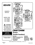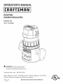
1
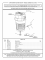
PERATOR'S
MANUAL
T
®
ROUTER
DOUBLE iNSULATED
Model No.
315.175342
0
A
WARNING:
To reduce the risk of injury,
the user must read and understand the
operator's manual before using this product.
Customer
Help Line: 1-800-932-3188
Sears, Roebuck and Co., 3333 Beverly Rd., Hoffman
Visit the Craftsman web page: www.sears.com/craftsman
983000-746
4-05
Save this
manual
Estates, IL 60179 USA
for future
reference
[] Warranty ..........................................................................................................................................................................
2
[] Introduction .....................................................................................................................................................................
2
[] General Safety Rules ....................................................................................................................................................
3-4
[] Specific Safety Rules .......................................................................................................................................................
4
[] Symbols ........................................................................................................................................................................
5-6
[] Electrical ..........................................................................................................................................................................
7
[] Features ...........................................................................................................................................................................
8
[] Assembly .........................................................................................................................................................................
9
[] Operation ....................................................................................................................................................................
9-18
[] Maintenance ..................................................................................................................................................................
19
[] Accessories ...................................................................................................................................................................
20
[] Exploded View and Parts List ........................................................................................................................................
21
[] Parts Ordering/Service
.....................................................................................................................................
FULL ONE YEAR WARRANTY
ON CRAFTSMAN
Back Page
TOOL
If this CRAFTSMAN
tool fails to give complete satisfaction within one year from the date of purchase, RETURN IT TO
THE NEAREST SEARS STORE OR SEARS SERVICE CENTER IN THE UNITED STATES, and Sears will repair it, free
of charge.
If this CRAFTSMAN
of purchase.
tool is used for commercial
or rental purposes, this warranty applies for only 90 days from the date
This warranty gives you specific legal rights, and you may also have other rights which vary from state to state.
Sears, Roebuck and Co., Dept. 817WA, Hoffman Estates, IL 60179
This tool has many features for making its use more pleasant and enjoyable. Safety, performance,
have been given top priority in the design of this product making it easy to maintain and operate.
and dependability
A
WARNING:
Read and understand all instructions. Failure to follow all instructions listed below,
may result in electric shock, fire and/or serious
personal injury.
SAVE THESE
WORK
INSTRUCTIONS
AREA
[] Keep your work area clean and well lit. Cluttered
benches and dark areas invite accidents.
[] Do not operate power tools in explosive atmospheres, such as in the presence of flammable liquids, gases, or dust. Power tools create sparks which
may ignite the dust or fumes.
[] Keep bystanders, children, and visitors away while
operating a power tool. Distractions can cause you to
lose control.
ELECTRICAL
SAFETY
[] Double insulated tools are equipped with a polarized plug (one blade is wider than the other). This
plug will fit in a polarized outlet only one way. If the
plug does not fit fully in the outlet, reverse the plug.
If it still does not fit, contact a qualified electrician
to install a polarized outlet. Do not change the plug
in any way. Double insulation [] eliminates the need
for the three-wire grounded power cord and grounded
power supply system.
[] Avoid body contact with grounded surfaces such
as pipes, radiators, ranges, and refrigerators. There
is an increased risk of electric shock if your body is
grounded.
[] Don't expose power tools to rain or wet conditions.
Water entering a power tool will increase the risk of
electric shock.
[] Do not abuse the cord. Never use the cord to carry
the tools or pull the plug from an outlet. Keep cord
away from heat, oil, sharp edges, or moving parts.
Replace damaged cords immediately. Damaged
cords increase the risk of electric shock.
[] When operating a power tool outside, use an outdoor
extension cord marked "W=A" or "W". These cords
are rated for outdoor use and reduce the risk of electric
shock.
PERSONAL
SAFETY
[] Stay alert, watch what you are doing and use common sense when operating a power tool. Do not
use tool while tired or under the influence of drugs,
alcohol, or medication. A moment of inattention while
operating power tools may result in serious personal
injury.
[] Dress properly. Do not wear loose clothing or
jewelry. Contain long hair. Keep your hair, clothing,
and gloves away from moving parts. Loose clothes,
jewelry, or long hair can be caught in moving parts.
[] Avoid accidental starting. Be sure switch is off
before plugging in. Carrying tools with your finger on
the switch or plugging in tools that have the switch on
invites accidents.
[] Remove adjusting keys or wrenches before turning
the tool on. A wrench or a key that is left attached to a
rotating part of the tool may result in personal injury.
[] Do not overreach. Keep proper footing and balance
at all times. Proper footing and balance enables better
control of the tool in unexpected situations.
[] Use safety equipment. Always wear eye protection.
Dust mask, nonskid safety shoes, hard hat, or hearing
protection must be used for appropriate conditions.
[] Do not wear loose clothing or jewelry. Contain long
hair. Loose clothes, jewelry, or long hair can be drawn
into air vents.
[] Do not use on a ladder or unstable support. Stable
footing on a solid surface enables better control of the
tool in unexpected situations.
TOOL USE AND
CARE
[] Use clamps or other practical way to secure and
support the workpiece to a stable platform. Holding
the work by hand or against your body is unstable and
may lead to loss of control.
[] Do not force tool. Use the correct tool for your application. The correct tool will do the job better and
safer at the rate for which it is designed.
[] Do not use tool if switch does not turn it on or off.
Any tool that cannot be controlled with the switch is
dangerous and must be repaired.
[] Disconnect the plug from power source before
making any adjustments,
changing accessories,
or storing the tool. Such preventive safety measures
reduce the risk of starting the tool accidentally.
[] Store idle tools out of the reach of children and
other untrained persons. Tools are dangerous in the
hands of untrained users.
[] Maintain tools with care. Keep cutting tools sharp
and clean. Properly maintained tools with sharp cutting edges are less likely to bind and are easier to
control.
[] Check for misalignment
or binding of moving parts,
breakage of parts, and any other condition that
may affect the tool's operation, if damaged, have
the tool serviced before using. Many accidents are
caused by poorly maintained tools.
[] Use only accessories that are recommended
by the
manufacturer for your model. Accessories that may
be suitable for one tool, may become hazardous when
used on another tool.
[] Keep the tool and its handle dry, clean and free
from oil and grease. Always use a clean cloth when
cleaning. Never use brake fluids, gasoline, petroleumbased products, or any strong solvents to clean your
tool. Following this rule will reduce the risk of loss of
control and deterioration of the enclosure plastic.
SERVICE
[] Tool service must be performed only by qualified
repair personnel. Service or maintenance performed
by unqualified personnel may result in a risk of injury.
[] Hold tool by insulated gripping surfaces when
performing an operation where the cutting tool may
contact hidden wiring or its own cord. Contact with
a "live" wire will make exposed metal parts of the cutting tool "live" and shock the operator.
[] Know your power tool. Read operator's manual
carefully. Learn its applications and limitations, as
well as the specific potential hazards related to this
tool. Following this rule will reduce the risk of electric
shock, fire, or serious injury.
[] Always wear safety glasses. Everyday eyeglasses
have only impact-resistant lenses; they are NOT
safety glasses. Following this rule will reduce the risk
of serious personal injury.
[] Protect your lungs. Wear a face or dust mask if the
operation is dusty. Following this rule will reduce the
risk of serious personal injury.
[] Protect your hearing. Wear hearing protection during extended periods of operation. Following this rule
will reduce the risk of serious personal injury.
[] Inspect tool cords periodically and, if damaged,
have repaired at your nearest Authorized Service
Center. Constantly stay aware of cord location.
Following this rule will reduce the risk of electric shock
or fire.
[] When servicing a tool, use only identical replacemerit parts. Follow instructions in the Maintenance
section of this manual. Use of unauthorized parts or
failure to follow Maintenance Instructions may create a
risk of shock or injury.
be carefully checked to determine that it will operate properly and perform its intended function.
Check for alignment of moving parts, binding of
moving parts, breakage of parts, mounting, and
any other conditions that may affect its operation. A guard or other part that is damaged should
be properly repaired or replaced by an authorized
service center. Following this rule will reduce the risk
of shock, fire, or serious injury.
[] Make sure your extension cord is in good condition.
When using an extension cord, be sure to use one
heavy enough to carry the current your product will
draw. A wire gauge size (A.W.G.) of at least 14 is
recommended for an extension cord 50 feet or less
in length. A cord exceeding 100 feet is not recommended. If in doubt, use the next heavier gauge.
The smaller the gauge number, the heavier the
cord. An undersized cord will cause a drop in line voltage resulting in loss of power and overheating.
[] Inspect for and remove all nails from lumber before
using this tool. Following this rule will reduce the risk
of serious personal injury.
[] Save these instructions. Refer to them frequently and
use them to instruct others who may use this tool. If
you loan someone this tool, loan them these instructions also.
[] Check damaged parts. Before further use of the
tool, a guard or other part that is damaged should
_1_ WARNING:
Some dust created by power sanding, sawing, grinding, drilling, and other construction
contains chemicals known to cause cancer, birth defects or other reproductive
chemicals are:
• lead from lead-based paints,
activities
harm. Some examples of these
crystalline silica from bricks and cement and other masonry products, and
arsenic and chromium from chemically-treated
lumber.
Your risk from these exposures varies, depending on how often you do this type of work. To reduce your exposure
to these chemicals: work in a well ventilated area, and work with approved safety equipment, such as those dust
masks that are specially designed to filter out microscopic particles.
Someofthefollowingsymbolsmaybeusedonthistool.Pleasestudythemandlearntheirmeaning.Properinterpretationofthesesymbolswillallowyouto operatethetoolbetterandsafer.
SYMBOL
NAME
DESIGNATION/EXPLANATION
V
Volts
Voltage
A
Am pe res
Current
Hz
Hertz
Frequency (cycles per second)
W
Watt
Power
Minutes
Time
Alternating Current
Type of current
Direct Current
Type or a characteristic
no
No Load Speed
Rotational speed, at no load
[]
Class II Construction
Double-insulated
.../min
Per Minute
Revolutions, strokes, surface speed, orbits etc., per minute
@
Wet Conditions Alert
Do not expose to rain or use in damp locations.
Read The Operator's Manual
To reduce the risk of injury, user must read and understand
operator's manual before using this product.
Eye Protection
Always wear safety goggles, safety glasses with side shields, or
a full face shield when operating this product.
Safety Alert
Precautions that involve your safety.
No Hands Symbol
Failure to keep your hands away from the blade will result in
serious personal injury.
No Hands Symbol
Failure to keep your hands away from the blade will result in
serious personal injury.
No Hands Symbol
Failure to keep your hands away from the blade will result in
serious personal injury.
No Hands Symbol
Failure to keep your hands away from the blade will result in
serious personal injury.
Hot Surface
To reduce the risk of injury or damage, avoid contact with
any hot surface.
min
0
@
@
@
®
of current
construction
Thefollowingsignalwordsandmeanings
areintendedto explainthe levelsofriskassociated
withthis
product.
SYMBOL
SIGNAL
MEANING
DANGER:
Indicates an imminently hazardous situation, which, if not avoided, will
result in death or serious injury.
WARNING:
Indicates a potentially hazardous situation, which, if not avoided, could
result in death or serious injury.
CAUTION:
Indicates
a potentially
hazardous
result
in minor
or moderate
injury. situation, which, if not avoided, may
CAUTION:
(Without Safety Alert Symbol) Indicates a situation that may result in
property damage.
SERVICE
Servicing requires extreme care and knowledge and
should be performed only by a qualified service technician. For service we suggest you return the product to
your nearest AUTHORIZED SERVICE CENTER for repair.
When servicing, use only identical replacement parts.
,_
A
WARNING;
To avoid serious personal injury, do not
attempt to use this product until you read thoroughly
and understand completely the operator's manual.
Save this operator's manual and review frequently for
continuing safe operation and instructing others who
may use this product.
WARNING"
The operation of any power tool can result in foreign objects being thrown into your eyes, which
can result in severe eye damage. Before beginning power tool operation, always wear safety
goggles, safety glasses with side shields, or a full face shield when needed. We recommend Wide
Vision Safety Mask for use over eyeglasses or standard safety glasses with side shields.
Always use eye protection which is marked to comply with ANSI Z87.1.
SAVE THESE INSTRUCTIONS
DOUBLE
INSULATION
Double insulation is a concept in safety in electric power
tools, which eliminates the need for the usual three-wire
grounded power cord. All exposed metal parts are
isolated from the internal metal motor components with
protecting insulation. Double insulated tools do not need
to be grounded.
A
WARNING:
The double insulated system is
intended to protect the user from shock resulting
from a break in the tool's internal insulation. Observe
all normal safety precautions to avoid electrical
shock.
NOTE: Servicing of a tool with double insulation requires
extreme care and knowledge of the system and should
be performed only by a qualified service technician. For
service, we suggest you return the tool to your nearest
authorized service center for repair. Always use original
factory replacement parts when servicing.
ELECTRICAL
CONNECTION
This tool has a precision-built electric motor. It should be
connected to a power supply that is 120 volts, 60 Hz,
AO only (normal household current}. Do not operate
this tool on direct current (DC). A substantial voltage drop
will cause a loss of power and the motor will overheat. If
your tool does not operate when plugged into an outlet,
double-check the power supply.
EXTENSION
CORDS
When using a power tool at a considerable distance from
a power source, be sure to use an extension cord that has
the capacity to handle the current the tool will draw. An
undersized cord will cause a drop in line voltage, resulting
in overheating and loss of power. Use the chart to determine the minimum wire size required in an extension cord.
Only round jacketed cords listed by Underwriter's Laboratories (UL) should be used.
When working outdoors with a tool, use an extension
cord that is designed for outside use. This type of cord is
designated with "WA" on the cord's jacket.
Before using any extension cord, inspect it for loose or
exposed wires and cut or worn insulation.
**Ampere rating
(on tool faceplate)
0-2.0
2.1-3.4 3.5-5.0 5.1-7.0 7.1-12.0 12.1-16.0
Cord Length
Wire Size (A.W.G.)
25'
16
16
16
16
14
14
50'
16
16
16
14
14
12
100'
16
16
14
12
10
--
**Used on 12 gauge - 20 amp circuit
NOTE: AWG = American Wire Gauge
A
A
WARNING:
Keep the extension cord clear of the
working area. Position the cord so that it will not get
caught on lumber, tools or other obstructions while
you are working with a power tool. Failure to do so
can result in serious personal injury.
WARNING:
Check extension cords before each
use. If damaged replace immediately. Never use tool
with a damaged cord since touching the damaged
area could cause electrical shock resulting in serious
injury.
PRODUCTSPECIFICATIONS
......................................................................
2
DepthofCut............................................................
1-1/2in. Horsepower
NoLoadSpeed
...............................................
25,000/rain.
Depthof Plunge
.............................................................
2 in.
Collet..........................................................................
1/4in. Input................................
120V,60Hz,AConly9.5Amps
NetWeight.............................................................
5.06Ibs.
MOTOR
HOUSING
TOGGLE
SWITCH
SPINDLELOCK
BUTTON
Fig. 1
KNOW
YOUR ROUTER
SPINDLE
See Figure 1,
Before attempting to use this product, familiarize yourself
with all operating features and safety rules.
TOGGLE
SWITCH
The router has a conveniently
located toggle switch.
LOCK
BUTTON
The spindle lock secures the spindle while you make adjustments and acts as a retainer to keep the router body
from coming out of the base.
UNPACKING
This product has been shipped completely assembled.
[] Carefully remove the tool and any accessories from the
box. Make sure that all items listed in the packing list
are included.
[] Inspect the tool carefully to make sure no breakage or
damage occurred during shipping.
,_
A
[] Do not discard the packing material until you have
carefully inspected and satisfactorily operated the tool.
[] If any parts are damaged or missing, please call
1-800-932-3188 for assistance.
PACKING
A
LiST
Router with Fixed Base
Plunge Base
Toolbag
Dust Nozzle with Screws (#6-32 x 3/8 in.)
Wrench
Operator's Manual
_11_ WARNING:
Do not allow familiarity with tools
to make you careless. Remember that a careless
fraction of a second is sufficient to inflict serious
injury.
A
A
A
A
WARNING;
If any parts are missing do not operate
this tool until the missing parts are replaced. Failure
to do so could result in possible serious personal
injury.
WARNING:
Do not attempt to modify this tool
or create accessories not recommended for use
with this tool. Any such alteration or modification is
misuse and could result in a hazardous condition
leading to possible serious personal injury.
WARNING:
Do not connect to power supply until
assembly is complete. Failure to comply could result
in accidental starting and possible serious injury.
WARNING:
Never attempt to use the router motor without first installing it in one of the approved
bases. Failure to heed this warning could result in
personal injury and damage to the motor.
WARNING;
Always wear safety goggles or safety
glasses with side shields when operating power
tools. Failure to do so could result in objects being
thrown into your eyes resulting in possible serious
injury.
SWITCHING
BASE
WARNING:
Do not use any attachments or accessories not recommended by the manufacturer of
this tool. The use of attachments or accessories not
recommended can result in serious personal injury.
[] Place the router upside down with the Craftsman label
away from you.
WARNING:
Never attempt to use the router motor without first installing it in one of the approved
bases. Failure to heed this warning could result in
personal injury and damage to the motor.
APPLICATIONS
[] Rout grooves, carve designs, mortise door jambs, or
create joints
[] Cabinet making, routing counter tops, and finishing
work
FROM FIXED BASE TO PLUNGE
See Figures 2 - 3,
To remove the fixed base:
[] Unplug the router.
[] Loosen the locking arm on the base.
[] Depress and hold the spindle lock button. The spindle
lock button will not depress fully unless it is in line with
the hole in the collet.
[] If the spindle lock button does not depress fully, turn
the collet nut while depressing the spindle lock button.
As they align, the spindle lock button will depress fully.
[] Turn the depth adjusting ring counterclockwise
the motor is at its highest position.
until
[] Align the indicator arrow on the depth adjustment ring
with the indicator point on the base.
[] Pull the base until it dislodges from the motor housing.
Use caution as this may result in permanent damage to
the locking mechanism.
Toinstallthe plungebase:
[] Unplugthe router.
[] Placetheplungebaseona fiatsurface.
[] Loosenthelockingknob.
[] Alignthegrooveinthe motorhousingwiththerib
insidethe base.
NOTE:Therib is locatedonthe insideof thebasein
linewiththehandle.
[] Depressandholdthespindlelockbutton.
[] Slidethe motorhousingintothebase.
[] Tightenthe lockingknob.
GROOVE
INMOTOR
HOUSING
LOCKING
KNOB
CAUTION:Donottightenthe lockingknobwithout
the motorinstalledinthebase.Failureto heedthis
warningcouldcauseseriousinjury.
RiBINSIDE
BASE
Fig. 3
SWITCHING
FROM
PLUNGE
BASE TO FIXED
BASE
SPINDLE LOCK
BUTTON
See Figures 4 - 6.
To remove the plunge base:
[] Unplug the router.
[] Place the router on a fiat surface.
ARM
[] Loosen the locking knob.
[] Depress and hold the spindle lock button. The spindle
lock button will not depress fully unless it is in line with
the hole in the collet.
[] If the spindle lock button does not depress fully, turn
the collet nut while depressing the spindle lock button.
When aligned, the spindle lock button will depress fully.
DEPTH ADJUSTMENT
RING
[] Remove the motor housing from the plunge base.
INDICATOR
ARROW
_i_
NOTE: When removing the motor from the base, the
spindle lock button must be depressed until it clears
the opening beneath the base.
DEPTH
ADJUSTMENT
RING
INDICATORPOINT
Fig. 2
10
TO INSTALL
THE FIXED BASE
See Figures 4 - 6,
[] Unplug the router.
[] Place the fixed base on a flat surface.
[] Loosen the locking arm.
[] Align the indicator arrow on the depth adjustment ring
with the indicator point on the base.
[] Align the groove in the motor housing with the tab
inside of the base.
NOTE: The tab is located on the inside of the base in
line with the handle.
[] Depress and hold the spindle lock button on the motor.
[] Slide the motor housing into the base.
TABiNSiDE
BASE
[] Turn the depth adjusting ring counterclockwise until
the spindle lock snaps out as it clears the rear window,
just below the locking arm.
[] Tighten the locking arm.
DEPTH
ADJUSTMENT
RING
LOCKING
KNOB
Fig. 5
INDICATOR
ARROW
DEPTH
ADJUSTMENT
RING
INDICATORPOINT
Fig. 6
SPINDLELOCK
BUTTON
Fig. 4
11
A
WARNING:
If the collet nut is not securely tightened, the cutter may detach during use, causing
serious personal injury.
COLLET
NUT
TO LOOSEN
A
WARNING:
Do not use cutters with undersized
shanks. Undersized shanks will not tighten properly
and could be thrown from the tool causing injury.
A
TO
TIGHTEN
WARNING:
Do not use cutters that are larger in diameter than the opening in router base. Use of such
cutters will come in contact with the router base
and damage both the cutter and router base. This
situation could also cause possible loss of control or
create other hazardous conditions that could cause
possible serious personal injury.
CAUTION: To prevent damage to the spindle or
spindle lock, always allow motor to come to a complete stop before engaging the spindle lock.
Fig. 7
[] Unplug the router.
To insert the cutter/bit:
SELECTING
DEPTH OF CUT
Proper depth of cut depends on several factors: the
horsepower of the router motor, the type of cutter / bit,
and the type of wood. A lightweight, low horsepower
router is designed for making shallow cuts; a router with
higher horsepower is designed for deeper cuts. Small cutters, such as veining cutters with 1/16 in. cutting diameters, are designed to remove only small amounts of wood.
Large cutters, such as straight-flute cutters, remove larger
amounts of wood and make deeper cuts in soft woods,
such as white pine.
[] Depress and hold the spindle lock button.
[] Insert the shank of the cutter until the shank bottoms
out, then pull it out 1/16 in. to allow for expansion
when the cutter gets hot.
Choose a depth of cut that will not place excessive strain
on the router motor. If you need extra force or the motor
speed slows down considerably, turn off the router and
reduce the depth of cut. Then, make the cut in two or
more passes.
A
WARNING:
If you are changing a cutter immediately after use, be careful not to touch the cutter nut,
cutter, or collet with your hands or fingers. They will
get burned because of the heat buildup from cutting.
Always use the wrench provided.
INSERTING
/ REMOVING
CUTTERS
/ BITS
See Figure 7.
[] Tighten the collet nut securely by turning it clockwise
with the wrench provided.
[] Release the spindle lock button.
To remove the cutter/bit:
When routing a groove that is too deep to safely cut in
one pass, make the cut in several passes. We recommend
that cuts be made at a depth not exceeding 1/8 in. and
that several passes be made to reach deeper cuts.
[] Lay the router down on a workbench to gain access to
the collet nut.
Adjusting the depth of cut for the plunge router is different
from adjusting the depth of cut for the fixed router.
[] Loosen the locking knob on the plunge base or the
locking arm on the fixed base.
[] Depress and hold the spindle lock button.
[] Loosen the collet nut by turning it counterclockwise
with the wrench provided.
12
ADJUSTING
DEPTH
OF CUT FOR PLUNGE
BASE
DEPTH
INDICATOR
ROUTERS
See Figures 8 - 10.
[] Unplug the router.
[] Place the plunge base on a flat surface.
[] Loosen the stop bar knob.
(
[] Unlock the plunge lock lever.
[] Plunge the router until the tip of the cutter touches the
flat surface.
[] Lock the plunge lock lever.
[] Move the stop bar down so that it touches the depth
stop.
[] Tighten the stop bar knob securely.
Fig. 9
[] Set the depth indicator to zero.
[] Loosen the stop bar knob.
[] Tighten the stop bar knob securely.
[] Set the depth indicator to the desired depth of cut.
NOTE: Each mark on the scale indicates 1/16 in.
[] Unlock the plunge lock lever.
[] Position the router so that the cutter can extend below
the subbase for desired depth of cut.
[] Plunge the router until the stop bar touches the depth
stop.
PLUNGELOCK
LEVER
[] Lock the plunge lock lever to position the cutter at the
desired depth of cut. Tighten the stop bar knob securely.
STOP
BAR
KNOB
STOPBAR
CUTTER
Fig. 8
Fig. 10
13
ADJUSTING
DEPTH
OF CUT FOR FIXED BASE
ROUTERS
See Figures 11 - 13.
[] Unplug the router.
[] Place the fixed base on a flat surface.
[] Loosen the locking arm.
[] Turn the depth adjustment ring counterclockwise
the tip of the cutter touches the work surface.
until
[] Turn the depth indicator ring until the zero lines up with
the indicator point on the base.
Fig. 13
TURNING
THE ROUTER
ON AND OFF
See Figure 14.
To turn the router on, push the switch to the (I) or on
position. Return the switch to the ( 0 ) or off position
when routing operation is finished.
LOCKINGARM
Fig. 11
[] Position the router so that the cutter can extend below
the subbase for desired depth of cut.
ON
[] Turn the depth adjustment ring to the desired depth of
cut.
OFF
[] Tighten the locking arm securely.
NOTE- To adjust the depth of cut when the router is
mounted to a router table, turn the depth adjustment
ring until the cutter reaches the desired depth of cut.
Fig. 14
INDICATOR
POINT
INDICATOR
RING
Fig. 12
14
Fig.15
,_
Fig. 16
WARNING:
Cutter continues to rotate after the
router has been turned off. To avoid injury, wait until
the cutter has come to a complete stop before removing router from the workpiece.
OPERATING
_lk
THE ROUTER
See Figures 15- 16.
When routing straight cuts across stock, clamp a straight
edge to the workpiece to use as a guide. Position the
straight edge parallel to the line of cut and offset the
distance between the cutting edge of the cutter and the
edge of the router base. Hold the router base against the
straight edge and rout the groove.
FREEHAND
ROUTING
See Figure 15.
When used freehand, your router becomes a flexible and
versatile tool. This flexibility makes it possible to easily
rout signs, relief sculptures, etc. When freehand routing,
we suggest the following:
When routing a groove wider than the diameter of the cutter, clamp a straight edge on both sides of the cut lines.
Position both guides parallel to the desired line of cut and
spacedequal distances from the desired edges of the
groove. Rout along one guide then reverse direction and
rout along the other guide. Clean out any remaining waste
in the center of the groove.
[] Draw or layout the pattern on the workpiece.
[] Choose the appropriate cutter.
NOTE: A core box or V-groove cutter is often used for
routing letters and engraving objects. Straight cutters
and ball mills are often used to make relief carvings.
Veining cutters are used to carve small, intricate details.
EDGE ROUTING
[] Place the router on the edge of the workpiece without
the cutter contacting the workpiece.
[] Rout the pattern in two or more passes. Make the first
pass at 25% of the desired depth of cut. This will provide better control as well as being a guide for the next
pass.
[] Turn router on and let the motor build up to full speed.
[] Gradually feed the cutter into the workpiece.
[] Upon completion of the cut, turn the router off and let
the cutter come to a complete stop before removing
the router from the workpiece.
INTERNAL
WARNING:
Do not use large router cutter for freehand routing. Use of large router bits when freehand
routing could cause loss of control or create other
hazardous conditions that could result in personal
injury, if using a router table, large cutters should be
used for edging only. Do not, for any purpose, use
cutters that are larger in diameter than the opening in
the router base.
NOTE: Do not rout deeper than 1/8 in. per pass.
ROUTING
[] Tilt router and place on workpiece without the cutter
contacting the workpiece.
[] Turn the router on and let the motor build up to full
speed.
[] Gradually feed cutter into the workpiece until the subbase is level with the workpiece.
[] Upon completion of the cut, turn the router off and let
the cutter come to a complete stop before removing
the router from the workpiece.
15
EDGINGWITH PILOT CUTTERS/
BITS
DIRECTION
OF FEED AND THRUST
See Figure 17.
See Figures 18- 19.
The arbor-type bits with pilots are excellent for quick,
easy, edge shaping of any workpiece edge that is either
straight or curved at a curvature as great or greater than
the radius of the bit to be used. The pilot prevents the bit
from making too deep a cut; and holding the pilot firmly in
contact with the workpiece edge throughout prevents the
cut from becoming too shallow.
The router motor and cutter revolve in a clockwise direction. This gives the tool a slight tendency to twist in a
counterclockwise direction, especially when the motor
revs up.
Feed the router into the workpiece from left to right. When
fed from left to right, the rotation of the cutter pulls the
router against the workpiece. If fed in the opposite direction, the rotation of the spinning cutter will tend to throw
the router away from the workpiece causing kickback.
This could cause you to lose control of the router.
Whenever the workpiece thickness together with the
desired depth of cut (as adjusted by router depth setting) are such that only the top part of the edge is to be
shaped (leaving at least a 1/16 inch thick uncut portion
at bottom), the pilot can ride against the uncut portion,
which will serve to guide it. However, if the workpiece is
too thin or the bit set too low so that there will be no uncut
Because of the high speed of cutter rotation during a
proper feeding operation, there is very little kickback
under normal conditions. However, if the cutter strikes a
knot, hard grain, or foreign object that affects the normal
progress of the cutting action, there will be a slight kickback. The direction of kickback is always in the direction
opposite cutter rotation. This will affect the trueness of
your cut.
edge to ride the pilot against, an extra board to act as a
guide must be placed under the workpiece. This "guide"
board must have exactly the same contour-- straight or
curved--as the workpiece edge. If it is positioned so that
its edge is flush with the workpiece edge, the bit will make
a full cut (in as far as the bit radius). On the other hand,
if the guide is positioned as shown in Figure 13 (out from
the workpiece edge), the bit will make less than a full cut
-- which will alter the shape of the finished edge.
To guard against kickback, plan your setup and direction of feed so that you will always be thrusting the tool in
the same direction that the leading edge of the cutter is
moving. The thrust should be in a direction that keeps the
sharp edges of the cutter continuously biting straight into
new (uncut) wood.
NOTE: Any of the piloted bits can be used without a pilot
for edge shaping with guides, as preceding. The size
(diameter) of the pilot that is used determines the maximum cut width that can be made with the pilot against the
workpiece edge (the small pilot exposes all of the bit; the
large one reduces this amount by 1/16 in.).
NOTE: For best results, make sure to take enough time to
set up for cutting. While cutting, make sure to use the proper
rate of feed.
CUTTING
PILOT
Fig. 18
TOPEDGESHAPING
II .°°,,. l lwo.,
II
PIL
WHOLE EDGESHAPING
Fig. 17
16
Whenroutinga groove,yourtravelshouldbeina directionthatplacestheguideyouareusingatthe right-hand
side.Whentheguideis positionedasshowninthe "guide
inside"illustration,
tooltravelshouldbefromleftto right
andcounterclockwise
aroundcurves.Whentheguide
is positionedasshowninthe "guideoutside"illustration,tooltravelshouldbefromrightto leftandclockwise
aroundcurves.Ifthereis a choice,thefirstsetupisgenerallythe easierto use.Ineithercase,thesidewaysthrust
youuseis againsttheguide.
[] Check the progress of each cut. Too slow feeding can
cause the router to take off in a wrong direction from
the intended line of cut. Force feeding increases the
strain of holding the tool and results in loss of speed.
[] Notice the chips being produced as you cut. If the
router is fed too slowly, it will scorch or burn the wood.
If fed too fast, it will take large chips out of the wood
and leave gouge marks.
Test a cut on a scrap piece of the workpiece before you
begin. Always grasp and hold the router firmly with both
hands.
GUIDEiNSiDE
If you are making a small diameter, shallow groove in soft,
dry wood, the proper feed rate may be determined by the
speed at which you can travel the router along the guide
line. If the cutter is a large one, the cut is deep, or the
workpiece is hard to cut, the proper feed may be a very
slow one. A cross grain cut may require a slower pace
than an identical with grain cut in the same workpiece.
ROTATION _._
_THRUST
ROTATION _.___
FEED
GUIDEOUTSIDE
!
ROTATION _at,,,_ \ I
THRUSTK
)_'11 J
TOOFAST
Fig. 20
FEEDING
FEED
See Figure 20,
GUIDE
Clean, smooth routing and edge shaping can be done
only when the cutter is revolving at a relatively high speed
and is taking very small bites to produce tiny, cleanly
severed chips. If you force the router to move forward too
fast, the RPM of the cutter becomes slower than normal
in relation to its forward movement. As a result, the cutter
must take bigger bites as it revolves. Bigger bites mean
bigger chips and a rougher finish. Also, because bigger
bites require more power, the router motor may become
overloaded.
Fig. 19
PROPER
TOO FAST
RATE OF FEED
Professional routing depends upon careful setup and
proper rate of feed which is learned through practice and
use. The proper rate of feed is dependent upon:
[] hardness and moisture content of the workpiece
[] depth of cut
[] cutting diameter of the cutter
Under extreme force-feeding conditions, the relative
RPM of the cutter can become so slow--and the bites it
When cutting shallow grooves in soft woods such as pine,
a faster rate of feed can be used. When making cuts in
hardwoods such as oak, a slower rate of feed is required.
has to take so large--that chips will be partially knocked
off (rather than fully cut off). This causes splintering and
gouging of the workpiece.
Several factors will help you select the proper rate of feed.
[] Choose the rate that does not slow down the motor.
The router is an extremely high-speed tool, and will make
clean, smooth cuts if allowed to run freely without the
overload of a forced feed. You can always detect force
feeding by the sound of the motor. Its high-pitched whine
will sound lower and stronger as it loses speed. Also, the
strain of holding the tool will be noticeably increased.
[] Choose the rate at which the cutter advances firmly
and surely to produce a continuous spiral of uniform
chips or a smooth edge.
[] Listen to the sound of the motor. A high-pitched sound
means you are feeding too slowly. A strained, lower
pitched sound signals force feeding.
17
FEEDINGTOOSLOW
DEPTH
See Figure 21.
See Figures 22 - 23.
It is possible to spoil a cut by moving the router forward
too slowly. When you advance the router into the work too
slowly, the revolving cutter does not dig into new wood
fast enough to take a bite; instead, it merely scrapes away
sawdust-like particles. Scraping produces heat, which
can glaze, burn, or mar the cut and in extreme cases, can
overheat the cutter, destroying its hardness.
Depth of cut is important because it affects the rate of
feed that, in turn, affects the quality of the cut and the
possibility of damage to the tool's motor and cutter.
OF CUT
DEPTH
_Z2T
F
When the cutter is scraping instead of cutting, controlling
the router is more difficult. With practically no load on the
motor, the cutter revolves at close to top RPM, and has
a much greater than normal tendency to bounce off the
sides of the cut (especially if the wood has a pronounced
grain with hard and soft areas). As a result, the cut produced may have rippled, instead of straight, sides.
i'd--WiDTH OF CUT
Fig. 22
A deep cut requires a slower feed than a shallow one. A
cut that is too deep will slow the feed so that the cutter
is scraping rather than cutting. A too deep cut can cause
smaller cutters to be broken off. Cutters that are 1/16 in.
in diameter are easily broken off when subjected to too
much side thrust. A large enough cutter is not likely to
break, but attempting a cut that is too deep may result
in a rough cut, and it may be difficult to guide and control the cutter as desired. It is recommended that you do
not exceed 1/8 in. depth of cut in a single pass, regardless of the cutter size or the softness or condition of the
workpiece.
2ND
PASS
TOOSLOW
Fig. 21
Feeding too slowly can also cause the router to take off in a
wrong direction from the intended line of cut. Always grasp
and hold the router firmly with both hands when routing.
p2AINsIDs
r_i
;ASsTs
IST
You can detect when you are feeding the router too slowly by
the runaway, high-pitched sound of the motor or by feeling
the wiggle of the cutter in the cut.
Fig. 23
To make deeper cuts, make as many successive passes
as needed, lowering the cutter 1/8 in. for each new pass.
To save time, perform all the cutting necessary at one
depth setting before lowering the cutter for the next pass.
This will insure a uniform depth when you complete the
final pass.
NOTE: Do not remove more than 1/8 in. in a single pass.
Excessive depth of cut can result in loss of control and the
possibility of serious personal injury.
18
A
A
CLEANING
WARNING:
When servicing, use only identical
Craftsman replacement parts. Use of any other parts
may create a hazard or cause product damage.
Get faster more accurate cutting results by keeping cutters clean and sharp. Remove all accumulated pitch and
gum from cutters after each use. When sharpening cutters, sharpen only the inside of the cutting edge. Never
grind the outside diameter. Be sure when sharpening the
end of a cutter to grind the clearance angle the same as
originally ground.
WARNING:
Always wear safety goggles or safety
glasses with side shields during power tool operation
or when blowing dust. If operation is dusty, also wear
a dust mask.
CLEANING
GENERAL
MAINTENANCE
WARNING"
THE COLLET
From time to time, it also becomes necessary to clean the
collet and collet nut. To do so, simply remove collet nut
from collet and clean the dust and chips that have collected. Then return collet nut to its original position.
Avoid using solvents when cleaning plastic parts. Most
plastics are susceptible to damage from various types of
commercial solvents and may be damaged by their use.
Use clean cloths to remove dirt, dust, oil, grease, etc.
,_
THE CUTTERS
ADJUSTING
FIXED
Do not at any time let brake fluids,
LOCKING
ARM TENSION
ON THE
BASE ROUTER
Over time and with repeated use, the locking arm may
become loose. When this occurs, tighten the elastic stop
nut slightly. The elastic stop nut should be loose enough
so there is some play in the locking arm when it is in the
open position. Make sure the motor housing does not
move up or down when clamped.
gasoline, petroleum-based products, penetrating
oils, etc., come in contact with plastic parts. Chemicals can damage, weaken or destroy plastic which
may result in serious personal injury.
Electric tools used on fiberglass material, wallboard,
spackling compounds, or plaster are subject to accelerated wear and possible premature failure because the
fiberglass chips and grindings are highly abrasive to bearings, brushes, commutators, etc. Consequently, we do not
recommended using this tool for extended work on these
types of materials. However, if you do work with any of
these materials, it is extremely important to clean the tool
using compressed air.
NOTE: Do not over tighten the elastic stop nut. The locking arm should clamp tightly to secure the motor housing.
If the locking arm becomes worn beyond adjustment, a
repair kit is available. Please contact your service center
to order the appropriate router locking arm repair kit.
LUBRICATION
All of the bearings in this tool are lubricated with a sufficient amount of high grade lubricant for the life of the unit
under normal operating conditions. Therefore, no further
lubrication is required.
Only the parts shown on the parts list are intended to be
repaired or replaced by the customer. All other parts
should be replaced at a Sears Service Center.
19
Lookfortheseaccessories
atSearsretail:
[] D-HandleBase
[] DovetailTemplate
[] ButtHinge
[] DovetailTemplate
Rout-A-Form
Pantograph
[] ButtHingeTemplate
Set
[] Multi-Purpose
RouterGuideTemplate
GuideBushing
!ii_iiii iiiiiiiiiiii iiiiiiiiiiiiiiiiiiiiiiiiiiiiiii iiiiiii iiiiiiiiiiiiiiiiiiiiiiiiiiiiiii iiiiiiiiiiiiiiiiiiiiiiiiiiiiiii iiiiiiiiiiiiiiiiiiiiiiiiiiiiiii iiiiiiiiiiiiiiiiiiiiiiiiiiiiiii iiiiiiiiiiiiiiiiiiiiiiiiiiiiiii iiiiiiiiiiiiiiiiiiiiiiiiiiiiiii iiiiiii iiiiiiiiiiiiiiiiiiiiiiiiiiiiiii iiiiiiiiiiiiiiiiiiiiiiiiiiiiiii iiiiiiiiiiiiiiiiiiiiiiiiiiiiiii iiiiiiiiiiiiiiiiiiiiiiiiiiiiiii iiiiiiiiiiiiiiiiiiiiiiiiiiiiiii iiiiiiiiiiiiiiiiiiiiiiiiiiiiiii iiiiiii iiiiiiiiiiiiiiiiiiiiiiiiiiiiiii iiiiiiiiiiiiiiiiiiiiiiiiiiiiiii iiiiiiiiiiiiiiiiiiiiiiiiiiiiiii iiiiiiiiiiiiiiiiiiiiiiiiiiiiiii iiiiiiiiiiiiiiiiiiiiiiiiiiiiiii iiiiiiiiiiiiiiiiiiiiiiiiiiiiiii iiiiiii iiiiiiiiiiiiiiiiiiiiiiiiiiiiiii iiiiiiiiiiiiiiiiiiiiiiiiiiiiiii iiiiiiiiiiiiiiiiii
COMBI- VEiNiNG
NATION BiT
PANEL
CUTTER
l
CORE
BOX
BiT
STRAIGHT COMBIHINGE DOVETAILRABBET OGEE,
COVE
BEAD
ARBOR
FACE
NATION MORTiSiNG CUTTER
BiT
ROMAN0
BiT,
QUARTER-WITH BALL
BiT
BiT
BiTS
45°
ROUND BEARINGS
STRAIGHT,
BEVEL
CHAMFER
BIT
2589
CUTTER
BiT
Eli
t
V-GROOVE
CHAMFER
WITH 2
BALL
BEARINGS
(1/2iN.&
5/siN.)
* FOR CARBIDETIPPEDEDGEFORMINGBiTS
* 25895 FORCARBIDETIPPEDEDGEFORMINGBiTS
*25895
I
2589 FOR HiGHSPEEDSTEELEDGEFORMINGBiTS
,&
A
WARNING:
Current attachments and accessories available for use with this tool are listed above. Do not use anyattachments or accessories not recommended by the manufacturer of this tool. The use of attachments or accessories not recommended can result in serious personal injury.
WARNING:
Only use router tables with proper guarding for the cutter and with on-board switch controller receptacles (Part No. 9-25188). Failure to use router tables with appropriate safety features could result in serious personal
injury.
20
_,
CRAFTSMAN
ROUTER
MOTOR
- MODEL
NUMBER
315.175342
The model number will be found on a plate attached to the motor housing. Always mention the model
number in all correspondence regarding your ROUTER MOTOR or when ordering repair parts,
SEE BACK
PAGE FOR PARTS ORDERING
INSTRUCTIONS
SEENOTE
2
1
4
I
PARTS
Key
No.
PaN
Number
Description
LIST
Qty.
1
690141001
Shaft Lock Spring ............................................................................................
1
2
671457001
Shaft Lock Pin .................................................................................................
1
3
671245001
*E-Ring **STD581018 ......................................................................................
1
4
690190001
Collet Nut ........................................................................................................
1
5
940115101
Data Plate ........................................................................................................
1
6
671250001
Wrench ............................................................................................................
1
983000746
Operator's
Manual
* Standard Hardware
** Available
*** Complete
Note:
assortment
Item - May Be Purchased Locally
From DJv. 98 = Source 980.0
available
at your Nearest Sears Retail Store
The assembly shown represents an important part of the double insulated system. To avoid the
possibility of alteration or damage to the system, service should be performed by your nearest
Sears repair center. Contact your nearest Sears retail store for service center information.
21
Your Home
For repair-in
your home-of all major brand appliances,
lawn and garden equipment, or heating and cooling systems,
no matter who made it, no matter who sold it!
For the replacement parts, accessories and
owner's manuals that you need to do-it-yourself.
For Sears professional installation of home appliances
and items like garage door openers and water heaters.
1-800-4-MY-HOME
Call anytime,
®
(1-800-469-4663)
day or night (U.S.A. and Canada)
www.sears.com
www.sears.ca
Our Home
For repair of carry-in items like vacuums, lawn equipment,
and electronics, call or go on-line for the location of your nearest
Sears Parts & Repair Center.
1-800-488-1222
Call anytime, day or night (U.S.A. only)
www.sears.com
To purchase a protection agreement (U.S.A.)
or maintenance agreement (Canada) on a product serviced by Sears:
1-800-827-6655
(U.S.A.)
1-800-361-6665
Para pedir servicio de reparaci6n
a domicilio, y para ordenar piezas:
1-888-SU-HOGAR
Au Canada
(Canada)
pour service en fran(_ais:
1-800-LE-FOYER
SM
Mc
(1-800-533-6937)
www.sears.ca
(1-888-784-6427)
® Registered
Trademark / TMTrademark / SMService Mark of Sears, Roebuck and Co.
® Marca Registrada / TM Marca de Fabrica / SM Marca de Servicio de Sears, Roebuck and Co.
MC Marque de commerce / MD Marque depos6e de Sears, Roebuck and Co.
22
© Sears,
Roebuck
and Co.