1
RC2000 Service Manual
Chapter 1
Chapter 1
1.1
Introduction
1
INTRODUCTION
The RC2000 Antenna Controller Family
The RC2000 antenna controller family consists of the RC2000A, RC2000B POLAR, RC2000B AZ/EL,
RC2000C POLAR, RC2000C AZ/EL and RC2000C EL/AZ dual axis antenna controllers. All of the
various models are designed to work with 36-volt actuators and pulse type position sensors.
The RC2000A is a general-purpose dual axis antenna controller without the capability to track inclined
orbit satellites. The RC2000A does have the ability to be controlled via an RS-422 serial interface. An
IBM PC program, referred to as AUTOPILOT, is available to control the RC2000A and Standard Agile
Omni satellite receivers. An optional daughter board, designated RC2KPOL, allows the RC2000A to
control a rotating feed powered by a 24 volt DC motor that employs a potentiometer for position
feedback.
The RC2000B antenna controllers will track inclined orbit satellites, but do not have the ability to be
controlled via the onboard RS-422 serial interface. The RC2000B POLAR antenna controller is
designed to work with polar mount antennas. Two types of polar mounts are supported, elevation track
and declination track. With the elevation track polar mount, the elevation (or latitude) angle
adjustment is motorized. For the declination track polar mount, the mount declination angle adjustment
is motorized. The RC2000B AZ/EL antenna controller is designed to work with elevation over azimuth
type mounts. The RC2000B does not support the RC2KPOL daughter board.
The RC2000C controllers combine the serial communication and rotating feed support (provided by the
optional RC2KPOL daughter board) capabilities of the RC2000A with the inclined orbit satellite tracking
capabilities of the RC2000B. The RC2000C POLAR supports polar mounts with motorized elevation or
declination adjustments. The RC2000C AZ/EL is designed to interface with antennas that employ
elevation over azimuth type mounts. The RC2000C EL works with azimuth over elevation mounts.
Here is a brief listing of the capabilities of the RC2000 family of antenna controllers:
1. The controller utilizes a solid-state drive system capable of providing 8 amps to the antenna
actuators. The drive system has built-in over-current sensing, with mechanical relay backup to
disconnect the drive from the actuators in the event of a fault. It is possible with the RC2000 to
control antennas not powered by 36 volt DC actuators. See the white paper entitled “Controlling
Antennas Powered by AC or Large DC Motors with the RC1000 or RC2000 Antenna Controllers.”
This paper can be obtained from our web site at: www.researchconcepts.com.
2. The controller can control polarization via a polarotor type interface. In addition, an AUTO-POL
feature allows the polarization to be controlled via a digital input or contact closure supplied by a
receiver to the antenna controller.
The controller also has an internal expansion port that can accept optional daughter boards. Two
daughter boards are available which can provide polarization control, designated RC2KPOL and
RC2KHPP. The RC2KPOL is designed for use with the Seavey model ESR-124D motorized feed
with potentiometer feedback. The Seavey feed requires 24 volts at 500 milliamps. The RC2KHPP
option is designed for motorized feeds with potentiometer feedback which require 5 to 40 volts DC
at currents up to 3 amps. Version 1.x0 of the RC2000A software supports the RC2KPOL option.
Version 1.x1 of the RC2000A software supports the RC2KHPP option. The RC2KPOL and the
RC2KHPP options are supported in only the RC2000A and RC2000C series. Contact the factory
for versions of the RC2000C software that supports the RC2KHPP.
3. Position sensing feedback can be supplied by any pulse-based sensor, reed switch, Hall effect, or
electro-optical. There is no need for special sensors or actuators. The RC2000 antenna controllers
keep track of both rising and falling pulse edges from the pulse sensor for increased accuracy.
4. In each of the RC2000 controllers, the non-volatile memory can hold position and polarization data
for numerous satellites. The RC2000A can accommodate 50 geostationary satellites. The
RC2000B can accommodate 50 satellites total…5 of which may be in an inclined orbit. The
RC2000C can hold data for 35 satellites total…4 of which may be in an inclined orbit.
Research Concepts, Inc; 10679 Widmer; Lenexa, Kansas; USA 66215
WWW.RESEARCHCONCEPTS.COM
RC2000 Service Manual
Chapter 1
Introduction
2
5. The Adapti-Drive variable speed control system allows the user to specify the desired slow speed
for each axis. The Adapti-Drive system will then adjust the actuator voltage (via a pulse width
modulation scheme) to maintain the speed selected by the user. This alleviates the problem of
poor speed regulation with varying direction along a given axis associated with constant voltage
slow speed systems.
6. The RC2000A and RC2000C are equipped with an RS-422 communications port. This allows the
controller to interface with a PC. The communication protocol used is compatible with the popular
SA-Bus protocol. Two IBM PC compatible programs are included with the controller. The optional
AUTOPILOT software package allows a single PC to control multiple antenna positioners and
satellite receivers. An optional RS-232 to RS-422 interface converter, designated RC1KADP, is
available to convert the RS-232 interface (which is standard on PC's) over to the RS-422 interface
required for the SA-Bus protocol.
1.2
Tracking Inclined Orbit Satellites
To understand the operation of our controller, it is necessary to review the characteristics of inclined
orbits. Satellites are allowed to drift into an inclined orbit to save satellite station-keeping propellant.
East-West station-keeping maneuvers must be performed to keep the satellite in its assigned orbital
position. North-South station-keeping is performed to keep the satellite in the earth's equatorial plane.
Natural forces tend to cause the satellite's orbital plane to tilt, or become inclined to the earth's
equatorial plane. By suspending North-South station-keeping maneuvers (while continuing East-West
station-keeping), a significant propellant savings can result. Typically, for a geostationary satellite, 90
percent of the total propellant usage is due to North-South station-keeping maneuvers.
A satellite in an inclined orbit has certain known characteristics (to a close approximation). The
inclination of the satellite's orbital plane relative to the earth's equatorial plane increases at a rate of
between 0.6 and 0.9 degrees per year. The rate varies from year to year. The apparent motion of the
satellite is periodic with time; the period is approximately 23 hours, 56 minutes, 4 seconds. The
apparent motion of the satellite about a nominal position as viewed from the center of the earth is in a
figure eight pattern, as described by the following equations:
Height of the figure eight (North-South) :
2 * i degrees
Width of the figure eight (East-West)
:
(i * i) / 115 degrees
where i is the inclination of the satellite's orbital plane to the earth's equatorial plane in degrees
Examination of the equations shows that the figure eight is much taller than it is wide. For example, a
5-degree inclination results in an apparent East-West position variation of 0.217 degrees. The
apparent motion of the satellite is practically a straight line oriented in a North-South direction. This
knowledge of the satellite's period and apparent motion is exploited by our tracking antenna controllers.
1.3
RC2000B/C Tracking Algorithm
The tracking algorithm used by the RC2000B/C antenna controllers can be divided into 3 distinct parts STEP_TRACK, PROGRAM_TRACK, and SEARCH. The process will be described in chronological
order as seen by a user initiating a track on a satellite for the first time. To initiate the track process the
user jogs the antenna to the satellite and verifies the identity of the satellite. The system then enters
STEP_TRACK mode.
In STEP_TRACK mode the controller periodically peaks the receiver's AGC signal strength by jogging
the antenna. The time and position are recorded in a track table maintained in the controller's nonvolatile memory. The interval between peakups is determined by antenna size, the frequency, and a
user-specified maximum allowable error (in dB). STEP_TRACK mode is active until a time is reached
that corresponds to a segment of the satellite's motion which has previously been stored in the track
table. When this occurs, PROGRAM_TRACK is activated.
In PROGRAM_TRACK mode the controller smoothly moves the antenna to the positions stored (or
derived from) entries in the track table. The time between movements is determined by the same
factors which govern the time between peakup operations in STEP_TRACK mode. In particular, the
user can specify the maximum allowable error between the antenna's actual position and the position
specified by the track table. By increasing the maximum allowable error, antenna movements can be
performed less frequently, thus avoiding unnecessary wear on the antenna actuators. In
Research Concepts, Inc; 10679 Widmer; Lenexa, Kansas; USA 66215
WWW.RESEARCHCONCEPTS.COM
RC2000 Service Manual
Chapter 1
Introduction
3
PROGRAM_TRACK mode the accuracy of the track table is monitored by periodically peaking up the
receiver AGC signal. If the error exceeds a level set by the user, all entries in the track table are
flagged for update. The period between these accuracy checks is specified by the user, and typically
varies from once a day to once a week.
SEARCH mode is entered from STEP_TRACK mode when the satellite signal has been lost. In this
mode, the controller periodically searches over a parallelogram-shaped region where the controller has
calculated that the satellite will be found. When the satellite is located, the controller enters the
STEP_TRACK mode.
The ability to implement the tracking algorithms outlined above is dependent on being able to
characterize the mount accurately. This enables the controller to convert position counts into pointing
angles and vice-versa. A novel approach to the mount characterization problem has been adopted in
the RC2000B/C. The mount transfer function is determined by analyzing the position and longitude
data from geo-stationary satellites (which have been specified by the user) in the vicinity of an inclined
orbit satellite that the user wishes to track.
In conclusion, the RC2000B/C tracking antenna controllers offer the following unique features....
Ease of setup…In other tracking controllers the user must specify a rectangular search window. The
satellite must be observed for 24 hours to insure that the search window is large enough to
provide the antenna movements necessary to track the satellite, but small enough so that an
adjacent satellite is not within the search window. With the RC2000B/C, the installer is relieved
of these chores. The geostationary satellites of interest are located first, then the desired
inclined orbit satellite is found, identified, and logged into memory. The setup data which must
be entered is straightforward: antenna size, satellite longitude, satellite band (C or Ku), etc.
Accuracy…The accuracy of the system is determined by the resolution of the position sensors,
backlash in the mount, and a user-defined variable which specifies the maximum allowable
error.
Lower Cost…The RC2000 antenna controllers do not require special actuators or sensors.
1.4
Specifications
A.
B.
PHYSICAL
Size:
19.0" x 3.5"H x 9.0"D (Rack)
15.0"W x 3.5"H x 9.0"D (Desk)
Weight:
12.5 lbs.
Temperature:
0-50oC
Input Power:
115/230 VAC, 50/60 Hz., 48 W
DRIVE
Output:
12-36VDC, 8.0 Amps
280VA
Sensor Input:
Reed, Hall Effect, Optical
Standard Polarization Interface:
Chaparral type polarotor servo
Optional Interfaces for Motorized Feeds for “A” and “C” models with Potentiometer
Feedback:
Research Concepts, Inc; 10679 Widmer; Lenexa, Kansas; USA 66215
WWW.RESEARCHCONCEPTS.COM
RC2000 Service Manual
Chapter 1
Introduction
4
RC2KPOL:
20 volts DC at 500 milliamps (the RC2KPOL
option requires software version 1.40)
RC2KHPP:
5-40 volt DC output (output voltage set by
potentiometer (P2) on the RC2KHPP board), 3 amps at 40
volts DC, 400 milliamps at 5 volts DC (the RC2KHPP option
requires software version 1.41.
C.
NON-VOLATILE MEMORY BATTERY
Duracell DL2450
D.
AC INPUT AND DRIVE SUPPLY LINES
These are protected by circuit breakers. There are no user replaceable fuses in this
unit.
E.
AGC INPUT RANGE:
0-10 volts DC
Research Concepts, Inc; 10679 Widmer; Lenexa, Kansas; USA 66215
WWW.RESEARCHCONCEPTS.COM
RC2000 Service Manual
Chapter 2
Chapter 2
2.1
Theory of Operation
5
THEORY OF OPERATION
System
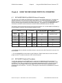
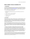
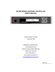
Figure 2.1 (page 6) shows two views of the RC2000 chassis. Looking down on the controller from above
shows the transformer mounted in the left third of the housing, the drive board in the center, and the
digital board on the right. AC Power enter the housing through the back panel on the left. The LCD
display and keypad are mounted on the front near the drive and digital boards respectively.
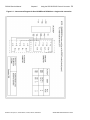
Figure 2.2 (page 7) shows the interconnects between the major subassemblies of the RC2000. The
primaries of the transformer are connected to the power entry module through the front-panel switch /
circuit breaker. A secondary drive breaker is located in the back panel. AC power from the transformer
secondaries enters the drive and digital boards through Molex connectors. Ribbon cables provide the
interconnect between the digital board and the drive board, the keypad, and the display.
2.2
Digital Board
The digital board, shown in Figure 3 is 7 3/4 inches long, 5 3/4 inches wide, and 2 inches tall with the
installed components. The board contains two 16-pin header connectors J2 for the LCD display and J7
for the drive board. A single 14-pin header provides connection to the rotating feed drive option. The
back side of the board holds the 11-terminal interface connector, J1 and DB-9 female connector J5 that
in the communications interface.
The digital board for the RC2000 antenna controller, shown schematically in Figure 4, contains the 8097BH
micro-controller and its support peripherals, the interface to the 4 by 4 matrix keypad, the interface to the 2
row by 40 column LCD (liquid crystal display) module, the Programmable Logic Devices (PLD) which control
the solid state azimuth and elevation motor drives, the azimuth and elevation position sense pulse counters,
the analog voltage signal strength inputs (also referred to as the AGC inputs - Automatic Gain Control
inputs), the transceivers for the serial RS-422 serial port, the polarotor drive circuits, and the 5 volt power
supply.
2.2.1
8097BH Micro-Controller and Support Peripherals
The RC2000 is based on the Intel 8097BH micro-controller running at 10 MHz in the 8-bit bus mode. The
8097BH is a 16 bit micro-controller with 230 onboard 8 bit registers, an asynchronous serial port, an 8
channel 10 bit Analog to Digital converter, built-in timers, and a high speed I/O system.
The micro-controller and its support peripherals consists of the following components:
The 8097BH micro-controller (U1) is running at 10 MHz in the 8-bit interface mode.
An Intel 5C032 Programmable Logic Device (PLD) (U2) decodes the latched address and provides chip
select signals to the EPROM, static RAM (random access memory), real time clock (RTC), and parallel
port. The static RAM chip select line is active high; all other chip selects are active low.
The 74LS373 latch (U3) latches the lower 8 address bits. The upper address bits are latched by the microcontroller. The controller software is stored in the 27C512 EPROM (electrically programmable read only
memory) (U4). The 27C512 is configured as 8 bits by 64 Kilobytes.
Research Concepts, Inc; 10679 Widmer; Lenexa, Kansas; USA 66215
WWW.RESEARCHCONCEPTS.COM
RC2000 Service Manual
Chapter 2
Theory of Operation
6
Figure 2.1 RC2000 Top and Front Views
Research Concepts, Inc; 10679 Widmer; Lenexa, Kansas; USA 66215
WWW.RESEARCHCONCEPTS.COM
RC2000 Service Manual
Chapter 2
Theory of Operation
7
Figure 2.2 RC2000 Interconnection Diagram
Research Concepts, Inc; 10679 Widmer; Lenexa, Kansas; USA 66215
WWW.RESEARCHCONCEPTS.COM
RC2000 Service Manual
Chapter 2
Theory of Operation
8
The 6264LP is an 8K x 8 low power static RAM (U5) with battery backup provided by circuitry on the digital
board. The static RAM uses 2 chip selects. CE2 is an active high chip select which is produced by U2. /CE1
is an active low chip select produced by U7. /CE1 insures that if a powerdown occurs during a write cycle the
contents of the static RAM will not be corrupted.
The MSM62X42BRS real time clock (RTC) (U6) integrated circuit (IC) maintains the system time and date.
The RTC includes a built-in crystal. The RTC has 2 chip selects. The /CS0 chip select is generated by the
address decode PLD. The CS1 chip select is tied to the micro-controller reset line (/RST). If the system
powers down during a write to the RTC the CS1 chip select prevents corrupt data from being written to the
RTC.
IC U7 is the Maxim MAX691 microprocessor supervisory circuit. This circuit provides a number of important
functions...
When the system is powered down this circuit provides battery power to the static RAM and the RTC.
On powerup, this IC holds the active low microprocessor reset line (/RST) low until the system power has
stabilized. The active high reset RST is used to initialize the 82C55. The /CE OUT output is used to control
one of the chip selects for the static RAM. This prevents corrupt data from being written to the RAM during
a powerdown. The /RST line performs a similar function with the RTC
The PFI input and the voltage divider formed by R5 and R6 is used to monitor the battery voltage. If the
battery voltage falls below 2.275 volts the /PFO output signals the micro-controller that the battery voltage is
low.
The 82C55 (U8) provides three 8 bit parallel I/O ports. Port A is configured for input, and ports B and C are
configured for output.
2.2.2
Keypad
The controller uses a 4 by 4 matrix keypad. The keyswitches are closed when the user depresses a key.
The micro-controller detects keystrokes by causing each row of the keypad to sequentially strobe low and
then monitoring the keypad column inputs. The keypad column inputs are pulled high with resistor network
RN4. The 74LS156 2 to 4 line decoder (U12) is used to strobe the keypad rows low. The decoder has open
collector outputs so that if two keys are depressed simultaneously there is no contention between decoder
outputs. When a key is depressed, that key's column input to the 82C55 will be low when the key's row is
strobed low by the decoder.
2.2.3
LCD Display
The LCD is connected to port 1 of the micro-controller. The LCD is used in 4-bit interface mode.
Potentiometer P1 adjusts the contrast of the LCD display.
2.2.4
Motor Control Circuitry
The azimuth and elevation axis motors are powered by a pair of MOSFET based H bridge control circuits.
The upper MOSFETs of each bridge are P channel type and the lower MOSFETs are N channel type. The
individual MOSFETs of the H bridges are controlled by a pair of state machines implemented via Intel
5C060 PLDs (U9 azimuth, U10 elevation). The state machine clocks are derived from the 3.33 MHz microcontroller CLKOUT (clockout) output.
2.2.5 Description of the signals which control the state machine and which are generated by
the state machine
Research Concepts, Inc; 10679 Widmer; Lenexa, Kansas; USA 66215
WWW.RESEARCHCONCEPTS.COM
RC2000 Service Manual
Chapter 2
Theory of Operation
9
Figure 2.3 Digital Board Layout
Research Concepts, Inc; 10679 Widmer; Lenexa, Kansas; USA 66215
WWW.RESEARCHCONCEPTS.COM
RC2000 Service Manual
Chapter 2
Theory of Operation 10
Figure 2.4 Digital Board Schematic
Research Concepts, Inc; 10679 Widmer; Lenexa, Kansas; USA 66215
WWW.RESEARCHCONCEPTS.COM
RC2000 Service Manual
Theory of Operation 11
Chapter 2
MODESEL2, MODESEL1, MODESEL0 ... these signals are generated by the micro-controller. These
signals are the commands for the state machine. Here are the various commands which may be present
on these lines ...
BRAKE (000) ... the two lower MOSFETs of the bridge are on. This mode is used to stop the motors by
means of dynamic braking.
IDLE (001) ... all MOSFETs off. This state is active when an alarm is detected.
SLOW MOVEMENT EAST or DOWN (010) ... In this mode the motors are pulsed on and off to achieve
slow speed movement. The source of the pulse is the TACHIN input to the PLD. The TACHIN input is
generated by the micro-controller.
SLOW MOVEMENT WEST or UP (011) ... In this mode the motors are pulsed off and on to obtain slow
speed movement in either the west or up direction.
FAST MOVEMENT EAST or DOWN (100) ... In this mode the motors are turned on to achieve fast
movement in either the east or down direction.
FAST MOVEMENT WEST or UP (101) ... In this mode the motors are turned on to achieve fast movement
in either the west or up direction.
RESET ... This mode commands the state machines to reset the alarm state.
ALARM ... This mode commands the state machine to enter the alarm state.
TACHIN ... This input is generated by the micro-controller. It is used to pulse the motors off and on during
slow speed movement. The RC2000 implements a digital servo system. When the user specifies a slow
speed code, he or she is indirectly specifying the desired rate at which position pulses will occur when the
antenna is moving slow. The micro-controller varies the pulse width modulated waveform on the TACHIN
pin to vary the speed of the motor so that position pulses arrive at the rate specified by the slow speed code.
ALMLATCH (alarm latch - pin 21) ... This output from the state machine drives the alarm relay on the
analog board. The alarm relay is opened whenever an over-current condition is detected by the state
machine or the state machine is commanded to enter the alarm state by the micro-controller.
ASTAT1, ASTAT0 ... These outputs (from the state machine) are used to inform the micro-controller of the
alarm status of the state machine. 00 means no alarm, any other combination means that the state machine
is in the alarm state.
The state machine clock is derived from the micro-controller CLKOUT output. Whenever the microcontroller changes the mode bits the clock to the state machine is disabled. The clock to the state machine
is present on pins 1 and 13 of the PLD. The CLKOUT pin of the micro-controller is connected to the CLKIN
pin of the PLD. The microcontroller controls the clock via the CLKEN (clock enable) input to the PLD. The
PLD logically ANDs the CLKEN and CLKIN signals to produce the CLKOUT (clockout - pin 22) signal. The
clockout signal goes to the 74HC4060 pre-scaler. The input clock frequency is divided down and presented
to the CLK1 and CLK2 inputs of the PLD.
2.2.6
Pulse Position Sensors
The pulses from the azimuth and elevation position sensors are processed by a comparator circuit (U15 azimuth, U16 - elevation). Resistors R13 and R15 form a voltage divider which presents 2.5 volts to the
non-inverting input of the LM311 comparator. R17 and R14 are used to create hysteresis in the
comparator circuit and eliminate jitter in the output of the comparators.
Research Concepts, Inc; 10679 Widmer; Lenexa, Kansas; USA 66215
WWW.RESEARCHCONCEPTS.COM
RC2000 Service Manual
2.2.7
Theory of Operation 12
Chapter 2
Signal Strength Input Circuits
The RC2000 accepts 2 analog voltages proportional to received signal strength. The controller will use the
strongest signal. The signal strength inputs are normally connected to the AGC (automatic gain control)
output of a satellite receiver. Each channel has an offset and gain adjustment. The purpose of these
adjustments is to expand the range of the AGC signal output by the receiver for measurement by the microcontroller.
The micro-controller has an 8 channel 10 bit A/D converter which converts voltages in the range of 0 to 5
volts. The range of inputs accepted by the signal strength input circuits is 0 to 10 volts. The first op amp in
each circuit is operated in a voltage follower mode. R40 and R45 form a voltage divider. If a greater input
voltage range is required a series resistor can be placed on the input. Potentiometer P4 adjusts the gain
and potentiometer P3 sets the offset. Components R45, R35, C40, and C41 provide a single stage input
filter with a time constant of 39 msec.
2.2.8
RS-422 Serial Port
U13 and U14 are RS-422 transceivers. RS-422 uses a differential signals of 0 or 5 volts. The transmit pins
of the RS-422 port are tri-stated when the RC2000 is not transmitting. These features allow many RS-422
devices to be daisy chained together. The transmit enable function is implemented using PC.2 of the 82C55.
The data format is 7 data bits with even parity and 1 stop bit at user selectable data rates up to 9600 baud.
2.2.9
Polarotor Drive Circuit
The polarotor drive is implemented using FET Q1. The polarotor has its own separate 5.7-volt supply
implemented using VR2. VR2 is a 5-volt regulator. R30 and R31 form a voltage divider which maintains
the GND terminal of the voltage regulator at 0.7 volts.
2.2.10 5 Volt Power Supply
VR1 is a 5-volt switching power supply which provides power to the digital board. The input to the voltage
regulator is a center tapped 18-volt transformer secondary.
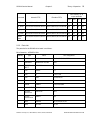
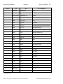
2.2.11 Parts List
The following pages contain the parts list for the RC2000 digital board.
Bill of Materials…RC2KDIG2.S01
Quantity
Type
Value
Ref. Designators
1
27C512
U4
1
5C032
U2
2
5c060
U10,U9
2
75ALS176
1
8097BHN
U1
1
82C55
U8
1
BAT
75ALS176
DL2450
U13,U14
B1
Research Concepts, Inc; 10679 Widmer; Lenexa, Kansas; USA 66215
WWW.RESEARCHCONCEPTS.COM
RC2000 Service Manual
Quantity
Theory of Operation 13
Chapter 2
Type
Value
Ref. Designators
7
CAP
4.7T
C1,C14,C26,C28,C3,C4,C5
21
CAP
.1
C10,C11,C12,C13,C15,C16,C17,C18,C19,C2,C20,
C25,C27,C31,C32,C34,C35,C43,C6,C7,C8
4
CAP
100p
C21,C22,C23,C24
1
CAP
470uF
C30
1
CAP
10
C33
2
CAP
30p
C38,C39
2
CAP
.039
C40,C41
2
CAP
4.7
C42,C9
1
CDM6264
6264LP
U5
1
CRYSTAL
10M
X1
1
DB9F
1
DIODE
1N4685
D1
3
DIODE
1N5396
D11,D7,D8
2
DIODE
1N4737
D13,D14
4
DIODE
MPTE5
D2,D3,D4,D5
2
IDC2X8
1
IND
4
INTAB2
1
LM2575-5
2
LM311NE
U15,U16
2
LMC662C
U18,U19
1
MAX691
U7
1
MSM62X42BRS
U6
8
OUTTAG
U24,U25,U26,U27,U28,U29,U30,U29
1
POLCAP
2200uF
C29
3
POT
5K
P1,P4,P6
1
POT
10K
P2
J5
J2,J7
470uH
L1
U20,U21,U22,U23
LM2575-5
VR1
Research Concepts, Inc; 10679 Widmer; Lenexa, Kansas; USA 66215
WWW.RESEARCHCONCEPTS.COM
RC2000 Service Manual
Quantity
Theory of Operation 14
Chapter 2
Type
Value
Ref. Designators
2
POT
2K
P3,P5
1
REF02H
REF02H
U17
3
RES
100
R10,R18,R29
2
RES
220
R11,R19
6
RES
470
R12,R20,R26,R28,R39,R44
7
RES
1K
R13,R15,R16,R21,R23,R24,R9
2
RES
5.1K
R14,R22
3
RES
1OOK
R17,R25,R38
5
RES
1M
R27,R35,R40,R45,R46
1
RES
240
R30
1
RES
33
R31
1
RES
6.8
R34
2
RES
20K
R36,R37
1
RES
10M
R4
2
RES
10K
R41,R42
1
RES
430K
R43
1
RES
8.2M
R5
1
RES
7.5K
R6
2
RES
300
R7,R8
1
RES4SIPA
2K
RN1
2
RES4SIPA
4.7K
RN4,RN5
2
RES8SIPI
91
RN2,RN3
1
SCHOTTKEY
1N5821
D10
1
SCHOTTKEY
P6KE27A
D9
1
SN74ALS373N
U3
1
SN74HC4060N
U11
1
SN74LS156N
U12
Research Concepts, Inc; 10679 Widmer; Lenexa, Kansas; USA 66215
WWW.RESEARCHCONCEPTS.COM
RC2000 Service Manual
Quantity
Chapter 2
Type
Value
Theory of Operation 15
Ref. Designators
1
TMOSN
BS170
Q1
1
TRANZORB
P6KE6.8
D12
1
VOLTREG
LM140-5
VR2
1
ZORB
P6KE6.8
D6
Total Parts: 147
2.3
Drive Board
The motor drive board, located in the center of the RC2000 chassis, contains the circuitry which converts
the AC power from the drive winding of the transformer to DC and, using solid-state devices, switches
this DC power across the motor drive lines. Other circuitry on the board monitors the current flow to the
motors and provides fail-safe drive power interruption.
2.3.1
Assembly Diagram
The drive board, shown in Figure 5 is 7 3/4 inches long, 4 inches wide, and 3 inches tall with the installed
components. On the left side of the board is a large aluminum heatsink on which is mounted eight
MOSFET devices. On the front of the board near the 3-terminal power inlet Molex connector, J1, are
two normally open drive relays. The back side of the board holds the 6-terminal drive output connector,
J2. Control of the various board functions is performed by the digital board through the 16-pin header,
J3.
2.3.2
Circuit Description
Figure 6 contains the schematic diagram for the drive board. AC power enters the drive board from the
secondary of the transformer through connector J1 after having been routed through the rear-panelmounted, 12 amp, circuit breaker. The power is converted to an unloaded 40 VDC through bridge
rectifier, BR-1 and capacitor, C2. Two relays, K1 and K2, provide a normally open connection to the
azimuth and elevation drive MOSFETs respectively. These 24 VDC relays are actuated through open
collector Darlington drivers U2A and U1A and voltage dropping resistors R12 and R13. A series-pass
voltage regulator, VR1, provides a 12-volt supply for the current sensing circuitry. The combination of
resistor R38 and diode D11 performs a "pre-regulation" function to limit power dissipation in VR1.
2.3.3
Current Sensing Circuitry
The azimuth drive current flows through a precision power resistor, R17. The voltage drop across the
resistor is scaled by the resistor network, R14-R16 and R18-R20. This voltage is presented to the lowpass difference amplifier circuit consisting of OP-AMP U3B and surrounding circuitry. This provides a
single ended voltage which is proportional to average current flow with the characteristic of about 0.166
volts/amp. This sense voltage is then presented to a comparator circuit consisting of U3A and
surrounding circuit elements. Potentiometer P1 provides the comparison voltage which triggers the drive
fault signal, an active high TTL level on pin 8 of header J3 labeled AZ_FAULT. A precision voltage
reference, U3E, provides a stable 5.5-volt reference signal for P1. The standard factory adjustment for
P1 is for an azimuth test point voltage ( at AZ_TP) of 3.25 volts. An exact duplicate of this circuit
performs the current sensing function for the elevation axis.
Research Concepts, Inc; 10679 Widmer; Lenexa, Kansas; USA 66215
WWW.RESEARCHCONCEPTS.COM
RC2000 Service Manual
Theory of Operation 16
Chapter 2
Figure 2.5 Drive Board Layout
Research Concepts, Inc; 10679 Widmer; Lenexa, Kansas; USA 66215
WWW.RESEARCHCONCEPTS.COM
RC2000 Service Manual
Chapter 2
Theory of Operation 17
Figure 2.6 Drive Board Schematic
Research Concepts, Inc; 10679 Widmer; Lenexa, Kansas; USA 66215
WWW.RESEARCHCONCEPTS.COM
RC2000 Service Manual
2.3.4
Chapter 2
Theory of Operation 18
FET H-bridge
The DC drive signal is connected across the motor lines through the use of a solid-state switch
configuration known as an “H-bridge.” This name arises due to the switch elements being located on the
four vertical sections of an “H” and the motor located in the center section of the “H.”
Referring to the azimuth H-bridge portion of Figure 6, drive voltage is applied to the two output lines, AZ
Drive 1 and AZ Drive 2, of connector J2 buy turning on alternate pairs of FET devices. To apply forward
bias across the output lines, FETs Q2 and Q3 are biased on and FETs Q1 and Q4 are biased off. To
apply reverse bias, Q2 and Q3 are biased off while Q1 and Q4 are biased on. By allowing Q1 to remain
on, Q2 and Q3 to remain off, and rapidly switching Q4 off and on with a prescribed duty cycle, motor
speed can be controlled. By turning off Q1 and Q2, and turning on Q3 and Q4, a low resistance current
path is established between the two motor drive lines. This H-bridge mode acts as a dynamic motor
break. Metal oxide varistors across the two drive lines and in shunt from each of them to ground provide
a degree of protection from lighting strike induced voltage transients. A duplicate of the H-bridge,
consisting of Q5 - Q8, performs the switching functions for the elevation axis.
2.3.5
Biasing of the MOSFETs
The MOSFETs used for power switching on the drive board are of two types: P-channel and N-channel.
The P-channel devices, Q1, Q2 and Q5, Q6, make the connection between the positive supply and the
motor drive lines. N-channel devices, Q3, Q4 and Q7, Q8 are used for making connections between the
controllers power supply common node and the motor drive lines. Both the P-channel and N-channel
FET are turned on (biased to a low resistance condition) by application of the correct gate-to-source bias
voltage.
The bias circuitry for the P-channel FET, Q1, will be explained in detail. The other P-channel FETs, Q2,
Q5, and Q6, operate in a similar manner. In the off condition, a logic “0” is applied to the input of the
open-collector Darlington driver U2:C. The driver remains in the off condition, allowing the output (pin
14) to float to the drive supply input level. Since no current is flowing through the resistor pair R1 and
R2, the voltage presented to the FET gate is very nearly the same as the voltage on the source. This
gate-to-source voltage of near zero holds the FET in the “off” condition.
A logic “1” applied to the driver U2:C forces the driver output to the “on” condition with typical levels of
0.9 volts to 1.6 volts. This condition allows current to flow through resistor-pair R1-R2 with their junction
being held to 12 volts below the voltage on the FET source (typically 28 volts) by zener diode D1. This
voltage is presented to the FET gate which allows the FET to enter the “on” state.
The bias circuitry for the N-channel FET, Q3, will be explained in detail. The other N-channel FETs, Q4,
Q7, and Q8, operate in a similar manner. A logic “0” is applied to the input of the open-collector
Darlington driver U2:B. The driver remains in the off condition, allowing the output (pin 5) to float to the
12 volts prescribed by the network of R3 and zener diode D2. This voltage is presented to the gate of
Q3 through resistor R5 and forces the FET into the low resistance “on” state.
A logic “1” applied to the driver U2:B forces the driver output to the “on” condition with typical levels of
0.9 volts to 1.6 volts. This condition forces the junction of R3 and D2 to this level. This voltage is
presented to the FET gate which holds the FET in the “off” state.
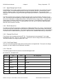
The FET bias conditions and drive output polarity for various move commands may be found in the table
on the following page.
Research Concepts, Inc; 10679 Widmer; Lenexa, Kansas; USA 66215
WWW.RESEARCHCONCEPTS.COM
RC2000 Service Manual
Theory of Operation 19
Chapter 2
Drive Polarity on J2
output terminals
Command
Azimuth FETs
Elevation FETs
AZ1
AZ2
EL1
EL2
AZ_East
Q1=off,Q2=on,Q3=on,Q4=off
Q5=na,Q6=na,Q7=na,Q8=na
+V
0V
0V
0V
AZ_West
Q1=on,Q2=off,Q3=off,Q4=on
Q5=na,Q6=na,Q7=na,G8=na
0V
V+
0V
0V
EL_Up
Q1=na,Q2=na,Q3=na,Q4=na
Q5=on,Q6=off,Q7=off,Q8=on
0V
0V
0V
V+
EL_Down
Q1=na,Q2=na,Q3=na,Q4=na
Q5=off,Q6=on,Q7=on,Q8=off
0V
0V
V+
0V
“Brake”
Mode
Q1=off,Q2=off,Q3=on,Q4=on
Q5=off,Q6=off,Q7=on,Q8=on
0V
0V
0V
0V
2.3.6
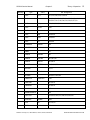
Parts List
The parts list for the RC2000 drive board is as follows:.
Bill of Materials…AZELDRV2.S01
Quantity
Type
Value
Ref. Designators
8
IN4742
IN4742A
D1,D10,D2,D3,D4,D7,D8
1
BREAKER
W28-XQ1A-12,P&B
CB1
1
BRIDGE
RECT
MB354W
BR1
1
CAP
.039uF
C1
3
CAP
.1
C10,C7,C8
4
CAP
.039
C3,C4,C5,C6
1
CAP
10
C9
4
DIODE
IN4002
D12,D13,D5,D6
1
CONNECTOR
IDC2X8
J3
1
VOLTAGE
REGULATOR
LM317TB
VR1
1
OP-AMP/
COMPARATOR
LM613
U3
6
MOV
V68Z10
V1,V2,V3,V4,V5,V6
2
MOV
68-14m
V7,V8
Research Concepts, Inc; 10679 Widmer; Lenexa, Kansas; USA 66215
WWW.RESEARCHCONCEPTS.COM
RC2000 Service Manual
Quantity
Theory of Operation 20
Chapter 2
Type
Value
Ref. Designators
1
POLCAP
3300uF/63V
C2
2
POT
50K
P1,P2
2
RELAY-SPST
T90S1D12-24
K1,K2
8
RES
3.6K
R1,R10,R2,R28,R29,R36,R37,R9
1
RES
3.6K,.5W
R11
2
RES
390,1W
R12,R13
8
RES
1.1K,1%
R14,R15,R18,R19,R21,R22,R25,R26
4
RES
475,1%
R16,R20,R23,R27
2
RES
.05
R17,R24
5
RES
7.5K
R3,R30,R35,R57,R8
8
RES
27K
R31,R32,R33,R34,R4,R5,R6,R7
1
RES
560/1W
R38
1
RES
240
R39
1
RES
2K
R40
4
RES
8.25K
R41,R42,R45,R46
4
RES
162K
R43,R44,R47,R48
2
RES
200K
R49,R50
2
RES
10M
R51,R54
2
RES
5.1K
R52,R55
2
RES
3.3K
R53,R56
1
RES
2.2K
R58
1
RES
1.0K
R59
4
TMOSN
MTP25N10E
Q3,Q4,Q7,Q8
4
TMOSP
MTH20P10
Q1,Q2,Q5,Q6
2
UNL2003A
1
ZORB
U1,U2
1N454A
D11
Total Parts: 109
Research Concepts, Inc; 10679 Widmer; Lenexa, Kansas; USA 66215
WWW.RESEARCHCONCEPTS.COM
RC2000 Service Manual
Chapter 3
Chapter 3
Acceptance Test Procedure
21
ACCEPTANCE TEST PROCEDURE
This test procedure is followed by test personnel at the factory.
1. Turn on test bench power supplies and voltmeters. Install EPROM, EPLD, and clock devices as
specified for the particular model being tested. Verify the orientations of all installed ICs.
2. Place the input voltage switch of the 2000 into the 115V position. Plug in the unit.
3. Turn on the RC2000 using the front panel circuit-breaker/power switch. Adjust the “LCD Contrast”
pot, located on the digital board near the ribbon connector J2, to obtain a readable front panel
display.
4. Install the coincell battery [Duracell DL2450] in the battery holder on the digital board.
5. Attach the ground leads from the voltmeter and power supply to the RC2000 chassis.
6. Adjust pot P2, labeled “VREF TRIM” located in the front, left corner of the digital board while
measuring the voltage at the test point labeled “VREF”. Set the voltage at 5.000 VDC.
7. On the drive board, set both the AZ_TP and EL_TP test points for voltage readings of 3.25V using
trim pots P1 AZ_CL and P2 EL_CL, respectively.
8. Set SS1 offset voltage at wiper of OFF1 pot P3 (digital board--junction with 10K Resistor R41) to
0.50 VDC using the OFF1 pot P3.
9. Set SS2 offset voltage at wiper of OFF2 pot P5 (digital board--junction with 20K Resistor R37) to
0.75 VDC using the OFF2 pot P5.
10. Adjust the power supply to 0.30V and hookup to the SS1 input (digital board--pin 1 on connector
J1). Adjust the gain pot G1 (pot P4) to obtain 3.75V at the SS_1 test point. If testing the “B” or “C”
version, go to the limits mode and note the SS1 reading. (should be about 800)
11. Adjust the power supply to 2.5V and hookup to the SS2 input (digital board--pin 2 on connector J1).
Adjust the gain pot G2 (pot P4) to obtain 3.75V at the SS_2 test point. If testing the “B” or “C”
version, go to the limits mode and note the SS2 reading. (should be about 800)
12. Verify the +12V supply (+12V +1V) on the digital board by measuring the +12V test point located in
the front-left corner of the board
Verify the +5.7V supply (+5.8V +0.5V) on the digital board by measuring the +5.7V test point
located in the back-left corner of the board.
Verify the CL circuit supply (+11.8V +0.5V) on the drive board by measuring the metal case of VR1
located in the front-right quadrant of the board near the large electrolytic capacitor.
Verify the +5V supply (+5V +0.1V) on the digital board by measuring the +5V test point located in
the front-left corner of the board.
13. Turn off the RC2000 and attach the cables to the test mount at connectors J1 and J2.
14. Turn the unit on. It should come up in limits mode. Toggle the mode key to bring up CONFIG
mode. Scroll up to RESET SYSTEM DATA” and then enter the 41758 code. IF RESET SYSTEM
DATA does not appear during the scrolling, then expert access mode must be turned on with the
41758 code. After a successful system data rest the unit should return to limits mode.
15. In limits mode press any key to continue. Set the east limit by pressing the “E” key and verifying
that the AZ count value is decreasing. Then press 7 to set the east limit. The AZ count should now
Research Concepts, Inc; 10679 Widmer; Lenexa, Kansas; USA 66215
WWW.RESEARCHCONCEPTS.COM
RC2000 Service Manual
Chapter 3
Acceptance Test Procedure
22
read thirty. Set the west limit by pressing the “W” key and verifying that the AZ count value is
increasing. Then press 7 to set the west limit. Hit the BKSPC key to confirm the limits setting.
16. Set the down limit by pressing the “S” key and verifying that the EL count value is decreasing.
Then press 9 to set the down limit. The EL count should now read 30. Set the up limit by pressing
the “N” key and verifying that the EL count value is increasing. Then press 9 to set the UP limit. Hit
the BKSPC key to confirm the limits setting.
17. If the controller is the “B” or “C” version go to CONFIG mode and scroll to “ENTER DATE” to set
the date and time.
18. Return to config mode and scroll to REMOTE MODE ENABLE. Set it to 1. (this is not available on
the RC2000B) Scroll to AUTOPOL ENABLE and set it to 1.
19. Toggle the mode key to reach SETUP mode. Test the speed control algorithm by pressing the
“Speed” key for a “SLOW” speed display and pressing the “E” key for mount movement. The
speed servo should display status beginning with around 12 on the display ramping up to about 24.
This should accompany a motor speed increase. Repeat this for “S” motion.
20. Select any Satellite from the scrolling list other than the “USER” entry. For “B” and “C” versions
select “NO” for inclined orbit operation. Enter 0.0 for the satellite longitude. Hit enter for east
longitude and select 2, “USER ENTRY” for the polarization data.
21. Press CW and note the movement of the test polarotor. Press H to set. Press CCW and note the
opposite movement of the test polarotor. Press V to set. The RC2000 should now display “DATA
ACCEPTED”.
22. Cycle the power on the RC2000 off, then on. The software should come up in manual mode.
23. Test the autopol function by shorting the probe attached to the H/V input (pin 8 connector J1) to
ground. This action should skew the test polarotor between the two previously stored polarization
positions.
24. The following remote mode test is only valid for “A” and “C” versions. Attach the test
communications cable to the comm. port, J3. Run the program RC2K.EXE on the test computer.
Select the baud rate D, 9600. Select the comm. port in use. Enter “C” and type in the device
address of “50”. Type the letter “E” on the computer keyboard. The PC screen should contain data
in both the top (transmit half) and bottom (receive half) of the screen. “REMOTE” should appear in
the upper right hand corner of the RC2000 display.
25. The following feed drive test is valid only for “A” and “C” versions that contain the optional rotating
feed drive, option RC2KPOL. Install and connect the optional feeddrive. Adjust pot P1 so that the
voltage on the reference pin (pin 3) of the feeddrive is 5.0V. Turn on the RC2000 and attach the
rotating feed test plug to the feeddrive under test. Turn on the unit; go to CONFIG mode and scroll
to the item, POLAROTOR PRESENT. Set this item to 0. Scroll to Autopol enable and set this
item to 0. Go to manual mode, press “CW” and “CCW” to verify rotation of the test feed.
26. Go to CONFIG mode, scroll to RESET SYSTEM DATA, and type in the code 41758. Test
Completed.
Research Concepts, Inc; 10679 Widmer; Lenexa, Kansas; USA 66215
WWW.RESEARCHCONCEPTS.COM
RC2000 Service Manual
Chapter 4
4.1
Chapter 4
Common RC2000 Questions
23
COMMON RC2000 QUESTIONS
Invalid Data Entry
This error can occur in AUTO mode when the user attempts to position the antenna on a satellite which
has been previously stored in non-volatile memory (satellites are stored in non-volatile memory via
SETUP mode) and either the azimuth, elevation, horizontal polarization or vertical polarization data
fields contain invalid data. In this context, invalid data means that the data lies outside the limits
associated with that axis.
4.1.1
Background
When a user stores a satellite in non-volatile memory of an RC2000A the following data elements are
actually loaded into memory...
The satellite name (10 alphanumeric characters), the satellite azimuth and elevation position (in
position counts - 30 to 65535), the satellite horizontal and vertical polarization positions, and the
satellite longitude.
For an RC2000C the following additional information is also stored in non-volatile memory: a flag that
indicates whether or not the satellite is in an inclined orbit, the inclination of the satellite’s orbital plane
with respect to the earth’s equatorial plane (at the time the satellite was stored in memory), and a code
that indicates the satellite band (C or Ku).
4.1.2
Events Typically Associated with the INVALID DATA ENTRY Error Message
This error is generally caused by one of two events...
1. The user has redefined the azimuth or elevation limits, or
2. The user has changed the type of polarization control device via the Rotating Feed Present
CONFIG mode item.
4.1.3
Azimuth and Elevation Limits
The azimuth and elevation limits are set by the user in LIMITS mode. The INVALID DATA ENTRY
alarm can occur if the user...
1. Initially sets the azimuth and elevation limits, then
2. programs some satellites into non-volatile memory, then
3. changes the azimuth and elevation limits (via LIMITS mode) so that the antenna’s range of azimuth
or elevation movement is reduced relative to initial azimuth and elevation limits defined in step 1,
4. If the user attempts to recall (via AUTO mode) a satellite programmed into memory in step 2 and
the azimuth or elevation position associated with that satellite entry is outside the CURRENT
azimuth or elevation limits the controller will not perform the automatic move and the INVALID
DATA ENTRY message will be displayed.
4.1.4
Changing the Polarization Control Device Associated with the Controller
The RC2000 supports two types of polarization control devices...
Research Concepts, Inc; 10679 Widmer; Lenexa, Kansas; USA 66215
WWW.RESEARCHCONCEPTS.COM
RC2000 Service Manual
Chapter 4
Common RC2000 Questions
24
1. A servo type polarization control device based on the Chaparral polarotor. The polarotor has a
three wire interface (5 volts DC, Pulse, and Return). The controller positions the polarotor by
sending a pulse width modulated (pwm) waveform to the polarotor. The off time of the waveform is
fixed at 15 to 20 milliseconds (msec) and the on time varies between 0.8 msec and 2.2 msec. As
the on time of the waveform changes the feed’s polarization angle varies over a range of
approximately 200 degrees. The servo type interface is completely open loop meaning that the
controller has no indication of what the polarotor’s actual polarization position is or if a polarotor is
even connected to the device.
2. The RC2000 can optionally control a rotating feed powered by a 24 volt DC motor (500 ma max)
that uses a potentiometer for position feed back such as the Seavey Engineering model ESA 124D
four port rotating feed. To support this option the RC2KPOL daughterboard must be installed in the
RC2000.
The user selects the polarization control device via the Rotating Feed Present CONFIG mode item. If
the item is set to 0 (NO) the controller assumes that it is interfaced to a polarotor type device. If the
item is set to 1 (YES) the controller assumes that it is attached to a rotating feed type polarization
control device.
If the controller is configured for use with a polarotor type device the controller’s internal representation
of any valid polarization position is a number between 293 (for a clockwise - CW - limit) and 956
(counter clockwise - CCW - limit). The user does not specify the limits for a polarotor type device.
If the controller is configured for use with a rotating feed type polarization control device the user must
specify the limits. The maximum possible range of polarization movement is 0 to 1023. For the
RC2000A the user sets the polarization limits via the POL LIMITS mode. With the RC2000C the user
sets the polarization limits via the CONFIG mode Rotating Feed CW Limit and Rotating Feed CCW
Limit items.
4.1.5
INVALID DATA ENTRY Error Message Due to Polarization Position Data
The INVALID DATA ENTRY message will be displayed anytime the user attempts to position the
antenna on a satellite and the polarization positions stored in the satellite’s non-volatile memory data
entry are outside the current polarization CW and CCW limits for whatever type of polarization control
the RC2000 is currently configured to support. As shipped from the factory, the default rotating feed
CW and CCW limits are 500 and the Rotating Feed Present CONFIG mode item is set to 0 (NO).
One case where this error can occur is if the user has specified a Seavey type rotating feed (via the
CONFIG mode Rotating Feed Present item) and does not have a feed or RC2KPOL daughterboard
connected to the controller. As shipped from the factory, the default rotating feed CW and CCW limits
are 500. If there is no rotating feed connected the controller’s sensed polarization position will be either
0 or 1023 and the controller will store either 0 or 1023 for the horizontal and vertical polarizations.
When the user programs a satellite into the controller’s memory via SETUP mode the controller DOES
NOT check to see that the polarization data is within the current polarization limits - the user will see
the SETUP mode DATA ACCEPTED message. However, when the user attempts to move (via AUTO
mode) to the satellite that has just been entered (via SETUP mode) the controller will display the
INVALID DATA ENTRY message because the current polarization CW and CCW limits are set to 500
(or some other values) but the satellite’s entry in non-volatile memory specifies that the horizontal and
vertical polarization positions are 0 or 1023.
Another case where this can occur is if the controller is configured for one type of polarization control
device, say a polarotor, when a satellite is programmed into non-volatile memory but the user later
changes the polarization control device (in this example to a rotating feed). If a polarotor is originally
specified when the data is stored in non-volatile memory the horizontal and vertical polarization values
stored for the satellite will be between 293 and 956. If the polarization control device is later changed
to a rotating feed device and the user attempts to recall the satellite, the polarization positions stored in
non-volatile memory may be outside the current polarization CW and CCW limits. This will again result
in the INVALID DATA ENTRY message being displayed.
It is not possible to edit an entry in non-volatile memory. The user can only delete (using DELETE
mode) or overwrite (via SETUP mode by specifying the name of a satellite which is already stored in
non-volatile memory) a satellite’s non-volatile memory entry.
Research Concepts, Inc; 10679 Widmer; Lenexa, Kansas; USA 66215
WWW.RESEARCHCONCEPTS.COM
RC2000 Service Manual
4.1.6
Chapter 4
Common RC2000 Questions
25
No Polarization Control Device Attached to the RC2000
If there is no polarization control device used with the RC2000 the controller should be configured for
polarotor operation. This is done by setting the Rotating Feed Present CONFIG mode item to 0 (No).
When storing a satellite in memory (via SETUP mode) make sure that the current polarization position
(displayed to the right of the POL: or PL: banners) is not at the CW or CCW limit. Use the polarization
jog keys (labeled POL CW or POL CCW) to ‘jog’ the polarization out of the limit condition.
4.2
Antenna Azimuth and Elevation Errors
An antenna azimuth or elevation error is indicated on the controller by a flashing ANT AZIM or ANT ELEV
message on the bottom row of the display. The cause of the error is displayed via RESET mode. These
errors are triggered by one of three possible events:
1. The antenna was commanded to move and an overcurrent conditions occurred. In this case the
RESET mode azimuth or elevation error status will display as DRIVE. The RC2000 uses a solid state
drive. The current threshold is 8 amps. There are current limit threshold adjustments on the
controller's drive board (the one with the heat sink).
2. The antenna was commanded to move and no movement was sensed. In this case the RESET mode
elevation error status will display as JAMMED. This could be caused by the antenna actually being
jammed or the sensor could have failed (the antenna was really moving but the movement was not
sensed). If the position sensor failed the controller's position count would be in error.
Note that there is also a thermal circuit breaker present on the controller which protects the drive
circuits. A tripped circuit breaker can trigger the JAMMED alarm. The circuit breaker is accessible via
the back panel. The circuit breaker has tripped and needs to reset if the button on the circuit breaker
is protruding from the mounting bezel. Reset the breaker by depressing the button. It may be
necessary to wait several minutes before the button will stay in.
3. The antenna was not commanded to move and movement was sensed (i.e. a position pulse was
received). When this error occurs the RESET mode elevation error status will display as RUNAWAY.
This error can be caused by:
i) Noise Pickup on the Sensor Lines. Please see the section on Position Count Errors.
ii) The Az/El Fast Deadband or Az/El Slow Deadband CONFIG mode items need to be increased.
When the antenna has been moving and is suddenly commanded to stop, the antenna must coast to a
stop within 'Fast Deadband milliseconds if the antenna was moving fast or within 'Slow Deadband
milliseconds if the antenna was moving slow. If the antenna moves at a single speed the 'Fast and
'Slow Deadband values MUST be set to the same value.
If a position pulse is received by the controller and the controller is not either moving or in a coast
period defined by the Az/El Fast/Slow Deadbands described above a RUNAWAY error will occur.
If the RUNAWAY error occurs immediately after an antenna move it is probably due to insufficient
'Fast or 'Slow Deadband intervals.
For RC2000C model antenna controllers the RUNAWAY error can be disabled. See section 7.3 of the
controller manual. Note that it is generally not advisable to disable RUNAWAY error sensing.
iii) The position sensors are placed on the fundamental axis of the controller. The controller is
designed to be used with antenna's powered by linear actuators which have the position sensors
located on the 'motor' side of the gear reducer. With the position sensors placed on the 'motor' side of
the gear reducer, wind loading will not generate stray position sense pulses.
If the position sensors are located on the fundamental axis of the antenna, movement due to wind will
cause position counts to be produced. The pulse sense circuits of the RC2000 are normally always
Research Concepts, Inc; 10679 Widmer; Lenexa, Kansas; USA 66215
WWW.RESEARCHCONCEPTS.COM
RC2000 Service Manual
Chapter 4
Common RC2000 Questions
26
active - anytime a pulse is received it increments or decrements the position count based on the
direction the antenna was last commanded to move. If a position pulse is received by the controller
and the controller is not either moving or in a coast period defined by the Az/El Fast/Slow Deadbands
described above a RUNAWAY error will occur.
Any time the controller is tracking an inclined orbit satellite and a system error occurs, tracking will halt and
the '**ERROR** SYSTEM" message will be displayed. A system error is any error which generates a
flashing alarm message on the bottom row of the display.
4.3
Antenna Position Sense Errors
The RC2000 antenna controllers are designed to work with pulse type sensors - either reed or Hall Effect.
The controllers can also be used with most electro-optical based pulse sensors. 5.7 volts DC is available
at the back of the controller to power Hall Effect or electro-optical based sensors. Position sense errors
affect the positioning repeatability of the controller. Repeatable antenna positioning is the main
requirement of the antenna controller.
One way to test the positioning accuracy of the controller is to repeatedly move the antenna between 2
satellites stored in the controller's memory. If the controller is experiencing position pulse count errors the
antenna will not return to the peak power position for the satellites. As the antenna is repeatedly moved
between the pair of satellites, the pointing error will increase.
If the antenna controller is used to track inclined orbit satellites, count errors can be easily seen by plotting
the figure eight pattern of the satellite's apparent motion described by the azimuth and elevation values
contained in the controller's program track table. These track table coordinates can be obtained from the
TRAK mode Menu system via the View function. If count errors have occurred the figure 8 pattern will not
close on itself.
4.3.1
1.
Causes of Antenna Position Count Errors
Noise - The cables used to connect the position sensors to the controller must be shielded.
Conductors used to carry motor drive current must not be enclosed within the same shield that is
used for the sense lines. The position sense cable drains should only be connected at the controller.
If the cable is spliced the drain wires must also be connected at the splice. The drains should not be
allowed to come in contact with earth ground at the antenna or at any breaks or splices in the cable.
More information on position sensor cabling is available in Chapter 3 of the RC2000 manual.
If the source of the noise is something other than the drive current of the motor of the axis which is
experiencing the errant count a RUNAWAY error will probably occur. RUNAWAY errors are
described in the section on Antenna Azimuth and Elevation Errors.
2.
The position sensors are placed on the fundamental axis of the controller. For a description of the
errors caused by placement of the position sensors on the fundamental axis of the antenna
controller please see the Antenna RUNAWAY error, item iii, above.
3.
Occasionally, position sensor modules fail. This will generally occur on new actuators. If antenna
count errors persist on a given axis after the cable shield connections have been verified and
RUNAWAY errors are not occurring, the sensor may be dropping pulses. With reed type sensors
this can occur when the reed switch element is not oriented properly in the module. For any type of
sensor loose connections can also cause count errors.
4.4
Track Mode Limit Error
When a track mode limit error occurs tracking will cease and the controller will display the following error
message (as long as TRAK mode is active) '** ERROR ** LIMIT
'. This error message should not to be
confused with the track mode peak limit error message which is '** ERROR ** PEAK LIMIT'.
Research Concepts, Inc; 10679 Widmer; Lenexa, Kansas; USA 66215
WWW.RESEARCHCONCEPTS.COM
RC2000 Service Manual
Chapter 4
Common RC2000 Questions
27
The limit error occurs when the antenna controller is tracking an inclined orbit satellite and one of the
antenna azimuth or elevation limits is reached. For the RC2000B models this can occur either when then
controller is in the Search sub-mode performing a search or when the antenna is being peaked in either
the Step Track or Program Track sub-modes. For the RC2000C the search is truncated at the antenna
limits so this error can only occur when an antenna peakup is in progress.
If this error occurs while peaking the antenna there is really nothing else to do but reset the antenna limits
or reconfigure the actuators to allow greater movement of the antenna. For the RC2000B and RC2000C
POLAR models the procedure for setting up the mount is described in the addendum to the manual
entitled 'Addendum - RC2000C POLAR and RC2000B POLAR Antenna Controller'.
If the error occurs while the Search is in progress the search window may be either too large or not
centered properly. The apparent motion of an inclined orbit satellite is a narrow figure eight shaped
pattern. The height of the figure eight (in degrees - as seen from the surface of the earth) is approximately
2.4 times the inclination of the satellite's orbital plane to the earth's equatorial plane (i.e. for a satellite with
a four degree inclination the height of the figure eight is approximately 10 degrees). The center of the
figure eight will be located on the Clarke belt (where the geostationary satellites are located). The
controller calculates the height of the figure eight based on the satellite inclination specified by the user in
SETUP mode.
If the controller is experiencing Limit errors while searching make sure that the inclination specified via
SETUP mode is not too large. Note that the inclination of an inclined orbit satellite's orbit increases by
approximately 0.9 degree per year.
The width of the controller's search region is controlled by the Azim Search Scale Factor CONFIG mode
item (in the RC2000B) or the Search Width CONFIG mode item (in the RC2000C). The nominal value of
this item is either 3 or 5. If the search window is too wide an adjacent satellite may be 'found' during a
search. Generally the value of this item can be reduced to 1 or 2 without any negative effects.
The center of the figure eight for POLAR trackers is the Geo Position Count specified by the user in
CONFIG mode. For the RC2000B AZ/EL the center of the figure eight is calculated based on the positions
of geostationary satellites in the vicinity of the inclined orbit satellite. ALWAYS VERIFY THE
LONGITUDE VALUES ASSIGNED TO GEOSTATIONARY SATELLITES.
4.5
Gaps in the Program Track Table
A peakup will not occur if there is no signal strength (as defined by the K/L or C Band Threshold CONFIG
mode items). If the transponder on the satellite is down at the sidereal times which correspond to a given
track table entry a peakup will not occur and no data will be entered into the track table.
Another event can cause gaps in the track table. To see this it is necessary to know what triggers peakups
when the STEP track sub-mode is active. When the STEP track sub-mode is active, two events can
cause the controller to initiate a peaking operation.
The first event is if the sidereal time equals a time which corresponds to one of the 48 points in the track
table. These sidereal times are: N * 86164 / 48 where N = 0.47. The current sidereal time can be viewed
via the TRAK Menu described in the manual.
The second event which can trigger a peaking operation is a bit difficult to understand. The controller
remembers the time when the last peaking operation has occurred. The controller also knows the size of
the antenna and the frequency of operation. This allows the controller to calculate the antenna's radiation
(or gain) pattern which is a relationship between signal loss and the angle from antenna boresight. The
controller also knows the inclination of the satellite (this is obtained when the track is initiated via SETUP
mode). By knowing the inclination of the satellite the controller can calculate the angular velocity of the
satellite as seen by the controller when that angular velocity of the satellite is at its greatest (i.e. when the
Research Concepts, Inc; 10679 Widmer; Lenexa, Kansas; USA 66215
WWW.RESEARCHCONCEPTS.COM
RC2000 Service Manual
Chapter 4
Common RC2000 Questions
28
satellite is passing through the earth's equatorial plane). A peakup will be triggered when the time since
the last peakup equals a value that corresponds to a pointing error of Max Track Error dB at the maximum
angular velocity of the satellite as seen by the antenna. The Max Track Error is specified via CONFIG
mode.
If a peakup triggered by the second event is IN PROGRESS when the first event occurs the peakup
position will not be entered into the table. This can occur on the RC2000B AZ/EL and RC2000B POLAR.
This problem can be avoided with the RC2000C model antenna controllers. The RC2000C allows the user
to specify the amount of time that it takes to perform a STEP track peaking operation. The controller will
not allow peakups just before a sidereal time which corresponds to an entry in the track table. See Section
7.3 of the RC2000C manual.
4.6
TRACK Mode PEAK LIMIT Error
The PEAK LIMIT error indicates that the controller had to move the antenna too far during a STEP TRACK
peaking operation. The maximum movement of the antenna from the starting position for a STEP TRACK
operation is limited to prevent the antenna from peaking up on an adjacent satellite. PEAK LIMIT errors
may be caused by the following:
1.
Specifying too large of an antenna diameter or specifying Ku band when tracking a C band satellite.
These cause the controller to calculate too narrow of an antenna beamwidth. The calculated
antenna beamwidth is used to determine the maximum allowable movement from the starting
position for a STEP TRACK operation.
2.
Specifying too small of a satellite inclination. In STEP TRACK mode, the controller performs
peakups often enough so that the maximum antenna pointing error specified by the Max Track Error
CONFIG mode item is not exceeded. If the specified satellite inclination is too small, the peakups
will not occur often enough and the antenna may move far enough during a peakup to trigger the
PEAK LIMIT error.
3.
The C Band AGC Threshold or the K/L Band AGC Threshold is set too low. If the threshold values
are set too low, when the transponder powers down, the AGC signal of the receiver (antenna iooking
at noise) may be above the threshold. In this case the controller would mistakenly assume that the
satellite signal is present and attempt to peak up on the noise.
4.
If the error occurs during a peakup operation while the PROGRAM TRACK submode is active it may
be that the Update Check Interval TRACK mode MENU item is set too large.
5.
Play or looseness in the mount. This is discussed in the section on mechanical hysteresis. If the
step size used for peaking the antenna is approximately the same as the mechanical hysteresis,
when the antenna is commanded to move the actuator will be energized but the pointing angle of
the antenna may not change. This can lead to PEAK LIMIT errors.
4.6.1
Mechanical Hysteresis in the Mount
If the controller moves the antenna to the correct position (count value) during an automatic move but the
antenna must be peaked manually to peak up the signal there may be some play in the mount or the
actuator. Note that if the error increases as more movements occur it is probably a sensor problem - see
the section on Antenna Position Sense Errors for more information.
When there is play in the mount the antenna will peak up in one position when approaching the satellite
from the west and another when approaching the satellite from the east. To test for this move the antenna
quite a distance west of the satellite and manually move the antenna east at slow speed until the peak is
reached. Repeat the procedure when approaching the satellite from the east. The difference in azimuth
position between the 2 peaks is the mechanical hysteresis.
Research Concepts, Inc; 10679 Widmer; Lenexa, Kansas; USA 66215
WWW.RESEARCHCONCEPTS.COM
RC2000 Service Manual
4.7
Chapter 4
Common RC2000 Questions
29
DH Gibralter Mounts
The DH antenna uses a chain drive for the azimuth axis. There is not much resolution on that axis (800
counts per radian for azimuth versus 2600 counts per radian for elevation). The DH antenna is equipped
with a chain tension adjustment on one end of the chain. This adjustment is a threaded rod which tightens
up the chain. To tighten the chain position the antenna so that the azimuth drive sprocket is opposite the
chain tension adjustment and then tighten up the nut on the threaded rod.
There will always be some looseness in the chain. If the controller calculates that the step track azimuth
step size is 1.49 counts the controller will move the antenna 1 count in azimuth - there are no fractional
counts. If the slop in the antenna is 2 counts then moving the antenna 1 count in azimuth "may not
change the actual pointing angle of the antenna". This is the most common cause of PEAK LIMIT
ERRORS. The solution is to increase the MAX TRACK ERROR which will result in larger step sizes.
4.8
AGC Input Notes
It has been found that the AGC (Automatic Gain Control) output of the Drake ESR 1250 Receiver requires
a 50K to 100K pull down resistor to work properly with the RC2000 AGC input circuits. On the back of the
receiver, the resistor can be connected between the TM (tuning meter) and GND (ground) terminals.
Other Drake models may also require this fix.
4.8.1
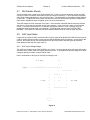
AGC Input Voltage Range
The AGC input voltage range of the RC2000 is 0 to 6 volts. An input voltage above this range will result in
saturation of the output of the AGC signal processing circuit. It is possible to extend the range of the input
voltage by placing a resistor in series with the input.
Here is a schematic of the input of the AGC processing circuit ...
2.4 Meg
|\
| \
input -------/\/\/\/\----+--------|+ \
|
1 Meg
|
+--+-----
|
+---|- /
|
\
|
| /
|
/
|
|/
|
\
|
/
+----------+
....
op amp
|
|
|
__|__
--Figure X
Research Concepts, Inc; 10679 Widmer; Lenexa, Kansas; USA 66215
WWW.RESEARCHCONCEPTS.COM
RC2000 Service Manual
Chapter 4
Common RC2000 Questions
30
The AGC input circuit consists of a voltage divider implemented with a 2.4 and 1 Meg ohm resistors
followed by an op amp voltage follower (see Figure X). The maximum common mode input voltage of the
op amp is approximately 3 volts (worst case). If the input to the voltage divider exceeds 10.2 volts. the
voltage at the input of the op amp will exceed the common mode voltage. To extend the range of AGC
input a resistor can be placed in series with the input. For example, if a 1 Meg resistor is placed in series
with the input, a 13.4 volt input voltage will result in 3 volts at the input of the op amp.
In the event that the AGCsignal from the receiver is very noisy, it is possible to place an additional filter
section in series with the AGC input. The filter section consists of a series resistor and shunt capacitor. A
good starting point for component values is 20K ohm for the resistor and 2.2uF for the capacitor. This
combination will result in a time constant similar to that in the RC2000 and assumes a low AGC port output
impedance. The component values will vary with the output impedance of the receiver AGC port, and
some experimentation may be necessary. If the output impedance is very high, it may be possible to do
away with the series resistor altogether.
Research Concepts, Inc; 10679 Widmer; Lenexa, Kansas; USA 66215
WWW.RESEARCHCONCEPTS.COM
RC2000 Service Manual
Chapter 5
5.1
Chapter 5
Upgrading the RC2000
31
UPGRADING THE RC2000
Updating RC2000 and Nomad Model Antenna Controllers
This paper describes the procedure for upgrading the software (contained in an EPROM memory chip) of
early model RC2000A (Nomad I), RC2000B (Nomad II), and RC2000C antenna controllers. Early versions
of these controllers contain 64k x 8 static RAM (SRAM) chips. Current versions of these controllers
contain 8k x 8 SRAM chips. To run the latest software it is necessary to change the memory map of the
controller. Any model RC2000 antenna controller can be converted to any of the various versions of the
software ('A, 'B or 'C).
To upgrade an early controller to a newer software version, it is necessary to replace the controller's
EPROM memory chip and sometimes the memory select PLD (programmable logic device) chip. When
upgrading from an RC2000A to either a RC2000B or RC2000C it is necessary to install a real time clock
chip. The real time clock chip is an OKI model M62X42B.
Changing the EPROM or PLD has the undesirable side effect of wiping out all data stored in the
controller's non-volatile memory. The procedure outlined in this document allows the user to quickly
restore the controller's non-volatile memory.
5.2
Installing the Upgrade and Restoring Non-Volatile Memory
Here is the procedure for upgrading the software on early model antenna controllers. The use of this
procedure will allow the user to change the controller's memory map and restore the original non-volatile
memory contents. If the software is being upgraded on a unit which is not in service, it is not necessary to
perform this procedure - simply replace the chips and perform a memory reset (from CONFIG mode) to
upgrade the software.
Here is the procedure:
1.
In manual mode, jog the antenna to the west and up limit. Record the position count value for each
axis just before the limit is reached. (If position display in degrees is enabled, disable that feature
before starting this procedure - this feature is available only for certain software versions).
2.
Go to CONFIG mode and record the value of each CONFIG mode item.
3.
Using AUTO mode, position the antenna on each of the geostationary satellites stored in nonvolatile memory. Record the azimuth and elevation positions and the longitude value of each
geostationary satellite. Use the H and V keys to position the polarotor. Record the H and V positions
for each satellite.
4.
Move the antenna to the position just before the east and down limits are reached. This should
correspond to a position count value of 30 for both the azimuth and elevation axis.
5.
Turn the unit off. Replace the EPROM (U4) and PLD (U2) chips. If the controller is being upgraded
to a tracking system from a nontracking system, make sure that a real time clock chip is present in
socket U6. Make sure that the chips are oriented properly in the sockets. The notch on the chip
should line up with the notch of the outline silk-screened onto the printed circuit board under each IC
socket. Make sure that the legs of the chips do not bend up under the IC when they are inserted
into the sockets.
6.
Verify that the chips are oriented properly in the sockets. Power the unit up. Go to CONFIG mode,
bring up the 'RESET SYSTEM DATA' item, and key in 41758 followed by the ENTER KEY to reset
the memory.
Research Concepts, Inc; 10679 Widmer; Lenexa, Kansas; USA 66215
WWW.RESEARCHCONCEPTS.COM
RC2000 Service Manual
Chapter 5
Upgrading the RC2000
32
7.
Go to LIMITS mode. WITHOUT MOVING THE ANTENNA set the down and east limits. AFTER
THE EAST AND DOWN LIMITS HAVE BEEN SET, jog the antenna to the positions for the west and
up limit recorded in step 1. Set the west and up limits. After the west and up limits have been set,
exit LIMITS mode by hitting the MODE KEY.
8.
Go to CONFIG mode and key in the data recorded in step 2 above. Each entry must be terminated
with the ENTER KEY. After the data has been entered scroll through the CONFIG mode items
(using the SCROLL UP and SCROLL DOWN keys) and make sure that the data has been entered
correctly.
9.
In this step, the positions of the geostationary satellites are stored in non-volatile memory. Go to
SETUP mode. Position the antenna on each of the satellites which were recorded in step 3 above.
Select the satellite name, enter the satellite longitude, and move the polarotor to the recorded H and
V positions in response to the appropriate SETUP mode prompts.
Research Concepts, Inc; 10679 Widmer; Lenexa, Kansas; USA 66215
WWW.RESEARCHCONCEPTS.COM
RC2000 Service Manual
Chapter 6
6.1
Chapter 6
Using the RS232-RS422 Protocol Converter 33
USING THE RS232-RS422 PROTOCOL CONVERTER
RC1KADP RS232 to RS422 Protocol Converter
The serial port on RC1000A and RC2000 antenna controllers uses RS422 signal levels. This allows the
antenna controllers to be connected in a daisy chain fashion (i.e. a single PC equipped with a single
RS422 output port can communicate with many antenna controllers). The Standard OMNI830BR satellite
receiver can also accept commands via an RS422 serial port. It is possible for the OMNI830BR to be
connected to an RS422 network which also includes RC1000 and RC2000 antenna controllers.
The following interconnect diagram shows the connections between a PC, the RC1KADP, the RC2000 (or
RC1000) antenna controller, and the Standard Satellite receiver.
IBM PC
RC1KADP
DB 25
DB 9
25 PIN
9 PIN
CONNECTOR CONNECTOR
J1
J2
RC2000 ANTENNA
CONTROLLER
STANDARD RCVR-REMOTE
J3
CONTROL PORT
2
3
RXD
SHLD**
3
2
TXD
RXD
4
6***
7
5
GROUND
/RXD
6
7
TXD
3
4
/TXD
9
8
** If the RS422 cable is shielded, the shield should be connected to the SHLD terminal of connector J2 of
the RC1KADP.
*** For the OMNI830BR to communicate via the RS422 port, RS422 mode must be set via an internal
jumper and the TTL mode must be set to OFF via the front panel.
6.2
RC1KADP Checkout Procedure
To verify the operation of the RC1KADP and PC serial port, a loopback test can be performed. To
configure the RC1KADP for the loopback test, on connector J2 of the RC1KADP, connect RXD to TXD
and /RXD to /TXD. During a loopback text, any character transmitted by the PC is received by the PC.
Use the RC2K_.EXE program found on the diskette included with each antenna controller to send
characters out of the serial port. The RC2K_.EXE program is documented in the README file found on
the diskette.
Research Concepts, Inc; 10679 Widmer; Lenexa, Kansas; USA 66215
WWW.RESEARCHCONCEPTS.COM
RC2000 Service Manual
Chapter 6
Using the RS232-RS422 Protocol Converter 34
Figure 6.1…Interconnect Diagram for Omni 830BR and RC2000 an a single serial connection
Research Concepts, Inc; 10679 Widmer; Lenexa, Kansas; USA 66215
WWW.RESEARCHCONCEPTS.COM
RC2000 Service Manual
Chapter 6
Using the RS232-RS422 Protocol Converter 35
Figure 6.2…Schematic Diagram for the RC1KADP
Research Concepts, Inc; 10679 Widmer; Lenexa, Kansas; USA 66215
WWW.RESEARCHCONCEPTS.COM
RC2000 Service Manual
Chapter 6
Using the RS232-RS422 Protocol Converter 36
6.3
Alternate Test Procedure for the RC1KADP
6.3.1
Test Procedure for RS485A1 Board (RC1KADP)
1.
Clip lead TX1 to RX1 on terminal output strip
2.
Clip lead TX2 to RX2 on terminal output strip.
3.
Connect ground lead to power supply ground and voltmeter ground, then apply to pin
on input terminal strip.
4.
Apply 9V/200mA to J3 jack.
5.
Monitor terminal TXD on J1 with red lead from voltmeter while applying and releasing
6-8VDC to terminal RXD on J1. Applying 6-8VDC to RXC should cause roughly a
9VDC level on TXD; removing the voltage should result in a –9VDC reading.
Research Concepts, Inc; 10679 Widmer; Lenexa, Kansas; USA 66215
WWW.RESEARCHCONCEPTS.COM
TABLE OF CONTENTS
CHAPTER 1
1.1
1.2
1.3
1.4
INTRODUCTION
The RC2000 Antenna Controller Family
Tracking Inclined Orbit Satellites
RC2000B/C Tracking Algorithm
Specifications
CHAPTER 2
THEORY OF OPERATION
2.1
2.2
System
Digital Board
2.2.1
8097BH Micro-Controller and Support Peripherals
2.2.2
Keypad
2.2.3
LCD Display
2.2.4
Motor Control Circuitry
2.2.5
Description of the signals which control the state machine and which are generated by
the state machine
2.2.6
Pulse Position Sensors
2.2.7
Signal Strength Input Circuits
2.2.8
RS-422 Serial Port
2.2.9
Polarotor Drive Circuit
2.2.10 5 Volt Power Supply
2.2.11 Parts List
2.3
Drive Board
2.3.1
Assembly Diagram
2.3.2
Circuit Description
2.3.3
Current Sensing Circuitry
2.3.4
FET H-bridge
2.3.5
Biasing of the MOSFETs
2.3.6
Parts List
CHAPTER 3
CHAPTER 4
4.1
4.2
4.3
4.4
4.5
4.6
4.7
4.8
Invalid Data Entry
4.1.1
Background
4.1.2
Events Typically Associated with the INVALID DATA ENTRY Error Message
4.1.3
Azimuth and Elevation Limits
4.1.4
Changing the Polarization Control Device Associated with the Controller
4.1.5
INVALID DATA ENTRY Error Message Due to Polarization Position Data
4.1.6
No Polarization Control Device Attached to the RC2000
Antenna Azimuth and Elevation Errors
Antenna Position Sense Errors
4.3.1
Causes of Antenna Position Count Errors
Track Mode Limit Error
Gaps in the Program Track Table
TRACK Mode PEAK LIMIT Error
4.6.1
Mechanical Hysteresis in the Mount
DH Gibralter Mounts
AGC Input Notes
4.8.1
AGC Input Voltage Range
CHAPTER 5
5.1
5.2
UPGRADING THE RC2000
Updating RC2000 and Nomad Model Antenna Controllers
Installing the Upgrade and Restoring Non-Volatile Memory
CHAPTER 6
6.1
6.2
6.3
ACCEPTANCE TEST PROCEDURE
COMMON RC2000 QUESTIONS
USING THE RS232-RS422 PROTOCOL CONVERTER
RC1KADP RS232 to RS422 Protocol Converter
RC1KADP Checkout Procedure
Alternate Test Procedure for the RC1KADP
6.3.1
Test Procedure for RS485A1 Board (RC1KADP)
1
1
2
2
3
5
5
5
5
8
8
8
8
11
12
12
12
12
12
15
15
15
15
18
18
19
21
23
23
23
23
23
23
24
25
25
26
26
26
27
28
28
29
29
29
31
31
31
33
33
33
36
36
REVISION HISTORY
1.15.96
* v1.00
First issuance
3.27.96
* v1.10
Added ADP, Large Motor, DH Gibralter, and AGC input information.
11.16.98
* v1.11
Added INVALID DATA ENTRY information; reformat manual
RC2000 Service Manual
v 1.11
RESEARCH CONCEPTS, INC.
LENEXA, KS
(913) 469-4125