1
Operator's
Manual
4-Cycle Garden
MiNi TILLER
Model No. 316.292650
• SAFETY
ASSEMBLY
OPERATION
MAINTENANCE
PARTS LIST
• ESPANOL, R E1
CAUTION: Before using
this product, read this
manual and follow
all
safety rules and operating
instructions.
Sears, Roebuck
and Co., Hoffman
Visit our website:
Estates,
www.sears.com/craftsman
769-04601
P00
IL 60179, U.S.A.
TABLE OF CONTENTS
Service Information .................................
1
Rules for Safe Operation .............................
2
Warranty information ................................
4
Know Your Unit ....................................
5
Assembly instructions ...............................
6
Oil and Gas Information ..............................
7
Starting/Stopping Instructions .........................
8
Operating instructions ...............................
9
Maintenance and Repair Instructions
...................
9
Cleaning and Storage ..............................
13
Troubleshooting Chart ..............................
14
Specifications
....................................
15
Parts List .......................................
E17
Service Information ...............................
E20
SPARK ARRESTOR NOTE
NOTE: For users on U.S. Forest Land and in the states of
California,
Maine, Oregon and Washington.
All U.S. Forest
Land and the state of California (Public Resources Codes 4442
and 4443), Oregon and Washington require, by law that certain
internal combustion engines operated on forest brush and/or
grass-covered
areas be equipped
with a spark arrestor,
maintained
in effective working order, or the engine be
constructed, equipped and maintained for the prevention of fire.
Check with your state or local authorities
for regulations
pertaining to these requirements.
Failure to follow these
requirements could subject you to liability or a fine. This unit is
factory
equipped
with a spark
arrestor.
If it requires
replacement, ask your LOCAL SERVICE DEALER to install the
Accessory Part #753-05297 Muffler Assembly.
CALiFORNiA PROPOSiTiON 65 WARNING
The purpose of safety symbols is to attract your attention to
possible dangers. The safety symbols, and their explanations,
deserve your careful attention and understanding. The safety
warnings do not by themselves eliminate any danger. The
instructions or warnings they give are not substitutes for
proper accident prevention measures.
SYMBOL
MEANING
SAFETY
ALERT: Indicates danger, warning or
caution. Attention is required in order to avoid
,_
erious personal injury. May be used in conjunction
with other symbols or pictographs.
DANGER:
Failure to obey a safety warning will
result in serious injury to yourself or to others.
Always follow the safety precautions to reduce the
risk of fire, electric shock and personal injury.
WARNING:
Failure to obey a safety warning can
result in injury to yourself and others. Always follow
the safety precautions to reduce the risk of fire,
electric shock and personal injury.
CAUTION:
Failure to obey a safety warning may
result in property damage or personal injury to
yourself or to others. Always follow the safety
precautions to reduce the risk of fire, electric shock
and personal injury.
NOTE:
Advises you of information or instructions vital to the
operation or maintenance of the equipment.
Read the Operator's Manual and follow all warnings and
safety instructions. Failure to do so can result in serious
injury to the operator and/or bystanders.
THE ENGINE EXHAUST FROM THIS PRODUCT CONTAINS
CHEMICALS KNOWN TO THE STATE OF CALiFORNiA TO
CAUSE CANCER, BIRTH DEFECTS OR OTHER
REPRODUCTIVE HARM.
FOR QUESTIONS,
CALL
1-800-659-5917
Before beginning, locate the unit's model plate. It lists the model and serial numbers of your unit. Refer to the sample plate below and
copy the information for future reference.
Model Number
Parent Part Number
\MODEL:
ITEM :
/
l
Copy the model and parent part number here:
Copy the serial number here:
= IMPORTANT SAFETY INSTRUCTIONS
READ ALL iNSTRUCTiONS
BEFORE OPERATING
the safety rules. Please read these instructions
before operating the unit in order to ensure the
safety of the operator
WARNING:
When and
usingany
thebystanders.
unit, you must
Please
follow
keep these instructions for later use.
* Read the instructions carefully. Be familiar with the controls
and proper use of the unit.
* Do not operate this unit when tired, i11,or under the influence
of alcohol, drugs, or medication.
* Children and teens under the age of 15 must not use the unit,
except for teens guided by an adult.
=
• All guards and safety attachments must be installed properly
before operating the unit.
Inspect the unit before use. Replace damaged parts. Check
for fuel leaks. Make sure all fasteners are in place and secure.
Replace parts that are cracked, chipped, or damaged in any
way. Do not operate the unit with loose or damaged parts.
Carefully inspect the area before starting the unit. Remove all
debris and hard or sharp objects such as glass, wire, etc.
Be aware of the risk of injury to the head, hands and feet.
Clear the area of children, bystanders, and pets. At a
minimum, keep all children, bystanders, and pets outside a 50
feet (15 m) radius; there still may be a risk to bystanders from
thrown objects. Bystanders should be encouraged to wear
eyeprotection.
Ifyouareapproached,
stoptheunit
immed
iately.
Squeeze
thethrottle
control
andcheckthatitreturns
automatically
totheidleposition.
Makealladjustments
orrepairs
before
usingunit.
SAFETY
WARNINGS
FORGASUNITS
I _hb
vapors can explode if ignited. Take the following
IWARN'NG-"
Gas°line is highly flammable, andits
precautions:
* Store fuel only in containers specifically designed and
approved for the storage of such materials.
* Avoid creating a source of ignition for spilled fuel. Do not start
the engine until fuel vapors dissipate.
* Always stop the engine and allow it to cool before filling the
fuel tank. Never remove the cap of the fuel tank, or add fuel,
when the engine is hot. Never operate the unit without the fuel
cap securely in place. Loosen the fuel tank cap slowly to
relieve any pressure in the tank.
* Add fuel in a clean, well-ventilated outdoor area where there
are no sparks or flames. Slowly remove the fuel cap only after
stopping engine. Do not smoke while fueling or mixing fuel.
Wipe up any spilled fuel from the unit immediately. Always
wipe unit dry before using.
o Move the unit at least 30 feet (9.1 m) from the fueling source
and site before starting the engine. Do not smoke or allow
sparks and open flames near the area while adding fuel or
operating the unit.
WHILE OPERATING
, Never start or run the unit inside a closed room or building.
Breathing exhaust fumes can kill. Operate this unit only in a
well ventilated outdoor area.
Wear safety glasses or goggles that meet ANSI Z87.1-1989
standards and are marked as such. Wear ear/hearing protection
when operating this unit. Wear a face or dust mask if the
operation is dusty.
Wear heavy, long pants, boots, gloves and a long-sleeved shirt.
Do not wear loose clothing, jewelry, short pants, sandals or go
barefoot. Secure hair above shoulder level.
This unit has a clutch. The tines remain stationary when the
engine is idling. If they do not, have the unit adjusted by an
authorized service technician.
Be sure the tines are not in contact with anything before
starting the unit.
Use the unit only in daylight or good artificial light.
Avoid accidental starting. Be in the starting position whenever
pulling the starter rope. The operator and unit must be in a stable
position while starting. See Starting/Stopping Instructions.
I
• Usetherighttool.Onlyusethistoolforthepurpose
intended.
Use extreme caution when reversing or pulling the unit towards you.
Do not overreach. Always keep proper footing and balance.
Take extra care when working on steep slopes or inclines.
Always hold the unit with both hands when operating. Keep a
firm grip on the grips.
Keep hands, face, and feet at a distance from all moving parts.
Do not touch or try to stop the tines when they are rotating.
Do not touch the engine or muffler. These parts get extremely
hot from operation, even after the unit is turned off.
Do not operate the engine faster than the speed needed to
cultivate. Do not run the engine at high speed when you are
not cultivating.
Always stop the engine when cultivating is delayed or when
walking from one cultivating location to another.
If you strike or become entangled with a foreign object, stop
the engine immediately and check for damage. Do not
operate before repairing damage. Do not operate the unit
with loose or damaged parts.
Stop the unit, switch the engine to off, and disconnect the
spark plug for maintenance or repair.
Use only original equipment manufacturer replacement parts
and accessories for this unit. These are available from your
authorized service dealer. Use of any unauthorized parts or
accessories could lead to serious injury to the user, or
damage to the unit, and void your warranty.
Keep unit clean of vegetation and other materials. They may
become lodged between the tines and guard.
To reduce fire hazard, replace faulty muffler and spark
arrestor, keep the engine and muffler free from grass, leaves,
excessive grease or carbon build up.
AFTER USE
Clean tines with a household cleaner to remove any gum
buildup. Oil the tines with machine oil to prevent rust.
OTHER SAFETY WARNINGS
Never store a fueled unit inside a building where fumes may
reach an open flame or spark.
* Allow the engine to cool before storing or transporting. Be sure
to secure the unit while transporting.
* Store the unit in a dry area, locked up or up high to prevent
unauthorized use or damage, out of the reach of children.
* Never douse or squirt the unit with water or any other liquid.
Keep handles dry, clean and free from debris. Clean after each
use, see Cleaning and Storage instructions.
o Keep these instructions. Refer to them often and use them to
instruct other users. If you loan someone this unit, also loan
them these instructions.
SAVE THESE INSTRUCTIONS
• SAFETY AND INTERNATIONAL
SYMBOLS
•
This operator's manual describes safety and international symbols and pictographs that may appear on this product.
manual for complete safety, assembly, operating and maintenance and repair information.
SYMBOL
MEANING
SYMBOL
MEANING
A
AL
• SAFETY ALERT SYMBOL
I Indicates danger, warning or caution. May be used
I in conjunction with other symbols or pictographs.
WARNING:
Read the operator's manual(s)and
follow all warnings and safety instructions. Failure to
so can
result in serious
injury to the operator
o do
READ
OPERATOR'S
MANUAL
and/or bystanders.
I
Read the operator's
oON/START/RUN
ON/OFF STOP CONTROL
,, ON/OFFoFF
or STopSTOP
CONTROL
• HOT SURFACE WARNING
Do not parts
toUchgetahot
surfacelhot
Youmay
get burned.
These
extremely
from operation.
They
remain hot fora short time after the unit is turned off.
• UNLEADED
'_1
• WEAR EYE AND HEARING PROTECTION
WARNING: Thrown objects and loud noise
can cause severe eye injury and hearing loss.
Wear eye protection meeting ANSI Z87.1-1989
standards and ear protection when operating this
unit. Use a full face shield when needed.
FUEL
Always use ciean fresh unleaded fue
I
• OIL
Jl Refertooperatorsmanua forthepr0pertypeofo.
1
A
WARNING:
KeeP all bystanders, eSpecially
• children
KEEP BYSTANDERS
AWAY50 feet (!5 m)from the
and pets, at least
operating area.
•THROWN
OBJECTS AND ROTATING CUTTER
CAN CAUSE SEVERE INJURY
I
WARNING: Do not operate without the cutting
attachment shield in placel Keep away from the I
rotat ng cutt ng attachment.
J
2
H N
I
I
I
I
I
J
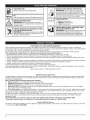
3 I" CHOKE CONTROL
1. : FULLchokeposition
2. PARTIAL choke position
3. = RUN choke post on
I MINI TILLERS - ROTATING TINES
CAN CAUSE SEVERE INJURY
WARNING:
Stop the engine and allow the tines
to stop before installing or removing tines, or
before cleaning or performing any maintenance.
Keep hands and feet away from rotating tines.
I
I
I
I
I
J
CRAFTSMAN TWO YEAR LIMITED WARRANTY
When operated and maintained according to all supplied instructions, if this Craftsman product fails due to a defect in material or
workmanship within two years from the date or purchase, take it to any Sears or other authorized Craftsman location in the United States
for free repair. Call 1-800-4-MY-HOME® for the nearest authorized location.
This warranty applies for only 90 days from the date of purchase if this product is ever used for commercial or rental purposes.
This warranty covers ONLY defects in material and workmanship.
Sears will NOT pay for:
• Expendable items that become worn during normal use, including but not limited to blades, tines, or belts.
• Tire or wheel replacement or repair resulting from normal wear, accident, or improper operation or maintenance.
• Repairs necessary because of operator abuse, including but not limited to damage caused by impacting objects that bend the frame
or motor crankshaft.
• Repairs necessary because of operator negligence, including but not limited to, electrical and mechanical damage caused by improper
storage, or failure to maintain the equipment according to the instructions contained in the operator's manual.
• Repairs necessary due to improper fuel mixture, contaminated or stale fuel.
• Normal deterioration and wear of the exterior finishes, or product label replacement.
This warranty applies only while this product is within the United States. This warranty gives you specific legal rights, and you may also
have other rights which vary from state to state.
Sears, Roebuck and Co., Hoffman Estates, IL 60179
Repair Protection Agreements
Congratulations on making a smart purchase. Your new Craftsman® product is designed and manufactured for years of dependable
operation. But like all products, it may require repair from time to time. That's when having a Repair Protection Agreement can save
you money and aggravation.
Here's what the Repair Protection Agreement* includes:
[]
Expert service by our 10,000 professional repair specialists
[]
Unlimited service and no charge for parts and labor on all covered repairs
[]
Product replacement
up to $1500 if your covered product can't be fixed
[]
Discount of 10% from regular price of service and related installed parts not covered by the agreement; also, 10% off regular
price of preventive maintenance check
[]
Fast help by phone - we call it Rapid Resolution - phone support from a Sears representative. Think of us as a "talking owner's manual."
Once you purchase the Repair Protection Agreement, a simple phone call is all that it takes for you to schedule service. You can call
anytime day or night, or schedule a service appointment online.
The Repair Protection Agreement is a risk-free purchase. If you cancel for any reason during the product warranty period, we will
provide a full refund. Or, a prorated refund any time after the product warranty period expires. Purchase your Repair Protection
Agreement today!
Some limitations and exclusions apply. For prices and additional information
in the U.S.A. call 1=800=827=6655.
*Coverage in Canada varies on some items. For full details call Sears Canada at 1=800=361=6665.
Sears Installation Service
For Sears professional installation of home appliances, garage door openers, water heaters, and other major home items, in the U.S.A.
or Canada call 1=800=4=MY=HOME ®.
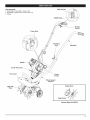
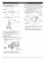
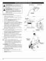
APPLICATIONS
• Cultivating
sodandlighttomedium
soil
• Cultivating
ingarden
areas,
around
trees,
etc.
STOP/OFF
(0}
• Edging
START/ON (I)
Throttle
Control
Primer Bulb
Handlebar
Knob
Handlebar
Muffler
Starter Rope Grip
Tine Guard
Choke
Control
Wheel Support
Bracket
Mini Tiller
Tines
Edger Wheel
Edger Bla__
Optional
Edger Kit 292670
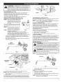
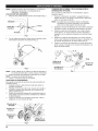
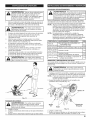
NOTE:Before
setting
upyourminitiller/ edger,
disconnect
the spark plug wire from the spark plug.
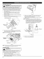
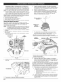
POSiTiONiNG THE HANDLEBARS
1. Loosen the two knobs on the inside of the handlebars (Fig. 1).
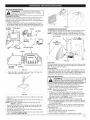
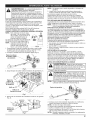
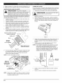
ATTACHING THE OPTIONAL EDGER WHEEL AND BLADE
To convert the mini tiller to an edger, proceed as follows:
1.
Push the On/Off switch to Off (O) position to stop engine and
tines and disconnect spark plug to avoid accidental starting.
NOTE:
Handlebars
2.
Bolt
3.
Handlebar
Knob
It may be necessary to lay the mini tiller / edger back in
a horizontal position on a flat level surface with the
upper handle touching the ground.
Remove the click pin from each end of the tine shaft and
slide the tines off the shaft.
Slide the edger wheel, with the hub facing inward, onto the
right side of the tine shaft and secure with the click pin in
the inside hole (Fig. 4).
Hole
Washer
Edger Guide
Line
Fig. 1
2.
With the unit upright, swing the handlebars up into the
operating position (Fig. 2).
Edg_eer
Wheel
Hub
Click Pin
Tine Shaft
Edger Blade
_
Fig. 4
4.
5.
Fig. 2
NOTE:
Take care not to pinch the throttle cable or switch
wires when positioning the handlebar.
3. Tighten the knobs to secure the handlebars in place.
NOTE: Do not over-tighten the knobs.
4. Reconnect the spark plug wire to the spark plug.
ADJUSTING TINE DEPTH
To adjust the wheel support bracket proceed as follows:
1. Stop engine and disconnect spark plug to avoid accidental
starting.
2. Remove cotter pin from the clevis pin and slide clevis pin
out of tailpiece bracket (Fig. 3).
Clevis Pin
Cotter
Pin
Wheel
Support
Bracket
Tailpiece Bracket
Fig. 3
3.
4.
Slide the wheel support bracket up or down in the
tailpiece, aligning the holes to the desire height.
Place the clevis pin through the hole and secure with cotter
pin.
Slide the edger blade with the hub facing out onto the left
side of tine shaft and secure with the click pin in the inside
hole (Fig. 4).
The edger guide line indicates where cutting will occur.
Guide the unit along a flowerbed, sidewalk, or driveway so
the edger guide line is above the desired line of cut.
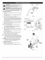
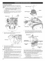
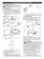
CAUTION:
OVERFiLLiNG OiL CRANKCASE MAY
CAUSE PRODUCT DAMAGE. Check and maintain the
proper oil level in the crank case; it is important and
cannot be overemphasized. Check the oil before each
use and change it as needed. See Changing the Oil.
RECOMMENDED OIL TYPE
Using the proper type and weight of oil in the crankcase is
extremely important. Check the oil before each use and
change the oil regularly. Using incorrect or dirty oil can cause
premature engine wear and failure.
Use a high-quality SAE 30 weight oil of API (American
Petroleum institute) service class SF, SG, SH.
ADDING OiL TO CRANKCASE: INITIAL USE
NOTE: This unit is shipped without oil in
the crankcase, in order to avoid
damage to the unit, put oil in the
crankcase before attempting to
start unit.
Your unit is supplied with one 3.04 fluid
oz. (90 ml) bottle of SAE 30 SF, SG, SH
oil (Fig. 5).
NOTE: Save the bottle to measure the
correct amount for future oil
changes. See Changing the Oil.
NOTE: Your new 4-Cycle mini tiller is
Fig. 5
shipped for operation in
conditions above 40°F (4°C). For cold weather
operation, where temperatures fall below 40°F (4°C),
use a high-quality SAE 10W30 weight oil of API
(American Petroleum Institute) service class SF, SG, SH.
1.
Unscrew the oil bottle top and remove the paper seal
covering the opening. Replace the top and cut the tip off
the funnel spout (Fig. 5).
2.
Place the unit on a flat level surface with the mini tiller in a
horizontal position (Fig. 6).
Plug/Dipstick
Oil Fill
-_
@
Oil Fill
Fig. 8
RECOMMENDED GASOLINE TYPE
Old gas is the primary reason for improper unit performance.
Be sure to use fresh, clean, unleaded gasoline.
NOTE: This is a four cycle engine, in order to avoid damage to
the unit, do not mix oil with gasoline.
Definition of Blended Fuels
Today's fuels are often a blend of gasoline and oxygenates such
as ethanol, methanol or MTBE (ether). Alcohol-blended fuel
absorbs water. As little as 1% water in the fuel can make fuel
form acids when stored. When using alcohol-blended fuel, use
fresh fuel that is less than 60 days old.
Using Blended Fuels
if you choose to use a blended fuel, or if its use is unavoidable,
follow recommended precautions:
* Always use fresh unleaded gasoline
, Use Sta-Bil® or an equivalent
, Drain tank and run the engine dry before storing unit
Using Fuel Additives
The use of fuel additives, such as Sta-Bil® or an equivalent, will
inhibit corrosion and minimize the formation of gum deposits.
Using a fuel additive can keep fuel from forming harmful deposits
in the carburetor for up to six (6) months. Add 0.8 oz. (23 ml.) of
fuel additive per gallon of fuel to an approved gas container
according to the instructions on the container. NEVER add fuel
additives directly to the unit's gas tank.
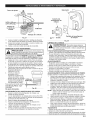
FUELING THE UNIT
outdoor area. Wipe up any spilled gas immediately.
Avoid
creating aAdd
source
fuel. Do
ARNING:
fuel of
in ignition
a clean, for
wellspilt
ventilated
not start the engine until fuel vapors dissipate.
__
_
1.
Fig. 6
3.
Remove the oil plug / dipstick from the crankcase (Fig. 7).
Remove fuel cap. Remove the tag from the fuel tank neck.
_
NOTE:
injury from fuel spray. Never operate the unit without I
|I
WARNING:
Remove
gas cap slowly to avoid
the fuel cap securely
in place.
Fill or add gas to the tank only when the mini tiller is in
a horizontal position (Fig. 9).
Gas Cap
_]]_j
X
£.f
Fig. 9
2.
4. Pour the entire bottle of oil into the oil fill hole (Fig. 8).
NOTE: Never add oil to the gas or gas tank.
5. Wipe up any oil that may have spilled and reinstall the oil fill
plug / dipstick.
The importance of checking and maintaining the proper oil level
in the crankcase cannot be overemphasized. Check oil before
each use and change as specified in the Maintenance Schedule.
Place spout of gas container into the fill hole on the gas
tank and fill tank.
NOTE: Do not overfill tank.
3. Wipe up any gasoline that may have spilled.
4. Reinstall the gas cap.
5. Move the unit at least 30 ft. (9.1 m) from the fueling source
and site before starting the engine.
NOTE: Dispose of the old gasoline in accordance to Federal,
State and Local regulations.
ON (I)
_
ventilated outdoor area. Carbon monoxide exhaust
ARNING:
Operate
unit only
fumes
can be lethal
in a this
confined
area.in a well-
_
you are in the starting position when pulling the starter
rope
(Fig. 12). ToAvoid
avoid accidental
serious injury,
the operator
and
ARNING"
starting.
Make sure
unit must be in a stable position while starting.
OFF (0)
STARTING iNSTRUCTiONS
1.
Check the oil level in the crankcase.
Oil Level.
2.
Fill the fuel tank with fresh, clean unleaded gasoline. Refer
to Fueling the Unit.
Put the On/Off Stop Control in the ON [I] position (Fig. 10).
Place the choke lever in Position 1 (Fig. 11).
Fully press and release the primer bulb 10 times, slowly.
Some amount of fuel should be visible in the primer bulb
and fuel lines (Fig. 11). If you can't see fuel in the bulb,
press and release the bulb as many times as it takes before
you can see fuel in it.
Hold the throttle and handlebar with one hand and grab the
starter rope with your other hand. Use your foot to hold
down the mini tiller (Fig. 12).
3.
4.
5.
6.
NOTE:
7.
8.
Throttle
Control
Refer to Checking the
Tilt the unit back slightly to bring the tines off the
ground when starting.
While squeezing the throttle control, pull the starter rope
with a smooth and steady pull. Repeat this 5 times.
Move the choke lever to Position 2.
Fig. 10
I
Choke Lever
f<
Position 1
Position 2
While squeezing the throttle control, pull the starter rope in
the same manner as explained in Step 7. Pull 1 to 4 times
to start the engine.
10. Keep the throttle squeezed and allow the engine to warm
up for 30 to 60 seconds.
11. Place the choke lever in Position 3. Release the throttle
control to the idle position and begin operation.
Position 3
9.
The engine does not start, repeat Steps 4-11.
The engine fails to start after a few attempts, place the
choke lever in Position 3 and squeeze the throttle control.
Pull the starter rope 3 to 8 times. The engine should start.
If not, continue pulling starter rope until the engine starts.
IF WARM... If the engine is already warm, make sure the
On/Off Stop control is in the ON position and start the
unit with the choke lever in Position 2. After the unit
starts, move the choke lever to Position 3.
Primer Bulb
Fig. 11
IF...
IF...
Starter
Rope
STOPPING INSTRUCTIONS
1.
2.
Release your hand from the throttle control. Allow the
engine to cool down by idling.
Put the On/Off Stop Control in the OFF (O) position (Fig. 10).
Control
Fig. 12
OPERATING
TiPS
__J
1.
MAINTENANCE
2.
3.
4.
perform maintenance or repairs with unit running.
injury when operating this unit. Do not wear loose
clothing or jewelry. Wear eye and ear/hearing
protection.
heavyproperly
long pants,
boots the
andrisk
gloves.
ARNING:WearDress
to reduce
of
Do not wear short pants, sandals or operate barefoot.
__
Move the mini tiller to the work area prior to starting the
engine. Transport the mini tiller by pushing or pulling it
along on its wheels.
never pick-up or carry the unit while the engine is
_WARN[NG:running.
To prevent serious personal injury,
SCHEDULE
j
service and
repair aserious
cool unit.
Disconnect
the
I Always
WARNING:
To prevent
injury,
never
spark plug wire to ensure that the unit cannot start.
Perform these required maintenance procedures at the
frequency stated in the table. These procedures should also be
a part of any seasonal tune-up.
NOTE: Some maintenance procedures may require special
tools or skills, if you are unsure about these procedures,
take your unit to a qualified service dealer.
NOTE: Maintenance, replacement, or repair of the emission
control devices and system may be performed by a
qualified service dealer.
FREQUENCY
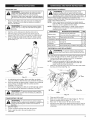
Start the unit by following the Starting Instructions.
With the engine running and the tines off the ground,
depress the throttle control to increase the engine speed.
While holding the upper handle with both hands, slowly
lower the mini tiller until the tines make contact with the
ground (Fig. 13).
MAINTENANCE
REQUIRED
SEE
Before using
Fill fuel tank with fresh fuel
Check oil while the engine is cold
p7
p 10
Every 10 hrs
Clean and re-oil air filter
p 10
1st service at 10 hrs Change oil
p 10
Every 25 hrs
thereafter
Change oil
Clean spark arrestor
p 10
p 13
Every 25 hrs
Check spark plug condition and gap
p 13
TINE REMOVAL AND REPLACEMENT
_
always
wear heavy
gloves when
tines.
ARNING:
To prevent
serioushandling
personaltheinjury,
All 4 tines should be replaced at the same time because they will
wear evenly through normal use. Work on one side at a time.
1. Put the On/Off Stop Control in the STOP (O) position
and disconnect the spark plug wire.
NOTE: it may be necessary to lay the mini tiller back in a
horizontal position on a flat level surface with the
upper handle touching the ground.
2.
Remove the click pin from each end of the tine shaft. Slide
the tines off of the shaft (Fig. 14).
Fig. 13
5.
6.
7.
Tine
As cultivating action begins, tilt the mini tiller up slightly
using the handle so that the tines can penetrate the ground.
Once the ground has been broken, continue at a moderate
pace until you are familiar with the controls and the
handling of the mini tiller.
if the tines are digging too deep or not deep enough, adjust
the wheel bracket as described in Adjusting Tine Depth.
Click Pin
L_
use extreme caution when reversing or pulling the
To prevent serious personal injury,
unitARNING:
towards you.
TRANSPORTING
_J
1.
2.
3.
Hubs
j
THE UNIT
always stop the engine when operation is delayed o
when
transporting
the unit serious
from one
location injury,
to
ARNING:
To prevent
personal
rl
another.
Stop the engine.
Tilt the unit back until the tines clear the ground.
Push or pull the unit to the next location to be
cultivated.
Fig. 14
3.
4.
5.
6.
Clean and oil the shaft.
Slide on the new tines with the hubs facing out. The four
tines are marked with the letters "A" or "B."
Place one "A" tine and one "B" tine onto the shaft.
Secure the new tines to the shaft with click pins. it may be
necessary to wash the dirt off the tines and shaft for ease
of removal.
1
CHECKING
THE
OiL LEVEL
damage to the unit, always maintain the proper oil
level in the crankcase.
Never
operateengine
the unit
withand I
CAUTION:
To prevent
extensive
wear
the o eve be ow the bottom of the d pst ck.
j
The importance of checking and maintaining the proper oil level inthe
crankcase cannot be overemphasized. Check oil before each use:
1. Stop the engine and allow oil to drain into the crankcase.
2.
Place the unit in a horizontal position to get a proper oil
level reading (Fig. 9).
3.
Keep dirt, grass clippings and other debris out of the
engine. Clean the area around the oil fill plug/dipstick
before removing it.
4.
Remove the oil fill plug/dipstick and wipe off oil. Reinsert it
all the way back in.
5.
Remove the oil fill plug/dipstick and check the oil level. Oil
should be up to the top of the dipstick (Fig. 15).
_
Oil Fill Plug/Dipstick
O-Ring __
Fig. 17
Wipe up any oil residue on the unit and clean up any oil
that may have spilled. Dispose of the oil according to
Federal, State and local regulations.
5.
Refill the crankcase with 3.04 fluid ounce (90 ml) of SAE 30
SF, SG, SH oil.
NOTE: Use the bottle and spout saved from initial use to
measure the correct amount of oil. Pour fresh fuel into
the bottle and fill it to the top of the label (Fig. 18). The
top of the label on the bottle measures approximately
3.04 ounces (90 ml). Check the level with the dipstick.
If the level is low, add a small amount of oil and
recheck. Do not overfill (Fig. 18).
4.
|
|
|
|
|
|
|
|
|
|
|
|
|
|
Add 1.4=1.5 Oz.
(41-44 ml)
Top of Dipstick
Fig. 15
6.
If the level is low, add a small amount of oil to the oil fill
hole and recheck (Fig. 16). Repeat this procedure until the
oil level reaches the top of the dipstick.
NOTE: Do not overfill the unit.
Fig. 18
6.
7.
Oi_)F;IsltPcl_g
Fig. 16
NOTE:
Make sure the O-ring is in place on the oil fill plug/dipstick
when checking and changing the oil (Fig. 16).
CHANGING THE OiL
I
IIh od..
the °'°ves
0 t°
he°
For a new engine, change the oil after the first 10 hours of
operation. Change the oil while the engine is still warm. The oil
will flow freely and carry away more impurities.
1. Unplug spark plug wire to prevent accidental starting.
2. Remove the oil fill plug/dipstick.
3. Pour the oil out of the oil fill hole and into a container by
tipping the unit to a vertical position (Fig. 17). Allow ample
time for complete drainage.
10
Replace the oil fill plug/dipstick.
Reconnect the spark plug wire.
Fill Level
4-Cycle Motor
Oil 1.
AiRFILTER
MAINTENANCE
always turn the unit off and allow it to cool before
you clean or service it.
Cleaning the Air Filter
Clean and re-oil the air filter every 10 hours of operation. It is an
important item to maintain. Failure to maintain your air filter
properly can result in poor performance or can cause permanent
damage to your engine.
1. Open the air filter cover. Push the tab on the left side of the cover
in, swing the air filter cover out and off the air filter housing (Fig. 19).
2. Remove the air filter and the screen that sits behind it (Fig. 19).
Air Filter
Screw
Choke Lever
Screen
Air Filter
\
Fig. 21
CARBURETOR ADJUSTMENT
The idle speed of the engine is adjustable. An idleadjustment screw
is reached though a hole in the top of the engine cover (Fig. 22).
NOTE: Careless adjustments can seriously damage your unit.
For carburetor adjustments, take your unit to a qualified
service dealer.
Screw
Air Filter Cover
Hooks
Air Filter
Housing
Air Filter
Fig. 19
3.
Wash the filter in detergent and water (Fig. 20). Rinse the
filter thoroughly and allow it to dry.
U
Fig. 20
4. Apply enough clean SAE 30 motor oil to lightly coat the filter
(Fig. 21).
5. Squeeze the filter to spread and remove excess oil (Fig. 21).
6. Replace the filter (Fig. 19).
NOTE: If the unit is operated without the air filter, you will
VOiD the warranty.
7. Reinstall the air filter cover. Position the hooks on the right
side of the air filter cover into the slots at the right side of
the air filter housing (Fig. 19).
8. Swing the cover to the left until the air filter screw contacts
the air filter housing (Fig. 19).
9. Twist the air filter screw clockwise into the screw hole until it
stops. DO NOT OVERTIGHTEN.
Fig. 22
Check Fuel
Old fuel is usually the reason for improper unit performance. Drain
and refill the tank with fresh fuel prior to making any adjustments.
Refer to Oil and Fuel Information.
Clean Air Filter
The condition of the air filter is important to the operation of the unit.
A dirty air filter will restrict air flow. This isoften mistaken for an out
of adjustment carburetor. Check the condition of the air filter before
adjusting the idle speed screw. Refer to Air Filter Maintenance.
Adjust
Idle Speed Screw
adjustment.
Wear
protective
clothing
and observeall
I
IWARNING:
Thisunit
needs
torunduring
idle
speedl
safetyinstructions
topreventseriouspersonalinjury. I
If,
after
checkingthefueland cleaningtheairfilter,
theengine
still
will
notidle,
adjusttheidlespeed screw as follows:
I.Starttheengine and letitrunata highidlefora minuteto
warm up. Referto Starting/Stopping
Instructions.
NOTE: Ensure thetinesarenot incontactwiththeground
when adjusting
the idle.
2. Release thethrottle
trigger
and lettheengine idle.
Ifthe
enginestops,inserta smallphillips
or flat
bladescrewdriver
intothe holeintheairfilter/muffler
cover (Fig.
21).Turn the
idlespeed screw in,clockwise,I/8ofa turnata time (as
needed) until
the engineidlessmoothly.
NOTE: The tinesshould notrotatewhen the engineidles.
3. Ifthetinesrotatewhen the engineidles,
turnthe idlespeed
screw counterclockwise
1/8 of a turn at a time (as needed),
to reduce idle speed.
Checking the fuel, cleaning the air filter, and adjusting the idle
speed should solve most engine problems. If not and all of the
following are true:
* the engine will not idle
* the engine hesitates or stalls on acceleration
* there is a loss of engine power
Have the carburetor adjusted by a qualified service dealer.
I_
11
ROCKER
ARMCLEARANCE
Thisrequires
disassembly
oftheengine.
If you feel unsure or
unqualified to perform this, take the unit to a qualified service
dealer.
NOTE: Inspect the valve to rocker arm clearance with a feeler
gauge after the first 10 hours of operation and then
every 25 hours of operation thereafter.
• The engine must be cold when checking or adjusting the
valve clearance.
• This task should be performed inside, in a clean, dust free area.
1. Remove the five (5) screws with a Flat-head or-I--20 Torx
screwdriver (Fig. 23).
Rocker Arm Cover
Gasket
Spark Plug Hole
T-20
Screws
Engine Cover
Fig. 25
Adjusting
Rocker Arms
Nuts
iNTAKE
EXHAUST
Muffler
Feeler
Gauge
Fig. 26
6.
Fig. 23
2.
Remove the screw behind the engine cover with a Flathead or T-25 Torx screwdriver (Fig. 24).
Slide the feeler gauge between the rocker arm and the
valve return spring. Measure the clearance between the
valve stem and rocker arm. Measure both the intake and
exhaust valves (Fig. 26 & 27).
Adjusting
Nut
Rocker Arm
1"-25 Screw /
0.003-0.006
J
Fig. 24
Disconnect the spark plug wire.
Clean dirt from around the spark plug. Remove the spark
plug from the cylinder head by turning it counterclockwise
with a 5/8" socket.
5. Remove the engine cover.
NOTE: To ease engine cover removal, pull the starter rope out
a little to give some slack.
6. Clean dirt from around the rocker arm cover. Remove the
screw holding the rocker arm cover with a large flat blade
screwdriver or Torx T-25 bit (Fig. 25). Remove the rocker
arm cover and gasket.
7. Pull the starter rope slowly to bring the piston to the top of
its travel, (known as top dead center). Check that:
• The piston is at the top of its travel while looking in the spark
plug hole (Fig. 25).
• Both rocker arms move freely, and both valves are closed
If these statements are not true, repeat this step.
in.
(0.076-0.152 ram}
i
intake Valve
Stem
Feeler Gauge
3.
4.
12
Exhaust Valve
Stem
Fig. 27
The recommended clearance for both intake and exhaust is
0.003 - 0.006 in. (0.076 - 0.152 mm). Use a standard automotive
0.005 in. (0.127 mm) feeler gauge. The feeler gauge should slide
between the rocker arm and valve stem with a slight amount of
resistance, without binding. See Figure 26 and 27.
9.
If the clearance is not within specification:
a. Turn the adjusting nut using a 5/16 inch (8 mm) wrench or
nut driver (Fig. 27).
To increase clearance, turn the adjusting nut
counterclockwise.
To decrease clearance, turn the adjusting nut clockwise.
b. Recheck both clearances, and adjust as necessary.
10. Reinstall
therockerarmcoverusinganewgasket.
Torque
thescrewto20-30inolb(2.2-3.4
Nom).
11. Reinstall
theengine
cover.Check
alignment
ofthecover
before
tightening
thescrews.
Tighten
screws.
12. Check
thesparkplugandreinstall.
SeeReplacing
the
SparkPlug.
13. Replace
thesparkplugwire.
3.
4.
REPLACING THE SPARK PLUG
CLEANING
5.
6.
Remove the spark arrestor cover.
Remove the spark arrestor screen from the spark arrestor
cover.
Clean the spark arrestor screen with a wire brush or
replace it.
Reinstall the spark arrestor screen, spark arrestor cover
and screw.
THE UNIT
i,a,,
iw,,o,,,,,,,o;
°r otsar
'ast,
sc aIdeorc'ear
iA i
-,-o
avoid
se,0e,
ious
io,u
so,",a'
I.
electrodes. Grit in the engine could damage the
cylinder.
Use a replacement part #753=05784 or Champion ref. #RDZ4H.
The correct spark gap is 0.025 in. (0.635 ram). Remove the plug
after every 25 hours of operation and check its condition.
1. Stop the engine and allow it to cool. Grasp the plug wire
firmly and pull the cap from the spark plug.
2. Clean dirt from around the
spark plug. Remove the
_.__
_-'X
spark plug from the
_ )_ ________(._
cylinder head by turning it
counterclockwise with a
5/8" socket.
3.
Replace cracked, fouled or 0.025 in.
dirty spark plug. Set the air
gap at 0.025 in. (0.635 mm) (0.635/ram}
using a feeler gauge (Fig.
_
28).
4. Install a correctly-gapped
_
!
spark plug in the cylinder
head. Turn the 5/8 in.
socket clockwise until snug.
If using a torque wrench torque to:
110-120 in.=lb. (12.3-13.5 N=rn)
Do not over tighten.
U
'-"
J
Fig. 28
SPARK ARRESTOR MAINTENANCE
1. Remove the muffler cover. See RockerArm Clearance.
2. With a flat blade screwdriver or Torx T-20 bit, remove the screw
attaching the spark arrestor cover to the muffler (Fig. 29).
Muffler
Spark Arrestor
_3_--
Screw
Cover
Spark Arrestor
always turn the unit off and allow it to cool before
you clean or perform any maintenance
on it.
Use a small brush to clean off the outside of the unit and to
keep the air vents free of obstructions.
Do not use strong detergents or petroleum based cleaners,
such as kerosene. Some household cleaners contain aromatic
oils such as pine and lemon that can damage the plastic
housings or handles. Wipe off any moisture with a soft cloth.
STO RAG E
• Never store the unit with fuel in the tank where fumes may
reach an open flame or spark.
• Allow the engine to cool before storing.
• Store the unit in a locked up area to prevent
unauthorized use or damage.
• Store the unit in a dry, well-ventilated area. Do not store next
to corrosive material like fertilizer.
• Store the unit out of the reach of children.
LONG-TERM STORAGE
if the unit will be stored for an extended time:
1. Carefully drain all gasoline from the fuel tank by removing
the fuel cap and tipping the motor housing over to allow
the fuel to drain into an approved gas container. Do not
use gas that has been stored for more than 60 days.
Dispose of the old gasoline in accordance with Federal,
State and Local regulations.
2.
Start the engine and allow it to run until it stalls. This
ensures that all gasoline has been drained from the
carburetor.
3. Allow the engine to cool. Remove the spark plug and put 5
drops of high quality motor oil into the cylinder. Pull the
starter rope slowly to distribute the oil. Reinstall the spark
plug.
NOTE: Remove the spark plug and drain all of the oil from the
cylinder before attempting to start the unit after
storage.
4.
Change the oil, referring to the Changing the Oil section.
Dispose of the old oil in accordance with Federal, State
and Local regulations.
5. Thoroughly clean the unit and inspect for any loose or
damaged parts. Repair or replace damaged parts and
tighten loose screws, nuts or bolts.
6. To take up less storage area, loosen the handlebar knobs
and fold the handlebar down. The unit is ready for storage.
TRANSPORTING
• Allow the engine to cool before transporting.
• Secure the unit while transporting.
• Drain the fuel tank before transporting.
• Tighten fuel cap before transporting.
Screen
Fig. 29
13
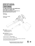
CAUSE
On/Off
control
intheSTOP
position
Turn On/Off control to ON
Primer
bulbwasn'tpressed
enough
Press primer bulb fully and slowly 10 times
Fouled
sparkplug
Replace or clean the spark plug
ACTION
iiiiiiiiiiiiii iiii! ii !i i ! ii!i!i!;! i !i !i ii!iiii iiii ! i ili
Engine is flooded
Pull starter rope repeatedly with throttle control fully
engaged and with the choke lever in Position 3
CAUSE
ACTION
Air filter is plugged
Replace or clean the air filter
improper carburetor adjustment
Adjust according to the Carburetor Adjustments section or take
to a Sears or other qualified service dealer for an adjustment
CAUSE
ACTION
Old gas
Drain gas tank and add fresh fuel
Plugged spark arrestor
Clean or replace spark arrestor
CAUSE
ACTION
Old gas
Drain gas tank and add fresh fuel
Plugged spark arrestor
Clean or replace spark arrestor
Mini tiller tines bound with dirt or grass
Stop the unit, switch the On/Off Stop Control to STOP, clean
and remove any debris binding the tines
CAUSE
ACTION
Oilfillplug/dipsticklooseormissingo-ring
Tighten oil fill plug/dipstick,
CAUSE
ACTION
Sparkpluggapistoosmall/close
If further
14
replace o-ring
Adjust gap to 0.025"
assistance
is required,
contact
your Sears or other qualified
service dealer.
Engine
Type.................................................................................
Displacement
................................................................................
IdleSpeedRPM................................................................................
Operating
RPM ................................................................................
Clutch
Type.........................................................................................
Ignition
Type.........................................................................................
On/Off
StopControl........................................................................
Valveclearance
(intake
andexhaust)................................................
SparkPlugGap............................................................................
Lubrication
.........................................................................................
Crankcase
OilCapacity
............................................................................
Fuel...............................................................................................
Carburetor
...............................................................................
Starter...........................................................................................
Muffler......................................................................................
Throttle.........................................................................................
FuelTankCapacity
................................................................................
Cultivating
PathWidth(Maximum)
...............................................................
Cultivating
Depth(Maximum)
...................................................................
Approximate
Weight
(nofuel).......................................................................
Air-Cooled,
4-Cycle
1.6cu.in.(26.2cc)
3,000-3,600
rpm
7,200-8,800
rpm
Centrifugal
Electronic
Positive
On/Off
Switch
0.003-0.006
in.(0.076-0.0152
mm)
0.025inch(0.635
mm)
SAE30Oil
3.04oz(90ml)
Unleaded
Diaphragm,
All-Position
AutoRewind
Baffled
withGuard
SpringReturn
18oz(532ml)
9 inches(22.86
cm)
6 inches(15.24
cm)
25lb.(11.5kg)
* Allspecifications
arebased
onthelatestproduct
information
available
atthetimeofprinting.
Wereserve
therighttomakechanges
at
anytimewithout
notice.
15
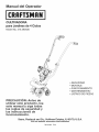
Manual
del Operador
CULTIVADORA
para Jardines de 4 Ciclos
Model No. 316.292630
o SEGURIDAD
MONTAJE
FUNCIONAMIENTO
MANTENIMIENTO
LISTADO DE PIEZAS
PRECAUCI6N:
Antes de
utilizar
este producto, lea
este manual y siga todas
las reglas de seguridad
y
las instrucciones
de
funcionamiento,
Sears,
Roebuck
and Co., Hoffman
Visit our website:
Estates, IL 60179, U.S.A.
www.sears.com/craftsman
769-04601
P00
INDICE DE CONTENIDOS
Llamadas a apoyo al cliente ......................
Normas para una operaci6n segura ................
Garantia ......................................
Conozca su unidad .............................
Instrucciones de ensamble .......................
Informaci6n del aceite y del gasolina ...............
Instrucciones de arranque y apagado ...............
Instrucciones de operaci6n .......................
Instrucciones de mantenimiento y reparaci6n .........
Limpieza y almacenamiento
.....................
Cuadro de soluci6n de problemas .................
Especificaciones
..............................
Lista de piezas ................................
Informaci6n de servicio .........................
E1
E2
E4
E5
E6
E7
E8
E9
E9
E13
E14
E15
E17
E20
PARACHISPAS
NOTA: Para los usuarios en tierras forestales de los EE.UU. yen
los estados de California, Maine, Oregon y Washington. Todos
los terrenos forestales de los EE.UU. y el estado de California
(C6digos de Recursos POblicos 4442 y 4443), Oregon y Washington,
requieren pot decreto, que ciertos motores de combusti6n interna
que se hagan funcionar en zonas boscosas y/o zonas cubiertas por
pastizales, esten equipados con un parachispas, que sean
mantenidos en buen estado de funcionamiento o que el motor sea
construido, este equipado y sea mantenido para evitar incendios.
Consulte los reglamentos pertinentes a esos requisitos con las
autoridades estatales o locales. El incumplimiento de esos requisitos
puede responsabilizarle o someterle a la imposici6n de una multa.
Esta unidad rue equipada en la fAbrica con un parachispas. Si
requiere sustituci6n, hay una PantaUa Parachispas disponible,
Pieza # 753-05297 al contactar el departamento de servicio.
PROPOSlCION 65 DE CALiFORNiA
Los simbolos de seguridad se utilizan para Ilamar su atenci6n
sobre posibles peligros. Los simbolos de seguridad y sus
explicaciones merecen toda su atenci6n y comprensi6n. Los
simbolos de seguridad no eliminan ningQn peligro por si mismos.
Las instrucciones o advertencias que ofrecen no substituyen las
medidas adecuadas de prevenci6n de accidentes.
SIMBOLO
J_,
L
_!
J
_!_lb
J
_!_h_
SIGNIFICADO
ALERTA
DE SEGURIDAD
: Indica peligro,
advertencia
para evitar sufrir
o precauci6n.
graves lesiones
Debe prestar
personales.
atenci6n
Puede
ser utilizado junto con otros simbolos o figuras.
PELIGRO
: El no obedecer una advertencia de
personas sufran
lesiones.
Siga siempre
seguridad
puede graves
conducir
a que usted
u otras las
precauciones de seguridad para reducir el riesgo de
incendio, descarga electrica y lesiones personales.
ADVERTENOIA
: El no seguir una advertencia
personas
sufran
lesiones.
Sigaasiempre
las u otras
e seguridad
puede
conducir
que usted
precauciones de seguridad para reducir el riesgo de
incendio, descarga electrica y lesiones personales.
PRECAUCION
: El no seguir una advertencia
de seguridad puede conducir a da_o patrimonial o
a que usted u otras personas sufran lesiones
personales. Siga siempre las precauciones de
seguridad para reducir el riesgo de incendio,
descarga electrica y lesiones personales.
REMARQUE: Le ofrece informaci6no instruccionesque son
esenciales para la operaci6n o mantenimiento del equipo.
LAS EMISIONES DEL MOTOR DE ESTE PRODUCTO
CONTIENEN SUBSTANCIAS QUIMICAS QUE EL ESTADO DE
CALiFORNiA CONOCE COMO CAUSANTES DEC ANCER,
DEFECTOS DE NACIMIENTO U OTROS DANOS
REPRODUCTIVOS.
Lea el manual del operador y siga todas las advertencias
e
instrucciones de seguridad. De no hacerlo, el operador y/o
los espectadores
pueden sufrir graves lesiones.
Si TIENE PREGUNTAS,
LLAME
AL
1-800-859-5917
Antes de que empiece a ensamblar su nuevo equipo, pot favor ubique la placa que contiene el modelo de la unidad y escriba esa
informaci6n en el espacio en blanco aqui debajo. Aqui debajo se explica la muestra de una placa del modelo.
N,umeroee
. sene
. Namero
..=, del modelo Namero .de la .
"_
\
pieza del f,_a_ricame
S!N;
Copie el n_mero
del modelo/pieza
del fabricante
aqui:
Copie el nQmero de serie aqui:
o IMPORTANTE INFORMACION
LEA TODAS LAS INSTRUCCIONES
UNIDAD
ANTES DE OPERAR LA
reglas de seguridad cuando use la unidad. Por favor
lea estas instrucciones
para su propia seguridad y
las de los espectadores,
antes de hacer funcionar la
I I
o
Los ninos y los adolescentes menores de 15 anos de edad no
deben usar la unidad. Los adolescentes pueden hacerlo bajo
la supervisi6n de un adulto.
Todos los dispositivos de protecci6n y los accesorios de seguridad
deben estar instalados adecuadamente antes de operar la unidad.
Inspeccione la unidad antes de usarla. Reemplace las piezas
danadas. Verifique si hay fugas de combustible. AsegQrese de que
todos los fljadores est6n en su lugar y asegurados. Reemplace las
piezas que esten agrietadas, astilladas o danadas en cualquier
forma. No opere la unidad con piezas sueltas o danadas.
Inspeccione cuidadosamente el Area antes de operar la
unidad. Elimine todos los escombros y los objetos duros o
filosos tales como cristal, alambre, etc.
"c";sede ese°ui"assi°uie°tes
unidad.
favorpara
mantenga
estas instrucciones
en
un
lugar Por
seguro
uso futuro.
• Lea las instrucciones cuidadosamente.
Familiadcese con los
controles y el uso adecuado de la unidad.
• No opere esta unidad cuando est6 cansado, enfermo o bajo la
influencia de alcohol, drogas o medicamentos.
E2
DE SEGURIDAD
• Est6 consciente del riesgo de lesi6n en lacabeza, lasmanos y los pies.
No permita ni_os, espectadores ni mascotas en el Area. Los
ninos, los espectadores y las mascotas deben estar fuera de
un radio de 50 pies (15 m.) como minJmo; de todas formas los
espectadores correrAn el riesgo de ser golpeados por objetos
lanzados por la unidad. Se debe exhortar a los espectadores
a que usen protecci6n para los ojos. Si se le acerca alguien
apague la unidad de inmediato.
Oprima el control del estrangulador y compruebe que regresa
automAticamente a la posici6n de marcha en vacio. Haga
todos los ajustes o reparacJones antes de usar la unidad.
AVISOS DE SEGURIDAD PARA LAS UNIDADES QUE
FUNCIONAN CON GASOUNA
AImacene el combustible solamente en recipJentes dise_ados
y aprobados especificamente para el almacenamiento de
sus gases pueden explotar si se encienden. Tome
ADVERTENCIA:
La gasolina es muy inflamable ]
lYassiguientes precauciones:
_
dJchos materiales.
• Evite crear una fuente de ignicJ6npara elcombustible derramado. No
arranque el motor hasta que se disipen los vapores del combustible.
• Pare siempre el motor y deje que se enfrie antes de Ilenar el
tanque de combustible. Nunca quite la tapa del tanque de
combustible, nJagregue combustible, cuando el motor est6
caliente. Nunca opere la unidad sin la tapa de combustible bien
colocada en su lugar. Afloje la tapa del tanque de combustible
lentamente para aliviar cualquier presi6n que haya en el tanque.
• Agregue el combustible en un Area exterior bien ventilada,
donde no haya chispas nJ llamas. Quite lentamente la tapa de
combustible s61o despues de haber parado el motor. No fume
mientras est6 Ilenando de combustible o mezclandolo. Limpie
de la unidad inmediatamente cualquJer combustible
derramado. Seque siempre la unJdad antes de usarla.
• Mueva siempre la unida a 30 pies (9.1 m) como minimo de la
fuente y sitio de combustible antes de arrancar el motor. No
fume nJ permJta chispas ni llamas expuestas cerca del Area
mientras est6 agregando combustible u operando la unidad.
CUANDO ESTE OPERANDO
• Nunca arranque ni opere la unidad dentro de un cuarto o edificio
cerrado. Respirar los vapores del escape puede ser fatal.
Opere esta unidad solamente en un Area exterior bJenventJlada.
• Use gafas protectoras que cumplan con la norma Z87.1-1989
de ANSi y tengan la marca que Io indic& Use protecci6n para
la oreja/audici6n cuando opere esta unidad. Use mascara
facial o para polvo si la operaci6n produce mucho polvo.
• Use pantalones largos fuertes, botas, guantes y camisa de
mangas largas. No use ropa holgada, joyas, pantalones
cortos, sandalias, ni est6 descalzo. AsegOrese el cabello pot
encima del nivel de los hombros.
• Esta unidad tiene un embrague. Las pOas permanece estacionario
cuando la unidad esta en marcha en vacio. Si no sucede asi, haga
que un t6cnico de servicio autorJzado ajuste la unidad.
• Antes de arrancar la unidad asegOrese de que las pOas no est6
en contacto con nada.
• Use la unJdad solamente de dia o con buena luz artificial.
• Evite arranques accidentales.
Est6 en la posici6n de arranque
cada vez que hale la cuerda de arranque. El operador y la
unidad deben estar en una posici6n estable al arrancar.
Consulte las Instrucciones de Arranque/Parada.
Use la herramienta correcta. Use esta herramienta solamente
para el prop6sito para el cual fue disenada.
Tenga mucho cuidado cuando invierta o mueva la unidad
hacia usted.
No se estJre demasJado. Mantenga siempre la base de apoyo
y equilJbrio adecuados. Tenga mucho cuidado cuando trabaje
en pendientes marcadas o inclinadas.
Sostenga siempre la unJdad con ambas manos cuando la
opere. Mantenga un agarre firme sobre ambas manijas.
Mantenga las manos, la cara y los pies alejados de todas las
partes en movimiento. No toque ni trate de parar los dientes
cuando est6n gJrando.
No toque el motor o el silenciador. Estas piezas estAn muy
calientes durante la operaci6n, incluso despues de que se
apaga la unidad.
No opere el motor a mAs velocidad de la necesaria para cuRivo. No
haga funcionar el motor a alta velocidad cuando no est6 cultivo.
Pare siempre el motor cuando deje de cultivo o cuando est6
caminando de un lugar de cultJvo hacia otro.
Si golpea o se enreda con un objeto extra,o, pare el motor
inmediatamente y verifique sJ ha habido algQn da_o. No Io
opere antes de reparar el dano. No opere la unidad con
piezas sueltas o danadas.
Pare la unidad, apague el motor y desconecte la bujia para
mantenimiento o reparaci6n.
Use solamente piezas y accesorios de reemplazo del fabricante
del equipo original para esta unidad. Estos estan disponibles
en su proveedor de servicio autorizado. El uso de cualquier
pieza o accesorio no autorizado podda causar lesiones graves
al usuario, o danos a la unidad, y anular su garanfia.
Mantenga la unidad limpia de vegetaci6n y otros materiales.
Pudieran quedar obstruidas entre las pQas y el protector.
Para reducJr el pelJgro de incendio reemplace un silenciador y
amortiguador de chispas defectuoso. Mantenga el motor y el
silenciador libre de hierba, hojas, exceso de grasa o
acumulaci6n de carb6n.
DESPUi_S DE USARLA
* Limpie las pQas con un limpiador casero para eliminar la
acumulaci6n de resina. Aceite las pOas con aceite de
maquina para evJtar la corrosi6n.
OTROS AVISOS DE SEGURIDAD
Nunca almacene una unidad con combustible dentro de un
edificio en el cual los vapores puedan Ilegar a una llama
expuesta o una chispa.
* Deje que el motor se enfde antes de almacenarlo o transportarlo.
Aseg@ese de fijar bJen la unidad mientras la transporta.
o Almacene la unJdad en un Area seca y cerrada, o en un lugar
alto para evitar uso no autorJzado o danos. Mant6ngala
alejada del alcance de los nJnos.
* Nunca rocJe ni chorree la unidad con agua ni nJngOnotro
liquido. Mantenga las manijas secas, limpias y libres de
escombros. LJmpiela despu6s de usarla, vea las instrucciones
de LimpJeza y AImacenamiento.
* Conserve estas instruccJones. ConsQItelas con frecuencJa y
Oselas para instruir a otros usuarios. Si le presta esta unidad a
alguien, pr6stele tambi6n estas instrucciones.
GUARDE
ESTAS INSTRUCCIONES
o SiMBOLOS
DE SEGURIDAD
E INTERNACIONALES
•
Este manual del operador describe los simbolos y figuras de seguridad e internacionales que pueden aparecer en este producto. Lea el
manual del operador para obtener informaci6n completa acerca de la seguridad, ensamble, operaci6n y mantenimiento y reparaci6n.
SJMBOLO
SIGNIFICADO
sJMBOLO
SIGNIFICADO
s MBOLO
DEALERTA
DESEGUR DAD
_,
Indica peligro, advertencia 0 precauci6n. Puede
I set utilizado junto con otros simb01os 0 figuras:
III T
III
I
le LEA EL MANUAL DEL OPERADOR
_hl ADVERTENCIA:
Leaei
manual dei oPerad0r
I III ysigatodaslasadvertenciaseinstrucciouesde
I seguridad. De no hacer!o, el operador y/o los
espectadores pueden sufrir graves lesiones.
1
I
I
I
I
J
I
ENCEND DO/ARRANQUE/MARCHA
i i
• CONTROL DE ENCENDIDO Y APAGADO
o CONTROL DE ENCENDIDO Y APAGADO
APAGADO o PARADO
1 2 3 _' CONTROL DEOBTURADOR
I--I I_'1 I{ I 1 _,Pos c 6n de obturac 6n COMPLETA
2, Posici6n de obturaci6n PARClAL
3 o Pos c 6n de MAROHA
E3
USE PROTECCION
'_
Use siempre combustible
i_ilp_ _
"cOMBUSTIBLESINPLOMO.
L,_
plomo.
° ND OADOR
DEACEn'E
"
Consu!te el manual del operador para obtener
" informaci6n acerca dei tipo correcto de aceitel
OCULAR Y AUDITWA
Los objetos arrojados per la
unidad y el ruido fuerte pueden causar graves
lesiones oculares y p6rdida auditiva. Utilice
proteccbn ocular que cumpla con las normas ANSI
Z87.1-1989 y proteccbn auditiva cuando opere esta
unidad. Use una careta completa cuando la necesite.
ADVERTENCIA:
!impio, nuevo y sin
"
ADVERTENClA:
Mantenga a todos 10s
• MANTENGA
ESPECTADORES
espectadores, ALEJADOS
en especialA aLOS
niSos
y animales
dom6sticos a porio menos 50 pies (!5 m) de!
' Area de cortel
• LOS OBJETOS DESPEDIDOS Y LA CUCHILLA
I
ROTATWA PUEDEN CAUSAR GRAVES LESIONES I
ADVERTENCIA:
No opere esta unidad Si la I
protecci6n piAstica de iinea no estA colocada en I
su !ugar. Mant6ngase aieJad0 de! acces0rio de
I
corte giratorio.
I
,,,,,,,,,,,,,,,,,,,,,,,,,_
ADVERTENCIA:
No toque
un silenciador
ni
un ciiindro caliente Puede
quemarse.
Estas partes
lo se
SUPERFICIE
calientan mucho
DE CALIENTE
con el use. Luego de apagarse 1
permanecen caiientes durante un corto tiem po.
• CULTWADORES PARA JARDINES - Las puas
giratorias pueden causar graves lesiones
ADVERTENCIA:
Apague el motor y espere
que ias pOas se detengan antes de instaiar o
sacar las pleaS, Oantes de realizar ia lirn pieza o
todo tipo de mantenimiento.
Mantenga las
manos y los pies lejos de ias pOas giratorias.
GARANTIA LIMITADA DE DOS AhlOS DE CRAFTSMAN
Si este producto Craftsman, operado y mantenido segOn todas [as instrucciones provistas, faiia debido a un defecto en el material o en
[a mano de obra dentro de un perbdo de dos anos a partir de [a fecha de compra, [[6veloa cuaiquier tienda Sears, u otto
estabiecimiento de Craftsman autorizado en Estados Unidos para que sea reparado sin costo aiguno.
Para el estabiecimiento autorizado mAs cercano, [lame al 1-800-4-MY-HOME®.
Esta garantia tiene vigencia soiamente pot 90 dias a partir de [a fecha de compra si este producto se usa para fines comerciaies o de
alquiler.
Esta garantia abarca SOLAMENTE los defectos en el material o en la mano de obra. Sears NO pagarA pot:
* Los articulos no reutilizables que se desgasten debido al uso normal, incluyendo entre otros, cuchillas, dientes o correas.
* El reempiazo o reparaci6n de neumAticos o ruedas que resuite del desgaste normal, accidente u operaci6n o mantenimiento no
apropiados.
* Las reparaciones necesarias debido a maltrato por parte del operador, incluyendo entre otros, dafos ocasionados pot impactos de
objetos que doblen el bastidor o el cigOefal del motor.
* Reparaciones necesarias debido a negligencia del operador, inciuyendo entre otros, dafos mecAnicos y electricos ocasionados pot un
aimacenamiento no apropiado, o no haber dado mantenimiento al equipo de acuerdo con [as instrucciones contenidas en el manual
de[ operador.
* Las reparaciones necesarias debido a mezcla incorrecta de combustible, combustible contaminado o viejo.
* Deterioro y desgaste normal de los acabados exteriores, o reemplazo de [a etiqueta del producto.
Esta garantia se aplica solamente mientras este producto est6 en Estados Unidos.
Esta garantia [e confiere a usted derechos [egaies especificos y usted puede tenet otros derechos que varian de un estado a otto.
Sears, Roebuck and Co., Hoffman Estates, IL 60179
Convenio de Protecci6n de Reparaci6n
Felicidades por haber realizado una compra inteligente. Su nuevo producto Craftsman® esta disefado y fabricado para ofrecerle afros
de funcionamiento confiable. Pero como todos los productos, es posible que sea necesario repararlo de vez en cuando. Ahi es
cuando tener un Convenio de Protecci6n de Reparaci6n puede ahorrarle dinero y problemas.
Esto es Io que incluye el Convenio de Protecci6n de Reparaci6n*:
[]
Servicio experto de nuestros 10,000 especialistas profesionales en reparaciones
[]
Servicio iiimitado y sin costo alguno pot piezas y mano de obra en todas las reparaciones cubiertas
[]
Reemplazo del producto per un valor de hasta $1500 si el producto cubierto no se puede reparar
[]
Descuento del 10% en el precio regular del servicio, asi como de las piezas instaladas, que el convenio no cubra; igualmente,
10% de descuento en el precio regular de comprobaci6n de mantenimiento preventivo
[]
Ayuda rApida por tel_fono - la Ilamamos Soluci6n Rapida - asistencia tecnica per telefono de un representante de Sears.
Piense en nosotros como si fueramos un "manual del usuario que habla".
Una vez que adquiera el Convenio de Protecci6n de Reparaci6n, todo Io que necesita es hacer una simple Ilamada para programar el
servicio de reparaci6n. Puede Ilamar a cualquier hora del dia o de la noche, o hacer una cita de servicio per Internet.
El Convenio de Protecci6n de Reparaci6n es una compra libre de riesgo. Si usted cancela pot cualquier motivo durante el periodo de
garantia del producto, proporcionaremos un reembolso completo. O, un reembolso prorrateado en cualquier momento despues de que
venza el periodo de garantia del producto, iAdquiera hoy mismo su Convenio de Protecci6n de Reparaci6n!
Aplican algunas limitaciones y exciusiones. Para obtener precios e informaci6n adicional en los Estados Unidos, Hame al 1-800-827-6655.
*La cobertura en Canada var{a en algunos art{culos. Para obtener todos los detalles, llame a Sears en Canada al 1-800-361-6665.
Servicio de Instalaci6n Sears
Para la instalaci6n de electrodomesticos,
abridores de puertas de garaje, calentadores de agua, y otros productos para el hogar por
profesionales de Sears, en los Estados Unidos o CanadA, Ilame al 1-800-4-MY-HOME®.
E4
APLICAClONES
• Cultivar
tierraherbosa
ytierranegraligera
a mediana.
• Cultivar
Areas
dejardines,
alrededor
deb_rboles, etc.
APAGADO
(O)
• Recortar los bordes.
ENCENDIDO
Control del
regulador
Bombilla
del cebador
Perillas del
manubrio
Manubrio
Silenciador
Mango de la
cuerda de arranque
Protecci6n
de las pQas
Control del
obturador
de
Soporte dela
Rueda
P_as
Rueda de la Bordeadora
Rueda y de la Cuchilla de la Bordeadora
Opcion&l 292670
E5
NOTE:
Desde la posici6n de funcionamiento, se observa la
referencia a la derecha o a la izquierda de la
cultivadora / bordeadora.
COLOOACION DEL MANUBRIO
1. Afloje las dos perillas del lado interior del manubrio (Fig. 1).
Manubrio
CONEXION DE LA RUEDA Y DE LA CUCHILLA
BORDEADORA OPCIONAL
Para convertir la cultivadora en una bordeadora, siga los
siguientes pasos:
1. Presione el interruptor encendido / apagado (©) para
detener el motor y los dientes y desconecte la bujia para
evitar un arranque accidental.
NOTA:
Perno
Perilla del
manubrio
2.
Orificio
Arandela
3.
Fig. 1
2.
Con la unidad en posici6n vertical, gire el manubrio hacia
arriba hasta la posici6n de operaci6n (Fig. 2).
4.
5.
Es posible que sea necesario ubicar la cultivadora/
bordeadora en posici6n horizontal en una superficie
plana con la manija superior tocando el suelo
Extraiga la chaveta del trinquete de cada extremo del _.rbol
del diente y deslice los dientes hasta extraerlos del _.rbol.
Deslice la rueda de la bordeadora, con el buje mirando
hacia adentro, en el lado derecho del _.rbol del diente y
asegOrelo con la chaveta de trinquete en el orificio interior
(Fig. 4).
Deslice la cuchilla de la bordeadora con el buje mirando
hacia el lado izquierdo del _.rbol del diente y asegOrelo con
la chaveta de trinquete en el orificio interior (Fig. 4).
Deslice la cuchilla de la bordeadora a Io largo del cantero,
jardin, vereda o entrada con la rueda de la bordeadora a Io
largo del borde exterior.
Ru a de la
e_d
Bordeadora
NOTA:
Tenga cuidado de no pellizcar el cable del regulador o
los cables del interruptor cuando coloque el manubrio.
3. Ajuste las perillas para asegurar el manubrio en su lugar.
NOTA: No ajuste las perillas demasiado.
4. Vuelva a conectar la bujia de encendido.
AJUSTE DE LA PROFUNDIDAD
Para ajustar la m6nsula de soporte de la rueda proceda de la
siguiente manera:
1. Detenga el motor y desconecte la bujia para evitar un
arranque accidental.
2. Extraiga la chaveta de reten de la chaveta de horquilla y
deslice la chaveta hasta extraerla de la mensula de la
pieza posterior (Fig. 3).
3. Deslice la mensula de soporte de la rueda hacia arriba o
hacia abajo en la pieza posterior, alineando los orificios a
la altura deseada.
4. Ubique la chaveta de la horquilla a traves del orificio y
asegOrelo con una chaveta de reten.
Chaveta de
Horquilla
Pasador de
Chaveta
de la
Pieza Posterior
Fig. 3
Buje
Chaveta
Cuchilla de la
Bordeadora
Fig. 2
E6
DE LA
._/Trinqueta
Fig. 4
de
ADVERTENClA:
EL LLENAR DEMASIADO EL
CARTER PUEDE CAUSAR LESIONES
PERSONALES GRAVES No podemos exagerar la
importancia del control y mantenimiento del nivel
correcto de aceite en el cigQer_al. Verifique el aceite
antes de cada uso y cambielo cuando sea necesaric
segQn se indica en la secci6n de Cambio del aceite.
TIPO DE ACEITE RECOMENDADO
El uso de un aceite del tipo y peso correctos en el cigQer_al es
extremadamente importante. Verifique el aceite antes de cada
uso y cambie el aceite con frecuencia. Si no usa el aceite
correcto, o utiliza aceite sucio, puede causar el desgaste y falla
prematuros del motor.
Use un aceite de buena calidad SAE 30 de API (American
Petroleum Institute) clase de servicio SG, SF, SH.
CARGA EACErrE EN EL CARTER DEL CIGOEI_IAL: USO INICIAL
NOTA: Esta unidad se envia sin carga
de aceite. A fin de evitar el dar_o
de la unidad, cargue aceite en el
carter del cigQer_al antes de
intentar arrancar la unidad.
Su unidad trae una botella de aceite SAE 30 SF,
SG, SH de g0 ml (3,04onzas fluidas) (Fig. 5).
NOTA: Guarde la botella para medir la
cantidad correcta de aceite
cuando deba cambiarlo en el
Fig. 5
futuro. Lea Cambio de Aceite.
1. Desenrosque la tapa de la botella de aceite y retire el sello
de papel que cubre la apertura. Vuelva a colocar la tapa.
Corte la punta de la boquilla del embudo (Fig. 5).
2. Coloque la unidad sobre una superficie plana (Fig. 6).
Tap6n de relleno
de aceite/, varilla
NOTA:
No agregue nunca aceite al gasolina o al tanque de
gasolina.
5. Limpie todo el aceite que pueda haberse derramado y
vuelva a instalar el tap6n del aceite / varilla de medici6n.
No podemos exagerar la importancia del control y
mantenimiento del nivel correcto de aceite en el cigQenal.
Verifique el aceite antes de cada uso y c_,mbielo cuando sea
necesario segOn se indica en la secci6n de Cambio del aceite.
TIPO DE GASOLINA RECOMENDADO
La gasolina viejo es lacausa principal del real funcionamiento de la
unidad. AsegOrese de usar gasolina nueva, limpio y sin plomo.
NOTA: Este es un motor de cuatro ciclos. Para evitar da_ar su
unidad, no mezcle el aceite con la gasolina.
Definici6n de los gasolinas de mezcla
Las gasolinas actuales con frecuencia son una mezcla de gasolina y
uno o mAs oxigenantes como el etano, el metanol o el MTBE (6ter).La
gasolina con mezcla de alcohol absorbe agua. Un porcentaje de agua
tan pequer_ocomo el 1% en lagasolina puede hacer que la gasolina y
el aceite se separen. Se forman acidos mientras estA guardado.
Cuando use gasolina con mezcla de alcohol, use gasolina nueva
(almacenado durante menos de 60 dias).
Uso de los gasolinas de mezcla
Si decide usar un gasolina de mezcla o si su uso es inevitable, le
recomendamos que tome las siguientes precauciones:
* Use siempre una mezcla fresca de gasolina segOn Io indica su
manual del operador
* Use Sta-Bil® o su equivalente
* Drene el tanque y haga funcionar el motor en seco antes de
guardar la unidad
Uso de aditivos en la gasolina
El uso de aditivos en la gasolina, como Sta-Bil® o similar,
inhibirAla corrosi6n y reducir_, la formaci6n de dep6sitos de
goma. El uso de aditivos puede evitar que se formen dep6sitos
daninos en el carburador por hasta ocho (8) meses. Agregue 23
ml (0,8 de onza) de aditivo por gal6n de gasolina de acuerdo a
las instrucciones del envase. No agregue NUNCA los aditivos
directamente al tanque de gasolina de la unidad.
CARGA DE COMBUSTIBLE
_
Fig. 6
3. Saque el tap6n de aceite/varilla de medici6n del cigQer_al(Fig. 7).
EN LA UNIDAD
lentamente para evitar lesionarse con el rociado de
la DVERTENClA:
gasolina. No opere Saque
nunca la
unidad
la tapa de
la tapa
delsin
gasolina
la gasolina firmemente colocada en su lugar.
1. Saque la tapa de la gasolina.
I'1
ADVERTENCIA:
Cargue el gasolina en un _,rea
exterior limpia y bien ventilada. Limpie de inmediato
todo gasolina que se haya derramado. Evite crear
una fuente de encendido con la gasolina derramado.
No arranque el motor hasta que se hayan evaporado
los gases de la gasolina.
Tapbn de
relieno de
aceite/varilla
de medici6n
NOTA:
Llene o armadagasolina al tanque Qnicamente cuando el
cultivador este en posici6n horizontal (Fig. 9).
Anillo en "O"
Orificio de
llenado de aceite
J
Fig. 7
4. Vierta todo el contenido
(Fig. 8).
de la botella de aceite en el cigQe_al
:\
Orificio de
llenado de
aceite
Fig. 8
Fig. 9
2. Coloque el pico del recipiente de gasolina en el orificio de
Ilenado del tanque de gasolina y Ilene el tanque.
NOTA: No Ilene el tanque demasiado.
3. Limpie toda la gasolina que pueda haberse derramado
4. Vuelva a instalar la tapa de la gasolina.
5. Mueva la unidad por Io menos 9,1 m (30 pies) de la fuente y
sitio de carga antes de arrancar el motor.
NOTA: Elimine la gasolina vieja de acuerdo a los reglamentos
federales, estatales y locales.
E7
ENCENDIDO
(I)
APAGADO
(O)
Area exterior bien ventilada. Los gases de escape
de mon6xido de carbono pueden ser letales en un
I ADVERTENClA:
Use esta unidad s61o en un
Area cerrada.
__
ADVERTENCIA:
Evite los arranques
accidentales. Col6quese en posici6n de inicio
cuando tire de la cuerda de arranque (Fig. 12). El
operador y la unidad deben estar en una posici6n
estable al arrancar la unidad para evitar graves
lesiones personales.
INSTRUCCIONES
1.
2.
3.
4.
5.
6.
Control del
regulador
DE ARRANQUE
Verifique el nivel de aceite en el carter del cigQedal. Lea
Inspeccidn del Nivel de Aceite.
Llene el tanque de combustible con gasolina nueva, limpia
y sin plomo.
Coloque el Control de Encendido/Apagado (On/Off) en la
posici6n de ENOENDIDO (ON) [I] (Fig. 10).
Coloque la palanca del obturador en Posici6n 1.
Optima completamente el cebador y sueltelo 10 veces.
Hagalo lentamente. Se debera vet un poco de combustible
en el cebador yen las tuberias de alimentaci6n de
combustible (Fig. 11). Si no puede ver el combustible en el
cebador, oprimalo y sueltelo tantas veces como sea
necesario hasta que vea combustible en el mismo.
Sostenga el regulador y la agarradera con una mano y
agarre el cord6n de arranque con la otra mano. Use el pie
para aguantar el cultivador (Fig. 12).
Incline la unidad ligeramente hacia atras para levantar
las pOas del suelo al arrancar.
7. Mientras oprime el control del regulador, tome el mango de
la cuerda de arranque y hale el cord6n de arranque con un
movimiento controlado y uniforme hasta 5 veces.
8. Coloque la palanca del obturador en Posici6n 2.
9. Mientras oprime el control del regulador, tire de la cuerda
de arranque de 1 a 4 veces hasta que el motor arranque.
Dejelo funcionar de 30 a 60 segundos.
10. Coloque la palanca del obturador en Posici6n 3. Suelte el
control del regulador a la posici6n de minima y comience la
operaci6n.
SI... El motor no arranca, regrese al pasos 4-11.
Fig. 10
Control
t
del
II
f<
Posici6n 2 = Posicidn 3
NOTA:
Sl...
El motor no arranca despues de varios intentos, coloque
la palanca del obturador en la Posici6n 3 y oprima el
control del regulador. Hale la cuerda del arranque con
fuerza de 3 a 8 veces. El motor debera arrancar. Si no
sucede asi, repita el procedimiento.
Bombilla de
encendido
Fig. 11
Mango de la
cuerda de
arranque
del
regulador
Sl SE CALIENTA... El motor ya esta caliente, cerci6rese de
que el control de Encendido/Apagado
este en la posici6n
de Encendido [ON] y arranque la unidad con la palanca
del obturador en la Posici6n 2. Despues de que la unidad
arranque, mueva la palanca del obturador a la Posici6n 3.
INSTRUOOIONES DE APAGADO
1.
Saque la mano del control del regulador. Deje enfriar el
motor en minima.
2.
Coloque el control de Encendido/Apagado
APAGADO (O)(Fig. 10).
E8
en posici6n de
Fig. 12
CONSEJOS
PROGRAMA
PARA LA OPERACION
ADVERTENClA:
Vista en forma adecuada para
reducir el riesgo de lesiones cuando opere esta
unidad. No use ropa holgada ni alhajas. Use
protecci6n ocular y auditiva. Use pantalones largos
y gruesos, botas y guantes. No use pantalones
cortos, sandalias ni trabaje descalzo.
Mueva el cultivador al Area de trabajo antes de arrancar el
motor. Puede transportar el cultivador empujandolo sobre
las ruedas o Ilevandolo del tubo central de la manija.
personales, nunca levante ni transporte la unidad
DVERTENClA:
Para evitar graves lesiones
con
el motor en marcha.
_
2.
3.
4.
5.
6.
7.
j
Arranque la unidad siguiendo las instrucciones de arranque.
Con el motor en marcha y las pOas sin tocar el suelo,
optima el control del regulador para aumentar la
velocidad del motor.
Mientras que sostiene la manija superior con ambas
manos, baje lentamente el cultivador hasta que las pOas
hacen contacto con el suelo (Fig. 13).
A medida que comienza el cultivo, incline el cultivador
ligeramente usando los manubrios de modo que las pOas
puedan penetrar en la tierra.
Una vez que se ha abierto la tierra, continOe a un ritmo
moderado hasta que conozca bien los controles y el
manejo del cultivador.
Si las pOas estAn cavando con una profundidad excesiva
o insuficiente, ajuste el soporte de la rueda de acuerdo a
la secci6n de Ajuste de la Profundidad de las POas.
personales, tenga mucho cuidado cuando invierta o
DVERTENClA:
Para evitar graves lesiones
j
gire
la unidad hacia usted.
_
DE MANTENIMIENTO
graves, nunca realice mantenimiento ni reparaciones
con la unidad funcionando. Realice siempre el
mantenimiento y las reparaciones con la unidad fria.
_
DVERTENClA:
Para
evitar de
lesiones
personales
Desconecte
el cable de
la bujia
encendido
para
cerciorarse de que la unidad no arrancar&
Estos procedimientos requeridos para el mantenimiento deben
ser reaNzados con la frecuencia indicada en la tabla. Deben ser
incluidos como parte de toda puesta a punto de cada temporada.
NOTA: Algunos procedimientos de mantenimiento pueden
requerir el uso de herramientas o habilidades especiales.
Si no estA seguro acerca de estos procedimientos, Ileve
su unidad a un establecimiento de reparaci6n, persona o
distribuidor de servicio autorizado que arregle motores
para uso fuera de la carretera.
NOTA: El mantenimiento, la sustituci6n o arreglo de
dispositivos para el control de emisiones y sistemas
pueden ser hechos pot cualquier establecimiento de
reparaci6n, persona o proveedor de servicio autorizado
que arregle motores para uso fuera de la carretera.
FRECUENCIA
MANTENIMIENTO
REQUERIDO
Antes de
Llene el tanque de combustible
combustible nuevo
arrancar el motor Inspeccione el aceite
Cada 10 horas
Primer cambio
alas 10 horas
VEA
con
F7
F10
Limpie y vuelva a aceitar el filtro de aire
F10
Cambie el aceite
F10
Cada 25 horas
Cambie el aceite
Limpie el amortiguador
Cada 25 horas
Verifique la condici6n y separaci6n de
la bujia de encendido
de chispas
F10
F13
F13
REMOCION Y REPOSICION DE LAS PUAS
Las 4 pQas deben cambiarse al mismo tiempo debido a que se
desgastaran en forma pareja con el uso normal. Trabaje en un
lado por vez.
I _lb
personales, use siempre guantes gruesos cuando
! ADVERTENOIA-"
Para evitar graves lesiones
maneje las pOas.
!
1. Coloque el control de encendido y apagado en la posici6n de
APAGADO (O) y desconecte el cable de la bujia de encendido.
NOTA: Puede ser necesario colocar la cultivadora en posici6n
horizontal sobre una superficie plana con la manija
superior tocando el suelo
2. Saque las presillas del pasador de la horquilla y los
pasadores de la horquilla (Fig. 14).
Fig. 13
Transporte
_
1.
2.
3.
de la Unidad
personales, apague siempre el motor cuando
demote
la operaci6n oPara
mientras
la unidad
DVERTENCIA:
evitar transporta
graves lesiones
entre Areas de trabajo.
Apague el motor.
Incline la unidad hacia atras hasta que las pOas desmalezan
la tierra.
Empuje o Ileve launidad hasta el pr6ximo lugar que deba cultivar.
Diente
"B"
Bujes
Chaveta de
Trinqueta
Fig. 14
3. Limpie y aceite el eje.
4. Deslice los nuevos dientes con el buje mirando hacia afuera.
Los cuatro dientes estan marcados con letras A y B.
E9
5. Ubique un diente A y un diente Ben el arbol del diente (Fig. 13).
6. Asegure los nuevos dientes al arbol con chavetas de trinquete.
INSPECCION
DEL NIVEL DE ACEITE
excesivo del motor
siempre el nivel de
cigQer_al.
No opere
RECAUCl6N:
debajo del extremo
_
y el dar_o de la unidad, mantenga
aceite correcto en el carter del
nunca
la unidad
con el aceite
Para evitar
un desgaste
inferior de la varilla de medici6n.
No podemos exagerar la importancia de verificar y mantener el
nivel correcto de aceite en el carter del cigQer_al. Inspeccione el
nivel de aceite antes de cada uso:
1. Apague el motor y permita que el aceite drone dentro del
carter del cigQer_al.
2. Coloque la unidad en posici6n horizontal y nivelada para
obtener una lectura correcta del nivel de aceite (Fig. 9).
3. Mantenga la suciedad, recortes de cesped, etc. fuera del
motor. Limpie el Area alrededor del tap6n de relleno de
aceite / varilla de medici6n antes de retirarlo.
4. Retire el tap6n de relleno de aceite / varilla de medici6n y
seque el aceite. Vuelva a insertarlo completamente hacia
adentro.
5. Retire el tap6n de relleno de aceite / varilla de medici6n e
inspeccione el nivel del aceite. El aceite debe Ilegar hasta
la parte superior de la varilla de medici6n (Fig. 15).
CAMBIO DEL ACEITE
En un motor nuevo, cambie el aceite despues de las 10 primeras
horas de operaci6n. Cambie el aceite mientras el motor aOn estA
caliente. El aceite fiuira con libertad y Ilevara mas impurezas.
1. Desenchufe el manguito de la bujia de encendido para
_
2.
3.
1
lesiones cuando maneje la unidad.
PRECAUCION:
Use guantes para evitar sufrir
eliminar el arranque.
Retire el tap6n de relleno de aceite / varilla de medici6n.
Vierta el aceite fuera del orificio de Ilenado de aceite en un
recipiente inclinando la unidad hasta una posici6n vertical
(Fig. 17). Deje suficiente tiempo como para completar el
drenaje.
Tapbn de relleno de aceite
/ varilla de medicibn
Anillo en O
Fig. 17
Lleno
4.
Agregue
41-44 ml
(1,4-1,50nzas)
\
Parte superior de la
varilla de medici6n
Fig. 15
6.
Si el nivel esta bajo, agregue una peque_a cantidad de aceite
en el orificio de Ilenado de aceite y vuelva a medir (Fig. 16).
Repita hasta que el nivel de aceite Ilegue hasta la parte
superior de la varilla de medici6n.
NOTA: No Ilene demasiado la unidad.
Seque todo el aceite residual de la unidad y limpie todo el
aceite que pueda haberse derramado. Elimine todo el
aceite de acuerdo con las normas federales, estatales y
locales.
5. Vuelva a cargar el carter del cigQer_al con 90 ml (3,04
onzas fluidas) de aceite SAE 30 SF, SG, SH.
NOTA: Use la botella y la boquilla que guard6 del uso inicial
para medir la cantidad correcta. El nivel de 90 ml
(3,04 onzas) esta aproximadamente en la parte
superior de la etiqueta de la botella (Fig. 18). Mida el
nivel con la varilla de medici6n. Si el nivel esta bajo,
agregue una pequer_a cantidad de aceite y vuelva a
medir (Fig. 18). No Io Ilene demasiado.
|
|
I|
I
|
|
|
I
I
|
|
|
Tap6n de
relleno de
aceite/varilla
de medici6n
Ilenado
4-Cyde
Motor
Oil
Nivel
Fig. 18
Orificio de
llenado de aceite
Fig. 16
NOTA:
EIO
Verifique que el anillo en O este en su lugar en el tap6n
de relleno de aceite / varilla de medici6n cuando mida
y cambie el aceite (Fig. 16).
6.
Vuelva a colocar el tap6n de relleno de aceite / varilla de
medici6n.
7.
Vuelva a conectar el manguito de la bujfa de encendido.
de
MANTENIMIENTO
_
DEL FILTRO DE AIRE
personales, apague siempre su recortador y espere
que
se enfrie antes dePara
limpiarlo
realizarlesiones
todo tipo
evitar ograves
deDVERTENClA:
mantenimiento.
Limpieza del fiitro de aire
Limpie y vuelva a aceitar elfiltro de aire cada 10 horas de operaci6n.
Es un elemento cuyo mantenimiento es importante. Si no realiza el
mantenimiento del filtro de aire, su garantia sera ANULADA.
1. Abra la cubierta del filtro de aire. Empuje la orejeta del
lado izquierdo de la cubierta hacia adentro, gire la cubierta
del filtro de aire hacia afuera y separela del bastidor del
filtro de aire (Fig. 19).
2. Saque el filtro de aire y la pantalla que esta detras del
mismo (Fig. 19).
Tornillo de Palanca del obturador
filtro de aire
Pantalla
Filtro de aire
Cubierta
Fig. 21
8.
Gire la cubierta hacia la izquierda hasta que la orejeta de la
cubierta del filtro de aire se trabe en su lugar en la ranura
del lado izquierdo del bastidor del filtro de aire (Fig. 19).
AJUSTE DEL CARBURADOR
La velocidad minima del motor puede ser ajustada. Puede tener
acceso al tornillo de ajuste de minima a traves de un orificio en
la parte superior de la cubierta del motor (Fig. 22).
NOTA: Los ajustes descuidados pueden da_ar su motor
seriamente. Los ajustes del carburador deben set
realizados por un proveedor de servicio autorizado.
del filtro de aire
Ganchos
Bastidor del
filtro de aire
Filtro de aire
Fig. 19
3,
Lave el filtro con agua y detergente (Fig. 20). Enjuague
bien el filtro y dejelo secar.
Fig. 22
Inspecci6n del Combustible
En general, el combustible viejo es el motivo principal para que
la unidad no funcione en forma adecuada. Drene y vuelva a
Ilenar el tanque con combustible nuevo, limpio y sin plomo
antes de hacer ningOn ajuste. Consulte la Informacidn acerca
del Aceite y Combustible.
Limpieza del Filtro de Aire
los ajustes del carburador. Use ropa que Io proteja y_
II
para prevenir graves lesiones personales.
J
La condici6n del filtro de aire es importante para el funcionamiento
de la unidad. Un filtro de aire sucio limitarb_
el flujo de aire y
cambiar_, la mezcla de aire y combustible. Con frecuencia esto se
confunde con un carburador fuera de ajuste. Inspeccione la
condici6n del filtro de aire antes de ajustar el tornillo de velocidad
minima. Consulte la secci6n de Mantenimiento del Filtro de Aire.
Ajuste dei Tornillo de Velocidad M{nima
Si despu6s de inspeccionar el combustible y limpiar el filtro de
aire el motor aOn no funciona en minima, ajuste el tornillo de
velocidad minima segOn se indica a continuaci6n.
1. Arranque el motor y dejelo funcionar a una minima alta
durante un minuto para que se caliente.
NOTA: Verifique que las pOas no esten en contacto con el
suelo cuando ajuste la marcha lenta.
2. Suelte el gatillo del regulador y deje que el motor funcione en
marcha lenta. Si el motor se para, inserte un peque5o
cumpla con todas las La
instrucciones
de seguridad
ADVERTENClA:
unidad funcionara
durante
Fig. 20
Aplique suficiente aceite limpio de motor SAE 30 para
recubrir ligeramente el filtro (Fig. 21).
5,
Apriete el filtro para esparcir y retirar el exceso de aceite (Fig. 21).
6. Vuelva a colocar el filtro (Fig. 19).
NOTA: Si opera la unidad sin el filtro de aire, su garantia sera
ANULADA.
7. Vuelva a instalar la cubierta del filtro de aire. Coloque los
ganchos del lado derecho de la cubierta del filtro de aire dentro
de las ranuras del lado derecho del bastidor del filtro de aire.
4,
Ell
destornillador
Phillips
o devastago
pianoenelorificio
dela
cubierta
delsilenciador
/ filtro de aire (Fig. 22). Gire el tornillo
de marcha lenta en sentido horario, de a 1/8 de vuelta pot vez
(segQn sea necesario) hasta que el motor funciona en minima.
NOTA: Las p_as no deben girar cuando el motor esta en minima.
3. Si las pOas giran cuando el motor esta en minima, gire el
tornillo de marcha lenta en sentido antihorario 1/8 de vuelta
por vez (segQn sea necesario) para reducir la marcha lenta.
La inspecci6n del combustible, la limpieza del filtro de aire y el
ajuste del tornillo de velocidad minima debe resolver la mayor[a
de los problemas del motor. Si esto no sucede, y:
* El motor no funciona en minima
* El motor fluctOa o se ahoga al acelerarlo
* Existe una p6rdida de fuerza motriz
Ileve el carburador a ajustar a un proveedor de servicio autorizado.
HUELGO DEL BRAZO OSCILANTE
Para ajustar el espacio libre del brazo oscilador se requiere
desarmar el motor. Si usted siente que no est&.seguro o que no
estb_calificado como para realizar esto, Ileve la unidad a un
centro de servicio autorizado.
NOTA: Inspeccione el huelgo de la valvula del brazo oscilante con
una galga despues de las primeras 10 horas de operaci6n
y luego cada 25 horas de operaci6n en Io sucesivo.
* El motor debe estar fdo cuando verifique o ajuste el huelgo de
la vbdvula.
Esta tarea debe set realizada en interiores, en un b_realimpia y
[[bre de polvo.
1. Quite los cinco (5) tornillos con un destornillador de pala o
Torx #20 (Fig. 23).
Cubierta del
motor
1"-20
tornillos
4.
5.
6.
Limpie la suciedad de alrededor de la bujia de encendido.
Saque la bujia de encendido de la cabeza del cilindro girando
un casquillo de 16mm (5/8 pulgadas) en sentido antihorario.
Saque la cubierta del motor.
Limpie la suciedad de alrededor de la cubierta del brazo
oscilante. Saque el tornillo que sostiene la cubierta del
brazo oscilante con un destornillador grande de vastago
piano o con una broca Torx T-25 (Fig. 25). Saque la
cubierta y la junta del brazo oscilante.
Cubierta
del brazo
osciiante
X
Orificio de la
bujia de
encendido
Fig. 25
7.
Tire lentamente de la cuerda de arranque para traer el
pist6n hacia la parte superior de su recorrido (conocido
como punto muerto superior). Verifique que:
• El pist6n se encuentre en la parte superior de su recorrido
mientras mira dentro del orificio de la bujia de encendido (Fig. 26).
Brazos
oscilantes
de ajuste
ENTRADA
ESCAPE
Siienciador
Galga
Fig. 26
Fig. 23
2.
Saque el tornillo con un destornillador
(Fig. 24).
de pala o Torx #25
"1"-25Torniilo J
S
Fig. 24
3.
E12
Desconecte
el cable de la bujia de encendido.
Ambos brazos oscilantes se mueven con libertad, y ambas
vbJvulas estb_ncerradas
De no ser asi, repita este paso.
8. Deslice la galga entre el brazo oscilante y el resorte de
retorno de la valvula. Mida el huelgo entre el vastago de la
valvula y el brazo oscilante (Fig. 26 y 27). Realice esto en
las valvulas de entrada y de escape.
El huelgo recomendado para las vbdvulas de entrada y de escape
es 0,076 - 0,152 mm (0,003 - 0,006 pulgadas). Use un calibrador
regular de autom6vil de 0,127 mm (0,005 pulgadas). El calibrador
debe deslizarse entre el balancin y el vb_stagode la vbJvula con
una ligera cantidad de resistencia, sin doblarse (Fig. 26 y 27).
9.
Si el huelgo no se encuentra dentro de las especificaciones:
a. Gire la tuerca de ajuste con una Ilave de 8 mm (5/16
pulgadas) o una guia de tuercas (Fig. 27).
Para incrementar el huelgo, gire la tuerca de ajuste en
sentido antihorario.
Para reducir el huelgo, gire la tuerca de ajuste en
sentido horatio.
b. Vuelva a inspeccionar ambos huelgos, y ajuste si es necesario.
10. Vuelva a instalar la cubierta del brazo oscilante utilizando
una nueva junta. Ajuste el tornillo a 2,2-3,4 N=m (20-30
pulgadas=libra).
Tuercade
ajuste
Silenciador
Balanc{n
Cubierta del
amortiguador
de
chispas
0,076-0,152 mm
(,003-,006 pulg.)
V_stago de
la v_lvula de
entrada
Calibrador
Fig. 27
_--
Tornillo
11. Vuelva a instalar la cubierta del motor. Verifique la alineaci6n
de la cubierta antes de ajustar los tornillos. Ajuste los tornillos.
12. Inspeccione la bujia de encendido y vuelva a instalar. Lea
Cambio de la Bujia de encendido.
13. Vuelva a colocar el cable de la bujia de encendido.
LIMPIEZA DE LA UNIDAD
CAMBIO
_
DE LA BUJJA DE ENCENDIDO
raspe ni limpie los electrodos. El motor podria da_arse
IPRECAUC'0N:
No limpie con chorro de arena, ni
s penetran peque_as part cu as en e c ndro.
Use una bujia de encendido 753-05784 o Champion ref. #RDZ4H.
La separaci6n correcta es de 0,635 mm (0,025 pulgadas}. Retire la
bujia luego de cada 25 horas de operaci6n e inspeccione su estado.
1. Apague el motor y espere que se enfrie. Tome el alambre
de la bujia con firmeza y saquelo de la bujia de encendido.
2. Limpie alrededor de la bujia de encendido. Saque la bujia
de encendido de la cabeza del cilindro girando una Ilave de
casquillo de 16 mm (5/8 de pulgada) en sentido antihorario.
3. Cambie las bujias que esten rajadas, sucias o
deterioradas. Fije la separaci6n de aire a 0,635 mm (0,025
pulgadas) utilizando un
calibrador (Fig. 28).
____
__,
4. Instale una bujia de
encendido con la
_
separaci6n correcta en la
[_
cabeza del cilindro. Ajuste
girando la Ilave de casquillo 0.635 mm
16 mm (5/8 de pulgada) en
sentido horatio hasta que
__
este ajustada sin huelgo.
Si usa una Ilave de torsi6n, ajuste a:
110=120 pulg.olibras (12,3t
L_
!
13,5 N,m}
No ajuste demasiado.
Fig. 28
! _lb
MANTENIMIENTO
DEL AMORTIGUADOR
DE CHISPAS
1. Saque la cubierta del amortiguador de chispas. Lea
Huelgo del brazo oscilante.
2. Con un destornillador de vastago piano o broca Torx T20,
saque el tornillo que conecta la cubierta del amortiguador
de chispas al silenciador (Fig. 29).
3. Retire la cubierta del amortiguador de chispas.
4. Saque la pantalla del amortiguador de chispas de la
cubierta del amortiguador de chispas.
5. Limpie la pantalla del amortiguador de chispas con un
cepillo de alambre, o cambiela.
6. Vuelva a instalar la pantalla del amortiguador de chispas,
la cubierta del amortiguador de chispas y el tornillo.
Pantalla del amortiguador
de chispas
Fig. 29
personales, apague siempre su unidad y espere que I
|I
de mantenimiento.
se enfrie antes de limpiarla
o realizar
cualquier
ADVERTENCIA:
Para evitar
graves
lesionestipo
J
Use un cepillo pequeno para limpiar la parte exterior de la
unidad y para mantener los respiraderos libres de obstrucciones.
* No use detergentes fuertes ni limpiadores derivados del
petr61eo como queroseno. Algunos limpiadores dom6sticos
contienen aceites aromb,ticos como pino y lim6n que pueden
danar los bastidores de plb,stico y las manijas. Seque toda la
humedad con un pano suave.
ALMACENAMIENTO
. No guarde nunca la unidad con combustible en el tanque
donde los vapores puedan Ilegar a una llama o chispa.
* Espere que el motor se enfrie antes de guardar la unidad.
o Guarde la unidad bajo Ilave para prevenir el uso pot
personas no autorizadas y su dano.
* Guarde la unidad en un b,rea seca y bien ventilada.
* Guarde la unidad fuera del alcance de los nidos.
ALMACENAMIENTO
POR LARGOS PERIODOS DE TIEMPO
Si debe guardar la unidad durante un largo pedodo de tiempo,
1. Drene toda la gasolina del tanque en un recipiente. No use
gasolina que haya estado guardada durante mas de 60
dias. Elimine la gasolina vieja de acuerdo con las normas
federales, estatales y locales.
2. Arranque el motor y dejelo funcionar hasta que se ahogue. Esto
asegura que toda la gasolina se haya drenado del carburador.
3.
Deje enfriar el motor. Saque la bujia de encendido y
coloque 5 gotas de aceite de motor de buena calidad en
el cilindro. Tire de la cuerda de arranque lentamente para
distribuir el aceite. Vuelva a instalar la bujia de encendido.
NOTA: Saque la bujia de encendido y drene todo el aceite del
cilindro antes de intentar usar el recortador luego de
haber estado guardado.
4.
Cambie el aceite. Lea Cambio delAceite. Elimine el aceite
viejo de acuerdo con las normas federales, estatales y locales.
5.
Limpie bien la unidad y verifique que no existan partes
flojas ni dadadas. Repare o cambie las partes dadadas y
ajuste los tornillos, las tuercas o los pernos que esten
flojos. La unidad esta lista para ser guardada.
6.
Para ocupar menos espacio de almacenamiento, afloje las
perillas del manubrio y pliegue el manubrio hacia abajo. La
unidad esta lista para su almacenamiento.
TRANSPORTE
Espere que el motor se enfde antes de transportar la unidad.
* Asegure la unidad durante su transporte.
o Drene el tanque del combustible antes de transportar la unidad.
* Ajuste la tapa del combustible antes de transportar la unidad.
E13
CAUSA
E !ap6nde
acete/var
ACClON
ademedc6nestafojoo
La separaci6n entre los electrodos
CAUSA
pequeda/cerrada
Si necesita
E14
asistencia
efatae
de la bujia es demasiado
adicional,
comuniquese
Ajustee
1
tap6nde
acete/var
ademedc6n,
cooqueun
Ajuste la separaci6n a 0.025 de pulgada (0.635 mm)
ACCION
con su Sears o otra proveedor de servicio cualificado.
Tipo de motor ...........................................................................
Desplazamiento .....................................................................
R.RM. de velocidad minima .....................................................................
R.RM. de operaci6n ...........................................................................
Tipo de embrague ...................................................................................
Tipo de encendido ...................................................................................
Interruptor de encendido .......................................................................
Huelgo de la vb.lvula (entrada y escape) ..........................................
Separaci6n de la bujia de encendido ...........................................................
Lubricaci6n ......................................................................................
Capacidad de aceite del carter del cigQe_al .........................................................
Combustible ........................................................................................
Carburador ............................................................................
Arranque ................................................................................
Silenciador ..............................................................................
Regulador
.................................................................................
Capacidad del tanque de combustible
.............................................................
Ancho de la trayectoria de cultivo (Maximo) .....................................................
Profundidad de cultivo (Maximo) ..............................................................
Peso (sin combustible)
.........................................................................
Enfriado por aire, 4 ciclos
26,2 cc (1.6 pulgadas cObicas)
3.000-3.600 r.p.m.
7.200-8.800 r.p.m.
Centrifugo
Electr6nico
Interruptor oscilante
0,076 - 0,0152 mm (0,003 - 0,006 pulg.)
0,635 mm (0,025 pulg.)
Aceite SAE 30
90 ml (3,04 onzas)
Sin plomo
Diafragma, multiposicional
Rebobinado automatico
Desviado con protecci6n
Retroceso de resorte
532 ml (18 onzas)
22,86 cm (9 pulgadas)
15,24 cm (6 pulgadas)
11,5 kg (25 libras)
* Toda las especificaciones contenidas en este manual se basan en la informaci6n mb_sreciente disponible en el momento de impresi6n
del manual. Nos reservamos el derecho de hacer cambios en cualquier momento sin aviso previo.
E15
E16
REPLACEMENT
PARTS - MODEL 316.292650
4-CYCLE GAS CULTIVATOR
U
E17
REPLACEMENT
PARTS - MODEL 316.292650
4-CYCLE GAS CULTIVATOR
item
1
2
3
4
5
Part No.
753-05998
791-181345
753-05377
753-05209
753-05210
Description
Engine Cover
Screw
Screw
Valve Cover
Valve Cover Gasket
6
7
8
9
10
11
12
13
14
15
16
17
18
19
20
21
22
23
24
25
753-05438
791-181003
753-05247
753-05248
753-05452
753-05439
753-1225
791-181751
753-05995
753-05253
753-05996
753-05289
791-181930
791-182366
753-05443
753-05997
753-05244
753-05246
753-04039
753-06075
Cylinder Assembly (includes 5, 7 & 43)
Cylinder Screw
Insulator Gasket
Nut
Insulator (includes 11)
Carburetor Gasket
Carburetor w/Primer
Carburetor O-Ring
Air Filter Cover Assembly (includes 16)
Air Filter Mounting Screw
Air Filter
Fuel Cap
Screw
Clip Nut
Fuel Tank Assembly (includes 17)
Muffler Assembly (includes 22 & 23)
Muffler Gasket
Muffler Mounting Screw
Lead Wire
Starter Housing Assembly (includes 3 & 26-29)
E18
item
26
27
28
29
30
31
32
33
34
35
36
37
38
39
40
41
42
43
44
45
46
47
48
49
*
•
Part No.
753-1202
753-05260
753-06076
753-05011
791-182396
Description
Plate Screw
Push Nut
Rope
Pull Handle
Washer
753-1238
791-153592
753-05446
791-181345
791-182519
753-04291
753-05243
753-05078
753-05240
791-181861
753-04919
791-181012
791-182374
791-182377
791-181018
791-181020
791-182378
791-182290
753-05458
791-180852B
753-05450
Clutch Assembly
Clutch Drum
Clutch Cover Assembly (includes 34-36)
Cover Screw
Anti-Rotation Screw
Clamping Screw Assembly
Ignition Module Assembly
Spacer
Flywheel
Shroud Screw
Cam Bracket Assembly (includes 42)
Cam Bracket Screw
Cylinder Gasket
Oil Pan (includes 45 & 46)
Oil Pan Gasket
Oil Pan Screw
Dipstick Assembly (includes 48)
O-Ring
Piston Assembly
Spark Plug
Shortblock Assembly (includes 3-7 & 37-49)
REPLACEMENT
item
Part
No.
PARTS - MODEL 316.292650
4-CYCLE GAS CULTIVATOR
Description
1
2
3
4
791-182675
753-06006
753-04003
753-04186
Grip
Switch Assembly
Screw
Wellnut
5
6
7
8
9
753-06007
791-182882
791-182677
791-182899
791-182678
Throttle Assembly
Upper Handle
Knob
Bolt
Washer
10
11
12
13
14
753-06009
753-06012
753-04052
753-04056
753-04049
Lower Handle Assembly
Bolt
Washer
Lock Nut
Cable Tie
15
16
17
18
753-06011
753-06005
791-182195
753-04067
Boom Assembly
Flex Shaft
Screw
Tine Shield
19
20
21
22
23
753-04058
753-04060
753-04061
753-04059
753-04057
Wheel Bracket Assembly
Bolt
Lock Nut
Clevis Pin
Cotter Pin
24
25
753-04063
753-04064
Wheel Support
Wheel
26
27
28
753-04062
753-04075
753-04070
Push Cap
Gearbox
Click Pin
29
30
31
32
753-04073
753-04074
753-04072
753-04071
Outer
Inner
Inner
Outer
Tine
Tine
Tine
Tine
(includes 16)
Bracket
(Right Side)
(Right Side)
(Left Side)
(Left Side)
h
E19
Your Home
For expert troubleshooting
and home solutions advice:
www.managemyhome.com
For repair- in your home - of all major brand appliances,
lawn and garden equipment, or heating and cooling systems,
no matter who made it, no matter who sold it!
For the replacement parts, accessories and
owner's manuals that you need to do-it-yourself.
For Sears professional installation of home appliances
and items like garage door openers and water heaters.
1-800-4-MY-HOME ®
Call anytime,
(1-800-469-4663)
day or night (U.S.A. and Canada)
www.sears.com
......................
www:sea!s:ca
.......................
...........................................................................................
Our Home
For repair of carry-in items like vacuums, lawn equipment,
and electronics, call anytime for the location of your nearest
Sears Parts & Repair Service Center
1-800-488-1222
(U.S.A.)
1-800-469-4663
(Canada)
......................................................................................................................................................................................................................
www:sea[s:com
www:sears:ca
To purchase a protection
1-800-827-6655
agreement
on a product serviced by Sears:
(U.S.A.)
Para pedir servicio de reparaci6n
a domicilio, y para ordenar piezas:
1-888-SU-HOGAR
®
(1-888-784-6427)
® Registered
Trademark
/
TM
Trademark
/
SM
Service
Mark of Sears
Brands,
® Marca Registrada / TM Marca de Fabrica / SM Marca de Servicio de Sears
MC Marque de commerce / MD Marque deposee de Sears Brands, LLC
LLC
Brands,
LLC
© Sears Brands, LLC