1
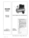
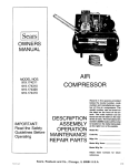
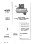
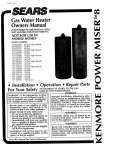
SEARS
OWNERS
MANUAL
MODEL NO.
919.176850
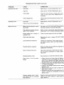
CRAFTSMAN AIR COMPRESSOR
Record in the spaces provided,
(1) The model number which can be
found on the label on the rear of the
air tank.
(2) The code number which can be
found on the foil label on the rear of
the air tank,
(3) The Manufacturers Number (ASME
Code Compressors only) is located
on the metal data plate which is
welded onto the backside of the air
tank. (This data plate is painted the
same color as the tank.)
(4) The Motor Manufacturers
name
which is located on the motor label
or specification plate.
(5) The Motor Mfg. number
- also
located on the motor label or specification plate.
Retain these numbers for future
reference,
IMPORTANT:
Read the Safety Guidelines
and All Instructions
Carefully Before Operating
ASSEMBLY
OPERATION
MAINTENANCE
REPAIR PARTS
Model No,
Code No.
Mfg. No. __
Motor Mfg, Name
Motor Mfg. No.
Sears,
81-30-14-7-B
3/89
Roebuck
and
Co., Chicago,
IL 60684
U.S.A.
TABLE OF CONTENTS
Page
WARRANTY
SAFETY
..................................................................
GUIDELINES
WARNING
CHART
SPECIFICATION
GLOSSARY
3
.......................................................
3
...........................................................
CHART
3
.....................................................
5
..................................................................
ACCESSORIES
GENERAL
FOR
USE
INFORMATION
DESCRIPTION
ASSEMBLY
WiTH
AIR COMPRESSORS
...................................................
OF OPERATION
INSTRUCTIONS
SEARS
5
.............................................
.................................................
...........
6
6
6
7
Items You Wil! Need to Assembly Your Compressor ...............................
7
Installing Handle .............................................................
7
Installing Rubber Foot Strip and Wheels .........................................
8
Installing Shut-Off Valve ......................................................
8
INSTALLATION
AND
BREAK-IN
PROCEDURES
............................
8
Location of Air Compressor ....................................................
Extension Cords .............................................................
Lubrication and Oil ...........................................................
8
8
8
Grounding Instructions ........................................................
Break-in Procedures .........................................................
9
9
OPERATING
PROCEDURES
MAINTENANCE
................................................
..............................................................
9
10
Air Filter - Inspection and Replacement .........................................
Oil - Checking and Changing ..................................................
Air Tank - Draining Water .....................................................
Check Valve - Replacement ...................................................
10
10
10
10
Safety Valve - Inspection .....................................................
Motor ......................................................................
10
10
Belt - Replacement ...........................................................
To Adjust Belt Tension ........................................................
Pulley and Flywheel - Alignment ...............................................
11
11
1!
STORAGE
.........................................................
TROUBLESHOOTING
AIR COMPRESSOR
11
GUIDE ................................................
DIAGRAM
-AIt
Models
................................
Parts List ...................................................................
AIR COMPRESSOR
PUMP
DIAGRAM
=. ...................................
Parts List ...................................................................
HOW TO ORDER
REPAIR PARTS ...........................................
11
14
17
15
17
18
FULL ONE YEAR WARRANTY
ON AIR COMPRESSORS
If this air compressor fails due to a defect in material or workmanship within one year from the date of
purchase, return it to the nearest Sears Service Center/Department throughout the United States and
Sears will repair it, free of charge.
If this air compressor is used for commercial
from the date of purchase.
or rental purposes, the warranty will apply for ninety days
This warranty gives you specific legal rights and you may have other rights that vary from state to
state.
Sears, Roebuck and Co., Sears Tower, Dept. 698/7131 CR-W, Chicago, IL 60684
SAFETY
GUIDELINES
This manual contains information that is important for you to know and understand. This information
relates to protecting your safety and preventing equipment problems. To help you recognize this
information, we use the following symbols. Please read the manual and pay special attention to
sections headed by these symbols.
URGENT
SAFETY
INFORMATION
- A
HAZARD
THAT WILL CAUSE SERIOUS
INJURY OR LOSS OF LIFE.
IMPORTANT SAFETY INFORMATION
- A
HAZARD THAT MIGHT CAUSE SERIOUS
INJURY OR LOSS OF LIFE.
NOTE
Information
equipment.
for preventing
damage
to
Information that you should pay special attention to.
WARNING
HAZARDS CAN OCCUR IF EQUIPMENT IS NOT USED PROPERLY,
PLEASE READ THE FOLLOWING CHART.
WHAT TO
LOOK FOR
WHAT COULD HAPPEN
HOW TO PREVENT
IT
Compressed
Air
Compressed air can propel dust, dirt or loose
particles it comes in contact with.
Never point any nozzle or sprayer toward a person
or any part of the body.
Always wear safety goggles or glasses when using
the air compressor.
Always turn the air compressor off and release air
pressure from hose before attaching or removing
accessories.
Too much air pressure applied to air tools or
accessories
can cause damage or risk of
bursting.
Check the manufacturer's maximum pressure
ing for air tools, accessories, or the item you
pressurize. An air regulator must be added for
with those items having a maximum pressure
ing tess than 125 psL
ratwil!
use
rat-
m_
.....
WHAT TO
LOOK FOR
WHAT COULD HAPPEN
HOW TO PREVENT IT
Unsuita6te
S_vents"
The solvents 1,1,1- Trichloroethane and Methylene Chloride can chemically react with aiuminum used in paint spray guns, paint pumps, etc.,
and cause an explosion. These solvents can
also react with galvanized components and
cause corrosion and weakening of parts. This
does not affect your air compressor- but it may
affect the equipment being used.
If the material you intend to spray contains the solvents listed at left (read the label or data sheet), do
not use accessories that contain aluminum or galvanized parts. You must either change the material
you intend to spray, or use only stainless steel
spray equipment.
Electricity
Your air compressor is powered by electricity.
Like any other electrically powered device, if it is
not used properly it can cause electrical shock.
Always unplug the air compressor prior to maintenance or repair.
Never use the air compressor outdoors when it is
raining.
Always plug the cord into an electrical outlet with
the specified
voltage
and adequate
fuse
protection.
Moving
Parts
Toxic Vapors
Air Tank
This compressor cycles automatically when the
switch is in the "On-Auto" position. If you
attempt repair or maintenance while the compressor is operating, or with the switch in the
"On-Auto" position, you can expose yourself to
moving parts. These moving parts can cause
serious injury or damage, if they come into contact with you or your clothing.
Always unplug the unit and release air pressure
from the tank and any accessories before doing
repair or maintenance.
It is normal for compressed air to contain toxic or
irritating vapors. Such vapors are harmful if
inhaled.
Never directly inhale the compressed air produced
by this unit.
Certain materials you are spraying (like paint,
weed killer, sand or insecticide) can be harmful
if you inhale them.
Read labels and safety data for all materials you
spray. Follow al! safety precautions.
Modifications to the air compressor can cause
the air tank to rupture or explode.
Never operate the compressor with the belt guard
removed.
Use a mask or respirator if there is a chance of
inhaling toxic sprayed materials. Masks and
respirators have limits and will only provide protection against some kinds and limited amounts of
toxic material. Read mask and respirator instructions carefully. Consult with a safety expert or
industrial hygienist if you are not sure about the use
of a certain mask or respirator.
Do not adjust, remove or tamper with the safety
valve or pressure switch. If safety valve or pressure
switch replacement is necessary, a part with the
same pressure rating must be used.
For Service Replacement use only the motor, pulley and belt designed as standard service replacement parts indicated in the parts list. Use of
improper parts could cause overloading of your
unit and electrical supply.
Do not substitute a gas engine for the motor.., this
compressor was not designed to be powered by a
gasoline engine.
Never replace the compressor pump with a different model.
Never increase the compressor pump speed.
Do not fix mount or permanently attach the compressor feet. This outfit is intended for portable use
(with wheels) only.
Changing the air tank will cause it to weaken.
The tank can rupture or explode.
Never drill into, weld, or in any way modify the air
tank. Do not repair a leaking tank, it must be
replaced.
Never replace the air tank with a different model or
a larger tank.
WHAT TO
LOOK FOR
WHAT COULD HAPPEN
HOW TO PREVENT IT
Hot Parts
The compressor head and tubes get hot when
the air compressor is running. If you touch them,
you can be seriously burned.
Never touch the air compressor head or tubes during or immediately after operation.
Flammable
Vapors
It is normal for the motor and pressure switch to
spark when the compressor starts or stops. A
spark can ignite flammable
vapors from
Operate the compressor in well ventilated areas
that are free of gasoline, flammable paint or solvent
vapors.
gasoline, solvents or some paints and cause a
fire or explosion.
If spraying a flammable material - provide ample
ventilation. Never spray in a closed area. There
must be a flow of fresh air at all times.
SPECIFICATION
CHART
Model No.
Horsepower
Displacement CFM
Bore
Stroke
Voltage-Single Phase
Minimum Branch Circuit Requirement
*Fuse Type
919.176850
5
15.2
27/8"
2"
240
1_ amp
Fusetron
Type "T"
20 ASME
100
125
11.3
9.3
8.0
Yes
Air Tank Capacity - Gallons
Approximate Cut-in Pressure
Approximate Cut-out Pressure
SCFM _ 40 psig
SCFM (_ 90 psig
SCFM #! 125 psig
U,L. Listed
*A circuit breaker is preferred. Use only a fuse or circuit breaker that is the same rating as the branch circuit the air
compressor is operated on. If the air compressor is connected to a circuit protected by fuses, use dual element time delay
fuses (Buss Fusetron Type "T" only).
This air compressor
amp circuit if:
4. Circuit is equipped with 15 amp circuit
breaker or 15 amp Fuestron Type "T" time
delay fuse.
can be operated on a 15
If any of the above conditions cannot be met, or if operation of the compressor repeatedly causes interruption of
the power it may be necessary to operate it from a 20
amp circuit. It is not necessary to change the cordset if
this change is made.
1. Voltage supply to circuit is normal.
2. Circuit is not used to supply any other
electrical needs (lights, appliances, etc.)
3. Extension cords comply with specifications in owners manual.
GLOSSARY
CFM." Cubic feet per minute.
SCFM: Standard cubic feet per minute; a unit of measure of air delivery.
PSIG."Pounds per square inch gauge; a unit of measure
of pressure.
ASME: American Society of Mechanical Engineers;
made, tested, inspected and registered to meet the
standards of the ASME.
U.L. Listed: Underwriter
Laboratories;
Samples of
compressor outfits, taken from production, were sub =
mitted to U.L. and found to comply with their requirements for design and performance,
Cut-In Pressure: While the motor is off, air tank pressure drops as you continue to use your accessory. When
the tank pressure drops to a certain low level the motor
will re-start automatically. The low pressure at which the
motor automatically re-starts is called "cut-in pressure."
Cut-Out Pressure: When you turn on your air compressor and it begins to run, air pressure in the air tank begins
to build. It builds to a certain high pressure before the
motor automatically shuts off - protecting your air tank
from pressure higher than its capacity. The high pres.
sure at which the motor shuts off is caUed "cut-ou
pressure."
ACCESSORIES
FOR USE WITH SEARS AIR COMPRESSORS
Tile following accessories are available through the current general sales catalog or at full-line Sears stores.
*SPRAY GUNS
.BLOW GUNS
-AIR CAULKING GUNS
,AIR POWERED WASHER GUNS
-SAND BLASTERS
,AIR BRUSHES
-AIR LINE FILTERS
*TIRE AIR CHUCKS
-PAINT TANKS
*AIR TANKS
*INFLATOR KITS
.QUICK CONNECTOR SETS
(various sizes)
oVISCOSIMETER
*AIR PRESSURE REGULATORS
*OIL FOG LUBRICATORS
*AIR TOOLS:
Sanders
Drills
Impact wrenches
Hammers
,AIR HOSE:
1/4", 5/16" OR 3/8" LD.
in various lengths.
GENERAL INFORMATION
_'ouhave purchased an air compressor unit consisting of
a 2 cylinder, single stage air compressor pump, an air
:ank, air hose, wheels, handle, air chuck and associated
:ontrols and instruments.
for removal of moisture and oil vapor in compressed air
when a paint spray gun is used.
An in-line lubricator is usually required for air tools to
prolong toot life.
Your air compressor can be used for operating paint
spray guns, air tools, caulking guns, grease guns, air
3rushes, sandblasters, power washers, inflating tires
and plastic toys, spraying weed killers, insecticides, etc.
Separate air transformers which combine the functions
of air regulation and/or moisture and dirt removal should
be used where applicable.
Fhis model is not equipped with a pressure regulator. An
_ir pressure regulator is usually necessary for most of
:hese applications. An Air Line Filter is usually required
These accessories can be purchased from most Sears
stores or through the Sears General catalog or Power
Tool catalog.
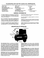
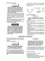
DESCRIPTION
OF OPERATION
V/eVE
\
Air Compressor Pump: To compress air, the pistons
move up and down in the cylinders. On the downstroke,
air is drawn in through the air intake filter and then
through the air intake valves. The exhaust valve remains
closed. On the upstroke of the piston, air is compressed.
The intake valves close and compressed air is forced
out through the exhaust valve, through the outlet tube,
through the check valve and into the air tank. Working air
is not available until the compressor has raised air tank
pressure above that required at the air outlet.
Check Valve: When the air compressor is operating, the
check valve is "open", allowing compressed air to enter
the air tank. When the air compressor reaches "cut-out"
pressure, the check valve "c!oses", allowing air pressure
to remain inside the air tank.
Pressure Switch: The pressure switch automatically
starts the motor when the air tank pressure drops below
the factory set "cut-in" pressure. It stops the motor when
the air tank pressure reaches the factory set "cut-out"
pressure.
Pressure Release Valve: The pressure release valve
located on the side of the pressure switch, is designed to
automatically release compressed air from the compressor head and the outlet tube when the air compressor reaches "cut-out" pressure or is shut off. If the air is
not released, the motor will try to start, but wil be unable
to. The pressure release valve allows the motor to restart freely. When the motor stops running, air will be
heard escaping from the valve for a few seconds. No air
should be heard leaking from the valve when the motor is
running.
SafetyValve:ifthe pressure switch does not shut off the
air compressor at or near itscut-out pressure setting, the
safety valve will protect against high pressure by "popping out" at its factory-set pressure (slightly higher than
the pressure switch cut-out setting).
ASSEMBLY
items You Will Need To Assemble
Compressor
Shut-Off Valve: Turn the knob counterclockwise
open the valve and clockwise to close,
to
INSTRUCTIONS
Your
• 16 oz, compressor oil, Sears 9-16426 or SAE 20-20W
SF or SG motor oil
• pipe thread sealant
. an adjustable wrench for attaching the shut-off valve
- a 9/16" socket or open-end wrench for attaching the
wheels and hose adapter
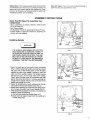
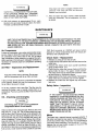
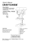
Installing
Handle
BENT
TABS
WARNING
SADDLE
I
THE WHEELS AND HANDLE DO NOT PROVIDE ADEQUATE CLEARANCE, STABILITY
OR SUPPORT FOR PULLING THE UNIT UP
AND DOWN STAIRS OR STEPS. THE UNIT
MUST BE LIFTED OR PUSHED UP A RAMP.
DO NOT LIFT THE UNIT BY THE MANIFOLD
ASSEMBLY. THE UNIT CAN BE DAMAGED.
1. Insert the open end of the handle under the saddle
(Fig. 1). Before attaching handle, you may have to pull
the open ends of the handle apart so they fit tightly
against the side of the saddle. Looking in from the
open end of the saddle, position the handle towards
the two bent tabs, on the inside wails of the saddle.
Slowly push the open ends of the handle onto both
tabs at the same time (Fig. 2). Continue pushing the
handle into the saddle until the holes on the side of the
saddle and handle are in line.
2. Guide the straight end of each retaining ctip through
the saddle hole and both handle holes (Fig. 3).
3. Rotate each retaining clip clockwise and press down
until it snaps into place over the pull handle (Fig. 4).
4. If the handle has excessive movement, it is improperly
installed. Check the following:
A. Are both tabs inside the handle (Step #1)?
B. Does each clip pass through both the saddle and
handle (Step #2)?
FIG. 1
SENT TAB
(ONE ON
EACH SIDE)
OPEN END
OF HANDLE
FIG. 2
HANDLE
INSERTED
ON
TABS
FiG. 3
7
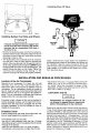
Installing
Shut-off
Valve
ADAPTER
FIG. 4
installing
Rubber
Foot Strip and Wheels
L.........
]
It may be necessary to brace or support one
end of the outfit when attaching the wheels
because the air compressor
will have a
tendency to tip.
1. Remove the protective paper strip from the adhesivebacked rubber foot strip. Attach the rubber foot strip to
the bottom of the air tank leg. Press firmly into place.
(See page 14 key no. 39.)
_-.The leg bracket on the underside of the air compressor tank has 2 holes on each side for mounting the
wheels. Place one shoulder bolt through the hole in a
wheel. Next, push the bolt through the LOWER hole of
the leg bracket and screw on one hex locking nut. The
special locking nut does not turn freely. Tighten the
nut firmly until it contacts the leg. See pg. 14. The
outfit will set level if the wheels are properly installed.
INSTALLATION
Location
SWIVEL
CONNECTION
Apply a small amount of pipe sealant (not supplied) to
the tapered pipe threads on the adapter and tighten into
the manifold. Install the swivel connection end of the
shut-off valve to the straight threaded end of the adapter
(pipe sealant is not required) and tighten this connection. See photo above.
AND BREAK-IN
of the Air Compressor
Operate the air compressor in a clean, dry and well
ventilated area. The air filter must be kept clear of
obstructions which could reduce air delivery of the air
compressor. The air compressor should be located at
least 12" away from walls or other obstructions that could
interfere with the flow of air through the fan bladed flywheel. The air compressor crankcase and head are
3esigned with fins to provide proper cooling.
If humidity is high, a Sears air filter can be installed to
remove excessive moisture, and oil vapor from the air.
Closely follow the instructions packaged with the filter
Forproper installation, it must be installed as close as
oossible to the accessory.
Extension
SHUT-OFF
VALVE
Cords
Foavoid voltage drop and power loss to the motor, use
._xtra air hose instead of an extension cord.
f an extension cord must be used:
use only a 3-wire extension cord that has a 3-blade
grounding plug and a 3-slot receptacle that will accept
the plug on the product.
make sure the extension cord is in good condition.
the extension cord should be no longer than 50 feet.
PROCEDURES
- the minimum wire size is 12 gauge (AWG) Sears #983606, 12 g. x 50' tg. ext. cord at your local Sears Service Center. (Wire size increases as gauge number
decreases. 10 AWG and 8 AWG may also be used. DO
NOT USE 14 AWG or 16 AWG.)
Lubrication
and Oil
Compressors
are shipped without oil. Do
not attempt to operate this air compressor
without first adding oil to the crankcase,
Place unit on a level surface. Remove oil fill plug (Key no.
77, pg. 15) and slowly add a special compressor oil such
as Sears 9-16426 or SAE 20-20W SF or SG motor oil
until it is even with the top of the oil fill hole. (It must not be
allowed to be lower than %"- 6 threads down - from the
top, at any time.) When filling the crankcase, the oil flows
very slowly. If the oil is added too quickly, it will overflow
and appear to be full. Crankcase oil capacity is !6 fluid
ounces. Under winter-type conditions use SAE 10W oil.
Multi-viscosity oil, 10W30, will leave carbon deposits on
critical components
reducing performance and compressor life. Replace oil fill plug.
Grounding
instructions
WARNING
If these grounding instructions
are not completely
understood, or if you are not sure your compressor is
properly grounded, have the installation checked by a
qualified electrician.
1
I
II
IMPROPER GROUNDING CAN RESULT IN
ELECTRICAL SHOCK. IN THE EVENT OF A
SHORT CIRCUIT, GROUNDING REDUCES
THE RISK OF SHOCK BY PROVIDING AN
ESCAPE WIRE FOR THE ELECTRIC CURRENT. THIS AIR COMPRESSOR MUST BE
PROPERLY GROUNDED.
1. The air compressor is equipped with a cord having a
grounding wire and an appropriate grounding plug.
The plug must be used with an outlet that has been
installed and grounded in accordance with all local
codes and ordinances. The outlet must have the
same configuration as the plug. DO NOT USE AN
ADAPTER.
2. Do not modify the plug that has been provided, If it
does not fit the available outlet, the correct outlet
should be installed by a qualified electrician.
3. Inspect the plug and cord before each use. Do not use
if there are signs of damage.
ELECTRICAL
SHOCK HAZARD.
WHEN
REPAIRING OR REPLACING THE CORD OR
PLUG, KEEP THE GROUNDING WIRE SEPARATE FROM THE CURRENT-CARRYING
WIRES. NEVER CONNECT THE GROUNDING WIRE TO A FLAT BLADE PLUG TERMINAL.
(THE GROUNDING
WIRE HAS
INSULATION
WITH AN OUTER SURFACE
THAT IS GREEN - WITH OR WITHOUT YELLOW STRIPES.)
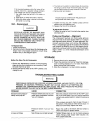
OPERATING
1. Before attaching an air hose or accessory, make sure
the pressure switch lever is in the "OFF" position.
Close the shut-off
valve by turning the knob
clockwise.
2. Attach hose and accessory.
WARNING
IIII
TOO MUCH AIR PRESSURE
CAUSES A
HAZARDOUS RISK OF BURSTING. CAREFULLY FOLLOW STEPS 3 THROUGH
11
EACH TIME THE COMPRESSOR IS USED.
3. Check the manufactur's maximum pressure rating for
air tools and accessories. The regulator outlet pressure must never exceed the maximum pressure rating. On this model, a regulator must be installed
before using accessories rated at less than 125
psig.
240 VOLT, 20 AMP PLUG
PLUG
OUTLET
OUTLET
GROUND
Break-in
GROUNDINGJ
PiN
Procedures
Serious damage may result if the following
break-in
instructions
are not closely
followed.
This procedure is required only once, before the air compressor is put into service.
!. Set the pressure switch lever to the "OFF" position.
2. Plug the power cord into the correct branch circuit
receptacle,
3. Open the shut-off valve, turn it counterclockwise to
open, opening it fully, to prevent air pressure build-up
in the tank,
4. Move the pressure switch lever to "ON/AUTO". ThE
compressor will start.
5. Run the compressor for 30 minutes. Make sure the
shut-off valve is open and there is no tank pressur(
build-up,
6. After 30 minutes, close the shut-off valve by turnin(.
the knob clockwise. The air receiver will fill to cut-ou
pressure and the motor will stop. The compressor i:
now ready for use.
PROCEDURES
Compressed air from the outfit may contain
water condensation
and oil mist, Do not
spray unfiltered air at an item that could be
damaged.
Some air operated
tools or
devices may require filtered air. Read the
instructions for the air tool or device.
4. Turn the pressure switch lever to the "ON-AUTO" posi
tion and allow tank pressure to build. The motor wil
stop when tank pressure reaches cut-out pressure.
5. Open the shut-off valve. Your outfit is ready for use.
When You Are Finished:
6. Set the pressure switch lever to "OFR"
7, Close the shut-off valve.
8. Remove the air tool or accessory.
9. Open the shut-off valve and allow the air to slow
bleed from the tank. Close the shut-off valve wh_
tank pressure is approximately 20 psi.
NOTE
If the drain cock valve is plugged, release all air
pressure. The valve can then be removed,
cleaned, and reinstalled.
WATER WILL CONDENSE IN THE AIR TANK.
tF NOT DRAINED, WATER WILL CORRODE
AND WEAKEN THE AIR TANK; CAUSING A
RISK OF AIR TANK RUPTURE.
11. After the water has been drained, close the drain
cock (turn clockwise). The air compressor can now
be stored.
10. With tank pressure at approximately 20 psi., open
the drain cock and allow moisture to drain. Turn drain
T-handle counterclockwise to open.
MAINTENANCE
WARNING
I
UNIT CYCLES AUTOMATICALLY WHEN POWER tS ON. WHEN DOING MAINTENANCE, YOU MAY
BE EXPOSED TO VOLTAGE SOURCES, COMPRESSED AIR OR MOVING PARTS. PERSONAL
INJURIES CAN OCCUR. BEFORE PERFORMING MAINTENANCE OR REPAIR UNPLUG THE UNIT
AND BLEED OFF ALL AIR TANK PRESSURE. NEVER OPERATE THE UNIT WITH THE BELT
GUARD REMOVED.
Air Compressor
A clean air compressor runs cooler and provides longer
service. Clean or blow off fins and any other parts of the
air compressor that collect dust or dirt. Do not place
rags, containers or other material on or against the ventilation openings in the belt guard. Adequate ventilation is
necessary to maintain proper air compressor operating
temperature,
Air Filter - Inspection
and Replacement
NOTE
Keep the air filter clean at all times. Do not operate the compressor with the air filter removed.
A dirty air filter will not allow the compressor to operate
at full capacity. Before you use the compressor, check
the air filter to be sure it is clean.
10W. Multi-viscosity
oil (10W30) will leave carbon
deposits on critical components which will reduce performance and compressor life.
Check
Safety
If it is dirty, replace it with a new filter. The filter may be
removed by using a pair of needle nosed pliers or a
screwdriver. Pull or pry out the old filter. Push in the new
air filter.
Oil - Checking
and Changing
Overfilling
with oil will cause premature
compressor failure. Do not overfill=
Check oil level in the crankcase daily. Remove the oil fill
plug (Key no. 77, pg. 15). The oil level should be even
with the top of the fill hole and must not be allowed to be
lower than 3/8" from the top (6 threads) at any time. It is
recommended that the oil be changed after every 100
hours of operation. To drain the oil, remove the oil drain
plug and collect the oil in a suitable container. Be sure to
replace the plug securely before adding new oil Use a
special compressor oil such as Sears 9-16426 or SAE
20-20W SF or SG motor oil (Crankcase oil capacity is 16
fluid ounces.) Under extreme winter conditions use SAE
b
Valve - Replacement
1. Release air pressure from the air tank.
2. Loosen the top and bottom tube nuts and remove the
outlet tube,
3. Unscrew the check valve (turn counter-clockwise)
using socket wrench. (7/8").
4. Check that the valve disc moves freely and that the
spring holds the disc in the upper, closed position.
The check valve may be cleaned with a solvent- such
as paint thinner or carburetor cleaner.
5. Apply sealant to the check valve threads. Reinstall the
check valve (turn clockwise). Do not over tighten.
6. Replace the outlet tube and tighten top and bottom
tube nuts.
Valve - Inspection
WARNING
J
IF THE SAFETY VALVE DOES NOT WORK
PROPERLY OVER-PRESSURIZATION
MAY
OCCUR, CAUSING AIR TANK RUPTURE OR
EXPLOSION.
OCCASIONALLY
PULL THE
RING ON THE SAFETY VALVE TO MAKE
SURE THAT THE SAFETY VALVE OPERATES FREELY. IF THE VALVE IS STUCK OR
DOES NOT OPERATE SMOOTHLY, IT MUST
BE REPLACED WITH A VALVE HAVING THE
SAME PRESSURE RATING.
Motor
The motor has a manual thermal overload protector, tf
the motor overheats for any reason, the overload protector wilt shut off the motor. The motor must be allowed to
cool down before restarting. Turn the unit off. To restart,
depress the red reset button located on the end of the
motor and turn the unit on.
NOTE
3. The motor is mounted on a special base. By loosening
the wing nut at the motor hold down plate, the motor
can be tilted to allow for easy removal of the belt.
4. Remove belt and replace.
If the overload protector shuts the motor off frequently, check for a possible voltage problem.
Low voltage can also be suspected when:
!. the motor does not get up to fult power or
speed;
2. fuses blow out when the motor is started.
3. lights dim when motor is started, and remain
dim while it is running,
NOTE
The belt must be centered over the grooves on
the flywheel and motor pulley.
5. Tighten the wing nut until it makes contact with the
washer plus one additional turn.
6. Replace the front of the beltguard.
Belt - Replacement
t
WARNING
To Adjust Belt Tension:
1. Tighten the wing nut until it contacts the washer, plus
one more turn.
SERIOUS
INJURY
OR DAMAGE
MAY
OCCUR IF PARTS OFTHE BODY OR LOOSE
ITEMS GET CAUGHT IN MOVING PARTS.
NEVER OPERATE THE OUTFIT WITH THE
BELT GUARD REMOVED. THE BELT GUARD
SHOULD BE REMOVED ONLY WHEN THE
COMPRESSOR IS UNPLUGGED.
Pulley and Flywheel
To Replace Belt:
1. Unplug compressor.
2. Remove the front of the belt guard by disengaging the
snaps, Insert a flat bladed screwdriver at each snap
location and pry the beltguard apart.
- Alignment
The compressor flywheel and motor pulley grooves
must be in-line (in the same plane) within 1/32"to assure
belt alignment within grooves. To check alignment, disconnect electrical power and remove the beltguard.
Place a straightedge against the outside of the flywheel
and measure the distance from it to the nearest groove.
Alignment is achieved when the other end of the straightedge is within 1/32"of the measured dimension at the
pulley groves.
STORAGE
Before You Store The Air Compressor:
1. Review the "Maintenance" section on the preceding
pages and perform maintenance as necessary. Drain
th,e water from the air tank.
2. Set the OFF/AUTO switch to the "OFF" position, and
unplug the unit,
3. Remove the air tool or accessory.
4. Protect the electrical cord and air hose from damage
(such as being stepped on or run over). Wind them
loosely around the outfit handle,
5. Store the compressor in a clean and dry location.
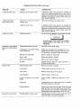
TROUBLESHOOTING
GUIDE
WARNING
PERFORMING
REPAIRS MAY EXPOSE VOLTAGE SOURCES,
MOVING PARTS, OR COMPRESSED AIR SOURCES. PERSONAL INJURY MAY OCCUR. PRIOR TO ATTEMPTING
ANY
REPAIRS THE COMPRESSOR
MUST BE UNPLUGGED
AND TANK PRESSURE RELIEVED.
NEVER OPERATE THE UNIT WITH THE BELT GUARD REMOVED.
PROBLEM
CAUSE
CORRECTION
Excessive tank pressure safety valve pops off.
Pressure switch does not shut off
motor when compressor reaches
"cut-out" pressure.
Move the pressure switch lever to the "OFF" position. If the outfit doesn't shut off, and the electrical
contacts are welded together, replace the pressure
switch.
If the contacts are good, check to see if the pin ir
the bottom of the pressure relief valve is stuck. If i
does not move freely, replace the valve=
Pressure
high.
Air leaks at fittings
switch
"cut-out"
too
Return the outfit to the Sears Service Center t(
check and adjust or replace switch.
Tube fittings are not tight enough.
Tighten fittings where air can be heard escaping
Check fittings under soapy water solution. DC
NOT OVER-TIGHTEN.
TROUBLESHOOTING
GUIDE (continued)
ROBLEM
CAUSE
CORRECTION
ir leaks at check valve
Defective or dirty check valve.
A defective check valve results in a constant air
leak at the pressure release valve when there is
pressure in the tank and the compressor is shut off.
Remove and clean or replace check valve. DO
NOT OVER-TIGHTEN.
ir leaks at pressure
,vitch release valve
Defective
pressure
release valve.
Remove and replace the release valve.
,ir leaks in air tank
switch
Defective check valve.
A defective check valve results in a constant air
leak at the pressure release valve when there is
pressure in the tank and the compressor is shut off.
Remove and clean or replace check valve, DO
NOT OVER-TIGHTEN.
Defective air tank.
Air tank must be replaced. Do not repair the leak.
,
WARNING
DO NOT DRILL INTO, WELD, OR OTHERWISE MODIFY AIR TANK OR IT WILL
WEAKEN.
;ompressor is not supplying
nough air to operate accescries.
:nocking noise
Prolonged excessive use of air.
Decrease amount of air usage.
Compressor is not large enough
for air requirement.
Check the accessory air requirement. If it is
higher than the CFM or pressure supplied by your
air compressor, you need a larger compressor.
Restricted air intake filter.
Clean or replace air intake filter.
Hole in hose.
Check and replace if required.
Check Valve restricted.
Remove and clean or replace.
Air leaks.
Tighten Fittings. (See Air Leaks Sections
Troubleshooting Guide.)
Defective check valve.
Remove and clean or replace,
Loose pulley.
Tighten pulley set screw to 70-80 in. tbs.
Low oil level.
Maintain prescribed oil level, Add oil.
Loose flywheel.
Tighten screw to 15-20 ft. Ibs.
Loose compressor
screws.
kit leaks from safety valve
mounting
Check screws.
ft. Ibs.
Tighten
of
as required to 15-20
Loose belt.
Tighten wing nut on motor mount until it contacts
the washer, plus one more turn.
Carbon build up.
Remove the head and valve plate. Clean the valve
plate and the top of the piston. (Be sure carbon
does not fall into the cylinder.) Reassemble using
new gaskets and torque screws, 25 to 30 ft. Ibs,
Possible defect in safety valve
Operate safety valve manually by pulling on ring. If
valve still leaks, it should be replaced.
TROUBLESHOOTING
GUIDE (continued)
PROBLEM
CAUSE
CORRECTION
Excessive belt wear
Loose belt.
Adjust tension. See Belt Replacement,
pg. 11.
Tight belt.
Adjust tension. See Belt Replacement,
pg. 11.
Loose pulley.
Check for worn keyway or pulley bore. Also
check for bent motor shaft. Replace parts if
necessary.
Pulley misalignment.
Motor pulley and flywheel grooves must be in line
within 1/32".
Loose belt.
Adjust tension. See Belt Replacement,
There is no oil in the compressor.
Add oil.
Motor overload protection switch
has tripped,
Let motor coot off and reset switch by pressing th_
red button located on the end of the motor.
Tank pressure exceeds pressure
switch "cut-in" pressure.
Motor will start automatically when tank pressur_
drops below "cut-in" pressure of pressure switch.
Wrong gauge wire or length of
extension cord.
Check for proper gauge wire and cord length.
Check valve stuck open.
Remove and clean or replace. DO NOT OVER
TIGHTEN.
Loose electrical connections.
Unplug the compressor. Check wiring connection inside pressure switch and motor terminal
box area.
Possible defective capacitor.
Return to Sears Service Center for inspection
replacement if necessary,
Paint on internal motor parts.
Have motor checked at a Sears Service Center.
Do not operate compressor in or near a paint
spray area.
Possible defective motor.
Have checked at a local Sears Service Center.
Fuse blown,
tripped.
t. Check fuse box for blown fuse and replace i
necessary. Re-set circuit breaker. Do not use
fuse or circuit breaker with higher rating thal
that specified for your particular branch circuit
2. Check for proper fuse; only Buss Fusetron Typ{
"T" fuses are acceptable.
3. Check for low voltage conditions and/or prope
extension cord.
4. Remove check valve and clean or replace if it i
stuck open or closed.
5. Disconnect the other electrical appliances fror
circuit or operate the compressor on its ow
branch circuit.
Squealing sound
Motor will not run
circuit
breaker
Pressure release valve on pressure switch has not unloaded
head pressure.
pg. 11.
o
Bleed the line by pushing the lever on the pressur
switch to the "OFF" position; if valve does n(
open, replace it.
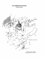
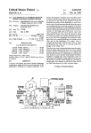
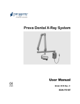
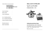
AIR COMPRESSOR
DIAGRAM
(view from back)
17
25
27
52
54
28A
\
53
49
\
51
36A
50
48A
35
48
46
37 (Model No, shown here)
40
(See pg. B, Step 2 for proper
wheel placement and assembly)
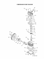
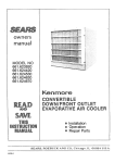
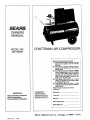
COMPRESSOR
PUMP DIAGRAM
58
61
60
87
! 86
73
74
75
80
76
... (oil fill plug)
(oil
drainplug)
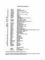
PART LIST (continued)
51
52
53
54
55
56
57
58
59
V' 60
• 61
SS-391
C-BT-223
SSF-986
LA-1951
SSF-6627
CAC-293
SSF-955
SS-8553
SSP-9401
CAC-291
265-25
•
SSF-9821
CAC-294
265-196
•
62
63
64
65
l/ 66
•lk 67
4" 68
"1"69
70
71
72
73
74
75
76
77
78
79
v" 50
81
82
l/ 83
84
85
86
87
V' 88
=/ 89
90
91
92
CAC-259
CAC-54-1
CAC-56
CAC-58
CAC-57
CAC-55
265-19
CAC-207
265-410
SSF-927
CAC-51
265-41
SSP-1413
SSF-925
265-3
265-16
CAC-373
265-23
265-13
265-9
265-2
SSN-1014-ZN
STD523107
265-111
265-6
CAC-4284
SS-3222-CD
CAC-366
9-16269
9-16163
SI-30-14-7-B
Set screw
Poiy-V-Be|t, 39" long
Self-tapping screw (2 used)
Label
Stud 3/8" x 16 both ends (2 used)
Head
Screw, 315-16 x %1/2" (4 used)
Adapter
Adapter
Head gasket
Intake flapper valve - square corners t_
(2 used on head)
Screw #5-40 × 1/4"(8 used)
Restrictor plate (2 used)
Exhaust flapper valve - beveled corners
(2 used on valve plate)
FValve plate
Valve plate gasket
Compression ring (4 used)
Oil ring (4 used)
Oil ring expander (2 used)
Piston (2 used)
Piston pin (2 used)
Piston pin plug (4 used)
Connecting rod assembly (2 used) includes two SSF-927 screws.
Screw, 1/4-20 x 1-1/8" (4 used)
Crankcase and cylinder
Needle bearing
Pipe plug (2 used)
Screw, 1/4-20 x 7/8" (12 used)
Base
Base gasket
Crankshaft
Needle bearing
End plate gasket
End Plate
Flywheel
Belleville washer
Cap screw
Seal
Vent filter
Shut-off valve
Pipe plug
Manifold
NOT ILLUSTRATED
Air chuck
Air hose assembly (1/4" LD. x 15')
Owner's Manual
•_p Key Noo87, 68 and 69, only available
in Ring Kit KK-4313
vr Key No, 6, 50, 66, 80, 83, 88 and 89, available as individual parts and part of Gasket Kit KK-43!2-2,
• Key No, 61, 62 and 64, only available in Valve Kit KK-4275o
PARTS LIST
KEY
NO.
1
2
3
4
5
6
7
8
9
10
11
12
13
14
15
16
17
18
19
20
21
22
23
24
25
26
27
28
28A
2930
31
32
33
34
35
36
36A
37
38
38A
39
40
41
42
43
44
45
46
47
48
48A
49
50
PART NUMBER
CAC-322
CAC-323
SSF-8113-ZN
CAC-327
CAC-4003-1
9-16279
265-18
SSF-935
LA-1779
STD575051_
STD575050q
CAC-317
TIA-4150
C-GA-345
STD575026
STD575025
CAC-387
CAC-1012
SSW-7385
H-2099
CAC-1011
CAC-1013
SSN-56-ZN
SSN-1619-ZN
SUDL-415-1
SSW-7367
LA-1531-1
CAC-4221-1
KK-4315
CAC-4215-1
SS-1287
CAC-437
SSF-928
STD-541631 LA-1848-1
CAC-320
LA-1814
LA-1978
LA-1952-1
CAC-1059
CAC-399
SUDL-6=I
CAC-66
CAC-4293
STD541437
SS-2707
Not Available
TA-4072
LA-1811-1
CAC-287
MO-6436
LA-1946-1
STD580104
C=PU-2861
DESCRIPTION
Belt guard, outside
Belt guard, inside
Lock nut
Bracket
Compressor pump assembly
includes Key No. 55 through 89 inclusive.
Intake filter - package of 2 (t used)
Filter retainer
Screw, #8-32 x 3/8" (2 used)
Hot Surface Label (2 used)
Ferrule (2 used for 1/2" O.D. Tube)
Nut (2 used for 1/2" O.D. Tube)
Outlet tube
Safety valve
Pressure gauge
Ferrule (2 used for 1/4" O.D. Tube)
Nut (2 used for 1/4" O.D. Tube)
Pressure release tube
Hold down plate
Strain Relief
Adapter
Eiastomer spring
Hold down screw
Flat Washer
Lock Washer
Cord assembly
Strain relief
Label
Pressure switch
Pressure release valve and mounting nut (Included with #28)
Motor cord assembly
Nipple
Check valve
Screw 5/16"-18 x 7/8" (4 used)
Wing nut
Warning label
Handle
Periodic maintenance labet
Drain tank label
Specification label
Retaining Clip (2 used)
Plastic Sleeve
Rubber foot strip
Shoulder bolt (2 used)
8" wheel (2 used)
Lock nut (2 used)
Drain cock
Code number label
Air tank, 20 gallon ASME
Sears Craftsman label
Pivot pin
Motor, 5 HP
HP label
Motor shaft key (3/16" x 3/16" x 11/4"_
Motor pulley