1
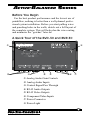
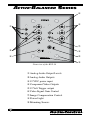
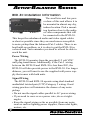
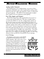
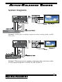
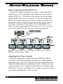
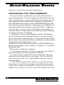
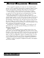
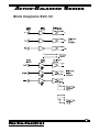
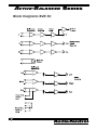
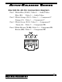
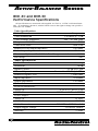
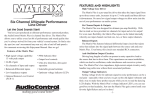
Active-Balanced Series
Installation and
Operation Manual
BVD-30™
Active Balanced Driver
for Component Video/Analog Audio and Control Signals
BVR-30™
Active Balanced Receiver
Wall Mountable Component Video/Analog Audio Receiver
T
hank you for choosing an AudioControl Active-Balanced
product for your video and audio distribution needs. You are
installing some of the most innovative custom installation products
available. These units will allow you to transmit and receive hi-definition component video, three channels of analog audio plus four
control signals over dual Category 5 wires using AudioControl’s high
quality active circuitry. Please note that these products are primarily designed for installation by professional audio video companies.
Therefore if any part of this manual is not clear … STOP WHAT
YOU ARE DOING! Contact your nearest audio video installation
company or call us and we will refer you to one. Plasma monitors,
projectors and some DVD players are too expensive to damage so
don’t attempt anything you are unfamiliar with.
Now sit back, grab yourself a cold beverage and take a moment to
read through this manual before you charge off into the installation.
Remember, once you or your Custon Installation specialist cuts a
hole in the wall in the wall, you are committed.
®
For Those Who Think Perfection Possible®
Active-Balanced Series
Active Balanced Video and Audio Products
Here are some of the cool features of your new Active
Balanced Sender and Receiver units using dual Cat-5 wires:
• Extends Highest-Quality Component Video, analog
audio and control signals up to 1000 feet (305 meters)
• Uses dual standard, inexpensive, twisted-pair
Cat-5 cables
• Utilizes AudioControl’ s Active Balanced Technology
for maximum audio and video performance with minimal electrical interference
• Pass through inputs and outputs for extending control
signals such as IR, serial commands or low voltage
power
• High Video Bandwidth - Compatible with all 480, 720,
and 1080 Formats
• Audiophile quality analog audio performance
• Video signal sensing 12 volt output trigger
• Standard EIA-568 RJ-45 Cat-5 connection jacks
• Adjustable level controls, image compensation and
gain circuits
• Five Year Warranty and built in the USA
(not in some far away country)
®
Active-Balanced Series
Before You Begin
For the best product performance and the lowest use of
painkillers, nothing is better than a well-planned professional system installation. Before you start pulling wires
and punching holes in the walls, sketch out a full layout of
the complete system. This will help plan the wire routing
and minimize the “gotchas” later on.
A Quick Tour of the BVD-30 and BVR-30
①
②
⑧
③
④
⑤
⑥
⑦
① Analog Audio Gain Controls
② Analog Audio Inputs
③ Control Signal Pass Through
④ RJ-45 Audio Outputs
⑤ RJ-45 Video Outputs
⑥ Component Video Inputs
⑦ Power Connector
⑧ Power Light
®
Active-Balanced Series
⑥
④
①
⑦
②
⑧
③
⑤
Front view of the BVR-30
⑨
① Analog Audio Output Levels
② Analog Audio Outputs
③ 12 VDC power input
④ Component Video Outputs
⑤ 12 Volt Trigger output
⑥ Video Signal Gain Control
⑦ Image Compensation Control
⑧ Power Light
⑨ Mounting Screws
®
Active-Balanced Series
③
②
①
④
① RJ-45 video inputs/
outputs
② RJ-45 audio inputs/
outputs
③ Control signal pass
through
④ Auxilliary audio/pass
through selector
Rear view of the BVR-30
②
④
Side view of the BVR-30
®
Active-Balanced Series
BVD-30 Installation Information
The small size and low power draw of this unit allows it to
be mounted in almost any dry,
indoor location. Pick a mounting location close to the audio
or video components that will
be connected to the BVD-30.
This keeps the unbalanced audio and video signal cables
as short as possible since they are much more susceptible
to noise pickup than the balanced Cat-5 cables. There is no
heat build-up problem, so it is okay to put the BVD-30 in
a closed area. Just remember you need to at least be able to
reach the unit.
Power Wiring
The BVD-30 operates from the provided 15 volt VDC
wall plug transformer. Additionally, if the Cat-5 wiring
between the BVD-30 and BVR-30 is less than 200’, the
BVD-30 will also provide power to the BVR-30. For longer
distance, you will want to use the supplied wall power supply that comes with both units.
Signal Wiring
The BVD-30 and BVR-30 operate using dual standard
unshielded twisted-pair (UTP) Category 5 wiring. Good
wiring practices will minimize the chance of any noise
pickup.
• Do not run the signal cables parallel to AC power wiring.
• If you need to cross over a power wire, do so at rightangles.
• Keep the signal wiring as far as possible from any noise
sources such as lighting power supplies, fluorescent lights,
motors, etc.
®
Active-Balanced Series
Selecting The Pass-Through and Analog
Audio Connections
The BVD-30 and BVR-30 can be configured in 2 different ways for optimum use of the CAT-5 wiring connecting
them:
Configuration 1: Three analog audio signals plus one
pair of pass-through connections for control signals. Channel 1 Pass Thru input is not active.
Configuration 2: Two analog audio signals plus two pair
of pass-through connections for control signals. The Auxiliary Analog Audio input is not active.
You can select which configuration will work the best
for your system by changing internal jumpers on both the
BVD-30 and the BVR-30.
Jumper Settings on BVD-30
and BVR-30
Audio Channels
Pass Through Connections
BVD-30 Undercover Jumper
®
Config 1
“Audio”
Config 2
“Pass Thru”
3 pairs
2
2 pairs
4
BVR-30 Side View
Active-Balanced Series
Analog Audio Channels
Depending upon your configuration, you can use these
channels to distribute up to three high quality analog audio
signals for the left, right, and auxiliary (center or subwoofer
are good options). The BVD-30 has input gain to adjust
these signal levels for optimum sound quality.
Pass Thru Inputs and Outputs
The BVD-30 has Pass-Thru inputs that can accept 2 or
4 wires and will literally Pass-Thru these signals unprocessed to the BVR-30. See the configuration options on
the previous page to assist you in making the proper settings. You can use these Pass-Through connections to send
controls signals such as IR or serial control over the dual
Cat-5 wires. Keep in mind these connections are strictly
Pass-Through meaning they have no extra gain, buffering
or processing and are straight wire connections. Therefore
you will want to make sure that that the signals you send
and receive are capable of operating properly over the long
distances that your BVD-30 and BVR-30 are running.
Cat-5 Wiring:
The RJ-45 connections on the BVD30 and BVR-30 conform to the EIA568B standard. This is the same Cat-5
cable wiring standard that a typical
computer network utilizes. You can use
any existing 10/100 Base T network
cabling and patch bays in an installation as long as it does not run through
a router or hub. The Cat-5 wiring must
run directly from the BVD-30 to the
BVR-30.
®
Active-Balanced Series
System Diagrams
System 1: DVD player sending component video, analog audio, and IR
over cat 5
System 2: Theater processor sending component video and stereo audio
to video projector/plasma via BVD-30 and a BVR-30
®
Active-Balanced Series
BVR-30 Installation Information
The small size and low power
draw of this unit is perfect for
mounting in almost any dry,
indoor location, specifically a
double gang J-box (not provided).
Pick a mounting locations close
to the audio or video components
that will be connected to the
BVR-30. You will want to keep
the unbalanced audio and video
signal cables as short as possible
since they are much more susceptible to noise pickup than
the balanced Cat-5 cables. Just remember you need to at
least be able to reach the unit with a small screwdriver to
make any final adjustments
Video Wiring
The BVD-30 and BVR-30 have 3 high-bandwidth inputs
and outputs that are capable of extending component video
signals (3 connectors, Y, PB, PR)
Note: You cannot split or “Y-off” the video signal coming out of your BVD-30 into multiple BVR-30s as the signal
will be compromised.
Power Wiring
The BVR-30 operates with a 110 VAC to 12 volt DC wall
plug transformer (provided) that is terminated with a 5 mm
jack that will plug into the front panel. We have conveniently labeled this jack “+12VDC Input”. Please note that
the 12 volt supply transformer provided with the BVR-30
is different than the power supply that is used with other
AudioControl Active Balanced line products. Therefore, be
careful to not use the wrong power supply.
10
®
Active-Balanced Series
Remote Powering the BVR-30 via CAT-5
The BVR-30 can receive power over the CAT-5 cable
(Blue and Blue/White) from a BVD-30 or an AudioControl
Maestro M2e theater processor. If the cabling is over 200
feet, we recommend that you utilize the supplied power
supply (12 VDC/500ma) to offset any power loss from the
long CAT-5.
Grounding
The BVR-30, like all AudioControl balanced line products, is designed to offer maximum isolation from radiated
signals that can creep into the video signal path and make
your pictures look funny (we are not talking about “Ha
Ha”). By design the BVR-30 has high input impedance to
ground, which minimizes the ground loops that can appear
in a coax wired system. However, we recommend that you
always make sure the structure you are in is wired to the
National Electrical Code. The NEC standards require all
ground wires to run back to the main panel prior to termination. We now return you to your regularly scheduled
manual text…
12 Volt Output Trigger
The BVR-30 is equipped with a unique video signal sensing circuit that output a constant 12 volts (100ma) which
can be used to trigger remote mounted projectors, activate
a lift, lower a screen or trigger other automation products.
The presence of any Component (Y) or Composite video
sync signal at the RJ-45 inputs to the BVR-30 produces a
sustained +12VDC on the tip of the Video Trigger Jack.
11
®
Active-Balanced Series
Daisy Chaining Multiple BVR-30’s
The BVR-30 has the ability to receive video and audio
signals over CAT-5 and then route them on to five (maximum) BVR-30’s. This allows for wiring in a daisy chain
format rather than the star method. If you are using your
BVR-30 in this manner you need to remove the blue “termination resistor network” from the socket on the rear of
the video circuitry of the BVR-30. The last BVR-30 or
BVR-25 in the signal path MUST have the “R37” resistor
network inserted for the system to function properly.
System 3: Video signal being fed in BVD-30 and routed to multiple
BVR-30’s via daisy chain wiring
Adjusting the Video Controls
Properly setting the controls on your BVR-30 will always give you the maximum performance. Although the
unit does come “pre-set” from the factory with many of the
internal enhancements at optimum levels, we have no way
of knowing the exact length of cable that you will be using.
Therefore, we have provided a few simple controls to assist
you in the optimization of the system:
12
®
Active-Balanced Series
Gain: Simply, this control on the BVR-30 adjusts the
output level or gain on the component video connections.
Typically GAIN calibration can be made by turning on the
processor’s OSD function which will most often display
either white on a black background or vice versa. An ideal
signal for calibration is a fixed image that is 50% white and
50% black such as a “needle” or “checkerboard” pattern
that comes with many video test generators. Adjusting the
gain control will raise or lower the white levels. While this
procedure will not replace a high level ISF type video calibration, it is a good starting point.
Image Compensation: The Image Compensation control
on the BVR-30 equalizes the video signal to counteract the
effect of wire capacitance. In most cases the COMPENSATION control should be set the same as the GAIN control.
If the GAIN control is set to the “5 o’clock” position, the
COMPENSATION control should be set the same. If the
image still appears to be too soft or too edgy, further adjusting can then be done.
13
®
Active-Balanced Series
Troubleshooting
“No Picture or Sound.”
1. Confirm that Audio and Video Cat-5 wires are
conected properly.
2.Make certain the Power lights on both the BVR-30 and BVD-30 are illuminted.
3. Verify that the RJ-45 termination on both ends of the
Cat-5 is correct. We all know this is easy to get wrong. Use an RJ-45 cable tester to verify.
4. Make certain the Cat-5 cable run does NOT go through an Ethernet Router or hub. It is alright to run the signal through a passive patch bay.
5. Make certain the display or monitor is compatible with format of choice, i.e. 480Y; 1080i; etc.
“No Power Light.”
1. Confirm that you are using the proper power supplies for the BVD-30 and the BVR-30. Do the outlets have power?
2. If the units are powered via Cat-5 from either the sender or receiver, make sure the cable length is less than 200’. Use supplied power supplies if necessary.
“Horizontal bars across the screen”
1. Check the power grounding of the display device, the video processor, satellite dish, cable box, and all components in the video signal path. They should all be grounded back at the electrical panel, not locally.
2. Make sure that the CAT-5 wiring going into your BVR-30 is not running parallel with any high voltage AC systems.
14
®
Active-Balanced Series
“Video picture scrambled or colors incorrect”
1. Confirm that the “Y”, “PB”, and “PR” connections are correct.
2. Check the Cat-5 wire configurations. Use an RJ-45 cable tester.
3. Readjust cable compensation settings.
“Picture is fuzzy or edgy.”
1. Adjust the Cable Compensation control on the
BVR-30. This compensates for the increased
capacitance on longer Cat-5 cable runs and sharpens the video image. Too much compensation will cause image distortion.
2. Confirm the cable length. It is important to note that the BVR-30 was designed for cabling no longer than 1000’ for standard component video or 300’ for a High Definition signal.
“There is hum in the audio signal.”
1. Verify that the Cat-5 cable is properly terminated on both ends.
2. Make certain that the system is wired with CAT-5 twisted-pair cabling.
3. Make certain there are not any cuts, pinches, or sharp twists in the wiring, allowing a conductor to short to ground (i.e. shield, conduit, cold water pipe, plenum).
“No +12 volt trigger output”
1. Measure output with voltmeter.
2. Confirm amperage required for automation system. Install relay if necessary.
3. The video signal feeding the BVR-30 is too low or uncalibrated. Re-adjust gain and calibration controls.
“My ice maker is making a funny noise”
Frankly, we have no idea.
15
®
Active-Balanced Series
And now, a word from the legal department...
CONDITIONAL FIVE YEAR WARRANTY
Custom electronics installations are an invisible element of
many modern homes. You don’t appreciate what they do for you
unless something goes wrong. AudioControl recognizes this fact
and engineers the most bulletproof components we know how.
We stand behind that quality, with a full FIVE YEAR parts and
labor factory warranty when our components are installed by an
authorized AudioControl dealer in the United Sates. Otherwise
your warranty is one year. You will be happy to know that our
warranty returns are rigorously tracked and very few of the units
we build ever need to be repaired.
“Conditional” doesn’t mean anything ominous. The Federal
Trade Commission tells all manufacturers to use the term to indicate that certain conditions have to be met before they’ll honor
the warranty. If you meet all of these conditions, we will warrant
all materials and workmanship on your
AudioControl Active Balanced product for FIVE YEARS from
the date you bought it, and we will fix or replace it, at our option,
during that time.
Here are the conditional conditions:
1. A completed warranty card must be returned to us within 15
days after signing off on the products installation.
2. A sales receipt is required for proof of purchase showing
when and from whom the unit was bought. We’re not the only
ones who require this, so it’s a good habit to get into with any
major purchase.
3. Your AudioControl product must have originally been purchased from or installed by an authorized AudioControl professional. This warranty is transferable. You do not have to be the
original owner, but you do need a copy of the original sales slip.
16
®
Active-Balanced Series
4. You cannot let anybody (A) who isn’t: the AudioControl
factory or (B) somebody authorized in writing by AudioControl,
service your product. If anyone other than (A) or (B) messes
with your AudioControl product, that voids your warranty.
5. The warranty is also void if the serial number is altered
or removed, or if the unit has been used improperly. Now that
sounds like a big loophole, but here is all we mean by it:
Unwarranted abuse is: (A) physical damage (don’t use your
AudioControl product to play fetch with your dog or hlevel your
kitchen table, jack up your car or keep the rain off your head);
(B) improper connections (120 volts into the power jack can fry
the poor thing); (C) sadistic things. This is the best product we
know how to build, but if you mount it to the filter pump of a hot
tub, something will probably go wrong.
Assuming you conform to 1 through 5, and it really isn’t all
that hard to do, we get the option of fixing your old unit or replacing it with a new one.
Legalese Section
This is the only warranty given by AudioControl. This warranty gives you specific legal rights that vary from state to state.
Promises of how well your BVR-30 will perform are not implied
by this warranty. Other than what we have covered in this warranty, we have no obligation, express or implied. Also, we will
not be obligated for direct or indirect consequential damage to
your system caused by hooking up the AudioControl BVR-30.
Failure to send in a properly completed warranty card negates
any service claims.
17
®
Active-Balanced Series
Repair Information
In the unlikely instance that you ever need to have your
AudioControl component repaired. Please contact our factory for return instructions. Repairs are handled quickly
at our factory. You are responsible for paying the freight
charges to our factory. If your unit is under warranty, we’ll
ship it back to you the same method that you sent it into
us. Please make certain that you include a note stating the
problem with the unit (you’d be surprised how many people
forget that) along with your name, return shipping address
and a daytime telephone number.
Our Repair Address is:
AudioControl
Attn: Service Department
22410 70th Avenue West
Mountlake Terrace, WA 98043 USA
Phone 425-775-8461
18
®
Active-Balanced Series
Block Diagrams BVD-30
19
®
Active-Balanced Series
Block Diagrams BVR-30
20
®
Active-Balanced Series
EIA-568 RJ-45 Pin Connection Diagram
Pair 1
Pair 1
Pair 2
Pair 1
Pair 3
Pair 1
Pair 4
Pair 1
White-Blue (W-BL) Video 4 – : Audio/Video
Blue (BL) Video 4 + : Audio/Video
White-Orange (W-O) Video 1 + : Component Y
Orange (O) Video 1 – : Component Y
White-Green (W-G) Video 2 + : Component P
Green (G) Video 2 – : Component PB
White-Brown (W-BR) Video 3 + : Component PR
Brown (BR) Video 3 – : Component PR
21
®
Active-Balanced Series
BVD-30 and BVR-30
Performance Specifications
All specifications are measured with supplied 110 VAC to 12 VDC wall transformer
and . As technology advances, AudioControl reserves the right to change our specifications, like our weather.
Video Specifications
Video Channels
Component
Video Bandwidth
150 MHz @ -3 dB
Video formats supported
480, 720, and 1080
Component Video Connections
RCA
Video Slew Rate
1500 V/uS
Balanced Video Input Impedance
100 ohms
Video Output Impedance
75 ohms
Maximum Optimum Cat-5 Cable Run Component video
1000’
HD 1080p
300’
Audio Specifications
Audio Channels 3 analog
Headroom
10 dB
Signal to Noise
95 dB ref 1 volt
Channel Separation
Greater than 75 dB @ 1 KHz
Balanced Signal Level
3 Vrms max
Input Impedance
20 kohms
Output Impedance
150 ohms
General
Physical dimensions:
BVD-30
4” H x 5.2” W x 1.3” D
BVR-30
4.5” W x 4.6” W x 1.75” D
Power Supply:
BVD-30 15 VAC
BVR-30
12 VDC
Cable Connection
RJ-45 EIA-568B Standard
Output trigger voltage
12 volts at 100mA
Warranty
5 Years
22
®
Active-Balanced Series
©2007, AudioControl, a division of Electronic Engineering and
Manufacturing, Inc. All rights reserved. AudioControl, For Those Who
Consider Perfection Possible, Maestro M2e, BVD-30, and BVR-30 are
all trademarks of Electronic Engineering and Manufacturing, Inc. This
literature was conceived, designed, and written under the protective
canopy of the lush, green, misty rain forest on a drizzly, gray overcast
day at our home in the Pacific Northwest.
23
®
®
For Those Who Consider Perfect Possible®
22410 70th Avenue West
Mountlake Terrace, WA 98043 USA
Phone 425-775-8461 • Fax 425-778-3166
www.audiocontrol.com
P/N 913094