1
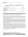
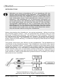
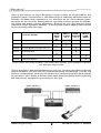
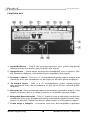
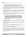
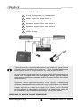
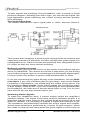
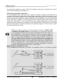
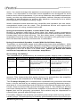
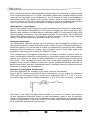
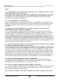
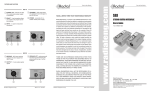
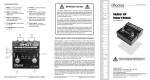
www.tonebone.com
™
Radial
Headbone VT & SS
Part # VT R800 7040 00
SS R800 7084 00
Owner’s Manual
Radial Engineering
1638 Kebet Way, Port Coquitlam BC V3C 5W9
tel: 604-942-1001 • fax: 604-942-1010
email: [email protected] • web: www.radialeng.com
Radial Engineering is a division of C • TEC (JP CableTek Electronics Ltd.)
>>> IMPORTANT SAFETY AND LIABILITY NOTICE <<<
Radial Engineering (JP Cabletek Electronics Ltd.) manufactures
products that are safe for use when connected as per the instructions in our owner’s manuals. Manuals are freely available for
download on our web sites. As it is impossible for Radial to ensure
the user is following these instructions, the user must take full
responsibility in the suitability of purchasing a Radial product for
his or her use.
For safe operation, the Headbone MUST be properly grounded, not
only to provide shielding from hum and noise, but also to prevent
any SHOCK HAZARD. The Headbone is connected to the earth
ground (AC-3rd ground pin) via its connection to Amp-1. You must
make sure that both amplifiers being connected to the Headbone
are properly grounded and equipped with a 3rd safety pin on the
AC plug. It may be unsafe to use the Headbone with vintage amplifiers equipped with a 2-prong plug or amplifiers whose 3rd pin
has been removed or lifted. For safety, always consult a qualified
technician on making proper connections to the equipment that
you wish to connect.
It is important to note that all Radial products that function using
AC or DC electrical current, are sold with a government agency
approved power supply for use around the world (i.e. UL, CSA etc.).
We insist that Radial products be used with equipment that carries
the same or similar safety government approvals. If you plan to use
equipment that has not been approved by a government-approved
electrical safety body, you are doing so at your own risk.
By purchasing this product, you clearly understand that you are taking full responsibility for the use of this product. If, after purchasing
this product from your dealer, you are not comfortable in accepting
this responsibility, we ask that you return the product within 7 days
to the dealer for refund, credit or exchange. Consult your dealer on
their policy regarding this matter.
Radial Engineering accepts no responsibility (consequential or
inconsequential) for damage or injury caused by improper connections, user error, using improperly grounded amplifiers, or injury
caused by failure of the Headbone or any component inside. The
use of the Headbone implies that the user/owner agrees to all of
the terms stated within this document, and has made the decision
to keep the Headbone under these terms, and waives his/her
rights to a liability claim against Radial Engineering (or associated
companies or directors) for any damage or injury caused while
using the Headbone. Please read the Headbone warranty for
further details.
True to the Music
RADIAL HEADBONE™ OWNER’S MANUAL
Table Of Contents
Page
Caution Statement & Legal Disclaimer ..............................Inside cover
Introduction ................................................................................1
Feature Set ................................................................................3
Quick Start .................................................................................5
Getting To Know Your Headbone ..............................................7
FAQ ...........................................................................................11
Warranty ............................................................................Back cover
Congratulations on your purchase of a Radial Headbone!
As part of the growing family of Tonebone products, the Headbone is designed to open doors to creative new sounds and provides the discerning
guitarist with greater options on stage and in the studio with a simple, yet
extremely versatile interface.
The Headbone is designed to connect two amplifier heads to one speaker
cabinet and switch between amplifiers with a footswitch. The Headbone
uses pure Class-A electronics under digital control for the hi-impedance
guitar signals and hi-power speaker signals. Add Slingshot™ remote
control and you get a true marvel whose time has come! Best of all, the
Headbone is engineered to ensure the safe operation of either tube (VT)
or transistor (SS) amps.
To take advantage of all of the wonderful features that have been incorporated into the Headbone, please take the time to read through
this manual before you use it. This will give you a broader sense of the
Headbone’s capabilities and ensure its safe and proper operation. If you
have questions that are not covered here, please visit the FAQ section
on our web site. This is where we post answers from questions that come
from users. If you have a question that is not covered there, please feel
free to send us an email at [email protected] and we will do our very
best to respond as quickly as possible.
Start your engines!
Radial Engineering is a division of JP CableTek Electronics Ltd.
Radial Headbone Owner’s Manual - Part # R800 9680 00 • V1.0 06-20-04
Specifications and appearance are subject to change without notice.
Radial Engineering
Headbone Owner’s Manual
True to the Music
INTRODUCTION
Whether you have a Headbone VT or a Headbone SS, the
setups and connections are identical. For simplicity, this
manual will discuss the Headbone VT. It is important to note
that because of the very different nature of solid-state amps
and valve-tube amps, each Headbone’s internal circuit is
different. The Headbone VT is exclusively designed for
valve-tube amps; the Headbone SS is exclusively designed
for solid-state amps. As such the SS and VT are not interchangeable. Attempting to use a solid-state amp with the
Headbone VT (or vice versa) could damage your amp and/or
the Headbone. This would void your warranty. Please consult
your dealer and make sure you fully understand the ownership disclaimer before using the Headbone.
When developing the Headbone, we asked guitarists: “What would be
the ultimate guitar setup?” Ask 10 guitarists this question and you will
likely get 10 different answers. The reason for this is simple: There are
no right answers as the possibilities are endless. So where do you start?
You need a concept. The following is a setup concept that will help get
those creative juices flowing. It combines simplicity with awesome stage
performance.
The guitar connects to the effects on the pedalboard. The pedalboard is
connected to the Headbone input. The Headbone connects to the inputs
of the two amplifier heads. The amplifer outputs are brought back to the
Headbone which, in turn, connects to the speaker cabinet. In the example
below, amp head-1 is a 100-Watt 2-channel amp with one channel set to
clean and the other set to saturated overdrive distortion. Amp head-2 is
a low power 30-Watt amp that would be driven ‘hard’ for natural output
tube overdrive. Add a good distortion pedal and all of a sudden your setup
becomes a tone monster.
Typical Headbone setup with a channel
switching head and a single channel head.
Radial Engineering
1
Headbone Owner’s Manual
True to the Music
Why is this setup so cool? Because it truly covers all of the bases: the
powerful clean sound from a 100-Watt amp is radically different than an
all-tube 30-Watt amp cranked to 10. Not just as far as loudness goes,
but also as far as tone. Being able to use that reserve power for blistering solos can make a huge difference. Best of all, you only have to carry
around a single speaker cabinet - a luxury that is best appreciated at two
in the morning after the gig!
OVERDRIVE
PEDAL
TYPE OF SOUND
Tone-1
Clean Rhythm
Tone-2
Solo Distortion
Tone-3
Crunch Rhythm (change amp ch.)
Tone-4
Saturated Solo
Tone-5
Overdrive Rhythm (change heads)
Tone-6
Saturated Rhythm
X
X
HEAD-1
CLEAN
CH. 1
HEAD-1
CRUNCH
CH. 2
HEAD-2
OVERDRIVE
X
X
X
X
X
X
Tone chart: two amp heads, one distortion pedal, one speaker cabinet,
six distinct amp tones.
This is the point: with the Headbone in your rig, you are now able to specify
which amplifier you will use for a particular song or passage. You do not
have to compromise. And you do not have to carry around two amp-stacks
to get there. Yes, finally a device that adds tonal flexibility while reducing
the amount of equipment you bring to the gig!
AMP HEAD-2
AMP HEAD-1
Radial Engineering
2
Headbone Owner’s Manual
True to the Music
FEATURE SET
1. Input Buffered – This is the primary input for your guitar and pedal
effects that do not buffer (pre-amplify) the signal.
2. Input Direct – Used when driving the Headbone from a device, like
the Radial Loopbone, that buffers (pre-amplifies) the signal.
3. To Amp-1 Input – This is a ¼” hi-impedance guitar signal output that
connects from the Headbone to the input of the first guitar amplifier.
4. To Amp-2 Input – This is a ¼” hi-impedance guitar signal output
that connects from the Headbone to the input of the second guitar
amplifier.
5. Ground Lift – This recessed switch connects the ground to Amp-2. This
switch is factory set in a ‘lifted’ position to eliminate ground loops.
6. Slingshot Remote Input – This ¼” input is used to remotely control the
Headbone from your pedalboard using a standard contact closure footswitch or another Tonebone device that features a Slingshot output.
7. From Amp-1 Output – Connects from the first amplifier’s speaker
Radial Engineering
3
Headbone Owner’s Manual
True to the Music
output jack back to the Headbone. This is a speaker level signal, so
use a good quality speaker cable for best power transfer.
8. From Amp-2 Output – Connects from the second amplifier’s speaker
output jack back to the Headbone.
9. To Speaker Cabinet – Connects the Headbone to your speaker
cabinet.
10. Power Supply Connection – The Headbone comes with its own
15VDC power supply in a choice of 100V, 110V, 220V and 240V
models.
11. Footswitch – Used to toggle the Headbone between Amp-1 and
Amp-2
12. LED Indicators – Indicates which amplifier head is active.
QUICK START
Radial Engineering
4
Headbone Owner’s Manual
True to the Music
Before making any connections, ensure that your amplifiers are turned off, the Headbone power supply is disconnected, and volume controls are set to zero.
1. Begin by connecting your guitar to the Headbone’s ¼” Buffered Input.
This will allow you to test the system more effectively during the initial
setup. For unbuffered (Direct) input use, please go to the section that
discusses this on page 7.
2. From the Headbone, connect the To Amp-1 Input jack to your first
amp’s guitar input. This circuit connects the guitar to your first amplifier. Always use good quality shielded cable to ensure low noise and
best performance.
3. From the Headbone, connect the To Amp-2 Input jack to your second
amp’s guitar input. This circuit connects the guitar to your second
amplifier when the footswitch is toggled.
You are now ready to connect the speaker jacks.
At this time, you should check to make sure both
amplifiers have their impedance set to match the
speaker cabinet impedance. If you are unsure about
this, consult a qualified technician. Always use good
quality speaker cables to ensure the best possible
power transfer.
4. From your first amp’s speaker output, connect to the Headbone’s
From Amp-1 Output jack. This brings the signal from amp-1 back to
the Headbone.
5. From your second amp’s speaker output, connect to the Headbone’s
From Amp-2 Output jack. This brings the signal from amp-2 back to
the Headbone.
6. From the Headbone’s To Speaker Cabinet jack, connect to your
speaker cabinet. You are now ready to start system tests.
7. Connect the Headbone’s power supply. The Headbone will turn on and
you will see one of the LEDs illuminate.
8. You can now turn on your guitar amplifiers. It is a good practice to
test equipment setups at a low volume to reduce any possibility for
system damage should there be an improper connection. Turn up
the volume slowly while listening for excessive noise. Depress the
footswitch to make sure both amps are working. If all is well, you are
ready to crank it up!
Radial Engineering
5
Headbone Owner’s Manual
True to the Music
QUICK START CONNECTIONS
1
Signal from guitar or pedalboard.
2 Guitar signal to amp head-1.
3
Guitar signal to amp head-2.
4
Speaker signal from amp head-1.
5
Speaker signal from amp head-2.
6
Speaker signal to speaker cabinet.
7 Power supply
Throughout this manual, references are made to “guitar level
signals” and “speaker level signals”. The Headbone passes
both types and it is important to use the proper cables.
A guitar level signal requires a good quality shielded cable to
work well. You will find that using high quality guitar cables
with proper shielding will help reduce system noise and radio
interference.
Speaker level signals require good quality unshielded
speaker cables. We recommend using a minimum of 14 AWG
cables for speaker cable runs under 8 feet. Larger gauge
cables should be used for longer runs. Never use shielded
guitar cables for speaker connections. A Headbone cable kit
is available from Radial Engineering. Ask your dealer.
GETTING TO KNOW YOUR HEADBONE
Radial Engineering
6
Headbone Owner’s Manual
True to the Music
To best explain the workings of the Headbone, take a minute to study
the block diagram. Reading from left to right, you can see the inputs, the
high-impedance guitar switching, the control circuitry and the speaker
level switching.
The Input Signal Path
The Radial Headbone’s input signal path is 100% discreet Class-A.
This means that it employs a whole bunch of parts such as resistors and
capacitors instead of a transistor to buffer (amplify) the guitar signal to a
manageable level. Class-A circuits are preferred over integrated circuits
(IC chips) as they are more natural sounding.
Buffered and Direct Inputs
The Headbone gives you the choice of two inputs: one buffered and one
direct or unbuffered. The reason we do this is that when you are driving
a pre-buffered signal, there is no advantage to buffering the signal again.
In some cases, two buffers in series could add distortion or noise.
If you are connecting the guitar directly to the Headbone, use the Buffered Input. If you use a buffering device (pre-amp), such as the Radial
Loopbone or Switchbone, you would plug the output of the device into
the unbuffered Direct Input. Some effect pedals use a buffering stage
in their design, some do not. If you are connecting an effect pedal before
the Headbone, the best way to decide which input to use is to let your
ears choose the one that sounds best to you.
Switching Guitar Signals
To make the Headbone work, it cannot simply switch the amplifier’s
speaker outputs. The inputs to the amp must be switched as well. It is
important that the input going to the unused head be turned off so that
while on standby, it is not trying to amplify a signal with nowhere to go.
The Headbone simultaneously switches the amp’s inputs and outputs.
Actual head switching is performed by a series of opto-couplers, which
are made to ramp-up and ramp-down the guitar signal in such a way as
Radial Engineering
7
Headbone Owner’s Manual
True to the Music
to avoid any clicks or pops. The PIC digital controller controls this action
(see block diagram on page 7).
Switching Speaker Signals
To accomplish this task, the PIC sends a status change command to a
series of internal relays that connect the speaker to the active amp, and
connect the load resistor to the standby amp. Always use good quality,
large conductor speaker cable between the Headbone, your amps and
your speaker cabinet, as this will reduce signal loss and improve the
transient response. Your Headbone has been designed to work with
amps whose maximum output is 100-watts RMS. The power is limited
by the relay that is used to switch the speaker signals. To be safe, never
exceed this power limit.
Effects such as echo or loop-playing devices, MUST BE
CONNECTED BEFORE the Headbone so that their residual
or sustaining sound can be disconnected from the input of
the amplifiers. This means that you cannot use any type of
echo device that prolongs a signal on the amplifier’s effects
loop or after the Headbone in your signal chain. Failure to
do so could cause the echo to continue to play through the
standby amp which, in turn, would continue to amplify the
signal without a load. This could cause the amp or the Headbone to malfunction. The Headbone’s internal resistor load
is only designed to support the standby amplifiers residual
output. The Headbone is NOT a load box.
Matching the Speaker Load
The Headbone itself has no effect on amplifier load or speaker imped-
Radial Engineering
8
Headbone Owner’s Manual
True to the Music
ance. You must manage the speaker connections for the best impedance
match. It is important to note that most amplifiers are designed to work
best at their rated impedance. If your amp features selectable impedance
loads, use the one that matches your speaker cabinet. Always consult the
amplifier’s specifications to ensure the speaker connections are within
the amplifier’s accepted working range.
While matched loads between the amplifier and speaker are the ideal,
unmatched loads can be used. The guidelines below will explain the
ramifications of using unmatched loads.
Using Unmatched Speaker Loads With Tube Amps
Driving a speaker load that is lower than the amps output impedance
(8-Ohm amp with 4-Ohm speaker) tends to drive the tubes harder, which
means they will not last as long. On the other hand, a higher speaker
impedance load (4-Ohm amp with 8-Ohm speaker) will generally sound
less full and less punchy, but tube life is extended.
Using Unmatched Speaker Loads With Solid State Amps
Transistor or solid-state amps work differently than tube amplifiers. With
solid-state amps, lowering the speaker impedance load generally makes
the amp sound louder with little change in tone. Most solid-state amps are
designed to see an 8-Ohm or 4-Ohm load. Never go below the rated
minimum impedance for transistor amplifiers.
Grounding for Safety!
The Headbone is powered by an external power supply with a floating
Amp type Rated impedance
Tube amp
8-Ohm
Solid-state
amp
8-Ohm
Higher speaker impedance
Connecting a 16-Ohm cabinet will make amps sound
less punchy & warm. You get
longer tube life.
Lower speaker impedance
Connecting a 4-Ohm cabinet
will make amps sound more
punchy and warm. You get
shorter tube life.
Connecting a 16-Ohm
Connecting a 4-Ohm cabinet
cabinet will reduce the power will increase the volume.
and lower the volume.
Check amp specification for
minimum load.
ground. This means that the guitar derives it’s ground thru the amplifier
connected to the Headbone’s To Amp-1 Input jack.
The To Amp-2 Input jack is transformer-isolated from ground to eliminate
hum or buzz caused by so-called ground loops passing between amp-1
and amp-2. A recessed ground-lift switch is provided to bypass the transformer and reconnect the ground through amp-2. The switch is factory
set in the lifted position Should the amplifier connected to the To Amp-1
Input jack not be properly grounded, this switch may be depressed to
connect the ground path through amp-2.
For safety, always use properly grounded guitar amps with 3-prong electrical AC plugs. The third prong is a safety ground that is there to protect you
Radial Engineering
9
Headbone Owner’s Manual
True to the Music
from electrical shock. Most amplifiers have been subjected to safety tests
from authorities like UL or CSA. Amplifiers that have passed these tests
are safe to use with your Headbone. If you intend to use the Headbone
with amps that only have 2-prong AC plugs, such as old vintage amps,
you are doing so at your own risk. Please consult a qualified technician
if you are not sure how to establish a safety ground connection.
Safe Mode™ Operation
One of the really smart features in the Headbone is a function called SafeMode. Should the Headbone’s DC power supply be disconnected, the
system will ‘default’ to Safe Mode, whereby AMP-1’s input and output will
automatically connect to the speaker cabinet. This simple, yet extremely
important safety feature, will ensure that the active guitar amp always
“sees” a load and that the standby amp is muted.
Slingshot Remote
The Slingshot feature allows you to position the Headbone adjacent to
the guitar amplifier setup and remotely control it from a distant footswitch.
With Slingshot you can avoid a mess of spaghetti by keeping the cables
between the Headbone, amps, and speaker short. This also improves
amplifier efficiency and reduces system noise.
The Headbone’s Slingshot Remote is a simple contact closure that allows a standard ‘latching’ footswitch to remotely toggle the Headbone’s
status from amp-1 to amp-2. Most standard ¼” mono-style footswitches
will work. The Headbone may also be used with Slingshot equipped
pedals such as the Radial Loopbone. Other pedal-switching devices or
MIDI controllers that are equipped with a contact closure output will also
be able to toggle the Headbone.
Remote Footswitch Schematic
Use this drawing for making your own remote footswitch.
Use a SPST push-on/push-off type footswitch. If you wish, an optional
LED can be included in the circuit. Any standard size ( T-1 or T-1 3/4 )
red LED with forward voltage between 1.6 & 2.2 volts (current = 20ma)
will work. The LED will light when AMP-2 is active. Connect the switch
to the Slingshot Remote input on the Headbone with a two conductor
cable. Connecting a remote footswitch to the Headbone will disable the
onboard footswitch. If you are unsure of these requirements, please refer
to a qualified electronic technician.
Radial Engineering
10
Headbone Owner’s Manual
True to the Music
FAQ
Q: I heard that tube amps must always see a speaker load or else
they will blow up. Is this true?
A: This is true. To deal with this, the Headbone is equipped to manage
two loads: the speaker for the active amp and a load resistor for the
standby amp. The Headbone transitions between these two loads
when the footswitch is toggled.
Q: Is the Headbone a load-box?
A: No. A load-box is designed to absorb an amplifiers full output and
pass a reduced amount of power to the speaker. The Headbone uses
a much smaller load resistor to provide an idle load for the standby
amplifier.
Q: Why does the Headbone use opto-couplers and relays to
switch the guitar and amp signals?
A: To switch active signals a circuit designer must choose between
voltage controlled amplifiers (VCA’s), opto-couplers, relays, or converting the signal to digital and then back to the analogue domain. The
type of guitarist that uses a Radial product is generally a purist and is
very concerned about retaining the natural tone of his instrument. VCA
and digital circuits are not acceptable as they change the tone of the
instrument. Tonebone products use opto-couplers on the hi-impedance
circuits to eliminate all switching noise and relays on the speaker level
signals where high voltage is present.
Q: I have heard that using an echo with a head switcher can cause
a problem with the amps. Is this true?
A: It depends on where the delay is positioned in the signal chain. If the
delay is placed before the Headbone, there is no problem. If the delay
device is placed after the Headbone, or in an amplifier’s effects loop,
you can have a problem because the echo may continue to generate
a signal and send it through the “stand-by” amp with no speaker load
connected. It is generally not good to run an amp this way as the output transformer can heat up and ultimately short out. Thus, always put
delay and looping devices before the Headbone in the signal chain.
Q: Can I use the Headbone like an A/B box?
A: It certainly could be done, but you may encounter ground loop
problems as the Headbone is not set up for this function. The Radial
Switchbone would definitely be a better choice.
Q: Can I use the Headbone with a MIDI switcher?
A: Yes. Most MIDI switchers are equipped with a contact closure output
jack. This would be connected to the Headbone’s Slingshot input to
remotely control amp switching.
Q: If I do not want to use the Slingshot remote, how far from the
Radial Engineering
11
Headbone Owner’s Manual
True to the Music
amps and speaker can I be?
A: As a general rule, we do not recommend running cables any more
than 20 feet as you are subjecting the signal to increased resistance. If
you are intent on doing so, use good quality cables. For speaker connections use large gauge (12AWG) speaker cables. For guitar signals
use low capacitance shielded cables.
Q: How do I know if my footswitch will be Slingshot compatible?
A: If your external footswitch employs a basic latching type switch with
a ¼” or ¼” TRS connector it will, in all likelihood, be compatible. If it
employs some type of multi-pin connector or telephone style jack, it may
not. Consult your dealer or manufacturer for advice on how you can make
an adaptor that will allow you to enjoy the benefits of the Headbone’s
Slingshot.
Q: Can I use another power supply other than the 15VDC that comes
with the Headbone?
A: No. Never use another power supply unit other than the one included
with your Headbone. Because of the Headbone’s Class-A circuit, a more
powerful 15VDC supply is required. If you need a replacement power
supply, contact your Tonebone dealer.
Q: If I have a 300-Watt amp, can I modify the Headbone?
A: Yes. In fact we have included a provision in the design to allow a
350-Watt relay to be factory installed in the Headbone. Simply contact
your Tonebone dealer for details on how you can order this special
high power version.
Q: I have two amp heads; one tube head and one solid state. Do I
use the VT or the SS?
A: Unfortunately the world of tubes cannot collide with the world of
transistors due to the way that the amps are designed. We are, however, working on the Headbone TS (tube & solid state) that will allow
you to do this. Until then, you would have to use a product like the
Tonebone Switchbone and carry two speaker cabinets.
Radial Engineering
12
Headbone Owner’s Manual
RADIAL LIMITED ONE YEAR WARRANTY
Radial Engineering - a division of JP CableTek Electronics Ltd. (“Radial”)
warrants this product to be free from defects in material and workmanship to
the original owner and will remedy any such defects free of charge according
to the terms of this warranty. Radial will repair or replace at its option any
defective component(s) of this product, excluding the finish, wear and tear
on components under normal use, and the tube and footswitch (which are
warranted for 90 days), for a period of one (1) year from the original date of
purchase. In the event that a particular product is no longer available, Radial reserves the right to replace the product with a similar product of equal
or greater value. To make a request or claim under this limited warranty,
the product must be returned prepaid in the original shipping container (or
equivalent) to Radial or to an authorized Radial repair centre and you must
assume the risk of loss or damage. A copy of the original invoice showing
date of purchase and the dealer name must accompany any request for work
to be performed under this limited warranty. This limited warranty shall not
apply if the product has been damaged due to abuse, misuse, misapplication, accident or as a result of service or modification by any other than an
authorized Radial repair centre.
THERE ARE NO EXPRESSED WARRANTIES OTHER THAN THOSE
ON THE FACE HEREOF AND DESCRIBED ABOVE. NO WARRANTIES,
WHETHER EXPRESSED OR IMPLIED, INCLUDING BUT NOT LIMITED TO,
ANY IMPLIED WARRANTIES OR MERCHANTABILITY OR FITNESS FOR
A PARTICULAR PURPOSE SHALL EXTEND BEYOND THE RESPECTIVE
WARRANTY PERIOD DESCRIBED ABOVE OF ONE YEAR.
RADIAL SHALL NOT BE RESPONSIBLE OR LIABLE FOR ANY SPECIAL OR
INCIDENTAL OR CONSEQUENTIAL DAMAGES OF LOSS ARISING FROM
THE USE OF THIS PRODUCT. THIS WARRANTY GIVES YOU SPECIFIC
LEGAL RIGHTS, AND YOU MAY ALSO HAVE OTHER RIGHTS, WHICH MAY
VARY FROM STATE/PROVINCE TO STATE/PROVINCE.
Radial Engineering
1638 Kebet Way, Port Coquitlam, BC V3C 5W9
tel: 604-942-1001 • fax: 604-942-1010
email: [email protected]
web:
www.tonebone.com
Radial Engineering is a division of JP CableTek Electronics Ltd.
Radial Headbone Owner’s Manual - Part # R800 9680 00 • V1.0 0620-04
Specifications and appearance are subject to change without notice.