1
,,,,,
,,,
,,,
--,,,,,
,,,,
®
Caution:
Read and follow
all Safety Rules
and _nstructions
Before Operating
This Equipment
o
o
o
o
o
AssembUy
Operation
Customer Responsibilities
Service and Adjustment
Repair Parts
=,.,,,
SEARS,
,=,,,,,,,.,,,
,,,,,,
,,
ROEBUCK
,,,
,,
AND CO., HOFFMAN
,,.,,
,,,,,,,,,
ESTATES, IL 60179
,,,
,,
[A
THESE INSTRUCTIONS
SAFETYRUL S
ARE FOR YOUR PROTECTION.
PLEASE READ THEM CAREFULLY.
IMPORTANT
7HIS CUTTING MACHINE
FOLLOWING
SAFETY
IS CAPABLE
INSTRUCTIONS
OF AMPUTATING
HANDS AND FEET AND THROWING
COULD RESULT IN SERIOUS
L
GENERAL OPERATION:
o
•
Know controls and how to stop qulckty.
Read, understand, and follow all instructions in the manual and
on the machine before starting,
Only show
responsible
adults, who are familiar with
instructions, to operate the machine.
Wear safety glasses or eye shields when assembling or
operating the machine.
Do not operate machine when barefooted.
Always wear
substantial footwear, preferably steel-toed shoes.
Do not wear loose fitting clothing that could get caught In
moving parts.
Clear the area of objects such es rocks, toys, wire, etc., which
could be picked up and thrown by the blade(s).
Be sure the area Is clear of other people before mowing. Stop
machine if anyone enters the area_
Never carry passengers°
Do not mow in reverse unless absolutely necessary, Always
look down and behind before and while backing.
Be aware of the mower discharge direction and do not point it at
anyone. Do not operate the mower without either the entire
grass catcher or the guard in place
Slow down before turning_
Never leave a running machine unattended Atways turn off
blades, set parking brake, stop engine, and remove keys before
dismounting,
Turn off blade(s) when not mowing.
Stop engine before removing grass catcher or unclogging
chute.
Mow only in daylight or good artificial light.
Do not operate the machine while under the Influence of alcohol
or drugs=
Watch for traffic when operating near or crossing roadways.
Use care when mowing around a fixed object to prevent the
blade(s) from striking IL Never deliberately run over any foreign
object.
Use extra care when loading or unloading the machine into a
trailer or truck,
Use care when pulling loads or using heavy equipment
a. Use only approved drawbar hitch points.
b. Limit loads to those that you can safely control,
c.
Do not turn sharply. Use care when backing.
d
Use counterweight(s), wheel weight or tire chains when
suggested in attachment(s) instructions.
•
e
e
o
e
•
e
e
e
•
•
•
e
•
o
•
•
•
•
IL
e
•
e
TO OBSERVE
THE
mower could suddenly turn over tf a wheel is over the edge of a
cliff or ditch, or if en edge caves in
Do not mow on wet grass. Reduced traction couFd cause
sliding.
Do not try to stabilize the machine by putting your foot c_nthe
ground_
Do not use grass catcher on steep slopes.
Tragic accidents can occur if the operator is not alert to the presence
of children. Children are often attracted to the machine and the
mowing sctlvity_ Never assume that children will remain where you
last saw them.
•
Keep children out of the mowtng area and under the watchful
care of another responsible adult,
•
Be alert and turn machine off if children enter the area.
e
Before and when backing, look behind and down for small
chlldrem
e
Never carry children. They may fall off and be seriously Iniured
or interfere with safe machine operation.
•
Never allow children to operate the machine.
o
Use extra care when approaching blind cornersp shrubs, trees,
or other objects that may obscure vision
IV
SERVICE:
•
o
e
e
e
SLOPE OPERATION:
•
e
e
•
®
•
e
Mow up and down slopes, not across.
Remove obstacles such as rocks, tree limbs, etc,
Watch for holes, ruts, or bumps,. Uneven terrain could overturn
the machine, Tall grass can hide obstacles
•
Use slow speed. Choose a low gear so that you will not have to
stop or shift while on the slope,
•
Follow the manufacturer's recommendations for wheel weights
or counterweights to improve stabgtty_
e
Use extra care with grass catchers or other attachmenls These
can change the stability of the machine.
e
Keep all movement on the slopes slow and gradual Do not
make sudden changes in speed or direction
o
Avoid starting or stopping on a slope. If tires lose traction, turn
off the blade(s) and proceed slowly straight down the slope
DO NOT
•
FAILURE
IlL CHILDREN:
Slopes are a major factor related to loss-of-control
and tip-over
accidents, which can result tn severe injury or death_ All slopes
require extra cautiot_ If you cannot back up the slope or if you feel
uneasy on it, do not mow 1L
DO
•
OBJECTS
INJURY OR DEATH.
•
•
•
•
e
Use extra care in handling gasoline and other fuels They are
flammable and vapors are explosive.
a. Use only an approved container.
b. Never remove gas cap or add fuel with the engine running=
Allow engine to cool before re-fueling Do not smoke
c. Never re-fuel the machine Indoors,
d
Never store the machine or fuel container inside where
there is an open flame, such as in a water heater.
Check fuel supply before each use allowing space for
expansion as the heat of the engine andlor sun can cause
gasoline to expand end overflow the tank.
Use extra care when harldllng battery acld_ Acid contact with
skin may cause severe burns. Eye contact may cause
blindness.
Use extra care when servicing the battery Explosive gas is
produced in the battery. Do not service the battery while
smoking or near an open spark or flame. This may cause the
battery to explode causing serious injury.
Never run a machine inside a closed area. Exhaust fumes
contain CARBON MONOXIDE, an ODORLESS and DEADLY
GAS.
Keep nuts and bolts, especially blade attachment bolts, tight
and keep equipment in good condition_
Never tamper with safety devices= Check their operation
regularly_
Do not change the engine governor settings or over speed
engine.
Reduce fire hazards. Keep machine free of grass, leaves, or
other debris build=up Clean up oil or fuel spillage_ Allow
machine to cool before storing.
Stop and inspect the equipment if you strike an object. Repair, if
necessary, before restarting_
Never make adjustments or repairs with the engine running
Grass catcher components are subject to wear, damage, end
deterioration,
which could expose moving parts or allow
objects to be thrown Frequently check components and
replace with manufacturer's
recommended
parts, when
necessary
Mower blade(s) are sharp and can cut Wrap the blade(s) or
wear gloves, and use extra caution when servicing them
Check brake operation frequently.
Adjust and service as
required.
Do net turn on slopes unless necessary, and then slowly and
gradually downhill, if possible=
Do net mow near dropooffs, ditches or embankments. The
LOOK
FORALERT!!!
THIS SYMBOL
TO POINT
OUT IMPORTANT
BECOME
YOUR SAFETY
IS INVOLVED.
2
SAFETY
PRECAUTIONS,
IT MEANS--ATTENTION!!!
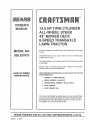
CONGRATULATIONS
on your purchase of a Sears
Craftsman Tractor It has been designed, engineered
and manufactured to give you the best possible dependability and performance
Should you experience any problem you cannot easily
remedy, please contact your nearest Sears Service
Center/Department
We have competent, well-trained
technicians and the proper tools to service or repair this
unit
Please read and retain this manual The instructions will
enabte you to assemble and maintain your tractor
_roperly Always observe the "SAFETY RULES"
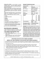
MODEL
NUMBER 536257670
PRODUCT
SPEClFnCATBONS
HORSE POWER:
15.0
GASOLINE
CAPACITY:
2 GALLONS
UNLEADED REGULAR
OIL (30 Pints)
SAE 30 - above 32°F
5W - 30" - below 32°F
SPARK PLUG :
Champion RJ 19LM
(GAP .030 in.)
VALVE
CLEARANCE:
Intake:
Exhaust:
GROUND
SPEED:
FORWARD
1st
2nd
3rd
4th
5th
6th
REVERSE:
TIRE PRESSURE:
FRONT:
REAR:
CHARGING SYSTEM:
2 4 AMPS @ 3300 RPM
8LADE BOLT TORQUE:
30-35
SERIAL
NUMBER
DATE OF
PURCHASE
THE MODEL AND SERIAL NUMBERS WILL BE
FOUND ON A PLATE UNDER THE SEAT
YOU SHOULD RECORD BOTH SERIAL NUMBER
AND DATE OF PURCHASE AND KEEP IN A SAFE
PLACE FOR FUTURE REFERENCE
MAgNTENANCE
AGREEMENT
A Sears Maintenance Agreement is available on this
product Contact your nearest Sears Store {or details
CUSTOMER
o
o
RESPONSIBILITIES
Read and observe safety rules
Fo{tow a regular schedule in maintaining, caring for and
using your unit
FOItOw the instructions
under"Customer
Responsibilities" and "Storage" sections of this manual
o
CRAFTSMAN
UMITED
122
2 51
3 21
3 79
4 76
5 92
2.7O
MPH
MPH
MPH
MPH
MPH
MPH
MPH
14 PSi
10 PSI
FT LBS
WARNING: This unit is equipped with an internal combustion engine and should not be used on or near any
unimproved forest-covered, brush+covered or grasscovered land unless the engine's exhaust system is
equipped with a spark arrester meeting applicable local
or state laws (if any) If a spark arrester is used, it should
be maintained in effective working order by the operator
In the state of California the above is required by law
(Section 4442 of the California Public Resources Code)
Other states may have similar laws Federal laws apply
on federal lands, A spark arrester for the muffler is
available through your nearest Sears Authorized Service
Center (See REPAIR PARTS section in this manual)
ELECTRRC START
TWO YEAR WARRANTY
004- 006 In
.007 - .009 in.
RIDING
ON ELECTRIC
EQUIPMENT
START
RIDING
EQUIPMENT
For two (2) years from the date of purchase, if this riding equipment is maintained, lubricated and tuned-up according to the
instructions in the owner's manual, Sears will repair or replace, any parts found to be defective in material or workmanship
This warranty does not cover:
o
Expendable items which become worn during norma! use, such as blades, spark plugs, air cleaners and belts
o
Tire replacement or repair caused by punctures from outside objects, such as nai!s, thorns, stumps, or glass
•
Repairs necessary because of operator abuse, negligence, improper storage or accident or the failure to maintain the
equipment according to the instructions contained in the operator's manual
Riding equipment used for commercial
LIMITED 90 DAY WARRANTY
or rental purposes
ON BATTERY
For 90 days from the date of purchase, if any battery included with this riding equipment proves defective in materia! or
workmanship and our testing determines the battery will not hold a charge, Sears will replace the battery at no charge
WARRANTY SERVICE IS AVAILABLE BY RETURNINGTHE RIDING EQUIPMENT TO THE NEAREST SEARS SERVICE
CENTER/DEPARTMENT iN THE UNITED STATES
This warranty gives you specific legal rights, and you may also have other rights which may vary from state to
state
SEARS, ROEBUCK AND CO , D/817WA, HOFFMAN ESTATES, IL 60179
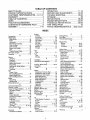
TABLE OF CONTENTS
SAFETY RULES ............................................
2
PRODUCT SPECIFICATIONS
...................... 3
CUSTOMER
RESPONSIBILITIES__3,
17-21
WARRANTY ..................................................
3
TABLE OF CONTENTS
................................
4
INDEX ...........................................................
4
TRACTOR ACCESSORIES
.......................... 5
CONTENTS OF HARDWARE
PACK ............ 6
ASSEMBLY ..............................................
7-I0
OPERATION ...........................................
11-15
SERVICE AND ADJUSTMENTS
........... 22-32
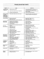
TROUBLE SHOOTING ..........................
33-34
STORAGE ...................................................
35
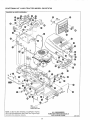
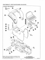
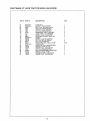
REPAIR PARTS .....................................
36-59
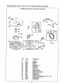
ENGINE REPAIR PARTS ...................... 60-67
TRANSAXLE
REPAIR PARTS .............. 68-69
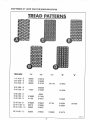
TIRE TREAD PAGE ....................................
70
PARTS ORDERING/SERVICE
..... Back Cover
iNDEX
Engine:
Air Filter ..................................................
21
Air Screen ...............................................
20
Cooling Fins ............................................
20
Oil Change ...............................................
20
Oil Level .............................................
14, 20
Oil Type .............................................
3, 20
Preparation ............................................
14
Starting ..................................................
14
Storage .....................................................
35
F
Filter:
Fuel .......................................................21
Fuel:
Type ........................................................
3, 14
Storage .............................................. 35
H
Headlights ........................................... 30
Hood RemovalllnstaUaltion ................31
L
Leveling, Mower Deck ......................
23-24
Lubrication:
Chart
17
M
Mower:
Adjustment, Front-To-Rear ............. 24
Adjustment, Side-To-Side ................23
Adjustment, Deck Height ...................
24
Blade Sharpening ................................
19
Blade Replacement .......................
18
Brake Adjustment ..............................28
Cutting Height .................................. 13
Installation ..................................... 22+23
Operation ..................................................
13
Removal ...........................................
22
Mowing Tips .........................................
15
Mulching Mowing Tips .......................... 15
Muffler ....................................................
21
Spark Arrestar
21
Mulching Plug:
Installation
19
O
Oil:
Cold Weather Conditions ...........14, 20
Engine ..............................................
20
Storage
Type .......................................... 3, 14, 20
Operation .......................................
11-15
Operating Your Mower ......................... 13
Options:
Accessories .......................................... 5
Spark Arrester ........................... 3, 2t
.........................................................
3,
..................................
4
5
3
..........................................
................................................
A
Accessories ..................................................
5
Adjustments:
Blade Brake ........................................25
Brake .....................................................28
Carburetor ..............................................
32
Mower Deck Leveling:
Front-To-Rear .....................................24
Side-To-Side .............................................
23
Mower Deck Height ..............................
24
Seat .........................................................
27
Throttle Control Cable ..........................
32
Air Screen, Engine .................................
20
Assembly .............................................
7-10
B
Battery:
Charging ............................................. 9
Cleaning ..............................................19
Installation ............................................10
Battery Acid Levels .......................9, 19
Preparation .......................................... 8
Starting wilt] Weak Battery ............ 30
Storage .............................................. 35
Terminals ........................................... 19
Belt:
Tractor Drive
Removal/Replacement
......................26
Mower Blade Drive
Removal/Replacement
.................... 26
Blade:
Sharpening .........................................19
Replacement .................................. 18
Brake Adjustment ................................ 28
C
Carburetor Adjustment ..........................32
Controls, Tractor ............................... 11
Customer Responsibilities ....... 3, 17-21
Air Screen, Engine ........................... 20
Battery .............................................. 19
Blade .......................................... 18-19
Brake Operation ................................ 18
Cooling Fins, Engine ..........................20
Engine Oil ........................................3, 20
Fuel Filter .............................................
21
Lubrication Chart ..................................
17
Schedule .......................................... 16
Spark Plugs ....................................... 21
Tire Care .....................................
9, 18, 29
Cutting Height, Mower ......................... 13
E
Electrical:
Interlocks and Relays ..................... 30
P
Parking Brake .......................................... 12
Parts Bag .............................................................
6
Product Specificatio[ls .............................. 3
R
Repair Parts:
Engine ..............................................
60-67
Tractor ..............................................
36-59
Transaxle ..............................
68-69
S
Safety Rules .........................................
2
Service and Adjustments ..............22+32
Blade Brake ..........................................
25
Brake Rod ......................................28-29
Carburetor ............................................32
Choke Control .................................... 31
Control Lever .................................
29
Fuse ...................................................... 30
Hood Removal/Installation .............. 31
Tractor Drive Belt:
Removal/Replacement
............. 26-27
Mower Blade Drive Belt:
Removal/Replacement
...................... 26
Mower Deck Adjustment:
Front-To-Rear ........................................
24
Side-To-Side ...........................................
23
Mower Deck Height ...........................24
Mower Deck Removal ................... 22
Mower Deck Installation .............22-23
Seat ....................................................
27
Steering Gear ...................................... 28
Tire Care .................................. 9, 18, 29
Throttle Control ................................. 32
Wheel Repair+ .................................... 29
Spark Plugs ............................................. 21
Specifications ...............................................
3
Starting the Engine ....................................
14
Steering Wheel ..........................................7
Stopping the Tractor ............................. 12
Storage .......................................................
35
T
Table of Contents .................................. 4
Throttle Control Cable
Adjustment ..............................................
32
Tires .............................................9, 18, 29
Tire Pressure .............................. 3, 9, 18
Transaxle:
Cooling ...........................................
19
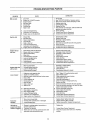
Troubleshooting Points ................. 33-34
W
Warranty ................................................ 3
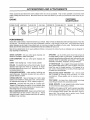
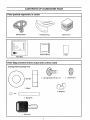
A C CESSORIES
A ND A TTA CHMEN TS
ii
These accessories and attachments were availabfe when the unit was purchased
They are also available at most Sears retail
outlets, catalog and service centers Most Sears stores can order these items for you when you provide the model number ol your
tractor
CUSTOMER
MAINTENANCE
ENGmNE
SPARK PLUG
MUFFLER
AIR FILTER
GAS CAN
ENGINE OIL
STABILIZER
BLADES
BELTS
PERFORMANCE
Sears offers a wide variety of attachments that fit your vehicle Many of these are listed below with brief explanations of how they
can help you This list was current at the time of publication; however, it may change in future years - more attachments may be
added_changesmayb_madeintheseattachrnents__rs_memayn___ngerbeavai_ab_eorfi_y_urm_de_
Contact your nearest
Sears store for the accessories and attachments that are available for your unit.
Most of these attachments do not require additional hitches or conversion kits (those that do are indicated)
easy attaching and deattaching
GRASS CATCHER - lets you collect grass clippings
leaves for a healthier, heater looking lawn
and
LAWN
leaves
and
SWEEPERS
- lets you collect grass clippings
CARTS - make hauling easy
Variety of sizes available
ROLLER - for smoother lawn surface, 36-inch wide, 18 inch
diameter water tight drum holds up to 390 Ibs of weight
Rounded edges prevent harm to turf Adjustable scraper automatically cleans drum
SPREADERS/SEEDERS
- make seeding, tertilizing and
weed killing easy
Broadcast spreaders are also useful for
granular deicers and sand
CORING AERATOR - takes small plugs out of soil to allow
moisture and nutrients to reach grass roots 36-inch swath
24 hardened steal coring tips 150 Ibs capacity weight tray
AERATOR - promotes deep root growth for a healthy lawn
Tapered 2 5" steal spikes mounted on 10-inch diameter discs
puncture holes in soil at close intervals to let moisture soak in
Steal weight tray for increased penetration
MULCH RAKFJDETHATCHER - loosens soil and flips thatch
and matted leaves to lawn surface to easy pick up Twenty
spring tine teeth
Useful to prepare bare areas !or seeding
Available for rear mounting
and are designed lot
SPRAYERS - use 12-volt DC electric motor that connects to
the tractor battery or other !2-volt source Includes booms lot
automatic spraying when pulling and hand held wand for spot
spraying Wand has adjustable spray pattern
For applying
herbicides, insecticides, fungicides, and liquid fertilizers
48" SNOW BLADE - has a rugged, heavy gauge steel blade
Spring loaded blade glides over uneven surfaces Can be adjusted from seat for straight position, or 35 degrees left or
right Locks in raised position for traveling Wheel weights and
tire chains are recommended
SINGLE-STAGE
SNOW THROWER
- has a 42-inch swath
and is capable of throwing snow accuralety
controlled are Wheel weights and tire chains
mended
in a driver
are recom-
TIRE CHAINS - are heavy duty: closely spaced extra-large
cross links give smooth ride, outstanding traction
WHEEL WEIGHTS - for rear wheels provide needed traction
for snow removal or dozing heavy materials
TILLER has 5 hp engine and 36" swath to prepare seed beds,
cultivate and compost garden residue Tiller has its own builtin lift and depth control system and does NOT require a
sleeve hitch Fits any lawn, yard, or garden tractor Simply
hook up to the tractor drawbar and go!
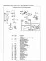
CONTENTS
OF HARDWARE
PACK
Parts packed separately in carton
Steering Wheel
Battery Acid
1 - Mulching Plug
@
Owner's
Manual
1-Video
Parts Bag
Parts Bag contents shown actual size unless noted
Steering Wheel Assembly Parts
®
2. Carriage Bolts 5/16-18 x =75
1 - Spacer
2 - Wingnuts
1 - Spring Pin
1 - Spare Key
6
2 - Lockwashers
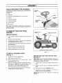
ASSEMBLY
TOOLS REQUIRED
FOR ASSEMBLY
STEERING
WHEEL
A socket wrench will make assembly easier Standard wrench
sizes are listed.
(1) Pliers
(1)
Utility knife
(1)
Screwdriver
(1)
Hammer
SPACER
SPRING PIN
(Small Phillips with a 1/4 inch shank)
STEERING
(1) Tire pressure gauge
(2)
7/16 inch wrenches
CLUTCH
LEVER
(2) 1/2 inch wrench
(1) Tape measure
When right and left hand is mentioned in this manuat, if
means when you are in the operating position (seated behind
the steering wheel)
TO REMOVE TRACTOR
CARTON
UNPACK
FIG. 1
FROM
SHIFT CONTROL
LEVER
BRAKE_;LUTCHPEDAL
CARTON
e
Open top flaps
crate.
Remove cardboard
from top of wood
e
Remove top frame from carton
e,
Carefully remove contents of parts box (see CONTENTS
OF HARDWARE PACK on page 6).
e
Cut down all four corners with a utility knife and carefully lay
down side panels+
e
Discard cardboard from alongside tractor
o
Remove cardboard from discharge chute
e
Remove plastic wrap from seat and hood
VIEW FROM RIGHT SIDE OF TRACTOR
FIG, 2
TO INSTALL
(See Fig. 1)
STEERING
WHEEL
BEFORE ROLLING
(See Fig. 2)
e
Position front wheels straight forwar&
e
Place spacer on steering shaft.
e,
Place steering
wheel
on
steering wheel down firmly
o
Align cross holes in steering wheel with holes in
steering shaft, NOTE: Use a small Phillips screwdriver with a 1/4 inch shaft to align the holes Keep
screwdriver in place as you drive the spring pin in
e
steering
shaft
Push
From the left side, ddve spring pin (found in parts bag)
through opposite side with a hammer
TRACTOR
OFF SKID
IMPORTANT: CHECK FOR AND REMOVE STAPLES IN
SKID THAT MAY PUNCTURE TIRES OF TRACTOR BEFORE
ATTEMPTING TO ROLL OFF SKID
•
Carefully cut wire ties (front and back) holding tractor to
skid
e
Release
peda!.
e
Place shift contro! lever in NEUTRAL
e
Carefully
roll tractor
backwards
off
(ASSISTANCE MAY BE REQUIRED )
IMPORTANT:
FENDER
parking
brake
DO NOT
by depressing
LIFT TRACTOR
brake-clutch
position
wood
BY HOOD
skid
OR
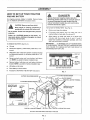
A SSEMBL Y
HOW TO SET UP YOUR TRACTOR
PREPARE
DANGER
BATTERY
Always disconnect negative (black) cable first.
Removing positive cable first can result in sparks
the wrench touches any metal surface. Be sure
battery hold-down bracket does not touch battery
terminals and cause a spark_
For shipping purposes, battery is installed Remove battery
(see TO REMOVE BATTERY instructions below)
CAUTION:
and face
shield.
Wash handsWear
or eye
clothing
immediately
if
acc!dentally in contact with battery acid
TO ACTIVATE THE BATTERY
if
(See Fig 4) -
e
Remove vent caps from battery
Do not smoke,, Fumes from charged battery acid are
explosive,
e
Fill battery with battery acid Fill each cell
reaches bottom of vent wells Do not over fill
Follow the CAUTIONS located on the battery.
Always wear gloves, clothing and goggles to protect
your hands, skin and eyes.
e
Allow battery to stand and settle for at least thirty
minutes and then check leve! of acid
If acid is
below level outlined on electrolyte package, add more
acid until correct level is reached
Lift seat.
e
Disconnect negative (-) black battery cable with a 7/16"
wrench
e
Slide battery boot away from positive (+) battery terminal
and disconnect positive (+) red battery cable with a 7/16"
wrench
•
Remove plastic wing nut from battery hold-down
rod. NOTE: Lay aside for battery installation later
•
Remove battery hold-down rod and battery hold-down
bracket, NOTE: Lay aside for battery installation later
•
Lift batteIy out of tractor
e
Place battery on level surface
e
Proceed TO ACTIVATE THE BATTERY instructions
VENTCAP
VENT
..
BATTERY
•
CUT*AWAY
HOLD-DOWN
BATTERY
CELL ACID
WELL
LEVEL
VIEW OF BA37"ERY
FIG. 4
BRACKET
NUT
NEGATIVE (-) BATTERy TERMINAL
1/4 X 3/4 INCH HEX HEAD SCREW
NEGATIVE BLACK
BATTERY CABLE
\
BATTERY
NEGATIVE (,) BLACK
BATTERY CABLE
BOOT
BA3-FERY
HOLD-DOWN
_
POSI'[IVE
(+) BATTERY
CUT-AWAY
TERMINAL
it
IMPORTANT:
TO MAXIMIZE LIFE OF YOUR BATTERY,
IT IS NECESSARY THE BATTERY BE CHARGED BEFORE
USE FAILURE TO CHARGE BATTERY CAN RESULT iN
SHORTENED BATTERY LIFE
TO REMOVE BATTERY (See Fig 3) e
until
BATTERY
VIEW FROM RIGHT-HAND
FIG_ 3
BOOT
POSITIVE
SIDE OF TRACTOR
1+} RED BATTERY
ROD
CABLE
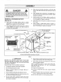
ASSEMBLY
TO LEVEL MOWER
CAUTION: Handle electrolyte with care°
It is an acid and poison. Always wear eye
shields, and protect skin when handling
acid or battery°
POISON - CAUSES SEVERE BURNS
Contains sulfuric acid.
Avoid contact with skin, eyes or clothing.
To prevent accidents, neutralize excess acid with
baking soda and rinse empty container with water,.
TREATMENT:
TO ADJUST
Mower
Always
adjust
uneven
iNTERNAL - Drink large quantities of water or milk.
Follow with milk of magnesia, beaten eggs or
vegetable oil. Call physician immBdiately..
EYES - Flush with water for 15 minutes and get
prompt medical attention°
Charge battery at a rate of six (6) amps for 1 hour
Use a 12-volt battery charger
Observe all safety
precautions required for battery charging Complete assembly section of this manual while waiting for battery to
charge,
Check battery case for leakage to make sure that no
damage has occurred in handling,
@
deck wheels may be adjusted to one of four positions
adjust both wheels to same position NOTE: Do Not
wheels to support mower deck while mowing or
cutting will result
Park tractor on a firm, level surface, such as a driveway
or garage floor
O
Set cutting height adjustment
to lowest anticipated
cutting height Deck wheels should be 1/4" off ground, if
not, adjust as follows:
0
Remove axle bolt and nut holding
each wheel
wheel mounting bracket with two 9/16" wrenches,
0
Change wheel height adjustment by relocating
wheel into desired hole of wheel mounting bracket
0
Reinstall
tightly
Check acid level after the battery is charged
If
acid has fallen below correct level, add distilled or iron
free water
o
DECK WHEELS
e
KEEP OUT OF THE REACH OF CHILDREN
Install vent caps to cover vent wells, Wash top of battery
with water to remove any acid, then wipe dry
MOWER
(See Fig. 5)
EXTERNAL - Flush with water,.
e
DECK
For best cutting results the mower deck has been leveled at the
factory and should not require any adjustment
If in the event
the deck should need to be adjusted see TO LEVEL MOWER
DECK in the SERVICE AND ADJUSTMENTS section of this
manual
to
each
bolt and nut on each side and secure nuts
MOWER
NUT
/
AXLE BOLT
\
Dispose of excess battery acid Neutralize acid for disposal by adding it to four inches of water in a five (5) gallon plastic container Stir with a wooden or plastic paddle
while adding baking soda until the addition of more soda
causes no more foaming
WHEEL MOUNTING
BRACKET
RIGHT SIDE WHEEL
SHOWN
FIG,, 5
CHECK
TIRE PRESSURE
CHECK
For shipping purposes, the tires on your tractor were over-inflated at the factory Correct tire pressure is important for best
cutting performance
e
Remove hub caps by placing two fingers in hole in each
cap and pulling them from the wheels
e
Use tire pressure gauge to check amount of air in tires
e
Reduce tire pressure to PSi shown in "PRODUCT
SPECIFICATIONS" on page 3 of this manual
•
Replace hub caps
CHECK
BELTS
•
e
POSITION
SYSTEM
After you learn how to operate your tractor, check operation of tractor brake (see BRAKE OPERATION
in
CUSTOMER
RESPONSIBILITIES
section of this
manual).
MULCHING
PLUG
Your tractor has a mulching plug kit Your tractor also has
unique 3 in t blades which are designed to side discharge,
mulch and mow without changing blades
Position on wheels and push firmly
FOR PROPER
BRAKE
e
To install the mulching plug kit see TO INSTALL MULCHING PLUG INSTRUCTIONS
in the CUSTOMER
RESPONSIBILITIES section of this manual,
o
For additional information on the mulching plug see
MULCHING MOWING HINTS in the OPERATION section
of this manual
OF ALL
See figures shown for replacing motion and mower blade
drive
belts
in SERVICE
AND ADJUSTMENTS
section of this manual Verify belts are routed correctly
IMPORTANT: if your grass needs to be cut more than 1 inch
side discharge mowing is recommended
9
ASSEMBL Y
@
DANGER
Always connect positive (red) cable firsL Connecting negative cable first can result in sparks if the
wrench touches any metal surface. Be sure battery
hold-down bracket does not touch battery terminals
and cause a spark.
REINSTALL CHARGED
(See Fig. 6)
®
e
Place threaded end of hold-down rod through loop in
bracket and secure with plastic wing nut NOTE: Tighten
with pliers if necessary
Attach positive (+) red battery cable to positive (+)
terminal on battery with a 1/4 X 3/4 inch head screw and
a 1/4 inch keps nut Tighten nut securely
BATTERY
Raise seat and place battery
back in tractor
with positive (+) terminal toward right side of tractor
NOTE: Be sure ignition key is in OFF position
@
Place battery boot over positive (+) battery terminal (see
Fig 9 inset)
@
Attach negative (-) black battery cabte to negative (-)
terminal on battery with a 1/4 X 3/4 inch hex head screw
and a 1/4 inch keps nut Tightee nut securely
Place battery hold-down bracket through slot in back of
console NOTE: Turn bracket to side, place through slot
in console and rotate upright
BATTERY
HOLD-DOWN
Place hook end of battery hold-down rod through large
hole in main frame and hook into small hole in front of
battery
X 3/4 INCH HEX HEAD SCREW
BRACKET
SLOT
(-) BATTERY
TERMINAL
1/4 X 3/4 INCH HBX HEAD SCREW
NEGATIVE (-) BLACK
BATTERY CABLE
\
BATTERy
BOOT
NEGATIVE (-) BLACK
BATIBRY
CABLE
BATTERY
HOLD-DOWN
ROD
"#
BA'I_ERY
POSITIVE
(4 _ RED
BATTERY
CABLE
POSITIVE
_LARGE
(+) BATTERY
CUT.AWAY
TERMINAL
'ERY
VIEW FROM RIGHT-HAND
BOOT
POSITIVE (+) RED BATTERY
HOLE
CABLE
SIDE OF TRACTOR
FIGo 6
,,/ CHECKLIST
BEFORE
YOU OPERATE
AND ENJOY
YOUR NEW
TRACTOR, WE WISH TO ASSURE THAT YOU RECEIVE
THE BEST PERFORMANCE AND SATISFACTION
FROM
THIS QUALITY PRODUCT
,/
Check mower and drive belts Be sure they are routed
properly around pulleys and inside all belt guides
/
Check wiring See that all connections
wires are properly clamped
are secure and
/
All assembly instructions have beer completed
WHILE LEARNING
HOW TO USE YOUR TRACTOR,
PAY EXTRA
ATTENTION
TO THE FOLLOWING
IMPOR TANT ITEMS;
_f
No remaining loose parts in carton
#V
/
Battery is properly prepared and charged
hour at 6 amps)
4'#' Fuel tank is filled with fresh, clean, regular Unleaded
gasoline
,f
Seat is adjusted comfortably and tightened securely
,,t
All tires are properly inflated (For shipping purposes, the
tires were over-inflated at the factory)
PLEASE REVIEW THE FOLLOWING CHECKLIS T:
#"
(Minimum
1
Engine oil is at proper level
,t',/ Become familiar with aI! controls-their
location
function Operate controls before starting engine
,(/"
Be sure mower deck is properly leveled side-to-side/
front-to-rear for best cutting results (Tires must be properly inflated for leveling)
10
Be sure brake system is in safe operating condition
and
OPERATION
.....,i
KNOW YOUR TRACTOR
READ THiS OWNER'S
TRACTOR
MANUAL
AND SAFETY
RULES
BEFORE
OPERATING
YOUR
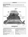
Compare illustrations (see Fig. 7) with your tractor to familiarize yourself with !ocations of various controls and adjustments
this manual for future reference,
Save
CHECK STARTING
SEQUENCE
INDICATOR
THRO'I3"LE
CONTROL
LEVER
ATTACHMENT
LEVER
AMMETER
CHOKE
CONTROL
CUTTING HEIGHT
ADJUSTMENT
PEDAL
SWITCH
BRAKE_LUTCH
PARKING BRAKE
LATCH
\
MEMORYROD
HEADLIGHT
i
SWITCH
SHIFT
CONTROL
LEVER
.=
o,.,
=.
,
FIG, 7
SEARS LAWN TRACTORS conform to the safety standards of THE AMERICAN NATIONAL STANDARDS INSTITUTE
Ignition Switch - Used to start and stop engine
Shift Control Lever - Used to select ground speed ranges
and direction of motion (forward-neutral-reverse)
Choke Control - Used to start a cold engine_
Parking Brake Latch - Used to lock brake-crutch pedal down
in park position,
Throttle Control Lever - Controls speed of engine
Headlight
Switch - Turns headlights on or off
Ammeter
running
- Shows battery is being charged when engine is
Check Starting
Sequence Indicator
wrong starting procedure was used
Brake-Clutch
Pedal
tractor and start engine
- Used
to
- Indicator
clutch
and
Cutting
of cut
Height Adjustment
Pedal - Used to change height
lights if
Memory Rod - Used with Cutting Height Adjustment Pedal to
select cutting height
brake
Attachment
Clutch Lever - Used to engage or disengage
power to mower deck blades
11
OPERA.ON
The operation of any tractor can result in foreign objects being thrown into the eyes, which can result in
severe eye damage Always wear safety glasses or eye shields while operating your tractor or performing
any adjustments or repairs
We recommend standard safety glasses, available at SEARS Retail or Catalog Stores, or a wide vision
safety mask for over your glasses
LOW
T
HEIGHT
P_DAL
1. FULLY DEPRESS
CUT HEIGHT
PEDAL
_
2, POSITIONMEMORYRODTO
DESIRED HEIGHT
3, RELEASE CUT HEIGHT
PEDAL
TO_
1, FULLY DEPRESS CUT HEIGHT
PEDAL
......................................
TO START
1 DISENGAGE ATTACHMENT CLUTCH
2 FULLYDEPRESSBEAKFJCLUTCHPEDAL
3 SHJFTTO NEUTRAL
4 SET THROTTLE TO FULL(CHOKE IF NEEDED)
S TURN IGNITION TO START
• READOPERATORS
MANUAL(S)
• KNOWLOCATION& FUNCnONOF ALLCONTROLS
KEEPGUARDSSAREWSHIELDSANDSWITCHES
INPLACEAND_ORKINGPROPERLY
. REMOVEOBJECTSTHATCANBETHROWNBY
BLADE(S)
• DO NOTMeWWHENCHILDRENOROTHERSARE
AROUND
• NEVERCARRYCHILDRENORPASSENGERS
LOOKDOWNANDBEHINDBEFOREAND
WHILEBACKING
• DO NOTMOWWHEREMOWERCANTiP ORSLiP
. IF MACHINESTOPSGOINGUP RILL.DISENGAGE
DLADEIS
) ANDBACKSOWNSLOI_/LY
• REMOVEKEYWHENLEAVINGMACHINE
• AVOIDSUDDENTURNS
• GO UPANDDOWNSLOPES,NOTACROSS
OPEP, JT_HG
INSTRUCTIONS
(READ OWNERS
MANUAL)
TO STOP
1 FULLY DEPRESS SRARFJCLUTCHPEDAL
2 D_SENGAGEATTACHMENTCLUTCH
3 SHIFTTO NEUTRAL
4. ENGAGE PARKING BRAKE
S. TURN IGNITIONTO OFF
EP,
AKE
(,_
Ig
BRAKE
CLUTCH
PEDAL
ALWAYS SET PARKING BRAKE
BEFORE LEAVINGOR ENGINE WILL
STOP
TO SET PAJ_KING BRAKE
1, FULLY DEPRESS BRAKE/CLUTCH
PEDAL
2 PUSH LEVER FOWARD AND HOLD
3, RELEASE BRAKE/CLUTCH PEDAL
TO P.EESJL_EPAJ_K_G BP.J},KE
I FULLY DEPRESS BRAKEtCLUTCH
PEDAL LEVER WILL RELEASE
..............
TO SHIFT G_auzs
1 FULLY DEPRESS BRAKE/CLUTCH PEDAL
B SHIFTTODESIREDGEAR
3 RELEASE BRAKE/CLUTCH PEDAL SLOWLY
HOW TO USE YOUR TRACTOR
•
TO SET PARKING
BRAKE
e
Depress brake.clutch
hold.
pedal fully (all the way down) and
NOTE: Under certain conditions
when unit is standing
idle with engine running, hot engine gases may cause "browning" of grass To eliminate this possibility, always stop engine
when stopping tractor on grass areas
e
Push parking brake lever forward and engage notch in
parking brake lever against main frame
TO USE CHOKE
•
To release parking brake, apply pressure to brake-clutch
pedal and spring will automatically release parking brake
lever.
Use choke control whenever you are starting a cold engine
Do not use to start a warm engine
e
STOPPING
[A
To engage choke control, pull knob out Slowly push knob
in as engine warms up to disengage
no,.,o
[
e
diately. Keep hands and feet from under
mower deck and away from discharge
chute•
Depress
e
Place shift control lever in NEUTRAL position
e
Set parking brake before leaving tractor
e
Start tractor with brake-clutch pedal depressed
control lever in NEUTRAL position
e
Move shift control lever to reverse or forward speed range
NOTE: Always corn e to a full stop before chang ins direction
of motion
e
Slowly release brake-clutch pedal to start movement
ENGINE Move throttlecontrolto SLOW position
e
Turn ignition key to OFF position and remove key Always
remove key when leaving vehicle to prevent unauthorized
AND FORWARD
The direction of motion (forward - reverse) and ground
speed ranges (1-2-3-4-5-6) are controlled by shift control
lever
brake-clutch pedal fully (all the way down)
e
Operating engine at other than FAST position reduces
battery charging rate and the engine cooling air flow.
TO MOVE BACKWARD
TRACTOR o
CONTROL
FAST throttle position is necessary for best bagging and
mowing performance
Pullthe clutch lever rearward to the DISENGAGED
position_
CONTROL
TO USE THROTTLE
MOWER BLADES e
Never use choke to stop engine
use,
12
and shift
OPERATION
TO SELECT
MOWER
CUTTING
HEIGHT
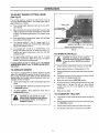
(See Fig. 8)
The cutting height is selected
by placing the memory
rod in the desired height position The cutting height range is
approximately 2 to 4 inches
PEDALLATCH
e
Press cutting height adjustment pedal all the way down
until it latches
O
Move memory rod to desired cutting height. Lowest cutting
height is toward front of tractor and highest is toward rear
of tractor, The latched pedal position is the highest cutting
position.
e
Press pedal latch to release pedal, mower deck will lower
to the desired cutting height
e
The memory positions (1 thru 5) change height of cut
approximately 3/8 inch each Total available cutting height
adjustments exceeds 2 inches
CUTTING HEIGHT
ADJUSTMENT
PEDAL
(TOp TO BOTTOM)
VIEW OF LEFT SIDE OF TRACTOR
The average lawn should be cut approximately 2-1/2"
during cool season and over 3" during hot months For
healthier and better looking lawns, mow often and after
moderate growth
e
FIG. 8
TO OPERATE
For best cutting performance, grass over 6" in height
should be mowed twice Make the first cut at the highest
position; the second to desired height.
_
If cutting blades do not cut evenly, go to "TO ADJUST
MOWER DECK HEIGHT" and "TO LEVEL MOWER DECK"
Instructions.
TO OPERATE
MOWER
Your tractor is equipped with an operator presence sensing
switch Any attempt by the operator to leave the seat with engine running and brake.clutch pedal not fully depressed with
parking brake lever locked, and/or attachment clutch lever
engaged, will shut off engine
e
Select desired height of cut with cutting height adjustment
pedal.
o
TO STARTMOWER - Slowly move attachment clutch lever
to ENGAGED position.
o
TO STOP MOWER - Move attachment
DISENGAGED position.
clutch lever to
and avoid sharp turns to prevent tipping
or loss of control.. NEVER carry passenCAUTION: On slopes, be very cautious
gers.
13
I
e
Choose slowest speed before starting up or down hills
e
Avoid stopping, starting or changing speed on hills.
e
If slowing is necessary, movethrottie controlleverto
position
e
If stopping is necessary, push brake-clutch pedal fully (all
way down) and engage parking brake
e
Move shift control lever to NEUTRAL position
®
To restart movement, release parking brake and move shift
control lever to 1st gear Be sure you have allowed
enough room for unit to roll slightly as you restart
movement
e
Make all turns slowly
TO TRANSPORT
CAUTION: Do not operate the mower
without either discharge chute deflector,
or entire grass catcher, on mowers so
equipped, in place.
ON HILLS
slower
TRACTOR
e
Fully depress cutting height ad}ustment pedal into highest
position
e
When pushing or towing your unit, be sure shift control lever
is in NEUTRAL position
e
Slowly release parking brake and brake-clutch pedal
e
Do not push or tow tractor at more than five (5) MPH
OPERATION
BEFORE
STARTING
TO START
THE ENGINE
CHECK ENGINE OIL LEVEL
When starting engine for first time or if engine has run out of
fuel, it will take extra cranking time to move fuel from tank to
engine
Read OPERATION and CUSTOMER RESPONSIBILITIES
sections of this manual before trying to start the engine
e
Check to make sure engine crankcase is full of oil Never
run engine unless crankcase is furl of oil and dipstick is
tightened securely into oil tube
e
To change engine oil, see ENGINE
CUSTOMER
RESPONSIBILITIES
manual
Your tractor has two lockout switches that connect solenoid to
brake-clutch pedal and attachment clutch lever When starting engine, brake-clutch pedal must be fully depressed and
attachment clutch lever must be in DISENGAGED position to
engage lockout switches The Check Starting Sequence indicator will light unless these conditions are met
LUBRICATION in
section
of this
Your tractor is equipped with an operator presence sensing
switch The engine will stop if operator is not firmly seated in
operator's seat when attachment clutch lever is engaged
Leaning forward or to one side on the seat may cause the
engine to stop
ADD GASOLINE
e
ENGINE
Fill tank (see Fig 9) Use fresh, clean, regular Unleaded
gasoline. (Use of leaded gasoline will increase carbon and
lead oxide deposits and reduce valve life)
In addition, your tractor has a traction clutch switch If operator must temporarily leave tractor seat to remove an obstruction, adjust engine, etc, the engine will stop unless the brakeclutch pedal is fully depressed and parking brake lever
locked
IMPORTANT: WHEN OPERATING IN TEMPERATURES BELOW 32 ° F (0 ° C), USE FRESH, CLEAN WINTER GRADE
GASOLINE TO HELP INSURE GOOD COLD WEATHER
STARTING
WARNING: Experience indicates that alcohol blended fuels
(called gasohol or using methanol) can attract moisture which
leads to separation and formation of acids during storage. Acidic
gas can damage the rue! system of an engine while in storage
To avoid engine problems, the fuel system should be emptied
before storage of 30 days or longer Dr ain rue! tank, start engine
and let it run until fuel lines and carburetor are empty. Use fresh
fuel next season. See Storage Instructions for additional information Never use engine or carburetor cleaner products in the
fuel tank or permanent damage may occur
o
Depress brake-clutch pedal and set parking brake
O
Place the shift control lever in NEUTRAL position
O
Move attachment clutch lever to DISENGAGED
O
Pull choke control out to CHOKE position for cold engine
start For warm engine start, de not use choke control
O
Move throttle control to midway between FAST and SLOW
positions
O
Turn ignitionkey clockwise to START position and lelease
key as soon as engine starts
Do not ran starter
continuously for more than 15 seconds per minute If
engine does not start after several attempts, move throttle
to FAST position, wait a few minutes and try again
ALL-WHEEL
STEERING
position
FEATURE
Because both front and rear wheels turn, an all-wheel steering
tractor is very maneuverable
if the tractor becomes wedged
against a wall, fence or other obstruction, do the following:
e
Move shift control lever to No. 1 position
O
Turn steering wheel slightly away from obstruction.
NOTE: If you turn steering wheel sharply, rear wheels will
turn in opposite direction of front wheels (turning into
obstruction you are trying to move away from)
e
Move shift control lever to reverse position to back out of
dead ends Be sure tlactor is completely stopped before
shifting into reverse
I
_
neck.
Do not
AUTION:
Fillover
to
oil or fuel Do not
line near an open
fill Wipe
bottom
of off
gasany
tankspilled
filler
store, spill or use gasoflame.
I
]
14
_
AUTION: Look down and behind before
wh le backing..
and
OPERATION
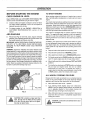
MOWING
TiPS
e
Do not use tire chains when mower housing is attached to
unit
e
Run the engine at FAST speed position.
CAUTION: Look down and behind before
and while backing,, Disengage mower
blades before backing up.
I
Control forward ground speed with shift control lever in
accordance
with type and quantity of grass being
mowed. The more grass to be cut, a slower forward
ground speed should be used When cutting light grass,
forward ground speed can be increased By observing
cutting action of your mower, you can determine the
forward ground speed
Your mower may tend to leave unmowed strips when long
and tender grass is being mowed Tender grass has a high
internal moisture content and is easily depressed by lawn
tractor wheels, and may not always spring back in time to
be cut To overcome this condition, we advise mowing lawn
in a counterclockwise direction, overlapping previous cut,
which allows lifting action of rotating blades to lift grass into
cutting path
When mowing large areas, start in a clockwise direction so
clippings will discharged away from shrubs, fences,
driveways, etc. After one or two rounds, mow in counterclockwise direction until finished (see Fig 10).
e
FIG. 10
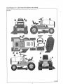
RETRAINING LAWN TO BE CUT WITH MULCHING MOWER-
Be sure your mower is adjusted properly,front-to-rear and
side-to-side,
(see To Level Mower Deck in Service
and Adjustments section).
e
Only cut grassthat
e
Mow grass often. Short grass clippings will decay fast
e
Keep blades sharp Sharp blades will cut better,
e
Your tractor is very maneuverable
back out of dead ends
MULCHING
e
Mow your lawn frequently,
@
For a mulching mower to perform best, we recom m end that
you remove about 1"to 1-1/2" of grass with each cut If your
grass is very thick or lush, you may want to remove as little
as 1/2" on final cut to produce the best possible result. This
could mean that you must mow your lawn every 3-5 days
under certain growing conditions.
@
If the height of the grass should get out of control, we
recommend that you follow instructions for first time mulching to bring lawn back to a manageable height The optF
mum grass height is dependenton grass type and immediate
local growing conditions Consult your local agricultural
extension office for this information
is dry.
MOWING
and can be reversed to
TiPS
To mulch grass with a mulching mower, you will need to do
several things differently than with a conventional mower.
You must change your mowing habits in order to maximize
effectiveness of your mulching mower. This could mean slowing
down the pace that you currently use to mow your lawn to allow
the mulchar extra time to cut and recur the clippings into a fine
mulch. The volume of grass that is under the deck of a mulcher
is greater at any time than it is with a conventional lawn mower
Keep your engine running at full speed (throttle at fast). If
you slow down the engine running speed you will slow blade
speed as well, which will impair the ability of the mower to
cut grass properly
After mowing your lawn, check under the mower deck to be
sure it is clean and free of grass buildup Do not allow the
grass to build up because it will impair ability of mower to cut
properly
WHEN MULCHING LAWN FOR THE FIRST TIME•
Set cutting
direction.
height at highest setting and mow in one
@
Upon completion of first mowing, lower the cutting height to
middle setting and mow a second time at 90 ° to first
cut or in a criss-eross pattern. You can also recut in
same direction by overlapping the center of the mower over
the wheel tracks of the first cut
e
Keep the blade sharp It needs to be kept sharp and free
from nicks to keep from damaging the grass tips while
cutting grass quickly and efficiently
e
Keep your lawn watered,fertilized frequently, and free of
debris.
•
Mulching mower will not perform properly in wet grass Cut
only when it is dry
NOTE: To convert from mulching to conventional lawnmowing
see TO REMOVE
MULCHING
PLUG in CUSTOMER
RESPONSIBILITIES section of this manual
15
CUSTOMER
GENERAL
RESPONSIBILITIES
RECOMMENDATIONS
BEFORE
The warranty on this tractor does not cover items that have been
subjected to operator abuse or negligence, To receive fuUvalue
from warranty, operator must maintain lawn tractor as instructed
in this manual
Some adjustments will need to be made periodically to properly
maintain your unit
EACH
USE
e
Check engine oillevel.
e
Check brake operation.
e
Checktire pressure
e
Check for loose fasteners
All adjustments in the SERVICE AND ADJUSTMENTS section
of this manual should be checked at least once each season
Once a year you should replace spark plug, clean or
replace air filter, and check blades and belts for wear A
new spark plug and clean air filter assure proper air-fuel
mixture and help your engine run better and last longer
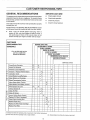
CUSTOMER
RESPONSIBILITIES
BEFORE EACH USE
AFTER FIRST 5 HOURS
SCHEDULE
EVERY 8 HOURS
EVERY 25 HOURS
FILL IN SERVICE DATES
AS YOU COMPLETE
REGULAR SERVICE
EVERY 50 HOURS
EVERY 100 HOURS
BEGINNING EACH SEASON
BEFORE STORAGE
SERVICE DATES
I
i
Check Brake Operation
Check Tire Pressure
Check for Loose Fasteners
Sharpen or Replace Mower Blades
Lubrication Chart
Check Battery Level/Recharqe
Clean Battery and Terminals
Check Transmission
Coolinq
Adjust Blade Belt(s) Tension
Adiust Motion Drive Belt(s) Tension
Check Engine Oil Level
Change Engine Oil
Clean Air Filter
Clean Air Screen
Inspect Muffler/Spark
Arrester
Replace Oil Filter (if equipped)
Clean Engine Cooling Fins
Replace Spark Plug
Replace Air Filter Paper Cartridge
Replace Fuel Filter
I
I
(1) Change more ollen when operaling under a heavy load or in high ambienl tempeIalures
(2) Service more ohen when operating in dirty of dusly conditions
(3) - Replace blades more often when mowing
16
in sandy soil
CUSTOMER
LUBRiCATiON
RESPONSIBILITIES
CHART
Orientation
view only,, Do Not stand
on end.
(_STEERING
GEAR
FRONT AXLE
PIVOT POINTS
WHEEL
BEARINGS
WHEEL
BEARINGS
END OF
DRAG LINK
(_
SECTOR GEAR
) AND BOTTOM OF
STEERING
SHAFT
VIEW FROM LEFT SIDE OF TRACTOR
END OF
(_
UNIVERSAL
JOINT
(SAME ON
BOTH StDES)
STEERING
) PIVOT POINTS
(_MEoFT
(SAME ON
BOTH SIDES)
RIGHT SIDE
MOWER DECK
WHEEL
Q
SAE 30 OR 10W30 MOTOR OIL API _ SG
(_)
GENERAL PURPOSE GREASE
17
SIDE
WER DECK
WHEEL
CUSTOMER RESPONSIBiLITiES
TRACTOR
Always
observe
maintenance.
safety
rules
when
performing
any
BENT TIP
EDGE
BLADE
MOUNTING
SCREWS
BRAKE OPERATION
Your tractor is equipped wit h an edjustable disc brake To check
brake operation do the following:
e
Stop tractor on a level surface and place shift control lever
in NEUTRAL position.
o
Depress brake..clutch pedal enough to latch parking brake
in 2nd notch,
o
Try to push tractor. If you are unable to push tractor, brake
is too tight and should be loosened (see TO ADJUST
TRACTOR BRAKE in SERVICE AND ADJUSTMENTS
section of this manual
o
Depress brake-clutch pedal enough to latch parking brake
in 4th notch
o
Try to push tractor. If you are able to push tractor, brake is
too loose and should be tightened (see TO ADJUST
TRACTOR BRAKE in SERVICE AND ADJUSTMENTS
section of this manual.
SHARP EDGE
Fig. 11
BENT TiP EDGE
BLADE
During tractor operation, check for stopping distance If tractor
requires more than six (6) feet stopping distance at high speed
in highest gear, the brake must be adjusted (see to ADJUST
TRACTOR BRAKE in SERVICE AND ADJUSTMENTS section
SHARP E
of this manual),
SPRING
WASHERS
TIRES
s
Maintain proper air pressure in all tires (See "PRODUCT
SPECIFICATIONS" on page 3 of this manual)
Keep tires free of gasoline, oil, or irrsectcontrol chemicals
which can harm rubber
e
BOLT SHOWN
GRADE
S
Avoid stumps, stones, deep ruts, sharp objects and other
hazards that may cause tire damage.
MOUNTING
SCREW
Q
Fig. 12
CAUTION: BEFORE PERFORMING ANY
SERVICE OR ADJUSTMENTS
e
Do rrot attempt to sharpen blades whilethey are on mower
•
e
Replace bent or damaged blades.
e
•
e
e
e
Fully depress brake-clutch pedal and set
parking brake.
Place shift control lever in NEUTRAL
position.
Place attachment clutch lever In DISENGAGED position,
Turn Ignition key OFF and remove key.
Make sure the blades and all moving
parts have completely stopped,
DO NOT handle blades with bare hands.
Wear gloves or wrap blade with newspaper or other material while removing
or installing blade,
BLADE
BLADE CARE
For best results mower blades must be kept sharp The blades
can be sharpened
with a file Dr on a grinding
wheel We suggest they be sharpened or replaced after every
25 hours or mowing Check blades more often if mowing in
sandy conditions
REMOVAL
(See Figs. 11 and 12)
e
Remove mower deck (see TO REMOVE MOWER
in this section)
DECK
e
Remove blade mounting hardware securing blade.
e
Install new blade with bent tip edges up Blade will not cut
if bent tip edges are not up toward top of mower deck.
e
Secure blade to mower deck with mounting hardware
removed earlier. Be sure all parts are re-assembled in
proper order as shown
e
Tighten blade mounting bolts securely We recommend
using a 10 inchwrench or torque wrench If atorque wrench
is used, torque bolts to between 30 -35 ft Ibs)
IMPORTANT: Blade mounting bolts are Grade 5 heat treated as
shown in Fig 12 inset
18
CUSTOMER
TO SHARPEN
BLADE
RESPONSIBILITIES
(See Fig. 13)
CENTER
Care should be taken to keep blade balanced An unbalanced
blade wil! cause excessive vibration and eventual damage to
mower and engine.
e
Blade can be sharpened with a file or on a grinding wheel
Do not attempt to sharpen while on mower
o
Place center hole of blade over head of the nail or end of
a screwdriver clamped horizontally in a vice If blade is
balanced, it should remain in a horizontal position If either
end of the blade moves downward, sharpen heavy end until
the blade is balanced
TO iNSTALL MULCHING
(See FiG. 14)
HOLE
BLADE
KIT
Fig. 13
Your tractor has a mulching kit To install mulching kit proceed:
e
Position mulching plug on bottom of skid bar and inside
mower deck
e
Install two 5/16-18 x 75 inch carriage bolts, two 5/16 lock
washers and two 5;/16-18 wing nuts Tighten securely
MULCHING PLUG
IMPORTANT: Head of carriage bolt must be to underneath side
of mulching plug
e
To convert from mulchingto
the above steps_
regular lawnmowing,
SKID eAR
reverse
NOTE: If you are not going use your mulching plug store
mulching plug and hardware in a safe place for future use
BATTERY
CARRIAGE
(See Fig. 15)
BOLTS
5/16-18
Fig, 14
Your tractor has a battery charging system which is sufficient for
normal use However, periodic charging of battery with an
automotive charger will extend its life
a
The acid level in each battery should be even with bottoms
of vent wells Add only distilled or iron free water if necessary. Do not over fill
e
Keep battery and terminals clean
e
Keep battery bolts tight.
e
Keep vent caps and small vent holes in caps open
e
Recharge at 6 amps for I hour
TO CLEAN BA'I3ERY
AND TERMINALS
VENT
/
e
Remove terminal
WELL
CELLACID
BATTERY
LEVEL
-
Corrosion and dirt on battery and terminals can cause slow
battery power drain
e
X 75
CUT-AWAY VIEW OF BATTERY
FIG. 15
guard (if so equipped)
V-BELTS
Disconnect BLACK battery cable first then RED battery
cable and remove battery from tractor (see To Remove
Battery in Assembly section of this manual)
Wash battery with solution of four tablespoons of baking
soda to one gallon of water Be careful not to get soda
solution into cells
Check V-belts for deterioration and wear after 100 hours and
replace if required The mower blade drive belt and tractor drive
belts can be adjusted to provide longer belt lite (see TO ADJUST
BLADE DRIVE BELT or TO ADJUST TRACTOR DRIVE BELT
in SERVICE AND ADJUSTMENTS section of this manual)
•
Rinse battery with plain water and dry
TRANSAXLE
e
Clean terminals and battery cable ends with wire brush until
bright
®
Coat terminals with grease or petroleum jelly
e
Reinstall
battery (see TO INSTALL
ASSEMBLY section of this manual)
e
BATTERY
COOLING
Keep transaxle free from build-up of dirt and chaff which can
restrict cooling
in
19
CUSTOMER RESPONSIBILITIES
ENGINE
LUI3RDCATION
Read ENGINE instructions in this section and OPERATION
section of this manual before trying to start engine.
NOTE: Be sure oil has been added to engine crankcase
before trying to start engine.
OIL RECOMMENDATIONS
Only use high quality detergent oi! rated with API service
classification SG Select the oil's SAE viscosity grade according
to your expected operating temperature:
J
VIEW FROM RIGHT-HAND SIDE OF ENGINE
RECOMMENDED
VISCOSITY
GRADES
Fig. 16
32o
:, AR%R
OIL FILL CAP/
DIPSTICK
AIR SCREEN
NOTE:
Although multi-viscosity oils (5W30, 10W30, etc)
improve starting in cold weather, these multi-viscosity oils will
result in increased oil consumption when used above 32°F
Check your engine oil level more frequently to avoid possible
engine damage from running low on oil.
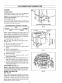
TO CHANGE ENGINE OIL (See Figs 16 & 17)
Raise and lower hood slowly to avoid personal
damage to tractor
injury or
e
Be sure tractor is parked on a level surface,
•
Oil will drain more freely when warm.
e
Clean area around oil fill drain and cap before removing
dipstick
e
Catch oilin a suitable container
e
Remove oil fill cap/dipstick. Be careful not to allow dirt
to enter the engine when changing oil
•
Remove oil drain plug.
e
After oil has drained completely,
plug and tighten securely.
•
Refill engine crankcase with oil through oil fill tube. Pour
slowly. Do not over fill. For approximate capacity see
PRODUCT SPECIFICATIONS on page 3 of this manual
e
Use gauge on oil fill cap/dipstick for checking level Besure
oUfill cap is tightened securely for accurate reading Keep
oil at FULL line on dipstick
AIR SCREEN
replace
Fig= 17
oil drain
(See Fig. 17)
Engine air screen must be kept free of dirt and chaff to
prevent engine damage from overheating Clean air screen with
compressed air to remove dirt and stubborn dried gum fibers
ENGINE COOLING
(See Fig. 18)
ALL DIRT AND DEBRIS
FINS
Fig, 18
Grass, chaff or dirt may clog the rotating screen and the air
cooling system, especially after prolonged service in cutting
tall dry grasses Yearly or every 100 hours, whichever occurs
first, remove the blower housing and clean internal cooling
fins and surfaces as shown to avoid overheating and engine
damage Clean more often if necessary
70
CUSTOMER RESPONSiBiLITiES
AIR FILTER (See Fig. 19)
Your engine will not run properly and may be damaged by
using a dirty air filter, Clean foam pre-cleaner element after
every 25 hours of operation or every season Service paper
cartridge every 100 hours or every season, whichever occurs
first Service air cleaner more often under dusty conditions
e
AER CLEANER
COVER
WING NUTS
_
COVER PLATE
Remove screw and air cleaner cover
,_ ;
TO SERVICE FOAM PRE-CLEANERe
Remove foam pre-cleaner by sliding it off the cartridge
e
Wash foam pre-cleaner in liquid detergent and water
•
Squeeze foam pre-cleaner
e
Saturate foam pre-cleaner in engine oil. Wrap foam precleaner in clean, absorbent cloth and squeeze to remove
ALL EXCESS oil
e
Reinstall foam pre-cleaner
®
Reinstall air cleaner cover and tighten knobs securely
FOAM
'_E-CLEANER
'*'-----
CARTRIDGE
.,_
CARBURETOR
SHIELD
dryina clean cloth_
over cartridge
BODY
TO SERVICE CARTRIDGE®
Remove wing nuts and cover plate
®
Remove cartridge
surface
•
If very dirty, replace or wash in a non-sudsing detergent
and warm water solution. Rinse thoroughly with water
from inside out until water runs clear Let cartridge dry
thoroughly before using.
®
Reinstall cartridge, cover plate and wing nuts.
e
Reinstall air cleaner cover and tighten knob securely
Fig. 19
and clean by tapping gently on flat
FUEL FILTER
IMPORTANT:
PETROLEUM
SOLVENTS,
SUCH AS
KEROSENE, ARE NOT TO BE USED TO CLEAN CARTRIDGE. DO NOT OIL CARTRIDGE DO NOT USE PRESSURIZED AIR TO CLEAN OR DRY CARTRIDGE
CLAMP
CLAMP
MUFFLER
Inspect and replace corroded muffler and spark attester (if so
equipped) as it could create a fire hazard and/or damage
SPARK
Fig. 20
CLEANING
PLUGS
Replace spark plugs at the beginning of each mowing
season or after every 100 hours of use, whichever comes
first Spark plug type and gap setting is shown in PRODUCT
SPECIFICATIONS on page 3 of this manual
IN-LINE
FUEL FILTER
(See Fig. 20)
With engine cool, remove filter and plug fuel line sections
e
Place new fuelfilter in position in fuel line with arrow pointing
towards carburetor,
e
Be sure there are no fuel line leaks and clamps are properly
positioned
e
Immediately wipe up any spilled gasoline
Clean engine, battery, seat, transaxle, finish, etc of all
foreign matter
@
Keep finished surfaces and wheels free of all gasoline, oil,
etc
e
Protect painted surfaces with automotive type wax
We do not recommend using a garden hose to clean your
tractor unless electrical
system, muffler, air filter and
carburetor are covered to keep water out Water in engine can
shorten engine life
Fuel filter should be replaced once each season If fuel filter
becomes clogged, obstructing fuel flow to carburetor, replacement is required Make sure new filter is installed with
the IN marking toward the tank and the OUT marking toward
the engine, Check fuel system components frequently and
replace any parts showing wear or cracks
•
o
21
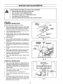
SERVICE AND ADJUSTMENTS
CAUTION: BEFORE PERFORMING ANY SERVICE OR ADJUSTMENTS
•
Depress brake-clutch pedal and set parking brake°
e
Place shift control lever in NEUTRAL position.
e
Place attachment clutch lever in DISENGAGED posittom
e
Turn Ignltlon key OFF and remove key.
e
Make sure the blades and all moving parts have completely stopped.
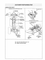
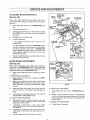
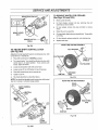
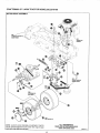
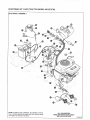
TRACTOR
TO REMOVE
FRONT
MOUNTING
BRACKET
MOWER DECK
Remove mower deck from right side of tractor
e
Place cutting height adjustment pedal in lowest cutting
position by moving memory rod to position 1 and pressing
pedal latch to release cutting height adjustment pedal_
•
Turn front wheels all the way to the left to allow mower deck
hitch to slide past dght front wheel
•
Remove hairpin cotter from mower deck hitch and
remove deck hitch rod from top holes of the front mounting
bracket (see Fig 21)
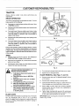
e
Lower deck hitch
e
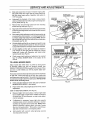
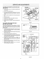
Remove hairpin cotter and Flatwasher from hanger pin of
right rear lift arm and slide off right mower deck lift bracket
(see Fig. 22)
•
Remove hairpin cotter and Flatwasher from hanger pin of
left rear lift arm and slide off left mower deck lift bracket (see
Fig. 22)
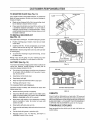
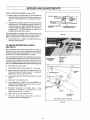
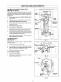
e
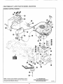
Pull lower engine pulley belt guides away from pulley (see
Fig. 23)
•
Move mower deck forward arrd remove mower deck drive
belt from lower engine pulley Reposition belt guides
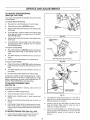
e
Disconnect mower deck engagement cable from mower
clutch cable spring (see Fig_ 24).
e
Place cutting height adjustment pedal in highest cutting
position
•
Puit mower deck out from under right side of tractor.
HAIRPIN
MOWER DECK
H_CH
VIEW FROM FRONT OF TRACTOR
FIG. 21
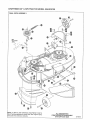
MOWER DECK
LIFT BRACKET
(RIGHT SIDE)
HANGER
PIN
REAR LIFT ARM
(RIGHT SIDE)
FLATWASHER
HAIRPIN
COTTER
VIEW FROM RIGHT SIDE OF TRACTOR
FIG. 22
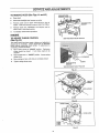
TO INSTALL
MOWER DECK
o
Place cutting height adjustment in highest position by
pressing cutting height adjustment pedal all the way down
until it latches If cutting height is not in highest position, the
deck brackets will hit the lift arms while sliding the deck
under the tractor
o
Place mower deck on right side
chute deflector away from tractor
o
Turn front wheels of tractor to maximum left turn
o
Lift deck hitch and slide deck under tractor to a centered
position,
o
From left side of tractor, slide deck rearward Then connect
mower deck engagement cable to mower clutch cable
spring (see Fig 24). Be sure open side of spring end is
poieted down (see Fig 24 inset)
of tractor
LOWER
PULLEY
ENGINE
BELT GUIDES
with
LOWER
ENGINE PULLEY
FIGo23
22
SERWCE AND ADJUSTMENTS
Slide deck toward front of tractor Pull lower engine pulley
belt guides away from engine and slip mower deck drive
belt onto lower engine pulley Reposition belt guides to
1/16" from pulley
0
MOWER DECK
ENGAGEMENT
Remove hitch rod and hairpin cotter from fronl mounting
bracket and lay aside (see Fig 21)
'
Align holes in the mower deck hitch with the top set of holes
in the front mounting bracket and reinstall the hitch rod and
hairpin cotter
Place cutting height adjustment pedal in lowest position by
moving memory rod to position 1 and pressing pedal latch
to release cutting height adjustment pedal_ NOTE: Be sure
left and right lift arms are to the inside of left and right deck
lift brackets (see Fig 22)
e
Lift deck slightly and flex left rear hanger pin inward to snap
hanger pin into left deck lift bracket slot Secure hanger pin
in place with Flatwasher and hairpin cotter removed earlier
e
Lift deck slightly and flex right rear hanger pin inward to
snap hanger pin into right deck lift bracket slot Secure
hanger pin in place with Flatwasher and hairpin cotter
removed earlier (see Fig. 22)
o
Check mower deck leveling and adjustment as required
See TO LEVEL MOWER DECK in this section of the
manual
TO LEVEL MOWER
MOWER DECK
BELT GUARD
OPEN SIDE
HOOK END
Underneath the footrests of the tractor, remove hairpin
cotters and flatwashers from left and right hand hanger pins
and lay aside (see Fig 22)
O
CABLE
IDLER PULLEY
_._
DECK
DRIVE
BELT
HITCH
FIG. 24
DECK
Adjust mower deck while tractor is parked on level ground
or driveway
Make sure tires are properly inflated (see
PRODUCT SPECIFICATIONS on page 3 of this manual) If tires
are over or under inflated, you will not properly adjust your
mower deck.
The tractor main frame should be level across front from left side
to right side If main frame will not sit level, two outside axle
mounting screws may be too tight The outside mounting screws
must be loose enough to allow front axle to pivot NOTE: Do Not
loosen center mounting screw.
®
Check and adjust height of mower deck (see TO ADJUST
MOWER DECK HEIGHT in this section)
e
Place mower deck cutting height adjustment in No 2 for all
adjustments
SIDE-TO-SIDE
ADJUSTMENT
FRONT OF DECK
Fig. 25
( See Fig 25)
Measure height, from level surface, of left and right blade
tips at outside edge of mower deck If blades are equal or
not more than 1/8 inch difference, no side-to-side adjustment is necessary_
If adjustment is necessary, loosen right side eccentric
mounting screw and turn eccentric clockwise or counterclockwise as required to level mower deck NOTEr When
groove on eccentric is pointing down. right side of mower
deck is at its lowest position When groove is pointing up.
right side of mower deck is at its highest position
e
Hold eccentric with a wrench while lightening
mounting screws securely
eccentric
23
SERVICE AND ADJUSTMENTS
FRONT-TO-REAR
ADJUSTMENT
( See Fig 26B)
Measure height, from level surface, of right side blade tips
at fro nt and rear of mower deck If distances are equal or net
more than 1/8 inch lower in front, no adjustment is neces*
sary
FRONT ADJUSTMENT
ECCE
GROOVE_
If adjustment is necessary, loosen front eccentric mounting
screws and turn front adjustment eccentric clockwise or
counterclockwise as required NOTE: When groove on
eccentric is pointed straight forward, front of mower deck is
at lowest poinL Turn both eccentrics so grooves are
pointing same direction (up or down)
MOWER DECK MOUNTING
BRACKET
If more adjustment is necessary, front of mower deck may be
raised or lowered by relocating eccentric mounting screws in
higher or lower position on mower deck mounting bracket
•
MOWER DECK LEVELING
ADJUSTMENT
HOLES
FIG= 26
Hold eccentric with a wrench while tightening eccentric
mounting screws securely
TO ADJUST MOWER
(See Fig. 27)
DECK HEIGHT
Before making any mower deck height adjustments check air
pressure in all four tires All tires must be properly inflated for
mower deck height to be properly adjusted For recommended
air pressure, see "Product Specifications" on page 3
The main frame on the lawn tractor should be level across the
front from left side to right side If main frame will not sit level, the
two outside axle mounting screws may be too tight The two
outside mounting screws must be loose enough to allow front
axle to pivot NOTE: Do Not loosen center mounting screw.
®
Place tractor on a level surface
e
Place cutting height in lowest position (No 1 see inset)
e
Measure height of mower deck from bottom edge of left
front corner to ground Height should be 1-3/4 inches If
adjustment is necessary, go to next step.
o
Locate adjustment nut near left mower deck lift arm (see
Fig. 27)
e
Loosen jam nut on adjustment rod
•
Turn adjustment nut to obtain 1-3/4 inches NOTE: Turn
adjustment nut clockwise to raise mower deck or counterclockwise to lower mower deck
•
Re-check measurement
as outlined above If more
adjustment
is necessary,
turn adjustment nut until
height of mower deck is 1-3/4 inches
e
Tighten jam nut up against adjustment nut
e
Check and adjust level of mower deck as outlined in
paragraph TO LEVEL MOWER DECK
MEMORY
CUTTING
HEIGHT
ADJUSTMENT
PEDAL
ROD
(CUTTING
HEIGHT
POSITION
NO 1)
.L- _L,__.__
,.-',
ADJUSTMENT
_
"ROD
_
JAMNUT
/_..
MOWERDECK
LIFTARM
VIEW FROM LEFT SIDE OF TRACTOR
FIG. 27
24
SERV#CE AND ADJUSTMENTS
TO ADJUST
BLADE
DRIVE BELT
MOWER DECK
CABLE
(See Fig. 28)
ENGAGEMENT
MOWER DECK
BELT GUARD
When mower blade drive belt slips and blades will net turn
at full speed when mowing, the blade drive belt should be
tightened
CdN_
MOWER
o
Place attachment
tion
e
Loosen idler pulley hex nut
o
Slide idler pulley toward rear of mower deck to tighten
belt NOTE: Only a small amount of movement should
be required
o
Re-tighten hex nut on idler pulley
e
To check adjustment:
a Start engine
position FAST
clutch lever in DISENGAGED
and place
throttle
control
posi-
RIGHT HAND
QUILL
ASSEMBLY
":
BELT RETAINER
lever in
_
IDLERPULLEY
HEXNUT
RAK_AD
BRAK
n°D
To loosen blade drive belt, loosen idler pulley and move
toward front of mower deck
BLADE
DRIVE
BELT
LOCKNUT
b. Place attachment clutch lever in ENGAGED position
and allow sufficient time for blades to run to full speed,
then place attachment clutch lever in DISENGAGED
position Blades should stop within a few seconds and
remain stopped, tf blades do not stop or tend to creep,
adjustment is too tight.
o
CLUTCH
CABLE SPRIN,.,_--
INSET A
A
E ARM
BRAKEADJUSTMENT
(See Fig. 28)
Blade brakes should stop mower blades when attachment
clutch lever is in DISENGAGED position Blade brake pads
should not come in contact with quill assemblies when
attachment clutch lever is in ENGAGED position_
e
Place cutting height adjustment in lowest cut position
(No,1)_
TO CHECK RIGHT HAND BRAKE o
Move attachment chJtch lever backward to DISENGAGED position.
o
e
e
INSET B
Begin to move attachment clutch lever forward toward
ENGAGED position and check distance lever moves
before brake pad, on right hand quill assembly, begins
to move.
Fig. 28
TO CHECK LEFT HAND BRAKE -
Attachment clutch lever should move at least 3/4 inch,
but not more than 1 inch, before brake pad begins to
move
e
If the distance is not between 3/4 and 1 inch, (see TO
ADJUST RIGHT HAND BRAKE below),
Locknut, on end of brake rod, should be approximately
!/8 inch from brake pad mounting bracket with left hand
brake pad against pulley of left hand quill assembly (See
Fig 28, inset A)
TO ADJUST RIGHT HAND BRAKE e
Note which one of five holes on front of idler arm
extension is used for attaching mower clutch cable
spring (see Fig 28, inset B)
e
If distance is more than 1 inch, move mower
clutch cable spring to a hole toward bolts holding idler
arm extension
e
If distance is less than 3/4 inch, move mower clutch
cable spring to a hole toward free end of idler arm extension.
e
Re-check right hand brake and adjust if required
Place attachment clutch lever in DISENGAGED position
TO ADJUST LEFT HAND BRAKE e
el::
Adjust Iocknut if necessary.
SERWCE
TO REPLACE
(See Fig. 29)
MOWER
BLADE
AND ADJUSTMENTS
DRIVE BELT
e
Remove mower deck (see TO REMOVE MOWER DECK
in this section
e
Remove mower deck belt guard
e
Note position of belt retainer on idler pulley so it can be can
be repositioned properly after belt installation Loosen idler
pulley
e
Remove old belt and replace with a new original equipment
belt
e
Reinstall beltguard
e
Reposition belt retainer and re-tighten idler pulley
•
Reinstall mower deck assembly
e
Adjust belt (see TO ADJUST TRACTOR
below)
MOWER DECK
ENGAGEMENT CABLE
MOWER CLUTCH
CABLE SPRING
IDLER PULLEY
BELT RETAINER
MOWER DECK
DRIVE BELT
DRIVE BELT
Fig, 29
TO ADJUST TRACTOR DRIVE BELT
(See Figs. 30A and 30B)
The drive belt is kept tight by a spring attached to the brakeclutch pedal assembly
When the drive belt is properly
adjusted, the brake-clutch pedal should appear as shown in fully
released position
e
The brake-clutch pedalshould appear as showein Fig 30A
when in the fully released position If not, then the following
adjustment is necessary
e
Depress the brake-clutch pedal enough to latch the parking
brake in the 3rd notch
e
Loosen clutching idler pulley mountieg screw
e
If brake-clutch pedal was too far forward, slide idler pulley
in toward engine pulley, tf pedal was too far rearward, slide
idler pulley away from engine pulley
e
Re-tighten idler pulley mounting screw NOTE: Belt
retainer should pointtoward position where runeieg board
meets main frame
e
Release brake-clutch pedal and re-check pedal for proper
position and readjust if necessary
Check tractor brake adjustment
TRACTOR BRAKE in this section)
MOWERDECK
BELT GUARD
(see
PEDAL
BRAKE-CLUTCH
Fig, 3OA
BELT RETAINER
CLUTCHING
IDLER
PULLEY
MOUNTING
SCREW
TO ADJUST
3rd
NOTCH
Fig, 30B
26
SERWCE AND ADJUSTMENTS
TO REPLACE TRACTOR
(See Figs. 31 and 32)
DRIVE BELT
Odantatlon
LOWER ENGINE
BELT GUIDES
Your tractor uses v-belts made of special compounds Ifany belt
becomes worn or breaks, replace with original equipment belt
(see REPAIR PARTS section of this manual) NEVER USE A
SUBSTITUTE
e
Remove mower deck (see TO REMOVE MOWER
in this section).
e
Fully depress brake-clutch pedal and set parking brake
•
Loosen clutching idler pulley mounting screw
e
Pal! belt retainer away from pulley and remove belt from
clutching idler pulley_
•
Remove belt from engine pulley.
e
Remove belt from transaxle pulley,
e
Replace belt by reversing above instructions, Be sure belt
is installed to inside of upper engine pulley belt guide
•
Before repositioning and tightening clutching idler pulley
and belt retainer, adjust tractor drive belt (see TO ADJUST
TRACTOR DRIVE BELT in this section)
®
Check tractor brake adjustment
TRACTOR BRAKE in this section)
viow onty. Do Not stand on end
PULLEY
LOWER
ENGINE
PULLEY
DECK
ENGINE
PULLEY
BELT
RETAINER
PULLEY
BELT GUIDE
CLUTCHING
IDLER
PULLEY
TRANSAXLE
PULLEY
_'
(see TO ADJUST
TO ADJUST SEAT
(See Fig. 33)
Fig. 31
The seat can be adjusted forward or rearward to desired
operator's position
e
Raise rear of seat to horizontal position
e
Loosen (do not remove) four hex head screws in seat plate
e
Pull up on seat to move it toward rear of tractor, or push
down on seat to move to toward front of tractor
e
Tighten hex head screws in seat plate
)BELT
"J
i RETAI_
If more adjustment is required:
e
Remove seat and seat plate,
e
Install seat and seat plate in either forward or backward
holes of seat support bracket
_.
I
CLUTCHING IDLER PULLEY
MOUNTING SCREW
L
Fig. 32
SEAT PLATE
SEAT PLATE
BRACKET MOUNTINC
HOLES
Fig,, 33
27
SEAT PLATE
BRACKET
SERVICE AND ADJUSTMENTS
TO ADJUST
TRACTOR
BRAKE
\
(See Figs. 34A & 34B)
Your tractor is equipped with an adjustable disc brake mounted
on the transaxle
TO CHECK BRAKE OPERATION •
Stop tractor on a hard fiat surface and turn off engine
e
Place shift control lever in NEUTRAL position
e
Depress brake-clutch pedal enough to latch parking brake
in 2nd notch
•
Try to push tractor If you are unable to push tractor, brake
is too tight and should be loosened (see TO ADJUST
TIGHT BRAKE below)
e
Depress brake-clutch pedal enough to latch parking brake
in 4th notch
e
BRAKE
ADJUSTING
NUT
--_
Fig. 34A
PARKING BRAKE
LATCH
Try to push tractor If you are able to push tractor, brake is
too loose and should be tightened (see TO ADJUST
LOOSE BRAKE below)
TO ADJUST LOOSE BRAKE NOTCHES
e
Place shift controllever in NEUTRAL position and depress
brake-clutch pedal enough to latch parking brake in 4th
notch
e
Turn brake adjusting nut clockwise until you cannot push
tractor
e
Re-check tractor brake adjustment as outlined above
BRAKErCLUTCH
PEDAL
VIEW FROM RIGHT SIDE OF TRACTOR
Fig° 34B
TO ADJUST TIGHT BRAKE •
Place shift controllever in NEUTRAL position and depress
brake-clutch pedal enough to latch parking brake in 2nd
notch
e
Turn brake adjusting nut counter-clockwise
push tractor.
e
Re-check tractor brake adjustment as outlined above
until you can
During tractor operation, check for stopping distance If tractor
requires more than six (6) feet for stopping distance at high
speed in highest gear, the brake must be adjusted (see TO
ADJUST TRACTOR BRAKE as described above)
TO ADJUST STEERING
(See Fig. 35)
If excessive play develops
sector gears as follows:
GEAR
in steering,
MOUNTING
SCREWS
adjust pinion and
e
Position front wheels straight forward
e
Arrows should align in pinion and sector gear
e
Slightly loosen mounting screws in lower steering shaft
bearing
e
Move lower steering bearing toward back of tractor, as
needed
e
Hold bearing in place, tighten mounting screws securely
Use a 10-inch wrench or a torque wrench If torque wrench
is used, torque mounting screws to between 30 and 35 foot
pounds
TO ADJUST
o
BRAKE
SHAFT
BEARING
Fig. 35
ROD (See Fig. 36A)
Check tractor drive belt for proper adjustment (see TO
ADJUST TRACTOR DRIVE BELT in this section)
28
@
The brake-clutch pedal should appear as in Fig 30A on
page 26, when in the fully released position If not, then the
following adjustment is necessary
@
Loosen the two jam nuts that attach the brake rod to the
brake rod bracket Adjust until the brake lever bolt is
centered in the brake rod bracket
O
Check TO START ENGINE in the OPERATION section
and TO ADJUST TRACTOR BRAKE in the SERVICE AND
ADJUSTMENTS
section of this manual ior proper
operation
SERVICE AND ADJUSTMENTS
TO REMOVE
,'RARO0
SRACK
_
FOR
REPAnRS
(See Figs. 37A and 37B)
BRAKE LE
BOLT
WHEEL
e
Block up axle securely
e
On front wheels, remove hub cap, retaining
washer(s) to remove wheel
e
On rear wheels, remove hub cap and bolts to remove
wheel
e
Repair tire and re-assemble
e
On rear wheels, align holes and reinstall bolts Torque bolts
to 50 It Ibs
e
On front wheels, replace washer(s), and retaining ring
_:_
BRAKE-CLUTCH
ring and
Replace hub caps.
PEDAL
'_
,,_
FRONT TIRE AND RIM ASSEMBLY
Fig,, 36A
TO ADJUST SHIFT CONTROL
(See Fig. 36B)
LEVER
Adjustment is only required if neutral is not obtained when shift
control lever is in neutral slot
e
Place shift control lever in NEUTRAL position
e
Try to push tractOrrYou should be able to push when shift
control lever is in neutral position
If you cannot push
tractor, adjust as follows
e
Locate neutral position with shift control lever.
•
Loosen screw 'A' on shift bracket on top of transaxle
e
Place shift control lever into the neutral slot
e
Tighten screw'A'
e
Re-check adjustment as described above
FELT WASHER
FLATWASHER
FRONTAXLE
SPINDLE
FLATWASHER
HUB CAP
RETAINER
RING
Fig,, 37A
NOTE: You should not be able to push tractor when shift control
lever is in reverse or a forward range position.
REAR TIRE AND RIM ASSEMBLY
REAR
SHIFT CONTROL
LEVER
NEUTRAL
SLOT
REAR WHEEL
HUB
BOLTS
HUB CAP
Fig. 37B
SHIFT
LEVER
BRACKET
Fig,, 36B
SERVICE
AND ADJUSTMENTS
TO START ENGINE WiTH A WEAK
BATTERY (See Fig. 38)
NEGATIVE(-)
TERMINAL
RUBBER
POSITIVE(+)
TERMINAL
CAUTION:
Lead-acid batteries generate
explosive gases. Keep sparks, flame and
smoking materials away from batteries.
Always wear eye protection when around
batteries.
If your battery is too weak to start the engine, it should be
recharged If "jumper cables" are used for emergency starting
follow this procedure
IMPORTANT: YOUR TRACTOR IS EQUIPPED WITH A 12
VOLT NEGATIVE GROUNDED SYSTEM OTHER VEHICLE
MUST ALSO BE A 12 VOLT NEGATIVE GROUNDED
SYSTEM DO NOT USE YOUR TRACTOR BATTERY TO
START OTHER VEHICLES_
Fig. 38
TO ATTACH JUMPER CABLES e
Push battery boot away from POSITIVE (+) terminal
e
Connect RED (+) cable to POSITIVE (+) terminat
battery, taking care not to short against chassis
e
Connect BLACK (-) cable to NEGATIVE
battery.
on
(-) terminal on
TO REMOVE CABLES, REVERSE ORDER ®
BLACK (-) cable from battery.
•
RED (+) cable from battery
TO REPLACE
FUSE (See Fig. 39)
e
Raise hood
e
Locate fuse holder under clash
e
Remove fuse and replace with a 15 amp automotivetype plug in fuse (see REPAIR PARTS section for more
information).
DASH
TO REPLACE
(See Fig. 40)
HEADLIGHT
FUEL TANK
FUSE HOLDER
BULB
FIG. 39
e
Raise heed NOTE: Do not remove plastic headlight lens
when replacing headlight bulb
e
Turn headlight harness (holding bulb) 1/4 turn counterclockwise and remove
•
Pull bulb out (do not unscrew)
•
Replace headlight harness and turn 1/4 turn clockwise to
lock in place,
e
Close hood
INTERLOCKS
WIRE HARNESS
HOOD
HEADLIGHT
LENS
Push in new bulb
AND RELAYS
Loose or damaged wiring may cause your tractor to run poorly,
stop running, or prevent it from starting
e
Check wiring, See electrical wiring diagram in the REPAIR
PARTS section of this manual
BULB
Fig° 40
qn
HEADLIGHT
HARNESS
SOOT
SERVICE AND ADJUSTMENTS
TO REMOVE
•
HOOD (See Figs. 41 and 42)
HEADLIGHT WIRE
HARNESS CONNECTOR
Raise hood
Disconnect headlight wire harness connecter
e
Remove screw used to atlach hood lanyard to front of
engine, Hold hood securely to prevent hood from falling
•
Remove clevis pins, flatwashers and hairpins used to
attach hood to mounting brackets
e
To reinstall, reverse above procedure
HOOD MOUNTING
BRACKET
ENGINE
)
TO ADJUST CHOKE CONTROL
(See Fig. 43)
VIEW FROM RIGHT SIDE OF TRACTOR
The choke control has been preset at factory and ad ustment
should not be necessary
Check adjustment as described
below before loosening clamp screw
I[ adjustment
is
necessary, proceed as follows
e
Move choke control to "CHOKE" position
Carburetor
choke should be closed
If not choke needs to be
adjusted
e
Place control lever in "CHOKE" position
clamp screw,
e
Move casing and wire until choke is completely closed
e
Tighten casing clamp screw
Loosen casing
HOOD
HAIRPIN
HOOD MOUNTING
BRACKET
VfSW PROM RIGHT SlOE OF TRACTOR
Fig. 41
FRONT OF
HOOD
LANYARD
SCREW
Fig. 42
CHOKE LEVER
Fig. 43
31
SERVICE AND ADJUSTMENTS
THRO'I-I'LE CONTROL
(See Fig. 44)
ADJUSTMENT
"i'HROTTLE r_
The throttle control has been preset at factory and adjustment
should not be necessary
Check adjustment as described
below before loosening clamp screw
If adjustment
is
necessary, proceed as fellows
e
Engine speed is controlled
control lever.
my movement of the throttle
e
Move control "B" to 'FAST"
position
•
Swivel "C" should be against side of quarter circle
TO ADJUSTe
Loosen casing clamp screw "A"
•
Move casing arrd wire in direction shown until swivel is
against side of quarter circle.
•
Re-tighten casing clamp screw "A",
CARBURETOR
(See Fig. 45)
Fig. 44
ADJUSTMENTS
Minor carburetor adjustment may be required to compensate
far differences in fuel, temperature, altitude or load
NOTE: The air cleaner must be assembled to carburetor when
running engine
INITIAL ADJUSTMENT
e
Gently turn the idle mixture screw clockwise until it iust
closes, Turning screw in too far may damage it.
e
Next turn idle mixture screw 1-1/2 turns counterclockwise
This initial adjustment will permit the engine to be started
and warmed up (approximately 5 minutes) prior to final
adjustment,
THROTTLE
IDLE MIXTURE
SCREW
FINAL ADJUSTMENT
e
Start engine and place throttle control in IDLE or SLOW
position
e
Hold throttle lever against idle stop, and adjust idle speed
screw to obtain 1200 to 1400 RPM
•
While still holding throttle lever, turn idle mixture screw
slowly clockwise (lean mixture) until engine iust starts to
slow_
e
Still holding lever, turn screw slowly counterclockwise
(rich mixture) until engine speed "u_ starts to slow
•
Turn screw to midpoint between rich and lean
•
Adjust idle speed screw to obtain 900 to 1200 RPM
e
Release lever
•
If the engine does not accelerate properly, re-adjust
carburetor to a slightly richer mixture.
LEVER
Fig° 45
32
TROUBLESHOOTING
CAUSE
PROBLEM
Will not start
Hard to start
1
2
3
4
5
6
7
1
Fill fuel tank
Engine not _CHOKED" properly
Engine flooded
Bad spark plug
2
3
4
5
6
7
See TO START ENGINE in Operation section
Wait several minutes before attempting to start
Replace spark plug
Clean/replace air filter
Replace fuel filter
Drain fuel tank and carburetor, refill tank with fresh
Loose or damaged wiring
Carburetor out of adjustment
Engine valves out of adjustment
8
9
fO
gasoline and replace fuel filter
Check all wiring
Contact Sears Service Department
Contact Sears Service Department
1
2
3
Dirty air filter
Bad spark plug
Weak or dead battery
Dirty fuel filter
Stale or dirty fuel
Loose or damaged wiring
Carburetor out of adjustment
Engine valves out of adjustment
1
2
3
4
5
6
9
10
Clean/replace air filter
Replace sparkp]ug
Recharge or replace battery
Replace fuel filter
Drain fuel tank and refifi tank with fresh gasoline
Check allwidng
Contact Sears Service Department
Contact Sears Service Department
Corroded battery terminals
Loose or damaged widng
Faulty ignition switch
Faulty solenoid
Faulty operator presence switch(es)
1
2
3
4
5
6
7
8
9
Depress brake-clutch pedal
Disengage mower clutch lever
Recharge or replace battery
Replace fuse
Clean battery terminals
Check a!l widng
Check/replace ignition switch
Check/replace solenoid or starter
Contact Sears Service Department
Weak or dead battery
Corroded battery terminals
Loose or damaged wiring
Faulty solenoid or starter
1
2
3
4.
Recharge or replace battery
Clean battery terminals
Check aft wiring
Checldreplace solenoid or starter
Cutting too much grass/leo fast
Throttle in "CHOKE" position
Build-up of grass, leaves and trash under mower
Dirty air filter
Low oil level/dirty oil
Faulty spark plug
Dirty fuel filter
Stale or dirty fuel
Water in fuel
1
2
3
4
5
6
7
8
9
Set in "Higher Cut" posifion/reduce speed
Adjust throttle control
Clean underside of mower housing
Clean/replace air filter
Check oil level/change oil
Clean and re-gap or change spark plug
1
2
3
4
5
6
7
8
9
Brake-clutch pedal not depressed
Mower clutch ]ever is engaged
Weak or dead battery
Blown fuse
1
2
3
4
1
Loss of power
Out of fuel
8
9
10
5
6
7
8
Engine clicks but
will not start
CORRECTION
Dirty air filter
Dirty fuel filter
Water in fuel
4
Engine will not
turn over
POINTS
2
3
4
5
6
7
8
9
10
11
12
13
14
15
Spark plug wire loose
Dirty engine air screen/fins
Dirty clogged muffler
10
11
12
Loose or damaged wldng
Carburetor out of adjustment
Engine valves out of adjustment
13
14
15
Replace fuel filter
Drain fuel tank and refill tank with fresh gasoline
Drain fuel tank and carburetor, refill tank with fresh
gasoline and replace fuel filter
Connect and tighten spark plug
Clean engine air screen/fins
Clean/replace muffler
Check all wiring
Contact Sears Service Department
Contact Sears Service Department
1
Worn, bent or loose blade
t
Excessive
vibration
2
3
Clutching idler assembl r worn or damaged
Loose/damaged parts
2
3
Replace blade Tighten blade bolt
Replace clutching idler assembly
Tighten loose part(s) Replace damaged parts
Unit will not
1
Sheared or missing engine, transmission or
transaxle pulley(s) key
Transaxle not operable
Relief valve rod incorrectly positioned (Units with
hydrostatic drive transmissions only)
1
Replace key
2
3
Contact Sears Service Department
propel itself when
clutch is engaged
33
Stop unit and place relief valve rod in NORMAL
position
TROUBLESHOOTING
PROBLEM
Unit will not shift
or shifts hard
POINTS
CAUSE
1
Shifting procedure
2
Tractor drive belt and/or brake out of adjustment
2
3
Transax]enotoperatingpreperly
3
1
Faulty operator-safety
1
Check wiring, switches and connections if not
corrected, contact Sears Service Department
1
2
3
Worn, bent or loose blade
Mower deck not level
1
2
Build-up of grass, leaves and trash under mower
3
Replace blade 13ghten blade bolt
Replace blade mandrel
Clean underside of mower housing
Mower blades
1
Obstruction
1
Remove obstruction
will not rotate
2
3
4
Mower drive belt out of adjustment
Word/damaged mower drive belt
Frozen idler pulley
2
3
4
Adiust mower drive belt
Replace mower drive belt
Replace idler pulley
1
2
3
4
5
Bulld-up of grass leaves and trash under mower
Wet grass
Engine speed too slow
Travel speed too fast
Mowing to much grass
1
2
3
4
5
6
Mower deck not level
6
Clean underside of mower housing
Allow grass to dry before mowing
Place throttle control in _FAST" position
Shift to slower speed
Set cutting height to higher setting Then re-cut at
normal setting,
Level mower deck
7
8
9
Low/uneven tire air pressure
Worn, bent or loose blade
7
8
Engine continues
to run when
incorrect
CORRECTION
presence centrol system
1
Check shifting procedure Unit MUST come to a
complete stop before changing directions
Check adjustment of tractor drive belt and/or brake
Adjust if necessary
Contact Sears Service Department
operator leaves
seat with mower
clutch engaged
Poor cut-uneven
Poororno
grassdischarge
10
11
in clutch mechanism
Mower ddve belt worn or out of adjustment
Blades improperly installed
Improper blades used
9
10
11
Check tires for proper air pressure
Replace/sharpen blade Tighten blade bolt
Replace/adjust mower drive belt
Reinstall blades sharp edge down
Replace with blades listed in this manual
1
2
3
4
5
6
7
Mowing wet/high moisture content grass
Mowing too much grass
Mowing too fast
Blades are worn or require sharpening
1
2
3
4
Blade drive belt out of adjustment
Worn or damaged quill assembly(s)
Damaged mower deck housing
5
6
7
Allow grass to dry before mowing
Set cutting height to higher setting
Place transmission control lever in lower setting
Sharpen or replace blades if necessary
Check tension of blade drive belt Adjust if necessary
Replace quil! assembly(s)
Repair of replace mower deck housing
Headllght(s) not
working (if so
equipped)
1
2
3
4
5
Switch is"OFF"
Bulb(s) burned out
Faulty light switch
Loose or damaged wiring
Blown fuse
1
2
3
4
5
Turn switch "ON _
Reptace bulb(s)
Check/replace light switch
Check wiring and connections
Replace fuse
Battery will not
charge
1
2
3
Poor cable connections
Bad battery cells
Faulty regulator (if so equipped)
1
2
3
Check/clean allconnections
Replace battery
Replace regulator
Steering erratic
1
2
Steering sector gear and pinion loose
Worn ball joints
1
2
Check steering sector gear Adjust if necessary
Check ball joints Replace if necessary
Steering
difficulty
1
2
Steering sector gear and pinion tight
Steering pivot points dry
1
2
Check steering sector gear Adjust if necessary
See Lubrication Chart
Mower leaves
unmowed strip
between blades
S TOFtA GE
ENGINE
FUEL SYSTEM
Immediately prepare your unit for storage at the end of the
season or if the unit will not be used for 30 days or more
IMPORTANT:
IT IS IMPORTANT TO PREVENT GUM
DEPOSITS FROM FORMING IN ESSENTIAL FUEL SYSTEM PARTS SUCH AS
THE CARBURETOR, FUEL FILTER, FUEL
HOSE, OR TANK DURING STORAGE
ALSO , EXPERIENCE INDICATES THAT
ALCOHOL-BLENDED
FUELS (CALLED
GASOHOL
OR USING ETHANOL OR
METHANOL) CAN A'FFRACT MOISTURE
WHICH LEADS TO SEPARATION AND
FORMATION OF ACIDS DURING STORAGE
ACIDIC GAS CAN DAMAGE THE
FUEL SYSTEM OF AN ENGINE WHILE IN
STORAGE
DANGER
Never store the engine with fuel indoors or in a poorly
ventilated enclosure, where fuel fumes may reach an
open flame, spark or pilot light as on a furnace, water
heater, clothes dryer, etc
Handle the gasoline carefully
It is highly flammable and
careless use could result in serious fire damage to your
person and/or property
Drain the fuel into an approved container outdoors away
from an open flame.
TRACTOR
Remove mower deck from tractor for winter storage
When
mower deck is to be stored for a period of time, clean it thoroughly, remove all dirt, grease, leaves, etc Give blades and
underside of mower deck housing a good coat of grease or
rust preventative. Store in a clean, dry area.
e
Clean entire tractor (See CLEANING in CUSTOMER
RESPONSIBILITIES
section of this manual)
Lubricate
(see CUSTOMER
section of this manual)
O
Be sure all nuts, bolts and screws are securely fastened
Inspect moving parts for damage, breakage and wear
Replace if necessary
RESPONSIBILITIES
Touch up all rusted or chipped
lightly before painting
paint surface;
Drain fuel tank
e
Start engine and let it run until the fuel
carburetor are empty
e
Never use engine or carburetor cleaner products in fuel
tank or permanent damage may occur
e
Use fresh fuel next season
lines and
NOTE: Fuel stabilizer (such as STA-BIL) is an acceptable
alternative in minimizing formation of fuel gum deposits during
storage.
Add stabilizer to gasoline in fuel tank or storage
container Always follow mix ratio found in stabilizer container
Run engine as least 10 minutes after adding stabilizer to allow
stabilizer to reach the carburetor
Do not drain gas tank and
carburetor if using stabilizer.
Inspect and replace belts, if necessary (See belt
replacement
instructions
in the SERVICE
AND
ADJUSTMENTS section of this manual)
O
e
ENGINE
OIL
Drain oil (with engine warm) and replace with clean engine oil
(See ENGINE IN CUSTOMER RESPONSIBILITIES
section
of this manual)
sand
CYLINDERS
BATTERY
e
Remove spark plugs
o
Fully charge battery for storage
•
o
After a period of time in storage, battery may require
recharging
Pour one ounce of oil through spark plug holes into
cylinders
e
Turn ignition key to START position for a few seconds to
distribute oil
e
Replace with new spark plugs
O
To help prevent corrosion and power leakage during
long periods of storage, battery cables should be
disconnected and battery cleaned thoroughly (see TO
CLEAN BATTERY AND TERMINALS in CUSTOMER
RESPONSIBILITIES
O
OTHER
section of this manual)
After cleaning, leave cables disconnected and place
cables where they cannot come in contact with battery
terminals_
e
Do not store gasoline from one season to another
•
Replace your gasoline can if your can starts to rust
Rust and/or dirt in your gasoline will cause problems
•
If possible, store your tractor indoors and cover it to give
protection from dust and dirt
Cover tractor with a suitable protective cover that does
not retain moisture Do not use plastic Plastic cannot
breathe which allows condensation
to form and will
cause your tractor to rust
IMPORTANT:
35
NEVER
COVER
TRACTOR
WHILE
ENGINE AND EXHAUST
AREAS ARE
STILL WARM
CRAFTSMAN
43" LAWN TRACTOR
MODEL
536.2576700
CHASSIS & HOOD ASSEMBLY
REF,
REF.
MOWER
SUSP
HOOD
REF,
STEERING PG.
FRONT AXLE ASSY
NOTE: ALWAYS USE ORIGINAL EQUIPMENT PARTS
Use of service/replacement paris other than original equipment parts may void your warranty
ALL UNNUMBERED
ITEMS ARE INTERCHANGEABLE
WITH OPPOSITE SIDE
36
333142B
CRAFTSMAN
43" LAWN
TRACTOR
MODEL
536.2576700
KEY#
PART#
DESCRIPTION
QTY
1
2
3
4
5
6
7
8
9
10
1!
12
13
14
15
16
17
18
19
20
21
22
23
24
25
26
27
28
29
30
31
32
33
34
35
36
37
38
39
40
41
42
43
44
45
46
47
48
326580-854
314799
310006
309235
323968-853
313541-853
56030
55273
300440
1498
308207
309005
180138
2483
1499
300635
124824
271190
315120*854
46763
35497
995346
324111-830
995346
44811
50352
319718
321810
318139
996307
1502
318304
323295
323293
333143
316043
316881
1501
314967
314966
323044
996425
8260
328042
49050
301452
324491
324492
333342
FRAME, MAIN
.........
FOOT PAD. LH "P-LIFT"
FOOT PAD, RH 22 12LG .
FASTENER, RATCHET BLACK
BRACKET. GRILLE , _
BRACKET. FRONT AXLE
SCREW, 5/16-16X 75WDFLLI_
NUT, 5/16-18 HXWDFLLK
GUIDE, BELT, RIDER ......
NUT, 5/16-18 REGHEXCTRLt_
BOLT, 625X2 18 HHSH 1/2-13
NUT, 1/2-13 HEXJAM CTRLK
SCREW, 3/8-16X3 O0 HHC .......
WASHER, 391DX1 25DX.07 BELLVIL
NUT, 3/8q6 REGHXCTRLK
GUIDE,BELT SHORT 15" WHEEL
NUT, 5/16-!8 HEXJAM
NUT, 3/8-16 HEXKEPS
CONSOLE SOF P-LIFT ...
RIVET, POP ,167DIAX 450LG ST
SCREW 5/16-19X 60 WAHHTAP
SCREW, 1/4-20X 50 WAHHTAP
DASH STEEL ........
SCREW 1/4-20X 50 WAHHTAP
SCREW, 1/4-20X 75 WAHHTAP
NUT, 1/4-20 WDFLLK TOPLOCK
DASH ......................
BUMPER,HOOD/DASH
TOP .........
SCREW, 1f4-20X 63PHPNHD BLACK
WASHER. FLAT ,391X1.0OX 209
NUT, 1/4-20 REGHEXCTRLK .......
SCREW. 1/4-14X 75PHPNHDTAP
HOOD ...........................
SKIRT, HOOD LOWER
............................
GRILLE
....................................
SCREW. 10X1.0 UNSL-HWH-HILO
.......
SCREW, IOX 75 UNSL-HWH-HILO
..........
WASHER, FLAT 203X 56X 040
.........
LENS LH SEARS
....
LENS RH SEARS ....................
PIN, CLEVIS 580X 49/51LGTH
.............
WASHER, FLAT 515X .88X 064
PIN, HAIR 091 DIAXl 66LG
.......
LANYARD. HOOD SEARS ..........................
SCREW, 1/4-10X 75PHPNTAPGR2BK
.......
FOIL, HEAT REFLECTOR ...........................
BUMPERHOOD/DASH
SIDE TOP ...........
BUMPER,HOOD/DASH
SIDE BOTTOM
OWNERS MANUAL
1
1
37
12
2
!
5
5
1
1
1
2
2
2
!
1
1
1
3
2
9
1
2
4
4
1
2
2
4
2
2
1
1
!
8
6
14
1
1
2
2
2
1
1
2
2
4
1
CRAFTSMAN
43" LAWN
TRACTOR
MODEL 536.25"76700
CHASSIS & HOOD ASSEMBLY
.EF
MOTION DRIVE
PAGE
@
®
KEY#23
\
REF.
KEY#1
NOTE: ALWAYS USE ORIGINAL EQUIPMENT PARTS
Use of service/_eplacement parts other than original equipmeet parts may void your warranty
ALLUNNUMBERED
ITEMSAREINTERCHANGEABLE
WITH OPPOSITESIDE
qQ
333142 A
CRAFTSMAN
43" LAWN TRACTOR
MODEL
536.2576700
KEY #
PART#
DESCRIPTION
QTY
64
65
66
67
69
69
70
7!
72
73
74
75
76
78
79
80
81
52
83
84
85
86
87
88
59367-854
310660-854
20507
1498
48901
1495
57153
1341
44811
56907
308654-854
995346
126358
55273
55023
327061_554
48145
150079
120393
1498
321863
180077
120638
120393
PLATE,SEAT .........................
BRACKET, SEAT SUPPORT ........
BOLT, 437X 156 HHSH 5/16-18
NUT, 5/16-18 REGHEXCTRLK
SCREW. 5/16-18X 63WAHHC
NUT, 5/16_15 REGHEXCTRLK
......
SPRING,SEAT 2 63LG.1.49OD BLK
CLAMp, SPRG 1 17"1D BRZN953
SCREW. 1/4-20X .75 WAHHTAP ........
COVER,SEAT SPRING 1 51DX1 0LG
FENDER ........................
SCREW, 1/4-20X .50 WAHHTAP
BOLT, 5/16-18X1 00 CARRLN
......
NUT. 5/16-18 HXWDFLLK ............
TRIM,STRIP,BLACK--SMALL,W/ADH
HITCH,SEARS ............................
SCREW 3/8_16X1 00 WAHHSPTAPPL
SCREW, 5/16-18Xl O0 HHC ....
WASHER. FLAT .344X .69X 065
NUT, 5/16-18 REGHEXCTRLK .............
SEAT V540 CRAFTSMAN W/RED TRIM
SCREW, 5/16-18X 75 HHC ............
WASHER. HVSPTLK 328X 60X.09
WASHER FLAT 344X 69XO65
1
2
2
2
4
4
2
2
2
2
1
4
2
2
75 IN
1
2
2
2
2
1
4
4
4
39
CRAFTSMAN
43" LAWN
MOWER SUSPENSION
TRACTOR
MODEL
536.2576700
ASSEMBLY
SEE
DETAIL "A"
REF.
SOLENOID
REF
KEY#18
CHASSIS & HOOD PG
MAIN FRAME
ALL UNNUMBERED
ITEMS ARE INTERCHANGEABLE
WITH OPPOSITE SIDE
NOTE: ALWAYS USE ORIGINAL EQUIPMENT PARTS
Use of service/replacement parts other than original equipment parts may void your warranty.
4O
322997 H
CRAFTSMAN
43" LAWN TRACTOR
KEY#
1
2
3
4
5
6
7
8
9
10
11
12
13
15
16
17
18
19
20
21
22
23
24
25
26
27
28
29
30
31
32
33
34
35
36
37
38
39
40
41
42
43
44
45
46
47
48
49
50
51
52
53
54
55
56
57
58
59
60
61
62
63
MODEL
536,2576700
PART#
DESCRIPTION
QTY
320075-853
180079
120393
1498
317089
50148
8260
318341
35496
324032
48306
316648
324045
1502
300698-853
180020
1502
324055
120613
35498
57444
322835-853
300169-853
180079
58247
1498
417098
8260
322821
120394
36368
996416
120377
322467
56248-853
57072
!498
314962-853
328596
328771
57072
44108
315342
314829
1499
314489
314792
121222
321385
120394
36368
315341
44811
324036
1502
314969
314837
321837
180077
1498
1288
309235
BRACKET.CLUTCH
ENGAGE LEVER
SCREW, 5/16-18X1 00 HHC . ..
WASHER FLAT .344X .69× 065
NUT, 5/16-18 REGHEXCTRLK
ASSY, CLUTCH LEVER ..............
BEARING FL 5031DX ,63ODX 50
PiN, HAIR O91 DIAX166LG.,
BRACKET, SWITCH ENGAGE , ..
SCREW, 5/16-18X ,75 WAHHTAP
SPRING.CABLE KEEPER 390 ID
PULLEY, POWDER METAL
SPRING .071 X 62X 1288
BOLT, 375X .565 HHSH,,
.
NUT, I/4-20 REGHEXCTRLK
BRACKET FRAME CABLE
SCREW, 1/4-20X 75 HHC
.....
NUT, 1/4-20 REGHEXCTRLK ......
ASSY,CABLE, BLADE ENGAGE
.....
NUT, 1/4-28 HJAM ......................
SCREW, 5/16-18X .75 WAHHTAP
TIE, CABLE BLACK NYLON 5 62L
LIFT ASSY. LH
LIFT ASSY, RH .............
SCREW, 5/16-16X1 00 HHC
NUT ADJUST .................
NUT, 5116-18 REGHEXCTRLK
....
WASHER, FLAT .531X1.06X 063
PIN. HAIR 091 DIAX1 66LG.
.
ROD. ADJUSTING .jr, P-LIFT .....
WASHER, FLAT 406X .81X 065
PIN, HAIR 072 DIAX1 13LG ..........
WASHER, FLAT 391X1 OOX 125
NUT, 3/8-16 REGHX ...................
NUT, 3!8-16 HXHDNYLON INSERT
......
BRACKET, REAR HANG SUSP
....
BOLT, 5/16-18X 63 CARRLN .
NUT, 5/16-18 REGHEXCTRLK
...........
PEDAL ASSY, DECK HEIGHT
PAD, LIFT PEDAL ......
BRACKET, LIFT ARM ..........
BOLT, 5/16-18X 63 CARRLhJ
NUT. 5/16"18 HWDFLCTRLK
LATCH PEDAL LIFT ............
BOLT, 56X.13
HHSH3/6*16
....
NUT, 3/8-16 REGHXCTRLK
SPRING, LIFT LATCH
...........
ROD, PIVOT ........................
PIN, COTTER .090 DIAX 75LG
....
ROD, MEMORY
.................
WASHER, FLAT 405X ,81X 065
............
PiN, HAIR 072 DIAX1 13LG
............
BRACKET, MEMORY ................
SCREW, 1/4"20X .75 WAHHTAP .......
GUIDE, MEMORY ROD " NEW ADJ'T ........
NUT, 1/4"20 REGHEXCTRLK
.......
CAP, MEMORY ROD 361D X 75
SPRING, MEMORY .......................
KNOB,ROUND 1.50 DIA MATTE BLK ......
SCREW, 5/16-18X 75 HHC
.
NUT, 5/16"18 REGHEXCTRLK
BRACKET, CABLE RETAIN
FASTENER, RATCHET
1
2
2
2
1
1
1
1
1
1
1
1
1
1
1
2
2
1
1
1
1
1
!
1
1
1
2
2
1
1
1
1
1
1
2
4
4
1
1
1
4
4
1
1
1
1
1
2
1
4
1
2
4
1
4
1
I
1
1
1
1
1
41
CRAFTSMAN
43"
LAWN
TRACTOR
MODEL
536.2576700
FRONT STEERING ASSEMBLY
REF
CHASSIS & HOOD PG
(STEERING WHEEL
& HARDWARE)
REF
(DASH)
REF
CHASSIS & HOOD PG
(MAIN FRAME)
REF KEY %
REF
CHASSIS & HOOD PG
SUPPOR_
REF.
TIRE TREAD
PAGE
NOTE: ALWAYS USE ORIGINAL EQUIPMENT PARTS
Use of service/replacement
parts other than original
equipment parts may void your warranty
ALL UNNUMBERED
ITEMS ARE INTERCHANGEABLE
WITH OPPOSITE SIDE
328622 B
CRAFTSMAN
43" LAWN
TRACTOR
KEY#
PART#
1
^
lq
1-2
1-3
1-4
1-5
1-6
8
9
10
11
12
13
14
!5
16
17
18
!9
20
20-1
20-2
2043
20-4
20-5
26
27
28
29
30
31
32
33
34
35
36
36-I
36-2
36-3
40
42
43
44
45
46
47
31017O
52407
318539
318544
36625
53373-853
304590
180128
120382
120377
313634
313629
313671*853
315196
274654
302498
323731
71100
323752
321449
124925
57158
272123
302865
46692
120396
120383
271508
318702
302314
302524
315194
2968
20864
321909
24167
39829
321908
TIRE
73840
318550
642
36625
306571
306669
^ ORDER INDIVIDUAL
MODEL
536.2576700
DESCRIPTION
QTY
AXLE.FRONTASBY
LONGSUS4WS
AXLE, FRONT .........
SPINDLE BEARING
_
ABSY.SPINDLE.RH LG
....
ASSYSPINDLE,LH
LG ..............
RING. RETEX 57X 05TRU5133-75
....
AXLE COVER .................................
TIE ROD ASSY 19 81LG W-SECTION
SCREW, 3/8-16Xl 75 HHC
.......
WASHER, REGSPTLK 393X 68X 10
NUT, 3t8-16 REGHX .............
ASSY, SECT GEAR BLK .........
BEARING, SLEV.
IDX ODX ....
SUPPORT.SECTOR
GEAR 4WS
......
SCREW, 1/2-20X3.00 HHC
.....
NUT, 1/2-20 REGHXCTRLK ..............
BEARNIG, SFAL 5001DX. ODX 75_
SCREW, 5/16-24X.75 (TQ 30-35 FT#)
NUT, 5/16-24 REXWDFLLK ............
ASSEMBLY.DRAG
LINK 4WS GEAR
DRAG LINK 625 DIA FOR 4WS
NUT, 3/8-24 REGHEXJAM ............
BALL JOINT 3!8 THD SHORT STUD
NUT, 7/16-20 HXJAM
BALL JOINT 7/16-20 ...............
NUT, 3/8-24 WDFLHLK WHIZ...
WASHER, FLAT .531X1.O6X.095 ...
WASHER, REGSPTLK 459X 78X 12
NUT, 7/16-20 REGHX ..................
SHAFT.STEERING 4WS .SEARS ....
PINION,STEERING .....
PIN DOWEL BTR ......................
WASHER. FLAT 51X1.38X.043.
WASHER, FLAT 504X .75X.059.,
RING. RET E .39X.O4TRU5133-50
....
TIRE & RIM, PU 15X6 0X6 .......
VALVE STEM
RiM, WHEEL
BEARING
REFER TO TIRE TREAD PAGE
WASHER, FLAT 765X1 12X.06 .............
SEAL, FELT 1,56 O.D.Xl/8 THK ....
WASHER, FLAT 755Xl.31X,075
.................
RING, RETEX 57X 05TRU5133*75
..........
HUB CAP .......................................
CLIP.HUBCAP TINN #C25467-O17-4
....
1
1
4
1
1
2
2
1
2
2
2
1
1
1
1
1
1
2
2
1
1
I
1
1
1
1
1
1
1
!
1
1
1
1
1
2
PARTS
43
6
2
2
2
2
8
CRAFTSMAN
43" LAWN TRACTOR
MODEL 536.2576700
REAR STEERING ASSEMBLY
REF
CHASSIS & HOOD PG
(MAIN FRAME
._.,.,
_ .
I
_ _,_:_:_:_
_i,:
-_ _ .-_"._....
t_;
• ,..+
REF
FRONT STEERING PG
(SECTOR GEAR)
NOTE: ALWAYS USE ORIGINAL EQUIPMENT PARTS
Use of service/replacement parts other than original equipment parts may void your warranty
ALL UNNUMBERED
ITEMSAREINTERCHANGEABLE
WITH OPPOSITESIDE
44
326137 C
CRAFTSMAN
43" LAWN TRACTOR
MODEL
536.2576700
KEY#
PART#
DESCRIPTION
QTY
1
2
3
4
5
6
6_1
6_2
6-3
6-4
6-5
8-6
6_7
6-8
6-9
6-!0
6-11
18
19
20
21
22
23
24
25
26
27
28
29
39
31
32
33
34
35
36
37
37q
37-2
3743
37-4
37-5
43
43-1
43-2
43-3
43-4
43*5
49
50
51
52
53
54
55
56
303222_853
180091
120393
1498
35498
326135
314267
12465
12325
320531
12280-853
36311
12289
324578
91682
12321
456722
180079
120393
1498
324514
308719
12319
120394
304115
25177
45602
421051
302594
304116
304122
274654
324638
996307
412349
308720
323634
308447
308399
308384
124925
304260
323635
308446
308399
308384
124925
304960
181646
412349
304120-853
304121-853
39728
181639
120382
419349
BRACKET X-AXLE MTG 4WS
SCREW, 5/16-18X2 50 HHC .......
WASHER, FLAT .344X .69X 065
......
NUT, 5!16-18 REGHEXCTRLK ............
SCREW, 5/16q8X 75 WAHHTAP
U-JOINT, ASM. 4WS LD .................
BRACKET.STEERING
PIVOT DRILLED
BRACKET,STEERING
PIVOT
.....
BRNG, BALL 6203-2AA-3/4 ..............
U-JOINT ASSEMBLY W/ZERK (LONG)
HUB ASSEMBLY ...........................
PIN. GROOVED .250 DIAX1 5OLG
PIN, STEERING HINGE ......
BRACKETASY,STR
PVTqN . .
WASHER, FLAT 765Xl 25X.042
BEARING, FLSH
IDX
ODX .....
PIN, SPRING 250DIAX1 5OLG HVPL
SCREW, 5/16-18Xl OO HHC .....
WASHER, FLAT ,344X .69X 065
NUT, 5/16-18 REGHEXCTRLK
......
ROD ASM.DRAGLINK 4WS BLK
PIVOT. STEERING ..................
BOLT, .562X 340 HHSH 3/8-24 ....
WASHER, FLAT .406X 81X.065
....
SPACER, STEERING SHAFT . .
WASHER. FLAT 765X1.19X 048
WASHER, FLAT .333X 87X 119
SCREW, 5/16-24X1.00 HHC
FOLLOWER,ROLLER
CAM YOKE ROLLER ..
BOLT, 625 X1.175HHSH ..
NUT, 1/2-20 REGHXCTRLK.
BOLT, .265X 980 HHSH 3/8-24 .
WASHER, FLAT .391Xl O0X 209
NUT, 3/8-24 HXCTRLK ...........
SHAFT, STEERING PIVOT (ZN)
TIE ROD, ASSYRH EURO 4WS
ROD. TIE 1/2"D X 8.12LG ....
NUT. 3/8-24 LH THD REGHJAM
BALL JOINT LH 3/8-24 ,.
NUT. 3/8-24 REGHEXJAM
BALL JOINT,RH 3/8-24 ..
TIE ROD, ASSYLH 4WS.
ROD, TIE 1/2"D X 9.75LG .....
NUT, 3/8-24 LH THD REGHJAM
BALL JOINT LR 3/8-24 .....
NUT. 3!8-24 REGHEXJAM
BALL JOINT,RH 3/8-24...
SCREW, 3/8-24Xl 75 HHC
NUT, 3/8-24 HXCTRLK ...........
ARM REAR WHEEL STEEF R H
ARM, REAR WHEEL STEER L.H
SCREW 3/8-16X 75WAHHTAP
SCREW, 3/8-24Xl .25 HHC
.......
WASHER, REGSPTLK 393X 68X 10
NUT. 3/8-24 HXCTRLK
2
4
4
4
4
2
1
1
2
1
1
1
2
1
1
1
2
8
16
8
1
1
1
1
1
2
1
1
1
1
1
1
46
1
1
1
1
1
1
1
1
1
1
1
1
1
1
1
1
1
4
2
2
2
CRAFTSMAN
43"
LAWN
TRACTOR
MODEL
536.2576700
MOTION DRIVE ASSEMBLY
ELECTRICAL PAGE
GROUND WIRE
& HARDWARE
,:,
NOTE
S
RIGINAL EQUIPMENT PA
Use of service/replacement
parts other than original _RqTiS:
ment parts may void your warranty.
HEF
CHASSIS &
HOOD PAGE
ALL UNNUMBERED
ITEMS ARE INTERCHANGEABLE
WITH OPPOSITE SIDE
328041B
CRAFTSMAN
43" LAWN TRACTOR
MODEL
536.2576700
KEY#
PART#
DESCRIPTION
QTY
1
2
3
4
5
6
7
8
9
10
11
12
13
14
15
16
17
18
19
20
21
22
23
24
25
26
27
28
29
30
31
32
33
34
35
36
37
38
39
40
41
42
43
44
45
46
47
48
49
50
303109
50795
22053
3!4120._
180091
120393
1498
323739
35498
120838
180079
120393
1498
50947
180138
138538
1498
319111
310347-853
180079
996416
1498
310347-853
57259
996416
1498
310356
180Q20
1502
324798
310265
137185
120238
306690
314965
180124
120382
1499
309637
180124
120394
1499
57157
56255
311257-853
311209
311331
1341
311331
TRANSAXLE P930-042 6SP4WSLF
PULLEY, 6.60D V4L T/A ...........
KEY, HFPRO 606 .75DIAX 187WD.
RING, RETEX 58X.035TRU5100-62
BELT, V 4L 87 25 4WS LF ......
SCREW, 5716-18X2 50 HHC ....
WASHER, FLAT .344X .69X 065
NUT, 5/16-18 REGHEXCTRLK
BRKT, STABILIZER BLK..
SCREW, 5/16-18X 75 WAHHTAP
WASHER, HVSPTLK .328X.60X 09
SCREW, 5116-18Xl 0O HHC ....
WASHER, FLAT .344X .69X 065
NUT, 5!16-18 REGHEXCTRLK
.
SCREW. 3/8-16Xl 25 WAHHTAP
SCREW, 3/8-16X3.00 HHC ......
WASHER, REGINTLK.320X.61X
03
NUT, 5/16-18 REGHEXCTRLK
LEVER,SHIFT-LWR P930/4360 LF
CLIP- SHIFT LEVER 625 ROD
SCREW, 5f16-18X1.00 HHC.
WASHER, FLAT .391Xl.0OX 125
NUT, 5/16-18 REGHEXCTRLK
CLIP- SHIFT LEVER .625 ROD
GUIDE, BELT 5!16-18THD .....
WASHER, FLAT .391X1.0OX 125
NUT, 5!16-18 REGHEXCTRLK
BRKT, PIVOT SH LEV ....
SCREW, 1/4-20X 75 HHC
.
NUT, 1/4-20 REGHEXCTRLK ......
LEVER, SHIFT UPPER SOF 1/2-13
SPRING, TORS .56X 95X 095
PIN, COTTER .125 DIAX1 00LG
NUT, 1/2-13 HEXJAM ........
HANDLE 1/2-13 MOLDED BLACI_ ....
LINK TIEROD SHIFT P930-6 SHORT
SCREW, 3/8-16X1 25 HHC
.....
WASHER, REGSPTLK.393X 68X !0
NUT, 3/8q6 REGHXCTRLK
BRKT,SHIFT 5SP SF ....
SCREW, 3/8-16X1 25 HHC
WASHER, FLAT 406X .81X 065
NUT, 3/8-16 REGHXCTRLK ......
WASHER, 750X 250 SP-TRANSAXLE
SCREW, 1/4-28X .75 NYLHHC ......
BRACKET COVER F-5 FNDR SHtFT
COVER PLASTIC LF P930/F4360-6
SCREW, 1/4-15X 44/.53 HILOHHWA
CLAMP, SPRG 1 17qD
............
SCREW, 1/4-15X 44/53 HILOHHWA
1
1
1
1
1
4
8
4
1
2
2
!
1
1
1
1
1
1
1
!
1
1
1
1
1
1
1
I
2
2
1
1
1
!
1
1
^ CONTACT
YOUR NEAREST TRANSAXLE
47
1
,
DEALER FOR PARTS ANDS SERVICE
1
1
1
1
2
1
1
I
1
1
2
2
2
CRAFTSMAN
43" LAWN TRACTOR
iVIODEL536.2576700
MOTION DRIVE ASSEMBLY
ENGINE PG
ENGINE
REF
ENGINE SHEAVE
ENGINE PAGE
.J
STEERING PG
HUB ASSy
REF
TIRE TREAD PG
NOTE:
ALWAYS USE ORIGINAL
EQUIPMENT
ALL UNNUMBERED
ITEMS ARE INTERCHANGEABLE
WITH OPPOSITE SIDE
PARTS
Use of sewice/replacement
parts other than original equipment parts may vo d you,rwarranty.
48
328041B
CRAFTSMAN
43" LAWN TRACTOR
MODEL
536.2576700
KEY #
PART#
DESCRIPTION
QTY
60
61
62
63
64
65
66
67
66
69
70
71
72
73
74
75
76
77
78
79
80
81
82
83
84
85
86
86-1
86-2
89
90
91
92
321514
304016
1496
325942
319675
57847
2968
56180
48160
320381-853
329989
45602
1498
39659
35374
45892
1499
57204
57217
20507
45602
1498
313659
271184
1498
313660
321913
24167
321915
TIRE
181683
306572
306669
SPRING. DRAG LINK BIAS
.....
GUIDE, BELT R.H ................
NUT, 5/16-18 REGHEXCTRLK
.........
PEDAL ASSY.BRAKE/CLUTCH
PIN, CLEVIS .SO0DX4,53LG
SPRING, BRAKE PEDAL ...........
WASHER, FLAT 504X .75X 059
PIN, HAIR .091 DIAX1.62LG ..................
PAD, CLUTCH BRAKE W/PRINTING
.......
ARM,IDLER TRACTION,SOG
........
BOLT..625X
135 HHSH 5/16-18
....
WASHER. FLAT ,333X .87X 119
NUT, 5/16-18 REGHEXCTRLK
.....
RETAINER,BELT ..................
PULLEY, IDLER V4L 3.05X ,62
BOLT, 3/8-16X1.50 CARRSN
NUT, 3/8-16 REGHXCTRLK
......
ROD, CLUTCH 3.92"...
BRACKET, BRAKE ROD ........
BOLT, .437X 158 HHSH 5/16-18
WASHER, FLAT .333X .87X 119
NUT. 5/16-18 REGHEXCTRLK ROD, BRAKE P930/F4360 23 50
NUT. 5/16-18 HEXKEPS ........
NUT, 5!16-18 REGHEXCTRLK
.....
SPRING,CLUTCH
113X,750X6.88
TIRE & RIM PU 20X10X8 SIL 854
VALVE STEM
RIM, WHEEL
SEE TIRE TREAD PAGE
SCREW, 1/2-20X .50 HHC ........
HUB CAP. ERO8"
SILVER 654 .
CLIP HUBCAP TINN #C25467-017-4
1
1
1
1
I
1
3
1
1
1
1
1
1
1
1
1
1
1
1
1
1
1
1
1
1
1
2
49
.....
6
2
10
CRAFTSMAN
43" LAWN
TRACTOR
MODEL
536.2576700
ENGINE & CONTROL ASSEMBLY
REF
ENGINE
SCREWS
®
@
NOTE: ALWAYS USE ORIGINAL EQUIPMENT PARTS
Use of service/replacement parts other than original equipment parts may void your warranty
ALL UNNUMBERED
ITEMS ARE INTERCHANGEABLE
WITH OPPOSITE SIDE
5O
333135 A
CRAFTSMAN
43" LAWN TRACTOR
KEY#
1
2
3
4
5
6
7
8
9
10
11
12
13
14
15
16
17
18
19
20
21
22
26
27
2B
29
30
31
32
33
34
35
36
37
38
39
40
41
42
43
44
45
46
PART#
ENGINE
50947
138489
305550
305552
305551
55640
180020
120380
56472
35287
304709-853
56030
55273
995346
9796
995338
327935-853
180077
55273
56470*853
328034
120383
433146
314992
49050
41007
47345
46704
52404
309092
320553
271166
57569
300508
159585
120622
327986
314522
57444
301087-853
47345
47828
MODEL
536.2576700
DESCRIPTION
QTY
B&S 15HP TWN I/C (SEE ENGINE MANUAL)
SCREW, 3/8-16X1 25 WAHHTAPBLKP
WASHER,
EXLK.384X.69X 04 .......
MUFFLER,16/18HP
LARGE LO-TONE
EXHAUST TUBE 18RP B&S RH
EXHAUST TUBE 18HP LH
GASKET, MUFFLER ......
SCREW, 1/4-20X .75 HHC .........
WASHER, REGSPTLK 263X 49X.07
DEFLECTOR SIDE OUT (BS222573)
SCREW, #8-32X .38 RHWATAP
BRACKET.MUFFLER
....
SCREW. 5/16-!BX.75WDFLLI_
NUT, 5/16-18 HXWDFLLK .........
SCREW, 1/4-20X 50 WAHHTAP
BRKT, TRANSAXLE .............
SCREW, 1/4-20X .63 WAHHTAP
HEAT SHIELD WELD ASM
SCREW, 5/16-16X .75 HHC
NUT, 5116-18 HXWDFLLK
DEFLECTOR, COOL AiR .........
PULLEY, ENG V3L 4 00 OFFSET ..
WASHER, REGSPTLK 459X 78X 12
SCREW, 7/16-20X4 25 HHC BLK PH
TANK, FUEL 2 GAL
CLEAR
SCREW. 1/4-10X .75PHPNTAP
TUBING, 25X 50X BULK GAS LINE
CLAMP,HOSE SCREW TYPE
CAP, GAS !-1/2-7 THD BLK ......
TUBE. OIL DRAIN 3/8-18NPT X 5 .........
THRO'I-FLE.CONTROL
34.00LG CAPRO
SCREW, 10-24X 66PHPNMA CRSS
NUT, #10-24 HEXKEPS ..........
RETAINER, .31 IDX.62X 03 WIRE
KNOB,THROTTLE CONTROL
SCREW. #8-32X 38 PHPNMA
NUT, #8-32 REGHX
.........................
CHOKE,CONTROL,14-18TWINLFSEARS
CLIP,CHOKE CONTROL .......
TIE, CABLE BLACK NYLON 5 62
SHIELD. HEAT GAS TANK,
CLAMP.HOSE SCREW TYPE
CAP PIPE 3/8-18 NPT
1
4
1
1
1
1
2
4
4
1
3
I
2
2
2
1
2
1
2
2
1
1
1
1
6
15 5
1
1
1
1
2
2
2
1
1
1
1
1
2
1
1
1
CRAFTSMAN
PRE-PAINTED
43"
LAWN
TRAC'I'OR
MODEL
536.2576700
DECK ASSEMBLY
REF
KEY #
REF
NOTE: ALWAYS USE ORIGINAL EQUIPMENT PARTS
Use of service/replacement
parts other than original
equipment parts may void your warranty
ALL UNNUMBERED
ITEMS ARE INTERCHANGEABLE
WITH OPPOSITE SIDE
327957 D
CRAFTSMAN
43" LAWN
TRACTOR
KEY#
PART#
1
2
3
4
5
6
7
8
9
10
11
12
!3
14
15
16
17
18
19
20
22
23
23-1
23-2
23-3
23-4
23-5
23-6
23-7
23-8
23-9
23-10
34
35
36
37
38
39
40
41
42
43
44
45
46
47
48
49
50
5!
52
53
54
54-1
54-2
54-3
58
59
60
61
62
63
64
65
66
67
68
68-1
68-2
68-3
72
73
74
75
76
77
78
79
80
81
82
83
84
325116
326490-853
180077
1498
18OO77
1498
317017
180077
120393
1498
313929
180077
120393
1498
31O667
180077
120393
1498
326893-953
180077
44109
58424_853
56425
49562
50615
55547
49562
50818
51449
313898
56365
1282
35498
300345
!498
317040
180077
1498
58305-853
58247
180079
1498
317041
180077
1498
322464-853
314282-853
180077
1498
330278
2483
47665
320576-853
322116-853
41601
306973
304420
998416
996307
45171
326249-853
180077
180063
446363
271184
1498
321828
. 135624
304119-853
306973
180077
120393
1498
314079
1502
35410
327570
126216
1498
327280-853
180081
1498
308231
MODEL
536.2576700
DESCRIPTION
QTY
43" DECK KIT ..........
TOE GUARD - MULCHER.
SCREW, 5/16-18X 75HHC
......
NUT, 5/16w18 REGHEXCTRLK
SCREW. 5/16-18X 75 HHC
.
NUT, 5/16q8 REGHEXCTRLK
.....
BRACKET CHUTE MOUNT BLACK
SCREW, 5116-18X 75HHC ....
WASHER. FLAT .344X .69X 065
NUT, 5/16-18 REGHEXCTRLK .........
LIFT BRACKET, REAR RH BLK 853
SCREW, 5/16-18X 75 RHC ....
WASHER, FLAT .344X .69X 065
NUT, 5/16-18 REGHEXCTRLK ......
BRACKET,DECK LIFTREAR LHBLK
SCREW, 5/16-18X 75 HHC ....
WASHER. FLAT .344X .69X 065
NUT, 5/16-18 REGHEXCTRLK ......
BRACE IDLER SUPPORT 40",43"
SCREW, 5/16-18X ,75 HHC.
NUT, 5/16-18 HWDFLCTRLK
QUILL ASSY, 38/39/40/43
SHAFT/SADDLE 36". ...................
BEARING, BALL 6203*2AA(SEALS)-C3
DUST SHIELD ..........
QUILL CASTING (1046) ...............
BEARING, BALL 6203-2AA(SEALS)-C3
SPACER. SLEV 669X 88X3 797 ,
SPADER, SLEV 672X 93X 438PM
PULLEY ASSY ...........
WASHER, SPECIAL QUILL
NUT, 7/16-20 WDFLLK ............
SCREW, 5/16-18X ,75 WAHHTAP
SCREW, 5!16-18X1.38 WAHHTAP
NUT, 5!16-18 REGHEXCTRLK
BRACKET FRT
BLACK
SCREW, 5!16-18X 75 HHC ....
NUT, 5116-18 REGHEXCTRLK
BRACKET,LINK DECK FRONT
NUT, ADJUST ..............
SCREW. 5/16q8X1.00 HHC ....
NUT, 5/16-18 REGHEXCTRLK
.........
BRACKET. GAUGE WHEEL LH BLACK
SCREW. 5/16qSX 75 HHC .
NUT, 5/16-18 REGHEXCTRLK
...........
BRACKET.GAGE WHEEL R H FRNT
BRACKET.STABILIZER
....
SCREW, 5/16-18X 75 HHC .........
NUT, 5/16-18 REGHEXCTRLK
BLADE,21 70 MULCHING BLK ........
WASHER, 391DXl 25DX,07 BELLVlL
SCREW. 3/8-24Xl 25NYLHHC
IDLER ARM ASSEMBLY
ARM IDLER 40/43"DECK
...............
RIVET, OVSET 187DIAX .50LG ST
BRAKE PAD - HARD - 232AF
BOLT..500X2.15
HHSH ...........
WASHER. FLAT 3_1X1 00X.125
WASHER, FLAT 391X1 00X.209
NUT, 3/8-16 HWDFL WHIZ-LOCK
BRACKET. EXTENSION IDLER
SCREW. 5/16-18X 75 HHC
SCREW, 5!16-18X1.50 HHC ....
WASHER. FLAT .375X 88X O62
NUT. 5/16-18HEXKEPS
.....
NUT, 5/16-18 REGHEXCTRLK
BLADE BRAKE ASSY ............
RIVET, TRSET 185DIAX 41LGST
BRAKE ARM .................
BRAKE PAD - HARD - 232AF
SCREW, 5!16-18X 75 HHC ......
WASHER. FLAT .344X .69X 065
NUT, 5/16-18 REGHEXCTRLK
ROD. BRAKE ..................
NUT, 1/4_20 REGHEXCTRLK
SPRING 071X 62X437
.........
KICKER, MULCHER 40"/43"DECK
BOLT, 5!16-18X 75 CARRLN.
NUT, 5/16-18 REGREXCTRLK
BRACKET MOWER CHUTE
SCREW. 5/16q8Xl.25
HHC .
NUT, 5/16-18 REGREXCTRLK
..
SCREW 114-20X1 25 HHWATAP
1
1
1
1
1
1
1
2
2
2
1
2
2
2
1
2
2
2
1
2
2
2
1
1
1
1
1
1
1
1
1
1
7
1
1
1
4
4
1
2
2
2
1
3
3
1
1
2
3
2
6
2
1
1
2
1
1
1
1
1
1
1
!
1
1
2
1
2
1
1
!
1
1
1
1
1
1
1
1
1
1
!
1
CRAFTSMAN
43" LAWN TRACTOR
MODEl.. 536.2576700
FINAL DECK ASSEMBLY
\<" REF.
MOWEF
I
NOTE: ALWAYS
USE ORIGINAL
Use of service/replacement
EQUIPMENT
PARTS
parts other than original equip-
men parts may void your warranty
ALLUNNUMBERED
ITEMSAREINTERCHANGEABLE
WITH OPPOSITESIDE
327958 D
CRAFTSMAN
43" LAWN TRACTOR
MODEL 536.2576700
KEY#
PART#
DESCRIPTION
QTY
I
2
3
4
5
6
7
8
9
10
11
12
13
14
!5
16
17
18
19
20
21
22
23
24
25
329036
58306
6260
1346
314107
310326
126416
45171
314108
333073
126216
309436
120393
!498
302611
23763
1499
304422
314975
304424
3535
326399-853
126216
138485
327457
DECK,43_MULCHING MOWER DOM
ROD, DECK HITCH .........
PIN, HAIR 09! DIAX1 66LG
RETAINER, BELT ......................
SPRING,TENSION 5 0OLG+17LB/IN
PULLEY, IDLER BFF 4.00 WIDE FL
BOLT, 3/8-16X1.75 CARRLN .........
NUT, 3/8-16 HWDFL WHIZ-LOCK ZN
BELT, V 5L 86.00 KEVLAR ......
GUARD. BELT LH PLASTIC.
BOLT. 5/16-18X 75 CARRLN ........
PUSHNUT, 5/16 BOLT RETAINER
WASHER, FLAT .344X .69X 065
NUT, 5/16-18 REGHEXCTRLK ......
GAUGE WHEEL, 6,09ODX1.38WD
BOLT, 500X1 390 HHSH 3/8-16
NUT, 3/8-!6 REGHXCTRLK .........
CHUTE DEFLECTOR 40",42"&43". .........
SPRING,TORSION CHUTE DEFLECTOR
ROD,PIVOT DECK ,312DX7,25
NUT, PUSH ON CAP .312 OD
MULCHER PLUG 43"DECK .
BOLT. 5/16-18X 75 CARRLN ....
WASHER
EXLK .320X 61X 03
NUT. WING 5/16 - 18
1
1
1
1
1
1
1
1
1
!
3
3
3
3
2
2
2
1
1
1
1
1
2
2
2
CRAFTSMAN
ELECTRICAL
43" LAWN TRACTOR
MODEL
536.2576700
ASSEMBLY
NOTE: ALWAYS USE ORIGINAL EQUIPMENT PARTS
Use of service/replacement
parts other than original equipment parts may void your warranty
ALL UNNUMBERED
ITEMS ARE INTERCHANGEABLE
WITH OPPOSITE SIDE
327959 B
CRAFTSMAN
43" LAWN "TRACTOR
KEY#
1
2
3
4
5
6
7
8
9
10
!1
_12
13
_'14
15 ........
16
17
18
19
20
21
22
23
24
25
--25
27
28
29
30
31
32
33
34
35
MODEL
536.2576700
PART#
DESCRIPTION
QTY
326810
41482
303064
52572
57444
41482
327355
327352
300194
327350
315902
320082
57444
57476
57220
53716
187745
1502
271172
138485
120368
57444
55511
271184
328826
57547
160505
306694
57551
57552
325232
180020
271172
57769
322998
HARNESS 14-18BSTWIN.,WRAP.
PRESS CLIP,1 390LG 2551D
ASSY LIGHT WIRE-l/4 TURN
BULB, HEADLAMP
............
TiE, CABLE BLACK NYLON 5 62
PRESS CLiP 1380LG .2551D ..................
SWITCH-IGN.(AFTER
FIRE) 3 POSN
.....
NUT, 5/9-BACME DELTA FOR BOOT
BOOT, IGN SWITCH .......................
KEY,IGNITION SWITCH MLD.DELTA
.........
AMMETER ASSY=>309373,121685.
SWITCH,DOUBLE POLE NO/NC
TIE, CABLE BLACK NYLON 5.62 ..............
SWITCH.SCR MNT DP NC NO BLK ...........
SCREW, #12 X 50 PHPNHTAP BLK
........
SOLENOID
...............................
SCREW, 1/4-20X 75 HXSEMMA
........
NUT, 1/4-20 REGHEXCTRLK
.................
NUT, 1/4-213REGHEXKEPS .....
WASHER,
EXLK 320X61X 03
NUT, 5/16-24 REGHEX
....................
TIE, CABLE SLACK NYLON 5 62
.......
WIRE, GROUND, 12.5"
NUT, 5/16-18 HEXKEPS ....
LIGHT SWITCH PANEL MNT
SWITCH SEAT ......................
SCREW, 1/4-20X ,3BPHPNHMA ......
BATTERY U1-9L 12VOLT 28 AMP HR
ROD, BA"NE RY ..................
ROD. BATTERY, TOP ......
NUT. WiNG !/4-20 NYLON
SCREW, 1/4-20X 75 HHC ......
NUT, 1/4-20 REGHEXKEPS
......
BULB, INDICATOR .......................
SNAP BUSHING HEYCO #S61250-16
.......
1
2
1
2
3
2
1
1
1
2
1
1
1
1
2
1
2
2
1
2
2
1
1
1
I
1
2
1
1
1
1
2
2
1
1
WIRING SCHEMATIC
®
326810
CRAFTSMAN
43" LAWN TRACTOR
MODEL
536.2576700
DECALS
STEERING
WHEEL
MOWER
DECK
333153E
r'_t
CRAFTSMAN
43" LAWN TRACTOR
KEY#
!
2
3
4
5
6
7
8
9
10
11
12
13
15
16
17
16
19
20
MODEL
536.2576700
PART#
DESCRIPTION
QTY
322896
402459
402459
322899
402457
322909
328483
322904
322905
322908
308766
311394
331005
329900
322897
402157
402282
324042
324043
DECAL V-BELT SCHEMATIC. MOWER
SEARS 15HP t/C GOLD DECAL RH
SEARS 15HP I/C GOLD DECAL LH ....
DECAL, CUSTOMER RESPONSIBILITY
CRAFTSMAN GRILLE DECAL.
DECAL, REFLECTOR, GRILLE
DECAL, DASH, CRAFTSMAN .............
DECAL, CONSOLE 43/6SP RH ........
DECAL. CONSOLE, 43/6SP LH ......
DECAL. CONSOLE WARNING ........
DECAL, CRAFTSMAN (RED) STEEL
DECAL SHIFT REV/NEUTRAL .......
DECAL SHIFTER POSITION P930-6
DECAL, ALL WHEEL STEERING ......
DECAL, V-BELT SCHEMATIC. DRIVE
DECAL. 3 'N' 1 MOWER DECK
DECAL, CRAFTSMAN WHEEL ....
DECAL. BATTERY RATING, SR#C
DECAL. BATTERY REQD, SR#C
1
1
1
1
1
2
1
1
1
1
......
1
1
1
1
1
1
1
1
1
ENGINE REPAIR PARTS
ENGINE MODEL
402707-1242-01
FOR 43" TRACTOR
ASSEMBLIES
INCLUDE
ALL
PARTS
MODEL
SHOWN
]
536.2576700
IN FRAMES
22
5.1
881
5.2
572
556
O
524A I
*
_20
INCLUDED
_15A
INSTRUCTION MANUAL.
KEY#
PART#
DESCRIPTION
1
2
3
5 1
52
7 1
494533
491756
*391088
493457
493458
'271867
72
"271868
8 1
82
495754
222892
9
10
11
12
"27803
94382
289225
"271703
CYLINDER ASSEMBLY
BEARING-CYLINDER
SEAL-OiL
HEAD-CYLINDER #1
HEAD-CYLINDER #2
GASKET-CYLINDER
HEAD #1
GASKET-CYLINDER
HEAD #2
BREATHER ASSEMBLY #1
COVER-BREATHER
CYLINDER #2
GUSEONLY ON REF, 572 AIR BAFFLE WITH HOLES FOR MOUNTING)
ASKET-VALVE COVER
SCREW-SEM
TUBE-BREATHER
13
15
15A
18
20
21
22
244
524A
556
569
572
869
870
871
94565
94239
94497
493304
'291675
399195
94833
230318
*271485
93585
*272645
224580
261463
213316
261961
881
985
1019
222860
398525
491261
IN GASKET SET-PART No. 495868
GASKET-CRANKCASE
COVER (.015" THICK),,
"271188 GASKET-CRANKCASE
COVER .005 THICK)
"271189 GASKET-CRANKCASECOVER
.999 THICK
SCREW-CYLINDER
HEAD
PLUG-OIL DRAIN
PLUG-PIPE (1/8-27)
BASE-ENGINE
SEAL-OIL
PLUG ASSY-OIL FILL
SCREW-SEM
CONNECTOR-PIPE
SEAL-PLUG
SCREW-HEX, HD.
GASKET-CRANKCASE
BAFFLE-AIR (CYL #2)
SEAT-INTAKE VALVE
SEAT-EXHAUST VALVE
GUIDE-EXHAUST VALVE
......... NOTE .......
231218 GUIDE-INTAKE (BRASS)
PLATE-COVER
INSULATOR-GROUND
WIRE
LABEL KIT
ENGINE
MODEL
402707-1242-01
FOR 43" TRACTOR
ASSEMBLIES'INCLUDE
24
634A
552A
ALL
PARTS
MODEL
SHOWN
536.2576700
IN FRAMES
_)
(_
615 @"
552
_[_
615 q_
r,-_J -q
616 I
_
<_ 220
230
KEY#
PART#
DESCRIPTION
16
393382
24
25
222698
394955
CRANKSHAFT
...... NOTE .......
FOR TIMING GEAR KEY - ORDER PART No 94196
KEY-FLYWHEEL
26
394959
27
28
260924
299691
29
492667
32
33
34
35
36
40
41
42
45
46
219
219A
220
230
552
552A
615
616
634A
741
819
888
94671
390420
261528
65906
26828
221596
292260
494553
261368
213520
393415
394346
222773
223882
262332
262331
94296
491530
*491287
262694
94675
393606
PISTON ASSY(STANDARD)
394957 PISTON ASSY {,O2O ' O_S )
394968 PISTON ASSY .030" OS.
RING SET (STANDARD)
394960 RING SET (.O!Oll O.S,,)
394961 RING SET (_O2O,,O.S)
394962 RING SET .036 O.S.)
LOCK-PISTON P N
PIN-PISTON (STANDARD)
391286 PIN-PISTON (,006 O,S.)
ROD-CONNECTING
STANDARD)
492911 ROD-CONN. (,020 UNDERS ZE)
SCREW-CONN. ROD
VALVE-EXHAUST
VALVE-INTAKE
SPRINGqNTAKE BVALVE
SPRING-EXHAUST
VALVE
RETAINER-INTAKE VALVE
ROTOCOIL-EXHAUST
VALVE
RETAIN ER-ROTOCOIL (2)
TAPPET-VALVE
GEAR-CAM
OIL SLINGER ASSY
GEAR-GOVENOR
WASHER-THRUST
WASHER-GOVENOR
CRANK
LOWERBUSHING- GOVENOR
UPPER BUSHING-GOVENOR
RETAINER-E-RING
CRANK-GOVENOR
SEAL-GOVENOR SHAFT
GEAR-TIMING
SCREW-HEX HD
SEAL-ASSY-VALVE
ENGINE
MODEL
402707-1242-01
ASSEMBLIES
FOR 43" TRACTOR
INCLUDE
ALL
PARTS
MODEL
SHOWN
536.2576700
IN FRAMES
51
51A
52
205
104
947
103
_119
37 860
93
392
434
_
117
1121
KEY#
PART#
DESCRIPTION
50
51
51A
52
53
54
90
91
93
94
95
96
97
98
99
102
!03
104
105
107
108
109
116
117
213290
*.271412
281411
*270884
93970
83208
495181
495035
231209
°491538
93499
221939
392672
91920
26157
.271607
298514
.230896
.394683
491543
223534
392673
•280474
231338
MANIFOLD-INTAKE
119
94152
GASKET-CARBURETOR
MTG
121
491539
SOAOER-CARBURETOR
127
•223472
GASKET-INTAKE MANIFOLD
202
262684
SCREW-HEX HB
203
280997
SCREW-SEM
295
93971
CARBURETOR
232
262539
BODY ASSEY-UPPER
257
93897
BUSHING-THROTTLE
SHAFT
358
495868
VALVE ASSY-CARBURETOR
iDLE
387
280197
SCREW-SEM
392
0261395
VALVE-THROTTLE
394
0272638
SHAFT-THROT]-LE
432
0221377
SCREW-FIL HD,
434
223689
SPRING-THROTTLE
ADJUST
435
93829
GASKET-CARBURETOR
BODY
634
.271013
FLOAT-CARBURETOR
658
0270969
PIN-FLOAT HINGE
859
0271025
VALVE-FUEL INLET
960
0261358
BODY-LOWER CARBURETOR
661
393397
VALVE-CHOKE
947
387266
SHAFT-CHOKE
955
397882
O-RING
JET-NEEDLE VALVE (FIXED)
..... NOTE ....
231333 JET-NEEDLE VALVE (FIXED) (HIGH ALTITUDE)
• INCLUDED
• INCLUDED
0 INCLUDED
52 i
54
KEY#
IN GASKET SET-PART No. 495868
IN CARBURETOR KIT-PART No, 491539
IN CARBURETOR KIT-PART No.491539 & PUMP REPAIR KIT-PART
PART#
No. 393397
CARBURETOR'
KiT
DESCRIPTION
SCREW-HEX
HD,
CARBURETOR KiT
PLUG-WELCH
LINK-THROTTLE
CRANK-BELL
SCREW-HEX
HD.
SPRING-BACKLASH
SOREW-SEM
GASKET SET
BODY-PUMP
SPRING-PUMP
DIAPHRAGM
CAP-SPRING
COVER-DIAPHRAGM
SOREW-SEM
WASHER
DIAPHRAGM-DAMPING
GASKET-CARBURETOR
SPRING (2)
REPAIR KIT-PUMP
SOLENOID
PLUG-SOLENOID
PUMP
ENGINE
MODEL
402707-1242-01
FOR 43" TRACTOR
ASSEMBLIES
INCLUDE
ALL
MODEL
PARTS
SHOWN
536.2576700
IN FRAMES
534
642
165
643
601
535
235
445
_' 284
J
240
%
537
527
161
KEY#
PART#
DESCRIPTION
161
165
187
235
240
284
445
527
528
534
535
537
691
642
643
496599
94289
299146
224995
493629
94264
394019_
223167
393815
94823
271271
"o271411
930553
225008
496700
BODY-AIR CLEANER
NUT-WING
LINE-FUEL (28" LONG) (CUT TO SUIT)
SHIELD-SPITBACK
FILTER-FUEL
SCREW-HEX HD,
CARTRIDGE-AIR CLEANER
CLAMP-FUEL PIPE
LINE-FUEL
SCREW-RD HD.
ELEMENT-AIR CLEANER
GASKET-AIR CLEANER
CLAMP-FUEL LINE
COVER-AIR CLEANER
CARTRIDGE PLATE-AIR CLEANER
• INCLUDED IN GASKET SET-PART No, 495868
• INCLUDED IN CARBURETOR KIT-PART No. 491539
ENGINE
MODEL
402707-1242-01
FOR 43" TRACTOR
ASSEMBLIES
INCLUDE
ALL PARTS
MODEL536.2576700
SHOWN
IN FRAMES
__422523
842
209
2o_9A
592
201
414
224
1
206
524
207
C_
• INCLUDED IN GASKET' SET-PART
KEY#
PART#
DESCRIPTION
201
206
207
209
209A
222
227
229
258
284A
414
422
523
524
525
562
592
842
847
262683
94298
262337
262441
261563
94297
491297
222289
93949
93469
220680
222875
494947
*271157
495348
93853
92278
"270920
495715
UNK-GOVENOR
NUT-SQUARE
SPRING-COMPRESSION
SPRING=GOVENOR
SPRING-GOVENOR IDLE
SCREW-PAN HD,
LEVER ASSY-GOVENOR
WASHER
SCREW-SEM
SCREW-HEX HD
WASHER
CLAMP-OIL FILLER
CAP-OIL FILLER
SEAL-OIL FILLER
TUBE-OIL FILLER (INCLUDES O-RING)
BOLT-GOVENOR LEVER
NUT-HEX
SEAL-OIL FILLER CAP
DIPSTICK & TUBE ASSEMBLY
No_ 495868
ENGINE
MODEL
402707-1242-01
FOR 43" TRACTOR
ASSEMBLIES
INCLUDE
ALL
PARTS
iVIODEL536.2576700
SHOWN
IN FRAMES
304
305
308.1_
_
307
KEY#
PART#
DESCRIPTION
394
305
305A
306 1
306 2
307
399 1
308 2
573
495587
94686
93343
222846
223734
94396
224774
224775
491304
HOUSING-BLOWER
SCREW-SEM
BCREW-SEM
SHtELD-CYLINDER
SHIELD-CYLINDER
SCREW
COVER-AIR GUIDE
COVER-AIR GUIDE
BACK PLATE ASSEMBLY
ENGINE
MODEL
402707-1242-01
FOR 43" TRACTOR
ASSEMBLIES
MODEL
536.255870
INCLUDE ALL PARTS SHOWN IN FRAMES
78
353 _)
_'_ _354
468
520
334
_332
851
75
188
@
363
1006
337
I OO5
_635
482
S
383
KEY#
PART#
DESCRIPTION
23
75
78
188
332
633
634
337
353
354
356
363
383
468
474
482
520
635
726
851
877
1005
1006
491180
222511
94834
93535
230674
394891
94731
802592
92791
90576
398874
19203
89938
224521
393474
93621
93722
66538
391362
493880
393456
281053
224413
FLYWHEEL
WASHER
SGREW-SEM
SCREW
NUT-HEX.
ARMATURE GROUP
SCREW-SEM
PLUG-SPARK
WASHER-LOCK
NUT-HEX,
WIRE-GROUND
PULLER-FLYWHEEL
WRENCH-SPARK-PLUG
SCREEN-FLUSH ROTATING
STATOR-ALTERNATOR
SCREW-SEM
TERMINAL SPADE
ELBOW-SPARK PLUG
GEAR-FLYWHEEL RING (INCLUDES MYG. PARTS)
TERMINAL-IGNITION CABLE
DtODE ASSEMBLY
FAN-FLYWHEEL
RETAINER-FAN
ENGINE
MODEL
402707-1242-01
FOR 43" TRACTOR
ASSEMBLIES
INCLUDE
ALL
PARTS
MODEL 536.255870
SHOWN
IN FRAMES
653
311
544
KEY#
PART#
DESCRIPTION
309
310
311
510
513
544
653
783
801
602
803
876
896
394808
94003
395538
495878
398003
390837
93585
280104
394860
395537
398159
495877
94288
MOTOR-STARTER
BOLT-THRU
BRUSH-STARTER
STARTER-DRIVE
STARTER-DRIVE
ARMATURE-STARTER
SCREW-HEX HD
GEAR
CAP-DRIVE
CAP-END
HOUSING-STARTER
KIT-SPRING
PIN-ROLL
[
TRANSAXLEREPAIR
TFIANSAXLE
MODEL
FOR 43" TRACTOR
MODEL
PARTS
I
536.2576700
so
68
34
I
'
!
77
3S
77
r_
78
83
3o
TRANSAXLE
KE"!#
MODEL
PART#
1
2
3
4
5
6
7
8
9
10
11
12
13
14
15
17
18
20
21
22
23
25
772109A
780086
770103A
776260
776219A
778139
778136
792136
784352
784355
778229
778113A
778221
778068
778260
786139
786102
792077
792078
792079
788061
792073
26
27
28
29
30
31
32
33
34
35
36
37
792125
792035
788040
780072
760108
780001
792001
788051
780105A
7B011BA
790003
790007
FOR 43" TRACTOR
MODEL 536.2576700
DESCR|P"_ON
Cover, Transaxle
Bearing, Needle
Case, Transaxle
Sha1L Counter
Shaft & Pinion Assembly, Output
Gear, Output
Gear, Spur (15 leeth)
Key
Collar, Shifter
Rod & Fork Assembly, Shift
Gear, Bevel (42 teeth)
Bevel Pinion, tnput
Gear, Bevel
Gear, Bevel Pinion
Gear, Ring
Pin, Drive
Spacer
Ball, Steef (5/16" Dia.)
Set Screw, 3/8-16 x 3/8
Spring
Ring, Seal
Screw, Flanged Hex Hd,
Thread forming, 1/4-20 x 1-1/4
Ring, Retainer (Pkg of 2)
Ring, Retainer
Ring, Retainer
Washer, Thrust
Washer, Thrust
Washer
"O" Ring
Seal, Square cut
Bushing, Flanged
Bushing, Flanged
Disk, Brake
Plate, Brake pad
KEY#
38
39
40
41
42
42A
PART#
790006
766026
792076A
790004
792073
792085
43
792075
44
790025
45
786066
46
786086
47
774925
48
774924
49
778191
50
778124A
51
778250
52
778123A
53
778122A
53A
778121A
56
778249
57
778127A
58
778128A
59
776129A
65
780109
66
776135
67
776315A
68
786116
69
780051
70
786118
71
788069
72
792074
76
780090
77
788078A
78
780066
81
786062A
62
786061
83
786124
90
788067B
grease)
150
510334
DESCRIPTION
Pad, Brake
Pin, Dowel
Washer, Flat
Lever, Brake
Screw, 1/4_20 x 1-1/4 "
Screw, Flanged Hex Hd,
Thread forming, 1/4-20 x 2-1/4
Nut, Lock, 5/!6-24
Holder, Brake pad
Spacer
Brake Lever Bracket
Axle (9-27/32"" long)
Axle (14-7/16" long)
Gear, Spur (37 teeth)
Gear, Spur (30 teeth)
Gear, Spur (27 teeth)
Gear, Spur (25 teeth)
Gear, Spur {22 teeth)
Gear, Spur (20 teeth)
Gear, Spur (23 teeth)
Gear, Spur (25 teeth)
Gear, Spur (28 teeth)
Gear, Spur (30 teeth)
Thrust Washer
Input Shaft
Shilter & Brake Shaft
Disk
Washer
Spacer
Square Cut Ring
Threaded P_ug
Washer
Inverted Retaining Ring (pkg of 2)
Bronze Bearing
Roller Chain (No 41 chain, 22 Iink_
Sprocket (10 teeth)
Reverse Sprocket (14 teeth)
Grease (32 oz btl Bentonite
Gasket Eliminator (Loctite #515)
CRAFTSMAN
43" LAWN TRACTOR
IVtODEL536.2576700
,,,,,
TIRE SIZE
"A ....
lu,,
B ....
C ....
301140
D"
11 X 4.00 - 5
13 X 5,00 - 6
15 X 6,00 - 6
42295
41060
39830
319679
319680
316702
16 X 4_80 - 8
16 X 6,50 - 8
41081
305035
319682
314539
18 X 6.50 - 8
18 X 850 - 8
18 X 9.50 - 8
319683
41106
42091
317400
316701
313950
20 X 8.00-8
20 X 10.00-8
20 X 1&00-10
319685
58276
55893
319684
319686
319687
57164
314584
313654
23 X 950-12
53655
319690
319689
314370
_E
_
313952
331606
316711 D
7O
CRAFTSMAN
43" LAWN
TRACTOR
MODEL536o2576700
7t
_,_
®
OWNER'S
MANUAL
15.0 HP TWHNCYLIND
ALL=WHEEL STEE
43" MOWE DECK
6°SPEED TRANSAXLE
LAWN TRACTO
Each tractor has its own model number Each engine has its own model
number
The Model Number for your tractor will be found on the model plate
located under the seat
The model number for your engine will be found on the blower housing
of the engine
All parts may be ordered through Sears, Roebuck and Company
Service Centers and most Retail Stores
HOW TO ORDER
REPAIR PARTS
WHEN ORDERING REPAIR PARTS, ALWAYS GIVE THE FOLLOWING INFORMATION:
o
PRODUCT - LAWN TRACTOR
o
MODEL NUMBER-
o
ENGINE MODEL NUMBER - 402707-1242-01
•
PART NUMBER
•
PART DESCRIPTION
536.257670
Your Sears merchandise has added value when you consider Sears
has service units nationwide staffed with Sears trained technicians
professional technicians specifically trained to insure that we meet
our pledge to you, we service what we sell
,i,
SEARS,
333342
2/15/94
ROEBUCK
AND CO., D/817WA,
,,,i
ji
HOFFMAN
i,i
,i,i
ESTATES,
,,i,
i
IL 60179
r, ' ,
, • ,_ _-