1
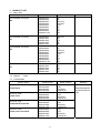
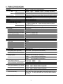
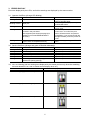
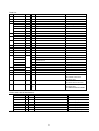
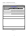
i350 / i355
i250 / i255
SIMPLIFIED MANUAL
1. PRODUCT LIST
2. PRODUCT SPECIFICATIONS
3. ERROR DISPLAY
4. SERVICE MODE (test print, EEPROM initialization, destination setting)
5. EXTERNAL VIEW / PARTS LIST
6. TROUBLESHOOTING FLOWCHART (main unit, print head)
7. SERVICE INFORMATION
APPENDIX 1: SHIPMENT INSPECTION PATTERN
APPENDIX 2: i350/i250 SERVICE TOOL
QY8-1389-000
Rev. 00
June 6, 2003
Canon Inc.
1
1. PRODUCT LIST
1-1. Main Units
Product name
Product code
Sales Territory
Canon Bubble Jet Printer
i350
8549A001AA
8549A002AA
8549A003AA
8549A004AA
8549A005AA
8549A006AA
8549A007AA
8549A009AA
8549A0011AA
US
CA
LAM LVT
LAM HVT
EUR
DE
FR
AU
GB
Canon Bubble Jet Printer
i355
8549A008AA
8549A010AA
8549A013AA
8549A014AA
8549A015AA
8550A001AA
8550A002AA
8550A003AA
8550A004AA
8550A005AA
8550A006AA
8550A007AA
8550A009AA
8550A0011AA
8550A008AA
8550A010AA
8550A013AA
8550A014AA
8550A015AA
ASA HVT
KR
TW
HK
CN
US
CA
LAM LVT
LAM HVT
EUR
DE
FR
AU
GB
ASA HVT
KR
TW
HK
CN
Canon Bubble Jet Printer
i250
Canon Bubble Jet Printer
i255
1-2. Options
Remarks
None
1-3. Consumables
Product name
Canon Ink Tank
BCI-24 Black
Canon Ink Tank
BCI-24 Color
Canon Ink Tank
BCI-24 Black Twin Pack
Canon Ink Tank
BCI-24 Color Twin Pack
Product code
Sales Territory
6881A001AA
6881A002AA
6881A003AA
6881A004AA
6882A001AA
6882A002AA
6882A003AA
6882A004AA
6881A008AA
6881A009AA
6881A010AA
6881A011AA
JPN
EUR
USA/CAN
ASIA/AUST
JPN
EUR
USA/CAN
ASIA/AUST
JPN
EUR
USA/CAN
ASIA/AUST
6882A008AA
6882A009AA
6882A010AA
6882A011AA
JPN
EUR
USA/CAN
ASIA/AUST
2
Remarks
Common with
S200/S200x/S300
/S330/i320/PIXUS
320i
2. PRODUCT SPECIFICATIONS
2-1. Printer Main Unit Specifications
Paper feeding method
Resolution
Printing speed
HQ
HS
CL
BK
CL
BK
Printing direction
Default mode print duty
Print width
Interface
Supported print head
No. of pages that can be printed
CL
BK
ASF
2,400dpi x 1,200dpi (at the highest resolution)
*Measured by new through-put pattern (LowEnd 2003)
i350/i355: 4 ppm
i250/i255: 3.5 ppm (CL through-put pattern)
11ppm
8 ppm
(BK through-put pattern)
11 ppm
9 ppm
(CL through-put pattern)
16 ppm
12 ppm
(BK through-put pattern)
Bi-directional / Uni-directional (automatically switched according to print data
and print mode)
i350/i250: 50% duty
i355/i255: 25% duty
203.2mm (8 inches)
USB (2.0) *Full Speed only
Service part: QY6-0044-000
CL: Approx. 170 pages, BK: Approx. 520 pages (SCID No.5 pattern,
default print mode)
BK: Approx. 300 pages (1500 character pattern, default print mode)
2
Max. 10mm (Approx. 100 pages of 75 g/m )
2
64 to 105 g/m
Plain paper
10mm or less
High resolution paper
10mm (Approx. 80 sheets) or less
Glossy photo paper
10 sheets or less
Professional photo paper / super photo A4/LTR/5x7 10 sheets or less
paper / matte photo paper
4x6
20 sheets or less
Transparency
30 sheets or less
Envelop
10 sheets or less
Professional photo card (PC-101)
S(4x6)
20 sheets or less
T-shirt transfer
1 sheet
Borderless printing
4x6 / 5x7 only
ASF stacking capacity
Paper weight
Detection function
Cover open
Presence of print head
Presence of ink tank
Paper out
Paper width
Waste ink full
Ink remaining amount
Head alignment
Acoustic noise level
Fine (glossy paper / high mode)
HQ
HS
Available
Available
Not available
Available
Not available
Available
Available (Detected by dot counting. Reset by user operation. Default on.)
Available (6 types)
Approx. 48 dB (Sound pressure level ISO9296)
Approx. 53 dB
Approx. 56 dB
Environmental requirements
During operation
Non-operation
Temperature
Humidity
Temperature
Humidity
5℃ to 35℃ (41 ゚ F to 95 ゚ F)
10% to 90%RH (no condensation)
0℃ to 40℃ (32゚F to 104゚F)
5% to 95%RH (no condensation)
Power supply
Input voltage / Frequency
Power consumption During printing
Stand-by status
AC 100∼127V 50/60Hz
AC 220∼240V 50/60Hz
Approx. 14 W
Approx. 1 W
(LV)
(HV)
External dimensions
With paper feed/delivery tray extended i350/i355: Approx. 385(W) X 422(D) X 317(H) mm
i250/i255: Approx. 385(W) X 224(D) X 268(H) mm
With paper feed/delivery tray set in
i350/i355: Approx. 385(W) X 195(D) X 165(H) mm
i250/i255: Approx. 385(W) X 195(D) X 165(H) mm
Weight
Approx. 2.4kg (excluding the print head and ink tanks)
Related standards
RFI, Electrical safety
FCC, IC, CE, C-Tick, VCCI, Taiwan EMC, Korean MIC, Gost-R, UL, CUL,
CB Report, GS, FT, Safety Standards, CCC, Korean EK, SASO, SPRING,
TUV (ARG)
*: Blue Angel pending
3
2-2. Product Life
3 years or 4,000 pages (2,500 pages of color printing and 1,500 pages of black printing), whichever
comes first
2-3. Print Head Specifications
Structure
4-color integrated type (ink tank separate type)
Print head
Bk:
C/M/Y:
Ink drop:
Ink colors
Bk (new pigment ink)
Cl: Y, M, C (high brilliance)
Ink tank
BCI-24 Bk, BCI-24 Color (common parts)
(Common with S300/S330/i320)
Weight
Approx. 60g (excluding ink tanks)
Supply method
Service part (excluding ink tanks)
Part number: QY6-0044-000 (common parts)
Common to the i320, however, not compatible with the S300/S330 series.
Print head life
4,000 pages (Same as the printer main unit, Cl: 2,500 pages, Bk: 1,500
pages of black printing
2 vertical lines, 320 nozzles
2 vertical lines in each color, 128 nozzles
Bk 30 pl, Col 5pl
Note: The print head can be physically installed in the old models, however, it is
incompatible with and cannot be used in the old models.
4
3. ERROR DIAPLAY
Errors are displayed by the LEDs, and ink low warnings are displayed by the status monitor.
3-1. Operator Call Error (Orange LED blinking)
LED Display
Content
Blinking 2 times
Paper out
Blinking 3 times
Paper jam
Blinking 4 times
Ink tank not installed
Blinking 5 times
Print head not installed or failure has
occurred in the print head.
(Not-supported print head (see page 5) is
installed or print head EEPROM data is
abnormal.)
Blinking 8 times
Waste ink full or platen waste ink full warning
(Approx. 95% of acceptable amount)
Corrective Action
Set paper, and press the RESUME
button to feed the paper.
Remove the jammed paper, and press
the RESUME button.
Re-install the ink tank, and close the
access cover.
Re-install the print head, and close the
access cover. Or confirm the print
head is “QY6-0044-000” and perform
re-installation. If not recovered with the
cartridge installed, power the printer off
and on.
Recoverable by pressing the RESUME
button.
3-2. Service Call Error (Orange and green LEDs blink alternately)
LED Display
Content
Corrective Action
Blinking 2 times Carriage error
Replace the printer as it has failed.
Blinking 6 times Internal temperature abnormal error
Replace the printer as it has failed.
Blinking 7 times Waste ink full or platen waste ink full error
Replace the printer as it has failed.
Blinking 8 times Abnormal temperature rise
Replace the printer as it has failed.
Blinking 9 times EEPROM error
Replace the printer as it has failed.
Blinking 10 times No cartridge detected excepting print head
Replace the printer as it has failed.
replacement (during printing)
3-3. Ink Low Warning (Ink low warnings are displayed by the status monitor only when the remaining
ink level detection is on, and no status monitor display when off.)
Content
Display by status monitor
Ink low warning 1 (approx. half level)
Ink low warning 2 (low remaining ink)
Ink low warning 3 (ink level unknown)
5
4. SERVICE MODE
To conduct the following functions, a host computer (Windows98/Me, Win2k/XP), printer driver and
service tool (QY9-0062/63) for the i350 are needed.
Function
Print head manual cleaning
Procedure
Select “Cleaning” from the printer driver utility.
Remarks
Cleaning time: Approx. 40 sec.
< For reference >
Head refreshing (deep cleaning) Select “Deep Cleaning” from the printer driver utility.
Paper feed roller cleaning
1. Remove the paper from the ASF.
2. Select “Feed Roller Cleaning“ from the printer driver Cleaning time: Approx. 2 min.
utility.
3. Following the instruction from the status monitor,
load 3 pages of plain paper in the ASF, and feed
them.
Test printing
1) Nozzle check pattern printing Select “Nozzle Check“ from the printer driver utility.
< For Reference >
Head alignment
Cleaning time: Approx. 70 sec.
Nozzle check pattern printing
1. Select “Print Head Alignment“ from the printer driver Significant misalignment can
be adjusted.
utility.
2. Select the optimal value using the printed head
position adjustment pattern.
Refer to Shipment inspection pattern*1 below.
2) Shipment pattern printing
- ROM version
- No. of pages fed
- Waste ink amount
EEPROM reset
Refer to EEPROM reset / Destination setting*3 below.
(Reset of waste ink counter etc.)
Refer to EEPROM reset / Destination setting*3 below.
Destination setting
(i350/i355/PIXUS 350i/
i250/i255)
Refer to Shipment inspection
pattern sample*2 below.
Host computer and service tool
are required.
Host computer and service tool
are required.
Host computer and service tool
are required.
*1 Shipment inspection pattern
a. With the printer powered on, install the print head (QY6-0044-000). (The green lamp lights.)
b. Load A4-sized paper.
c. Connect the printer to the computer, select “USB PORT” using the i350/i250 service tool (QY9-0062/0063). (Refer to
Appendix 2, i350/i250 Service Tool.)
d. Select “TEST PATTERN 1”. The printer starts printing the shipment inspection pattern.
2
* Shipment inspection pattern sample
EEPROM contents can be confirmed from the shipment inspection pattern printout. (top of the shipment inspection
pattern
Model name
Waste ink amount (%)
ROM Version
i350
P=V X.XX
Page=XXXX
D=XXXXX.X
PL=XXXX , HR=XXXX , GP=XXXX , CA=XXXX
SettingTime=XXXX / XX / XX XX:XX YY YY YY YY USB= (YYYYYY)
Installation time
No of pages fed:
Page: Total No. of pages fed
PL:
Plain paper
PR:
PR101, SP101, MP101
CA:
Postcard, Ink jet postcard, glossy
postcard
BL:
Borderless printing
(Counted separately from other
media)
*3 EEPROM reset / Destination setting
a. With the printer powered on, install the print head (QY6-0044-000). (The green lamp lights.)
b. Connect the printer to the computer, select “USB PORT” using the i350/i250 service tool (QY9-0062/0063). (Refer to
Appendix 2, i350/i250 Service Tool.)
c. <Destination setting>
Destination can be set by clicking each model name in “SET DESTINATION.”
Setting can be changed from the i350 to the i250/i255 (vice versa). Confirm the model name by clicking “GET
DEVICE ID” after setting change. (If incorrect, it can be changed before turning the unit OFF/ON.)
<EEPROM reset>
The EEPROM is reset after the shipment inspection pattern printing when ”EEPROM CLEAR” is checked.
6
5.
EXTERNAL VIEW / PARTS LIST
1. External parts, Power supply unit, Logic Board Ass’y
2. Print Unit
7
Parts List
Key
Part Number
Rank
Q'ty
Description
Remark
QY6-0044-000
K
1
PRINT HEAD
i350/i355/PIXUS350i, i250/i255
1
QA4-1285-000
J
1
SCREW, PAN HEAD SELF-TAPPING, M3X6
i350/PIXUS 350i/i355
2
QC1-1701-000
J
1
EXTENSION OUTPUT TRAY
i350/PIXUS 350i/i355
3
QC1-1707-000
J
1
FRONT COVER
i350
4
5
6
QC1-1708-000
J
1
FRONT COVER
PIXUS 350i (J)
QC1-1715-000
J
1
FRONT COVER
i355 (CHN/ASIA/TWN/KRN)
i250
QC1-1709-000
J
1
FRONT COVER
QC1-1716-000
J
1
FRONT COVER
i255 (CHN/ASIA/TWN/KRN)
QC1-1703-000
J
1
SIDE COVER L
i350/PIXUS 350i/i355
QC1-1705-000
J
1
SIDE COVER L
i250/i255
QC1-1704-000
J
1
SIDE COVER R
i350/PIXUS 350i/i355
QC1-1706-000
J
1
SIDE COVER R
i250/i255
QA4-1283-000
J
1
PAPER SUPPORT
i350/PIXUS 350i/i355
QC1-1699-000
J
1
PAPER SUPPORT
i250/i255
7
QC1-1700-000
J
1
EXTENSION PAPER SUPPORT
i350/PIXUS 350i/i355
8
QG4-0331-000
J
1
UPPER COVER UNIT, WITH BUTTON
9
QA4-1275-000
J
1
COVER, I/F
10
QM2-0497-000
M
1
LOGIC BOARD ASS’Y
11
QA4-1268-000
C
1
FILM, TIMING SLIT STRIP
12
QK1-0058-000
D
1
AC ADAPTER: 100/127V 50/60HZ
LV (USA,CANADA,JAPAN)
QK1-0060-000
1
AC ADAPTER: 220/240V 50/60HZ
HV (EUR)
QK1-0127-000
1
QK1-0064-000
1
AC ADAPTER: 100/127V 50/60HZ, TWN
LV (TWN)
1
AC ADAPTER: 220/240V 50/60HZ, KRN
HV (KRN)
1
SPRING, TIMING SLIT STRIP FILM
i350/PIXUS 350i/i355
1
SPRING, TIMING SLIT STRIP FILM
i250/i255
QK1-0062-000
13
QC1-1695-000
C
QC1-1696-000
AC ADAPTER: 220/240V 50/60HZ,
CHN/ASIA/AUS
14
WT2-5694-000
F
1
CLAMP, CABLE
15
QM2-0476-000
K
1
PRINT UNIT
S1
XA9-1493-000
G
9
SCREW, TP M3X8
HV (CHN/ASIA/AUS)
FOR AC ADAPTER
FOR UPPER CASE UNIT
FOR PRINT UNIT
S2
XB6-7300-605
G
4
SCREW, TP M3X6 MM
FOR LOGIC BOARD ASS’Y
S3
XB1-2300-405
G
2
SCREW, M3X4
i350/PIXUS 350i/i355 (i250/i255)
FOR PRINT UNIT/LF MOTOR
(1)
FOR PRINT UNIT
FOR TIMINGSLITSTRIPFILMSPRING
Power cords are as listed below.
WT3-5122-000
E
1
CORD, POWER
100V-120V (J)
WT3-5131-000
E
1
CORD, POWER
100V-120V
WT3-5132-000
E
1
CORD, POWER
220V-240V
WT3-5133-000
E
1
CORD, POWER
220V-240V (AUS)
WT3-5165-000
E
1
CORD, POWER
220V-240V (AR)
WT3-5135-000
E
1
CORD, POWER
250V (CN)
WT3-5137-000
E
1
CORD, POWER
220V-240V (GB, HK)
WT3-5158-000
E
1
CORD, POWER
220V-240V (KR)
WT3-5159-000
E
1
CORD, POWER
220V-240V (LAM-LV)
8
6. TROUBLESHOOTING FLOWCHART
6-1. Printer Main Unit Troubleshooting Flowchart (how to confirm printer operation at refurbishment)
Power ON
Error displayed?
Yes
No
Open access cover,
and install head
Error displayed?
Yes
No
Connect to computer
Shipment inspection
pattern printing
Correct?
< Shipment inspection pattern check items>
(Refer to the attached print sample.)
*Refer to 4. SERVICE MODE
regarding printing method.
1. Ink non-ejection:
2. Top margin:
3. Line:
4. Gray area:
No
Yes
Yes
Outside of paper
Not connected
White lines / uneven density
Replace head and print
shipment inspection pattern
Correct?
No
Yes
Waste ink counter
less than 7%?
No
Yes
Normal
Defective
< Note for normal printer refurbishment >
At refurbishment, install the print head, connect the AC plug while holding down the POWER button,
and after the LED lights green press the RESUME button twice and release it while pressing the
POWER button. (The LED lights in orange first, and then green whenever the RESUME button is
pressed.) With this condition, be sure to reset the EEPROM in accordance with 4. SERVICE MODE, the
EEPROM reset procedure. Since the printer becomes in shipping mode (carriage in replacing position,
raised paper lifting plate) by powering off with POWER button, remove the print head, unplug the power
cord immediately, and do not print afterwards.
9
NG
NG
NG
NG
6-2. Print Head Troubleshooting Flowchart (print head operation confirmation)
Connect to computer
*Refer to 4. SERVICE MODE
regarding printing method.
Nozzle check pattern
printing
Correct?
Yes
No
Head cleaning
*Refer to 4. SERVICE MODE
regarding printing method.
Nozzle check pattern
printing
Correct?
Yes
No
Head refreshing
*Refer to 4. SERVICE MODE
regarding printing method.
Nozzle check pattern
printing
Correct?
Yes
No
*Refer to 4. SERVICE MODE
regarding printing method.
Head refreshing
Nozzle check pattern
printing
Correct?
Yes
No
Replace ink tanks
Nozzle check pattern
printing
Correct?
Yes
No
Normal
Defective
10
7. SERVICE INFORMATION
7-1. Print Unit Replacement (Asia only)
When the print unit is exchanged, re-affix a Serial number label affixed to the Chassis.
11
7-2. Product Technical Information
1) FAQ (Problems specific to the i350/i355, i250/i255 and corrective actions)
No. Rank* Function
Phenomenon
Cause
The user may not have removed the
1
A Installation Carriage error (LED
packing material at unpacking and
blinks alternately in
orange and green twice). installation.
Although a caution sheet is packaged
together with the printer, the user may not
have noticed it.
Note: Even if the packing material remains,
no parts are damaged.
2
A
Ink tank installation error Since the user did not fully seat the ink tank
completely at unpacking, installation, and
(orange LED blinks 4
ink tank replacement, the ink tank contacts
times.)
the main case.
3
B
Paper not feeding when
lots of paper/media is
feedability loaded. (PC101/PR101)
4
B
Multi-feeding.
5
B
Envelope not feeding.
6
B
Envelope jam at feeding
7
B
Paper jam.
Paper
Corrective action
Remove the packing
material fixing the
carriage.
Possible Call / Claim
-LED blinks alternately in orange
and green, twice (carriage error)
Open the Access Cover,
and install the ink tank
properly.
-Orange LED blinks 4 times (ink
tank installation error) (As this
occurs at printer installation, the
user cannot recognize the error.)
When the paper is curled and many sheets 1. Decrease the number
of pages loaded in the
are loaded, the loaded page limit level in
the ASF creates friction at paper feeding. ASF.
2. Flatten curled paper.
In the high temperature and high humidity 1. Set the paper in the
ASF
environment, the frictional force between
the front and back sides of paper becomes 2. In case of PR101, set
the paper sheet by sheet
high, and sheets stick to each other,
in the ASF.
contributing to multi-feeding.
The paper feed roller slips on the paper at 1. Perform roller cleaning
from the printer driver.
paper feeding.
2. Decrease the number
Note: Depending on the paper lots. This
of envelopes loaded in
phenomenon may occur in DL envelope.
the ASF.
3. Flatten the paper (with
a pen).
1. Perform roller cleaning
When the paper is fed by the
slightly-slippery paper feed roller, the flap is from the printer driver.
2. Decrease the number
caught in the return position of the claw.
of envelopes loaded in
the ASF.
1. Remove the jammed
As the LF Roller slips on the paper, the
paper from the paper
paper is not fed, causing the jam error at
pick-up side.
paper ejecting.
12
-Paper out error
-Paper cannot be fed
-Cannot print
-Multiple pages of paper are fed
-Paper is delivered without
printing
-Paper out error
-Paper cannot be fed
-Cannot print
-Paper jam error
-Paper cannot be fed
-Cannot print
-Paper jam error
-Paper cannot be fed
-Cannot print
8
B
9
B
Smearing on the
backside of paper, or
smear on address side of
postcards.
10
C
11
C
When the paper end comes off the pinch
Horizontal lines and
roller, printing is performed without the
uneven print density at
the trailing edge of paper paper being held, preventing the ink drops
from being ejected in the correct positions,
resulting in unevenness.
Note: The problem is more severe than
that of the i320/PIXUS 320i.
As the print media slightly slips while being
Horizontal lines and
uneven print density due fed by the LF roller, printed areas overlap,
causing the problem.
to LF roller feeding at
small pitch.
Image
quality
Smearing on printed side. The edge of paper rises due when paper is
curled, causing the print head to rub
against the printed surface of paper,
resulting in smearing.
When borderless printing is conducted
continuously, ink mist attaches to the ribs
on the platen, and is transferred to the
backside of the following paper.
1. Correct the paper curl.
2. Recommend the user
to conduct printing in the
print quality assurance
area. (In the i350/i355,
i250/i255, the
head-to-paper distance
cannot be changed.)
Note: In borderless
printing (to 4X6/5X7),
correct the paper curl.
Clean the ribs on the
platen with cotton
swabs/buds.
Recommend printing in
the print quality
assurance area.
Change the print quality
from standard to high
mode.
-Smear on the printed side of
paper
-Cannot print properly
-Paper edge crease
<When printing address side of
postcards>
-Smears on the address side
<When printing correct side
(message side) of paper>
-Smears on the backside
-Cannot print to the bottom edge
of paper
-Lines and uneven print density
appear in the trailing edge of
paper
-Cannot print properly
-Lines and uneven print density
(on flesh tones and background)
-Cannot print properly
*Rank
A: The phenomenon may occur at a relatively high occurrence ratio. (Caution needed)
B: The phenomenon may occur in specific conditions, however the occurrence ratio is expected to be considerably low in the actual usage.
C: As the phenomenon is unlikely to be recognized by general users, it is expected to cause no claims from the users.
13
2) New functions
1. Borderless printing (4”x6”, 5”x7” size only)
The i350/i355 support borderless printing only for 4”x6”, 5”x7” size paper. Borderless printing is not
supported with other paper sizes (A4, LTR, etc.) and with the i250/i255.
< Possible problems with this function >
- Smearing on the message side of postcards, and smearing on the address side in continuous borderless
printing
-> Clean the ribs on the platen
- Smearing on the backside of paper in continuous borderless printing
-> Clean the ribs on the platen
- Ink mist on the platen
-> Clean the ribs on the platen
2. No paper selection lever
The printer does not need adjustment via a paper selection lever. (Adjustment of the head-to-paper
distance when printing envelopes is not necessary.)
< Possible problems with this function >
- The head rubs against the paper when paper curl is curled.
-> Flatten curled paper. (To less than 3mm)
-> In print modes other than borderless printing, conduct printing in the print quality assurance area of
the top and bottom edges. (Top margin: 28mm; bottom margin: 26.5mm)
3. Quiet mode
The printer has a quiet mode function.
Compared with the normal mode,
Acoustic noise level:
Slightly lower. (HQ, normal: Approx. 50dB, Quiet: Approx. 49dB)
Audible overtone level:
Sound quality changes, and sound becomes quieter.
Print speed:
Slows. (Bk printing in HQ/HS mode using an acoustic noise
measurement pattern: Approx.1.3 times)
3) Other functions
1. Remaining ink level detection function
The printer has a function to detect the remaining ink level. (Default setting: ON)
Detection method: Dot counting (Counted for each Bk/Cl ink tank).
Cl tank: The remaining ink level is detected by total counted dot values of 3 color
ink tanks.
Display method:
Displayed on the status monitor (at 3 levels shown below for each Bk/Cl ink tank)
Level 1: Half level of remaining ink level (Approx. 40% of ink remaining)
Level 2: Indication of “!” mark (Approx. 10% of ink remaining)
Lever 3: Indication of “?” mark (Remaining ink level is unknown)
*Remaining ink detection function displays the status only, and does not cause
errors.
Accuracy:
The margin of error of detection accuracy is +/-10% in normal printing.
*The margin of error is likely to be large in the following specific print patterns:
When printing continuously using any one of the CMY ink tanks
-> As the remaining ink level is calculated by total counted dot values of 3 color
ink tanks, if any of the C/M/Y inks is heavily consumed, the margin of error for
remaining ink increases.
When performing continuous Bk solid printing
-> With continuous printing, ink flow from the tank to the ink chamber can be
interrupted, after which ink remains unused in the tank.
Reset procedure: Perform the following operations from the printer driver utility.
1. Set the indication of the remaining ink level in “Low Ink Warning Setting”.
2. Reset the ink counter in “Ink Counter Reset”.
Note: Be sure to reset the ink counter from the printer driver utility after replacing
ink tanks.
14
< Possible problems with this function >
- Due to user error, the actual remaining ink level does not match the indicated remaining ink level,
resulting in “ink out”, etc.
User error: Forgetting to reset ink counter / ink counter reset other than when replacing ink tanks.
- Due to the specific print pattern, the actual remaining ink level does not match the indicated remaining ink
level, resulting in “ink out”.
Specific print pattern: Continuous printing using any one of the CMY ink tanks / continuous Bk solid
printing, etc.
2. Head refreshing
The printer has a head refreshing function.
Head refreshing: This is a deep cleaning function in order to resolve print failure due to ink clogging
the print head. (The black ink is pigment-based, and clogs easier than the current
dye-based ink.)
*Perform from the printer driver utility.
< Possible problems with this function >
- Excessive ink consumption when conducting head refreshing repeatedly. (The amount of ink used is
approx. 10 to 15 times the normal manual cleaning amount.)
< Reference >
Cleaning types, amount of ink used and time required *Bk and Cl ink suction is simultaneously
performed.
Cleaning type
Amount of ink used
Time required
Manual cleaning
Bk: Approx. 0.15g
Dot count cleaning
Approx. 40 sec.
Cl: Approx. 0.15g
Timer cleaning (24 hours to 2 weeks)
Head replacement
Bk: Approx. 0.30g
Ink tank replacement
Approx. 45 sec.
Cl: Approx. 0.30g
Cleaning when the head is not capped at printer power on
Cleaning on arrival at user
Bk: Approx. 0.45g
Approx. 60 sec.
Timer cleaning (2 weeks to 3 months)
Cl: Approx. 0.45g
Head refreshing
Bk: Approx. 1.5g
Approx. 70 sec.
Timer cleaning (3 months or more)
Cl: Approx. 2.2g
3. Head alignment
The printer has a head alignment function (head position adjustment function). (The adjustment is needed
at the initial set-up by the user.)
Head alignment:
This is a function to correct the displacements between the nozzle lines of the
print head, and incorrect print position at bi-directional printing. The adjustment is
conducted using the printed head position adjustment pattern.
A: Head alignment between black nozzle lines
B: Head alignment between cyan nozzle lines
C: Head alignment between magenta nozzle lines
D: Head alignment in bi-directional black printing
E: Head alignment in bi-directional color printing
F: Head alignment between black and color printing
*Perform from the printer driver utility.
(At initial set-up by the user, notice to perform the head alignment is
displayed in the status monitor.)
15
APPENDIX 1:
SHIPMENT INSPECTION PATTERN 1
Check item 1 (Ink non-ejection): Total area of the sample below
Check item 2 (Top margin)
Print EEPROM information
-> Refer to 4. SERVICE MODE for details.
Bk nozzle check pattern
C nozzle check pattern
M nozzle check pattern
Check item 3 (Vertical Lines)
Check item 4 (Gray area)
Paper size: A4
16
Y nozzle check pattern
APPENDIX 2:
i350/i250 SERVICE TOOL
< How to use the i350/i250 Service Tool (QY6-0062/0063) >
Usage:
Shipment inspection pattern printing
Destination setting in EPROM
EEPROM reset
Supported OS:
Windows 98/Me (J/E version) :
QY9-0062
Windows 2000/XP (J/E version) : QY9-0063
Distribution method: Provided by SSIS (Download “i350/i250 Service Tool” from software download in
SSIS.)
< Usage procedures >
1. Unzip the “i350tool_Win98V100.EXE/i350tool_Win2kV100.EXE” file. (Automatically unzipped by
double-click)
2. Open the “i350tool_Win98V100.EXE/i350tool_Win2kV100.EXE” folder created after unzipping.
3. Open the “GeneralTool.exe” file.
A
B
F
C
D
E
A
B
C
4.
Select the connected USB PORT No. from “USB PORT” (A).
< How to print the shipment inspection pattern >
Select “TEST PATTERN 1” (B), and the shipment inspection pattern 1 will be printed.
(Refer to APPENDIX 1, SHIPMENT INSPECTION PATTERN.)
< How to set the destination >
17
1.
2.
Select either of “1” or “2” from “SET DESTINATION” (C), and the destination will be set.
“PIXUS 350i”:
Japan
“i355/i255”:
Asia
“i350/i250”:
Other than the above area
Confirm that the model name is indicated in the (E) area when clicking “DEVICE ID” (D).
Or, confirm the model name by performing the shipment pattern printing.
< EEPROM reset >
When printing the shipment pattern after the “EEPROM CLEAR” (F) check box is marked, the EEPROM
will be reset.
18