1
250.1
power
®
250.2
power
punch
new
chrome
heatsink
®
car audio
competition Power amplifiers
Operation & Installation
®
for
fanatics
Dear Customer,
Congratulations on your purchase of the world's finest brand of car audio amplifiers. At Rockford Fosgate we
are fanatics about musical reproduction at its best, and we are pleased you chose our product. Through years
of engineering expertise, hand craftsmanship and critical testing procedures, we have created a wide range of
products that reproduce music with all the clarity and richness you deserve.
For maximum performance we recommend you have your new Rockford Fosgate product installed by an
Authorized Rockford Fosgate Dealer, as we provide specialized training through Rockford Technical Training
Institute (RTTI). Please read your warranty and retain your receipt and original carton for possible future use.
Great product and competent installations are only a piece of the puzzle when it comes to your system. Make
sure that your installer is using 100% authentic installation accessories from Connecting Punch in your
installation. Connecting Punch has everything from RCA cables and speaker wire to Power line and battery
connectors. Insist on it! After all, your new system deserves nothing but the best.
To add the finishing touch to your new fanatic image order your Rockford Fosgate wearables, which include
everything from T-shirts and jackets to hats and sunglasses.
To get a free brochure on Rockford Fosgate products and Rockford wearables, please call 602-967-3565 or FAX
602-967-8132. For International orders, FAX +001-1-602-967-8132 or call +001-1-602-967-3565.
PRACTICE SAFE SOUND™
CONTINUOUS EXPOSURE TO SOUND PRESSURE LEVELS OVER 100dB MAY CAUSE PERMANENT HEARING LOSS.
HIGH
POWERED AUTOSOUND SYSTEMS MAY PRODUCE SOUND PRESSURE LEVELS WELL OVER
130dB. USE
COMMON SENSE AND PRACTICE SAFE SOUND.
If, after reading your manual, you still have questions regarding this product, we recommend that you see your Rockford Fosgate
dealer. If you need further assistance, you can call us direct at 1-800-669-9899. Be sure to have your serial number, model number
and date of purchase available when you call.
The serial number can be found on the outside of the box. Please record it in the space provided below as your permanent record.
This will serve as verification of your factory warranty and may become useful in recovering your amplifier if it is ever stolen.
Serial Number: _____________________________________________
Model Number: ____________________________________________
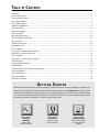
T ABLE
OF
C ONTENTS
Introduction ................................................................................................................................................................. 1
Punch Accessory Pack ................................................................................................................................................. 1
Technical Design Features ............................................................................................................................................. 2
250.2 Design Features ................................................................................................................................................. 5
250.1 Design Features ................................................................................................................................................. 7
Installation Considerations ............................................................................................................................................ 9
Mounting Locations .................................................................................................................................................... 10
Battery and Charging ................................................................................................................................................. 10
Wiring the System ...................................................................................................................................................... 11
Using Passive Crossovers ............................................................................................................................................ 12
Table of Crossover Components ................................................................................................................................... 13
Using the XCard ......................................................................................................................................................... 14
Customizing the XCard ............................................................................................................................................... 14
XCard Resistor Chart ................................................................................................................................................... 15
250.2 Installation ...................................................................................................................................................... 16
Using the 250.2 Internal Switching Network .................................................................................................................. 19
Using the 250.2 Balanced Line Inputs .......................................................................................................................... 24
250.1 Installation ...................................................................................................................................................... 26
Using the 250.1 Internal Switching Network .................................................................................................................. 31
System Diagrams ....................................................................................................................................................... 34
Rockford Fosgate Accessories ...................................................................................................................................... 38
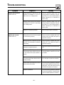
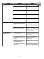
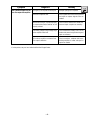
Troubleshooting ......................................................................................................................................................... 40
Autosound 2000’s Quick Check for Troubleshooting ....................................................................................................... 43
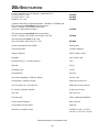
250.2 Specifications ................................................................................................................................................... 46
250.1 Specifications .................................................................................................................................................. 47
Warranty Information ................................................................................................................................................. 48
International Information ............................................................................................................................................. 49
G E T T I N G S TA R T E D
Welcome to Rockford Fosgate! This manual is designed to provide information for the owner, salesperson and installer. For
those of you who want quick information on how to install this product please turn to the Installation section of this manual
or refer to the icons listed below. Other information can be located by using the Table of Contents. We, at Rockford Fosgate,
have worked very hard to make sure all the information in this manual is current. But, as we are constantly finding new ways
to improve our product, this information is subject to change without notice.
a
d
v
a
n
c
e
d
O
p
e
r
a
t
i
o
n
Sections marked
ADVANCED
OPERATION
include in-depth
technical information
®
®
I
N
S
T
A
L
L
A
T
I
O
N
Sections marked
INSTALLATION
include “slam dunk”
wiring connections
TROUBLE-S
H
O
O
T
I
N
G
Sections marked
TROUBLESHOOTING
include recommendations
for curing installation
problems
INTRODUCTION TO 250 SERIES
The “250 Series” Power amplifiers represent the best Rockford Fosgate has to offer! Our engineers devised technical features
which would be considered overkill by other audio manufacturers, but not at Rockford Fosgate! Trans•nova, DIAMOND and
TOPAZ, exclusively designed by Rockford, are just a few of these features which are described in the Technical Design
Features section of this manual.
The 250.2 is a two-channel amplifier which is optimized to drive 2Ω stereo and 4Ω bridged loads. The 250.1 is a single
channel amplifier optimized to drive a 2Ω (single amp) or a 4Ω bridged load (pair of amps bridged to a single load).
The “250 series” use Rockford's innovative technologies for awesome sound quality, reliable performance and high output
power into low impedances. This can be beneficial for serious competition vehicles.
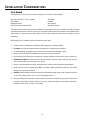
P UNCH A MPLIFIER A CCESSORY P ACK
The accessory pack shipped with the “250 series” Power amplifiers include the mounting hardware necessary to secure
the ampliifer to the vehicle and to attach the end caps to the amplifier.
Punch Power 250.2
Punch Power 250.1
Installation & Operation Manual
Punch Verification Certificate
(4) Amplifier mounting screws (#8 x 3⁄4" phillips)
(8) Speaker & power connector screws (3/32" allen)
(4) End cap mounting screws (9/64" allen)
(1) Allen wrench 3/32"
(1) Allen wrench 9/64"
Installation & Operation Manual
Punch Verification Certificate
(4) Amplifier mounting screws (#8 x 3⁄4" phillips)
(6) Speaker & power connector screws (3/32" allen)
(4) End cap mounting screws (9/64" allen)
(1) Allen wrench 3/32"
(1) Allen wrench 9/64"
–1–
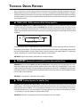
T ECHNICAL D ESIGN F EATURES
Many of the solutions to common design problems encountered by Rockford Fosgate engineers created entire new circuit
designs as well as new ways to construct the Punch 250.2 and 250.1 Power Amplifiers. In our flagship amplifiers, no expense
was spared in design and construction from the unique circuitry design to the manufacturing process that has proven to be
the industry reference for many years. Described below are just some of the accomplishments achieved by our engineering
and manufacturing staff.
◆ trans•nova
(TRANSconductance NOdal Voltage Amplifier)
The trans•nova (TRANS conductance NOdal Voltage Amplifier) is a patented circuit (U.S. Patent 4,467,288) that allows
the audio signal to pass through the amplifier at low voltage. Each amplifier channel utilizes its own “fully floating” power
supply and is configured to increase power gain. The increase in power gain allows the drive stage to operate at a lower
voltage. A low voltage drive stage is the same principle used in high quality preamplifiers to produce high linearity and wide
bandwidth.
E-I
I-E
trans•nova circuitry
The resulting design utilizes an output stage with a simpler gain structure and a shorter total signal path than conventional
high voltage (bi-polar) designs. The number of stages is reduced from five or more to three. The output stage is further refined
into a trans-impedance stage (current to voltage converter) to achieve a short loop (fast) negative feedback. The output stage
is driven cooperatively by a transconductance stage (voltage to current converter).
THE RESULT: Superior sound quality, greater efficiency and higher reliability.
◆ DIAMOND (Dynamically Invariant AMPlification Optimized Nodal Drive)
DIAMOND (Dynamically Invariant AMplification Optimized Nodal Drive - patent pending) is an important advance in circuit
design which reduces high frequency distortion. Amplifiers which utilize a large array of output MOSFETs cause a high
capacitive load on the driver stage. This load can make the high frequencies sound harsh. The DIAMOND circuit eliminates
high frequency distortion by allowing the driver to operate with 20dB or more of current headroom, whereas traditional drivers
have only 6dB of current headroom.
THE RESULT: Lower distortion and greater inherent stability.
◆ TOPAZ (Tracking Operation Pre-Amplifier Zone)
The TOPAZ (Tracking Operation Pre-Amplifier Zone) circuitry solves ground loop noise problems common to automotive
amplifier design. This innovative new development allows vastly improved isolation of the input signal grounds from the
power supply ground of the amplifier. This is accomplished by allowing the source unit to control the potential “environment”
of the entire input structure or “zone” of the amplifier. This process improves the noise rejection of the amplifier by 30-40dB
– an astounding 20-100 times better than amplifiers without TOPAZ.
THE RESULT: Elimination of troublesome ground loop noise between source and amplifier.
–2–
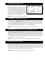
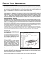
◆ DSM (Discrete Surface Mount Technology)
The DSM (Discrete Surface Mount) manufacturing process combines the advantages of both discrete components and
integrated circuitry. Rockford Fosgate is the only American amplifier manufacturer to have invested millions into this process.
DSM components differ from conventional discrete components in different ways. They are more compact, more rugged,
and they efficiently dissipate generated heat. Using them wherever appropriate allows the advantages associated with discrete
circuitry to be retained while also providing room for both highly advanced processing features and generous PC board
copper paths where needed. Their short lead-out structures allow maximum audio performance and highest signal-to-noise
ratios to be obtained in amplifiers of desirable package size without resorting to “amplifier-on-a-chip” shortcuts. These
advantages are shown below in Figure 1.
Component
Figure 1
Solder
Solder
PC Board
PC Board
Thru-Hole
Surface Mount
THE RESULT: Less connections, improved reliability, shorter signal paths, superior signal-to-noise ratio and awesome sonic
performance.
◆ XCard (Internal Crossover)
The Power amplifiers utilize internal active crossovers. These crossovers have many performance advantages such as using
discrete components for exact frequency adjustments which are far superior to potentiometers. Additionally, the XCard can
be configured for high-pass, low-pass and full range operation. With slight modification, many crossover frequencies and
slope configurations can be achieved.
THE RESULT: Increased system design flexibility with a precise electronic crossover without the limitations of conventional
potentiometer designs.
◆ Stereo Pass-Thru
The Pass-Thru output provides a convenient source for daisy-chaining an additional amplifier without the need for extra RCA
cables or “Y” adapters. The 250.1 Pass-Thru provides constant Full Range stereo output. The 250.2 has the ability to provide
constant Full Range stereo output as well as distribute one of its internal XCards to the Pass-Thru for a dedicated High-Pass
or Low-Pass output.
THE RESULT: Convenient signal level output for adding extra amplifiers.
–3–
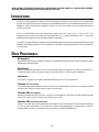
◆ Balanced Line Inputs (250.2)
Using the Balanced Line Inputs provides the last word in achievable rejection of noise induced in the cable between the source
and the amplifier. The differential input circuitry (Figure 2) used
in the balanced input system rejects whatever signals are
common to both of the shielded, twisted-pair conductors. Balanced line is universal in concert installations where the stage
and mixing consoles are hundreds of feet apart. Long signal
cables and electrically-noisy environments make signal integrity
and noise rejection an extremely difficult challenge.
Figure 2
RCA Input
Center
Conductor
Differential
Input
Outer
Shield
Differential inputs only amplify the difference between two conductors.
Note: the noise spikes appear on both the center conductor and the outer
shield and therefore are not amplified.
THE RESULT: Quiet transmission of audio from source to amplifier.
◆ NOMAD (NOn-Multiplying Advanced Decision)
The Power amplifiers use an analog computer process to absolutely maximize safe output power under all operating
conditions. The innovative NOMAD (NOn-Multiplying Advanced Decision) system is the most sophisticated version of this
technique ever used, bringing previously unavailable levels of accuracy, stability, temperature immunity and reliability to
this critical process. NOMAD makes advanced decisions based on device voltages to precisely control the awesome levels
of current available in the output MOSFETs to safe values – but only when absolutely needed.
THE RESULT: Extremely fast protection system that always protects the amplifier and never degrades the sound.
◆ MOSFET Devices
(Metal Oxide Semiconductor Field Effect Transistor)
Rockford Fosgate is one of the few manufacturers in any of the sound communities to utilize MOSFET devices in both the power
supply and the output stages. MOSFET (Metal Oxide Semiconductor Field Effect Transistor) devices offer several important
inherent advantages over the 30 year old technology of bi-polar design. These advantages include: thermal stability,
switching speed, ultra low output impedance and wider bandwidth linearity. In addition, MOSFET and vacuum tubes share
many important operating characteristics. However, the MOSFET device is much faster, wider in bandwidth, measurably
lower in distortion and far more linear than vacuum tubes.
THE RESULT: Operational characteristics of vacuum tubes without the performance limitations of tube design.
◆ ITS
(Increased Thermal Stability)
The ITS (Increased Thermal Stability) Power Supply design is new in Rockford Fosgate amplifiers. A major problem
associated with any amplifier design is how to get rid of the heat generated by its circuitry. Clearly, it is highly desirable to
minimize the amount of heat generated in the first place. The “250 series” Power amplifiers employ a new toroidal power
transformer design in which the high current input leads are carried directly to the switching power MOSFETs. This both
minimizes PC board heating and takes advantage of natural air cooling of these leads.
THE RESULT: Maximizes power supply efficiency by eliminating unnecessary heat generation.
–4–
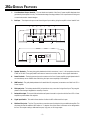
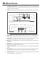
250.2 D E S I G N F E AT U R E S
1.
Cast Aluminum Chrome Heatsink – The cast aluminum heatsink of the Punch Power amplifier dissipates heat
generated by the amplifier's circuitry. The inherent advantage of casting provides a 30% improvement of cooling over
conventional extrusion heatsink designs.
2.
End Caps – The unique end caps conceal the wiring and input cables, giving the amplifier a clean “stealth” look.
3
13
8
Unbal.
Speaker
+ L –
0°-180°
6
L (Mono)
7
Gain
10
3
R
Bal.
PassThru
12
Bal.
Input
L
EZ - 180° - 0°
Bridged
R
Speaker
+ R –
Gain
9
10
Power
REM
16
5
Dual B+
Dual GND
4
4
3.
Speaker Terminals – The heavy duty, gold-plated terminal block connectors (+ and –) will accept wire sizes from
8 AWG to 18 AWG. These gold-plated connectors are immune to corrosion that can cause signal deterioration.
4.
Power Terminals – The dual power and ground connectors on the Punch Power amplifier are gold-plated and will
accommodate up to two 8 AWG wires maximizing the input current capability of the amplifier.
5.
REM Terminal – This gold-plated spade terminal is used for the AP (auto power) or remote turn on of the Punch 250.2
Power amplifier.
6.
RCA Input Jacks – The industry standard RCA jack provides an easy connection for signal level input. They are goldplated to resist the signal degradation caused by corrosion.
7.
Balanced Line Input– This input will allow the balanced inputs to be used in conjunction with the Punch 250.2 Power
amplifier to provide better noise rejection.
8.
Signal Input Switch – This switch allows selection of either the RCA or Balanced Line inputs.
9.
RCA Pass-Thru Jacks – The Pass-Thru provides a convenient source for daisychaining an additional amplifier. This
eliminates the need for additional RCA cables or “Y” adapters. One of the internal crossovers can be designated to
the Pass Thru output creating a dedicated low-pass, high-pass, or full range output.
–5–
10. Input Sensitivity Controls – The input level controls are preset to match the output of most source units. They can be
adjusted to match output levels from a variety of source units.
11. Internal Crossovers – These built-in crossover cards are configurable for a multitude of operating frequencies. The
orientation of the card in its socket determines its function of high-pass, low-pass or full range operation.
12. E-Z Bridge Switch / 0°-180° Phase Switch – This dual purpose switch enables you to E-Z bridge the amplifier or invert
the signal phase of the right channel.
13. Phase Switch – This switch enables you to easily invert the phase of the left channel without having to disconnect the
speaker wires.
14. Crossover Switching – These internal switches allow the crossover to be distributed to the amplifier and Pass-Thru
in many different configurations.
15. Audiophile Bypass – One of the crossover switching configurations allows the internal crossover circuit to be bypassed,
maintaining Audiophile sound quality due to a shorter signal path.
16. LED Power Indicator – The LED gives a visual indication of the status of the amplifier, lighting when the unit is turned on.
®
250.2 AM PL IF IE R
P
E
R
2 into 4 Ohms
125 Watts X
20kHz
+ N from 200.05% THD
with less than
2 into 2 Ohms
225 Watts X
20kHz
+ N from 200.10% THD
with less than
ns
Pass Thru
Amplifier
W
High-Pass
HP
XCard Optio
O
LP
XC ar d 2
XCa rd 2
®
Amplifier
XCa rd 2
XCa rd 1
Not Used
250.2 can be
te: The Punch
your
*Bridging No
tions. Refer to
ny configura
will
bridged in ma
which mode
ine
l to determ
nua
ma
's
.
owner
your system
in
t
bes
rk
wo
14
&
15
11
Byp ass
Not Used
XCa rd 2
Full Range
FULL
XCa rd 1
Low-Pass
HP
Au dio phi le
IO N
XC ar d 1
Amplifier
CO RP OR AT
RO CK FO RD
E US A
MA DE IN TH
LP
XCa rd 1
Byp ass
Au dio phi le
Pass Thru
Am p On ly
Not Used
XCa rd 1
XCa rd 2
–6–
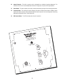
250.1 D ESIGN F EATURES
1.
Cast Aluminum Chrome Heatsink – The cast aluminum heatsink of the Punch Power amplifier dissipates heat
generated by the amplifier's circuitry. The inherent advantage of casting provides a 30% improvement of cooling over
conventional extrusion heatsink designs.
2.
End Caps – The unique end caps conceal the wiring and input cables, giving the amplifier a clean “stealth” look.
9
6
L (Mono)
R
13
12
7
Power
X-Over
24dB/12dB/0dB
Gain
Speaker
+ L –
L Pass-Thru
3
11
R Pass-Thru
0°-180°
L+R/L
(Mono)
8
REM
Dual B+
Dual GND
5
4
4
3.
Speaker Terminals – The heavy duty, gold-plated terminal block connectors (+ and –) will accept wire sizes from
8 AWG to 18 AWG. These gold-plated connectors are immune to corrosion that can cause signal deterioration.
4.
Power Terminals – The dual power and ground connectors on the Punch Power amplifier are gold-plated and will
accommodate up to two 8 AWG wires maximizing the input current capability of the amplifier.
5.
REM Terminal – This gold-plated spade terminal is used for the AP (auto power) or remote turn on of the Punch 250.1
Power amplifier.
6.
RCA Input Jacks – The industry standard RCA jack provides an easy connection for signal level input. They are goldplated to resist the signal degradation caused by corrosion.
7.
Summed Stereo / Mono Switch – This switch is used to select whether 1 or 2 signal inputs will be used to drive the
amplifier.
8.
Pass-Thru RCA Jacks – The Pass-Thru provides a convenient source for daisychaining an additional amplifier.This
eliminates the need for additional RCA cables or “Y” adapters. The Pass-Thru output is Full Range only.
9.
Input Sensitivity Control – The input level control is preset to match the output of most source units. It can be adjusted
to match output levels from a variety of source units.
–7–
10.
Internal Crossover – This built-in crossover card is configurable for a multitude of operating frequencies. The
orientation of the card in its socket determines the function of high-pass, low-pass or full range operation.
11.
Phase Switch – This switch enables you to easily invert the phase without having to disconnect the speaker wires.
12.
Crossover Switch – This multi-function switch enables you to select a 12dB per octave slope or 24dB per octave
slope for the internal crossover. When switched to 0dB, the internal crossover circuit can be bypassed, maintaining
Audiophile sound quality due to a shorter signal path.
13.
LED Power Indicator – The LED illuminates when the unit is turned on.
®
L IF IE R
250.1 AMP
W
E
R
s
to 4 Ohm -20kHz
ts X 1 in
om 20
250 Wat
D + N fr
TH
%
s
than 0.10
to 2 Ohm -20kHz
with less
ts X 1 in
20
500 Wat
+ N from
% THD
15
0.
than
ss
le
ith
w
P
O
®
HP
TION
RPORA
RD CO
ROCKFO E IN THE USA
ass
High-P
MAD
LP
10
LP
X C a rd
1
ss
Low-Pa
HP
FULL
ge
Full Ran
+
–
Chassis
Do Not Speaker.
Any
Ground
–8–
I NSTALLATION C ONSIDERATIONS
Tools Needed
The following is a list of tools you will need for installing the “250 Series” Power amplifiers:
Allen wrenches 9/64" & 3/32" (included)
Wire strippers
Battery post wrench
Electric hand drill and assorted bits
Wire Cutters
Voltmeter
Wire crimpers
Assorted connectors
This section focuses on some of the vehicle considerations for installing your new Punch amplifier. Checking your battery
and present sound system, as well as pre-planning your system layout and best wiring routes will save installation time.
When deciding on the layout of your new system, be sure that each component will be easily accessible for making
adjustments.
Before beginning any installation, be sure to follow these simple rules:
1. Carefully read and understand the instructions before attempting to install the amplifier.
2. For safety, disconnect the negative lead from the battery prior to beginning the installation.
3. For easier assembly, we suggest you run all wires prior to mounting your amplifier in place.
4. Route all of the RCA cables close together and away from any high current wires.
5. Use high quality Connecting Punch accessories for a reliable installation and to minimize signal or power loss.
6. Think before you drill! Be careful not to cut or drill into gas tanks, fuel lines, brake or hydraulic lines, vacuum
lines or electrical wiring when working on any vehicle.
7. Never run wires underneath the vehicle. Running the wires inside the vehicle provides for best protection.
8. Avoid running wires over or through sharp edges. Use rubber or plastic grommets to protect any wires routed
through metal, especially the firewall.
9. ALWAYS protect the battery and electrical system from damage with proper fusing. Install a fuseholder and fuse
on the +12V power wire within 18" (45.7cm) of the battery terminal.
10. When grounding to the chassis of the vehicle, scrape all paint from the metal to ensure a good, clean ground
connection. Grounding connections should be as short as possible and always be connected to metal that is
welded to the main body, or chassis, of the vehicle.
–9–
MOUNTING LOCATION S
The mounting location and position of your amplifier will have a great effect on its ability to dissipate the heat generated
under normal operation. The design of our cast aluminum heatsink serves to easily dissipate the heat generated over a wide
range of operating conditions. However, to maximize the performance of your amplifier, care should be taken to ensure
adequate ventilation.
Trunk Mounting
Mounting the amplifier vertically on a surface with the fin grooves running up and down will provide the best cooling of the
amplifier.
Mounting the amplifier on the floor of the trunk will work but provides less cooling capability than vertical mounting.
Mounting the amplifier upside down to the rear deck of the trunk will not provide proper cooling and will severely affect the
performance of the amplifier and is strongly not recommended.
Passenger Compartment Mounting
Mounting the amplifier in the passenger compartment will work as long as you provide a sufficient amount of air for the
amplifier to cool itself. If you are going to mount the amplifier under the seat of the vehicle, you must have at least 1"
(2.54cm) of air gap around the amplifier's heatsink.
Mounting the amplifier with less than 1" (2.54cm) of air gap around the heatsink in the passenger compartment will not
provide proper cooling and will severely affect the performance of the amplifier and is strongly not recommended.
Engine Compartment Mounting
Rockford Fosgate amplifiers should never be mounted in the engine compartment. Not only will this void your warranty
but could create an embarrassing situation caused by the ridicule from your friends.
BATTERY AND CHARGING
Amplifiers will put an increased load on the vehicle's battery and charging system. We recommend checking your alternator
and battery condition to ensure that the electrical system has enough capacity to handle the increased load of your stereo
system. Stock electrical systems which are in good condition should be able to handle the extra load of any Rockford amplifier
without problems, although battery and alternator life can be reduced slightly. To maximize the performance of your Rockford
Fosgate amplifier, we suggest the use of a heavy duty battery and an energy storage capacitor.
NOTE: These amplifiers utilize a large array of power supply capacitance and can draw substantial current at turnon. The dashboard BATTERY VOLTAGE and/or ALTERNATOR CHARGE lamp may illuminate for a brief period while
momentarily recharging the capacitor bank. This may be most noticeable when the amplifier is off for at least a day
or two and is considered normal operation.
– 10 –
W IRING T HE S YSTEM
CAUTION: Avoid running power wires near the low level input cables, antenna, power leads, sensitive equipment or
harnesses. The power wires carry substantial current and could induce noise into the audio system.
1. Configure the internal XCard crossovers prior to installation. Refer to the “Using the Signal Switching Network” (page
19 for the 250.2 and page 31 for 250.1) for further information.
2. Plan the wire routing. Take care when running signal level RCA cables to keep them close together but isolated from
the amplifier's power cables and any high power auto accessories, especially electric motors. This is done to prevent
coupling the noise from radiated electrical fields into the audio signal. When feeding the wires through the firewall or
any metal barrier, protect them with plastic or rubber grommets to prevent short circuits. Leave the wires long at this
point to adjust for a precise fit at a later time.
3. Prepare the Power cable for attachment to the amplifier by stripping 5/8"
of insulation from the end of the wire. The use of 8 gauge power cable can
interfere with the installation of the end caps. Proper wire dress can prevent
this from occurring. To prevent the wire from fraying, strip the insulation at
a 45° angle. Insert the bared wire into the B+ terminal with the long side
of the insulation on the top. Bend the cable down at a 90° angle. Tighten
the set screw to secure the cable in place. We recommend using (2) 8
gauge cables for power and for ground. This will give you the best
performance possible.
INSULATION
STRIP WIRE
>
<
5/8"
>
>
AMP
>
4. Strip 3/8" from the battery end of the power cable and crimp a large ring terminal to the cable. Use the ring terminal
to connect to the battery positive terminal. Do not install the fuse at this time.
5. Prepare a length of cable to be used for the ground connection. Strip 5/8" of insulation from the end of the cable as
described above and connect to the appropriate terminal of the amplifier. Prepare the chassis ground by scraping any
paint from the metal surface and thoroughly clean the area of all dirt and grease. Strip the other end of the wire and attach
a ring connector. Fasten the cable to the chassis using a non-anodized screw and a star washer.
6. Prepare the REM turn-on wire for connection to the amplifier by stripping 1/4" of insulation from the wire end and
crimping an insulated spade connector in place. Slide the connector over the REM terminal on the amplifier. Connect
the other end of the REM wire to a switched 12 volt positive source. The switched signal is usually taken from the source
unit's auto antenna or the accessory lead. If the source unit does not have these outputs available, the recommended
solution is to wire a mechanical switch in line with a 12 volt source to activate the amplifier.
7. Securely mount the amplifier (with supplied screws) to the vehicle or amp rack. Be careful not to mount the amplifier
on cardboard or plastic panels. Doing so may enable the screws to pull out from the panel due to road vibrations or
sudden vehicle stops.
8. Connect the source signal to the amplifier by plugging the RCA cables into the input jack(s) at the amplifier. If using
Balanced Line Inputs, refer to page 24.
9. Connect the speakers. Strip the speaker wires 5/8" and insert into the appropriate terminal on the amplifier. Insert the
bared wire into the speaker terminal and tighten the set screw to secure into place. Be sure to maintain proper speaker
polarity. DO NOT chassis ground any of the speaker leads as unstable operation may result.
– 11 –
10. Perform a final check of the completed system wiring to ensure that all connections are accurate. Check all power and
ground connections for frayed wires and loose connections which could cause problems from road vibrations.
11. After the final inspection is complete, install the power fuse and enjoy listening. During the initial listening period, you
may need to “fine tune” any phasing and level settings within your particular vehicle. To aid in this procedure, play a
track with high musical content and cruise around your neighborhood. After fully evaluating the transient response of
your system and making any final adjustments, all your neighbors within a 1 mile radius will assume that you have
just successfully completed another upgrade to your audio system for which they will probably spill thumbtacks on your
driveway.
NOTICE!
Amplifiers using the trans•nova topology improve in sound quality after
warming up. We recommend operating the 250.2 and 250.1 for approximately
15 minutes prior to evaluation under judging criteria or tune-ups to establish its
normal operating temperature.
* Your friends will call it MAGIC, you can call it Rockford technology! *
USING PASSIVE CROSSOVERS
a
d
v
a
n
c
e
d
O
p
e
r
a
t
i
o
n
A passive crossover is a circuit that uses capacitors and/or coils and is placed on speaker leads between the amplifier and
speaker. The crossover delegates a specific range of frequencies to the speaker for optimum driver performance. A crossover
network can perform one of three functions: High-Pass (capacitors), Low-Pass (inductors or coils) and Bandpass
(combination of capacitor and coil).
The most commonly used passive crossover networks are 6dB/octave systems. These are easy to construct and require one
component per filter. Placing this filter in series with the circuit will reduce power to the speaker by 6dB/octave above or
below the crossover point depending on whether it is a high-pass or low-pass filter. More complex systems such as 12dB/
octave or 18dB/octave can cause impedance problems if not professionally designed.
Passive crossovers are directly dependent upon the speaker's impedance and component value for accuracy. When passive
crossover components are used in multiple speaker systems, the crossover's effect on the overall impedance should be taken
into consideration along with the speaker's impedance when determining amplifier loads.
– 12 –
TABLE OF CROSSOVER COMPONENT VALUES
a
d
v
a
n
c
e
d
C
L
6dB/Octave High-Pass
6dB/Octave Low-Pass
Speaker Impedance
Freq.
Hertz
2 OHMS
8 OHMS
4 OHMS
L
C
L
80
100
130
4.1mH
3.1mH
2.4mH
1000µF
800µF
600µF
8.2mH
6.2mH
4.7mH
200
260
400
1.6mH
1.2mH
.8mH
400µF
300µF
200µF
600
800
1000
.5mH
.41mH
.31mH
1200
1800
4000
6000
9000
12000
C
L
C
500µF
400µF
300µF
16mH
12mH
10mH
250µF
200µF
150µF
3.3mH
2.4mH
1.6mH
200µF
150µF
100µF
6.8mH
4.7mH
3.3mH
100µF
75µF
50µF
136µF
100µF
78µF
1.0mH
.82mH
.62mH
68µF
50µF
39µF
2.0mH
1.6mH
1.2mH
33µF
26µF
20µF
.25mH
.16mH
.08mH
66µF
44µF
20µF
.51mH
.33mH
.16mH
33µF
22µF
10µF
1.0mH
.68mH
.33mH
16µF
10µF
5µF
51µH
34µH
25µH
14µF
9.5µF
6.6µF
.10mH
68µH
51µH
6.8µF
4.7µF
3.3µF
.20mH
.15mH
100µH
3.3µF
2.2µF
1.6µF
6dB/Octave High-Pass and Low-Pass Filters
L = Low-Pass (Inductor)
C = High-Pass (Capacitor)
For more information, see your Authorized Rockford Fosgate Dealer.
– 13 –
O
p
e
r
a
t
i
o
n
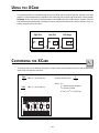
USING
THE
XC ARD
The crossover functions are controlled through the use of an XCard and can be set for high-pass, low-pass or full range
operation. The XCard shipped with your amplifier is set for Full Range. Each crossover card has two faces: one face operates
Full Range, the other has arrows to indicate the edge for selecting HP (high-pass) or LP (low-pass) operation. Orient the
card with the desired operating edge, indicated by the arrow, toward the socket terminals inside the amplifier. Firmly, but
carefully, plug the card into the socket.
High-Pass
➝
HP
➝
LP
THE
HP
➝
➝
C USTOMIZING
Low-Pass
LP
Full Range
FULL ↕
XC ARD
a
d
v
a
n
c
e
d
O
p
e
r
a
t
i
o
n
The crossover point can be altered by changing the 4 resistor values. Use the following formula to select the appropriate
resistor value to be placed on the XCard.
3386
= R (in kΩ) for .047mf cap
fo
FULL
R2
R1
R2
Crossover Card
High Pass
Low Pass
Full Range
1
2πfoc
Where: R = Ω
fo = desired crossover frequency
c = capacitor in farads
ex: .047 x 10-6 for .047mf cap
= R (in kΩ) for .022mf cap
R1
7234
fo
The actual formula is: R =
– 14 –
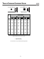
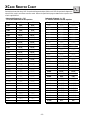
XC ARD R ESISTOR C HART
a
d
v
a
n
c
e
d
Our tests have shown that using 0.047µf capacitors for frequencies below 100Hz, and 0.022mf capacitors for frequencies
above 100Hz, result in more linear crossover control. Refer to the Specifications page to determine the capacitor value
of each supplied XCard.
Butterworth Alignment Q = .707
1% resistors used with 0.047mF capacitors
Butterworth Alignment Q = .707
1% resistors used with 0.022mF capacitors
R1
R2
20Hz
357kΩ
357kΩ
133kΩ
25Hz
287kΩ
287kΩ
110kΩ
110kΩ
30Hz
237kΩ
237kΩ
35Hz
95.3kΩ
95.3kΩ
35Hz
205kΩ
205kΩ
40Hz
84.5kΩ
84.5kΩ
40Hz
178kΩ
178kΩ
45Hz
75kΩ
75kΩ
45Hz
162kΩ
162kΩ
50Hz
68.1kΩ
68.1kΩ
50Hz
143kΩ
143kΩ
55Hz
61.9kΩ
61.9kΩ
55Hz
130kΩ
130kΩ
60Hz
56.2kΩ
56.2kΩ
60Hz
121kΩ
121kΩ
65Hz
52.3kΩ
52.3kΩ
65Hz
110kΩ
110kΩ
70Hz
48.7kΩ
48.7kΩ
70Hz
102kΩ
102kΩ
75Hz
45.3kΩ
45.3kΩ
75Hz
95.3kΩ
95.3kΩ
80Hz
42.2kΩ
42.2kΩ
80Hz
90.9kΩ
90.9kΩ
85Hz
40.2kΩ
40.2kΩ
85Hz
84.5kΩ
84.5kΩ
90Hz
37.4kΩ
37.4kΩ
90Hz
80.6kΩ
80.6kΩ
200Hz
16.9kΩ
16.9kΩ
200Hz
35.7kΩ
35.7kΩ
300Hz
11.3kΩ
11.3kΩ
300Hz
23.7kΩ
23.7kΩ
400Hz
8.45kΩ
8.45kΩ
400Hz
17.8kΩ
17.8kΩ
500Hz
6.65kΩ
6.65kΩ
500Hz
14.3kΩ
14.3kΩ
600Hz
5.62kΩ
5.62kΩ
600Hz
12.1kΩ
12.1kΩ
700Hz
4.75kΩ
4.75kΩ
700Hz
10.2kΩ
10.2kΩ
800Hz
4.22kΩ
4.22kΩ
800Hz
9.9kΩ
9.9kΩ
900Hz
3.74kΩ
3.74kΩ
900Hz
86kΩ
86kΩ
1.0kHz
3.40kΩ
3.40kΩ
1.0kHz
7.15kΩ
7.15kΩ
1.2kHz
2.80kΩ
2.80kΩ
1.2kHz
6.04kΩ
6.04kΩ
2kHz
1.69kΩ
1.69kΩ
2.0kHz
3.57kΩ
3.57kΩ
3kHz
1.10kΩ
1.10kΩ
3.0kHz
2.37kΩ
2.37kΩ
4kHz
845Ω
845Ω
4.0kHz
1.76kΩ
1.76kΩ
5kHz
665Ω
665Ω
5.0kHz
1.43kΩ
1.43kΩ
6kHz
562Ω
562Ω
6.0kHz
1.21kΩ
1.21kΩ
7kHz
487Ω
487Ω
7.0kHz
10.2kΩ
10.2kΩ
8kHz
422Ω
422Ω
8.0kHz
909Ω
909Ω
Frequency
R1
R2
20Hz
169kΩ
169kΩ
25Hz
133kΩ
30Hz
Frequency
– 15 –
O
p
e
r
a
t
i
o
n
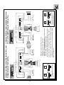
250.2 INSTALLATION
®
250.2 Power Connections (Option #1)
Power
REM
Dual B+
Dual GND
Connect to remote
turn-on lead of
source unit.
Connect to chassis
ground of vehicle*
Less than 18"
+
–
Connect to B+ of battery
with a 60 amp fuse.
*Keep wire as short as possible.
250.2 Power Connections (Option #2)
Power
Dual B+
Dual GND
Connect to remote
turn-on lead of
source unit.
Less than 18"
+
–
Connect to B+ of battery
with a 60 amp fuse.
*Keep wire as short as possible.
– 16 –
1 farad • 20 VDC • 95°C
cap
1.0punch
®
the connecting
®
Connect to chassis
ground of vehicle*
®
REM
Optional energy
storage capacitor
®
I
N
S
T
A
L
L
A
T
I
O
N
®
Stereo Operation
RCA
Input
Unbal.
Speaker
+ L –
0°-180°
L (Mono)
R
Bal.
Pass
Thru
Gain
Bal.
Input
L
EZ-180°-0°
Bridged
R
Gain
–
–
2Ω Min.
2Ω Min.
+
+
•
•
•
•
•
•
•
Speaker
– R +
RCA inputs are connected to both left and right channels
Signal Input Switch selected to Unbalanced for RCA input
Left Phase Switch set to 0°
Right Phase Switch set to 0°
Gain for left and right channels operate independently
Impedance for each channel should be 2Ω minimum
XCard can be High-Pass, Low-Pass or Full Range position
Stereo/Mono Operation
RCA
Input
Unbal.
Speaker
+ L –
0°-180°
Gain
L (Mono)
R
Bal.
Pass
Thru
Bal.
Input
L
EZ-180°-0°
Bridged
R
Gain
–
+
2Ω min.
2Ω min.
+
+
Speaker
Terminal
Speaker
– R +
–
+
–
4Ω min.
•
•
•
•
•
•
•
•
•
•
RCA inputs are connected to both left and right channels
Signal Input Switch selected to Unbalanced for RCA input
Left Phase Switch set to 0°
Right Phase Switch set to 180° for stereo/mono operation
All speaker polarity on right channel is inverted to correct for signal phase
Gain for left and right channels set equally to balance the subwoofer
Impedance for each channel should be 2Ω minimum
Impedance for bridged channel should be 4Ω minimum
XCard is in Full Range position
Passive crossovers are needed for proper stereo/mono operation
– 17 –
–
Speaker
Terminal
®
I
N
S
T
A
L
L
A
T
I
O
N
®
Bridged Operation
RCA Input
Unbal.
Speaker
+ L –
0°-180°
L (Mono)
R
Bal.
Gain
+
Speaker
Terminal
EZ-180°-0°
Bridged
Bal.
Input
Pass
Thru
L
R
Speaker
– R +
Gain
+
–
Speaker
Terminal
–
4Ω min.
•
•
•
•
•
•
•
•
RCA inputs are connected to both left and right channels
Signal Input Switch selected to Unbalanced for RCA input
Left Phase Switch set to 0°
Right Phase Switch set to 180°
Inverting the right signal will allow the bridged woofer to operate correctly
Gain for left and right channels set equally to balance the subwoofer
Impedance for bridged channel should be 4Ω minimum
XCard is in High-Pass, Low-Pass or Full Range position
EZ-Bridged Operation
Mono
Input
Unbal.
Speaker
+ L –
0°-180°
Gain
+
Speaker
Terminal
L (Mono)
R
Bal.
Bal.
Input
Pass
Thru
L
EZ-180°-0°
Bridged
R
+
Speaker
– R +
Gain
–
Speaker
Terminal
–
4Ω min.
•
•
•
•
•
•
RCA input is connected to L (Mono) input
Signal Input Switch to Unbalanced for RCA input
Left Phase Switch at 0°
Right Phase Switch set to E-Z Bridge for the following to occur:
L (Mono) RCA input to drive both the left and right channels
Left Gain will control both the left and right channels
Right Phase will be inverted 180° which will allow the bridged woofer to operate
correctly
Impedance for bridged channel should be 4Ω minimum
XCard is in the High-Pass, Low-Pass or Full Range position
– 18 –
®
I
N
S
T
A
L
L
A
T
I
O
N
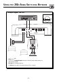
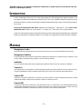
U S I N G T H E 250.2 SIGNAL S W I T C H I N G N E T W O R K
®
®
I
N
S
T
A
L
L
A
T
I
O
N
The Punch 250.2 Power amplifier has a crossover switching network which enables you to:
•
•
•
•
•
“Audiophile Bypass” the 250.2 and Pass-Thru
Configure a 12dB per octave filter for both 250.2 and Pass-Thru
“Audiophile Bypass” the 250.2 and configure a 12dB per octave filter for the Pass-Thru
Configure a 24dB per octave filter for the 250.2 and “Audiophile Bypass” the Pass-Thru
Configure a 12dB per octave bandpass filter for the 250.2 and “Audiophile Bypass” the Pass-Thru
The crossover switching network allows the crossover to be distributed to the amplifier and Pass Thru in many different
configurations. The orientation of both switches configure the distribution pattern to where the crossover signal will
be routed.
®
P
XCard Options
Amplifier
Pass Thru
250.2 AMPLIFIER
W
E
R
125 Watts X 2 into 4 Ohms
with less than 0.05% THD + N from 20-20kHz
225 Watts X 2 into 2 Ohms
with less than 0.10% THD + N from 20-20kHz
High-Pass
XCard 2
HP
XCard 1
O
LP
Amplifier
Amplifier
XCard 1
XCard 2
XCard 2
®
ROCKFORD CORPORATION
MADE IN THE USA
Low-Pass
LP
*Bridging Note: The Punch 250.2 can be
bridged in many configurations. Refer to your
owner's manual to determine which mode will
work best in your system.
XCard 1
XCard 2
XCard 1
Not Used
HP
Audiophile Bypass
Not Used
XCard 1
Amp Only
FULL
Audiophile Bypass
Not Used
Full Range
Pass Thru
XCard 2
– 19 –
®
“Audiophile Bypass” as it affects the output of the 250.2 and Pass-Thru.
XCard not required.
R
AUD
VOL
PWR
CLOCK
DISC
AMFM
®
ST
Ch
LD RDM RPT
AUTO
DSPL
SEL
ILLUM
P.SCN
LOUD
D.SCN
SCAN
RPT
RDM
DIM
PAUSE
1
2
3
4
5
6
TUNE
XCard 1
XCard 2
®
Unbal.
Speaker
+ L –
0°-180°
Gain
L (Mono) R
Bal.
Pass
Thru
Bal.
Input
L
R
EZ-180°-0 °
Bridged
Speaker
– R +
Gain
+
+
–
Full Range
20Hz
–
Full Range
20kHz
+
–
20Hz
20kHz
12dB/Octave Low-Pass
20Hz
80Hz
20kHz
• 250.2 bypasses the circuitry of XCard 1 and XCard 2
• Pass-Thru bypasses the circuitry of XCard 1 and XCard 2
• The 250.2 and Pass-Thru are in Audiophile Bypass mode which maintains signal integrity
resulting in a better sounding amplifier
• The XCards do not need to be inserted to allow the 250.2 or Pass-Thru to operate
– 20–
®
I
N
S
T
A
L
L
A
T
I
O
N
®
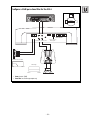
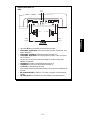
Configure a 12dB per octave filter for both the 250.2 and Pass-Thru.
250x22
XCard*
Pass Thru
XCard*
HP
XCard 1
R
AUD
VOL
PWR
DISC
AMFM
®
ST
Ch
LD RDM RPT
LP
XCard 2
SEL
CLOCK
AUTO
ILLUM
DSPL
P.SCN
LOUD
D.SCN
SCAN
RPT
RDM
DIM
PAUSE
1
2
3
4
5
6
TUNE
®
Unbal.
Speaker
+ L –
0°-180°
L (Mono) R
Bal.
Gain
Pass
Thru
Bal.
Input
L
R
EZ-180°-0 °
Bridged
Speaker
– R +
Gain
+
–
+
12dB/Octave High-Pass
20Hz 80Hz
12dB/Octave High-Pass
20kHz
+
–
12dB/Octave Low-Pass
20Hz
80Hz
20kHz
• 250.2 uses output from XCard 1
• Pass-Thru uses output from XCard 2
– 21 –
20Hz 80Hz
20kHz
–
®
I
N
S
T
A
L
L
A
T
I
O
N
®
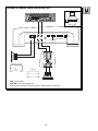
“Audiophile Bypass” the 250.2 and configure a 12dB per octave filter
for the Pass-Thru.
Pass Thru XCard
XCard not required.
LP
R
AUD
VOL
PWR
DISC
AMFM
®
ST
Ch
LD RDM RPT
CLOCK
AUTO
DSPL
P.SCN
SEL
ILLUM
LOUD
D.SCN
SCAN
RPT
RDM
DIM
PAUSE
1
2
3
4
5
6
TUNE
XCard 1
XCard 2
®
Unbal.
Speaker
+ L –
0°-180°
Gain
L (Mono) R
Bal.
Pass
Thru
Bal.
Input
L
R
EZ-180°-0 °
Bridged
Speaker
– R +
Gain
+
+
–
Full Range
20Hz
–
Full Range
20kHz
+
–
20Hz
20kHz
12dB/Octave Low-Pass
20Hz
80Hz
20kHz
• 250.2 bypasses the circuitry of XCard 1
• Pass-Thru uses output from XCard 2
• The 250.2 is in Audiophile Bypass mode which maintains signal integrity resulting in a better
sounding amplifier
• XCard 1 does not need to be inserted to allow the 250.2 to operate
– 22 –
®
I
N
S
T
A
L
L
A
T
I
O
N
– 23 –
–
+
ST
®
Ch
LD RDM RPT
2
1
AUTO
3
RPT
P.SCN
Speaker
+ L –
SCAN
DSPL
CLOCK
D.SCN
ILLUM
LOUD
5
DIM
SEL
XCard 1
XCard 2
HP
HP
20Hz
250x 2 2
XCard*
Gain
R
+
R
Full Range
L
L (Mono) R
Pass
Thru
TUNE
Bal.
Unbal.
6
PAUSE
0°-180°
4
RDM
250x 2 2
XCard*
20kHz
24dB/Octave High-Pass
®
DISC
AMFM
20Hz
PWR
AUD
*Note: Both XCard inserted as
HP or LP.
VOL
20kHz
–
Bal.
Input
–
+
VOL
–
+
PWR
AUD
ST
®
Ch
LD RDM RPT
2
SCAN
DSPL
CLOCK
AUTO
3
RPT
P.SCN
Speaker
+ L –
1
D.SCN
20Hz
ILLUM
LOUD
5
DIM
6
PAUSE
SEL
Gain
R
R
Full Range
+
L
L (Mono) R
Pass
Thru
TUNE
20Hz
Bal.
Unbal.
0°-180°
4
RDM
20kHz
12dB/Octave 100-275Hz
®
DISC
AMFM
must be customized to enable proper bandpass operation. Refer to
“Using the XCard” on page 14 for more information. Additional crossover
card frequencies are available from your Authorized Rockford Fosgate
Dealer. (See page 40)
20kHz
–
Bal.
Input
XCard 2
LP
250x 2 2
XCard*
–
+
*Note: One XCard inserted HP,
other XCard inserted LP.
XCard 1
HP
250x 2 2
XCard*
20kHz
12dB/Octave 100-275Hz
Speaker
– R +
20Hz
Gain
EZ-180°-0 °
Bridged
Configure a 12dB per octave bandpass filter for the
250.2 and “Audiophile Bypass” the Pass-Thru.
• 250.2 uses output from XCard 1 and XCard 2
• Pass-Thru bypasses XCard 1 and XCard 2
• Pass-Thru is in Audiophile Bypass mode which maintains signal
integrity resulting in a better sounding amplifier
*The 250.2 is shipped with 80Hz XCards. At least one of the XCards
20kHz
24dB/Octave High-Pass
Speaker
– R +
20Hz
Gain
EZ-180°-0 °
Bridged
Configure a 24dB per octave filter for the 250.2 and
“Audiophile Bypass” the Pass-Thru.
®
®
I
N
S
T
A
L
L
A
T
I
O
N
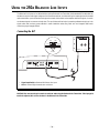
U SING
THE
250.2 B ALANCED L INE I NPUTS
The Balanced Line Inputs can be utilized with the optional Balanced Line Transmitter. Unlike standard RCA cables that use
two wires to carry the audio signal and ground, balanced lines use three. In a balanced line, the output signal and its inverted
replica travel down a pair of wires where the ground connects via the shield. As the amplifier receives the signals, it cancels
out whatever signals are common to both wires. The use of balanced lines helps in preventing radiated noise pickup in the
signal cables and has been proven effective in studio installation where long cable runs and magnetic fields make
maintaining signal integrity difficult.
Connecting the BLT
®
®
BALANCED LINE TRANSMITTER
+18V
–18V
– R. SIG
+ R. SIG
– L. SIG
+ L. SIG
BALANCED LINE
LED
OUTPUT
L
INPUT
R
SHIELD
L
(Mono)
L
Speaker
+ L –
Gain
Phase
0 – 180°
Bass
EQ
Balanced
Unbalanced
L
R
R
Pass Thru Pass Thru
R
Balanced
Input
Gain
EZ Bridged
Speaker
– R +
180°- 0°
• Signal Input Switch to Balanced for Balance Line Input
• Gain for Left and Right channels set to minimum
CAUTION!! You must turn the gain controls to minimum when using the Balanced Line Transmitter. If the input gains
need to be adjusted, this can now be done in the Balanced Line Transmitter.
– 24 –
Level Setting the BLT
a
d
v
a
n
c
e
d
R
AUD
VOL
PWR
DISC
AMFM
ST
®
Ch
LD RDM RPT
CLOCK
AUTO
ILLUM
DSPL
P.SCN
LOUD
SEL
D.SCN
SCAN
RPT
RDM
DIM
PAUSE
1
2
3
4
5
6
TUNE
®
1kHz Test Tone @ “0dB”
8.0 VAC
®
®
BALANCED LINE TRANSMITTER
L
+
•
•
•
•
•
•
•
•
–
R
L
R
Disconnect Speaker(s) from the 250.2
CD Software used to set levels is a test tone of 1kHz at “0dB” or “All Bits High”
Source Unit set to 3/4 volume (or maximum unclipped output)
Remove BLT Cover to access test pads and gain pots
AC Voltmeter set to AC Volts
AC Voltmeter “–” connected to RCA shield of BLT
AC Voltmeter “+” connected to test pad inside the BLT
Adjust BLT Gain from 2.5 VRMS min. to 8.0 VRMS max per test pad (see chart below)
Be sure the time index reads greater than 30 seconds on source unit.
Gain Overlap
BLT Output (AC Volts)
Performance Characteristics
+0dB*
2.5 VRMS
Best S/N Ratio, Reduced SPL
(Used for Optimum Sound Quality)
+5dB
4.5 VRMS
Good S/N Ratio & SPL
(Use for Audiophile Listener)
+10dB
8.0 VRMS
Best Compromise between S/N Ratio & SPL
(Used for Average Listener)
*Absence of gain overlap will reduce SPL and may not permit amplifier to reach full output power due to various CD
software.
– 25 –
O
p
e
r
a
t
i
o
n
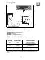
250.1 INSTALLATION
®
250.1 Power Connections (Option #1)
REM
Dual B+
Dual GND
Connect to remote
turn-on lead of
source unit.
Connect to chassis
ground of vehicle*
Less than 18"
+
–
Connect to B+ of battery
with a 60 amp fuse.
*Keep ground connections as close to each other as possible.
250.1 Power Connections (Option #2)
Dual B+
Dual GND
Connect to remote
turn-on lead of
source unit.
Less than 18"
+
1 farad • 20 VDC • 95°C
cap
1.0punch
®
the connecting
®
Connect to chassis
ground of vehicle*
®
REM
Optional energy
storage capacitor
–
Connect to B+ of battery
with a 60 amp fuse.
*Keep ground connections as close to each other as possible.
– 26 –
®
I
N
S
T
A
L
L
A
T
I
O
N
Mono Operation
®
RCA Input
L (Mono) R
Power
Speaker
–
+
Gain
L Pass Thru R Pass Thru
–
L + R / L (Mono)
RCA Inputs
+
2Ω minimum
•
Signal Input Switch set to L+R for RCA input
•
Phase Switch set to 0°
•
Impedance should be 2Ω minimum
•
XCard can be set for High-Pass, Low-Pass or Full Range
X-Over
0°-180°
24dB/12dB/0dB
– 27 –
®
I
N
S
T
A
L
L
A
T
I
O
N
•
•
•
•
+
–
Gain
L Pass Thru R Pass Thru
L (Mono) R
X-Over
0°-180°
24dB/12dB/0dB
L + R / L (Mono)
RCA Inputs
Power
Signal Input Switch (250.1 #1 / #2) set to L(Mono) for single RCA input)
Phase Switch (250.1 #1/2) set to 0°
Impedance for each amplifier should be 2Ω minimum
XCard for each amplifier can be set for High-Pass, Low-Pass or Full Range
2Ω
minimum
Speaker
–
+
250.1 #1
L
RCA Input
R
Stereo Operation using two Punch 250.1 Power Amplifiers
2Ω
minimum
+
–
250.1 #2
Speaker
–
+
Gain
L Pass Thru R Pass Thru
L (Mono) R
X-Over
0°-180°
24dB/12dB/0dB
L + R / L (Mono)
RCA Inputs
Power
®
– 28 –
®
I
N
S
T
A
L
L
A
T
I
O
N
– 29 –
Passive Crossovers are needed for proper stereo/mono operation
•
Impedance for each stereo channel should be 2Ω minimum
•
Impedance for bridged channel should be 4Ω minimum
Gain (250.1 #1/#2) set equally to balance the subwoofer
•
XCard (250.1 #1/#2) set to Full Range
All speaker polarity on right amplifier is inverted to correct for signal phase
•
Phase Switch (250.1 #2) set to 180°
•
•
•
Phase Switch (250.1 #1) set to 0°
4Ω minimum
low frequency
–
•
+ Speaker
Terminal
+
X-Over
0°-180°
24dB/12dB/0dB
L + R / L (Mono)
RCA Inputs
Power
Signal Input Switch (250.1 #1/#2) set to L(Mono) for single RCA input
+
–
Gain
L Pass Thru R Pass Thru
L (Mono) R
•
2Ω minimum
high frequency
Speaker
–
+
250.1 #1
Stereo/Mono Operation
L
RCA Input
R
2Ω minimum
high frequency
–
+
– Speaker
Terminal
Speaker
–
+
250.1 #2
Gain
L Pass Thru R Pass Thru
L (Mono) R
X-Over
0°-180°
24dB/12dB/0dB
L + R / L (Mono)
RCA Inputs
Power
®
®
I
N
S
T
A
L
L
A
T
I
O
N
Gain
Phase Switch (250.1 #1) set to 0°
Phase Switch (250.1 #2) set to 180°
Gain (250.1#1/#2) set equally to balance the subwoofer
Impedance for bridged channel should be 4Ω minimum
XCard (250.1 #1/#2) set identically as High-Pass, Low-Pass or Full Range
•
•
•
•
–
•
4Ω minimum
+
X-Over
0°-180°
24dB/12dB/0dB
L + R / L (Mono)
RCA Inputs
Power
Signal Input Switch (250.1 #2) set to L+R for RCA input
L Pass Thru R Pass Thru
L (Mono) R
•
+ Speaker
Terminal
Speaker
–
+
250.1 #1
RCA Input
Bridged Mono Operation
Speaker
–
+
250.1 #2
Gain
– Speaker
Terminal
L Pass Thru R Pass Thru
L (Mono) R
X-Over
0°-180°
24dB/12dB/0dB
L + R / L (Mono)
RCA Inputs
Power
®
– 30 –
®
I
N
S
T
A
L
L
A
T
I
O
N
USING
THE
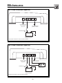
250.1 SIGNAL S W I T C H I N G N E T W O R K
“Audiophile Bypass” the 250.1
XCard not required.
R
AUD
VOL
PWR
DISC
AMFM
ST
®
Ch
LD RDM RPT
CLOCK
AUTO
ILLUM
DSPL
P.SCN
LOUD
SEL
D.SCN
SCAN
RPT
RDM
DIM
PAUSE
1
2
3
4
5
6
TUNE
XCard
®
L (Mono) R
Power
Speaker
–
+
X-Over
0°-180°
24dB/12dB/0dB
Gain
L Pass Thru R Pass Thru
L + R / L (Mono)
RCA Inputs
–
+
Full Range
Full Range
20Hz
20kHz
+
20Hz
–
20kHz
• Xover is set to 0dB
• The 250.1 is in Audiophile Bypass mode which maintains signal integrity resulting in a
better sounding amplifier
• Pass-Thru has Full Range output only
• The XCard does not need to be inserted to allow the 250.1 to operate
– 31 –
®
®
I
N
S
T
A
L
L
A
T
I
O
N
®
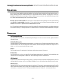
Configure a 12dB per octave filter for the 250.1
LP
R
AUD
VOL
PWR
DISC
AMFM
ST
®
Ch
LD RDM RPT
CLOCK
AUTO
DSPL
P.SCN
SEL
ILLUM
LOUD
D.SCN
SCAN
RPT
RDM
DIM
PAUSE
1
2
3
4
5
6
TUNE
®
XCard
L (Mono) R
Power
Speaker
–
+
X-Over
0°-180°
24dB/12dB/0dB
Gain
L Pass Thru R Pass Thru
L + R / L (Mono)
RCA Inputs
–
+
12dB/Octave Low-Pass
Full Range
20Hz
20kHz
+
20Hz
–
20kHz
• Xover is set to 12dB
• Pass-Thru has Full Range output only
– 32 –
®
I
N
S
T
A
L
L
A
T
I
O
N
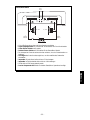
Configure a 24dB per octave filter for the 250.1
®
LP
R
AUD
VOL
PWR
DISC
AMFM
®
ST
Ch
LD RDM RPT
SEL
CLOCK
AUTO
ILLUM
DSPL
P.SCN
LOUD
D.SCN
SCAN
RPT
RDM
DIM
PAUSE
1
2
3
4
5
6
TUNE
®
XCard
L (Mono) R
Power
Speaker
–
+
X-Over
0°-180°
24dB/12dB/0dB
Gain
L Pass Thru R Pass Thru
L + R / L (Mono)
RCA Inputs
–
+
24dB/Octave Low-Pass
Full Range
20Hz
20kHz
+
20Hz
–
20kHz
• Xover is set to 24dB
• Pass-Thru has Full Range output only
• By switching the crossover to 24dB, the signal is routed through the XCard twice
– 33 –
®
I
N
S
T
A
L
L
A
T
I
O
N
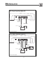
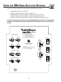
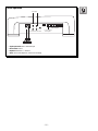
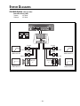
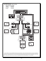
S YSTEM D IAGRAMS
250 Watt System (rated @ 4 ohms)
Total Power Delivery (RMS)
Tweeters
450 Watts
Midrange
450 Watts
R
AUD
VOL
PWR
DISC
AMFM
®
80Hz HP
ST
Ch
LD RDM RPT
CLOCK
AUTO
DSPL
P.SCN
SEL
ILLUM
LOUD
D.SCN
SCAN
RPT
RDM
DIM
PAUSE
1
2
3
4
5
6
TUNE
®
80Hz HP
250.2
TX-4183
TX-4183
TX-4183
TX-4183
PWR-14X
3kHz-20kHz
PWR-14X
3kHz-20kHz
18dB/octave HP
18dB/octave HP
PWR-14X
PWR-14X
PWR-54
4Ω
PWR-54
4Ω
80Hz-20kHz
80Hz-20kHz
24dB/octave HP
24dB/octave HP
– 34 –
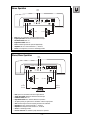
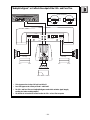
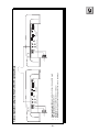
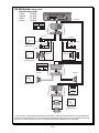
500 Watt System (rated @ 4 ohms)
Total Power Delivery (RMS)
Tweeters
450 Watts
Midrange
450 Watts
Woofers
500 Watts
R
AUD
VOL
PWR
DISC
AMFM
®
ST
Ch
LD RDM RPT
SEL
CLOCK
AUTO
ILLUM
DSPL
P.SCN
LOUD
D.SCN
SCAN
RPT
RDM
DIM
PAUSE
1
2
3
4
5
6
TUNE
®
Pass-Thru
Pass-Thru
80Hz HP
80Hz LP
250.2
TX-4183
TX-4183
TX-4183
TX-4183
PWR-14X
3kHz-20kHz
PWR-14X
3kHz-20kHz
18dB/octave HP
18dB/octave HP
PWR-14X
PWR-14X
PWR-54
4Ω
PWR-54
4Ω
80Hz-20kHz
80Hz-20kHz
12dB/octave HP
24dB/octave HP
30Hz HP*
XCard
250.1
30Hz High-Pass used
as a sub-sonic filter.
4Ω
30Hz-80Hz
12dB/octave BP
RFR-1415
• A sub-sonic filter is a high-pass filter that limits the input signal below a certain motion below that frequency. At very low frequencies
a woofer has no output, just motion. If you try to drive this woofer at these lower frequencies, the woofer could self-destruct. Please refer
to the crossover section of the manual or see your local Authorized Rockford Fosgate Dealer for more information.
– 35 –
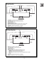
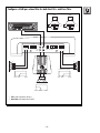
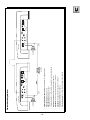
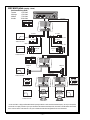
750 Watt System (rated @ 4 ohms)
Total Power Delivery (RMS)
Tweeters
450 Watts
Midrange
450 Watts
Midbass
250 Watts
Woofers
500 Watts
R
AUD
VOL
PWR
DISC
AMFM
®
ST
Ch
LD RDM RPT
CLOCK
AUTO
DSPL
P.SCN
SEL
ILLUM
LOUD
D.SCN
SCAN
RPT
RDM
DIM
PAUSE
1
2
3
4
5
6
TUNE
®
Pass-Thru
Pass-Thru
400Hz HP
400Hz LP
250.2
TX-4183
TX-4183
TX-4183
TX-4183
PWR-14X
3kHz-20kHz
PWR-14X
18dB/octave HP
PWR-14X
PWR-14X
PWR-54
4Ω
PWR-54
4Ω
400Hz-20kHz
12dB/octave HP
Pass-Thru
80Hz HP
80Hz LP
250.2
PWR-64
4Ω
PWR-64
4Ω
80Hz-400Hz
12dB/octave BP
30Hz HP*
XCard
250.1
30Hz High-Pass used
as a sub-sonic filter.
4Ω
30Hz-80Hz
12dB/octave BP
RFR-1415
• A sub-sonic filter is a high-pass filter that limits the input signal below a certain motion below that frequency. At very low frequencies
a woofer has no output, just motion. If you try to drive this woofer at these lower frequencies, the woofer could self-destruct. Please refer
to the crossover section of the manual or see your local Authorized Rockford Fosgate Dealer for more information.
– 36 –
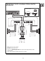
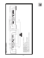
1000 Watt System (rated @ 4 ohms)
Total Power Delivery (RMS)
Tweeters
450 Watts
Midrange
450 Watts
Midbass
250 Watts
Woofers
1000 Watts
R
AUD
VOL
PWR
DISC
AMFM
®
ST
Ch
LD RDM RPT
SEL
CLOCK
AUTO
ILLUM
DSPL
P.SCN
LOUD
D.SCN
SCAN
RPT
RDM
DIM
PAUSE
1
2
3
4
5
6
TUNE
®
Pass-Thru
Pass-Thru
400Hz HP
400Hz LP
250.2
TX-4183
TX-4183
TX-4183
TX-4183
PWR-14X
3kHz-20kHz
PWR-14X
18dB/octave HP
PWR-14X
PWR-14X
PWR-54
4Ω
PWR-54
4Ω
400Hz-20kHz
12dB/octave HP
Pass-Thru
80Hz HP
80Hz LP
250.2
PWR-64
4Ω
PWR-64
4Ω
Pass-Thru
8 0Hz-400Hz
12dB/octave BP
30Hz HP*
30Hz HP*
XCard
XCard
250.1
250.1
30Hz High-Pass used
as a sub-sonic filter.
30Hz High-Pass used
as a sub-sonic filter.
4Ω
4Ω
30Hz-80Hz
30Hz-80Hz
12dB/octave BP
12dB/octave BP
RFR-1415
RFR-1415
• A sub-sonic filter is a high-pass filter that limits the input signal below a certain motion below that frequency. At very low frequencies
a woofer has no output, just motion. If you try to drive this woofer at these lower frequencies, the woofer could self-destruct. Please refer
to the crossover section of the manual or see your local Authorized Rockford Fosgate Dealer for more information.
– 37 –
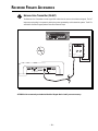
ROCKFORD FOSGATE ACCESSORIES
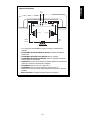
Balanced Line Transmitter (FG-BLT)
®
The Balanced Line Transmitter converts signal RCA cables from the source unit to balanced signals. The BLT
improves sound quality in the system by eliminating noises generated by vehicle electrical systems. The BLT is
available for Rockford Fosgate products that offer a balanced input.
R
AUD
VOL
DISC
AMFM
PWR
ST
Ch
LD RDM RPT
®
CLOCK
AUTO
ILLUM
DSPL
P.SCN
LOUD
SEL
D.SCN
SCAN
RPT
RDM
DIM
PAUSE
1
2
3
4
5
6
TUNE
®
®
®
BALANCED LINE TRANSMITTER
NOISE
BALANCED LINE
LED
OUTPUT
L
(Mono)
L
Speaker
+ L –
Gain
Phase
0 – 180°
Bass
EQ
Balanced
Unbalanced
L
R
INPUT
R
R
R
Pass Thru Pass Thru
L
Balanced
Input
Gain
EZ Bridged
Speaker
– R +
180°- 0°
ATTENTION: We recommend your Authorized Rockford Fosgate Dealer install your new accessory.
– 38 –
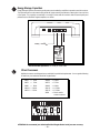
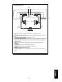
Energy Storage Capacitors
®
Energy Storage Capacitors are used to provide extra current needed by amplifiers to reproduce musical transients.
The capacitors also have the natural ability to filter AC ripple caused by the alternator, reducing the chance of noise
in the system. The capacitors are available in a variety of values and will maximize both the sound quality and
performance that Rockford Fosgate amplifiers can deliver.
Power
REM
Dual B+
Dual GND
Battery +
®
®
the connecting
®
1.0punch
cap
1 farad • 20 VDC • 95°C
• Recommended capacitance is 1 farad per 1000 watts
XCard Crossovers
Additional crossover card frequencies are available for specialized requirements. You can get the following
XCards from your Authorized Rockford Fosgate Dealer.
XM50
XM70
XM80
XM100
XM150
= 50Hz
= 70Hz
= 80Hz
= 100Hz
= 150Hz
XM200
XM275
XM400
XM4.5k
XM6.5k
XM00
=
=
=
=
=
=
200Hz
275Hz
400Hz
4,500Hz
6,500Hz
Blank card for
custom crossover
FULL
R2
High Pass
Low Pass
Full Range
R1
R2
Crossover Card
R1
®
ATTENTION: We recommend your Authorized Rockford Fosgate Dealer install your new accessory.
– 39 –
TROUBLESHOOTING
Symptom
Amplifier does not turn on.
(Power LED is off)
Amplifier has no sound.
(Power LED is on)
TROUBLE-S
H
O
O
T
I
N
G
Diagnosis
Remedy
Voltage applied to the REM terminal of the
amplifier is not between 10.5 and 15.5
volts or there is no voltage present.
Check the alternator, battery, fuse, and
wiring and repair as necessary. If the voltage is above 15.5 volts, have the electrical
system inspected by an authorized car
service center.
Voltage to the B+ terminal of the amplifier
is not between 10.5 and 15.5 volts or there
is no voltage present.
Check the alternator, battery, fuse, and
wiring and repair as necessary. If the voltage is above 15.5 volts, have the electrical
system inspected by an authorized car
service center.
Amplifier is not properly grounded.
Check wiring and repair as necessary.
RCA Input from source unit is not connected
or not functioning properly.
Check connections, substitute with known
working source and cables and repair or
replace as necessary.
When using the BLT, Balanced Line Input
from BLT is not connected or not functioning properly.
Check connections, substitute with known
working BLT and cables and repair or
replace as necessary.
Unbalanced/Balanced Line switch is not
selected for corresponding input.
Check switch position and correct as necessary.
Amplifier is in E-Z Bridge operation but
incorrect signal input, speaker wiring, and/
or left channel 180° phase selection is
chosen.
Check signal, speaker wiring, and left channel phase selection installation and correct
as needed.
XCards are missing or not placed properly
in crossover slots and/or switches are not
properly selected.
Check crossover switches and XCard positions and repair or replace as necessary.
Speaker leads are shorted to each other or
to the chassis of the vehicle.
Disconnect existing speakers and test with
known working speakers and wires. If amplifier plays, check and repair wiring and
installation of speakers as necessary.
Speakers are defective.
Disconnect existing speakers and test with
known working speakers. If amplifier plays,
check and repair speakers as necessary.
– 40 –
Symptom
Speaker Output Low
or Distorted
Amplifier Noise
(Turn-on Pop)
No output from Pass-Thru
output of amplifier.
Diagnosis
Remedy
TROUBLE-S
H
O
O
T
I
N
G
Input gain(s) for amplifier incorrectly set.
Readjust input gains of amplifier.
Source unit output too low or source unit
has no output.
Check system with known working source
and repair or replace original source as
needed.
Phase selection of amplifier incorrectly selected or speakers wired out of polarity from
the left to right channel.
Check speaker polarity and phase switch
position and correct as needed.
XCards are missing or not placed properly
in crossover slots and/or switches are not
properly selected.
Check crossover switches and XCard positions and repair or replace as necessary.
Low battery voltage or large voltage drops
to the amplifier under load.
Check the alternator, battery, fuse or circuit
breaker and power and ground wiring and
repair as necessary.
Voltage spike from output of preceding
component is entering amplifier through
input signal.
Disconnect input signal to amplifier and
turn amplifier on and off. If noise is eliminated, connect REM lead of amplifier to
source unit with a delay turn-on module.
Voltage spike from remote turn-on lead is
entering through REM input terminal.
Use different 12 volt source for REM lead of
amplifier (i.e., battery direct). If noise is
eliminated, use relay to isolate amplifier
from noise turn-on output.
RCA Input from source unit is not connected
or not functioning properly.
Check connections, substitute with known
working source and cables and repair or
replace as necessary.
When using the BLT, Balanced Line Input
from BLT is not connected or not functioning properly.
Check connections, substitute with known
working BLT and cables and repair or
replace as necessary.
Unbalanced/Balanced Line switch is not
selected for corresponding input.
Check switch position and correct as necessary.
XCards are missing or not placed properly
in crossover slots.
Check crossover switches and XCard positions and repair or replace as necessary.
– 41 –
Symptom
Low or distorted output from the
Pass-Thru output of the amplifier.
Diagnosis
Remedy
TROUBLE-S
H
O
O
T
I
N
G
Input gain(s) for amplifier incorrectly set.
Readjust input gains of amplifier.
Source unit output too low.
Check system with known working source
and repair or replace original source as
needed.
XCards are missing or not placed properly
in crossover slots and/or switches are not
properly selected.
Check crossover switches and XCard positions and repair or replace as necessary.
Low battery voltage or large voltage drops
to the amplifier under load.
Check the alternator, battery, fuse or circuit
breaker and power and ground wiring and
repair as necessary.
RCA cable or amplifier connected to PassThru output is defective.
Check connections, substitute with known
working amplifier or cables and repair or
replace as needed.
• If noise persists, see your local Authorized Rockford Fosgate Dealer.
– 42 –
AUTOSOUND 2000's
QUICK CHECK FOR TROUBLESHOOTING
CAR AUDIO SYSTEMS
Preface:
All audio systems exhibit noise; however, if the level of noise is low enough, and the signal level high enough, noise should not be
a problem. This means that it is very important that the signal level throughout the system be optimized BEFORE dealing with your
noise problem. Using a scope (or a small portable amplifier) and Track 99 (1kHz at all high bits) of Rockford Fosgate CD RFCD101 (Autosound 2000's CD #101) or Tracks 24 through 29 of Rockford Fosgate CD RF-CD102 (Autosound 2000's CD #102),
adjust the system so that when the maximum usable signal level of the deck is fed into the system, all the preamp level components
clip at the same time. However, we recommend up to as much as a 3:1 voltage overlap with the power amplifiers; i.e. an amplifier
with a 2 volt minimum sensitivity can be driven by up to 6 volts of signal.
Noise Overview:
Car audio electrical accessories are notorious for interfering with car audio systems. The interference commonly arises from three
areas:
1) Power line noise (5%), which can be attenuated with in-line noise filters,
2) Inadequate power supply isolation (45%), which can be cured with transformer signal coupling, additional isolated power
supplies, or changing out components, or
3) Inductive interference (45%) – including loop area inductive noise picked up by the signal cables – which can be remedied by
relocating or rewiring components, rerouting signal cables, or using twisted cable or balanced transmission systems.
Autosound 2000 1-2-3 Method of Logical Troubleshooting
I.
MUTE THE AMP(S). Insert a muting plug (shorted male RCA connector) into each amplifier channel. Turn up the amp
sensitivity. Start the car and turn on the headlights, air conditioning, brake lights, etc. Listen for noise in each speaker. Be very
picky here!
A.
If still noisy, substitute a small test speaker with short leads for the speakers, crossovers, and speaker leads in the car. If still
noisy, substitute an isolated power supply (120 VAC to 13.8 VDC bench supply or a small motorcycle battery) for the car's
alternator. If the amplifier is noisy with the test speaker, you have a BAD amp. Send it in. It really doesn't matter if it is quiet
or noisy while running on the isolated supply because you have a BAD amp. Send it in for repair and if it was quiet on the
isolated supply, indicate so on the repair tag.
B. If your muted amp is quiet, you've just joined 99.5% of car audio. Amps are usually very clean and do NOT pick up
unwanted noise! Continue on to Step II.
II. DECK TO AMP. Using a new set of signal cables, connect one channel from the output of the deck directly into one channel of
your clean amp. Run the cables outside the car and as far away as possible from the metal of the car. (For noise purposes,
consider a 2" thick cushion of electromagnetic energy emanating from every metal surface in the car.)
A.
If still noisy, congratulations, in all probability your equalizer, electronic crossover, DSP, whatchamacallit, are just fine. This
means that you can't get your deck playing quiet with your amp, right? Go to Step III.
B. If all is quiet, congratulations, in all probability your deck and amplifier(s) are fine – you obviously have a problem with
your equalizer, electronic crossover, DSP, etc. Skip on down to “Time for the Processors.”
– 43 –
III. MOVE THE DECK. If you're at this step, it's time to turn your system into an “amplified deck” by temporarily relocating the deck
right ON TOP of the clean amplifier. Then using very, very short signal cables, connect the output of the deck into the input of
the amp and test for noise. Play a zero bit track – silence – and make sure all is completely quiet.
A. If still noisy, you're in a heap of trouble. We suggest that you try another deck and give us a call so that we can put your
name into the record books. It's a bad car audio day for you.
B. If the deck is quiet, then congratulations, you're on your way to a successful installation. It is now time to slowly, methodically, reinstall the deck back into its final position. Test for noise each step of the way. If the noise returns, suspect the signal
cables. Forget shielding because it will have only a very, minimal effect within the audio band. We highly suggest using
twisted pair cables or a balanced transmission system for cable induced noise.
Time for Processors:
By the end of Step III, you should have the deck playing quietly with the amp, with the quiet cables quietly routed. So it's time to add
the signal processors – one at a time – back into the system. Simply repeat Steps II and III with the equalizer, then the electronic
crossover, etc. However, before MOVING THE SIGNAL PROCESSORS to the amplifier, we highly suggest that you power the noisy
process from an isolated power supply rather than the car's +12 volts DC and chassis ground. Make sure to also connect the turnon lead to the isolated power supply. If the processor is now quiet, then it is highly probable that the component has inadequate
isolation. Solutions include changing components or permanently adding an external isolated power supply (Call Autosound 2000
at 209-465-3450 for info on isolated power supplies).
Summation:
During the design stage of your vehicles, try to avoid using extra batteries and high output alternators. Extra batteries are nothing but
loads as soon as the engine is started and high output alternators usually make more noise than stock alternators. Also, extra
batteries installed in the trunk of a car will ALWAYS force extra ripple current to flow over the car.
Install Stiffening Capacitors® as close to the power supply input of your amplifier as possible. The big caps will feed the switching
power supplies of your amps and minimize the inductive losses in your power wiring. Plus, they will help your peak system
response.
In problem cases, we highly recommend the use of twisted pair cable rather than coaxial cable for RCA leads. This practice will
greatly minimize cable induced noise – especially in four channel amps!
Don't forget that your system is only as good as its worst component. Do NOT use components with inadequate power supply
isolation or you will be asking for problems.
The best electrical ground on a car is the CHASSIS of the car. Do NOT run ground leads up to the case of the alternator or the negative
battery post. Keep ALL ground leads as short as possible.
With properly isolated components, it does NOT matter where the component is grounded. We're sorry to say that with inadequately
isolated components, it matters! With poorly isolated components, different grounds can cause different noises.
The deck is the signal reference ground for the entire sound system. The deck usually has THREE connections to the car's chassis:
The black ground lead, the base of the antenna, and the metal-to-metal bond between the case of the deck and the chassis of the
car. With three grounds, there is usually NO cause to worry about the ground of a deck.
Amplifiers are usually designed with adequate power supply isolation. This means that it should not matter where a deck is
grounded. (Decks are grounded three times and amps float. This is car audio!)
The more components installed on a signal path, the more chances for noise to enter a system. The more electrical accessories on
a car, the more noise will be produced by the alternator.
This information was compiled from more than 20 years of working in car audio. If you would like more information on this topic,
or any other technical aspects of car audio, please call 800-548-8200 and ask for a subscription to Autosound 2000 Tech Briefs
— the monthly magazine for the technically inclined.
– 44 –
D YNAMIC P OWER M EASUREMENTS
About the Dynamic Power Measurements
The Audio Graph PowerCube is a test instrument used to measure the output of an amplifier in accordance with IHF-202 industry
standards. The IHF-202 standard is a dynamic power measurement and was developed as a means of measuring power in a
manner that best represents the Real World operation of an amplifier. Many manufacturers, including Rockford Fosgate, at times
will measure amplifier power into a fixed resistor (4 ohm, 2 ohm). While this method is useful in some types of evaluation and
testing, it is not representative of an amplifier that is connected to a speaker and playing music.
Music
Music is dynamic; the sound waves are complex and constantly changing. In order to simulate this, the IHF-202 standard calls
for the input signal to the amplifier to be a 1kHz bursted tone. This signal is input (on for 20 milliseconds) and reduced 20dB
for 480 milliseconds. The signal is gradually increased in level until the amplifier's output exceeds 1% Total Harmonic Distortion
(THD). At 1% distortion becomes audible, therefore, any power produced above that level is considered unusable. Many
manufacturers represent their amplifiers' output power in excess of 10% distortion. They use many names for this measurement,
such as Total Maximum Power or Maximum Output Power. This is not indicative of the actual usable output power.
Listening to Loudspeakers - Not Resistors
A loudspeaker is not a resistor. A resistor's value (resistance measured in ohms) is fixed. A loudspeaker's impedance is dynamic.
It is constantly changing in value, dependent upon the frequency of the input signal. Therefore, measuring power with the amplifier
loaded into a 4 ohm resistor is not the same as measuring power with the amplifier connected to a 4 ohm speaker. Most people
do not listen to music through a resistor.
A 4 ohm speaker may experience a drop in impedance 4-6 times lower than its nominal (printed) impedance. A speaker will also
create phase shifts in the signal that is passed through it. These phase shifts happen because a speaker is an inductor (voice coil)
and a capacitor (compliance of the surround/spider), as well as a resistor (voice coil wire).
To simulate a speaker the Audio Graph PowerCube measures output power into 20 different loads. It tests at 8 ohms, 4 ohms,
2 ohms and 1 ohm. Each of these impedances is also tested at –60°, –30°, 0°, +30° and +60° phase angles. These different
impedances and phase angles represent the shifts in impedance and phase that can occur in a typical loudspeaker.
Information Cubed
The data acquired in the testing procedure is then
graphed in the form of a 3-dimensional cube, hence
the name PowerCube.
Audio Graph – The PowerCube™
x2 = STEREO
MONO = BRIDGED MONO
I M P E D A N C E
Amplifier: PUNCH 200.2 14.4V x 2
Serial No:
Owner : ROCKFORD CORPORATION
85
84
84
84
86
162
157
156
157
162
273
258
251
256
271
390
356
346
352
390
W
W
W
W
W
W
W
W
W
W
W
W
W
W
W
W
W
W
W
W
{
50V
POWER
IN
WATTS
30V
10V
8Ω
4Ω
–60° (Cap)
2Ω
0°
1Ω
(Ind) +60°
PHASE ANGLES
{
8Ω*–60°
–30°
0°
30°
60°
4Ω*–60°
–30°
0°
30°
60°
2Ω*–60°
–30°
0°
30°
60°
1Ω*–60°
–30°
0°
30°
60°
Rated Power : 100 W @ 4 Ohms
{
What is an Amplifier?
An amplifier by definition is a voltage generating
device, recreating the signal which is input to it
identically but with increased volume. It will be
connected to a reactive load (the speaker). The
impedance of this load and phase of the signal
passing through the load will vary, dependent upon
the frequency of the input signal (music).
VOLTAGE FROM
BATTERY
V O L T A G E
The Phase Angle is expressed on the horizontal axis,
the Output Voltage is presented on the vertical axis
and the Impedance is displayed on the Z axis.
Output Power, in watts, is listed on the left hand side
for each impedance at each phase angle.
O U T P U T
MODEL BEING
TESTED
e
danc
Impe
• Example of a Punch 200.2 PowerCube
Therefore, a perfect amplifier will be able to maintain the same output voltage regardless of load
characteristics and will not alter the signal it is reproducing. A perfect amplifier when measured by the Audio Graph PowerCube
would present data that forms a perfect cube. Unfortunately, amplifiers are not perfect. The laws of physics generally prevent it.
A great amplifier is about the best one can hope to attain.
As you can see by the PowerCube and as you will experience by listening, your Punch amplifier is a GREAT AMPLIFIER!
– 45 –
250.2 S PECIFICATIONS
Dynamic Power Rating (IHF-202 Standard) - Measured at 14.4V
Per channel into a 4Ω load
Per channel into a 2Ω load
Bridged into a 4Ω load
180 Watts
310 Watts
620 Watts
Continuous Power Rating (Competition Standard) - Measured at 13.8 Battery Volts
RMS continuous power per channel, both channels driven
into a 4Ω load from 20 to 20,000Hz with less than
0.05% THD (Total Harmonic Distortion)
125 Watts
RMS continuous power per channel, both channels driven
into a 2Ω load from 20-20,000Hz, with less than 0.10% THD
225 Watts
RMS continuous power mono, into 4Ω load
from 20-20,000Hz, with less than 0.1% THD
450 Watts
Common Mode Rejection Ratio (CMRR):
Typically 40dB
Signal-to-Noise Ratio:
>100dB (A-weighted)
Frequency Response:
20Hz-20,000Hz ±0.5dB
Bandwidth:
10Hz–250kHz ±3dB
Damping Factor @ 4Ω (at output connector):
>200
Slew Rate:
50V ms
IM Distortion (IHF):
<0.05%
Input Impedance:
20k Ohms
Source Unit Compatibility (+15dB Gain Overlap)
28V max. input
Input Sensitivity (+0dB Gain Overlap):
Variable from 300mV to 5V
Pass-Thru Output (ref. 1V input @ 1kHz):
Variable form 100mV to 960mV
B+ Fuse Size: (External to amplifier)
60 Amp or two 30 Amp
Fuse Type:
AGU / Maxi Fuse
Crossover Slope:
12dB or 24dB/octave Butterworth
Factory Crossover Frequency:
80Hz (0.047mf)
Factory Default Crossover Setting:
Full Range
Dimensions: (including end caps)
9-5/8"W x 14-9/32"L x 2-5/8"H
(24.4cm) x (36.27cm) x (6.6cm)
Specifications subject to change without notice.
– 46 –
250.1 S PECIFICATIONS
Dynamic Power Rating (IHF-202 Standard) - Measured at 14.4V
Mono into a 4Ω load
Mono into a 2Ω load
Bridged (using 2 Punch 250m) into a 4Ω load
420 Watts
710 Watts
1420 Watts*
Continuous Power Rating (Competition Standard) – Measured at 13.8 Volts
RMS continuous power mono, into a 4Ω load from 20-20,000Hz
with less than 0.10% THD
250 Watts
RMS continuous power mono, into a 2Ω load from 20-20,000Hz
with less than 0.15% THD
500 Watts
RMS continuous power bridged, (using 2 Punch 250.1
Power amplifiers in the same system) into a 4Ω load
from 20-20,000Hz with less than 0.15% THD
1000 Watts
Signal-to-Noise Ratio:
>100dB (A-weighted)
Frequency Response:
20Hz-20,000Hz ±0.5dB
Bandwidth:
10Hz–250kHz ±3dB
Damping Factor @ 4Ω (at output connector):
>200
Slew Rate:
50V ms
IM Distortion (IHF):
<0.05%
Input Impedance:
20k Ohms
Source Unit Compatibility (+15dB Gain Overlap):
28V max. input
Input Sensitivity (+0dB Gain Overlap):
Variable from 300mV to 5V
Pass-Thru Output:
Unity Gain
B+ Fuse Size: (External to amplifier)
60 Amp or two 30 Amp
Fuse Type:
AGU / Maxi Fuse
Crossover Slope:
12dB or 24dB/octave Butterworth
Factory Crossover Frequency:
80Hz (0.047mf)
Factory Default Crossover Setting:
Full Range
Dimensions:
9-5/8"W x 14-9/32"L x 2-5/8"H
(24.4cm) x (36.27cm) x (6.6cm)
*This is the calculated Dynamic Power Rating. Actual output power exceeded the input capability of the PowerCube.
Specifications subject to change without notice.
– 47 –
LIMITED W ARRANTY I NFORMATION
Rockford Corporation offers a limited warranty on Rockford Fosgate products on the following terms:
• Length of Warranty
3 years on electronics
2 years on source units
90 days on electronic B-stock (receipt required)
30 days on speaker B-stock (receipt required)
• What is Covered
This warranty applies only to Rockford Fosgate products sold to consumers by Authorized Rockford Fosgate Dealers in the United
States of America or its possessions. Product purchased by consumers from an Authorized Rockford Fosgate Dealer in another
country are covered only by that country’s Distributor and not by Rockford Corporation.
• Who is Covered
This warranty covers only the original purchaser of Rockford product purchased from an Authorized Rockford Fosgate Dealer in
the United States. In order to receive service, the purchaser must provide Rockford with a copy of the receipt stating the customer
name, dealer name, product purchased and date of purchase.
• Products found to be defective during the warranty period will be repaired or replaced (with a product deemed to be equivalent)
at Rockford's discretion.
• What is Not Covered
1. Damage caused by accident, abuse, improper operations, water, theft
2. Any cost or expense related to the removal or reinstallation of product
3. Service performed by anyone other than Rockford or an Authorized Rockford Fosgate Service Center
4. Any product which has had the serial number defaced, altered, or removed
5. Subsequent damage to other components.
6. Any product purchased outside the U.S.
7. Any product not purchased from an Authorized Rockford Fosgate Dealer
• Limit on Implied Warranties
Any implied warranties including warranties of fitness for use and merchantability are limited in duration to the period of the express
warranty set forth above. Some states do not allow limitations on the length of an implied warranty, so this limitation may not
apply. No person is authorized to assume for Rockford Fosgate any other liability in connection with the sale of the product.
• How to Obtain Service
Please call 1-800-669-9899 for Rockford Customer Service. You must obtain an RA# (Return Authorization number) to return
any product to Rockford Fosgate. You are responsible for shipment of product to Rockford.
Ship to: Speakers
Rockford Acoustic Design
(Receiving-speakers)
609 Myrtle N.W.
Grand Rapids, MI 49504
RA#:_________________
Ship to: Electronics
Rockford Corporation
Warranty Repair Department
2055 E. 5th Street
Tempe, AZ 85281
RA#:_________________
– 48 –
A
N
A
M
T
R
T
R
IO
E
IO
O
T
N
F
N
IN
A
L
IN
– 49 –
LEA DETENIDAMENTE LAS SIGUIENTES INSTRUCCIONES DE INSTALACIÓN DEL PRODUCTO. EVITARA POSIBLES DAÑOS
A VD., AL VEHÍCULO O AL PRODUCTO.
INTRODUCCIÓN
Los amplificadores de “la serie 250” representan lo ultimo y mejor que Rockford Fosgate puede ofrecerle. Muchas soluciones
que nuestros ingenieros han inventado serian consideradas absolutamente desproporcionadas por nuestra competencia.
NO EN ROCKFORD FOSGATE! Trans•nova, DIAMOND y TOPAZ diseños exclusivos de Rockford Fosgate, son solo algunas
de las mas sobresalientes innovaciones que describimos con mas detalle en el capitulo de Caracteristicas Técnicas de Diseño
en este mismo manual.
El 250.2 es un amplificador de dos canales optimizado para funcionar con cargas de 2Ω en estereo y 4Ω en mono. El
250.1 es un amplificador de un solo canal optimizado para trabajar con cargas de 2Ω (un solo amplificador) o 4Ω (dos
amplificadores puenteados en un solo canal).
La “Serie 250” utiliza las tecnologias innovadoras de Rockford para conseguir una impresionante calidad de sonido,
funcionamiento duradero y alta potencia de salida sobre bajas impedancias. Todo esto son ventajas para los vehiculos de
competicion.
UBICACIÓN DE LOS AMPLIFICADORES
Maletero
Monte el amplificador vertical con las altas de refrigeración de arriba a abajo. Es el método correcto para asegurarse la
máxima disipación de calor.
Habitáculo
El amplificador montado en el habitáculo funcionara bien en la medida en que se le proporcione ventilación suficiente para
refrigerarse. Si piensa en montarlo debajo de un asiento deberá dejar como minimo un espacio de 3cm alrededor del
refrigerador.
Instalación
• Por seguridad desconecte el cable de masa de la bateria antes de empezar la instalación.
Terminal B+
El cable de alimentación deberá tener un fusible como máximo a 30cm de la bateria. Prepare los terminales del cable e
instale el portafusibles en el vano motor (si la bateria estuviera alli ubicada). Recuerde que toda la instalación debe ser
impermeable.
Terminal GND (Masa o negativo)
Prepare un trozo de cable para usarlo como toma de masa. Prepare el chasis rascando toda la pintura y suciedad que pudiera
haber hasta dejar la chapa viva. Conecte el chasis a masa con un tornillo.
Terminal REM (Remoto)
Conecte el terminal REM a un punto de 12V con interruptor. Normalmente se usa la salida Remote o de alimentación de
antena del Radio Cassette. Si el Radio Cassette no la tuviera o no estuviera disponible se recomienda tomar de la caja de
fusibles 12V y colocar un interruptor para asi activar el amplificador.
– 50 –
ESPAÑOL
Operación mono/estéreo
RCA
Input
Unbal.
Speaker
+ L –
0°-180°
Gain
L (Mono)
R
Bal.
Pass
Thru
Bal.
Input
L
EZ-180°-0°
Bridged
R
Gain
–
+
2Ω min.
2Ω min.
+
+
Speaker
Terminal
Speaker
– R +
–
+
–
–
Speaker
Terminal
4Ω min.
• Los conectores de entrada RCA se conectan a ambos canales derecho e
izquierdo
• El conmutador de señal de entrada se colocara en Unbalanced para las
entradas RCA
• El conmutador de fase del canal izquierdo estará en 0 grados
• El conmutador de fase del canal derecho estará en 180 grados cuando se
requiera operación mono/estéro
• La ganancia de los dos canales derecho e izquierdo deberán ser exactamente
iguales para balancear correctamente el subgrave
• La impedancia minima para cada canal es de 2 Ω
• La impedancia minima cuando se trabaje en puente será de 4Ω
• Deberá seleccionarse una XCard (tarjeta del divisor de frecuencias) de banda
completa
• Passive crossovers are needed for proper stereo/mono operation
– 51 –
ATTENTION: Veuillez lire les instructions suivants pour l'nstallation de ce produit. Ne pas les suivre pourrait causer des
blessures ou endommager le véhicule.
INTRODUCTION
La série d'amplificateurs Power 250 est la vitrine technologique de Rockford Fosgate. Nos ingénieurs utilisent ici des
technologies considérées hors d'atteinte par d'autres fabricants. Trans•nova, DIAMOND et TOPAZ, exclusivement conçues
par Rockford Fosgate, ne sont qu'une partie des technologies spécifiques décrites dans la section “Technical Design Features”
de ce manuel.
Le 250.2 est un amplificateur à deux canaux optimisé pour des charges de 2Ω stéréo et de 4Ω mono. Le 250.1 est un
amplificateur mono optimisé pour une charge de 2Ω (un ampli) ou 4Ω (deux amplis 250.1 pontés ensemble).
La serie “250” utilise les technologies innovatives de Rockford qui lui donne cette impressionante qualité sonore, cette fiabilité
et cette incroyable puissance à de basses impédance. Ceci constitue un avantage sérieux pour des véhicules de compétition.
MONTAGE
Montage dans le coffre
Monter l'ampificateur verticalement avec les rainures de haut en bas ce qui lui permet de refroidir plus facilement.
Montage dans l'habitacle
Monter l'ampificateur dans l'habitacle ne pose aucun problème, du moment qu'il y ait assez d'air pour le refroidir. Si vous
montez l'ampli en dessous de siège, prévoyez 3cm d'air autour du radiateur.
Installation
Pour votre sécurité, déconnectez la borne négative de la batterie du véhicule avant de commencer l'installation.
Terminal B+
Il est impératif qu'il y ait un fusible sur le câble d'alimentation positif le plus près possible de la borne (maximum 30cm).
Préparez les extrémités du câble et installez le porte fusible sous le capot. Les connexions doivent être étanches.
Terminal GND
Préparez une longueur de câble pour la connexion à la masse. Préparez le châssis en grattant la peinture de la surface
métallique et nettoyez la saleté et l'huile. Attachez le câble au châssis avec une vis.
Terminal REM
Connectez le fill REM à une commande 12 volts positive de la source. La commande 12 volts est habituellement prise sur
la sortie antenne électrique de la source ou la commande accessoire. Si la source ne dispose pas de ces sorties, nous vous
recommandons d'installer un interrupteur qui fournira un positif 12 volts au REM de l'ampificateur.
– 52 –
Opération stéréo/mono (Trimode)
RCA
Input
Unbal.
Speaker
+ L –
0°-180°
Gain
L (Mono)
R
Bal.
Pass
Thru
Bal.
Input
L
EZ-180°-0°
Bridged
R
Gain
–
+
2Ω min.
2Ω min.
+
–
+
–
–
Speaker
Terminal
4Ω min.
• Les entrées RCA sont connectées aux canaux gauche et droit
• L'interrupteur “Signal Input” doit se trouver dans la position “Unbalanced” pour
utiliser l'entrée RCA
• L'interrupteur “Left Phase” doit se trouver dans la position “0°”
• L'interrupteur “Right Phase” doit se trouver dans la position “180°” pour operation en tri-mode
• Les gains des canaux gauche et droit sont réglés de la même manière pour
équilibrer le subwoofer
• L'impédance de chaque canal devrait être de minimum 2Ω
• L'impédance du canal mono devrait être de minimum 4Ω
• Les XCards sont introduites sur fall range
• Il est conseillé d'utiliser les filtre passifs lorsqu'on fait fonctionner l'amplificateur en
tri-mode
• NE connecter AUCUN des câbles HP à la masse au risque d'un fonctionnement
instable.
• Les filtres passifs sont nécessaires pour une utilisation correcte stereo/mono
– 53 –
FRANÇAIS
+
Speaker
Terminal
Speaker
– R +
Bitte lesen Sie diese Gebrauchsanleitung zuerst sorgfältig durch. Das kann Sie vor dem falschen Einsatz, Ausfallen oder sogar
Beschädigung des Produktes oder Ihres Fahrzeuges schützen.
EINLEITUNG
Die “250 Serie” Power Verstärker repräsentiert das Beste, was Rockford Fosgate anzubiete hat! Unsere Ingenieure haben in
diesen Verstärkern technische Features realisiert, die in der gesamten Auto HiFi-Industrie, einzigartig sind. Trans•nova,
DIAMOND und TOPAZ exklusive entwickelt von Rockford. Nähere Informationen hierüber und weitere Beschreibungen finden
sie in dieser Gebrauchsanweisung unter Technical Design Features.
Die 250.2 ist ein 2-Kanal Verstärker der an einer last von 2 Ohm Stereo und Mono gebrückt an 4 Ohm optimale Leistung
zeigt. Die 250.1 ist eine Endstufe die optimal an 2 Ohm arbeitet (single amp) oder beim Zusammenschlieβen von zwei
Verstärkern (ein Paar 250.1, gebrückt an eine Lautsprecherlast) an 4 Ohm.
Die “250 zieger Serie” verwendet Rockford's innovative Technologien für einzigartige Klangqualität, zuverlässige Arbeitsweise
und unendliche Leistung an niedriger Impendanz. Ihr Vorteil beim Bau von ernstzunehmenden Wettberwerbs-Fahrzeugen!
EINBAUORT
Im Fahrzeugkofferraum
Der vertikale Einbau der Endstufen, das bedeutet, daβ die Kühlrippen von oben nach unten verlaufen, gibt dem Verstärker
die beste Kühlung.
Auf der Beifahrerseite
Sollte der Verstärker auf der Beifahrerseite montiert werden, so ist es sehr wichtig, für eine ausreichende Kühlung zu sorgen.
Sollte der Verstärker z.B. unter dem Beifahrersitz montiert werden, sollte dem Kühlkörper mindestens ein Luftspalt von 3cm
bleiben, um so für eine ausreichende Kühlung zu sorgen.
Einbau
Zur Sicherheit klemmen Sie den Negativ-Pol der Batterie während des gesamten Einbaues ab.
B+ Anschluβ
Die Plus-Leitung muβ ca. 40cm nach dem Plus-Pol der Batterie abgesichert sein. Preparieren Sie die Kabellängen und
montieren Sie den Sicherungshalter im Motorraum. ALLE Verbindungen müssen wasserdicht sein.
GND Anschluβ
Preparieren Sie Ihr Kabel für die Negativ Leitung (Erdung). Preparieren Sie die Anschluβstelle des Erdungskabels, indem Sie
das Metall gründlich reinigen und vom Lack befreien. Befestigen Sie nun die Erdung an dieser Stelle mit einer Schraube.
REM Anschluβ
Verbinden Sie das Ein-und Ausschaltkontroll-Kabel mit Ihrem Radio (12 Volt positiv). Normalerweise verwenden Sie hierfür
die Ant.-Remote Ihres Radios oder ein eigens dafür vorgesehenes Kabel (Amp-Remote). Sollte Ihr Radio diesen Anschluβ
nicht besitzen, so verwenden Sie ein 12 Volt Spannung, die Sie durch eine Schalter ein - und ausschalten können.
– 54 –
Stereo/Mono Betrieb
RCA
Input
Unbal.
Speaker
+ L –
0°-180°
Gain
L (Mono)
R
Bal.
Pass
Thru
Bal.
Input
L
EZ-180°-0°
Bridged
R
Gain
–
+
2Ω min.
2Ω min.
+
+
Speaker
Terminal
Speaker
– R +
–
+
–
–
Speaker
Terminal
4Ω min.
•
•
•
•
•
•
•
•
•
•
Chinch Eingänge des rechten und linken Kanales anschlieben
Signal Eingangsschalter auf “unbalanced” für den Betrieb mit Chinch-Kabel stellen
Linken Phasen Schalter auf 0° stellen
Rechten Phasen Schalter auf 180° stellen für den Stereo/Mono Betrieb
Die Lautsprecher-Phase des rechten Kanales umkehren, um eine Phasenkorrektur zu
erreichen
Gain Regler des linken Kanales angleichen, um die Lautstärke des Subwoofers
einzustellen
Impendanz für jeden Kanal sollte minimum 2 Ohm betragen
Impendanz im Brückenbetrieb sollte minimum 4 Ohm betragen
XCard sollte auf Full Range gesteckt werder
Passive Frequenzweichen werden für korrekte Stereo/Mono Operationen benötigt
DEUTSCH
– 55 –
PREGO LEGGERE LE SEGUENTI ISTRUZIONI PER L'INSTALLAZIONE DI QUESTO PRODOTTO, IL NON SEGUIRLE POTREBBE
RISULTARE SERIAMENTE DANNOSO PER LA PERSONA O PER IL VEICOLO.
INTRODUZIONE
La serie 250 Power rappresenta il massimo che Rockford Fosgate ha da offrire! I nostri ingenieri hanno sviluppato delle
innovazioni tecnologiche che per altri costruttori sono considerate fantascienza, ma non per Rockford Fosgate! Trans•nova,
DIAMOND e TOPAZ, esclusivamente progettati da Rockford, sono solo alcune delle innovazioni descritte nella sezione
specifica del manuale.
Il 250.2 é un amplificatore a due canali ottimizzato per pilotare carichi di 2Ω stereo e di 4Ω in mono. Il 250.1 é un
amplificatore ad un canale (mono) ottimizzato per pilotare carichi di 2Ω (singolo amplificatore) o di 4Ω a ponte (due
amplificatore ponticellati funzionanti sullo stesso sistema di altoparlanti).
La “serie 250” impiega tutte le piú innovative tecnologie proprie di Rockford per ottenere una superba qualitá timbrica, grande
affidabilitá, ed elevatissima potenza su carichi molto bassi. Tutto questo á di grande beneficio per le auto che ambiscono
a vincere le gare.
DOVE POSIZIONARLO
Nel Bagagliaio
Montando l'amplificatore su una superficie in verticale con le alette direzionate dall'alto verso il basso si garantirá un miglior
raffreddamento dell'amplificatore.
Nell'abitacolo
Montare l'amplificatore nell'abitacolo si avrá un funzionamento regolare se si garantisce un flusso d'aria sufficiente. Per
l'installazione sotto un sedile, é necessario avere uno spazio di almeno 3 cm attorno a tutto l'amplificatore.
Installazione
Per sicurezza, scollegare il polo negativo della batteria dell'auto prima di iniziare l'installazione.
Terminale B+ (cavo positivo)
Il cavo positivo deve essere protetto da un fusibile a non piú di 45 cm dalla batteria. Terminare il cavo e installare il fusibile
nel vano motore. Tutte le connessioni devono essere a prova d'acqua.
Terminale GND (cavo negativo)
Decidere la lunghezza del cavo e terminarlo. Preparare la massa grattando la vernice dal telaio dell'auto ed eliminando
tracce di olio o sporco. Fissare il cavo di massa al telaio con una vite.
Terminale REM (Consenso di accensione)
Collegare il cavo REM ad un positivo presente solo ad autoradio accesa (normalmente il cavo pilota dell'antenna elettrica
o il cavo accessori dell'autoradio). Se la sorgente non dovesse essere equipaggiata con queste uscite, la soluzione
raccomandabile é di inserire un interruttore su un cavo positivo e connettersi all'amplificatore.
– 56 –
Stereo/Mono Operation
RCA
Input
Unbal.
Speaker
+ L –
0°-180°
Gain
L (Mono)
R
Bal.
Pass
Thru
Bal.
Input
L
EZ-180°-0°
Bridged
R
Gain
–
+
2Ω min.
2Ω min.
+
+
Speaker
Terminal
Speaker
– R +
–
+
–
–
Speaker
Terminal
4Ω min.
• RCA inputs non sono collegati ad entrambi, i canli destro e sinistro
• Interruttore di segnale input selezionato per il non bilanciamento per l'input
RCA
• Fase sinistra dell'interruttore posizionata su 0°.
• Fase destra dell'interruttore posizionata su 180° per l'operazione stereo/mono
• Tutta la polaritá dell'altoparlante del canale destro é invertita per correggere il
segnale di fase
• Gain per i canali destro e sinistro posizionati ugualmente per bilanciare i
subwoofer
• Impedenza per ogni canale deve essere minimo 2Ω
• Impedenza per i canali a ponte deve essere minimo 4Ω
• XCard é posizionata per tutto il range
• Crossover passivi sono indispensabili per un corretto funzionamento stereo/
mono
ITALIANO
– 57 –
MADE IN THE USA
This product is designed, developed and assembled in the USA by a dedicated
group of American workers. The majority of the components used in the construction of this product are produced by American companies. However, due to the
global nature of their manufacturing facilities and the loudspeaker parts industry in
general, some parts may be manufactured in other countries.
Rockford Fosgate
MAN-1529-B
10/97
Rockford Corporation
546 South Rockford Drive
Tempe, Arizona 85281 U.S.A.
In U.S.A., (602) 967-3565
In Europe, Fax (49) 4202-9750-50
In Japan, Fax (81) 559-79-1265