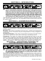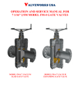
1
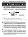
OM-263 230A
2013−06
Processes
Oxy-Fuel
Gas Regulation
Pressure Regulators
Specialty Gas
Inert
High Pressure
Liquid Cylinder
SAFETY MANUAL
File: Accessory
Form 4322 Rev 2013-06
TABLE OF CONTENTS
SECTION 1 − SAFETY PRECAUTIONS - READ BEFORE USING . . . . . . . . . . 1
1-1.
1-2.
Symbol Usage . . . . . . . . . . . . . . . . . . . . . . . . . . . . . . . . . . . . . . . . . . . . . . . . . . 1
Welding, Cutting, Brazing, Heating Hazards . . . . . . . . . . . . . . . . . . . . . . . . . 1
1-3.
1-4.
California Proposition 65 Warnings . . . . . . . . . . . . . . . . . . . . . . . . . . . . . . . . . 5
Principal Safety Standards . . . . . . . . . . . . . . . . . . . . . . . . . . . . . . . . . . . . . . . . 6
SECTION 2 − INTRODUCTION . . . . . . . . . . . . . . . . . . . . . . . . . . . . . . . . . . . . . . . . 7
SECTION 3 − HAZARDOUS EVENTS . . . . . . . . . . . . . . . . . . . . . . . . . . . . . . . . . . 7
SECTION 4 − HAZARDS OF RECOMPRESSING PURE OXYGEN . . . . . . . . . . 7
SECTION 5 − SPECIALTY GASES − SAFETY/TECHNICALINFORMATION . . 8
5-1.
5-2.
Information On Compressed Gases . . . . . . . . . . . . . . . . . . . . . . . . . . . . . . . . 8
Gas Classifications . . . . . . . . . . . . . . . . . . . . . . . . . . . . . . . . . . . . . . . . . . . . . . 8
SECTION 6 − PRE-INSTALLATION PROCEDURES: REGULATORS . . . . . . . 10
SECTION 7 − INSTALLATION AND OPERATION . . . . . . . . . . . . . . . . . . . . . . . . 11
SECTION 8 − SYSTEM SHUTDOWN . . . . . . . . . . . . . . . . . . . . . . . . . . . . . . . . . . 12
SECTION 9 − PERFORMANCE CHARACTERISTICS . . . . . . . . . . . . . . . . . . . . 12
SECTION 10 − CARE AND MAINTENANCE . . . . . . . . . . . . . . . . . . . . . . . . . . . . 13
WARRANTY
SECTION 1 − SAFETY PRECAUTIONS READ BEFORE USING
OXY FUEL 2013-06
Protect yourself and others from injury — read, follow, and
save these important safety precautions and operating instructions.
1-1. Symbol Usage
DANGER! − Indicates a hazardous situation which, if not
avoided, will result in death or serious injury. The possible
hazards are shown in the adjoining symbols or explained
in the text.
Indicates a hazardous situation which, if not avoided,
could result in death or serious injury. The possible hazards are shown in the adjoining symbols or explained in
the text.
NOTICE − Indicates statements not related to personal injury.
. Indicates special instructions.
This group of symbols means
Warning! Watch Out! ELECTRIC
SHOCK, MOVING PARTS, and
HOT PARTS hazards. Consult
symbols and related instructions below for necessary actions to avoid
the hazards.
1-2. Welding, Cutting, Brazing, Heating Hazards
The symbols shown below are used throughout this manual
to call attention to and identify possible hazards. When you
see the symbol, watch out, and follow the related instructions
to avoid the hazard. The safety information given below is
only a summary of the more complete safety information
found in the Safety Standards listed in Section 1-4. Read and
follow all Safety Standards.
Only qualified persons should install, operate, maintain, and
repair this equipment.
During operation, keep everybody, especially children, away.
Do not use this equipment unless you are trained in its proper
use or are under competent supervision. Follow the procedures described in this booklet every time you use the equipment. Failure to follow these instructions may cause fire, explosion, asphyxiation, property damage, or personal injury.
This equipment must be used in accordance with all Federal,
State, and local regulations as well as DOT (Department of
Transportation) and CGA (Compressed Gas Association) regulations. Contact your gas supplier for more information on
the proper use of compressed gases.
. In this document, the phrase “welding and cutting” also refers to other oxy-fuel operations like brazing and heating.
OM-263 230 Page 1
READ INSTRUCTIONS.
S Read and follow all labels and the Owner’s Manual carefully be-
fore installing, operating, or servicing equipment. Read the safety
information at the beginning of the manual and in each section.
S Use only genuine replacement parts from the manufacturer.
S Perform maintenance and service according to the Owner’s
Manuals, industry standards, and national, state, and local codes.
HOT PARTS can burn.
S Do not touch hot parts bare handed.
S Allow cooling period before working on equipment.
S To handle hot parts, use proper tools and/or wear heavy, insulated welding gloves and clothing to prevent burns.
FUMES AND GASES can be hazardous.
Welding and cutting produces fumes and gases. Breathing these
fumes and gases can be hazardous to your health.
D Keep your head out of the fumes. Do not breathe the fumes.
D If inside, ventilate the area and/or use local forced ventilation at
the flame to remove welding and cutting fumes and gases. Some
gases (natural gas and acetylene) are lighter than air and will collect in high areas. Other gases (propane and butane) are heavier
than air and will collect in low areas. Heavier-than-air gases are
more difficult to diffuse and are more likely to accumulate.
D If ventilation is poor, wear an approved air-supplied respirator.
D Read and understand the Material Safety Data Sheets (MSDSs)
and the manufacturer’s instructions for metals, consumables,
coatings, cleaners, and degreasers.
D Work in a confined space only if it is well ventilated, or while
wearing an air-supplied respirator. Always have a trained watchperson nearby. Welding and cutting fumes and gases can displace air and lower the oxygen level, causing injury or death. Be
sure the breathing air is safe. Test atmospheres in confined areas
for explosive and toxic gases before using oxy-fuel equipment.
D Do not weld or cut in locations near degreasing, cleaning, or
spraying operations. The heat from welding or cutting flame can
react with vapors to form highly toxic and irritating gases.
D Do not weld or cut on coated metals, such as galvanized, lead, or
cadmium-plated steel unless the coating is removed from the affected area, the area is well ventilated, and while wearing an airsupplied respirator. The coatings and any metals containing
these elements can give off toxic fumes if welded or cut.
D Do not weld or cut on sealed air conditioning or refrigeration systems unless all refrigerants have been removed from the system.
BUILDUP OF GAS can injure or kill.
D Shut off compressed gas supply when not in use.
D Always ventilate confined spaces or use approved air-supplied
respirator.
OM-263 230 Page 2
LIGHT RAYS can burn eyes and skin.
Light rays from the welding and cutting process produce intense visible
and invisible (ultraviolet and infrared) rays that can burn eyes and skin.
Sparks fly off from the weld.
D Wear approved face protection fitted with a proper shade of filter
lenses to protect your face and eyes from light rays and sparks
when welding, cutting, or watching (see ANSI Z49.1 and Z87.1
listed in Safety Standards).
D Wear welding goggles, or wear welding helmet/welding faceshield over approved goggles/safety glasses with side shields.
D Use protective screens or barriers to protect others from flash,
glare and sparks; warn others not to watch the welding or cutting.
D Wear protective clothing made from durable, flame-resistant
material (leather, heavy cotton, or wool) and foot protection.
WELDING AND CUTTING can cause
fire or explosion.
Welding and cutting on closed containers, such as tanks, drums, or
pipes, can cause them to blow up. Sparks can fly off from the welding or
cutting operations. The flying sparks, hot workpiece, and hot equipment
can cause fires and burns. Check and be sure the area is safe before
doing any welding or cutting.
D Do not use this welding and cutting equipment with gases and
D
D
pressures other than those for which it is intended. Oxygen is not
flammable; however, the presence of pure oxygen will drastically
increase the speed and force with which burning takes place. Oxygen must never be allowed to contact grease, oil, or other petroleum-based substances; therefore, be sure there is no oil or grease
on the regulator, cylinder, valves, or equipment. Do not use petroleum-based pipe sealants. Do not use or store near excessive heat
(above 125° F/51.5° C) or open flame. Do not refer to oxygen as air
and do not use oxygen as a substitute for compressed air. Do not
use oxygen to clean clothes or work area, for ventilation, or to operate pneumatic tools. Open oxygen cylinder valves slowly. Be sure
regulator adjusting handle is in the full out (off) position before
opening oxygen cylinder valve.
Inspect all equipment before use. Do not use damaged, defective,
or improperly adjusted welding and cutting equipment. Make sure
levers and valves work properly, threads on equipment are clean
(no grease or oil) and not deformed, gauges are intact and easy to
read, regulator is clean and free of oil or dirt, and fittings are properly sized for the cylinder. Make sure hoses are clean (no grease or
oil) and ferrules are properly installed so the fitting does not slip inside the hose. Be sure all connections are tight.
It is recommended that a reverse-flow check valve or a flashback arrestor be installed between the torch handle and the regulator. Check
valves do not prevent the propagation of a flame upstream (flashback) but are designed to prevent the unintentional backflow of gases
into the cutting attachment, torch, hoses, or regulator which could
cause an explosion or fire. A flashback arrestor can be installed on the
torch handle instead of a check valve. Miller flashback arrestors have
a reverse flow check valve and prevent the propagation of a flame upstream. If a flashback arrestor is installed, a check valve is not necessary. Using a flashback arrestor and a check valve may reduce gas
flow and affect torch operation. To help prevent the reverse flow of
gases, be sure the cylinders contain enough gas to complete the
work.
OM-263 230 Page 3
D Perform work only in an area with a fireproof floor (concrete). Do
not heat concrete because it may expand and explode violently.
D Perform work on a fireproof surface. Use heat resistant shields to
protect nearby walls and flooring.
D Do not use if grease or oil is present on equipment or if equipment is
D
D
D
D
D
D
D
D
D
D
D
D
D
D
D
D
D
D
D
D
D
D
damaged. Have equipment cleaned/repaired by a qualified person.
Do not open a cylinder valve quickly or the regulator may be damaged and cause a fire.
Do not open acetylene cylinder valve more than 3/4 turn. (For all
gases except acetylene, open cylinder valve fully to backseal the
cylinder valve.) Keep cylinder wrench on the cylinder for quick
shut-off.
Do not slightly open or “crack” acetylene cylinder valve to blow
debris from the valve outlet. Remove the debris using nitrogen, air,
or a clean, oil-free rag.
Always purge gas from the system before lighting torch. Purge gas
in a well-ventilated area and away from flame or sparks.
Keep torch flame or sparks away from cylinder, regulator, and gas
hose.
Use only the gases recommended by the manufacturer of the
oxy-fuel equipment being used.
Never light a torch with matches or a lighter. Always use a striker.
Do not use acetylene above 15 psi (103 kPa) flowing. It is acceptable to use acetylene regulators that indicate a static pressure up
to 22 psi (151 kPa).
Check oxy-fuel system for leaks with an approved leak detection
solution or leak detector. Never test for gas leaks with a flame.
Remove all flammables within 35 ft (10.7 m) of the welding or cutting operation. If this is not possible, tightly cover them with approved covers.
Do not weld or cut where flying sparks can strike flammable
material.
Protect yourself and others from flying sparks and hot metal.
Be alert that welding and cutting sparks and hot materials from
welding and cutting can easily go through small cracks and openings to adjacent areas.
Watch for fire, and keep a fire extinguisher nearby.
Be aware that welding or cutting on a ceiling, floor, bulkhead, or
partition can cause fire on the hidden side.
Do not weld or cut on containers that have held combustibles, or on
closed containers such as tanks, drums, or pipes unless they are
properly prepared according to AWS F4.1 and AWS A6.0 (see
Safety Standards).
Do not weld or cut where the atmosphere may contain flammable
dust, gas, or liquid vapors (such as gasoline).
Wear oil-free protective garments such as leather gloves, heavy
shirt, cuffless trousers, high shoes, and a cap.
Do not use fuel gases to clean clothes or work area.
Remove any combustibles, such as a butane lighter or matches,
from your person before doing any welding or cutting.
After completion of work, inspect area to ensure it is free of sparks,
glowing embers, and flames.
Follow requirements in OSHA 1910.252 (a) (2) (iv) and NFPA 51B
for hot work and have a fire watcher and extinguisher nearby.
OM-263 230 Page 4
CYLINDERS can explode if damaged.
Compressed gas cylinders contain gas under high pressure. If
damaged, a cylinder can explode. Since gas cylinders are normally part
of the welding or cutting process, be sure to treat them carefully.
D Protect compressed gas cylinders from excessive heat, mechanical shocks, physical damage, slag, open flames, and sparks.
D Install cylinders in an upright position by securing to a stationary
D
D
D
D
D
D
D
D
D
D
D
D
support or cylinder rack to prevent falling or tipping. Do not lay acetylene cylinders on their sides or acetone will flow out of the cylinder
and damage the equipment.
Keep cylinders away from any arc welding, cutting, or other electrical circuits.
Never drape a welding or cutting torch over a gas cylinder.
Never weld or cut on a pressurized cylinder − explosion will result.
Use only correct compressed gas cylinders, regulators, hoses, and
fittings designed for the specific application; maintain them and associated parts in good condition. Do not use compressed gas cylinder unless an approved gas regulator is attached to the gas valve.
Turn face away from valve outlet when opening cylinder valve. Do
not stand in front of or behind the regulator when opening the valve.
Keep protective cap in place over valve except when cylinder is in
use or connected for use.
Use the right equipment, correct procedures, and sufficient number of persons to lift and move cylinders.
Store compressed gas and oxygen cylinders in separate locations.
Store empty cylinders with valves closed and caps in place.
Do not modify or repair cylinders or valves. Store leaking acetylene
cylinders outdoors in a safe area. Identify leaking cylinders and return them to the supplier.
Dispose of used disposable cylinders according to the manufacturer’s recommendations. Do not throw cylinders in fire.
Follow instructions provided by the gas supplier and on compressed gas cylinders, associated equipment, and in Compressed
Gas Association (CGA) publication P-1 listed in Safety Standards.
FLYING METAL or DIRT can injure eyes.
S Welding, cutting, chipping, wire brushing, and grinding cause
sparks and flying metal.
S Wear welding goggles, or wear welding helmet/welding face-
shield over approved goggles/safety glasses with side shields.
1-3. California Proposition 65 Warnings
Welding or cutting equipment produces fumes or gases
which contain chemicals known to the State of California to
cause birth defects and, in some cases, cancer. (California
Health & Safety Code Section 25249.5 et seq.)
This product contains chemicals, including lead, known to
the state of California to cause cancer, birth defects, or other
reproductive harm. Wash hands after use.
OM-263 230 Page 5
1-4. Principal Safety Standards
Safety in Welding, Cutting, and Allied Processes, ANSI Standard Z49.1,
is available as a free download from the American Welding Society at
http://www.aws.org or purchased from Global Engineering Documents
(phone: 1-877-413-5184, website: www.global.ihs.com).
Safe Practices for the Preparation of Containers and Piping for Welding
and Cutting, American Welding Society Standard AWS F4.1, from Global
Engineering Documents (phone: 1-877-413-5184,
website: www.global.ihs.com).
Safe Practices for Welding and Cutting Containers that have Held Combustibles, American Welding Society Standard AWS A6.0, from Global
Engineering Documents (phone: 1-877-413-5184,
website: www.global.ihs.com).
Safe Handling of Compressed Gases in Cylinders, CGA Pamphlet P-1,
from Compressed Gas Association, 14501 George Carter Way, Suite
103, Chantilly, VA 20151 (phone: 703-788-2700,
website:www.cganet.com).
Acetylene, CGA Pamphlet G-1, from Compressed Gas Association,
14501 George Carter Way, Suite 103, Chantilly, VA 20151 (phone:
703-788-2700, website:www.cganet.com).
Safety in Welding, Cutting, and Allied Processes, CSA Standard
W117.2, from Canadian Standards Association, Standards Sales, 5060
Spectrum Way, Suite 100, Ontario, Canada L4W 5NS (phone:
800-463-6727, website: www.csa-international.org).
Safe Practice For Occupational And Educational Eye And Face Protection, ANSI Standard Z87.1, from American National Standards Institute,
25 West 43rd Street, New York, NY 10036 (phone: 212-642-4900, website: www.ansi.org).
Standard for Fire Prevention During Welding, Cutting, and Other Hot
Work, NFPA Standard 51B, from National Fire Protection Association,
Quincy, MA 02269 (phone: 1-800-344-3555, website: www.nfpa.org.)
OSHA, Occupational Safety and Health Standards for General Industry,
Title 29, Code of Federal Regulations (CFR), Part 1910, Subpart Q, and
Part 1926, Subpart J, from U.S. Government Printing Office, Superintendent of Documents, P.O. Box 371954, Pittsburgh, PA 15250-7954
(phone: 1-866-512-1800) (there are 10 OSHA Regional Offices—phone
for Region 5, Chicago, is 312-353-2220, website: www.osha.gov).
Applications Manual for the Revised NIOSH Lifting Equation, The National Institute for Occupational Safety and Health (NIOSH), 1600 Clifton
Rd, Atlanta, GA 30333 (phone: 1-800-232-4636,
website: www.cdc.gov/NIOSH).
Recommended Practices for Safe Oxyfuel Gas Cutting Torch Operation
C4.2/C4.2M, and Recommended Practices for Safe Oxyfuel Gas Heating Torch Operation C4.3/C4.3M from Global Engineering Documents
(phone: 1-877-413-5184, website: www.global.ihs.com).
OM-263 230 Page 6
SECTION 2 − INTRODUCTION
Inspect all equipment before use. Do not use damaged, defective, or improperly adjusted welding and cutting equipment.
Make sure levers and valves work properly, threads on equipment are clean (no grease or oil) and not deformed, gauges are
intact and easy to read, regulator is clean and free of oil or dirt,
and fittings are properly sized for the cylinder. Make sure
hoses are clean (no grease or oil) and ferrules are properly installed so the fitting does not slip inside the hose. Be sure all
connections are tight and there are no leaks in the system.
This booklet offers basic information regarding Smith pressure regulators. Given reasonable care, the regulators will provide trouble-free use
for many years.
SECTION 3 − HAZARDOUS EVENTS
The following events are very hazardous and can occur in any oxy-fuel
system. It is important to understand these hazards and know how to
prevent them.
Backfire: The return of the flame into the torch, usually accompanied by
a popping sound. The flame may be extinguished or it may re-appear at
the tip end.
Sustained Backfire: The return of the flame into the torch that continues to burn inside the torch with a hissing or squealing sound.
Flashback: The return of a flame into and through the torch or into the
hose. In some instances it can reach the regulator and even enter the cylinder. This is generally caused by the mixing of the oxygen and fuel gas in the
system. This is a very dangerous situation that can cause an explosion anywhere in the system. This is why purging is so important (see Section 7).
SECTION 4 − ASSOCIATED HAZARDS OF
RECOMPRESSING PURE OXYGEN
Open oxygen cylinder valves slowly. Opening an oxygen cylinder valve quickly can cause a fire or explosion. Be sure regulator adjusting handle is in the full out (off) position before opening an oxygen cylinder valve.
Recompressing high pressure oxygen in a low pressure cavity may create heat, resulting in combustion. For combustion to occur, oxygen, fuel,
and kindling temperatures must be present. All of these components
may be present when oxygen is recompressed by opening the tank valve
too quickly.
OM-263 230 Page 7
Oxygen: High purity oxygen accelerates the rate of combustion, increases heat output, and lowers the combustible point at which various
materials will burn.
Fuel: The fuel for combustion may be the regulator itself if enough heat is
produced to reach the kindling temperature of the regulator’s components.
Kindling Temperatures: Enough heat may be generated to ignite the
regulator components by the friction created when recompressing
high-pressure oxygen. This heat is known as the heat of recompression.
If an internal fire or flashback occurs (indicated by a whistling
sound or inverted flame), do the following:
D Turn off the torch oxygen valve immediately.
D Turn off the torch fuel valve.
D Turn off the oxygen cylinder valve.
D Turn off the fuel gas cylinder valve.
Do not relight the torch until the equipment has cooled to the touch and
the flashback cause has been determined and corrected.
SECTION 5 − SPECIALTY GASES − SAFETY AND
TECHNICAL INFORMATION
5-1. Information On Compressed Gases
. Contact your equipment supplier if you have a requirement or concern not covered in the booklet.
Gaseous and liquefied compressed gases may be categorized in the following classifications: flammable, oxidant, corrosive, inert, and toxic. Because these products may also be gases or liquids under pressure, the
hazards accompanying high pressure and low temperature may also be
present. The properties of a gas place it in one or a number of categories.
Certain basic rules must be followed in order to handle specialty gases
safely:
D
Know the hazards associated with the gas.
D
Know and understand the physical and chemical properties of the
gas.
D
Observe the necessary general precautions to be taken in the use
of specialty gases and the precautions specific to the gas.
In addition to the safe handling and storage procedures presented in this
section, the Compressed Gas Association and the Department of Transportation provide detailed gas safety information and regulations.
5-2. Gas Classifications
A.
Flammable
Flammable gases, when mixed with air, oxygen or other oxidants, burn or
explode upon ignition, depending upon the degree of confinement. Each
flammable gas has a gas−in−oxidant concentration range within the limits of which the gas may be ignited. Flammable ranges are expressed in
OM-263 230 Page 8
terms of air at ambient temperature and atmospheric pressure. A change
in temperature, pressure, or oxidant concentration may vary the
flammable range considerably. Mixtures above and below the flammable
range do not ignite. As a precaution in handling flammables, care must
be taken to eliminate all possible sources of ignition through the proper
design of facilities, the installation of approved electrical systems, and
the restriction of smoking and use of open flames. An explosimeter
should be used to determine the existence of a flammable mixture in areas of suspected leakage.
B.
Oxidant
A number of gases, although nonflammable, may initiate and support
combustion. Materials that burn in air burn more vigorously or even explosively in oxygen and certain other oxidants. All possible sources of ignition must be eliminated when handling oxidants. Oxidants must not be
stored with combustible materials. Oil, grease, or other readily combustible substances must not come in contact with cylinders or equipment used in oxidant service.
C.
Corrosive
Corrosives are those products that erode and deteriorate materials with
which they come in contact; such as metals, fabrics, and human tissue.
Some gases, although not corrosive in their anhydrous form, become
corrosive in the presence of water. Special care must be taken when selecting the proper construction materials for equipment in which corrosives are handled. Gases that do not cause deterioration but induce inflammation of human tissue are irritants. Inflammation of the tissue may
occur after immediate, prolonged or repeated contact with the irritant.
Protective clothing and equipment must be used to minimize exposure to
corrosive or irritating materials.
D.
Inert
Gases that at ordinary temperatures and pressure do not react with other
materials are classified as inert. If released in a confined area, inert gases may displace the oxygen content of the air below the level necessary
to sustain life. Asphyxiation, therefore, is the hazard associated with inert
products. Adequate ventilation and monitoring of the oxygen content of
confined areas minimizes the possibility of asphyxiation.
E.
Toxic
Toxic materials are those substances that may chemically produce injurious or lethal effects. The degree of toxicity and the effects vary with the
compound. Some gases are especially harmful because they do not provide adequate warning of their presence (by color, odor, etc.) at low levels of concentration. Also, some products that are nontoxic in themselves may react with certain chemicals or decompose at elevated
temperatures to produce toxic materials. Adequate ventilation, protective clothing, and suitable breathing equipment must be used to minimize
exposure.
F.
High Pressure
Specialty gases are compressed to pressures up to 6000 psig (4137
kPa). A sudden release of pressure may cause serious damage to personnel and equipment by propelling a cylinder or whipping a line. Factors
that must be considered when choosing construction materials and designing gas−handling systems are the temperature, the pressure of the
gas, and the possibility of pressure buildup in the system.
OM-263 230 Page 9
SECTION 6 − PRE-INSTALLATION PROCEDURES:
REGULATORS
Do not use this equipment unless you are trained in its proper
use or are under competent supervision. Follow the procedures described in this booklet every time you use the equipment. Failure to follow these instructions may cause fire, explosion, asphyxiation, property damage, or personal injury.
This equipment must be used in accordance with all Federal,
State, and local regulations as well as DOT (Department of
Transportation) and CGA (Compressed Gas Association) regulations. Contact your gas supplier for more information on
the proper use of compressed gases.
1.
2.
3.
4.
5.
6.
7.
8.
9.
Regulators must be used only with the gases and pressures for
which they are designed. Consult a safety data sheet (SDS) for
gases used to determine compatibility of gases and regulator
components (available from your gas supplier).
Check the designed pressure rating of the regulator (labeled or
stamped on the regulator body) and the scale range of the pressure
gauges. The pressure ratings must be adequate for the cylinder
pressure and the operating pressure.
Verify the materials used in the construction of the regulator are
compatible with the intended gas service.
Verify the regulator inlet connection is compatible with the cylinder
outlet valve connections.
Install a check valve purge assembly and pressure relief devices in
the operating system as required.
Do not interchange pressure regulators or other equipment that
was used with different gases unless you are sure the gases are
compatible.
Do not use regulator equipment for oxygen service that has been in
other gas service.
If the regulator has an open port, that port must be assembled for its
intended use.
If gauges are used with the regulator and the regulator is UL listed,
the following requirements apply:
A. Gauges over 1,000 psi (6895 kPa) should be UL listed per UL
standard 404.
B. Gauges under 1,000 psi (6895 kPa) should be UL recognized
per UL standard 252.
Do not use pressure regulators in ambient temperatures below
−40˚F (−40˚C) or above 140˚F (60˚C).
OM-263 230 Page 10
SECTION 7 − INSTALLATION AND OPERATION
Inspect all equipment before use. Do not use damaged, defective, or improperly adjusted welding and cutting equipment.
Make sure levers and valves work properly, threads on equipment are clean (no grease or oil) and not deformed, gauges are
intact and easy to read, regulator is clean and free of oil or dirt,
and fittings are properly sized for the cylinder. Make sure
hoses are clean (no grease or oil). Be sure all connections are
tight and there are no leaks in the system.
Low Pressure Gauge
High Pressure Gauge
Regulator Bonnet
Inlet (Tail Piece)
Connection
Outlet Connection
1.
2.
3.
4.
5.
6.
7.
8.
Adjusting Handle
Attach the regulator to the cylinder valve and tighten firmly with a
wrench.
Connect the operating system to the regulator outlet.
Turn the regulator adjusting handle counterclockwise until the adjusting handle turns freely (no spring load) or until the adjusting handle is against the mechanical stop. (This allows the regulator valve
to close).
Close the regulator outlet valve (if used).
Do not stand in front of or behind the regulator when opening
the cylinder valve. Never open a cylinder valve suddenly as this
can damage a regulator or cause an oxygen regulator fire.
Slowly open the cylinder valve until the full cylinder pressure is indicated on the high pressure regulator gauge. Then, open the cylinder valve all the way. This high pressure gauge should read the
cylinder pressure. The delivery gauge should read zero (0).
With the valve at the outlet of the regulator closed and the adjusting
handle tension released, leave pressure on the inlet for 5–10 minutes. Delivery pressure gauge should not indicate any pressure increase. A pressure increase indicates gas leakage past the regulator valve seat.
Do not use the regulator if gas leakage occurs.
Turn the adjusting handle clockwise to set a normal delivery pressure.
Do not use the regulator if you are unable to attain a desired
pressure or the pressure continues to rise above the set point.
If the unit functioned properly in the previous step, close the cylinder valve and note the readings of both the inlet and delivery pressure gauges. After 5–10 minutes, a drop in the reading of either
gauge indicates a leak in the system.
OM-263 230 Page 11
Use an approved oil-free leak detection fluid to locate possible
leaks at the inlet, any threaded port, through the regulator diaphragm or through the outlet valve. PTFE tape is an acceptable pipe thread sealant. If other sealing materials are preferred, those materials must be compatible with the gas that is
being used in the system.
9. If a leak is indicated, relieve all pressures from the regulator and
retighten the connections.
Do not use the regulator if a leak continues or is found at the
diaphragm or outlet valve.
10. If the system is determined to be leak free, turn the adjusting handle
clockwise until the desired pressure setting is indicated on the delivery pressure gauge.
11. Open the outlet valve to purge the system. Adjust the regulator adjusting handle to obtain the desired pressure setting at the flow conditions.
NOTICE − A regulator is not intended to be used as a shut−off device.
Close the cylinder valve when system is not in use. Install a pressure relief device downstream of the regulator or outlet valve to protect the
process equipment if operating pressures rise.
SECTION 8 − SYSTEM SHUTDOWN
1.
2.
3.
4.
5.
6.
7.
Close the cylinder valve.
Release all gas from the regulator and/or system so that both
gauges read zero (0). If the gas is flammable, an oxidant, corrosive,
or toxic, take appropriate measures to render it harmless by employing a suitable disposable system before venting the gas to the
atmosphere.
Turn the adjusting handle counterclockwise until all spring load is
released or the adjusting handle reaches the mechanical stop.
Close the outlet valve.
Disconnect the regulator.
If the regulator is to remain out of service, protect the inlet and outlet
fittings from dirt, contamination or mechanical damage.
Replace the cylinder valve cap.
SECTION 9 − PERFORMANCE
CHARACTERISTICS
The following information is intended to help you determine if the regulator is performing properly.
A.
Indications Of Proper Performance
D
The delivery pressure drops when flow is started and/or increased.
OM-263 230 Page 12
D
The delivery pressure rises when flow is stopped. This difference in
delivery pressure between flow and no flow condition is called
“lockup.”
D
The delivery pressure of a single stage regulator increases as the
supply/cylinder pressure decays (as the cylinder is emptied). This
will not happen with a 2-stage regulator until the supply pressure
drops below the first-stage set pressure of 250 psig (1724 kPa).
The exception is 250 psig (1724 kPa) delivery range regulators,
which are set at 400 psig (2758 kPa).
B.
Indications Of Improper Performance
D
The delivery pressure continues to rise when flow is stopped (lock−
up) without a change in adjusting-handle position. This condition
indicates valve seat wear or contamination with foreign materials
(which allows gas to leak to the delivery side). This condition is referred to as “creep.” If this condition exists, remove regulator from
service and have it repaired or replaced.
D
A significant drop in delivery pressure during normal flow conditions indicates internal blockage. Check inlet connection filters for
contamination. If this condition exists, remove regulator from service and have it repaired or replaced.
SECTION 10 − CARE AND MAINTENANCE
Periodic inspection and maintenance of the pressure regulator
is essential for continued safe and satisfactory operation. The
frequency of servicing will depend on duty cycle and type of
gas.
Inspect regulator monthly. If the regulator is used under normal, non-corrosive conditions, perform annual maintenance (such as removing deposits left by gas and replacing any worn or damaged parts). Inspect and
maintain the regulator more frequently if the system is subject to a high
duty cycle or is used in corrosive conditions. Regulators requiring service
repair should be sent to your equipment supplier.
A.
Inspection
Follow these steps to inspect regulator:
1. Inspect gauges to assure they read zero (0) when all pressure is
released from the system.
2. With adjusting handle turned counterclockwise (to release all
spring tension), slowly open cylinder valve. The high pressure
gauge should read cylinder pressure and the delivery gauge should
read zero (0).
3. With valve at outlet of regulator closed and adjusting handle tension
released, leave pressure on inlet for 5–10 minutes. The delivery
pressure gauge should not indicate any pressure increase. A pressure increase indicates leakage past the regulator valve seat.
If leakage is indicated, remove regulator from service and have
it repaired or replaced.
4. Turn adjusting handle clockwise to set a nominal delivery pressure.
If you are unable to attain desired pressure setting or if delivery
pressure continues to rise above set point, remove regulator from
service and have it repaired or replaced.
OM-263 230 Page 13
5.
6.
If unit functions properly in the previous step, close cylinder valve
and note the readings of both the inlet and delivery pressure
gauges. After 5–10 minutes, a drop in reading of either gauge indicates a leak in the system.
Use an approved oil-free leak detection fluid to locate possible
leaks at the inlet, any threaded port, through the regulator diaphragm, or through the outlet valve. PTFE tape is an acceptable pipe thread sealant. If other sealing materials are preferred, those materials must be compatible with the gas that is
being used in the system.
If leak is at the inlet or at a threaded port, relieve all pressure from
the regulator and then tighten. if leak continues or is found at the
diaphragm and outlet valve, remove regulator from service and
have it repaired or replaced.
B.
Storage
1.
Regulators taken out of service for extended periods should receive proper care to extend their service life.
Regulators used in a non-corrosive gas service should be wiped
clean with a clean, dry, lint-free cloth and sealed in a plastic bag for
storage in a dry area at room temperature.
Regulators used in a corrosive gas service should be well flushed
with dry nitrogen and sealed in a plastic bag. Regulators used for
corrosive service may continue to corrode in storage after exposed
to atmospheric oxygen and moisture.
2.
3.
C.
Repair Service
Any regulator in need of service should be returned to your equipment
supplier for evaluation.
OM-263 230 Page 14
Effective July 1, 2013
(For Oxy-Fuel and Pressure Regulation Equipment
with a date code of BDG or newer)
This limited warranty supersedes all previous Miller warranties and is exclusive with no other guarantees or warranties expressed or implied.
LIMITED WARRANTY - Subject to the terms and conditions below, Miller
Electric Mfg. Co., Appleton, Wisconsin, warrants to its original retail purchaser that new Miller equipment sold after the effective date of this limited warranty is free of defects in material and workmanship at the time it is shipped by
Miller. THIS WARRANTY IS EXPRESSLY IN LIEU OF ALL OTHER WARRANTIES, EXPRESS OR IMPLIED, INCLUDING THE WARRANTIES OF
MERCHANTABILITY AND FITNESS. Within the warranty periods listed below, Miller will repair or replace any warranted parts or components that fail
due to such defects in material or workmanship. Miller must be notified in writing within thirty (30) days of such defect or failure, at which time Miller will provide instructions on the warranty claim procedures to be followed. Miller shall
honor warranty claims on warranted equipment listed below in the event of
such a failure within the warranty time periods. All warranty time periods start
on the delivery date of the equipment to the original end-user purchaser, and
not to exceed one year after the equipment is shipped to a North American
distributor or eighteen months after the equipment is shipped to an International distributor.
1. Lifetime Warranty – Parts and Labor
*
Torch Handles, Cutting Attachments, Straight Cutting Torches
and Machine Torches stamped with a “LIFETIME” inscription. The
use of tips other than genuine Miller tips may void the lifetime warranty.
2. 3 Years – Parts and Labor
*
Toughcut Outfits, Series 30, 32, 35, 36, 40, 46 Regulators, and all
Flowmeters, Flow Gauges, and Flowmeter Regulators
3. 2 Years – Parts and Labor
*
Series 250, 820, and Smith-Branded Specialty Gas Regulators
4. 1 Year – Parts and Labor
*
Gas Axe Cutting Torches, HVAC/Purge Regulators, 3-Stage Nitrogen Low-Pressure Blanketing Regulators, Gas Savers, Gas
Mixers, and all other Oxy-Fuel Products
*
SMITH BRANDED PRODUCTS
The Little Torch, Quickbraze Torch, Handi-Heet/Silver Smith Torch
5. 90 Days – Parts and Labor
*
Corrosive Service Regulators
Miller’s True Blue) Limited Warranty shall not apply to:
1.
Consumable components; oxy-fuel cutting, welding, and heating tips,
or parts that fail due to normal wear.
2. Items furnished by Miller, but manufactured by others. These items are
covered by the manufacturer’s warranty, if any.
3. Equipment that has been modified by any party other than Miller, or
equipment that has been improperly installed, improperly operated or
misused based upon industry standards, or equipment which has not
had reasonable and necessary maintenance, or equipment which has
been used for operation outside of the specifications for the equipment.
MILLER PRODUCTS ARE INTENDED FOR PURCHASE AND USE BY
COMMERCIAL/INDUSTRIAL USERS AND PERSONS TRAINED AND EXPERIENCED IN THE USE AND MAINTENANCE OF WELDING EQUIPMENT. In the event of a warranty claim covered by this warranty, the exclusive
remedies shall be, at Miller’s option: (1) repair; or (2) replacement; or, where
OM-263 230 Page 15
authorized in writing by Miller in appropriate cases, (3) the reasonable cost of
repair or replacement at an authorized Miller service station; or (4) payment of
or credit for the purchase price (less reasonable depreciation based upon actual use) upon return of the goods at customer’s risk and expense. Miller’s
option of repair or replacement will be F.O.B., Factory at Appleton, Wisconsin,
or F.O.B. at a Miller authorized service facility as determined by Miller. Therefore no compensation or reimbursement for transportation costs of any kind
will be allowed. TO THE EXTENT PERMITTED BY LAW, THE REMEDIES
PROVIDED HEREIN ARE THE SOLE AND EXCLUSIVE REMEDIES. IN NO
EVENT SHALL MILLER BE LIABLE FOR DIRECT, INDIRECT, SPECIAL, INCIDENTAL OR CONSEQUENTIAL DAMAGES (INCLUDING LOSS OF
PROFIT), WHETHER BASED ON CONTRACT, TORT OR ANY OTHER LEGAL THEORY. ANY EXPRESS WARRANTY NOT PROVIDED HEREIN
AND ANY IMPLIED WARRANTY, GUARANTY OR REPRESENTATION AS
TO PERFORMANCE, AND ANY REMEDY FOR BREACH OF CONTRACT
TORT OR ANY OTHER LEGAL THEORY WHICH, BUT FOR THIS PROVISION, MIGHT ARISE BY IMPLICATION, OPERATION OF LAW, CUSTOM
OF TRADE OR COURSE OF DEALING, INCLUDING ANY IMPLIED WARRANTY OF MERCHANTABILITY OR FITNESS FOR PARTICULAR PURPOSE, WITH RESPECT TO ANY AND ALL EQUIPMENT FURNISHED BY
MILLER IS EXCLUDED AND DISCLAIMED BY MILLER.
Some states in the U.S.A. do not allow limitations of how long an implied warranty lasts, or the exclusion of incidental, indirect, special or consequential
damages, so the above limitation or exclusion may not apply to you. This warranty provides specific legal rights, and other rights may be available, but may
vary from state to state. In Canada, legislation in some provinces provides for
certain additional warranties or remedies other than as stated herein, and to
the extent that they may not be waived, the limitations and exclusions set out
above may not apply. This Limited Warranty provides specific legal rights,
and other rights may be available, but may vary from province to province.
Mil oxy-fuel warr 2013-05
OM-263 230 Page 16
Notes
OM-263 230 Page 17
Miller Electric Mfg. Co.
An Illinois Tool Works Company
1635 West Spencer Street
Appleton, WI 54914 USA
International Headquarters−USA
USA Phone: 920-735-4505 Auto-Attended
USA & Canada FAX: 920-735-4134
International FAX: 920-735-4125
For International Locations Visit
www.MillerWelds.com
ORIGINAL INSTRUCTIONS − PRINTED IN USA
E2013 Miller Electric Mfg. Co. 2013−01