1
Key Voice
Voice Processing
.
SYSTEM
INSTALLATION
AND
MAINTENANCE
Everything Your Business Calls For
NOTICE
NOTICE TO END USER: CAREFULLY READ THE FOLLOWING TERMS AND CONDITIONS. USE
OF THE SOFTWARE CONTAINED IN THIS PACKAGE CONSTITUTES YOUR ACCEPTANCE OF
THESE TERMS AND CONDITIONS AND AGREEMENT TO ABIDE BY THEM.
If you do not agree with the terms and conditions of this Agreement, return the package and its entire
contents to the location where you obtained it for a refund.
In return for acquiring a license to use the Key Voice Technologies Inc. software and documentation
contained in this package ("the Software"), and for acquiring the accompanying documentation, you, the
original purchaser ("You"), agree as follows:
1.
License Grant: You are granted a nonexclusive, personal license to: (a) use the Software on a single
personal computer system (b) copy the Software solely for the purpose of installing it on your computer
and for backup and archival storage. You may not transfer, sell, lease or distribute copies of the
Software to others. You may assign your rights under this Agreement to a third party provided the
third party agrees in writing to be bound to the terms of this Agreement and you transfer all copies of
the Software to the third party or destroy any copies not transferred. Any other attempt to sublicense,
assign or transfer any of the rights, duties or obligations hereunder is void.
2.
No Other Rights: You acknowledge that the Software is copyrighted and is proprietary. The license
granted above is not a sale of the Software, and except as stated above, this Agreement does not give
you any rights to patent, copyright, trade secrets, trademarks or any other rights or licenses with respect
to the Software. You agree to hold the Software in confidence and to take reasonable steps to prevent
unauthorized copying or distribution.
3.
No Modification or Reverse Compilation: YOU MAY NOT MODIFY, ALTER, TRANSLATE,
DISASSEMBLE OR DECOMPILE THE SOFTWARE OR DOCUMENTATION OR ANY COPY, IN
WHOLE OR IN PART.
4.
Limited Warranty: Key Voice Technologies, Inc. warrants that the original diskettes are free from
defects in material and workmanship, assuming normal use, for a period of ninety (90) days from the
date of purchase. If a defect occurs during this period, you may return your faulty disk along with a
dated proof of purchase; it will be replaced free of charge.
EXCEPT FOR THE EXPRESS WARRANTY OF THE ORIGINAL DISKETTES SET FORTH ABOVE,
NO OTHER WARRANTIES ARE GRANTED, EXPRESS OR IMPLIED, BY STATUTE OR
OTHERWISE, REGARDING THE DISKS AND RELATED MATERIALS, THEIR FITNESS FOR ANY
PURPOSE, THEIR QUALITY, THEIR MERCHANTABILITY, OR BOTH.
THE LIABILITY UNDER THE WARRANTY SET FORTH ABOVE SHALL BE LIMITED TO THE
AMOUNT PAID BY THE CUSTOMER FOR THE PRODUCT. IN NO EVENT SHALL THE
MANUFACTURER OR DISTRIBUTORS BE LIABLE FOR ANY SPECIAL, CONSEQUENTIAL, OR
OTHER DAMAGES FOR BREACH OF WARRANTY.
Information in product documentation is subject to change without notice, and does not represent a
commitment on the part of Key Voice Technologies Inc. No part of Key Voice manuals may be reproduced
or transmitted in any form or by any means, electronic or mechanical, including photocopying, for any
purpose other than the purchaser's personal use, without the written permission of Key Voice Technologies,
Inc. Products mentioned in this documentation that are not manufactured by Key Voice Technologies, Inc.
may be trademarks or registered trademarks of their respective manufacturers.
© Copyright Key Voice Technologies, Inc., 1991-1998.
All rights reserved.
LIMITED WARRANTY
The initial hardware and software of all Key Voice Technologies, Inc. (“Key Voice”) products
accompanying this installation manual shall be referred to collectively herein as the “Product”. Non-Key
Voice products are warranted solely by the manufacturer in accordance with the manufacturer’s warranty,
and are sold by Key Voice “as is”. Key Voice warrants, to its purchaser, its authorized dealers and the end
users of the Product, that, under normal operating conditions, (a) the Product hardware (except for fuses,
lamps and other consumables) and the medium on which the Product software is contained will be free from
defects in material and workmanship, and (b) the Product software will perform substantially in accordance
with the specifications set out in the user guide accompanying the Product which is prepared by Key Voice,
in each case for a period of one year, measured from the manufacturing date stamped on the Product
hardware or software, as the case may be, provided however, development products, i.e., products which
have not yet been approved by Key Voice for production, are sold pursuant to Key Voice’s field trial
agreement and are warranted as set out therein. Key Voice’s sole obligation under this warranty or under
any other legal obligation with respect to the Product is to repair or replace, at its option, the Product at its
Sarasota, Florida, headquarters, free of charge, if the Product is deemed defective by Key Voice during the
warranty period, with refurbished or new equipment or parts, at Key Voice’s option, when the Product is
returned to Key Voice, freight or postage prepaid, during the warranty period, provided however, if Key
Voice is not able, using reasonable efforts, to cure or correct a defect, Key Voice’s sole obligation shall
then be to refund (or cause to be refunded) an equitable portion of the price Key Voice was paid for the
Product. This warranty does not apply if, in the sole judgment of Key Voice, the Product, or any part(s) or
component(s) thereof, have been improperly installed or installed or used in combination or in assembly
with hardware or software not supplied by Key Voice and which are not compatible with the Product or
which are of inferior quality, design or performance, or the Product, or any part(s) or component(s) thereof,
have been improperly handled, misused, abused, altered, tampered with, accidentally damaged, or damaged
or malfunction or fail to function due to neglect, negligence, contamination (by liquid or otherwise) or as a
result of any other causes beyond Key Voice’s reasonable control, including extraordinary wear and tear
and acts of God such as fire, flood, water, or lightning or other incidence of excessive or insufficient voltage
or failure to follow instructions. Repair, wiring, or alteration of the Product other than as specifically
authorized by Key Voice or its authorized repair agent is prohibited and will void this warranty. This
warranty does not cover costs associated with installation, removal, or reinstallation of the Product. Key
Voice does not warrant that the Product is compatible with all telephone or switching systems or that the
Product is invulnerable or immune from unauthorized or fraudulent use, or unaccounted for access to the
Product. THIS WARRANTY IS EXCLUSIVE, BEING IN LIEU OF ALL OTHER WARRANTIES
EXPRESS OR IMPLIED, INCLUDING, BUT NOT LIMITED TO, ANY IMPLIED WARRANTY OF
MERCHANTABILITY OR FITNESS FOR A PARTICULAR PURPOSE.
LIMITATION OF LIABILITY
WITHOUT EXPANDING UPON THE FOREGOING WARRANTY, THE MAXIMUM LIABILITY OF
KEY VOICE UNDER ANY WARRANTY, STATUTORY, EXPRESS OR IMPLIED, IS LIMITED TO
THE PURCHASE PRICE OF THE PRODUCT. KEY VOICE SHALL HAVE NO RESPONSIBILITY
FOR DAMAGE TO PROPERTY OR ANY OTHER LOSS OR INJURY, INCLUDING
CONSEQUENTIAL, INCIDENTAL, OR INDIRECT DAMAGES, SUCH AS LOSS OF PROFITS OR
LOSS OF BUSINESS INFORMATION, DAMAGES DUE TO BUSINESS INTERRUPTION OR ANY
OTHER PECUNIARY LOSS, EVEN IF KEY VOICE HAS BEEN ADVISED OF THE POSSIBILITY OF
SUCH DAMAGES, OR PUNITIVE DAMAGES, RESULTING FROM THE PURCHASE, POSSESSION,
INSTALLATION, OPERATION, REPAIR, USE OF PURCHASE, POSSESSION, INSTALLATION,
OPERATION, REPAIR, USE OF OR INABILITY TO USE, THE PRODUCT, OR THE
UNAUTHORIZED OR THE FRAUDULENT USE OF, OR UNACCCOUNTED FOR ACCESS TO, THE
PRODUCT, ALL SUCH CLAIMS BEING HEREBY EXPRESSLY WAIVED. THE PURCHASER’S
EXCLUSIVE WARRANTY AND REMEDY SHALL BE ONLY AS STATED HEREIN.
This warranty gives you specific legal rights and you may also have other rights which may vary from state
to state. Some states do not allow limitation on how long an implied warranty lasts or the exclusion or
limitation of incidental or consequential damages, so the above limitations may not apply to you. If the
Magnuson Moss Act should be held to apply to the sale of the Product by a court of competent jurisdiction,
the implied warranty of fitness for a particular purpose shall extend for one year from the date of
manufacture. No Key Voice dealer nor any other person or entity other than Key Voice may extend or
modify this warranty, and no such modification or extension shall be effective unless it is in writing.
INSTALLATION AND MAINTENANCE MANUAL 9.0 VER. 1.A
1. Overview
1.1 What Does the VP System Do?
In its simplest form, the VP system acts like a telephone receptionist. It answers incoming calls and
transfers them to the appropriate extension. If the called extension is not available (busy or no answer),
the VP system offers to take a message or try an alternative extension.
VP system functionality includes:
•
•
Automated attendant features
Voice mail features
These two functions work together to provide smooth call coverage for your application.
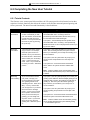
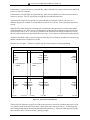
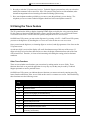
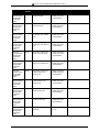
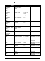
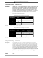
1.1.1 What is an Automated Attendant?
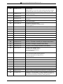
The VP system automated attendant features perform the tasks of a live attendant. The following table
illustrates how.
Live Attendant
VP System Automated Attendant
Answers an incoming call by lifting telephone.
Answers an incoming call by going “off-hook.”
Greets the caller with a phrase such as, "Welcome to
[XYZ Company]."
Greets the caller by playing a pre-recorded greeting
such as, "Welcome to [XYZ Company]."
Asks to whom the caller wishes to speak.
Plays a pre-recorded greeting that prompts the caller to
either dial the extension of the party they are trying to
reach or choose from a list of voiced options to route
the call to a specific department or group.
Listens to the caller's response.
Listens to the digits dialed by the caller.
Says, "Please hold."
Plays a pre-record phrase, "Please hold..."
Calls the required extension by hook-flashing and
dialing the extension number.
Calls the required extension by hook-flashing and
dialing the extension number.
Listens for busy tone, ring tone, answer, etc.
Listens for busy tone, ring tone, answer, etc.
If the extension is busy, offers to let the caller hold. If
the extension does not answer, offers to take a
message or try another extension.
If the extension is busy, plays a pre-recorded prompt
offering the option to hold. If the extension does not
answer, plays a pre-recorded prompt offering to take a
message or try another extension.
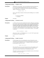
1.1.2 What is Voice Mail?
The term voice mail refers to systems that can record a voice message and treat it like a mail message.
In a typical office environment, the live attendant takes a message from a caller and writes it down on a
piece of paper. The attendant then places the slip in the recipient’s in-box or mailbox. The box owner
then retrieves and reads the message placed in the box.
1-1
INSTALLATION AND MAINTENANCE MANUAL 9.0 VER. 1.A
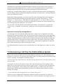
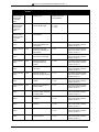
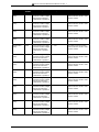
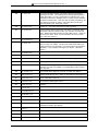
In contrast, the VP system records a message from a caller and places it in a voice mailbox. The mailbox
owner can later retrieve the message by calling into the VP system and listening to the recording. The
table below compares how the VP system processes voice messages compared to a live attendant.
Live Attendant
VP System Voice Mail
Attendant listens as the caller dictates his/her message, VP system records the message as the caller speaks.
writing it down on a piece of paper.
Attendant places the message slip in a mailbox
belonging to the recipient.
VP system stores the voice message electronically in
the recipient’s voice mailbox.
Attendant dials the code to turn on message waiting
lamp on the recipient's telephone.
VP system dials the code to turn on the message
waiting lamp on the recipient's telephone.
Recipient sees the message waiting lamp is on, and
retrieves message slips from the message mailbox.
Recipient sees the message waiting lamp is on and
dials the VP system to retrieve messages.
Recipient reads messages left on message slips.
VP system plays messages recorded by callers in the
voice mailbox.
1.2 Understanding the VP System Product Design
All VP systems are designed using the Box concept. A box contains a set of instructions that tells the
program what to do with a call it is handling. By setting up the system to send calls to different boxes
created on the system, you can have it effectively process calls—including playing certain prompts or
greetings to callers, collecting information and messages from callers, and routing calls to certain
extensions based on digits dialed by callers.
Note:
All VP system products use the same general software design, but each has different
limitations on the number of boxes you can set up on the system and whether you have
access to certain optional modules. Information provided in this manual is designed to
accommodate all VP system types. Therefore, certain sections and procedures may not
be applicable to certain VP system users. If you have questions regarding the availability
of a specific feature or option on a particular system, contact your sales representative.
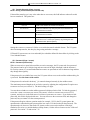
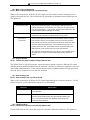
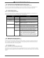
1.2.1 Understanding Box Types
Routing boxes are used to answer incoming calls, play a list of options to callers, and route calls to a
specific mailbox based on the digits dialed by the caller. The mailboxes transfer calls to their associated
extensions and store messages for system subscribers, and they can be set up to forward calls to another
phone or extension number, deliver messages to another phone or pager, play one of 10 pre-recorded
greetings to callers, screen calls, queue calls when the extension is busy, or record call conversations.
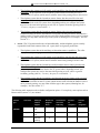
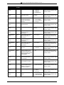
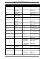
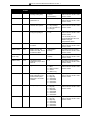
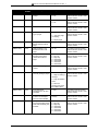
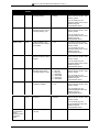
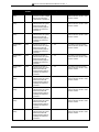
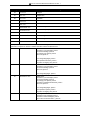
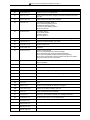
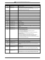
Routing boxes and mailboxes are the two core boxes used on VP systems. The following table identifies
other available box types and provides a brief synopsis of how each box is used on the VP system.
1-2
INSTALLATION AND MAINTENANCE MANUAL 9.0 VER. 1.A
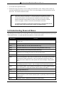
Box type
Function
Mailbox
Performs call transfers. Plays personal greetings. Takes messages.
Activates pagers. Delivers messages internally or externally. Activates
message waiting lights.
Question box
Performs question/answer sessions. Records caller responses verbally
or in a text file.
Routing box
Offers menu choices, and routes calls. Plays system recordings.
Group box
Houses a list of mailboxes, allows users to easily send one message to
more than one mailbox owner.
Directory box
Allows callers to spell out (via their touch-tone dial-pad) the name of the
person to whom they want to speak, or to simply listen to the entire
directory listing.
ACD box
Searches a list of extensions for one that is not busy, then transfers the
call to that extension.
Account Number
box
Asks the caller to enter an account number (or phone number, Zip Code,
etc.), which is tagged to the call and used for other functions.
Each of these boxes is described in detail in section 5.
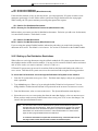
Note:
No matter where you are in the system, you can get help by pressing the <F1> key from
VP system screens.
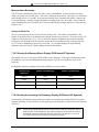
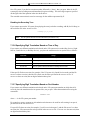
1.2.2 Understanding the Default Database
The VP system contains a default database with a setup configuration that allows the system to
efficiently perform fundamental call processing tasks with minimal system adjustments by the installing
technician. This default database configuration includes 2 pre-defined classes of service (0 and 7), 1
supervisor mailbox (mailbox 70), and 3 Routing boxes—800, 801, 821.
As you proceed through these setup instructions, you will make adjustments to specific information
relating to the default setup. As you make any changes, keep in mind that we urge you to maintain the
initial general configuration of Routing boxes 800, 801, and 821, Class of Service 7, and supervisor
mailbox 70. This configuration allows the VP system to efficiently perform fundamental call processing
tasks. Maintaining it helps both the installing technician and VP system technical support to efficiently
service the system and resolve any call processing issues. For these reasons we urge you not to deviate
from this general system setup default configuration.
The information below highlights the set up configuration provided with the default database included on
the VP system. Refer to this information as needed while you customize the VP system for the
customer’s specific application. For additional information on Routing box, mailbox, and prototype
mailbox functionality, see section 5.5. For additional information on Class of Service setup, see section
4.10.
1-3
INSTALLATION AND MAINTENANCE MANUAL 9.0 VER. 1.A
Note:
Though you may make adjustments to specific information relating to this default setup,
you are urged to maintain the general configuration of Routing boxes 800, 801, and 821,
Class of Service 7, and supervisor mailbox 70. This configuration allows the VP system
to efficiently perform fundamental call processing tasks. Maintaining it helps both the
installing technician and VP system technical support to efficiently service the system and
resolve any call processing issues.
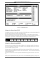
Technician Password:
1234
Business Hours (specified on the BUSINESS HOURS screen):
8:00 AM - 5:00 PM
Routing Box 800:
Answers all incoming calls during day/lunch hours (specified on the BUSINESS HOURS screen)
Owned by mailbox 70
Routing Box 801:
Answers all incoming calls during non-day/lunch hours (specified on the BUSINESS HOURS screen)
Owned by mailbox 70
Routing Box 821:
Routes calls that have already passed through Routing box 800 or 801
Owned by mailbox 70
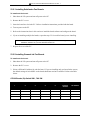
Class of Service 0:
Set up with the following parameter settings (for information on specific parameter fields, refer to
section 4.10:
MAXIMUM NUMBER OF GREETINGS: 10
MAXIMUM NUMBER OF MESSAGES: 200
MAXIMUM GREETING LENGTH (SECS): 60
MAXIMUM MESSAGE LENGTH (SECS) 60
AUTO-DELETE OLD MESSAGES AFTER 30 DAYS.
AUTO DELETE NEW MESSAGES AFTER 99 DAYS.
SUPERVISOR STATUS? No
ACCESS TO GROUP-BOXES? Yes
DIAL-OUT ALLOWED? No
ACCESS TO P.A.? Yes
PLAY MENU AFTER GREETING? No
ALLOWED TO RECEIVE FAXMAIL? No
OPERATOR BOX (DAY): 888 (NIGHT): 888
WHEN EXITING OPEN MAILBOX, GO TO BOX: 821
MAX LINES ALLOWED TO HOLD FOR ONE BOX: 2
WHILE IN QUEUE, SAY POSITION IN LINE? No
TRY EXTENSION 3 TIMES BEFORE GOING BACK TO CALLER
RESTRICTED DIGITS: [None]
Class of Service 7:
Set up with the Class of Service 0 options, but with SUPERVISOR STATUS enabled
Extension Length:
3 digits
1-4
INSTALLATION AND MAINTENANCE MANUAL 9.0 VER. 1.A
Password Length:
4 digits
Default Passwords:
Equal the mailbox numbers
Mailbox 70:
Set up as the Supervisor mailbox with Class of Service 7
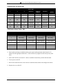
Prototype mailbox 9994 (characteristics are automatically assigned to all mailboxes created):
TRANSFER TYPE: Wait for Ring
CLASS OF SERVICE: 0
to: X (signifies the mailbox number)
CURRENTLY ENABLED: Yes
TRANSFER SCHEDULE: AlwaysPASSWORD: X (signifies the mailbox number) SEQUENCE TO TURN
ON/OFF MESSAGE WAITING LAMP: (set by Integration program)
AFTER PLAYING GREETING: Wait for digit
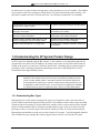
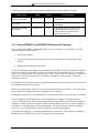
1.2.3 Understanding Product Differences
All VP system products use the same software base, but each has different limitations on the number of
boxes you can set up on the system and whether you have access to certain optional modules.
Information provided in this manual is designed to accommodate all VP system types. Therefore, certain
sections and procedures may not be applicable to certain VP system users. If you have questions
regarding the availability of a specific feature or option on a particular system, contact your sales
representative.
Also be advised that the NT-based VP systems offer users a graphical screen interface, which provides
slide bars, tabbed pages, buttons, and icons that are not available with other VP systems. For information
on navigating NT-based VP system screens using graphical screen elements such as tabbed pages and
buttons, consult a Microsoft NT or Windows user’s manual.
The functionality of system and box setup screens, fields on screens, and most configuration file
parameters is identical throughout the entire line of VP system products, including the NT-based
products. With the NT-based products, however, there are differences in the techniques you use to
access system and box setup screens and navigate through those screens. The NT-based VP systems
allow you to display multiple VP system windows simultaneously, for example, and to access some
screens from within others, whereas other VP systems do not. These differences equip NT-based system
users with additional navigational and display flexibility.
To ease dealer and technician transition to the NT-based VP systems, most screen and system navigation
techniques provided with other VP systems are also provided with the NT-based systems. You can, for
example, use the same function keys in both types of systems to navigate through program screens.
Because this manual is designed to accommodate all VP systems, it references wherever possible these
common navigational techniques in discussions and procedures. Keep in mind, therefore, that if you are
working with an NT-based VP system, you may choose to use navigational techniques other than those
documented here to access and work with VP system screens.
With this in mind, also be advised that you may choose to use Windows tools such as File Manager or
Explorer to complete tasks that are performed from a DOS prompt on other VP systems. Because NT-
1-5
INSTALLATION AND MAINTENANCE MANUAL 9.0 VER. 1.A
based system users can perform these tasks from a DOS prompt or using other techniques, for the sake of
simplicity, only the DOS prompt method is discussed in this manual.
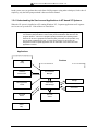
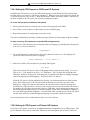
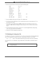
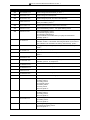
1.2.4 Understanding the Services and Applications in NT-based VP Systems
When the VP system is installed on a PC running Windows NT, 5 separate applications and 5 separate
services are set up on the PC. Each of these are listed below.
Note:
An application is a program launched by a user. Applications typically include a graphical
user interface (GUI) that allows a user to easily make modifications that affect how the
program operates. A service is a program typically launched by the operating system.
Services do not have a graphical user interface (GUI), and under normal operation, they
are not directly modified by the user. In some cases, however, a service may be
designed to monitor a specific application and use information a user enters onto that
application’s screens.
Applications
Services
PBX
Setup
Database
Administrator
KVT Database
Manager
Dialogic
Message Status
Viewer
KVT Voice
Mail Manager
GammaFax
Voice Mail
Viewer
KVT FTP
Server
Online
Help
1-6
INSTALLATION AND MAINTENANCE MANUAL 9.0 VER. 1.A
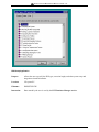
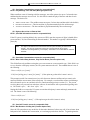
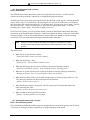
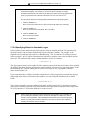
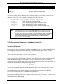
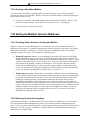
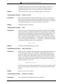
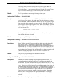
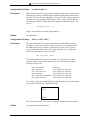
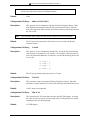
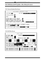
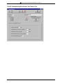
Understanding VP System NT Applications
The following illustration depicts an example of the VP system Key Voice applications menu that
displays on PCs running Windows NT-based VP systems.
Note that an additional application, PBX Setup, is also provided with NT-based VP systems. Because
the PBX Setup application should only be run the first time the system is set up, it is not included on the
applications menu.
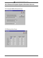
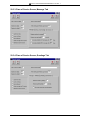
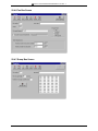
Database Administrator Application
Purpose:
Location:
Filename:
Interaction:
Allows the user to view and modify system and box setups.
VP system PC (but can be moved to another PC on the LAN).
DBA.EXE.
Data entered by the user is used by the KVT Database Manager service.
1-7
INSTALLATION AND MAINTENANCE MANUAL 9.0 VER. 1.A
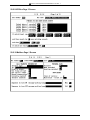
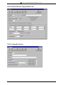
Message Status Viewer Application
Purpose:
Location:
Filename:
Interaction:
Allows the user to view the number of Old and New messages in mailboxes.
VP system PC (but can be moved to another PC on the LAN).
BOXDISPLAY.EXE.
Displays data stored in the KVT Database Manager service.
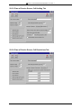
Voice Mail Viewer Application
Purpose:
Allows the user to view the status of the KVT Voice Mail Manager service, including
the current line activity, and the storage available. Also allows the user to enable or
disable a port on the system.
Location:
VP system PC (but can be moved to another PC on the LAN).
Filename:
VIEWER.EXE.
Interaction:
Displays data store in the KVT Voice Mail Manager service and provides port
enabling or disabling data to that service.
1-8
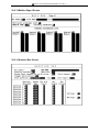
INSTALLATION AND MAINTENANCE MANUAL 9.0 VER. 1.A
Online Help Application
Purpose:
Provides online access to the information in the Installation and Maintenance manual.
Information provided covers installing, setting up, and working with the KVT system
using the system’s screens and telephone interface.
Location:
VP system PC (but can be moved to another PC on the LAN).
Filename:
DBA.HLP.
Interaction:
Online help can be run as an independent application on any computer running
Windows 95 or Windows NT. It is also accessible through the Voice Mail Viewer
application and the Database Administrator application.
1-9
INSTALLATION AND MAINTENANCE MANUAL 9.0 VER. 1.A
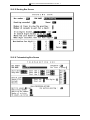
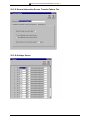
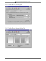
PBX Setup Application
Purpose:
Allows the user to specify the PBX type, extension length, and other system setup and
integration-related information.
Location:
VP system PC.
Filename:
PBXSETUP.EXE.
Interaction:
Data entered by the user is used by the KVT Database Manager service.
1-10
INSTALLATION AND MAINTENANCE MANUAL 9.0 VER. 1.A
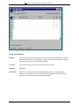
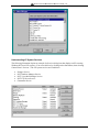
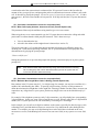
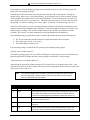
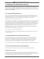
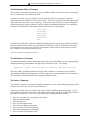
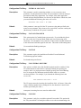
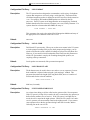
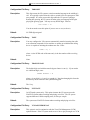
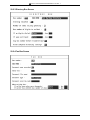
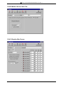
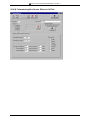
Understanding VP System Services
The following illustration depicts an example of a Services dialog box that displays on PCs running
Windows NT-based VP systems. (You access this box by clicking on the Start button, then selecting
Control Panel / Services.) The VP system services are listed below:
•
•
•
•
•
Dialogic Service
KVT Database Manager Service
KVT Voice Mail Manager Service
KVT FTP Server Service
GammaFax Service
1-11
INSTALLATION AND MAINTENANCE MANUAL 9.0 VER. 1.A
Dialogic Service
Purpose:
Location:
Filename:
Interaction:
Operates the voice boards.
VP system PC.
DLGC_SRV.EXE.
Exchanges data with other services, primarily the KVT Voice Mail Manager service.
KVT Database Manager Service
Purpose:
Location:
Filename:
Interaction:
Holds the system setup and box setup information.
VP system PC.
KVDBSERVER.EXE.
Exchanges data with other services, primarily providing data to the Database
Administrator application and the Message Status Viewer application.
KVT Voice Mail Manager Service
Purpose:
Location:
Filename:
Interaction:
Interacts with the GammaFax and Dialogic service hardware to process calls.
VP system PC.
VMSERVICE.EXE.
Exchanges data with other services, primarily providing data to the Voice Mail Viewer
application.
KVT FTP Server Service
Purpose:
Location:
Filename:
Interaction:
Communicates with client PCs running VCM and unified messaging features.
VP system PC.
KV_FTP_SERVICE.EXE.
Exchanges data with other services and with applications installed on client PCs
(application such as VCM, unified messaging, report generation programs, etc).
GammaFax Service
Purpose:
Location:
Filename:
Interaction:
Operates the fax boards.
VP system PC.
GFDCP.EXE.
Exchanges data with other services, primarily the KVT Voice Mail Manager service.
1-12
INSTALLATION AND MAINTENANCE MANUAL 9.0 VER. 1.A
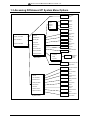
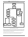
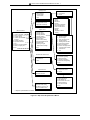
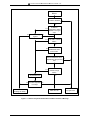
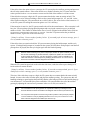
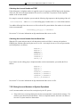
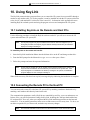
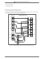
1.3 Accessing DOS-based VP System Menu Options
Line Status
screen
Mail Box
screen 1
Page
Page 2
Mail Box
screen 2
Page 3
Exit
Mail Box
screen 3
Display Line Status
Question Box
screen
Mail Box
Routing Box
screen
Question Box
Box Information
Routing Box
Group Box
screen
Group Box
System Information
Main menu
Directory Box
screen
Directory Box
ACD Box
ACD Box
screen
Account Number
Acct number Box
screen
Display Database
Optional Features
To screen
To file
Box menu
To printer
Database
Display
screen
Optional feature box
setup screen
General Information
screen
Line Information
screen
Business Hours
screen
General
Line Information
Holiday Schedule
screen
Business Hours
Holiday Schedule
Call Transfer
screen
Call Transfer
Technical
screen
Technical
Class of Service
Optional Features
Class of Service
screen
System menu
Optional Features
menu screen
1-13
INSTALLATION AND MAINTENANCE MANUAL 9.0 VER. 1.A
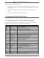
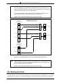
1.4 Accessing NT-based VP System Menu Options
Database
Display
screen
To screen
To file
To printer
Mail Box
screen
Question Box
screen
File
Routing Box
screen
Mail Box
Group Box
screen
Question Box
Boxes
Routing Box
System
Directory Box
screen
Group Box
ACD Box
screen
Directory Box
Diagnostics
Help
ACD Box
Acct Number box
screen
Account Number Box
Optional feature box setup
menu screen
Optional Features
Main menu bar
Boxes menu
General
screen
Line Information
screen
General
Business Hours
screen
Line Information
Business Hours
Holiday Schedule
screen
Holiday Schedule
Class of Service
Class of Service
screen
PBX Information
PBX Information
screen
Optional Features
Prompt Recorder
Optional feature setup
menu screen
System menu
Trace Setup
screen
Trace Setup
Custom Flags
Custom Flags
screen
Diagnostics menu
1-14
INSTALLATION AND MAINTENANCE MANUAL 9.0 VER. 1.A
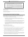
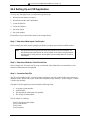
2. Preparing the System
2.1 Understanding Available System Setup Techniques
There are two techniques you can use to set up VP systems:
•
Use the program’s screen interface to run the System Setup utility then complete System
Information and Box Setup screens (you may need to attach a laptop to the VP system PC, if the
system does not have a monitor and/or a keyboard—procedures are provided in section 10)
•
Call into the VP system and use the teleparameter feature to run the System Setup utility then
enter parameter codes and corresponding values to set up system and box information
Technicians who have experience setting up VP systems may prefer to use the teleparameter feature to
quickly make modifications and get VP system up and running at the customer’s site. Detailed
instructions on using the teleparameter feature to complete system setup steps are provided in section 11.
Be advised that because the teleparameter setup technique involves inputting codes that represent system
parameters and corresponding values to which parameters are to be set, it is a bit more difficult to use
effectively if you are unfamiliar with setting up VP systems. For this reason, we recommend that
technicians unfamiliar with VP systems refrain from using the teleparameter feature and instead, use
instructions provided in the following sections to complete all necessary system setup steps through the
screen interface.
Note:
If you choose to set up the system using the teleparameter feature, be sure to first review
section 1, so you clearly understand the setup of the default database provided with the
VP system. For detailed information on using the teleparameter feature, see section 11.
Note that if you choose to initially set up the system using the screen interface (either directly of via a
laptop), you can later make additional modifications by simply calling into the VP system and using
options on the Supervisor menu (see section 7.11) or using the teleparameter feature (see section 11).
To install, set up, and maintain a VP voice processing system, you need the equipment listed below.
Equipment Needed
•
VP System Unit
Note:
•
If you are installing a VP system purchased as a kit (the software and boards are not preinstalled in the system), see section 21 for kit installation requirements and procedures.
Once you complete procedures provided in section 21 continue with information and
procedures provided here.
Portable Diskette Drive (only for systems without a diskette drive)
Should an unusual situation arise, it may be necessary for you to service VP systems that do not
include a diskette drive by attaching a portable diskette drive to the VP system unit. Therefore,
2-1
INSTALLATION AND MAINTENANCE MANUAL 9.0 VER. 1.A
we strongly recommended that technicians servicing VP units without diskette drives have access
to a portable diskette drive.
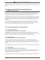
•
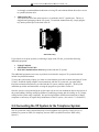
Authorization Key
VP systems only run if the authorization key is attached to the PC’s parallel port. This key is
shipped in the packaging with the VP system. To attach the authorization key, simply plug the
key into the parallel port in the back of the PC.
Authorization Key
If you choose to set up the system by connecting a laptop to the VP unit, you need the following
additional equipment:
•
•
•
Laptop Computer
Null Modem Serial Cable
KeyLink Communications Software (provided with the VP system)
This additional equipment is necessary to perform screen interface setups on VP systems that do not
include a keyboard and monitor.
To set up the system using a laptop, you must use a null modem serial cable to attach the laptop PC to the
VP unit. So that the laptop computer can communicate with the VP system unit, you must install
KeyLink communication software, provided with the VP system, onto the laptop PC. The KeyLink
installation procedure and instructions on using the program are provided in section 10.
Once the system is set up and tested, the system supervisor on-site can maintain the day-to-day aspects of
the system (adding, deleting, modifying mailboxes; modifying greetings and call routing; etc.) by simply
calling into the system using a telephone. No special teleparameter modification instructions or laptop
computers are necessary for regular daily maintenance of the VP system. (See section 7.11 for details.)
2.2 Connecting the VP System to the Telephone System
The VP system unit can be connected directly to local telephone lines, typically Centrex service, or
behind a key system or PBX. (For simplicity, the term PBX is used herein to mean “PBX or Key
System”).
2-2
INSTALLATION AND MAINTENANCE MANUAL 9.0 VER. 1.A
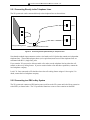
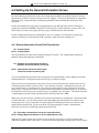
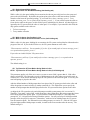
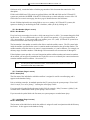
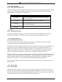
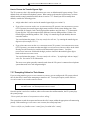
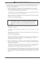
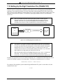
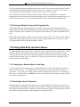
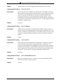
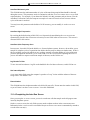
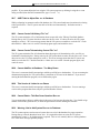
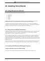
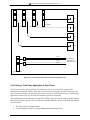
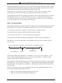
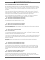
2.2.1 Connecting Directly to the Telephone Lines
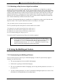
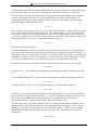
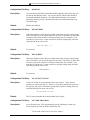
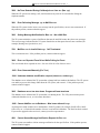
The VP system unit can be connected directly to the telephone lines as shown below.
Line 1
Line 2
Voice processing board
Radio Shack part number 279-402
Figure 2-1 Connecting the VP System Directly to Telephone Lines
Note that the modular input connectors on the voice boards are RJ-14 jacks that contain two independent
telephone lines. The modular adapter shown (or its equivalent) must be used if the telephone lines are
terminated with RJ-11 (single line) jacks.
If you want the VP system to be able to transfer calls, make sure the telephone line has either the calltransfer or three-way calling feature. If you are unsure whether a line has these capabilities, contact the
local telephone company.
Local C.O. lines connected to VP should not have the call-waiting feature assigned. Once again, if in
doubt, contact the local telephone company.
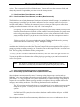
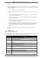
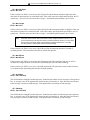
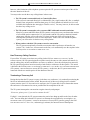
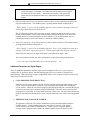
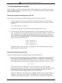
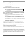
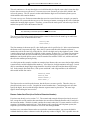
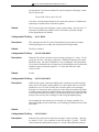
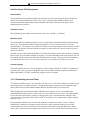
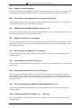
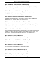
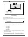
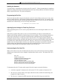
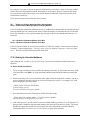
2.2.2 Connecting to a PBX or Key System
The VP system unit connects to PBX station ports (each line to the VP system unit looks like an extension
to the PBX), as shown below. The VP system thus functions as one or more extension on the PBX.
2-3
INSTALLATION AND MAINTENANCE MANUAL 9.0 VER. 1.A
Radio Shack
part number 279-402
Line 1
Ext A
CO 1
Ext B
Line 2
Ext C
Ext D
CO 2
Central
Office
PBX
Voice processing board
CO n
Line n
( ( ( (
Normal PBX extensions
Figure 2-2 Connecting the VP System Behind a Key-System or PBX
Note that the modular input connectors on the voice boards are RJ-14 jacks, which contain two
independent telephone lines. The modular adapter shown (or its equivalent) must be used if the PBX
extensions are terminated with RJ-11 (single line) jacks.
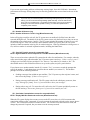
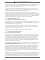
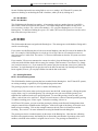
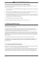
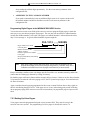
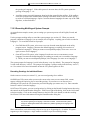
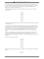
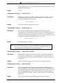
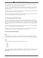
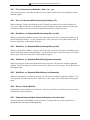
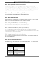
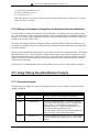
Each line to the VP system unit requires an industry-standard-telephone port on the PBX (this is also
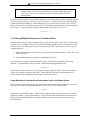
known by other names such as analog port, 2500 set interface, SLT port). Some telephone systems do
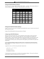
not provide single-line-telephone ports, and they require a special analog interface box between the PBX
and the voice mail system, as shown below. If in doubt, contact the local PBX manufacturer’s
representative.
Radio-shack part
number 279-402
ATI
Line 1
Ext A
CO 1
ATI
Ext B
CO 2
Line 2
PBX
Central
Office
CO n
Voice-processing board
Line n
( ( ( (
Normal PBX extensions
Figure 2-3 Connecting the VP system to a PBX via external Analog Telephone Interface (ATI) Equipment
2-4
INSTALLATION AND MAINTENANCE MANUAL 9.0 VER. 1.A
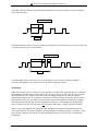
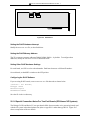
2.2.3 Connecting the Serial Cable Between the VP System and PBX
If you are establishing a serial integration, you must attach a serial cable between the VP system and the
PBX. The VP system unit is set up to use the COM 1 port to communicate with the phone system.
Therefore, you should connect the serial cable to the VP unit’s COM 1 port.
Consult the phone system documentation for instructions on attaching the serial cable to the phone system
COM port.
Note:
If the phone system you are working with is a Comdial DSU (Impression 24, 48, 72),
attach the serial cable to COM 1 on the DSU. If the phone system is a DSUII (Impact 24,
48, 72), attach the serial cable to COM 3 on the DSUII.
Typical Setup
For typical automated attendant service, program the PBX so that incoming calls are routed via the PBX
to ring the VP system. The VP system answers the call and asks the caller to enter the required extension
(or mailbox) number. The caller enters the number, and the VP system transfers the call just as a live
attendant would.
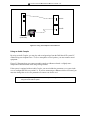
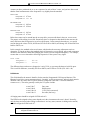
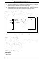
2.2.4 Making Local Connections to the Board
When you create mailboxes, Routing boxes, or other boxes on the system, you have the option to record
names and greetings at the time you create the box. You make these recordings by selecting from
recording options available directly from box setup screens. On DOS-based VP systems, to make
recordings from the VP system PC, you must attach a telephone directly to the voice board in the VP
system using one of the two techniques detailed below.
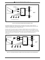
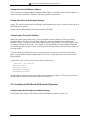
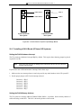
Using Two Telephone Lines
To make a local connection to the voice board in the VP system, connect one line (call it line A) to the
upper RJ-14 jack on the voice board. Connect the other line (line B) to a regular telephone, as illustrated
in Figure 2-4.
2-5
INSTALLATION AND MAINTENANCE MANUAL 9.0 VER. 1.A
Line A
Line B
Voice board
(rear view)
Figure 2-4 Using Two Telephone Lines to Record
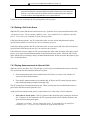
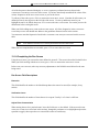
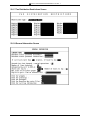
Using an Audio Coupler
By using an Audio Coupler, you can play and record greetings from the DOS-based VP system PC
without using two telephone lines. To use a microphone or local speaker, you must connect sound
equipment.
Figure 2-5 illustrates how you connect an audio coupler to a Rhetorex board—a slightly more
complicated connection than when using Dialogic boards.
If the system is equipped with an Audio Coupler, you must include the parameter LOCAL SPKR in the
VM.CFG configuration file (see section 12). If you are connecting to a Rhetorex 408 or 432 board, you
must also change the VM.CFG file parameter DATABASE LINE from 1 to 4.
Note:
When making recordings on DOS-based VP systems using an Audio Coupler, record
using the MICROPHONE option.
2-6
INSTALLATION AND MAINTENANCE MANUAL 9.0 VER. 1.A
Microphone
Connect at D for 408,
432 boards
(Database line=4)
D
C
Mixer
B
A
In
RHETOREX board
Out
Connect at A for
2132, 4132 boards
(Database line=1)
Amplifier / speaker
Audio
Coupler
Figure 2-5 Recording via an Audio Coupler on a System with Rhetorex Boards
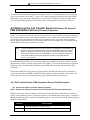
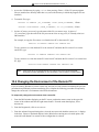
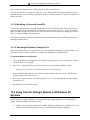
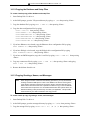
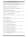
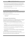
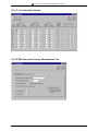
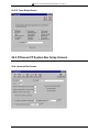
2.3 Moving Greetings, Prompts, Messages, and Mailboxes
from DOS-based to NT-based VP Systems
The NT-based VP system includes a conversion utility that allows you to easily move greetings, prompts,
messages, and mailboxes from DOS-based VP systems to NT-based VP systems. To use the utility to
convert and copy files between two separate PCs, you must back up the directories indicated in step 3
below (and their files) from the DOS-based PC onto a tape backup or Zip drive then restore them from
that media onto the NT machine.
The conversion utility is named DCONVERT.EXE, and it is located (by default) in the \VM directory.
To transfer files from the DOS-based VP system to NT-based VP system:
1. From the Start button at the bottom of the Windows NT desktop, select Run.
2. In the Open field of the Run dialog box, type C:\VM\DCONVERT.EXE then select the OK button.
3. On the screen that displays, indicate in the appropriate fields the complete paths to the database
(.DVM) files, message files, greeting files, and prompt files as they are stored on the DOS-based VP
system PC (or on the NT-based PC if you moved the files from the DOS-based PC to the NT-based
PC for conversion as discussed above). Refer to section 16 for information on the default VP system
file organization structure. Also indicate in the appropriate fields the complete paths to the database
files, message files, greeting files, and prompt files as they are to be stored on the NT-based VP
system. The default directory structure is indicated in the paths shown in each area. You must
modify the drive designation letters as necessary to accommodate the file transfer technique you are
using (from drive to drive or from PC to tape, for example).
2-7
INSTALLATION AND MAINTENANCE MANUAL 9.0 VER. 1.A
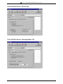
4. Indicate in the appropriate fields the type of conversion you need to perform: In the top half of the
screen, select the Dialogic or Rhetorex option to identify whether the DOS-based VP system used
Dialogic or Rhetorex boards. In the bottom half of the screen, it is recommended you retain the .WAV
file format set as the default.
5. To initiate the conversion, select the Convert Now button. Files are copied and converted as
necessary to the destinations you indicated.
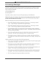
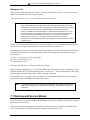
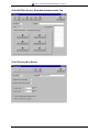
2.4 Starting the VP System, Logging in, and Shutting It Down
By default, all VP systems are configured to start running the voice processing system automatically upon
boot-up. Should you exit the system to perform maintenance or make configuration file changes, simply
restart the VP system PC. The VP system loads after the restart.
To manually start the VP system:
•
On DOS-based VP systems, change to the \VM directory and type VMAIL (if the system uses
Dialogic voice boards) or RMAIL (if the system uses Rhetorex voice boards), then press <Enter>.
•
On NT-based VP systems, start the KVT Voice Mail Manager service: Select the Start button at
the bottom of the Windows NT desktop, then choose Settings / Control Panel / Services. From
the SERVICES screen that displays, highlight KVT VOICE MAIL MANAGER then select the Startup
button. On the screen that displays, select the AUTOMATIC option then click on the OK button.
Before you can access the VP system database, you must log in by entering a password. On DOS-based
VP systems, you access the password entry field by pressing <F10> from the LINE STATUS screen (the
screen displayed when the VP system starts). On NT-based VP systems, you access the password entry
field by clicking on the DATABASE ADMINISTRATOR icon on the Windows NT desktop.
There are two levels of password security, the Customer level (referred to as the Administrator level on
NT-based systems) and the Technician level. If you enter the Customer / Administrator password, you
are provided access to everything on the VP system except the technical setup fields on several system
setup screens. Though you are able to view the technical information, you cannot modify it. If you enter
the Technician password, you are provided access to everything on the VP system. The default Customer
/ Administrator password is blank, and the default Technician password is 1234.
To shut down a DOS-based VP system, press <Esc>. At the prompt to enter a password, enter either the
Customer or Technician password. The system stops processing new calls and waits while calls in
progress are completed. Once all ports are clear, the system shuts down the VP system software program.
If absolutely necessary, you can force a DOS-based VP system to shut down immediately by pressing
<F10> when prompted. Use caution when forcing the system to immediately shut-down, as all calls in
progress are immediately disconnected.
To shut down an NT-based VP system, you must stop the VP system engine’s service. Be advised that
when you stop the engine’s service, all calls currently being handled by the VP system are immediately
terminated.
To stop the VP system engine’s service, from the Windows NT desktop, click on the Start button, then
choose Settings / Control Panel / Services. From the SERVICES screen that displays, highlight KVT VOICE
MAIL MANAGER then click on the Stop button.
2-8
INSTALLATION AND MAINTENANCE MANUAL 9.0 VER. 1.A
To exit the SERVICES screen, click on the Close button.
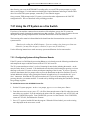
2.5 Collecting Necessary Information
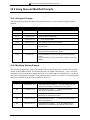
2.5.1 Application and User Setup Information
While setting up the VP system, you may need to adjust default settings for the customer’s regular
business open hours and business closed hours. You also need to set up Routing boxes to handle
incoming calls and set up mailboxes for subscribers who will be using the system. The following
worksheets are provided to help the installing technician collect this information from the system
supervisor.
Hint:
Additional worksheets for these and other system setup functions are provided in the
Implementation Handbook.
2-9
INSTALLATION AND MAINTENANCE MANUAL 9.0 VER. 1.A
2-10
INSTALLATION AND MAINTENANCE MANUAL 9.0 VER. 1.A
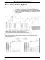
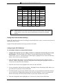
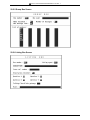
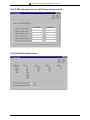
Business Hours/Holiday Worksheet (System Supervisor Completes)
On the lines corresponding to each day of the week, write in 24-hour format
(for example 8:00 PM is 20:00) the normal hours the company opens and
closes for business. If the business is open 24 hours on a particular day,
enter 0:00 as the DAY SERVICE BEGINS time and 24:00 as the DAY SERVICE
ENDS time. If the business is closed the entire day on a particular day, enter
0:00 on both lines.
Indicate, if appropriate, any
hour(s) during which the
business closes during the
day, for lunch or any other
reason.
Specify the time of day the
automated attendant should
start answering calls with a
“good evening” greeting.
Below, indicate each holiday on which the business is closed by writing the month and day. Do not
complete the INITIAL BOX field.
2-11
INSTALLATION AND MAINTENANCE MANUAL 9.0 VER. 1.A
2-12
INSTALLATION AND MAINTENANCE MANUAL 9.0 VER. 1.A
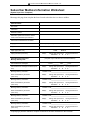
Subscriber Mailbox Information Worksheet
(System Supervisor Completes) x
Photocopy this page, then complete the form for each subscriber who is to have a mailbox.
Subscriber Data
First name:
Last name:
Extension number:
Should the system announce the caller’s
name to the subscriber upon transfer?
Should all conversations be recorded?
Paging Data
(complete only if subscriber is to use the feature)
Pager number
Pager type (circle one)
Paging schedule (circle one)
Auto Message Forward and
Message Delivery Data
TONE
Always
Message delivery schedule 1:
When should delivery be active?
(circle one):
Message delivery schedule 2:
When should delivery be active?
(circle one):
Message delivery schedule 3:
When should delivery be active?
(circle one):
Message delivery schedule 4:
When should delivery be active?
(circle one):
Message delivery schedule 5:
When should delivery be active?
(circle one):
During office open hours
Schedule*: A
B
During closed hours
C D
(complete only if subscriber is to use these features)
Auto forward new messages:
Auto forward new messages schedule (circle
one):
DIGITAL
To box:________
Always
After ______hours
During office open hours
Schedule*: A
B
During closed hours
C D
Number to call:___________________________________
Always
During office open hours
Schedule*: A
B
During closed hours
C D
Number to call:___________________________________
Always
During office open hours
Schedule*: A
B
During closed hours
C D
Number to call:___________________________________
Always
During office open hours
Schedule*: A
B
During closed hours
C D
Number to call:___________________________________
Always
During office open hours
Schedule*: A
B
During closed hours
C D
Number to call:___________________________________
Always
During office open hours
Schedule*: A
B
During closed hours
C D
*If specifying a particular schedule, complete a subscriber schedule worksheet for the individual.
2-13
INSTALLATION AND MAINTENANCE MANUAL 9.0 VER. 1.A
2-14
INSTALLATION AND MAINTENANCE MANUAL 9.0 VER. 1.A
Subscriber Schedule Worksheet
(System Supervisor Completes)
Photocopy this page, then complete the form for each subscriber who is using the Paging, Auto Message
Forwarding, or Message Delivery out-calling features according to a particular schedule, as indicated on
his/her Subscriber Mailbox Information sheet.
You can designate up to 4 different schedules below, then apply one schedule to each out-calling feature
the subscriber will be using. Enter information for 1 to 4 schedules below in 24-hour format (for example
8:00 PM is 20:00). You do not need to complete the BOX NUMBER field.
2-15
INSTALLATION AND MAINTENANCE MANUAL 9.0 VER. 1.A
2-16
INSTALLATION AND MAINTENANCE MANUAL 9.0 VER. 1.A
Routing Worksheet (System Supervisor Completes)
See section 5.7 to familiarize yourself with the function of Routing boxes. This section also provides a
sample of greetings that are typically recorded in the 3 Routing boxes pre-configured on VP systems.
After reviewing this information, complete this worksheet to indicate the wording for the greetings you
want this VP system to voice.
Note that you should indicate in your greeting any single-digit call routing options you want to provide to
callers (“…Press 2 for Sales…”) and identify the extension to which a caller pressing that single-digit
number should be transferred.
Office Open Greeting:
Single digit routing paths:
Office Closed Greeting:
Single digit routing paths:
Office Holiday Greeting:
Single digit routing paths:
2-17
INSTALLATION AND MAINTENANCE MANUAL 9.0 VER. 1.A
2-18
INSTALLATION AND MAINTENANCE MANUAL 9.0 VER. 1.A
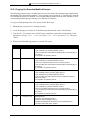
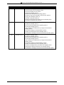
2.5.2 Phone System Information
When a company hires a new attendant, they must train the individual on how to work with the telephone
system (for example, how to transfer calls, how to get a line on hold back if the called party is busy, etc.).
The same information must be supplied to the VP system.
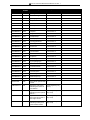
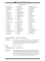
When you run the Setup utility (see section 3), you are prompted to indicate which telephone system you
are using with this VP system. You specify the telephone system by choosing it from a list of systems,
which is shown below. If the customer’s telephone system is on this list when you select it during Setup,
the VP system pre-loads specific configuration information to set up (or “train”) the VP system to work
with the specific telephone system.
Note: Not all integrations listed below are available on all VP systems.
•
•
•
•
•
•
•
•
•
•
•
•
•
•
•
•
•
•
•
•
•
•
•
•
•
•
•
•
•
•
Comdial DigiTech / Impact / DSU - Serial
Integration
Comdial DigiTech / Impact / DSU - Serial
Integration - IVPC
Comdial DXP, DXP Plus, FX - Serial
Integration
Comdial DXP, DXP Plus, FX - Serial
Integration - IVPC
Comdial Executech 2000
Comdial Unisyn
Cortelco Aries
Encore CX - ECX 1832 / 3672 / 36112
Ericsson MD-110
Fujitsu 9600 with Serial Integration
Fujitsu Allegra 26
Fujitsu Series 3 / Starlog
Fujitsu Starlog
Harris 20/20
Isoetec IDS 108 / 228
Isoetec System 96
ITT / Cortelco System 3100
Iwatsu ADIX
Iwatsu ZT-D
Lucent Definity G3 – Calista Box – Vectoring
– Bridged Mode
Lucent Definity G3 – VoiceBridge
Lucent Definity G3 – VoiceBridge – Vectoring
– Bridged Mode
Lucent Merlin II
Lucent Merlin Legend
Lucent Partner ACS
Lucent Partner II
Lucent Partner Plus
Lucent System 25
Lucent System 75
Lucent System 85 and Definity Generic 2 –
VoiceBridge
•
•
•
•
•
•
•
•
•
•
•
•
•
•
•
•
•
•
•
•
•
•
•
•
•
•
•
•
•
•
•
•
2-19
Mitel COV with D/42D-SX Voice Boards
Mitel SX100 Digital PABX with ONS
Integration
Mitel SX200 Light with COV Integration
Mitel SX200 Light with DNIC Integration
Mitel SX200 Light with ONS Integration
Mitel SX2000 and SX2000 Light with COV
Integration
Mitel SX2000 and SX2000 Light with DNIC
Integration
Mitel SX50 with COV Integration
Mitel SX50 with DNIC Integration
NEC Electra Professional Level I
NEC Electra Professional Level II
NEC Mark II
NEC NEAX-1400 IMS
NEC NEAX-2000
NEC NEAX-2400 Serial Integration
Nitsuko DSO-1 / ONYX / 124i / 384i
Northeren Telecom Norstar D42NS
Northern Telecom Norstar - With VMI
Adapters
Northern Telecom SL-1 and Meridian-1/SL-1,
(with D42-SL)
Panasonic 1232 - Analog
Panasonic DBS
Panasonic KXT-336
Panasonic KX-TD 1232 Digital
Panther II 820 / 1032 / 2064 Release IV
Philips SOPHO-S
Premier ESP / Intertel GMX
Redwood 3.2
Rolm 9200 BCS / Siemens HCM 200
Samsung Prostar 56EX / 120MX / 1224
Samsung Prostar DCS - Digital
Siemens Saturn I, II, III
SMDI Installation Guide / Centrex
INSTALLATION AND MAINTENANCE MANUAL 9.0 VER. 1.A
•
•
•
•
•
•
•
•
•
•
•
•
•
•
•
•
Southwestern Bell Landmark DKS 308 / 616
Sprint Protégé / Macrotel MT360 / 824 KSU
Tadiran Coral I, II, & III
Telrad 2464
Telrad Digital Key BX, 200 Digital
Toshiba DK-16 / 24 / 56 / 96
Toshiba DK-280
Toshiba Perception E
Toshiba Perception EX
Toshiba Perception I & II
Vodavi DHS
Vodavi Infinite DVX1, DVX2, & DVX3
Vodavi Starplus 2448EX / 4896EX
Vodavi Starplus 96EX
Vodavi Starplus Digital
Win 100D
If the customer’s telephone system is not on the list, you may need to manually input the configuration
information that sets up the VP system to work with the specific phone system. You can gather all
configuration information you will need to enter by working with the telephone system to answer the
following questions:
•
If you are on a call on a single-line telephone, and you want to transfer the call to someone else,
what action do you take?
•
Once you have initiated the transfer and spoken to the called party, what action do you take to
connect the two parties, then drop out of the call?
•
If you initiated the transfer, but the new party is busy, how do you reconnect to the original
caller?
•
If you initiated the transfer, but the new party does not answer, how do you reconnect to the
original caller?
•
If the system includes message waiting lamps, how do you turn them on and off?
•
What is the required duration of a hook-flash?
•
Does the telephone system provide any form of in-band (DTMF) or out-of-band (serial link)
voice mail integration?
•
What is the maximum length of an extension number (usually 3 or 4 digits)?
To verify that the information you have collected is correct, try each of the actions discussed above from
the line or lines that the VP system will be using. This can be done by connecting an industry-standard
telephone to the extension port, and using this telephone to perform all the functions the VP system is to
do. As you perform each function (for example, answering an incoming call and transferring it to another
extension), make a note of the steps that were required. For example, to transfer a call on a PBX to an
extension, you may need to hook-flash, wait for dial-tone, and then dial the extension number. When the
extension answers, you may then have to go on-hook to complete the transfer. If the called party is busy,
you may have to hook-flash again to get back to the original incoming call.
2-20
INSTALLATION AND MAINTENANCE MANUAL 9.0 VER. 1.A
2.6 Understanding the System Setup Steps
Once you connect VP system to the phone system and collect all necessary setup information, you are
ready to begin customizing the system. Customizing the system involves:
•
•
•
Running the PBX Setup utility (also referred to as the First Time Setup utility)
Specifying system information on System Information screens and in the VM.CFG file
Specifying Routing box, mailbox, and other box setup information on box screens
The following sections in this manual detail the procedures for completing each of these tasks.
2-21
INSTALLATION AND MAINTENANCE MANUAL 9.0 VER. 1.A
2-22
INSTALLATION AND MAINTENANCE MANUAL 9.0 VER. 1
3. Running the PBX Setup Utility
Even if the VP system software is pre-installed on the system before it is shipped to you, you must run
the PBX Setup utility (also referred to as the First Time Setup utility) so you can configure certain
installation parameters for each specific customer’s site. Use the following procedures to run the PBX
Setup utility using the VP system screen interface.
(If you installed a kit VP system using procedures in section 21, you ran the PBX Setup utility during the
kit system installation. Therefore, you can skip this section.)
The procedure you use to run the Setup utility depends on whether you are working with a DOS-based
VP system or an NT-based VP system.
Note:
For procedures on running the PBX Setup utility through the teleparameter feature, see
section 11.
To run the PBX Setup utility through the DOS-based VP system screen interface:
1. If the VP system has pre-loaded and is running on-screen, exit to a DOS prompt by pressing <Ctrl><Esc> then <Enter>.
2. To switch to the VM directory, type CD\VM then press <Enter>.
3. To invoke the Install program, type INSTALL then press <Enter>.
4. When the main Install menu displays, use the ↓ key to highlight FIRST TIME SETUP then press
<Enter>.
5. When prompted, type C:\VM then press <Enter> to indicate the directory in which the VP system
is installed.
6. The system warns that it may overwrite some changes to the database. To continue, press <Y>.
7. At the system prompt for the number of digits in the extension numbers, enter the appropriate
number then press <Enter>. At the system prompt to confirm your entry, press <Enter>.
8. A list of telephone systems displays. Note that you can use the <PgUp> and <PgDn> keys to scroll
through all available selections. Enter the number corresponding to the telephone system with which
you are working, then press <Enter>. If the phone system is not on the list, select option
0 DON’T KNOW (OR UNLISTED) then press <Enter>.
9. The system prompts you to confirm your selection. To continue, press <Y>.
10. At the system prompt regarding message waiting lights, press <Y>.
11. The system prompts you to indicate the number of telephone lines connected to the VP system. Enter
the appropriate number, then press <Enter>.
12. The system prompts you for the number of digits you want to use in mailbox passwords. Indicate the
number of digits subscribers are to use, then press <Enter>. (You may want to consult the system
supervisor, in case he/she has a digit-length preference.)
3-1
INSTALLATION AND MAINTENANCE MANUAL 9.0 VER. 1
13. The system prompts you to confirm your selection. To continue, press <Y>.
14. The system prompts you to automatically create mailboxes at this point. Though you may elect to
create mailboxes now, we strongly recommend that you select No, so you can first make any
necessary modifications to the prototype mailbox, which serves as a template for creating mailboxes.
By properly setting up the prototype mailbox, you simplify the number of adjustments you must
make to refine the mailboxes for each user. To continue without setting up mailboxes at this time,
press <N>.
15. Depending on the phone system you selected, you may be prompted for additional information.
Enter the appropriate responses.
16. The system prompts you to use U.S. Daylight-Savings Time. To have the system automatically
adjust the clock so it accommodates Daylight-Savings Time for the next 10 years, press <Y>. If you
do not want the system to automatically adjust for U.S. Daylight-Savings Time, press <N>.
17. The main Install program screen displays. To continue, select Exit then press <Enter>.
18. The Install program must re-boot the VP system to make the changes indicated. Press <Y> when the
system displays the re-boot prompt. After the system reboots, the Line Status screen displays.
To run the PBX Setup utility through the NT-based VP system screen interface:
1. Shut down the VP system if it is running.
2. From the Windows NT desktop, double-click on the PBX SETUP icon. This icon displays on the
desktop only until it is selected once. It is then deleted from the desktop. To run the PBX Setup
utility after the first time, access the utility by clicking on the Start button, selecting the Run option,
and typing C:\VM\PBXSETUP.EXE then clicking the OK button in the OPEN field of the Run
dialog box.
3. From the WELCOME screen that displays, click on the Next button.
4. At the prompt, highlight the phone system with which this VP system is being installed. Use the
scroll bar to view all available options. Once you highlight a system, click on the Next button to
continue.
5. At the prompt, indicate the maximum number of digits to be used in phone system extensions. To
continue, click on the Next button.
6. At the prompt, indicate the maximum number of digits subscribers are to use in mailbox passwords.
To continue, click on the Next button.
7. If you did not select a Comdial phone system, continue with step 8. If you selected a Comdial phone
system, at the prompt, indicate whether you want to use LCD and Record Call features as discussed
on the screen. Also indicate whether all mailboxes will use a serial link to control message waiting
lamps and whether the site is using PCIU devices with the Visual Call Management (VCM) optional
module by checking or un-checking the boxes provided. To continue, click on the Next button.
If you selected a Comdial phone system, indicate the extension number associated with each voice
mail port on the system. Once you specify an extension number for every port, click on the OK
button to continue.
3-2
INSTALLATION AND MAINTENANCE MANUAL 9.0 VER. 1
8. On the CONFIRM SETUP INFORMATION screen, review the selections you made. To change a
selection, click on the Change button and follow the prompts. Once all selections are acceptable,
click on the Finish button.
9. On the PBX SETUP COMPLETE screen, click on the OK button to continue.
10. You must re-start the VP system PC to invoke the changes you made. Select the RESTART NOW
option, then select the Finish button. The PC restarts and the VP system loads.
3-3
INSTALLATION AND MAINTENANCE MANUAL 9.0 VER. 1
3-4
INSTALLATION AND MAINTENANCE MANUAL 9.0 VER. 1.A
4. Setting up System Information
System Information screens contain setup information that applies system-wide, to all boxes set up on the
system. VP systems include the following System Information screens:
•
•
•
•
•
•
•
•
•
GENERAL INFORMATION screen
LINE INFORMATION screen
BUSINESS HOURS screen
HOLIDAY SCHEDULE screen
CALL TRANSFER screen / PBX INFORMATION screen
TECHNICAL INFORMATION screen (DOS-based VP systems only)
CLASS OF SERVICE screens
OTHER CUSTOMIZATIONS screen (DOS-based VP systems only)
Diagnostic menu screens (NT-based VP systems only)
Two important sets of fields found on the OTHER CUSTOMIZATIONS screen in DOS-based VP systems are
housed on a separate pull-down menu in NT-based VP systems. These fields are the TRACE and
CUSTOM/DEBUG fields. In NT-based VP systems, these fields are found on the Diagnostics pull-down
menu under the options TRACE SETUP and CUSTOM FLAGS. Information on these options is provided at
the end of this section.
Before you set up Routing boxes, mailboxes, or any other boxes on the system, it is best to ensure all
System Information screens are properly completed.
Note:
You can access online help on any screen at any time by pressing <F1>.
4.1 Integration Defaults Set by the Setup Utility
When you run the Setup utility (see section 3), you are prompted to indicate the type of telephone system
the customer is using. If you are installing the VP system on one of the phone systems listed, the Setup
utility automatically sets fields on several System Information screens to the phone system’s default
settings. Unless you customize the phone system defaults, you probably do not need to modify these
settings.
If you are using a telephone system that is not listed in the Setup utility, the utility sets fields on System
Information screens to commonly used defaults. You may need to adjust these settings.
4.2 Using Technical Bulletin Information
For almost every telephone system supported by the VP system, there is a technical bulletin that details
telephone-specific installation considerations and telephone-specific default values that are pre-set on
System Information screens when you run the Setup utility. This information is particularly useful if you
are working with a phone system that is not specifically listed when you run the Setup utility—primarily
because it is more likely you will need to adjust settings on System Information screens.
4-1
INSTALLATION AND MAINTENANCE MANUAL 9.0 VER. 1.A
You can obtain technical bulletins through the Key Voice web site at KEYVOICE.COM or through the Key
Voice fax distribution system. To access this system, phone (941) 922-3800 and press 7 at the main
greeting. Follow the system prompts and, when requested, enter the number corresponding to the bulletin
for the phone system with which you are working. To obtain a listing of all available bulletins and their
associated bulletin numbers, request document 01.
4.3 Accessing System Information Screens
Note:
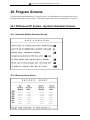
Refer to section 29 for graphical illustrations of all VP system screens.
To access System Information screens through the DOS-based VP system screen interface:
1. From the LINE STATUS screen, press <F10>. The Main menu displays, and you are prompted to enter
a password.
2. Type 1234 then press <Enter> to log on using the default Technician level password. You can
change both the Technician and Customer level passwords on the GENERAL INFORMATION screen.
3. From the Main menu, select SYSTEM INFORMATION. The System Information menu displays.
4. Select the screen you want to review or modify from the System Information menu. When you have
made any necessary modifications to the screen, press <F10> to save the changes. You return to the
System Information menu.
To access System Information screens through the NT-based VP system screen interface:
1. From the Windows NT desktop, double-click the DATABASE ADMINISTRATOR icon. You are
prompted to enter a password.
2. Type 1234 then press <Enter> to log on using the default Technician level password. You can
change both the Technician and Administrator level passwords on the GENERAL INFORMATION
screen.
3. Access the System pull-down menu.
4. Select the screen you want to review or modify from the System menu. When you have made any
necessary modifications to the screen, press <F10> to save the changes or click on the Save icon on
the screen. You return to the main screen.
Note:
Field names and screen descriptions for both DOS-based and NT-based VP systems
screens are presented in this section. Each field description identifies the field name used
in both types of products. Be advised that due to differences in the screen design
between DOS-based and NT-based VP systems, the placement of fields on several
screens vary slightly. All fields on all screens are discussed in this section.
Note:
To locate the information on a particular field most easily, consult the Index to find
the page number of this document that contains the field description.
4-2
INSTALLATION AND MAINTENANCE MANUAL 9.0 VER. 1.A
4.4 Setting Up the General Information Screen
Be advised that due to differences in the screen design between DOS-based and NT-based VP systems,
the placement of fields on several system screens vary slightly. To locate the information on a particular
field most easily, consult the Index to find the page number of this document that contains the field
description.
Fields used in DOS-based VP systems are prefaced below with VP, and fields used in NT-based VP
systems are prefaced with NTVP. If the NTVP field resides on a certain tab on the screen or if the VP
field resides on a certain screen page, the tab or page is identified next to the field name.
Several field descriptions discuss setting fields to YES or NO settings. In NT-based VP systems, this
equates to checking or un-checking the field’s checkbox, which you do by clicking on it.
4.4.1 General Information Screen Field Descriptions
VP: Company Name
NTVP: Company Name
This field identifies the name of the company using the VP system. The company name appears on
database listings and outgoing fax documents.
VP: Database Access Password (Customer)
Database Access Password (Technician)
NTVP: Administrator Password (Security tab)
Technician Password (Security tab)
To prevent unauthorized personnel from accessing the VP system database, choose database passwords,
and enter them here. Each password can consist of up to 10 letters or digits.
There are two levels of password security, the Customer level (referred to as the Administrator level on
NT-based systems) and the Technician level. If you enter the Customer / Administrator password, you
are provided access to everything on the VP system except the technical setup fields on several system
setup screens. Though you are able to view the technical information, you cannot modify it. If you enter
the Technician password, you are provided access to everything on the VP system. The default Customer
/ Administrator password is blank, and the default Technician password is 1234
When you access the GENERAL INFORMATION screen, the passwords are not displayed. Instead, the fields
are filled with stars. You can still access the fields and change the passwords, but you cannot see the
current password. If you accessed the VP system using the Technician password, you can access and
change both password fields. If you accessed the VP system using the Customer / Administrator
password, you can access and change only that password field.
VP: (See Other Customizations screen for comparable field)
NTVP: Display Mailbox Passwords on Screen (Miscellaneous tab)
When the VP system displays the MAILBOX screen on the PC screen, there is a field PASSWORD that
contains the mailbox owner’s password. If you do not want the password to display on the screen, choose
4-3
INSTALLATION AND MAINTENANCE MANUAL 9.0 VER. 1.A
NO here.
The PASSWORD field will be filled with stars. You can still access the PASSWORD field, and
change the password if required, but you cannot view the current password.
VP: If Call Lasts More Than x Minutes, Go to Box
NTVP: If Call Lasts More Than x Minutes, Go to Box (Miscellaneous tab)
This field allows you to limit the amount of time that a call remains in the VP system. For standard voice
mail / automated attendant operation, caller activity is usually limited to transferring to an extension or
leaving message in a mailbox (you can limit the amount of time for a message in the class of service
assigned to the mailbox). There may be some cases, however, when you want to prevent callers from
spending an unlimited amount of time on a single call. Some examples are:
•
Call queuing—If you are allowing the VP system to queue calls to busy stations, you may want to
limit the maximum amount of time that a caller can hold. In normal operation, the system returns
to the calling party after a pre-determined number of tries to a busy extension and asks if he/she
wants to remain on hold. If you do not set a time limit here, the caller can request to remain on
hold for an unlimited amount of time.
•
Talking classifieds—If the system includes the optional Talking Classifieds module, you may
want to limit the time a caller may “browse” through the listings.
When you enter a time in the MINUTES field, the VP system keeps track of each incoming call. When the
maximum time limit has been reached, the VP system completes the current operation (such as playing a
prompt or greeting, recording a message, etc.), routes the caller to the box specified in the re-route to box
field. This is typically a Routing box with a greeting such as:
“I’m sorry, you have exceeded the maximum allowed time for this call. Please call again at a later time.”
You can set up this box to disconnect the call after playing the greeting, or you can have it transfer the
call to a live operator.
Note:
When the MINUTES field is set to zero (0), this feature is disabled and there is no time
limit in effect. Callers may stay connected to the VP system as long they stay on the line.
VP: (See Technical Information screen for comparable field)
NTVP: Automatically Update All MWI Lamps at (Miscellaneous tab)
Some telephone system automatically cancel all message waiting lamps at a pre-set time (such as
Midnight). Also, many telephone systems do not restore the state of message waiting lamps following a
power failure. You may program the VP system to automatically re-send the message waiting lamp ON
sequence for every mailbox with new messages, and the OFF sequence for every mailbox with no new
messages, once each day at this time. The following limitations must be considered:
•
•
The VP system may need to make dozens or even hundreds of calls to update all message waiting
lamps on the system. The time you enter here should be at the time of lowest activity on the
system.
On DOS-based VP systems, the time set here should not conflict with the daily EXIT TO DOS
TIME (see below).
Some telephone systems do not allow unnecessary added MESSAGE WAITING ON indications to be set.
4-4
INSTALLATION AND MAINTENANCE MANUAL 9.0 VER. 1.A
If you are not experiencing problems with message waiting lamps, leave this field blank. Intermittent
performance of message waiting lamps may be caused by problems that are not related to the use of this
feature.
Note:
If you have only an occasional problem with message waiting lamps (such as a power
failure), you can invoke the message waiting update manually. From the main screen,
press <Ctrl-F1> simultaneously. The update process begins, and you see an advisory
message on the screen that the update is running. To cancel the update before it
completes, press <Ctrl-F2>.
VP: Number of Boxes to Log
NTVP: Number of Boxes to Track in Log (Miscellaneous tab)
In the call logging record for each call, the VP system stores an audit trail of all the boxes the caller
accessed during the call. The default is for the VP system to store only the first 9 boxes, but you can set
this number to any value between 1 and 99. The VP system includes this number of boxes in every call
record in the log file. If the call used fewer boxes than the number you specify here, the VP system
includes a blank box number in the log file for each missing box. If the log information is being sent to a
file, each box number is enclosed in quotation marks, including the blank boxes.
VP: (See Call Transfer screen for comparable field)
NTVP: Digits that Mean YES in Response to a Yes/No Question (Miscellaneous tab)
There are several occasions when the VP system asks the caller for confirmation. For example, when the
caller enters his/her pager callback number, the VP system repeats it and says, “If this is correct, press 1.”
All digits you list in this field are considered “Yes” answers. Any other key is treated as “No.” Be
advised that entries in this field affect all boxes set up on the system, not just a particular box.
If you choose to use another number instead of 1 to mean “Yes,” you must re-record the prompts that
specify the number ‘1’ and change them to ask for the new number (see section 15). This includes
prompts voiced in the following situations:
•
Sending a message from within an open mailbox. The VP system says the recipient’s name, and
then voices the prompt, “If this is correct, press 1.”
•
During a message notification call. The VP system waits for the called party to answer, then
says, “Message for [name]. Press 1 if you would like to hear your messages.”
•
During a three-way call. To ensure the call is still active, the VP system periodically comes on
the line and says, “Excuse me, please press 1 if you wish to continue your call.”
VP: (See Other Customizations screen for comparable field)
NTVP: Display Mail-Box Passwords on Screen (Miscellaneous tab)
When the VP system displays the MAILBOX screen on the PC screen, there is a field PASSWORD that
contains the mailbox owner’s password. If you do not want the password to display on the screen, choose
NO here. The PASSWORD field will be filled with stars. You can still access the PASSWORD field, and
change the password if required, but you cannot view the current password.
4-5
INSTALLATION AND MAINTENANCE MANUAL 9.0 VER. 1.A
VP: Number of Lines Detected
NTVP: (No such field)
This field cannot be change from the keyboard. The VP system examines the hardware in the computer,
counts the number of voice processing boards installed, and counts the number of lines each board can
accommodate. It then displays the maximum number of lines here.
VP: Automatically Exit to DOS at
NTVP: (No such field)
DOS-based VP systems need to perform various maintenance tasks on a regular basis, such as defragmenting the PC’s hard disk. To perform these tasks, it needs to exit to DOS. Use this field to specify
a time that the VP system can automatically exit to DOS each day. It is important to choose a time of the
day when the system is least busy (for example, 2:00 AM) and enter that time in this field to make the
feature active (if you enter 00:00 in this field, this feature is disabled). The automatic exit to DOS feature
is important for two reasons:
•
When the VP system exits to DOS and re-loads, an AUDIT DATABASE program runs and checks
the integrity of the voice prompts and system boxes.
•
Every Wednesday, a batch file is programmed to run a hard disk drive defragmenting program.
This keeps the VP system running at its peak operating performance. The batch program may
take up to 30 minutes or more to run.
When the program exits to DOS to perform maintenance functions, you can schedule it to perform other
tasks, such as backups. Program these other tasks to be called from the DISKM.BAT file.
VP: Store Call Log to
NTVP: Call logging area
When you move the cursor to this field, a menu displays, offering options for the call logging feature.
You can turn call logging off or send the output to a printer or to a file.
If you select to send logs to the printer, verify:
•
The printer is attached to LPT1 on the PC.
•
The printer is turned on and is on-line.
•
The printer is set to perform a CARRIAGE-RETURN and LINE-FEED when it receives a line feed
character (such as an automatic carriage-return). Consult the printer documentation for
information on adjusting these settings.
If you choose to store call logs to a file, the VP system creates a file called VOICMAIL.LOG in the \VM\LOG
directory. All log information is written to that file. At midnight each night, the contents of
VOICMAIL.LOG are transferred to another file in the directory \VM\LOG for long-term storage. The name
of the long-term storage file is based on the month and day. On February 15, for example, the daily log
file is stored as VOICEMAIL.LOG. At midnight, the contents of VOICEMAIL.LOG are copied to the file
0215.LOG, and the file VOICEMAIL.LOG is cleared to record the log of calls on February 16. At midnight
on February 16, the contents of VOICEMAIL.LOG are copied to the file 0216.LOG, and VOICEMAIL.LOG is
cleared to record the log of calls on February 17.
4-6
INSTALLATION AND MAINTENANCE MANUAL 9.0 VER. 1.A
Up to one year’s worth of information can be stored. After that, the VP system begins over-writing the
previous year’s log files.
VP: Max Calls on On-Screen Graph
NTVP: (No such field)
One of the on-line displays is a set of graphs showing the number of incoming calls received per hour for
the current and previous day. You can specify the maximum value for the vertical scale on the graph. If
you set this value to 0, the VP system automatically chooses the best scale, according to the number of
calls received.
VP: (See Technical Information screen for comparable field)
NTVP: Stop Recording After X Seconds of Silence (Message Options tab)
When the VP system is recording a message, it determines that the caller has finished speaking if he/she
remains silent for a specific interval. Use this parameter to specify how many seconds of silence the VP
system should detect before ending recording. If you enter 0 in this field, silence detection is disabled.
Note:
If the telephone system does not provide positive disconnect (DTMF tones or a break in
loop current), you may experience silent messages in mailboxes when a caller hangs up
before leaving a message. You may use a combination of this parameter and the
parameter MINIMUM MESSAGE in the configuration file VM.CFG to minimize these
“blank” messages. Use caution when setting the NUMBER OF SECONDS OF SILENCE TO
END RECORDING parameter. If this time is set too short, you may stop recording caller’s
messages when they are simply pausing for a moment.
See section 12 for information on the MINIMUM MESSAGE parameter.
VP: (See Technical Information screen for comparable field)
NTVP: Disconnect if More than X Seconds of Continuous Sound Detected (Message Options tab)
While the VP system is recording a message, it is monitoring the line for dial tone (continuous nonsilence). If dial tone is detected, the VP system assumes the caller has hung up, and stops recording. This
field lets you specify how many seconds of continuous non-silence needs to be detected before the system
assumes it is dial tone.
Note:
If you set this number too low, a caller who pauses and says “aaaahhhh” could trigger the
dial tone detection. If you set the number too high, 15 seconds, for example, the C.O. or
PBX might remove the dial tone before it has been on the line long enough to be detected.
VP: Seconds for Fast-Forward/ Rewind Operations
NTVP: Fast-Forward/Rewind Should Jump by X Seconds (Message Options tab)
Disconnect if More than X Seconds of Continuous Sound Detected When a mailbox owner is listening to
his/her messages, he/she can use the fast-forward and rewind functions. Fast-forward forwards the
message by a pre-defined number of seconds. Rewind reverses the message that number of seconds. Use
this field to specify the number of seconds for both operations.
4-7
INSTALLATION AND MAINTENANCE MANUAL 9.0 VER. 1.A
VP: (See Other Customizations screen for comparable field)
NTVP: Play Message Time and Date (Message Options tab)
When a mailbox owner is listening to his/her messages, one of the options is to press 5 to hear the time
and date that the message was received. Use this field to control the play of the time and date of each
message. The choices are:
•
•
•
WHEN CALLER ASKS—The mailbox owner must press 5 to hear time and date (this is the default)
BEFORE EACH MESSAGE—The time and date is played automatically before each message
AFTER EACH MESSAGE—The time and date is played automatically after each message
VP: Digits to Get a Line on External Call
NTVP: (See PBX Information screen for comparable field)
If the VP system is working behind a key system or a PBX, enter the sequence of digits it should dial to
get an outside (C.O.) line when calling an external number. This number is typically a 9 followed by a
pause (9,).
Note:
The digits in this field are not involved when the VP system is making an external call
transfer. They are only used when it places an outgoing external call (for pager
notification or message delivery, for example). See section 7.3 for information on external
transfers.
VP: (See Other Customizations screen for comparable field)
NTVP: When Called Party Answers, Play His/Her Name (Transfer options tab)
This field affects only mailboxes using the WAIT FOR ANSWER or SCREEN transfer type. If this field is set
to YES, when the called party answers, the VP system announces the call. The standard format is one of
the following:
“I have a call for you, [name].”
“Call from [calling party’s name] for [name].” (if the option to get the caller’s name is active)
This prompt is useful if an extension receives calls from more that one mailbox and you want it to be
answered with the correct name of the called party. For example, several mailbox owners could change
their call transfer service to send their calls to a central answering point (see section 5.1). The person
receiving these calls can now hear who these calls are for and answer with a personalized greeting such
as, “Mr. Smith’s office,” “Mr. Jones’ office,” etc.
Setting this field to NO causes the VP system to omit the called party’s name and simply announce the
call. The format is one of the following:
“I have a call for you.”
“Call from [calling party’s name].” (if the option to get the caller’s name is active)
VP: (See Call Transfer screen for comparable field)
NTVP: Max Duration of 3-Way Call (Transfer Options tab)
Since the VP system has to stay on the line for the entire duration of a three-way call, it has to know when
both parties have finished their conversation, so it can hang up and release the line. To guard against the
4-8
INSTALLATION AND MAINTENANCE MANUAL 9.0 VER. 1.A
event that the end of the conversation is not detected, the VP system will come on the line after the
amount of time you specify here, and prompt the parties to confirm that at least one of them is still on the
call. It does this by playing the prompt, “Excuse me, press 1 if you wish to continue your call.” If either
party presses 1, the timer resets and the call can proceed. If no digit is dialed, the VP system disconnects
the call.
VP: (See Other Customizations screen for comparable field)
NTVP: When Called party Answers, Announce the Call (Transfer Options tab)
This parameter affects only the mailboxes using transfer type WAIT FOR ANSWER.
When using the WAIT FOR ANSWERtransfer type, the VP system does not connect the calling and called
parties until it confirms that the called party has answered. This is done two ways:
•
•
Voice is detected on the line
A break in the cadence of the ringback tone is detected (see section 13)
This process may take 1 to 2 seconds from the time that the called party goes offhook to answer an
incoming call. Under normal operating conditions, the VP system informs the called party that it has
detected answer by playing the system prompt:
“I have a call for you.”
Setting this parameter to NO prevents the prompt from playing. A short tone plays in its place (system
prompt 166).
Note:
Users should be made aware that when they first go off hook and answer an incoming
call, the calling party does not hear their initial answer (since the VP system does not
connect the call until it detects the answer).
VP: (See Other Customizations screen for comparable field)
NTVP: Maximum Box Length When Caller is Dialing (Transfer Options tab)
Box numbers in the VP system may be 2, 3, or 4 digits long (for example, you may have a mailbox 10, a
mailbox 100, and a Routing box 1000). To speed up call processing, you may use this parameter to
define the maximum box length that a caller might dial. Entering a number less than 4 does not mean you
cannot have any 4-digit boxes in your system, just that any 4-digit boxes can not be dialed directly by a
caller.
For example, if the telephone system uses only 3-digit extensions, you will probably have corresponding
3-digit mailboxes. In this case, enter 3 for MAXIMUM BOX LENGTH. When a caller dials a 3-digit mailbox
number, the VP system processes the call immediately, not waiting for a fourth digit.
In this example, you can still use 4-digit box numbers on the system, especially for other box types, such
as Routing boxes, provided that these boxes are accessed in a way other than the caller dialing the box
number. For example, you may use 4-digit Routing boxes as the initial boxes indicated on the LINE
INFORMATION screen, in the Routing box DESTINATION FOR DIGIT fields, in any system GO TO BOX field,
etc.
4-9
INSTALLATION AND MAINTENANCE MANUAL 9.0 VER. 1.A
Note:
If the system has Routing box numbers that are longer than the MAXIMUM BOX
LENGTH parameter, the greeting can only be recorded by using the computer keyboard.
Owners of Routing boxes are not able to remotely record or change a greeting because
when the VP system prompts the box owner to enter the box number of the greeting
he/she wants to change, the owner is not be able to dial more than the number of digits
defined in MAXIMUM BOX LENGTH.
Defining the Paths for the VP System Files
When you load the VP system files from disk, the system automatically stores the files in the directory
\VM and in several sub-directories under \VM. You may move some of the file types to other directories
(if required by your application) by setting a new path in the following fields. Note that changing the path
here does not move any of the existing files stored in the current path—you must manually move the files.
The default directory is \VM. If you choose to place files in another directory or on another drive, you
must indicate the complete path here. For information on indicating paths, consult documentation for the
operating system.
VP: Path for Prompts
NTVP: Path for Prompts (Directories tab)
When the VP system is about to play a system prompt (such as, “Please hold for…” or, “That extension
is currently unavailable…”), it looks for the speech file that contains that prompt. The system prompts
are normally stored in the sub-directory \VM\P. However, you can store them elsewhere if you use this
field to tell the VP system where to find them.
VP: Path for Greetings
NTVP: Path for Greetings (Directories tab)
When the VP system is about to play a box greeting (“For Sales, press 1, for Service, press 2,” or, “Hi,
this is Mary. Please leave me a message after the tone...”), it looks for the speech file that contains that
greeting. The box greetings are normally stored in the sub-directory \VM\M. However, you can store the
greetings elsewhere if you use this field to tell the VP system where to find them.
VP: Path for Messages
NTVP: Path for Messages (Directories tab)
When the VP system is about to play a mailbox message to the owner of the mailbox, it looks for the
speech file that contains that message. The mailbox messages are normally stored in the sub-directory
\VM\M. However, you can store them elsewhere if you use this field to tell the VP system where to find
them.
VP: Path for Question Box Voice Files
NTVP: Path for Question Box Voice Files (Directories tab)
Question box questions and answers are normally stored in the sub-directory \VM\M. However, you can
use this field to tell the VP system to store them in another directory. Changing the path here for the
questions and answers does not affect where Question box greetings are stored, which is the same path as
that used for all other system greetings.
4-10
INSTALLATION AND MAINTENANCE MANUAL 9.0 VER. 1.A
VP: Path for Call Log Information
NTVP: Path for Call Log Information (Directories tab)
If you selected FILE for the VM.CFG parameter STORE CALL LOG TO:, the VP system normally records this
information in files stored in the sub-directory VM\LOG. You may use this field to tell the VP system to
use another directory. Note that log files are automatically archived for one year, so you must have
sufficient disk space available or you must periodically delete the files. See section 7.1 for more
information on the call log.
For additional information on files, see section 16.
4.5 Setting Up the Line Information Screen
The LINE INFORMATION screen is divided into columns, and each row contains the information for one of
the VP system’s ports. If the VP system has more lines than are displayed on the screen, you can display
the additional lines by pressing <F6> or the previous 8 lines by pressing the <F5>. (NT-based VP system
users can also scroll to see all line information.)
Be advised that due to differences in the screen design between DOS-based and NT-based VP systems,
the placement of fields on several system screens vary slightly. To locate the information on a particular
field most easily, consult the Index to find the page number of this document that contains the field
description.
Fields used in DOS-based VP systems are prefaced below with VP, and fields used in NT-based VP
systems are prefaced with NTVP. If the NTVP field resides on a certain tab on the screen or if the VP
field resides on a certain screen page, the tab or page is identified next to the field name.
4.5.1 Line Information Screen Field Descriptions
VP: Initial Box (Day Service, Night Service, Lunch Service)
NTVP: Initial Box (Day Service, Night Service, Lunch Service)
When a call is first answered, the VP system checks the date and time to see if the business is open (in
Day Service mode). To make this determination, it consults the BUSINESS HOURS screen.
If the VP system is in Day Service mode, it reads the box number from this field, and routes the call to
that box. This box is typically a Routing box that plays a “welcome” greeting and offers various options
to the caller. The same process is applied when the system is in the Lunch Service mode or Night Service
mode.
VP: Rings to Answer
NTVP: Rings to Answer
The VP system answers incoming calls after the number of rings specified in this field. You can set this
parameter for Day, Night, and Lunch Service modes.
If the telephone system rings all the VP systems ports simultaneously for each incoming call, set the value
in this field to 99. This tells the VP system to answer on one port, then pause to see if the other ports stop
4-11
INSTALLATION AND MAINTENANCE MANUAL 9.0 VER. 1.A
ringing. If they do not, the VP system answers on another port (as there must have been at least two calls
ringing in), and pauses again, etc.
Note:
If you have problems with the operation of this feature, adjust the pooled ring time (see
section 12).
VP: Outgoing Calls Allowed
NTVP: Outgoing Calls Allowed
If this field is set to NO for a particular line, the VP system does not use that line when it is making
outgoing calls, to call a paging service, to perform message notification, and to set or clear messagewaiting lamps, for example.
Note:
The settings in this field are ignored for any call that is made within a specific line group
you have set up.
VP: Line Groups
NTVP: Line Groups
Use these fields to specify which lines belong to which line group. Each line group can contain zero, one,
or several lines, and each line can belong to zero, one, or several line groups. For more information on
line groups, see section 7.16
4.6 Setting Up the Business Hours Screen
Use the BUSINESS HOURS screen to define the Day Service mode period and Lunch Service mode period.
By default, any period not defined as part of Day Service or Lunch Service is considered part of Night
Service mode.
The VP system automatically switches between Day Service mode, Night Service mode, and Lunch
Service mode based on the times you enter in these fields.
Note:
A system supervisor has the ability to call into the system and override these times,
forcing the system into Day Service or Night Service at any time.
Before programming the system’s BUSINESS HOURS, see section 7.7 for a complete discussion of Day
Service, Night Service, and Lunch Service modes.
Be advised that due to differences in the screen design between DOS-based and NT-based VP systems,
the placement of fields on several system screens vary slightly. To locate the information on a particular
field most easily, consult the Index to find the page number of this document that contains the field
description.
Fields used in DOS-based VP systems are prefaced below with VP, and fields used in NT-based VP
systems are prefaced with NTVP. If the NTVP field resides on a certain tab on the screen or if the VP
field resides on a certain screen page, the tab or page is identified next to the field name.
4-12
INSTALLATION AND MAINTENANCE MANUAL 9.0 VER. 1.A
4.6.1 Business Hours Screen Field Descriptions
For each day of the week, enter the opening and closing times for the business. If the business is closed
all day, enter 00:00 in both the DAY SERVICE BEGINS and DAY SERVICE ENDS fields. This places the VP
system in the Night Service mode for that entire day.
If the business is open 24 hours on a particular day, enter 00:00 for the DAY SERVICE BEGINS time and
24:00 for the DAY SERVICE ENDS time.
Note:
All times must be entered in 24-hour format—for example, enter 8:00 PM as 20:00).
The Lunch Service mode may be used for a variety of purposes. See section 7.7.
VP: Change “Good Afternoon “ to “Good Evening” at
NTVP: Change “Good Afternoon” to “Good Evening” at
If you have recorded system prompts 171, 172, and 173, the initial greeting (as programmed in the LINE
INFORMATION screen) is automatically preceded with the appropriate prompt. Prompt 171, “Good
morning…” is voiced from midnight until noon. Prompt 172, “Good afternoon…” is voiced from Noon
until the time set here. At this time prompt 173, “Good evening…” is voiced until midnight.
If you have not recorded prompts 171, 172, and 173, you can ignore this field. These prompts are not prerecorded, since they should be recorded in the same voice as the initial greetings for best quality and
continuity.
4.7 Setting Up the Holiday Schedule Screen
Besides having the VP system answer calls differently at different times of the day, you can have the
system answer calls in a special way during various holidays. For example, on New Year’s day, the
company may be working with a smaller staff, so they may want the system to greet customers with:
“The XYZ Company wishes all its customers a Happy New Year. Our service personnel are not available
today, but will be back as usual tomorrow. For Sales, press 1, or press 0 to speak to an operator.”
You may pre-define up to 20 holiday dates. For each holiday, you can specify a different greeting or a
different call routing scheme. During the holiday, the VP system uses the greeting and call routing
scheme you have defined.
The following programming example shows how to set up a New Year’s holiday greeting to play on
January 1.
Access the HOLIDAY SCHEDULE screen and select JANUARY as the month, then enter 1 to indicate the first
day of the month. In the field INITIAL BOX, enter a spare box number (which will be set up later in this
example). In this example, box number 8500 is used.
The VP system is now advised of the New Year’s holiday. Each time a call arrives on January 1, the VP
system routes the call to box 8500, ignoring all service periods assigned on the LINE INFORMATION
screen.
4-13
INSTALLATION AND MAINTENANCE MANUAL 9.0 VER. 1.A
Note:
Holiday greetings are in effect for the entire 24-hour period of the calendar day.
To complete this example, Routing box 8500 must be created. You add Routing boxes by accessing the
ROUTING BOX screen (see section 5.7). Press <F2> to add a Routing box and type 8500 in the window
that displays. Once you create a Routing box, you can record a greeting in it (in this example, a New
Year’s specific holiday greeting) and set up the various routing options as described in section 5.7.
4.8 Setting up the Call Transfer Screen (DOS-based VP System) /
PBX Information Screen (NT-based VP Systems)
On the CALL TRANSFER screen (VP systems) / PBX INFORMATION screen (NTVP systems) you describe to
the VP system how to transfer calls using the telephone system. Many of the entries on this screen are
preset when you run the Setup utility and specify a telephone system. If you were able to select the
specific phone system with which you are working when you ran the Setup utility, you probably do not
need to adjust default entries made on these screens.
Note:
In the following field descriptions, there are references to INTERNAL and EXTERNAL call
transfers. The VP system determines that a transfer is INTERNAL if there are 6 or fewer
digits in the telephone number it is to dial. If there are more than 6 digits in the number,
the VP system assumes the transfer is EXTERNAL. You can change this default from 6
to any other number by entering the appropriate command in the configuration file
VM.CFG. See section 12.
Be advised that due to differences in the screen design between DOS-based and NT-based VP systems,
the placement of fields on several system screens vary slightly. To locate the information on a particular
field most easily, consult the Index to find the page number of this document that contains the field
description.
Fields used in DOS-based VP systems are prefaced below with VP, and fields used in NT-based VP
systems are prefaced with NTVP. If the NTVP field resides on a certain tab on the screen or if the VP
field resides on a certain screen page, the tab or page is identified next to the field name.
4.8.1 Call Transfer Screen / PBX Information Screen Field Descriptions
VP: Sequence to Initiate a Transfer (Internal / External)
NTVP: Sequence to Initiate a Transfer (Internal / External) (Call Transfer Sequence tab)
When the VP system is about to attempt a call transfer, it reads this field to determine how to initiate a
transfer on the telephone system. The normal sequence is a hook-flash followed by a pause. The digits 0
through 9 and the characters * and # are dialed as they appear. You can also include the following special
characters in these fields:
Character
Action Indicated
P
Use pulse (also known as ‘rotary’) dialing.
T
Use tone dialing (the default).
4-14
INSTALLATION AND MAINTENANCE MANUAL 9.0 VER. 1.A
Character
,
Action Indicated
Short pause (duration can be changed on the TECHNICAL
INFORMATION screen (VP systems) / PBX INFORMATION screen
(NTVP systems). The default is 1 second).
%
Medium pause (equal in length to 4 commas).
L
Long pause (equal in length to 8 commas).
!
Hook-flash.
X
The VP system replaces the X with the box number of the mailbox
performing the transfer.
F
The VP system replaces the F with the digits in the TRANSFER TO field
of the mailbox performing the transfer.
\F
Long hook-flash (4 seconds, Rhetorex systems only).
Any other
character
Can be used for punctuation and is ignored.
VP: Sequence to Complete a Transfer (Internal / External)
NTVP: Sequence to Complete a Transfer (Internal / External) (Call Transfer Sequence tab)
Once the VP system calls the party to which the call is to be transferred and determines the transfer is
successful (see section 7.3), it reads this field to decide how to connect the two parties. It dials whatever
sequence you enter in this field, then hangs up. Typically, this field is left blank, instructing the VP
system to simply hang up.
The same special characters are available here as described above.
VP: Sequence to Transfer a Three-Way Call (Internal / External)
NTVP: Sequence to Transfer a 3-Way Call (Internal / External) (Call Transfer Sequence tab)
This field is similar to the previous field, but is used if the call is being transferred using three-way calling
(see section 7.3). Once the VP system calls the party to which the call is to be transferred and determines
that the transfer is successful, it reads this field to decide how to connect the two parties. It dials whatever
sequence you enter in this field, then remains on the line for the duration of the call. Enter the sequence
the VP system needs to dial to conference all three parties together (a single hook-flash on most telephone
systems).
If you choose to record the conversation, the VP system also uses the sequence indicated in this field to
complete the transfer.
The same special characters are available here as described above.
VP: Sequence to Return from Busy (Internal / External)
NTVP: Sequence to Return from Busy (Internal / External) (Call Transfer Sequenced tab)
If the VP system encounters a busy phone when it is transferring the call (except when performing a
BLIND transfer), it returns to the caller and offers to place the caller on hold, or it plays the personal
greeting in the mailbox. To determine how to return to the caller, the VP system consults this field, and
dials the digit sequence it contains (one or two hook-flashes on most systems).
4-15
INSTALLATION AND MAINTENANCE MANUAL 9.0 VER. 1.A
VP: Sequence to Return from No-Answer (Internal / External)
NTVP: Sequence to Return from No-Answer (Internal / External) (Call Transfer Sequence tab)
If the VP system is performing a supervised transfer (WAIT FOR ANSWER or SCREEN) and encounters a no
answer condition, it returns to the caller and plays the personal greeting in the mailbox. To know how to
return to the caller, the VP system consults this field and dials the digit sequence it contains (one or two
hook-flashes on most systems).
VP: Sequence to Return from Call Screening
NTVP: Sequence to Return from Call Screening (Call Transfer Sequence tab)
If a party receiving a screened transfer chooses not to accept the call, the VP system consults this field
and dials the sequence it contains. Note that this is a different than when the VP system cancels a transfer
due to a busy or no answer condition, in that the called party answered the call and chose not to speak
with the calling party. The sequence typically indicated in this field is two hook-flashes (the first hookflash creates a momentary three-way conference, the second hook-flash releases the called party and
retains the calling party on the line). The calling party then receives the call handling treatment selected
by the called party.
Note:
Be certain to test this sequence properly. If this sequence is not correct, the called and
calling parties may be connected, even though the called party has chosen not to take the
call.
VP: Detect Dial Tone
NTVP: Wait for Dial Tone When Making a Call (Miscellaneous tab)
When the VP system goes off-hook to make an outgoing call (for example, to call a paging service), it
listens for dial tone. If it does not hear dial tone within 5 seconds, it assumes that it must have picked up
just as a call was coming in (encountered a “call-collision”) Therefore, it treats the call as a normal
incoming call by playing the initial greeting.
Some PBXs and key systems do not provide dial tone, or their dial tone is not standard. The VP system
can detect most of the various types of dial tone, but you can disable this detection feature if the VP
system cannot detect the dial tone on a particular system. If you enter NO in this field, the VP system
does not listen for dial tone when making outgoing calls. Instead, it goes off-hook and pause 3 seconds
before dialing.
Note:
Because of the “call-collision” protection feature, verify you do not allow any outgoing calls
on lines that are not connected. For example, if the VP system is equipped with 8 ports
but at present you have only 6 lines connected, any outgoing call attempt on an
unconnected line will cause the VP system to try to process an incoming call on that line.
VP: (See General Information screen for comparable field)
NTVP: Digits to Get a Line on External Call (Miscellaneous tab)
If the VP system is working behind a key system or a PBX, enter the sequence of digits it should dial to
get an outside (C.O.) line when calling an external number. This number is typically a 9 followed by a
pause (9,).
4-16
INSTALLATION AND MAINTENANCE MANUAL 9.0 VER. 1.A
Note:
The digits in this field are not involved when the VP system is making an external call
transfer. They are only used when placing an outgoing external call (for pager notification
or message delivery, for example). See section 7.3 for information on external transfers.
VP: (See Technical Information screen for comparable field)
NTVP: Disconnect Digit Sequence (Miscellaneous tab)
Some PBXs and key systems generate a sequence of touch tone (DTMF) digits to let the voice mail
system know when a caller hangs up. If the telephone system you are working with can do this, enter the
digits here. If the telephone system does not provide this feature, leave this field blank.
VP: (See Technical Information screen for comparable field)
NTVP: Hook-flash Length (Miscellaneous tab)
When the VP system hook-flashes (for example, to transfer a call), the length of the hook-flash is
determined by the value in this field. Most telephone systems accept a hook-flash of between 350 and
650 milliseconds. If in doubt, contact the vendor of the telephone equipment or the local telephone
company.
If you change this value, you must exit the system and re-boot the computer for the change to take effect.
VP: (See Technical Information screen for comparable field)
NTVP: Pause Length (Miscellaneous tab)
When you enter a comma in a digit sequence (for example, the digit sequence to initiate a transfer), the
VP system interprets the comma as a pause and stops dialing for an interval. This field defines (in
milliseconds) how long this interval is to be.
If you change this value, you must exit the system and re-boot the computer for the change to take effect.
VP: (See Other Customizations screen for comparable field)
NTVP: On Answer, Pause for X Seconds, Waiting for PBX Digits (Miscellaneous tab)
When the VP system answers an incoming call, it waits the number of seconds defined in this field before
playing the initial greeting. This pause allows for the transmission of voice mail integration digits (either
in the form of in-band DTMF or out-of-band serial data) from the telephone system to the VP system.
This field must be set when the VP system is connected to any type of telephone system with voice mail
integration. The typical entry in this field is 1 second.
Set this field to 0 if the telephone system does not have voice mail integration.
VP: Detect Call-Progress Tones
NTVP: (No such field)
Some PBXs and key systems do not provide standard call-progress tones (such as ring back tone, busy
tone, etc.). If the VP system is not transferring calls correctly, it may be because it cannot detect the callprogress tones on the system. Run the call-progress tone training utility described in section 13.
4-17
INSTALLATION AND MAINTENANCE MANUAL 9.0 VER. 1.A
Though it is not recommended, you can turn off call-progress tone detection. If you turn detection off,
you must set the call transfer type to SCREEN in each mailbox. With this setup, when the VP system
transfers a call, it does not listen for tones. Instead, it dials the number and immediately begins repeating:
“I have a call for you. Press 1 to accept the call, press 2 if you would like me to take a message...”
This message repeats the number of times you set in the RINGS TO ANSWER field (VP SYSTEMS) /
ASSUME NO-ANSWER AFTER X RINGS field (NTVP systems) of the mailbox. If no digit is pressed after the
prompt has played the specified number of times, the VP system treats the call as a no answer call, returns
to the caller as normal, and plays the mailbox greeting.
Note:
The call queuing feature is not available when call-progress tone detection has been
turned off. See section 13 for more information.
VP: Use Transfer Bypass Digit
NTVP: Transfer Bypass Digit Arrives area (Miscellaneous tab)
Use this field to specify whether you want to use the transfer-bypass feature and whether the transfer
bypass digit is to be expected as the first or last digit with the mailbox number. The transfer bypass
feature is described in section 7.3.
VP: Digits that Mean YES When Asking for Confirmation
NTVP: (See General Information screen for comparable field)
There are several occasions when the VP system asks the caller for confirmation. For example, when the
caller enters his/her pager callback number, the VP system repeats it and says, “If this is correct, press 1.”
All digits you list in this field will be considered as “Yes” answers. Any other key will be treated as
“No.” Be advised that entries in this field affect all boxes set up on the system, not just a particular box.
If you choose to use another number instead of 1 to mean “Yes,” you must re-record the prompts that
specify the number ‘1’ and change them to ask for the new number (see section 15). This includes
prompts voiced in the following situations:
•
Sending a message from within an open mailbox. The VP system says the recipient’s name, and
then voices the prompt, “If this is correct, press 1.”
•
During a message notification call. The VP system waits for the called party to answer, then
says, “Message for [name]. Press 1 if you would like to hear your messages.”
•
During a three-way call. To ensure the call is still active, the VP system periodically comes on
the line and says, “Excuse me, please press 1 if you wish to continue your call.”
VP: Max Time for Three-Way Call
NTVP: (See General Information screen for comparable field)
Since the VP system has to stay on the line for the entire duration of a three-way call, it has to know when
both parties have finished their conversation, so it can hang up and release the line. To guard against the
event that the end of the conversation is not detected, the VP system will come on the line after the
amount of time you specify here, and prompt the parties to confirm that at least one of them is still on the
call. It does this by playing the prompt, “Excuse me, press 1 if you wish to continue your call.” If either
4-18
INSTALLATION AND MAINTENANCE MANUAL 9.0 VER. 1.A
party presses 1, the timer resets and the call can proceed. If no digit is dialed, the VP system disconnects
the call.
4.9 Setting up the Technical Information Screen
(DOS-based VP Systems)
Many of the entries on this screen are preset when you run the Setup utility and specify a telephone
system. If you were able to select the specific phone system with which you are working when you ran
the Setup utility, you probably do not need to adjust default entries made on this screen.
Be advised that due to differences in the screen design between DOS-based and NT-based VP systems,
the placement of fields on several system screens vary slightly. To locate the information on a particular
field most easily, consult the Index to find the page number of this document that contains the field
description.
Fields used in DOS-based VP systems are prefaced below with VP, and fields used in NT-based VP
systems are prefaced with NTVP. If the NTVP field resides on a certain tab on the screen or if the VP
field resides on a certain screen page, the tab or page is identified next to the field name.
4.9.1 Technical Information Screen Field Descriptions
VP: Disconnect Digit Sequence
NTVP: (See PBX Information screen for comparable field)
Some PBXs and key systems generate a sequence of touch tone (DTMF) digits to let the voice mail
system know when a caller hangs up. If the telephone system you are working with can do this, enter the
digits here. If the telephone system does not provide this feature, leave this field blank.
VP: Hook-flash Length
NTVP: (See PBX Information screen for comparable field)
When the VP system hook-flashes (for example, to transfer a call), the length of the hook-flash is
determined by the value in this field. Most telephone systems accept a hook-flash of between 350 and
650 milliseconds. If in doubt, contact the vendor of the telephone equipment or the local telephone
company.
If you change this value, you must exit the system and re-boot the computer for the change to take effect.
VP: Pause Length
NTVP: (See PBX Information screen for comparable field)
When you enter a comma in a digit sequence (for example, the digit sequence to initiate a transfer), the
VP system interprets the comma as a pause and stops dialing for an interval. This field defines (in
milliseconds) how long this interval is to be.
If you change this value, you must exit the system and re-boot the computer for the change to take effect.
4-19
INSTALLATION AND MAINTENANCE MANUAL 9.0 VER. 1.A
VP: Number of Seconds of Silence to End Recording
NTVP: (See General Information screen for comparable field)
When the VP system is recording a message, it determines that the caller has finished speaking if he/she
remains silent for a specific interval. Use this parameter to specify how many seconds of silence the VP
system should detect before ending recording. If you enter 0 in this field, silence detection is disabled.
Note:
If the telephone system does not provide positive disconnect (DTMF tones or a break in
loop current), you may experience silent messages in mailboxes when a caller hangs up
before leaving a message. You can use a combination of this parameter and the
parameter MINIMUM MESSAGE in the configuration file VM.CFG to minimize these
“blank” messages. Use caution when setting the NUMBER OF SECONDS OF SILENCE TO
END RECORDING parameter. If this time is set too short, you may stop recording caller’s
messages when they are simply pausing for a moment.
See section 12 for information on the MINIMUM MESSAGE parameter.
VP: Number of Seconds of Non-Silence to End Recording
NTVP: (See General Information screen for comparable field)
While the VP system is recording a message, it is monitoring the line for dial tone (continuous nonsilence). If dial tone is detected, the VP system assumes the caller has hung up, and stops recording. This
field lets you specify how many seconds of continuous non-silence need to be detected before assuming it
is dial tone.
Note:
If you set this number too low, a caller who pauses and says “aaaahhhh” could trigger the
dial tone detection. If you set the number too high, 15 seconds, for example, the C.O. or
PBX might remove the dial tone before it has been on the line long enough to be detected.
VP: Automatically Update All MWI Lamps at
NTVP: (See General Information screen for comparable field)
Some telephone system automatically cancel all message waiting lamps at a pre-set time (such as
midnight). Also, many telephone systems do not restore the state of message waiting lamps following a
power failure. You may program the VP system to automatically re-send the message waiting lamp ON
sequence for every mailbox with new messages, and the OFF sequence for every mailbox with no new
messages, once each day at this time. The following limitations must be considered:
•
The VP system may need to make dozens or even hundreds of calls to update all message waiting
lamps on the system. The time you enter here should be at the time of lowest activity on the
system.
•
The time set here should not conflict with the daily EXIT TO DOS TIME set on the GENERAL
INFORMATION screen.
Some telephone systems do not allow unnecessary added MESSAGE WAITING ON indications to be set.
If you are not experiencing problems with message waiting lamps, leave this field blank. Intermittent
performance of message waiting lamps may be caused by problems that are not related to the use of this
feature.
4-20
INSTALLATION AND MAINTENANCE MANUAL 9.0 VER. 1.A
Note:
If you have only an occasional problem with message waiting lamps (such as a power
failure), you can invoke the message waiting update manually. From the main screen,
press <Ctrl-F1> simultaneously. The update process begins, and you see an advisory
message on the screen that the update is running. To cancel the update before it
completes, press <Ctrl-F2>.
4.10 Setting up Class of Service Screens
Each mailbox on the system is assigned a class of service. The class of service assigned to the box
dictates which VP system features the mailbox owner has access to and how he/she can use those
features.
There are 8 classes of service (0 through 7) that can be set up then applied to mailboxes on the VP system.
Two of them are pre-configured on the system. Class of service 0 is assigned by default to the prototype
mailbox 9994, which serves as a template for every mailbox that you create on the system. Class of
service 7 is assigned supervisor mailbox privileges. This class of service is assigned to mailbox 70,
which is also pre-configured on the system. Mailbox 70, therefore, serves as the supervisor mailbox. By
calling into the system and accessing the supervisor mailbox, the system supervisor can make necessary
day-to-day modifications to the voice processing system, such as adding mailboxes and changing Routing
box greetings.
Note:
Press <F6> to progress through the 8 available classes of service.
Be advised that due to differences in the screen design between DOS-based and NT-based VP systems,
the placement of fields on several system screens vary slightly. To locate the information on a particular
field most easily, consult the Index to find the page number of this document that contains the field
description.
Fields used in DOS-based VP systems are prefaced below with VP, and fields used in NT-based VP
systems are prefaced with NTVP. If the NTVP field resides on a certain tab on the screen or if the VP
field resides on a certain screen page, the tab or page is identified next to the field name.
Several field descriptions discuss setting fields to YES or NO settings. In NT-based VP systems, this
equates to checking or un-checking the field’s checkbox, which you do by clicking on it.
4.10.1 Class of Service Screen Field Descriptions
VP: Class of Service Number
NTVP: Class of Service Number
This field indicates the number of the class of service you are currently working with. To move to the
next class of service number, press <F6>. Once you assign a class of service to a mailbox, the mailbox
inherits all the privileges and restrictions defined in the class of service.
4-21
INSTALLATION AND MAINTENANCE MANUAL 9.0 VER. 1.A
VP: Class of Service Name
NTVP: Class of Service Name
Use this field to give the class of service a meaningful name. This helps remind you of the purpose for
the class of service. Sample names include Supervisors, Subscribers, etc.
VP: Maximum Number of Greetings
NTVP: Maximum Number of Greetings (Greetings tab)
A mailbox can have up to 10 pre-recorded personal greetings. The mailbox owner may record these
greetings, store them in the mailbox, choose the greeting that is to be active at any specific time. You
may want to offer use of all 10 greetings to users or restrict them to fewer greetings. Use this field to
define how many personal greetings users with this class of service should be allowed to record. If you
set the field to 0, callers who route to a mailbox belonging to this class of service always hear the prerecorded system prompt, “That extension is not available...” The default setting is 10.
Note that in class of service 7, this field must be set to allow at least 2 greetings. Class of service 7 is
assigned to mailbox 70, the supervisor mailbox that by default controls the Routing boxes on the system.
Because you usually set up Routing boxes with at least 2 greetings, this parameter must be set to at least 2
in the supervisor mailbox class of service.
VP: Maximum Greeting Length
NTVP: Maximum Greeting Length (Greetings tab)
When a mailbox owner calls in to re-record his/her personal greeting, the VP system limits the length of
the new greeting to the value entered in this field. The default setting is 60.
VP: Maximum Number of Messages
NTVP: Maximum Number of Messages (Messages tab)
The VP system can hold up to 200 messages per mailbox. However, you may want to restrict some
mailboxes to a lower limit (to conserve disk space). Use this field to define the maximum number of
messages that can be stored in mailboxes assigned this class of service. Once the limit is reached for a
particular mailbox, callers attempting to leave more messages in the mailbox are told that the box is full.
The default setting is 200.
VP: Maximum Message Length
NTVP: Maximum Message Length (Messages tab)
The value in this field defines the maximum length of a message (in seconds) that a caller can leave for
mailboxes belonging to this class of service. The default setting is 60.
VP: Automatically Delete Old Messages from System After X Days
NTVP: Automatically Delete Old Messages from System After X Days (Messages tab)
The VP system deletes messages saved as Old from mailboxes belonging to this class of service after the
number of days you specify. An old message is one the mailbox owner has listened to, but has not yet
deleted. If you enter 0 in this field, an old message is deleted at midnight on the day the message became
old. If you enter 1 in this field, an old message is deleted at midnight on the day following the day the
message became old.
4-22
INSTALLATION AND MAINTENANCE MANUAL 9.0 VER. 1.A
To disable deletion of Old messages, enter 99 in this field. However, do this with caution, since
accumulating messages may create disk storage problems. The default setting is 30.
VP: Automatically Delete New Messages After X Days
NTVP: Automatically Delete New Messages After X Days (Messages tab)
Note:
Use this parameter with caution. Improper use may cause important messages to be lost.
The VP system deletes new messages from mailboxes belonging to this class of service after the number
of days you specify. A new message is one the mailbox owner has not yet listened to. If you enter 0 in
this field, a new message is deleted at midnight on the day the message was received. If you enter 1 in
this field, a new message is deleted at midnight on the day following the day the message was received.
To disable the deletion of new messages, retain the default setting of 99 in this field. This is the default
operating mode. If you enter a number other than 99 in this field, remember that messages are
deleted whether or not the mailbox owner has listened to them.
VP: Supervisor Status
NTVP: Supervisor Status
This field defines whether mailboxes belonging to this class of service should have supervisor privileges.
A supervisor can perform certain actions not available to regular mailbox owners. For example, a
supervisor can add a mailbox or delete a mailbox by calling in from any telephone. The default setting in
class of service 0 is NO, in class of service 7 is YES.
VP: Access to Group Boxes
NTVP: Access to Group Boxes
By setting this field to YES, you allow subscribers assigned this class of service to access all Group boxes
set up on the system. The default setting is YES.
VP: Dial-Out Allowed
NTVP: Dial-Out Allowed
This field indicates whether the owner of a mailbox belonging to this class of service is allowed to place
outgoing calls from the mailbox. The default setting is NO.
VP: Access to P.A.
NTVP: Callers Can Page via PA System
When a caller is listening to a mailbox owner’s greeting, one of the features the VP system offers is the
option to have the call announced over the P.A. system. Use this field to allow or deny access to the P.A.
feature for callers to mailboxes belonging to this class of service. The default setting is YES.
VP: Play Menu After Greeting
NTVP: Play System Menu after Personal Greeting (Greetings tab)
If an extension is busy or does not answer, the VP system plays the mailbox owner’s personal greeting.
After playing the greeting, it can announce the options available to the caller (for example, “If you would
4-23
INSTALLATION AND MAINTENANCE MANUAL 9.0 VER. 1.A
like to leave a message, press 1. To try another extension, press 3, or to speak with an operator, press
0.”). If the mailbox owners do not record these options as part of their greetings, set this field to YES so
that the VP system plays the menu. If you want to allow each mailbox owner to decide which options to
offer, set this field to NO and instruct each mailbox owner to include the options in his/her personal
greeting. The default setting is NO.
VP: Allowed to Receive Faxmail
NTVP: Allowed to Receive Faxmail
This field applies only if the system has the optional FaxMail module. Select YES here if the mailboxes in
this class of service are allowed to receive FaxMail. Select NO if you do not want callers to be able to
send fax documents into these mailboxes. The default setting is NO.
VP: Operator Box (Day) (Night)
NTVP: Operator Box (Day) (Night)
When a caller is listening to a mailbox greeting, one of the options is to dial zero to reach an operator.
Use these fields to indicate the mailbox to which the call should be routed if the caller indicates that
he/she wishes to speak with an operator. The default setting is 888.
VP: When Exiting Open Mailbox, Go To Box
NTVP: When Exiting Open Mailbox, Go To Box
When a mailbox owner has logged in to his/her box, has concluded listening to messages, changing
options, etc., and has selected to exit from the Main menu, this field tells the VP system where to send the
call. VP system users should retain the default setting in this field as 821.
VP: Max Lines Allowed To Hold For One Box
NTVP: Maximum Number of Lines Allowed to Hold for this Mailbox (Call Holding tab)
You can limit the number of lines that can simultaneously hold for a mailbox belonging to this class of
service. For example, if you set this number to 3, and lines 1, 3, and 6 are holding for a mailbox,
subsequent callers are not offered the option to hold. Instead, they hear the personal greeting recorded for
the box, so they can leave a message, try another extension, etc. The default setting is 2.
Note:
If you want to disable the call queuing feature for the class of service, set this field to 0.
4-24
INSTALLATION AND MAINTENANCE MANUAL 9.0 VER. 1.A
VP: Digits Allowed While Holding
NTVP: Digits Caller Can Dial While Holding (Call Holding tab)
While a caller is in the queue holding for an extension, he/she can press a digit to leave the queue and
process the call differently. By default, the options open to the caller are the same as those available
when the caller hears the personal greeting (“If you would like to leave a message, press 1. To try
another extension, press 3, or to speak with an operator, press 0.”). If you want to restrict the caller to
fewer choices while in the queue, use this field to specify which digits are allowed. All other digits are
ignored by the VP system while the caller is in the queue. For example, if you enter 13 in this field, the
only options available to the caller are:
1
3
To leave a message
To try another extension
VP: While In Queue, Say Position In Line
NTVP: While in Queue Announce Position in Line (Call Holding tab)
While a caller is in the queue, holding for an extension, the VP system can keep him/her informed on the
progress of the call. If you set this field to YES, the VP system announces to the caller:
“That extension is still busy. You are number [#] in line. If you would prefer to leave a message, press 1,
or to speak with an operator, press 0.”
If you select NO in this field, the VP system voices:
“That extension is still busy. If you would prefer to leave a message, press 1, or to speak with an
operator, press 0.”
The default setting is NO.
VP: Try Extension X Times Before Going Back to Caller
NTVP: Try Extension X Times Before Going Back to Caller (Call Holding tab)
This parameter applies only if the MAX LINES ALLOWED TO HOLD field is greater than 0. If the caller
chooses to hold, the VP system plays a series of hold prompts to the caller (these are typically music or
commercials). At the end of each hold prompt, the VP system tries the extension again. If it is busy, the
next hold prompt is played to the caller.
After the defined number of hold prompts have been played, the VP system goes back to the caller and
offers the options to remain on hold, try another extension etc. This field allows you to specify the
number of hold prompts that should be played before the VP system offers these options to the caller.
As shipped, the VP system has only one hold prompt recorded (system prompt 146, see section 15).
Therefore, if you enter 3 in this field, a caller queued to a busy station hears this same prompt three times
before being offered the options again. If you record the second hold prompt (147), the caller hears
prompt 146, 147, 146 again before being offered the options. You may record up to 100 different hold
prompts, which are played in sequence. (Remember: At the end of each hold prompt, the VP system
tries the extension again). For information on recording prompts, see section 15. After the VP system
plays the highest number hold prompt recorded, it returns to the lowest number after the next try. The
default setting is 3.
4-25
INSTALLATION AND MAINTENANCE MANUAL 9.0 VER. 1.A
Note:
The time between tries to a busy extension is determined by the length of each hold
prompt recorded. The prompt supplied with the VP system (prompt 146) is approximately
30 seconds.
VP: Restricted Numbers
NTVP: Restricted Numbers (Call Restrictions tab)
When a mailbox owner calls in to change his/her call-transfer number, pager number, or message
notification number, you may want to prevent him/her from changing it to certain numbers, such as longdistance numbers.
These fields allow you to define digit sequences that are to be blocked. The VP system looks at each of
these Digits fields to determine if any of them match the number entered by the mailbox owner. If the
number entered by the caller begins with the digits specified in the Digits field, the VP system defines the
number entered as a match.
For example, if you enter the digits 1900 in one of the Digits fields, the VP system considers the
telephone numbers 1-900-555-1212, 1-900-123-4567, 1-900-111-2222 to be matches. Telephone number
1-901-555-1212 would not be considered a match.
If you enter the digit 0 in one of the Digits fields, the VP system considers all numbers beginning with 0
to be matches. This would include calls to the operator (0), calls to the long-distance operator (00),
international calls (011), and any operator-assisted call (0 followed by telephone number).
If the caller enters a number that matches one of the digit strings you enter here, the VP system informs
the mailbox owner that the number is not acceptable and retains the current set up.
4.11 Setting Up the Other Customizations Screen
(DOS-based VP Systems)
Use the OTHER CUSTOMIZATIONS screen to set up certain system-wide parameters pertaining to feature
options, integration, and testing/troubleshooting functions.
To access the OTHER CUSTOMIZATIONS screen, from the Main menu select SYSTEM INFORMATION. From
the System Information menu select OPTIONAL FEATURES. From the Optional Features menu select
OTHER CUSTOMIZATIONS.
Be advised that due to differences in the screen design between DOS-based and NT-based VP systems,
the placement of fields on several system screens vary slightly. To locate the information on a particular
field most easily, consult the Index to find the page number of this document that contains the field
description.
Fields used in DOS-based VP systems are prefaced below with VP, and fields used in NT-based VP
systems are prefaced with NTVP. If the NTVP field resides on a certain tab on the screen or if the VP
field resides on a certain screen page, the tab or page is identified next to the field name.
4-26
INSTALLATION AND MAINTENANCE MANUAL 9.0 VER. 1.A
4.11.1 Other Customizations Screen Field Descriptions
VP: Play Message Time and Date
NTVP: (See General Information screen for comparable field)
When a mailbox owner is listening to his/her messages, one of the options is to press 5 to hear the time
and date that the message was received. Use this field to control the play of the time and date of each
message. The choices are:
•
•
•
WHEN CALLER ASKS—The mailbox owner must press 5 to hear time and date (this is the default)
BEFORE EACH MESSAGE—The time and date is played automatically before each message
AFTER EACH MESSAGE—The time and date is played automatically after each message
VP: When Called Party Answers, Play His/Her Name
NTVP: (See General Information screen for comparable field)
This field affects only mailboxes using the WAIT FOR ANSWER or SCREEN transfer type. If this field is set
to YES, when the called party answers, the VP system announces the call. The standard format is one of
the following:
“I have a call for you, [name].”
“Call from [calling party’s name] for [name].” (if the option to get the caller’s name is active on the
MAILBOX screen)
This prompt is useful if you receive calls from more that one mailbox and you want to answer with the
correct name of the called party. For example, several mailbox owners could change their call transfer
service to send their calls to a central answering point (see section 6.6). The person receiving these calls
can now answer with a personalized greeting such as, “Mr. Smith’s office,” “Mr. Jones’ office,” etc.
Setting this field to NO causes the VP system to omit the called party’s name and simply announce the
call. The format is one of the following:
“I have a call for you.”
“Call from [calling party’s name].”
(if the option to get the caller’s name is active on the MAILBOX
screen)
VP: When Called party Answers, Announce the Call
NTVP: (See General Information screen for comparable field)
This parameter affects only the mailboxes using transfer type WAIT FOR ANSWER.
When using the WAIT FOR ANSWER transfer type, the VP system does not connect the calling and called
parties until it confirms that the called party has answered. This is done in two ways:
•
•
Voice is detected on the line
A break in the cadence of the ringback tone is detected (see section 13)
This process may take 1 to 2 seconds from the time that the called party goes off-hook to answer an
incoming call. Under normal operating conditions, the VP system informs the called party that it has
detected answer by playing the system prompt:
4-27
INSTALLATION AND MAINTENANCE MANUAL 9.0 VER. 1.A
“I have a call for you.”
Setting this parameter to NO prevents the prompt from playing. A short tone plays in its place (system
prompt 166).
Note:
Users should be made aware that when they first go off-hook and answer an incoming
call, the calling party does not hear their initial answer (since the VP system does not
connect the call until it detects the answer).
VP: Display Mail-Box Passwords on Screen
NTVP: (See General Information screen for comparable field)
When the VP system displays the MAILBOX screen on the PC screen, there is a field PASSWORD that
contains the mailbox owner’s password. If you do not want the password to display on the screen, choose
NO here. The PASSWORD field will be filled with stars. You can still access the PASSWORD field, and
change the password if required, but you cannot view the current password.
VP: Maximum Box Length When Caller is Dialing
NTVP: (See General Information screen for comparable field)
Box numbers in the VP system may be 2, 3, or 4 digits long (for example, you may have a mailbox 10, a
mailbox 100, and a Routing box 1000). To speed up call processing, you may use this parameter to
define the maximum box length that a caller might dial. Entering a number less than 4 does not mean you
cannot have any 4-digit boxes in your system, just that any 4-digit boxes cannot be dialed directly by a
caller.
For example, if the telephone system has only 3-digit extensions, you will likely have corresponding 3digit mailboxes. In this case, enter 3 for MAXIMUM BOX LENGTH. When a caller dials a 3-digit mailbox
number, the VP system processes the call immediately, not waiting for a fourth digit.
In this example, you can still use 4-digit box numbers on the system, especially for other box types such
as Routing boxes, provided that these boxes are accessed in a way other than the caller dialing the box
number. For example, you may use 4-digit Routing boxes as the initial boxes indicated on the LINE
INFORMATION screen, in the Routing box DESTINATION FOR DIGIT fields, in any system GO TO BOX field,
etc.
Note:
If the system has Routing box numbers that are longer than the MAXIMUM BOX
LENGTH parameter, the greeting can only be recorded by using the computer keyboard.
Owners of Routing boxes are not able to remotely record or change a greeting because
when the VP system prompts the box owner to enter the box number of the greeting
he/she wants to change, the owner is not be able to dial more than the number of digits
defined in the MAXIMUM BOX LENGTH field.
VP: Initial Pause
NTVP: (See PBX Information screen for comparable field)
When the VP system answers an incoming call, it waits the number of seconds defined in this field before
playing the initial greeting. This pause allows for the transmission of voice mail integration digits (either
in the form of in-band DTMF or out-of-band serial data) from the telephone system to the VP system.
4-28
INSTALLATION AND MAINTENANCE MANUAL 9.0 VER. 1.A
This field must be set when the VP system is connected to any type of telephone system with voice mail
integration. The typical entry in this field is 1 second.
Set this field to 0 if the telephone system does not have voice mail integration.
VP: Trace
NTVP: (See Diagnostics menu options, Trace Setup)
The VP system has several diagnostic tools called TRACE functions. Most are to be used only under the
direction of Technical Support personnel.
Entries in these fields identify which trace operations will be viewed or recorded when the TRACE
function is activated. Note that by making an entry in this field, you do not activate the trace, you simply
define it.
See section 9 for detailed information on the VP system trace functions.
VP: Custom and Debug
NTVP: (See Diagnostics menu options, Custom Flags)
Because the VP system has been designed to interface or integrate with hundreds of different telephone
systems, there are certain parameters that have been included or modified to accommodate specific
applications and/or equipment. Since it is not practical to include screen information for all parameters,
special application parameters have been numbered and are invoked by setting a CUSTOM flag or DEBUG
flag in these fields.
A few of the CUSTOM and DEBUG items are discussed in this manual, but most are listed in Technical
Bulletins that deal with certain telephone systems and special applications.
CAUTION:
The CUSTOM and DEBUG fields should be left blank unless you are specifically instructed
to make an entry, either by this manual, a Technical Bulletin, or Technical Support
personnel.
4.12 Setting up Diagnostic Menu Options (NT-based VP Systems)
The Diagnostic pull-down menu contains two options you can set up to perform diagnostic functions on
the VP system.
4.12.1 Diagnostic Menu Option Descriptions
TRACE SETUP Screen
The VP system has several diagnostic tools called TRACE functions. Most are to be used only under the
direction of Technical Support personnel.
4-29
INSTALLATION AND MAINTENANCE MANUAL 9.0 VER. 1.A
On the TRACE SETUP screen, you can easily define which trace operations will be viewed or recorded
when the trace function is activated. Note that by making an entry on this screen, you do not activate the
trace, you simply define it.
See section 9 for detailed information on the VP system trace functions.
CUSTOM FLAGS Screen
Because the VP system has been designed to interface or integrate with hundreds of different telephone
systems, there are certain parameters that have been included or modified to accommodate specific
applications and/or equipment. Since it is not practical to include screen information for all parameters,
special application parameters have been numbered and are invoked by setting a CUSTOM flag or DEBUG
flag on this screen.
A few of the CUSTOM and DEBUG items are discussed in this manual, but most are listed in Technical
Bulletins that deal with certain telephone systems and special applications.
CAUTION:
The CUSTOM and DEBUG fields should be left blank unless you are specifically instructed
to make an entry, either by this manual, a Technical Bulletin, or Technical Support
personnel.
4-30
INSTALLATION AND MAINTENANCE MANUAL 9.0 VER. 1.A
5. Specifying Box Information
5.1 What is a Box?
When the VP system answers a call, it processes it by sending it to a box. Each box performs a specific
function (for example, playing a menu to the caller and waiting for a response). It then passes the call to
another box, which in turn performs its specific function, etc.
When you use the automated attendant capabilities in the VP system, you set up Routing boxes to answer
incoming calls, play a listing of options to callers, and route each call to a specific mailbox based on
either digits dialed by the caller or on other criteria you set. The mailboxes transfer calls to their
associated extensions and store messages for system subscribers. Each mailbox can also be set up to
forward calls to another phone or extension number, deliver messages to another phone or pager, play one
of 10 pre-recorded greetings to callers, screen calls, queue calls when the extension is busy, or record call
conversations.
In addition to Routing boxes and mailboxes, the standard VP system provides several other types of
boxes:
•
•
•
•
•
•
Question box
Directory box
Account Number box
Group box
Directory box
ACD box
You create each type of box by accessing then completing a box setup screen for the box type you want to
create. Procedures you follow to access and set up each box type are discussed in this section.
Optional modules available with some VP systems provide additional boxes you can set up on the system:
•
•
•
•
IVR box
Telemarketing box
Gateway box and Listing boxes
Fax box
Optional modules are discussed in separate sections, presented later in this document.
5.2 Viewing the Current Box Setup on the System
At any time, you can generate a report listing the complete box setup structure on the VP system. Once
you generate the report, you can review it on-screen, save it to a file, or send it to a printer.
To view the box setup structure on a DOS-based VP system:
1. From the LINE STATUS screen, press <F10>. The Main menu displays and you are prompted to enter
a system password.
5-1
INSTALLATION AND MAINTENANCE MANUAL 9.0 VER. 1.A
2. Type 1234 then press <Enter> to log on using the default Technician level password. You can
change both the Technician and Customer level passwords on the GENERAL INFORMATION screen.
3. From the Main menu, select BOX INFORMATION. The Box Information menu displays.
4. Select the DISPLAY DATABASE option. From the menu that displays, select whether you want to view
the report on screen, print it to a file (you are prompted for a filename, the file is placed in the \VM
directory), or send it to a printer. Once you make a selection, the VP system generates the box
structure report. To exit the DISPLAY DATABASE screen, press <F10>. You return to the Box
Information menu.
To access the box setup structure on an NT-based VP system:
1. From the Windows NT desktop, double-click the DATABASE ADMINISTRATOR icon. You are
prompted to enter a password.
2. Type 1234 then press <Enter> to log on using the default Technician level password. You can
change both the Technician and Administrator level passwords on the GENERAL INFORMATION
screen.
3. Access the FILE pull-down menu.
4. Select the DISPLAY DATABASE option. The VP system generates a report of the current box setup
structure and displays it on-screen.
5.3 Accessing Box Information Screens
Note:
Refer to section 29 for graphical illustrations of all VP system screens.
To access box information screens through the DOS-based VP system screen interface:
1. From the LINE STATUS screen, press <F10>. The Main menu displays and you are prompted to enter
a system password.
2. Type 1234 then press <Enter> to log on using the default Technician level password. You can
change both the Technician and Customer level passwords on the GENERAL INFORMATION screen.
3. From the Main menu, select BOX INFORMATION. The Box Information menu displays.
4. Select the screen you want to review or modify from the Boxes menu. When you have made any
necessary modifications to the screen, press <F10> to save the changes. You return to the Box
Information menu.
To access box information screens through the NT-based VP system screen interface:
1. From the Windows NT desktop, double-click the DATABASE ADMINISTRATOR icon. You are
prompted to enter a password.
2. Type 1234 then press <Enter> to log on using the default Technician level password. You can
change both the Technician and Administrator level passwords on the GENERAL INFORMATION
screen.
5-2
INSTALLATION AND MAINTENANCE MANUAL 9.0 VER. 1.A
3. Access the BOXES pull-down menu.
4. Select the screen you want to review or modify from the Boxes menu. When you have made any
necessary modifications to the screen press <F10> to save the changes or click on the Save icon on
the screen. You return to the main screen.
Note:
Field names and screen descriptions for both DOS-based and NT-based VP systems
screens are presented in this section. Each field description identifies the field name used
in both types of products. Be advised that due to differences in the screen design
between DOS-based and NT-based VP systems, the placement of fields on several
screens vary slightly. All fields on all screens are discussed in this section.
To locate the information on a particular field most easily, consult the Index to find
the page number of this document that contains the field description.
5.4 Understanding Reserved Boxes
The following reserved boxes are used by the VP system and cannot be assigned to new boxes you create.
Those marked with a * are used internally and cannot be viewed on the screen.
Box Number
Function
9970 – 9974
Outbound Telemarketing boxes (for use with the optional Outbound Telemarketing
module only).
9986
Automatic Fax box (for use with optional IVR and Fax Distribution modules only).
9987
Automatic mailbox (for use with optional IVR module only).
9988
Automatic Allocation box (for use with optional Talking Classifieds module only).*
9989
System VCM box (for use with optional VCM module only).*
9990
A “catch-all” box. If you programmed the VP system to go to a box that does not exist, it
generates an error message and routes the call to this box instead.
9991
System Message Notification box.*
9992
The voice mail gateway. When calls are routed to this box, the VP system asks the caller
for his/her box number and password. If the correct password is entered, the caller is
given access to the mailbox as an owner (he/she can retrieve messages, change options,
etc.).*
9993
The Demonstration mailbox. When a caller records a message in this box, it is
immediately played back to him/her. This is normally used for demonstration purposes.
9994
The Prototype mailbox. When creating a new mailbox, the VP system initializes the data
in the new mailbox by copying the contents of this box into the new mailbox.
9995
The Pager Notification box.*
9996
The Message Waiting Lamp box.*
9998
The Directory box. If a call is routed to this box, the caller is prompted to dial the last
name of the person to whom he/she would like speak, or (optionally) to listen to the entire
set of listings.
9999
Invalid box number. (Displayed as blank field on setup screens.)*
5-3
INSTALLATION AND MAINTENANCE MANUAL 9.0 VER. 1.A
5.5 Setting up a Mailbox
5.5.1 What Does a Mailbox Do?
The mailbox is usually the most common box in the entire system. You allocate a mailbox to each person
for whom you want the VP system to collect messages or transfer calls.
The mailbox performs the following tasks:
•
•
•
•
•
Transfers calls to the box owner (using the call-transfer capabilities of the telephone system)
Plays owner’s personal greeting and takes messages
Activates the owner’s digital or tone pager
Calls the owner (if required) to deliver new messages
Defines the owner’s privileges on the system.
Figure 5-1 shows the actions performed by a mailbox on a typical call. Note that the figure has been
simplified for clarity. For example, it does not include features such as transfer-bypass or pager
activation.
Note:
The VP system includes a MAKEBOX.EXE utility (stored in the \VM directory by default)
that allows you to easily create several mailboxes at once. Each mailbox is created by
making a copy of the information in the prototype mailbox 9994 (discussed below).
5.5.2 Understanding the Prototype Mailbox (9994)
When you set up the VP system, you create a mailbox for each subscriber who will use the system to
record messages. Since most of the setup information is the same in every mailbox you create (for
example, the sequence to turn message waiting lamps on and off), you should review and adjust the
system’s prototype mailbox before creating any mailboxes. The prototype mailbox is a template mailbox,
which is copied each time you create a mailbox. By customizing as much information as possible in the
prototype mailbox, you save time later when you must customize the mailboxes you created for each
subscriber. The prototype mailbox is box number 9994.
It is important to understand the use of “wild card” characters when setting up the Prototype mailbox. In
most installations the mailbox number will be the same as the extension number of the box owner, which
is entered in the transfer TO: field. By entering the “wild card” character X in the TO: field of the
prototype box, you instruct the VP system that the box owner’s telephone number is the same as the
mailbox number.
You can also enter a wild card in the SEQUENCE TO TURN MESSAGE WAITING LAMPS ON and OFF fields at
the point in the sequence where the extension number is indicated. Valid characters are X, which
indicates the VP system is to use the box number, and F, which indicates the system is to use the number
in the transfer TO: field.
Note:
On the MAILBOX screen of the prototype mailbox, entries in the AFTER PLAYING
GREETING, IF CALLER CHOOSES OTHER OPTIONS field, and AFTER LEAVING
MESSAGE (VP systems) / AFTER RECORDING MESSAGE (NTVP systems) field are the
same for most mailboxes.
5-4
INSTALLATION AND MAINTENANCE MANUAL 9.0 VER. 1.A
Note:
Every time you select to create a new mailbox, the system does so by making a copy of
mailbox 9994.
To access the prototype mailbox 9994 through the DOS-based VP system screen interface:
1. From the Box Information menu, select MAILBOX. The mailbox setup screen displays with the Page
Number menu.
2. Press <F4> to access the box selection screen. A small window displays prompting you for the box
number. Type 9994 then press <Enter>.
To access the prototype mailbox 9994 through the NT-based VP system screen interface:
1. From the Boxes menu, select MAILBOX. The mailbox setup screen displays.
2. Press <F4> to access the box selection screen. A small window displays prompting you for the box
number. Type 9994 then press <Enter> or highlight the box and click on OK.
5-5
INSTALLATION AND MAINTENANCE MANUAL 9.0 VER. 1.A
Call is routed to
Mailbox
Is call transfer type
“NONE”?
No
Yes
Dial the
TRANSFER TO
number
Answered
Announce call to
called party, and
complete the transfer
Busy
No answer
Does caller want to
hold?
Yes
No
Play music to caller,
and re-try at regular
intervals
Is personal greeting
recorded ?
Yes
Play personal greeting
No
Play default greeting
Finished
Record a message
Go on to next box
(or hang up)
Figure 5-1 Sequence of Operations in a Typical Mailbox
5.5.3 Mailbox Screen Field Descriptions
Be advised that due to differences in the screen design between DOS-based and NT-based VP systems,
the placement of fields on several system screens vary slightly. To locate the information on a particular
5-6
INSTALLATION AND MAINTENANCE MANUAL 9.0 VER. 1.A
field most easily, consult the Index to find the page number of this document that contains the field
description.
Fields used in DOS-based VP systems are prefaced below with VP, and fields used in NT-based VP
systems are prefaced with NTVP. If the NTVP field resides on a certain tab on the screen or if the VP
field resides on a certain screen page, the tab or page is identified next to the field name.
Several field descriptions discuss setting fields to YES or NO settings. In NT-based VP systems, this
equates to checking or un-checking the field’s checkbox, which you do by clicking on it.
VP: Box Number (Page 1 screen)
NTVP: Box Number
Every box has its own unique box number, which can range from 1 to 9899. You cannot change this field
on the screen. To view a different box, press <F4> (select a box number), <F5> (previous mailbox), or
<F6> (next mailbox). If you want to add a new mailbox, press <F2> (add). (NT-based VP system users
can also select from icons at the top of the screen.)
The box number is the number an outside caller dials to reach the mailbox owner. The VP system looks
inside the mailbox specified for the owner’s extension number and transfers the call to that number. The
mailbox number can be the same as its owner’s extension number, or it can be different. For example, an
arbitrary range of mailbox numbers 5100 through 5109 can transfer calls to extensions 20 through 29.
If the telephone system provides voice mail integration and the mailbox numbers and extension numbers
do not match, you must specify translation rules in the file TRANS.TXT to identify the conversion between
extension numbers and box numbers. See section 7.13.
Hint:
For setup and system maintenance ease, create mailboxes with numbers that match the
extensions to which they transfer calls.
VP: First Name (Page 1 screen)
NTVP: Name (first)
The first name of the individual to which the mailbox is assigned is used for record-keeping, and it
appears on the database listing.
Prior to initiating a transfer, in standard operation the VP system plays the system prompt “Please hold
while I transfer your call to [name],” inserting the called party’s name.
If you insert the @ symbol before the name in this field, (for example, “Mary” becomes “@Mary”), the
recorded name is substituted with the system prompt “that extension.”
If you insert the & symbol before the first name, no system prompt or recorded name plays.
VP: Last Name (Page 1 screen)
NTVP: Name (last)
The last name of the individual to which the mailbox is assigned is used in conjunction with the Directory
box feature. It also appears on the database listing.
5-7
INSTALLATION AND MAINTENANCE MANUAL 9.0 VER. 1.A
The mailbox is not included in the system directory voiced to callers requesting it if the @ symbol is
inserted before the first letter of the last name (for example, “Jones” becomes “@Jones”). (The mailbox
is also not included in the system directory if no Name prompt has been recorded for the mailbox.)
VP: Transfer Type (Page 1 screen)
NTVP: Transfer Type area (Call Transfer tab)
When a call is routed to the mailbox, the first action taken is to transfer the call to the number specified in
the TO: field. The VP system offers several options as to how the call is transferred.
The TRANSFER TYPE options are:
•
NO TRANSFER
The VP system does not transfer the call. Instead, it plays the mailbox owner’s personal greeting
(if one has been recorded) or a system default greeting. The caller then has several available
options before recording a message.
•
BLIND
The VP system transfers the call by dialing the number, then dropping out of the call. It transfers
the call without monitoring to check whether the called party is busy, answers, etc. The final
outcome of the call is the total responsibility of telephone system. If the telephone system has
transfer-recall capabilities, when the telephone system transfer-recall timer expires, the call is
returned to the VP system. If the telephone system provides voice mail integration, unanswered
calls then go to the mailbox’s personal greeting via the VP system’s TRANS.TXT (digit translation)
file. Otherwise, the VP system treats the call as a new call, and answers it with the initial
greeting. (The VP system cannot perform call queuing when the mailbox is set up to perform
BLIND transfers.)
•
WAIT FOR RING
WAIT FOR RING can be thought of as a combination of the WAIT FOR ANSWER and BLIND transfer
types. If the called party is busy, the calling party is offered the same options as with the WAIT
FOR ANSWER transfer type. If ringing is detected on the line, the VP system executes a BLIND
transfer and drops out of the call. (The VP system can perform call queuing when the mailbox is
set up to perform WAIT FOR RING transfers.)
•
WAIT FOR ANSWER
The VP system dials the number and monitors the line. If the called party is busy, the VP system
offers the caller the options to hold, leave a message, call another extension, etc. If the called
party is not busy, the VP system monitors the line, waiting for the called party to answer. If the
called party does not answer within a specified number of rings, the VP system abandons the
transfer and plays the personal greeting, takes a message, etc. If the called party does answer, the
system announces the call with the prompt, “I have a call for you, [mailbox owner’s name],” and
completes the transfer. (The VP system can perform call queuing when the mailbox is set up to
perform WAIT FOR ANSWER transfers.)
5-8
INSTALLATION AND MAINTENANCE MANUAL 9.0 VER. 1.A
•
SCREEN
The SCREEN transfer type works exactly the same way as WAIT FOR ANSWER until the called party
answers. Once the called party answers, the VP system plays a system prompt offering the called
party several options:
*
Press1 to accept the call. The parties are connected.
*
Press 2 to have the system voice the mailbox owner’s currently active greeting to the called
party.
*
Press 3 to send the calling party to the destination selected in the IF CALLER CHOOSES OTHER
OPTIONS field on the MAILBOX screen.
*
Press 4 plus a greeting number (0-9) to play the selected greeting to the caller, provided the
greeting has been recorded.
*
Press 5 plus any valid box number to send the calling party to that box, where the call is
treated as would any other call to that box.
*
Press 6 to accept the call. The parties are connected, but the VP system remains connected to
the call and records the conversation. The recording is stored as a message in the called
party’s mailbox (provided the host telephone system allows conferencing on voice mail
ports).
(The VP system can perform call queuing when the mailbox is set up to perform SCREEN
transfers.)
VP: To (Page 1 screen)
NTVP: Transfer to (Call Transfer tab)
This field contains the number to which the VP system transfers the calls that route to this mailbox. Valid
digits are 0 through 9, characters * and #, and the following special characters:
Character
Action Indicated
P
Use pulse (also known as “rotary”) dialing.
T
Use tone dialing (the default).
,
Short pause (duration can be changed on the TECHNICAL INFORMATION screen
(VP systems) / PBX INFORMATION screen (NTVP systems). The default is 1
second).
%
Medium pause (length equal to 4 commas).
L
Long pause (length equal to 8 commas).
!
Hook-flash (duration can be changed on the TECHNICAL INFORMATION screen (VP
systems) / PBX INFORMATION screen (NTVP systems). The default is 1 second).
[]
Enclosing the number inside these brackets prevents the mailbox owner from being
able to call in from outside and change the number.
\F
Long hook-flash (4 seconds, Rhetorex systems only).
Any other
character
Can be used for punctuation and is ignored.
5-9
INSTALLATION AND MAINTENANCE MANUAL 9.0 VER. 1.A
The owner of the mailbox can call in and remotely change the number in the TO: field (unless the number
is enclosed in brackets). After logging into a mailbox and selecting the Options menu, he/she is
prompted, “To change your call transfer feature, press 4.”
The contents of this field work in conjunction with those entered on the CALL TRANSFER screen (VP
systems) / PBX INFORMATION screen (NTVP systems). Calls will not be transferred correctly unless the
setup information has been entered to correspond to your telephone system.
When the VP system is about to transfer a call, it first consults the SYSTEM INFORMATION / CALL
TRANSFER setup screen. If the number to which the call is being transferred is external (outside the PBX),
the VP system dials the digits in the field SEQUENCE TO INITIATE A TRANSFER - EXTERNAL. Otherwise, it
dials the digits in the field SEQUENCE TO INITIATE A TRANSFER - INTERNAL. After dialing these digits, it
then dials the actual number of the extension to which the call is being transferred.
VP: Rings to Answer (Page 1 screen)
NTVP: Assume no-answer after X rings (Call Transfer tab)
If the transfer type is WAIT FOR ANSWER or SCREEN, this field indicates how long the VP system waits for
the called party to answer before abandoning the transfer. Note that units indicated are rings, except in
certain integrations when the units are in seconds.
If you turn off call-progress tone detection (see section 7.3), the number in this field represents the
number of times the VP system plays the screening prompt, “I have a call for you. Press 1 to take the
call, press 2 if you would like me to take a message...”
If the transfer type is WAIT FOR RING or BLIND, any entry in this field is ignored.
VP: Use Three-Way Calling (Page 1 screen)
NTVP: Use 3-Way Calling (Call Transfer tab)
In general, three-way calling is simply a conference call involving three parties. One of the parties is a
VP system mailbox. This mailbox should be part of the call only as long as needed to perform its callprocessing functions. During normal call transfer functions, a three-way call may exist for just a few
seconds, when the VP system performs the action indicated in the field SEQUENCE TO COMPLETE A
TRANSFER on the CALL TRANSFER screen (VP systems) / PBX INFORMATION screen (NTVP) systems.
There are some cases, however, when limitations of the telephone system demand that the VP system
remain a part of the call for its entire duration.
If the system is connected directly to a residential (R1), single business (B1) line, or multiple business
lines assigned to a multi-line hunt group, it is likely that the call transfer service is not available. (This
limitation does not apply to Centrex service.)
Many key systems and PBXs allow the VP system to set up a three-way conference that consists of two
outside parties connected to C.O. lines (trunks) with the VP system as the third, internal station party,
They do not, however, allow the VP system to drop out of the call leaving the two outside parties
connected (a trunk-to-trunk connection). If the telephone system does not provide trunk-to-trunk
connections, use the three-way calling feature. Note that some telephone systems do not allow voice mail
ports to originate a conference call.
If the VP system is to use three-way calling, it begins the call transfer sequence exactly the same way as
with a normal call transfer (it places the calling party on hold, and dials the transfer to number). Once the
called party answers, the VP system performs an action (usually a hook-flash) to conference all three
parties. This action is defined in the field SEQUENCE TO TRANSFER A THREE-WAY CALL on the CALL
5-10
INSTALLATION AND MAINTENANCE MANUAL 9.0 VER. 1.A
TRANSFER screen / PBX INFORMATION
screen (NTVP systems). At this time, the VP system remains a
party in the three-way conference.
During the three-way call, the VP system continually monitors the line for an indication that the call has
ended. To ensure the call has not ended without being detected, the VP system periodically interrupts the
conversation with the prompt, “Excuse me, please press 1 if you wish to continue your conversation.” If
neither party presses 1,the VP system assumes the parties have hung up and frees the lines for additional
calls.
You can specify how often the VP system is to interrupt the conversation by adjusting the field MAX TIME
FOR A THREE-WAY CALL on the CALL TRANSFER screen / MAX DURATION FOR A 3-WAY CALL on the
GENERAL INFORMATION screen (NTVP systems). Enter in the field the interval (in minutes) between
interruptions.
Note:
Do not use three-way calling if the call transfer feature is available on the phone system.
If in doubt, contact the telephone system manufacturer or local telephone company.
VP: Get Caller’s Name (Page 1 screen)
NTVP: Get Caller’s Name (Call Transfer tab)
If you select YES in this field, the VP system prompts the caller for his/her name before transferring the
call (if the caller does not speak a name, the VP system transfers the call anyway). If the transfer type is
set to SCREEN, when the called party answers, the VP system prompts:
“I have a call from [caller’s name] for [mailbox owner’s name]. Press 1 to take the call, press 2 if you
would like me to take a message...”
If the transfer type is set to WAIT FOR ANSWER, when the called party answers, the VP system simply
announces the caller’s name and connects the call.
By default, the VP system allows the caller 4 seconds to say his/her name. To adjust this time, modify the
XFER NAME TIME parameter in the VM.CFG file. See section 12 for more information.
VP: Record All Calls (Page 1 screen)
NTVP: Record Every Call (Call Transfer tab)
If you select YES in this field, the VP system remains on the line after completing the transfer and records
the conversation. The recorded conversation is stored as a message in the mailbox.
VP: Currently Enabled (Page 1 screen)
NTVP: Currently Enabled (Call Transfer tab)
Use this field to turn the call transfer service on or off from the keyboard. The owner of a mailbox also
can call in and remotely change his/her call transfer setup. If this field is set to YES, the VP system
transfers calls to the specified number. If the field is set to NO, the VP system does not transfer calls, but
takes messages instead.
5-11
INSTALLATION AND MAINTENANCE MANUAL 9.0 VER. 1.A
VP: Transfer Schedule (Page 1 screen)
NTVP: During This Schedule (Call Transfer tab)
If the mailbox transfer type is any value other than NO TRANSFER, this field indicates when calls to this
box are transferred. The options are:
Schedule
Result
ALWAYS
Calls to this mailbox are transferred at all times.
DAY SERVICE
Calls are transferred only during Day Service, as defined in the
BUSINESS HOURS screen.
NIGHT SERVICE
Calls are transferred only during Night Service, as defined in the
BUSINESS HOURS screen.
SCHEDULE A, B, C, or D
Calls are transferred only during the schedule, as defined on the
MAILBOX PAGE 3 screen (VP systems) / by pressing the View
Schedules button (NTVP systems).
Setting the CURRENTLY ENABLED? field to NO overrides the transfer schedule feature. The VP system
does not attempt transfers, but does play the greeting and takes a message.
NT-based VP system users can view and modify the schedules defined for the mailbox by clicking on the
View Schedules button.
VP: Password (Page 1 screen)
NTVP: Password (General tab)
When an owner tries to open his/her mailbox to retrieve messages, the VP system asks for a password.
The password can be up to 10 digits long and can consist of the digits 0 through 9 and the character *.
For security reasons, it is recommended that box owners use passwords at least 4 characters long and that
they change them regularly.
If the password is set to 0000 (four zeros), the VP system allows access to the mailbox without asking for
a password. Use this feature with caution.
If the password is enclosed in brackets [ ], it cannot be changed remotely by the mailbox owner.
The maximum password length can be set for the system by adjusting the configuration file option MAX
section 12). The initial setting is 4 digits.
PASSWORD LENGTH (see
You can choose whether or not the mailbox password is displayed in this field. To hide the password,
access the OTHER CUSTOMIZATION screen (VP systems) / GENERAL INFORMATION screen (NTVP
systems), and select NO in the field DISPLAY MAILBOX PASSWORDS ON SCREEN. If you choose to hide
passwords, this field is displayed with stars. You can still access the PASSWORD field, and change the
password, but you cannot view the current password.
If the password begins with two question marks (for example, ??1234), the VP system ignores the
question marks when checking the password (the user enters 1234 when asked for the password). The
question marks do, however, instruct the VP system to allow access to the mailbox via the digit
translation file TRANS.TXT and the database lookup feature, if either of these features use the ‘wild-card’
password. See section 7.13 and section 7.15.
5-12
INSTALLATION AND MAINTENANCE MANUAL 9.0 VER. 1.A
VP: Name Recorded (Page 1 screen)
NTVP: Name button
This field indicates whether the mailbox owner has recorded his/her own name. On NT-based VP
systems, an existing recording is signified by a red light displaying on the button.
On DOS-based VP systems, when you bring the cursor into this field, a menu appears, offering the option
to play, delete, copy, or record the name. By selecting RECORD you can record the name via a telephone
line connected to the voice processing board. To record the name, select RECORD, press <Enter>, and call
into voice mail line 1. When voice mail answers, select RECORD and speak the name. To end the
recording, press <Enter> again. To hear the recording, select PLAY.
On NT-based VP systems, you can record the name by clicking on the Record Name button, then using
the controls on the Sound Recorder dialog box. At the lower right of the dialog, click on the circle button
to begin recording. Click on the rectangle button (to the left of the circle button) to end the recording.
See section 15 for more information on using the Sound Recorder dialog box.
Note:
If there is no name recorded for the mailbox, the mailbox is not included in the system
directory and the system prompt “that extension” is used instead of the name in various
phrases.
The name is used:
•
When the VP system initiates a transfer:
“Please hold while I transfer your call to [name].”
•
When the called party is busy:
“[Name] is busy. You are number [number] in line.”
•
When the called party does not answer and there is no personal greeting recorded:
“[Name] is not available right now. If you would like to leave a message press 1.”
•
When the VP system calls the owner to deliver his/her new messages (message notification):
“Message for [name]. Press 1 if you would like to hear your messages.”
•
When another mailbox owner uses the send message feature to send a message to this box. The
VP system plays the name for this box and asks for confirmation:
“[Name]—if this is correct, press 1.”
•
When the directory feature is being used. The VP system plays each name that matches the
letters entered by the caller.
“[Name]—if this is the person you want, press 1.”
•
When a mailbox owner opens his/her mailbox.
“[Name]—You have [number] new messages.”
VP: Greeting Recorded (Page 1 screen)
NTVP: Record Greeting button
This field indicates whether the mailbox owner has recorded his/her own personal greeting. On NT-based
VP systems, an existing recording is signified by a red light displaying on the button.
5-13
INSTALLATION AND MAINTENANCE MANUAL 9.0 VER. 1.A
If this mailbox is allowed multiple greetings in its assigned class of service, this field only reports the
status of the first greeting, greeting 0.
On DOS-based VP systems, when you bring the cursor into this field, a menu appears, offering the
options to play, delete, copy, or record the greeting. By selecting RECORD, you can record the greeting
via the telephone line connected to the voice processing board. To record the greeting, select RECORD,
press <Enter>, and call in to voice mail line 1. When the VP system answers, select RECORD and speak
the greeting. To end the recording, press <Enter> again. To hear the recorded greeting, select PLAY.
On NT-based VP systems, you can record the greeting by clicking on the Record Greeting button, then
using the controls on the Sound Recorder dialog box. At the lower right of the dialog, click on the circle
button to begin recording. Click on the rectangle button (to the left of the circle button) to end the
recording. See section 15 for more information on using the Sound Recorder dialog box.
The personal greeting is played when a caller is routed to the mailbox and any of the following occur:
•
•
•
The VP system attempts to transfer the call, but the called number does not answer
The transfer type is set to NO TRANSFER
The transfer-bypass feature is used
If no personal greeting is recorded, the VP system plays the default greeting prompt:
“[Name] is not available right now.”
This default greeting prompt, like every other recorded phrase in the system, can be re-recorded to suit a
particular application. If neither the name nor the greeting is recorded, the VP system plays:
“That extension is not available right now.”
After playing the personal or default greeting, the VP system offers several options to the caller. If the
caller does not select any of these options, the call proceeds as programmed on the MAILBOX screen in the
field AFTER PLAYING GREETING.
Note:
Digit
If you want each mailbox owner to offer the options from the table shown below in his/her
own personal greeting, configure the class of service for the mailbox so the VP system
does not automatically offer these options.
Feature
Description
1
Message
The VP system says, “Please speak after the tone,” and takes a message.
2
Page
If the pager type is tone, the VP system takes a message, then calls the pager.
If the pager-type is digital, the VP system asks for the caller’s telephone
number, then calls the pager and transmits the number (see section 7.5).
3
Other options
The VP system routes the caller via information entered in the field IF CALLER
CHOOSES OTHER OPTIONS.
4
Blind transfer
The VP system transfers the call to the number listed in the mailbox, then
hangs-up.
5
P.A.
The VP system announces the call over the public-address system, then
transfers the call to the extension listed in the mailbox (see section 7.8).
5-14
INSTALLATION AND MAINTENANCE MANUAL 9.0 VER. 1.A
Digit
Feature
Description
6
Hold
The VP system keeps the caller on hold, then re-tries the extension at regular
intervals (see section 7.9).
7
Send FaxMail (with
voice message)
(Only valid if the optional FaxMail module has been installed and the class of
service of this mailbox allows it to receive FaxMail messages.) The VP system
prompts the caller to speak a brief description of the document to be faxed,
then prompts the caller to begin sending.
8
Send FaxMail (no
voice message)
(Only valid if the optional FaxMail module has been installed and the class of
service of this mailbox allows it to receive FaxMail messages.) The VP system
prompts the caller to begin sending the fax document.
0
Operator
If the system is in Day Service mode, the call is routed to the box designated
as the Day Service operator box. If the system is in Lunch Service or Night
Service, the call is routed to the box designated as the Night Service operator
box. The operator boxes are defined in the class of service assigned to each
mailbox.
#
Open
mailbox
The caller is asked for the mailbox password. If it is entered successfully,
he/she is able to access to the mailbox (see section 6).
Table 5-1 Caller Options when Listening to Mailbox Greeting
Note that a mailbox can have up to 10 pre-recorded greetings (numbered 0-9), with 0 being the default
greeting). The number of greetings a mailbox owner can pre-record is specified in the class of service
assigned to the mailbox (see section 4.10). By calling in from any telephone and opening his/her
mailbox, each mailbox user can record his/her greetings or select one of their pre-recorded greetings as
their active greeting (the greeting played to callers).
VP: Class of Service (Page 1 screen)
NTVP: Class of Service (General tab)
This field indicates the class of service assigned to the mailbox. A class of service is a set of privileges
that are assigned to the mailbox owner. There are 8 classes of service available, numbered 0 through 7.
For example, class of service 7 may have supervisor privileges. This class of service should be assigned
only to mailboxes whose owners are to be provided access to the Supervisor menu functions. Class of
service 1 may be designed to be assigned to mailboxes that are issued to temporary employees. As such,
class of service 1 may provide its mailboxes with access to only 1 personal greeting and no other
additional privileges. Class of service 3 may be designed to be assigned to most “average” employees.
This class of service may provide its mailboxes access to a certain set of features, such as call queuing
and P.A. call announce capabilities. See section 4.10 for more information.
NT-based VP system users can view and modify the classes of service by clicking on the Review Class of
Service button.
VP: Restricted - Client Of (Page 1 screen)
NTVP: Restricted Access (General tab)
If a valid mailbox number is entered into this field, the VP system treats this mailbox as a restricted
mailbox. A restricted mailbox can receive messages only from other mailbox owners and can send
messages only to its host mailbox, which is the mailbox number entered in this field. The restricted
mailbox cannot perform any other mailbox functions.
5-15
INSTALLATION AND MAINTENANCE MANUAL 9.0 VER. 1.A
VP: (No such field)
NTVP: Uses VCM
This field indicates whether the mailbox owner is a Visual Call Management (VCM) user. See section 22
for information on Visual Call Management.
VP: Sequence to Turn ON Message-Waiting Lamp (Page 1 screen)
NTVP: Sequence to Turn on Message-Waiting Lamp (General tab)
This field indicates the sequence of digits the VP system uses to turn on the message-waiting lamp at the
extension associated with this mailbox. The VP system turns on the message-waiting lamp to inform the
owner that he/she has new messages. If this extension does not have a message-waiting lamp, leave this
field blank. The field may contain digits 0 through 9 and the characters * and # as well as the following
special characters:
Character
Action Indicated
P
Use pulse (also known as “rotary”) dialing.
T
Use tone dialing (the default).
,
Short pause (duration can be changed on the TECHNICAL INFORMATION
screen (VP systems) / PBX INFORMATION screen (NTVP systems). The
default is 1 second).
%
Medium pause (length equal to 4 commas).
L
Long pause (length equal to 8 commas).
!
Hook-flash (duration can be changed on the TECHNICAL INFORMATION
screen (VP systems) / PBX INFORMATION screen (NTVP systems). The
default is 1 second).
\F
Long hook-flash (4 seconds, Rhetorex systems only).
F
The VP system replaces this with the number in the TRANSFER TO field of the
mailbox.
X
The VP system replaces this with the mailbox number itself.
W
The VP system inserts the current new message count. Use this character only
when connecting to telephone systems that use this information to update the
user’s display telephone set. If the telephone system always expects a twodigit number (such as 5 new messages must be sent as 05), enter WW. Also
include the statement REPEAT MW in the system VM.CFG file (See section 12).
{}
Used to specify a line-group (for example, {A}555-1212 indicates the system is
to select any line in line group A and dial the number 555-1212). See section
7.16.
Any other
character
Can be used for punctuation and is ignored.
For the VP system to turn on and off a message-waiting lamp, it must be able to make a call. Ensure that
at least one line is set for outgoing calls (see section 4.5) or that the specified line group has at least one
line in it (see section 7.16).
5-16
INSTALLATION AND MAINTENANCE MANUAL 9.0 VER. 1.A
Note:
You can specify a time that the VP system is to refresh all message waiting lamps each
day. During the refresh, the VP system sends the message waiting ON sequence to each
mailbox containing at least one new message and sends the message waiting OFF
sequence to each mailbox containing no new messages. See section 4.9 for more
information.
VP: Sequence to Turn OFF Message-Waiting Lamp (Page 1 screen)
NTVP: Sequence to Turn off Message-Waiting Lamp (General tab)
Enter the sequence of digits the VP system is to use to turn off the message waiting lamp at the extension
associated with this mailbox. If there is no message waiting lamp at this extension, leave this field blank.
The field may contain digits 0 through 9 and the characters * and pound # as well as the special characters
listed above.
Note:
By default, the VP system checks to see if it needs to turn off an extension’s message
waiting lamp each time the mailbox owner exits from his/her mailbox. If there were new
messages in the mailbox when it was opened and none when it was closed, the VP
system dials the sequence to turn off the message waiting lamp. If you want the VP
system to dial the message waiting OFF sequence every time the owner exits from his/her
mailbox, use the REPEAT MW parameter in the VM.CFG configuration file (see section
12).
VP: New (Page 1 screen)
NTVP: New Messages (General tab)
This field cannot be changed from the keyboard. It indicates the number of new messages in the mailbox.
A message is new if the mailbox owner has not yet listened to it. Once the owner has listened to the
message, it becomes an old message. A mailbox can hold a maximum of 200 messages.
VP: Old (Page 1 screen)
NTVP: Old Messages (General tab)
This field cannot be changed from the keyboard. It indicates the number of old messages in the mailbox.
Once the owner has listened to and/or saved a message, it becomes an old message. A mailbox can hold a
maximum of 200 messages.
VP: Pager Number (Page 2 screen)
NTVP: Pager Number (Pager tab)
This field indicates the telephone number of the paging service. The mailbox owner may change the
number remotely. Normally, access codes for outside lines are not required here. Instead, enter that
information on the GENERAL INFORMATION screen (VP systems) or PBX INFORMATION screen (NTVP
systems). Note that to use the call paging feature, at least one line must be allowed outgoing calls on the
LINE INFORMATION screen, or the pager number must be assigned to a line group.
To restrict pager calls to use lines in a particular line group, enter the letter (A, B, C, or D) of the line
group in braces { } before the telephone number (for example, {A}5551212).
Tone or Voice pagers can be set up under the Message Delivery portion of this screen. See section 7.5 for
more information on setting up pagers.
5-17
INSTALLATION AND MAINTENANCE MANUAL 9.0 VER. 1.A
The pager number can contain the digits 0 through 9 and the characters * and pound #, as well as the
following special characters:
Character
Action Indicated
P
Use pulse (also known as “rotary”) dialing.
T
Use tone dialing (the default).
,
Short pause (duration can be changed on the TECHNICAL INFORMATION
screen (VP systems) / PBX INFORMATION screen (NTVP systems). The
default is 1 second).
%
Medium pause (length equal to 4 commas).
L
Long pause (length equal to 8 commas).
!
Hook-flash (duration can be changed on the TECHNICAL INFORMATION
screen (VP systems) / PBX INFORMATION screen (NTVP systems). The
default is 1 second).
\F
Long hook-flash (4 seconds, Rhetorex systems only).
N
No progress tones (must be last character). The VP system ignores all call
progress tones during the course of the call. When it has finished dialing, it
immediately assumes the pager system has answered.
[]
Enclosing the number inside brackets prevents the mailbox owner from being
able to call in and change it. (See section 6.6 for information on remote
control of features.)
{}
Used to specify a line-group (for example, {A}555-1212 indicates the system
is to select any line in line group A and dial the number 555-1212). See
section 7.16.
Any other
character
Can be used for punctuation and is ignored.
VP: Pager Type (Page 2 screen)
NTVP: Pager Type area (Pager tab)
The VP system supports both Tone and Display (digital) pagers in this section of the mailbox
programming. This field specifies which type of pager the mailbox owner has.
When a caller asks the VP system to page a mailbox owner, the VP system looks for a free line on which
to call the paging service. If no lines are free to make the call, the VP system queues the request and retries every 10 seconds for about 10 minutes.
VP: Times to Call (Page 2 screen)
NTVP: Call the Pager X times (Pager tab)
The VP system calls the pager the number of times indicated in this field. This can be useful in
circumstances when the pager is turned off for a period or is temporarily out of pager range.
5-18
INSTALLATION AND MAINTENANCE MANUAL 9.0 VER. 1.A
VP: Minutes Between Calls (Page 2 screen)
NTVP: At Intervals of X Minutes (Pager tab)
If you enter a number greater than 1 in the above field, this field instructs the VP system how long it is to
wait between the re-calls.
Note:
This field is used to tell the VP system how long to wait between calls to the paging
service.
VP: Call Schedule (Page 2 screen)
NTVP: Activate Pager During These Times (Pager tab)
The pager notification feature follows a time schedule. The options are:
Schedule
ALWAYS
Result
Pager notification is available at all times.
DAY SERVICE
Pager notification is available only during Day Service, as
defined on the BUSINESS HOURS screen.
NIGHT SERVICE
Pager notification is available only during Night Service, as
defined on the BUSINESS HOURS screen.
SCHEDULE A, B, C, or D
Pager notification is available only during the schedule, as
defined on the MAILBOX PAGE 3 screen (VP systems) / by
pressing the View Schedules button (NTVP systems).
VP: Enabled (Page 2 screen)
NTVP: Currently Enabled (Pager tab)
If this field is set to YES, the pager feature for this mailbox is currently on. If this field is set to NO, the
pager feature is off. Use this field to turn the service on or off from the keyboard. Note that the mailbox
owner also can call in and remotely turn the pager notification service on or off.
Setting this field to NO overrides the call schedule set in the previous field.
VP: After Playing Greeting (Page 2 screen)
NTVP: After Playing Greeting area (Recording tab)
When a caller has been routed to a mailbox and is listening to the greeting, he/she always has various
options available by dialing the appropriate digit (see Table 5-1 Caller Options when Listening to
Mailbox Greeting, earlier in this section). If the caller does not dial a digit by the time the VP system
finishes playing the greeting, the VP system immediately takes whatever action is specified in this field.
If the caller does dial a valid digit from the available options, his/her selection overrides the action entered
in this field.
• WAIT FOR A DIGIT
This option is to be used only if the mailbox owner instructs the caller to choose an option in the
personal greeting. This option provides the caller more time to enter a digit. The actual amount
of time is specified using the RESPONSE TIME parameter (see section 12). If the caller does not
enter a digit, the VP system then takes whatever action is specified in the field AFTER LEAVING
MESSAGE.
5-19
INSTALLATION AND MAINTENANCE MANUAL 9.0 VER. 1.A
If a caller hangs up during the playing of the mailbox greeting, there are times when the VP
system might begin recording a message before it detects that the call has ended. In these cases,
the mailbox ends up containing a short, blank message. By using the WAIT FOR DIGIT option
rather than RECORD IMMEDIATELY, you will eliminate these false messages.
• RECORD IMMEDIATELY
The VP system voices the prompt, “Please speak after the tone,” and records the caller’s
message.
Note:
If a caller hangs up during the playing of the mailbox greeting, there are times when the
VP system may begin recording a message before detecting the call has ended. In these
cases, the mailbox ends up containing a short, blank message. By using the WAIT FOR
DIGIT option rather than RECORD IMMEDIATELY, you eliminate these false messages.
• PAGE IMMEDIATELY
The VP system looks at what type of pager this mailbox is using. If the PAGER TYPE field is set
NONE or the PAGER NUMBER field is blank, the VP system takes whatever action is specified in
the AFTER LEAVING MESSAGE field (VP systems) or AFTER RECORDING MESSAGE field (NTVP
to
systems).
If the PAGER TYPE is TONE, the VP system takes a message and calls the mailbox owner’s pager.
If the PAGER TYPE is DISPLAY / DIGITAL, the VP system asks the caller to enter his/her own
telephone number then calls the mailbox owner’s pager and relays that number (no message is
taken).
Note:
If the PAGER TYPE is DISPLAY / DIGITAL and the Pager notification service is currently
turned off (either manually or due to the call schedule), callers hear the system prompt,
"I'm sorry, I am unable to page that party right now,” and the call continues by taking
whatever action is specified in the AFTER LEAVING MESSAGE field (VP systems) or
AFTER RECORDING MESSAGE field (NTVP systems).
See section 7.5 for more information on setting up pagers.
• RECORD THEN PAGE
The VP system looks at what type of pager this mailbox is using. If the PAGER TYPE field is set to
NONE or the PAGER NUMBER field is blank, the VP system records a message, but does not
activate the pager.
If the PAGER TYPE is TONE, the VP system takes a message, then calls the pager. If
TYPE is DISPLAY / DIGITAL, the VP system records a message, then calls the pager.
mailbox number to the pager display.
VP: If Caller Chooses “Other Options” (Page 2 screen)
NTVP: If Caller Chooses “Other Options” (Recording tab)
The caller chooses other options by pressing 3 during the mailbox greeting.
5-20
the PAGER
It sends the
INSTALLATION AND MAINTENANCE MANUAL 9.0 VER. 1.A
You have the following options:
Option
GO TO BOX
SAY GOODBYE
Action Indicated
Allows the call to route to another box. The new box number is
entered in the next field.
The VP system says, “Good-bye,” and hangs up.
RETURN
The VP system goes back to the previous box that handled this
call (usually a Routing box).
HANG UP
The VP system immediately terminates the call by going on-hook.
VP: Box (Page 2 screen)
NTVP: (Unlabeled Box field) (Recording tab)
This field contains the box number to which the call is to be transferred when the option GO TO BOX is
selected in the corresponding field. This box is usually a Routing box containing a greeting or menu, or it
is the mailbox number of an individual taking calls for this mailbox owner.
VP: After Leaving Message (Page 2 screen)
NTVP: After Recording Message (Recording tab)
You have the following options:
Option
GO TO BOX
SAY GOODBYE
Action Indicated
Allows the call to route to another box. The new box number is
entered in the next field.
The VP system says, “Good-bye,” then hangs up.
RETURN
The VP system goes back to the previous box that handled this
call (usually a Routing box).
HANG UP
The VP system immediately terminates the call by going on-hook.
The VP system follows the action specified here when:
•
The caller has recorded his/her message, pressed # for further options, and pressed 1 to send or 4
to cancel the message.
•
The AFTER PLAYING GREETING field specified WAIT FOR DIGIT, and the caller did not enter a digit.
•
The AFTER PLAYING GREETING field called for a paging option, but the pager’s ENABLED field is
set to NO (in this case, the caller first hears the system prompt, “I am not able to page that party
right now.”).
VP: Box (Page 2 screen)
NTVP: (Unlabeled Box field) (Recording tab)
This field contains the box number to which the call is to be transferred when the option GO TO BOX is
selected in the corresponding field. This box is usually a Routing box containing a greeting or menu, or it
is the mailbox number of an individual taking calls for this mailbox owner.
5-21
INSTALLATION AND MAINTENANCE MANUAL 9.0 VER. 1.A
VP: If Call is via D.I.D., Play Greeting in Language (Page 2 screen)
NTVP: Use Language (General tab)
This field indicates the language that callers hear when a call is routed to this mailbox via D.I.D. This
entry is required, since the D.I.D. digits are received before the VP system is able to ask the caller which
language he/she wants to use. See section 7.12 for more information on the multi-lingual option. (If the
system is not using the multi-lingual option, direct-inward-dialing (D.I.D.) or in-band integration, ignore
this field.)
VP: Automatically Forward NEW Messages to Box X After X Hours (Page 2 screen)
NTVP: Automatically Forward New Messages to Box X After X Hours
If a message has been in a mailbox for the number of hours specified in this field and has not yet been
listened to by the owner, the VP system forwards the message to another mailbox or to a Group box. To
disable the auto-forward feature, leave this field blank.
There is also an option, available on a system-wide basis, to change the hours units to minutes. This
feature is enabled by entering 256 in a CUSTOM field on the OTHER CUSTOMIZATIONS screen (VP systems)
/ CUSTOM FLAGS screen (NTVP systems). Entering 30 in the HOURS field then indicates 30 minutes, not
30 hours. If zero is entered in this field, the message is forwarded immediately (on a busy system this
may actually take up to 15 minutes). Note that the entry in this field is not automatically updated when
custom code 256 is used to change hours to minutes.
Note:
When a message is automatically forwarded in this way, the original copy is deleted from
the original mailbox. When a mailbox receives a message that has been auto-forwarded,
the VP system informs the mailbox owner by saying, “This message was automatically
forwarded from [name of original recipient].”
VP: Schedule (Page 2 screen)
NTVP: During X (Recording tab)
Use this field to select when new messages are to be automatically forwarded. The options are:
Schedule
ALWAYS
Result
Messages are auto-forwarded at all times.
DAY SERVICE
Messages are auto-forwarded only during Day Service, as
defined on the BUSINESS HOURS screen.
NIGHT SERVICE
Messages are auto-forwarded only during Night Service, as
defined on the BUSINESS HOURS screen.
SCHEDULE A, B, C, or D
Messages are auto-forwarded only during the schedule, as
defined on the MAILBOX PAGE 3 screen (VP systems) / by
pressing the View Schedules button (NTVP systems).
NT-based VP system users can view and modify the schedules defined for the mailbox by clicking on the
View Schedules button.
5-22
INSTALLATION AND MAINTENANCE MANUAL 9.0 VER. 1.A
Message Delivery
This section describes each field associated with the message delivery feature. See section 7.6 for more
information on message delivery.
VP: Call (Page 2 screen)
NTVP: Call (Message Delivery tab)
Enter the telephone number the VP system is to call to inform the mailbox owner that there are new
messages in his/her mailbox.
The field can contain the DTMF digits 0-9, the characters * and #, and any of the following special
characters:
Character
Action Indicated
P
Use pulse (also known as “rotary”) dialing.
T
Use tone dialing (the default).
,
Short pause (duration can be changed on the TECHNICAL INFORMATION
screen (VP systems) / PBX INFORMATION screen (NTVP systems). The
default is 1 second).
%
Medium pause (length equal to 4 commas).
L
Long pause (length equal to 8 commas).
!
Hook-flash (duration can be changed on the TECHNICAL INFORMATION
screen (VP systems) / PBX INFORMATION screen (NTVP systems). The
default is 1 second).
\F
Long hook-flash (4 seconds, Rhetorex systems only).
N
No progress tones (must be the last character). The VP system ignores all
call progress tones during the course of the call. When it has finished dialing,
it immediately assumes the pager system has answered.
[]
Enclosing the number inside brackets prevents the mailbox owner from being
able to call in and change it.
{}
Used to specify a line-group (for example, {A}555-1212 indicates the system
is to select any line in line group A and dial the number 555-1212). See
section 7.16.
H
Hang up immediately after dialing the number (must be last character in the
number).
M
Instructs the VP system that the number has an answering-machine attached
(must be the last character in the number). When the VP system calls the
number, it announces that there are messages, as usual. The
announcement plays the number of times specified by the NOTIFY REPS
parameter in the configuration file (see section 12). If the VP system does
not receive a DTMF digit (1 for YES, anything else for NO) by the end of the
announcement cycle(s), it assumes that it is talking to an answering machine
and plays each new message in turn.
V
Instructs the VP system to immediately begin playing the message upon
answer. Include V as the last character when setting up delivery to a voice
pager or when setting up network message delivery between VP systems
across sites. (See sections 7.5 and 7.26.)
5-23
INSTALLATION AND MAINTENANCE MANUAL 9.0 VER. 1.A
Character
Action Indicated
I
Instructs the VP system that the number is an internal number (must be the
first character). This entry instructs the system to override the INTERNAL
parameter (in the configuration file VM.CFG) and treat this number as an
internal call regardless of the number of digits. The VP system does not dial
the sequence specified in GENERNAL INFORMATION / DIGITS TO GET A
LINE ON EXTERNAL CALL.
E
Instructs the VP system that the number is an external number (must be the
first character). This entry instructs the system to override the EXTERNAL
parameter (in the configuration file VM.CFG) and treat this number as an
external call regardless of the number of digits. The VP system does not dial
the sequence specified in the DIGITS TO GET A LINE ON EXTERNAL CALL
on the GENERAL INFORMATION screen (VP systems) / PBX
INFORMATION screen (NTVP systems).
Any other
character
Can be used for punctuation and is ignored.
The owner of a mailbox can call in and remotely change the first message notification number, but cannot
indicate special characters.
VP: Repeat (Page 2 screen)
NTVP: X Times (Message Delivery tab)
This field indicates the number of successful calls that the VP system is to make to each telephone
number. A successful call is generally defined as one where the VP system has seized an available line
port, dialed the number, and detected an answer. If the call is not successful (for example, the called
number was busy) the VP system automatically re-tries every few seconds up to twenty times.
VP: Interval (Page 2 screen)
NTVP: Intervals of X (Message Delivery tab)
If the field to the left of this field contains a number greater than 1 or there are additional call number
sequences, this field indicates the interval (in minutes) between calls to this number and/or the interval
before proceeding to the next call number sequence.
VP: Schedule (Page 2 screen)
NTVP: During X (Message Delivery tab)
This field indicates when the VP system is to deliver messages to this number. The options are:
Schedule
ALWAYS
Result
This number is called any time there are new messages in the
mailbox.
DAY SERVICE
This number is called only during Day Service, as defined on the
BUSINESS HOURS screen.
NIGHT SERVICE
This number is called only during Night Service, as defined on the
BUSINESS HOURS screen.
5-24
INSTALLATION AND MAINTENANCE MANUAL 9.0 VER. 1.A
Schedule
Result
SCHEDULE A, B, C, or D
This number is called only during the schedule, as defined on the
MAILBOX PAGE 3 screen (VP systems) / by pressing the View
Schedules button (NTVP systems).
NT-based VP system users can view and modify the schedules defined for the mailbox by clicking on the
View Schedules button.
VP: Run This Sequence X Times (Page 2 screen)
NTVP: Run This Cycle X Times (Message Delivery tab)
This field indicates the number of times the VP system is to run the message delivery sequence. Once the
VP system calls every number listed, it has run the message delivery sequence one time.
VP: Currently Enabled (Page 2 screen)
NTVP: Deliver These Messages (Message Delivery tab)
This field indicates which messages the VP system is to deliver. The options are:
Option
Action Indicated
DISABLED
The VP system does not deliver any messages for the mailbox.
URGENT MSGS ONLY
The VP system delivers only messages marked as urgent. Nonurgent messages are not delivered.
ALL MESSAGES
The VP system delivers all messages sent to the mailbox.
Setting this field to DISABLED overrides the field indicating the schedule.
The owner of a mailbox can call in remotely and turn his/her message delivery feature ON or OFF or
change the first number to be called. The other telephone numbers, if in use, cannot be changed remotely.
VP: Schedule (Page 3 screen)
NTVP: Schedule (Schedule dialog box)
The four schedules (A, B, C, and D) can be applied to any of four features: call transfer, pager
notification, automatic forwarding of new messages, and message delivery. The feature or features
assigned to a schedule operate only between the START and END times for the days specified.
VP: Start (Page 3 screen)
NTVP: Start (Schedule dialog box)
This field indicates the time at which this schedule begins on the day. Time is indicated in 24-hour
format (for example, 8:00 PM is specified as 20:00).
5-25
INSTALLATION AND MAINTENANCE MANUAL 9.0 VER. 1.A
VP: End (Page 3 screen)
NTVP: End (Schedule dialog box)
This field indicates the time at which this schedule ends on the day. Time is indicated in 24-hour format
(for example, 8:00 PM is specified as 20:00).
Note:
If you want the schedule to be active all day, enter 00:00 for the START time and 24:00 for
the END time.
VP: Hotel Guest Privileges Only (Page 4 screen)
NTVP: Hotel Guest Privileges Only (Hotel tab)
When set to YES, this field restricts the options available to the mailbox. When the mailbox owner opens
his/her mailbox, the only options are listening to his/her messages or scheduling a wake-up call. See
section 8.
VP: Wake-Up Time (Page 4 screen)
NTVP: Wake-Up Time (Hotel tab)
This field displays the time the VP system places a call the extension indicated in the TRANSFER TO field.
The VP system does not actually place the call at the time specified here unless the CURRENTLY
SCHEDULED field (below) is set to YES. The mailbox owner can also schedule a wake-up call by calling
into the system. (See section 8).
VP: Currently Scheduled (Page 4 screen)
NTVP: Currently Scheduled (Hotel tab)
If this field is set to YES, the VP system calls the extension indicated in the TRANSFER TO field at the time
specified in the WAKE-UP-TIME field. (See section 8 for more information).
VP: Enabled (Page 4 screen)
NTVP: Enabled (Distribution lists tab)
Each mailbox can create up to 4 personal distribution lists, each containing up to 20 mailbox numbers.
This field controls how many lists are available to the mailbox. Use this field to indicate whether the
corresponding list is available to the mailbox owner.
VP: Members (Page 4 screen)
NTVP: (Unlabeled Members fields)
Each distribution list can contain up to 20 members. Only mailboxes can be members of a personal
distribution list (you cannot include a Group box on the list). These fields indicate the mailboxes
currently included as part of each distribution list.
5-26
INSTALLATION AND MAINTENANCE MANUAL 9.0 VER. 1.A
5.5.4 Resetting a Mailbox
When you reset a mailbox, the VP system:
•
•
•
•
•
Deletes all messages from the mailbox
Enables the mailbox tutorial
Deletes all personal greetings recorded in the mailbox
Resets the password to a default password (copied from the prototype mailbox)
Removes the mailbox from the dial-by-name directory
There are 3 ways to reset a mailbox:
•
A supervisor can reset the mailbox via his/her Supervisor options.
•
You can press <Ctrl-F3> and enter the number of the mailbox to be reset.
•
If the VP system is integrated with a hotel/motel PMS system, the PMS informs the mailbox that
a new guest is checking into the room.
5.5.5 Using the Demo Mailbox 9993
Demo mailbox 9993 functions like other mailboxes, but it does not store messages. As soon as a caller
leaves a message in this mailbox, the message is played back to the caller. This feature allows users to
experience a demonstration of the VP system’s recording capabilities. It can also be used as a training
device. For example, the greeting in the demo mailbox 9993 may be recorded as:
“Please record a short message after the tone, and press any key to hear it played back to you.”
Note that the VP system does not play the normal prompt (“Please speak after the tone”) prior to
recording the caller’s test message. This is to allow more flexibility in setting up the greeting.
After the message has been re-played to the caller, the VP system takes whatever action is specified in the
MAILBOX screen AFTER LEAVING MESSAGE field (VP systems) / AFTER RECORDING MESSAGE field
(NTVP systems).
5.6 Setting up a Question Box
5.6.1 What Does a Question Box Do?
When a caller is routed to a Question box, the VP system plays the box greeting (if one is recorded).
After playing the greeting, the VP system begins asking questions and storing the answers, which can be
either verbal or keypress. The sequence of actions in a Question box is summarized in Figure 5-2.
Note that for simplicity, some actions, such as owner notification, have been omitted from the chart.
5-27
INSTALLATION AND MAINTENANCE MANUAL 9.0 VER. 1.A
Note:
When a Question box is set up to collect keypress responses, the data is stored in a file,
which can then be processed by other third-party software packages. Keypress answers
can also be sent to a printer at the conclusion of each set of questions. See section 7.19
for more information on using the Question box data entry features.
The VP system can prompt callers with up to 10 questions per box. It asks each question in turn and
stores the answer, until it reaches either a question that has not been recorded or question number 10. The
VP system then plays system prompt 100, “Thank you for answering our questions,” and it takes
whatever action is specified in the field AFTER QUESTIONS on the QUESTION BOX screen. You can rerecord this prompt if necessary to meet the requirements of a particular application.
You can record the greetings and questions for the Question box either from the PC, as you complete the
Question Box screen, or by calling in as a Supervisor (see section 7.11).
When the owner of the Question box logs into his/her mailbox, he/she is told by the VP system how many
messages and Question box answers are in the mailbox. If the mailbox owns at least one Question box,
an extra option (Option 4 - Listen to Question box answers) is included in the main menu voiced to the
mailbox owner.
5-28
INSTALLATION AND MAINTENANCE MANUAL 9.0 VER. 1.A
Call is routed to
this box
Play greeting
Play question
What is
answer type
Digits
Voice
Record answer
Accept digits
Yes
Digit confirmation
required?
No
Next question
recorded?
Yes
No
Repeat digits to
caller
Say “Thank you”
Are digits correct?
Go on to next box
No
Yes
Figure 5-2 Sequence of Actions in a Question Box
5.6.2 Question Box Field Descriptions
Be advised that due to differences in the screen design between DOS-based and NT-based VP systems,
the placement of fields on several system screens vary slightly. To locate the information on a particular
5-29
INSTALLATION AND MAINTENANCE MANUAL 9.0 VER. 1.A
field most easily, consult the Index to find the page number of this document that contains the field
description.
Fields used in DOS-based VP systems are prefaced below with VP, and fields used in NT-based VP
systems are prefaced with NTVP. If the NTVP field resides on a certain tab on the screen or if the VP
field resides on a certain screen page, the tab or page is identified next to the field name.
Several field descriptions discuss setting fields to YES or NO settings. In NT-based VP systems, this
equates to checking or un-checking the field’s checkbox, which you do by clicking on it.
VP: Box Number
NTVP: Box Number
This field displays the Question box number. A box number can be any number between 1 and 9899
(boxes 9900 - 9999 and 0 are reserved for the system). You cannot change the box number on the screen.
To view a new box, use keys <F4> (select a box number), <F5> (previous Question box), or <F6> (next
Question box). To add a new Question box, press <F2> (add). (NT-based VP system users can also
select from icons at the top of the screen.)
VP: Box Name
NTVP: Box Name
This field contains the name assigned to the Question box. The name appears on the database listing and
is used for record keeping. If you insert the @ symbol in front of the name (“Interview questions”
becomes “@Interview questions”), you instruct the VP system to treat the Question box as a “data entry”
box. See section 7.19.
VP: Greeting Recorded
NTVP: Record Greeting button
This field identifies whether a greeting has been recorded for the Question box. On NT-based VP
systems, an existing recording is signified by a red light displaying on the button.
The greeting is played as soon as a caller is routed to the Question box.
On DOS-based VP systems, when you bring the cursor into this field, a menu appears, offering the option
to play, delete, copy, or record the greeting. By selecting RECORD you can record the greeting via a
telephone line connected to the voice processing board. To record the greeting, select RECORD, press
<Enter>, and call into voice mail line 1. When voice mail answers, select RECORD and speak the greeting.
To end the recording, press <Enter> again. To hear the recording, select PLAY.
On NT-based VP systems, you can record the greeting by clicking on the Record Greeting button, then
using the controls on the Sound Recorder dialog box. At the lower right of the dialog, click on the circle
button to begin recording. Click on the rectangle button (to the left of the circle button) to end the
recording. See section 15 for more information on using the Sound Recorder dialog box.
VP: Owner Box
NTVP: Owner
This field contains the mailbox number of the owner of the Question box. The owner is the only person
who can listen to responses left in the Question box.
5-30
INSTALLATION AND MAINTENANCE MANUAL 9.0 VER. 1.A
VP: Replay Digit Answers for Verification
NTVP: Play Digit Answers for Confirmation
For each question, the VP system can accept one of two types of answers, voice or digits, as explained
below. If you are collecting digit answers (dialed via the keypad), set this field to YES to have the VP
system repeat the digits to the caller. The caller can then indicate whether or not the digits were entered
correctly, and if not, enter them again.
VP: Replay Voice Answers for Verification
NTVP: Play Voice Answers for Confirmation
For each question, the VP system can accept one of two types of answer, voice or digits, as explained
below. If you are collecting voice answers, set this field to YES to have the VP system replay the recorded
answer to the caller. The caller can then review and, if necessary, re-record the answer. If this field is set
to YES, the VP system prompts:
“If you would like to review your answer, press 1. Or to move on, press 2.”
If the caller presses 1, the VP system prompts:
“The answer is currently recorded as [plays answer here] ... If this is correct, press 1, if not, press #.”
If the caller presses #, the VP system plays the question again and allows the caller to re-record the
answer. If the caller presses any other digit or presses no digit, the VP system moves on to the next
question.
VP: Trigger Notification
NTVP: New Answers Activate Message Delivery in Owner’s Mailbox
If this field is set to YES, the VP system leaves a short message in the Question box owner’s mailbox:
“You have new questionnaire answers.” This message triggers all of the normal mailbox notification
functions (message waiting lamps, pagers, etc.).
If this field is set to NO, Question box answers do not trigger notification functions in the Question box
owner’s mailbox. The owner is informed that there are new questionnaire answers each time he/she logs
into his/her mailbox.
VP: Exit Digits
NTVP: Bail-out Digits
This field is active only if the ANSWER TYPE field is set to DIGITS. Enter a range of 1 to 5 digits that are to
terminate the question sequence. (You must inform callers of the exit digits in the prompt you record for
the Question box.) If the caller presses the exit digit(s), the VP system takes whatever action is specified
in the AFTER QUESTIONS field. Any answers the caller has entered up to this point are stored. If, for
example, 10 questions are recorded, the caller may choose to answer only the first five questions, then
press the exit digit(s), to route the call on to the next box.
Note:
Although any digit 0 – 9 and the characters * and # can be used as exit digits, it is
recommended you do not use a single # as the exit digit. The VP system treats the # as
an “end of dialing” digit that allows frequent callers to speed up the process of the call. A
caller may press # to simply speed the flow of questions, and unintentionally exit the
question sequence.
5-31
INSTALLATION AND MAINTENANCE MANUAL 9.0 VER. 1.A
VP: After Questions
NTVP: After Answering Questions
After the VP system asks all the questions and records the answers, or the caller has pressed the exit digit
sequence, the VP system plays a thank-you message (system prompt 100) and looks at this field to
determine what to do with the call. The option are:
Option
GO TO BOX
SAY GOODBYE
Action Indicated
Allows the call to route to another box. The new box number is
entered in the next field.
The VP system says, “Good-bye,” then hangs up.
RETURN
The VP system goes back to the previous box that handled this
call (usually a Routing box).
HANG UP
The VP system immediately terminates the call by going on hook.
VP: Box
NTVP: (Unlabeled Box field)
This field is valid only if the option GO TO BOX was selected in the corresponding field. This field
contains the box number to which the call is to be routed after all the questions are answered.
VP: Question Recorded
NTVP: Record Question button
This field identifies whether a question has been recorded. On NT-based VP systems, an existing
recording is signified by a red light displaying on the button.
On DOS-based systems, when you bring the cursor into this field, a menu appears, offering the option to
play, delete, copy, or record the question. By selecting RECORD you can record the question via a
telephone line connected to the voice processing board. To record the question, select RECORD, press
<Enter>, and call into voice mail line 1. When voice mail answers, select RECORD and speak the
question. To end the recording, press <Enter> again. To hear the recording, select PLAY.
On NT-based VP systems, you can record the question by clicking on the Record Question button, then
using the controls on the Sound Recorder dialog box. At the lower right of the dialog, click on the circle
button to begin recording. Click on the rectangle button (to the left of the circle button) to end the
recording. See section 15 for more information on using the Sound Recorder dialog box.
The VP system prompts callers with each recorded question, until it encounters a question that has not
been recorded.
VP: Answer Type
NTVP: Answer Type
Each question can be set up to collect either a voice or keypress response. If you select VOICE in this
field, the VP system records the response spoken by the caller and stores it as a voice file. If you select
DIGITS in this field, the VP system stores the digits entered by the caller in response to the question and
reads these digits to the box owner when he/she listens to the responses.
5-32
INSTALLATION AND MAINTENANCE MANUAL 9.0 VER. 1.A
VP: Min # of Digits
NTVP: Min Time
If the ANSWER TYPE field is set to DIGITS, this field specifies the minimum number of digits the caller
must enter for the response to be considered valid. If the caller enters fewer digits than specified, the VP
system says, “You entered an invalid number of digits,” and asks the question again, up to 3 times.
VP: Max Length
NTVP: Max Time
If the ANSWER TYPE field is set to DIGITS, this field specifies the maximum number of digits the caller can
enter for the response to be considered valid. If the caller enters more digits than specified here, the VP
system says, “You entered an invalid number of digits,” and asks the question again, up to 3 times.
Note:
If the caller enters not less than the minimum number of digits specified in the MIN # OF
DIGITS field and not more than the maximum number indicated in the MAX LENGTH field,
the VP system records the digits at the expiration of the Max Silence timer. The caller
may also press # to indicate that he/she has finished dialing.
If the ANSWER TYPE field is set to VOICE, this field specifies the maximum number of seconds of
recording time the VP system allows the caller to answer this question.
VP: Max Silence
NTVP: Max Silence
If the ANSWER TYPE field is set to DIGITS, this field instructs the VP system how long it is to wait (in
seconds) after a digit has been received before determining the caller has finished dialing.
If the ANSWER TYPE field is set to VOICE, this field instructs the VP system how many seconds of silence
it is to detect before determining the caller has finished speaking.
VP: New Msgs
NTVP: (No such field)
This field cannot be changed from the keyboard. It indicates the number of new messages in the Question
box. A message is new if the Question box owner has not yet listened to it. Once the owner has listened
to the message, it becomes an old message. Each Question box can hold up to 200 messages.
VP: Old Msgs
NTVP: (No such field)
This field cannot be changed from the keyboard. It indicates the number of old messages in the Question
box. A message is new if the Question box owner has not yet listened to it. Once the owner has listened
to the message, it becomes an old message. Each Question box can hold up to 200 messages.
5-33
INSTALLATION AND MAINTENANCE MANUAL 9.0 VER. 1.A
5.7 Setting up a Routing Box
5.7.1 What Does a Routing Box Do?
The Routing box serves as the mechanism for sending (routing) calls to boxes throughout the VP system.
Typically, Routing boxes are set up to play an announcement (greeting) to callers that prompts them to
select a choice from a voice-menu. For example:
“You have reached our service department. If you are calling to inquire about the status of a repair,
please press 1. For all other inquiries, please press 2. If you need assistance, please press 3.”
You can also set up Routing boxes to route calls based on certain criteria, such as the time of day or day
of week on which the call is received, the order in which the call is received, or based on a database
lookup match. All of these routing options are discussed in this section.
When a call is sent to the Routing box, the VP system plays the greeting recorded for the box. It then
consults the ROUTING TYPE field indicated on the Routing box screen and routes the call based on the type
indicated. The sequence of actions within a Routing box is summarized in Figure 5-3. (This chart has
been simplified and does not list all possible options.)
5-34
INSTALLATION AND MAINTENANCE MANUAL 9.0 VER. 1.A
Call is routed to
this box
Play greeting
What is routing
type?
Day of week
Digit dialed
If today is Sunday, go to the
box associated with
“Destination for digit 1”
If today is Monday, go to the
box associated with
“Destination for digit 2”
etc...
Wait for a digit
Digit received
No digit received
Is there a valid box
number associated
with this digit?
Database lookup
Yes
Perform action
specified for “If no
digits dialed”
No
Collect up to 20 digits, then
search the given file
(specified in the “Name” field
of the Routing box). Go to
the box associated with the
dialed digits.
Is Routing box
programmed to wait
for another digit?
Call sequence
No
If this is the first call, route
the call to the box associated
with “Destination for digit 1”
For second call, route the
call to the box associated
with “Destination for digit 2”
etc...
Yes
Wait for more digits
(caller may be
entering a box
number)
Valid box
Day/night service
If the system is in Day
service, route the call to the
box associated with
“Destination for digit 1.”
During Night service, route
the call to “Destination for
digit 2.”
During Lunch service, route
the call to the box associated
with digit 3, and for Holiday
service, use digit 4.
Go to the box
associated with this
digit
Go to the box dialed
by the caller
Figure 5-3 Sequence of Actions within a Routing Box
5-35
No more
digits
Go to the box
specified for invalid
digits
INSTALLATION AND MAINTENANCE MANUAL 9.0 VER. 1.A
5.7.2 Understanding Routing Box 800, 801, and 821
As discussed in section 1 the VP system contains a default database with a setup configuration that allows
the system to efficiently perform fundamental call processing tasks with minimal system adjustments by
the installing technician. This default database configuration includes 2 pre-defined classes of service (0
and 7), 1 supervisor mailbox (mailbox 70), and 3 Routing boxes—800, 801, 821.
By default, entries specified on the LINE INFORMATION screen set up the VP system to route all incoming
calls to Routing box 800. This box answers calls during the day and lunch service hours and plays a
greeting to callers. After day/lunch service hours, the system routes calls to Routing box 801. Typically,
companies offer more extensive call routing options to callers during day/lunch service hours than during
closed hours. Often, for example, single-digit call routing (“…Press 2 for Sales…”) is not offered during
closed hours. Therefore, the greeting voiced by and options available in Routing box 801 are often
different than those in Routing box 800.
Routing Box 821 is designed by default to take over and route calls once they have passed through
Routing box 800 or 801. A call may go to Routing box 821, for example, after the caller leaves a voice
message in a subscriber’s mailbox. Routing box 821 offers callers a menu similar to Routing box 800,
but box 821 is pre-configured so if a caller does not enter an extension or select a menu option, the call is
disconnected. In Routing box 800 and 801, callers who do not enter an extension or select an option are
transferred to the operator. This is a safety measure designed to assist callers who use rotary phones or
are too slow to respond to system prompts. By disconnecting non-responsive callers in box 821, the
system simply assumes that the caller knew how to select menu options in box 800 or 801, and therefore,
since no option was selected in box 821, the caller hung up.
5.7.3 Specifying Routing Box Owners
When a mailbox is designated as the owner of a Routing box, two parameters of the owner mailbox’s
class of service apply to the Routing box:
•
The maximum number of greetings. The owner mailbox must be allowed at least one greeting.
•
The maximum greeting length.
Owners of Routing boxes can remotely re-record the Routing box greeting or change the active greeting
remotely from any telephone. To do so, the owner must first log into his/her mailbox then select option
3—Options menu from the main menu. The owner then selects option 2—change greeting, and follows
the prompts to change the greeting in the Routing box(s) he/she owns.
5.7.4 Routing Box Screen Field Descriptions
Be advised that due to differences in the screen design between DOS-based and NT-based VP systems,
the placement of fields on several system screens vary slightly. To locate the information on a particular
field most easily, consult the Index to find the page number of this document that contains the field
description.
Fields used in DOS-based VP systems are prefaced below with VP, and fields used in NT-based VP
systems are prefaced with NTVP. If the NTVP field resides on a certain tab on the screen or if the VP
field resides on a certain screen page, the tab or page is identified next to the field name.
5-36
INSTALLATION AND MAINTENANCE MANUAL 9.0 VER. 1.A
Several field descriptions discuss setting fields to YES or NO settings. In NT-based VP systems, this
equates to checking or un-checking the field’s checkbox, which you do by clicking on it.
VP: Box Number
NTVP: Box Number
This field displays the Routing box number. A box number can be any number between 1 and 9899
(boxes 9900 - 9999 are reserved for the system). You cannot change the box number on the screen. To
view a new box, use keys <F4> (select a box number), <F5> (previous Routing box), or <F6> (next
Routing box). To add a new Routing box, press <F2> (add). (NT-based VP system users can also select
from icons at the top of the screen.)
VP: Box Name
NTVP: Box Name
This field contains the name assigned to the Routing box. The name appears on the database listing and is
used for record keeping.
If you want to use this Routing box to look to an external database, enter the file name of the database file
here. For example, if this Routing box is to look up a list of Zip Codes in a file named SALESZIP.TXT,
enter SALESZIP.TXT in this field. See section 7.15 for more information on how the VP system can access
external files.
If you want the VP system to announce the current time after it plays the Routing box greeting, insert the
word TIME inside brackets before the box name (for example, if the box name is NEW PRODUCTS, change
it to [TIME]NEW PRODUCTS). If you want the VP system to play the current date, insert [DATE] before the
box name. A single Routing box can play the time or the date, but not both. By chaining two Routing
boxes together, however, you can play both the time and the date to the caller.
VP: Greeting Recorded
NTVP: Record Greeting button
This field identifies whether a greeting has been recorded for the Routing box. On NT-based VP systems,
an existing recording is signified by a red light displaying on the button.
The greeting is played as soon as a caller is routed to the Routing box.
On DOS-based VP systems, when you bring the cursor into this field, a menu appears, offering the option
to play, delete, copy, or record the greeting. By selecting RECORD you can record the greeting via a
telephone line connected to the voice processing board. To record the greeting, select RECORD, press
<Enter>, and call into voice mail line 1. When voice mail answers, select RECORD and speak the greeting.
To end the recording, press <Enter> again. To hear the recording, select PLAY.
On NT-based VP systems, you can record the greeting by clicking on the Record Greeting button, then
using the controls on the Sound Recorder dialog box. At the lower right of the dialog, click on the circle
button to begin recording. Click on the rectangle button (to the left of the circle button) to end the
recording. See section 15 for more information on using the Sound Recorder dialog box.
The greeting can also be recorded remotely by the owner of the Routing box. Note that once a Routing
box has been assigned an owner, the Routing box is allowed the same number of greetings as the owner
mailbox, as defined in the mailbox’s assigned class of service. The greetings are numbered 0 - 9.
5-37
INSTALLATION AND MAINTENANCE MANUAL 9.0 VER. 1.A
Once the VP system has finished playing the greeting, it may optionally play the time or date, depending
on the contents of the BOX NAME field (see above).
VP: Owner
NTVP: Owner
This field contains the mailbox number of the owner of the Routing box. The owner has the ability to call
in to the system to re-record the Routing box greeting or select a different active greeting. If you do not
want to provide this remote administration option, or if not more than 1 greeting is required for the
Routing box, leave this field blank.
VP: Number of Times to Play Greeting
NTVP: Play Greeting X Times
While the VP system is playing the greeting for the Routing box, it is also listening for the caller to enter
a digit. If the VP system gets to the end of the greeting without detecting a digit from the caller, it waits
the amount of time specified in the NUMBER OF SECONDS TO WAIT FOR A DIGIT field (VP systems) / WAIT
X SECONDS FOR A DIGIT field (NTVP systems). If no digits are detected before this time has elapsed, the
system repeats the Routing box greeting the number of times specified here.
VP: Number of Seconds to Wait For a Digit
NTVP: Wait X Seconds for a Digit
This value represents the number of seconds the VP system waits to detect the first digit from the caller.
Once the first digit has been received, the system either waits for additional digits or immediately routes
the call based on the other fields in the Routing box.
VP: If No Digits Dialed
NTVP: If No Digits Dialed
If no digits are received after the VP system plays the greeting the specified number of times and waits
the specified number of seconds, the system takes whatever action is specified in this field. The options
are:
Option
Action Indicated
GO TO BOX
Allows the call to route to another box. The new box number is entered
in the next field.
SAY GOODBYE
The VP system says, “Good-bye,” then hangs up.
RETURN
The VP system goes back to the previous box that handled this call
(usually a Routing box).
HANG UP
The VP system immediately terminates the call by going on-hook.
5-38
INSTALLATION AND MAINTENANCE MANUAL 9.0 VER. 1.A
Note:
Remember that the absence of a digit may mean that the caller has hung up. If your
telephone system does not offer consistent and reliable disconnect supervision, do not
instruct the VP system to go back to this same box if no digits are dialed, otherwise it
might stay in this box continually and not disconnect the call.
For example, depending on how you record the greeting in the Routing box you may set
up the VP system using one of the following techniques:
Select GO TO BOX and send the caller to another Routing box with a greeting containing
additional instructions, or that simply prompts:
“Press 1 if you would like to continue.”
If a digit 1 is not detected in response to this prompt, it can safely be assumed that the
caller has hung up. See section 17 for more information on how the VP system
determines that the caller has disconnected.
If the system has the potential of receiving calls from rotary dial telephones, select GO TO
BOX and enter mailbox number of the person assigned to handle these calls. Be aware,
however, that lack of disconnect supervision may cause many “hang-up” calls to be routed
to this box. Also see DESTINATION FOR VOICE later in this section for other options
pertaining to rotary dial callers.
VP: Box
NTVP: (Unlabeled Box field)
This field is valid only if the option GO TO BOX is selected in the corresponding field. This field contains
the box number to which the call is to be routed if no digits are received during the Routing box greeting.
VP: If Invalid Digit Dialed, Go To Box
NTVP: If Invalid Digit Dialed, Go To Box
If the caller enters an invalid digit, the VP system voices the prompt, “That was not a valid entry,” and
goes to the box specified in this field. By default, the system re-plays the same Routing box greeting.
You may choose to specify another Routing box that offers similar options, but provides additional
helpful information to the caller.
The invalid digit dialed field is only used if the routing is set up based on DIGIT DIALED, and either:
•
The caller dials a single digit, but the DESTINATION FOR DIGIT field is blank for that digit.
•
The caller dials a sequence of digits, but there is no box number corresponding to the dialed
digits.
VP: Route Call Based On
NTVP: Route Call Based On area
There are 5 techniques you can use to route calls:
•
Based on the digit(s) dialed by the caller
•
Based on the day-of-week (Sunday, Monday, etc.) the call is received
5-39
INSTALLATION AND MAINTENANCE MANUAL 9.0 VER. 1.A
•
Based on the call’s sequence number (first call goes to box [number], second call goes to box
[number], etc.).
•
Based on the results of a database lookup
•
Based on whether the VP system is in Day Service, Lunch Service, or Night Service mode or the
call is received on a defined holiday
DIGITS DIALED
While the VP system is playing the Routing box greeting, callers can press a key at any time to make
a selection from the menu, or they can dial a mailbox directly. When the caller presses a key, the VP
system immediately stops playing the greeting and processes the dialed digit.
If the caller does not dial a digit and the end of the greeting is reached, the VP system pauses to wait
for a response, then, if no response (DTMF or spoken word) is detected, the system performs whatever
action is specified in the field IF NO DIGITS DIALED.
If a digit is dialed, the VP system checks the field DIGIT RECEIVED, WAIT FOR MORE DIGITS:
*
If this field is set to NO, the VP system immediately attempts to route the call based on the
single digit dialed. If the DESTINATION FOR DIGIT field contains a valid box number, the call
is immediately sent to the new box. This means that menu selections take priority over
extension numbers (for example, if the DESTINATION FOR DIGIT 1 is a valid box, the caller
cannot dial mailboxes beginning with a 1, as the VP system routes the call as soon as it
received the first 1 in the extension number).
*
If this field is set to YES, the VP system waits to see if the caller is dialing a sequence of
digits (for example, entering a box number). If additional digits are detected, and they
correspond to a valid mailbox, Routing box, etc., the call is routed to that box. If only one
digit is detected, the VP system consults the DESTINATION FOR DIGIT fields and routes the call
to the box specified. Since the VP system must wait for additional digits, call routing is not
executed as quickly as when this field is set to NO.
DAY-OF-WEEK
The VP system plays the Routing box greeting. Once the greeting ends, the call immediately routes
to the box specified in one of the digit destination fields. On NT-based VP systems, routing is as
indicated on the Routing box screen. On non-NT-based VP systems, routing is as follows:
Day on Which
Call is Received
Box to Which Call is Routed
Sunday
Box specified in DESTINATION FOR DIGIT 1 field
Monday
Box specified in DESTINATION FOR DIGIT 2 field
Tuesday
Box specified in DESTINATION FOR DIGIT 3 field
Wednesday
Box specified in DESTINATION FOR DIGIT 4 field
Thursday
Box specified in DESTINATION FOR DIGIT 5 field
Friday
Box specified in DESTINATION FOR DIGIT 6 field
Saturday
Box specified in DESTINATION FOR DIGIT 7 field
5-40
INSTALLATION AND MAINTENANCE MANUAL 9.0 VER. 1.A
If the caller dials any digit while the Routing box greeting is playing, the VP system stops the
greeting and routes the call based on the day (not based on the digit dialed).
CALL SEQUENCE NUMBER
The VP system plays the Routing box greeting. Once the greeting ends, the call immediately routes
to the box specified in one of the digit destination fields, in numerical order. On non-NT-based VP
systems, the first call to the Routing box goes to the box specified in the field DESTINATION FOR DIGIT
1. The second call goes to the box specified in the field DESTINATION FOR DIGIT 2, etc. When the VP
system reaches digit 0 (or encounters a digit for which no box is specified), it repeats the cycle
starting with digit 1.
Call Number
Box to Which Call Will Be Routed
First call to this box
Box specified in DESTINATION FOR DIGIT 1 field
Second call to this box
Box specified in DESTINATION FOR DIGIT 2 field
Third call to this box
Box specified in DESTINATION FOR DIGIT 3 field
Fourth call to this box
Box specified in DESTINATION FOR DIGIT 4 field
Fifth call to this box
Box specified in DESTINATION FOR DIGIT 5 field
etc.
etc.
If the caller dials any digit while the Routing box greeting is playing, the VP system stops the
greeting and routes the call based on call number (not based on the digit dialed).
DATABASE LOOKUP
The VP system has the ability to accept up to 20 digits from the caller and use these to look up a
database entry. The system converts these digits to a box number, based on the contents of the
database. The VP system then routes the call to that box. See section 7.15 for more information on
using the database-lookup feature.
DAY/NIGHT SERVICE
The VP system plays the Routing box greeting. Once the greeting ends, the call immediately routes
to the box specified in one of the digit destination fields, based on the VP system’s current service
mode. On non-NT-based VP systems, if the VP system is in Day Service mode, the call routes to the
box associated with DESTINATION FOR DIGIT 1. During Night Service mode, the call routes to the box
associated with DESTINATION FOR DIGIT 2, etc., as shown in the table below.
Service Mode
Box to Which Call is Routed
DAY SERVICE
Box specified in DESTINATION FOR DIGIT 1 field
NIGHT SERVICE
Box specified in DESTINATION FOR DIGIT 2 field
LUNCH SERVICE
Box specified in DESTINATION FOR DIGIT 3 field
HOLIDAY SERVICE
Box specified in DESTINATION FOR DIGIT 4 field
If the caller dials any digit while the Routing box greeting is playing, the VP system stops the
greeting and routes the call based on the service mode (not based on the digit dialed).
5-41
INSTALLATION AND MAINTENANCE MANUAL 9.0 VER. 1.A
VP: When Digit Received, Wait for More Digits
NTVP: If Digit Received, Wait for More Digits
This parameter is used only if the ROUTE CALL BASED ON field specifies DIGITS DIALED. If there are
conflicts between menu digits in the DESTINATION FOR DIGIT fields, set this field to YES.
For example, if you used digit 1 as a menu digit in the Routing box (“For Sales, press 1”) and there are
also mailboxes that begin with the digit 1 (100, 101, etc.), you must set this field to YES to instruct the VP
system to pause after a caller dials a 1 to determine whether the caller is dialing additional digits.
To speed call processing in the VP system, it is best to avoid such digit conflicts. Therefore, if mailboxes
are in a range such as 100 - 299, use only digits 3 - 9, 0, and characters * and # as Routing box destination
digits (“For Sales, press 3”). You can then enter NO in this field. The VP system can immediately route
any single-digit entries for which it finds a match in any DESTINATION FOR DIGIT field. If there is no box
specified in the DESTINATION FOR DIGIT field, the VP system pauses to allow additional digits.
VP: Destination for Digit fields
NTVP: Destination for Digit fields
While the VP system is playing the Routing box greeting, the caller can press a key at any time to make a
selection. When the caller presses a key, the VP system immediately stops playing the greeting and
consults these fields to see where the call is to be routed.
Traditionally, the VP system uses the # key to allow mailbox owners to access the voice mail gateway
(box 9992). Therefore, it is strongly recommended you program DESTINATION FOR DIGIT # as 9992 in
every Routing box so mailbox owners can access the gateway at any time. Though you can program any
other digit as the voice mail gateway, all user documentation is written based on you using the # key.
VP: VOICE
NTVP: VOICE
If you leave this field blank, the operation of the Routing box is not affected. If it is set to any valid box
number, when the VP system finishes playing the Routing box greeting, it continues listening for either
digits or a sound on the line for the period defined in the SECONDS TO WAIT FOR A DIGIT field. If a sound
is detected on the line, and that sound is not a DTMF digit, it is assumed to be voice. The VP system then
routes the call to the box number specified in this field.
Note:
Even though the VP system is listening for digits while playing the greeting, voice
detection is activated only after the VP system plays the greeting. The greeting should be
worded to ask the caller to speak during this time. For example:
“Welcome to the XYZ Company. For our Sales department press 1. For Service press 2.
If you are calling from a rotary telephone, please say the word ‘Operator’ now.”
5-42
INSTALLATION AND MAINTENANCE MANUAL 9.0 VER. 1.A
5.8 Setting up a Group Box
5.8.1 What Does a Group Box Do?
A Group box is the voice mail equivalent of a distribution list. (Another form of message distribution is
the personal distribution list—see section 5.5).
If mailbox owners frequently send messages to the same group of mailboxes, you can set up a Group box
to reduce the time it takes to address the message to each mailbox. A Group box contains a listing of
mailbox numbers. If a mailbox owner sends a message to a Group box, the Group box automatically
distributes the message to all the mailboxes listed in it.
For example, a company may create one Group box that contains the mailbox numbers of every box
assigned to a department manager. If anyone in the company needs to send the same message to all
department managers, the individual can simply address the message by entering the Group box number,
instead of entering each department manager mailbox number individually. The Group box then
distributes the message.
When a mailbox owner wants to send a message to a Group box, he/she logs into his/her mailbox, then
selects the option to send the message. At the prompt, “Please enter the box number,” the mailbox
owner enters the number of the Group box containing the mailboxes to which the message is to be sent.
The VP system voices the name of the Group box and prompts the sender to confirm it is the correct
Group box. For example,
“Department managers. If this is correct, press 1.”
When the sender presses 1, a tone sounds to signal the start of the recording. At the end of the message,
the VP system treats the message as if it had been sent to all the department managers’ mailboxes
individually (it activates message notification, message waiting lamps, etc.).
Note:
Even though it appears that each mailbox owner has his/her own copy of the message,
the message is actually stored only one time on the disk. The single copy remains on the
disk until all members of the group have selected to delete it.
Note:
Group boxes can only be used by mailbox owners. It cannot be used by external callers
(who do not own mailboxes).
5.8.2 Group Box Field Descriptions
Be advised that due to differences in the screen design between DOS-based and NT-based VP systems,
the placement of fields on several system screens vary slightly. To locate the information on a particular
field most easily, consult the Index to find the page number of this document that contains the field
description.
Fields used in DOS-based VP systems are prefaced below with VP, and fields used in NT-based VP
systems are prefaced with NTVP. If the NTVP field resides on a certain tab on the screen or if the VP
field resides on a certain screen page, the tab or page is identified next to the field name.
5-43
INSTALLATION AND MAINTENANCE MANUAL 9.0 VER. 1.A
VP: Box Number
NTVP: Box Number
This field displays the Group box number. A box number can be any number between 1 and 9899 (boxes
9900 - 9999 are reserved for the system). You cannot change the box number on the screen. To view a
new box, use keys <F4> (select a box number), <F5> (previous Group box), or <F6> (next Group box).
To add a new Group box, press <F2> (add). (NT-based VP system users can also select from icons at the
top of the screen.)
VP: Name Recorded
NTVP: Record Name button
This field identifies whether the name of the Group box has been recorded. On NT-based VP systems, an
existing recording is signified by a red light displaying on the button.
The name is played as soon as a caller selects to send a message to the Group box.
On DOS-based VP systems, when you bring the cursor into this field, a menu appears, offering the option
to play, delete, copy, or record the name. By selecting RECORD you can record the name via a telephone
line connected to the voice processing board. To record the name, select RECORD, press <Enter>, and call
into voice mail line 1. When voice mail answers, select RECORD and speak the name. To end the
recording, press <Enter> again. To hear the recording, select PLAY.
On NT-based VP systems, you can record the name by clicking on the Record Name button, then using
the controls on the Sound Recorder dialog box. At the lower right of the dialog, click on the circle button
to begin recording. Click on the rectangle button (to the left of the circle button) to end the recording.
See section 15 for more information on using the Sound Recorder dialog box.
VP: Number of Messages
NTVP: Number of Messages Currently in Box
This field cannot be changed from the keyboard. It indicates the number of messages in the Group box.
VP: Max Message Time
NTVP: Max Message Length X Seconds
This field is used to specify the maximum length of a message (in seconds) that can be sent to this Group
box.
VP: List of Members
NTVP: (Unlabeled List of Members area)
These fields indicate the current members of the Group box. To add a mailbox to the group, enter the
mailbox number on this list. To delete a mailbox from the group, move the cursor to the mailbox number
to be deleted, and delete the number from the field. A Group box can contain up to 50 members.
To send messages to groups containing more than 50 mailboxes, use one of the following methods:
•
Use the Send to Multiple Mailboxes option to send the message to additional Group boxes. After
selecting the first Group box and recording the message, press the # key for more options. From
the menu that plays, choose option 6 to send the message to several mailboxes or Group boxes.
5-44
INSTALLATION AND MAINTENANCE MANUAL 9.0 VER. 1.A
•
Connect a Group box to a text file, which can contain an unlimited number of members. Create a
text file in the C:\VM\ directory with the name GBOxxxx.LST, where xxxx is the number of an
existing Group box. Note that if the existing Group box number is less than 4 digits, you must
include leading zeros before the mailbox number in this filename. For example, to create an
extended member file for Group box 601, create a text file named GBO0601.LST and list each
additional mailbox on a separate line in the file (do not duplicate members in the Group box
screen and the text file).
5.9 Setting up a Directory Box
5.9.1 What Does a Directory Box Do?
The Directory box is a unique system box. There is only one Directory box in the system (box number
9998), and it cannot be deleted. See section 7.14 for more information on the directory.
The Directory box is used to provide a directory service to callers. Calls can be routed to the Directory
box from anywhere in the system (usually via a Routing box). For example, the initial Routing box on
the system may voice the prompt:
“Welcome to XYZ Company. If you know your party’s extension number, you may dial it now. If you do
not know your party’s extension number, press star for a company directory. Otherwise, stay on the line
for a live operator.”
In this initial Routing box, the destination for digit * is then set to Directory box 9998. Once the call is
routed to the Directory box, the VP system plays the recorded greeting for the Directory box. The default
greeting is:
“Enter the first three letters of the last name of the party you wish to speak with. Use the 1 button for Q
and Z, or press star for a complete directory listing.”
The VP system then begins accepting digits. It keeps accepting digits until it reaches the maximum of
digits specified (the default is 3 digits, maximum is 7 digits), or until the caller stops dialing, whichever
happens first. Using the numbers provided by the caller, it searches its database of mailboxes to find all
that have entries in the LAST name field that match the keys entered by the caller. The VP system plays
each name in turn, asking the caller if this is the person he/she wants to call. If, for example, the caller
enters 764 (indicating. S-M-I to search for Mike Smithers), the VP system may respond with:
“Anne Smiley. If this is the person you want, press 1 <pause>.
Bill Smith. If this is the person you want, press 1 <pause>.
Mike Smithers. If this is the person you want, press 1 <pause>.”
You can program the VP system to also provide the mailbox number of the individual selected by the
caller (so the caller can note it for future reference) before the system transfers the call. For example:
“That number is four-two-one-six. Please hold for Bill Smith.”
A caller can also press * in place of spelling out the party’s name to hear a complete listing of mailbox
owners included in the directory.
5-45
INSTALLATION AND MAINTENANCE MANUAL 9.0 VER. 1.A
Note:
If you do not want a mailbox owner’s name to be listed as part of the directory, enter the
@ symbol as the first letter of the mailbox owner’s last name on the mailbox’s MAILBOX
screen (for example, change “Jones” to “@Jones”).
The mailbox is also not included in the directory if no name is recorded for the mailbox.
As each mailbox owner’s name is played, the VP system accepts any of the following keypresses from the
caller:
Keypress
Action Indicated
1
Transfer to that person.
2
Skip to the next name. (This also happens if the caller does not press any key.)
3
Try a different spelling.
#
Exit from the directory area. This causes the VP system to take whatever action
is specified in the field IF NAME NOT FOUND.
5.9.2 Directory Box Field Descriptions
Be advised that due to differences in the screen design between DOS-based and NT-based VP systems,
the placement of fields on several system screens vary slightly. To locate the information on a particular
field most easily, consult the Index to find the page number of this document that contains the field
description.
Fields used in DOS-based VP systems are prefaced below with VP, and fields used in NT-based VP
systems are prefaced with NTVP. If the NTVP field resides on a certain tab on the screen or if the VP
field resides on a certain screen page, the tab or page is identified next to the field name.
Several field descriptions discuss setting fields to YES or NO settings. In NT-based VP systems, this
equates to checking or un-checking the field’s checkbox, which you do by clicking on it.
VP: Box Number
NTVP: Box Number
This field displays the Directory box number (9998). It is assigned by the system, and it cannot be
changed or deleted.
VP: Box Name
NTVP: Box Name
This field identifies the name of the box. The name is used when the VP system is displaying line activity
on the screen while the system is running.
VP: Greeting Recorded
NTVP: Record Greeting button
This field identifies whether a greeting has been recorded for the Directory box. On NT-based VP
systems, an existing recording is signified by a red light displaying on the button.
5-46
INSTALLATION AND MAINTENANCE MANUAL 9.0 VER. 1.A
The greeting is played as soon as a caller is routed to the Directory box, and it should instruct the caller to
spell out the first few letters of the person’s last name (maximum of 7). If no greeting is recorded, the
default greeting is used (see above).
On DOS-based VP systems, when you bring the cursor into this field, a menu appears, offering the option
to play, delete, copy, or record the greeting. By selecting RECORD you can record the greeting via a
telephone line connected to the voice processing board. To record the greeting, select RECORD, press
<Enter>, and call into voice mail line 1. When voice mail answers, select RECORD and speak the greeting.
To end the recording, press <Enter> again. To hear the recording, select PLAY.
On NT-based VP systems, you can record the greeting by clicking on the Record Greeting button, then
using the controls on the Sound Recorder dialog box. At the lower right of the dialog, click on the circle
button to begin recording. Click on the rectangle button (to the left of the circle button) to end the
recording. See section 15 for more information on using the Sound Recorder dialog box.
VP: Number of Times to Play Greeting
NTVP: Number of Times to Play Greeting
While the VP system is playing the Directory box greeting, it is also monitoring the line to detect if the
caller dialed a digit. If no digit is detected by the time the VP system finishes the greeting, it repeats the
greeting the number of times specified in this field. For example, if you enter 2 in this field the VP
system plays the greeting two times before taking the action specified in the IF NO DIGITS DIALED field
(VP systems) / IF NO DIGITS ENTERED field (NTVP systems).
VP: Max Number of Digits to Collect
NTVP: Maximum Number of Digits to Accept
Once the VP system has asked the caller to spell the name of the requested party, it keeps accepting digits
until it reaches the number of digits specified in this field, or until the caller stops dialing, whichever
happens first. If you use the default value (3 digits), the VP system begins its search of the database as
soon as the caller enters the first 3 letters of the person’s name. If the caller enters only 2 digits (letters),
the VP system pauses for a few seconds to ensure the caller has finished dialing. It then begins the
search, using the digits that were entered.
Be advised that if you set this field to a low number, such as 3, and the caller enters additional digits, for
example, 4, the VP system treats the additional digit(s) as a response to its prompt “[Name], if this is the
person you want, press 1.” For this reason, it is recommended you keep the number in this field higher
than the number of digits you expect callers to dial, thus allowing the VP system to determine when the
caller has finished entering digits.
VP: If No Digits Dialed
NTVP: If No Digits Entered
If the caller has not entered a digit by the time the VP system finishes playing the Directory box greeting
the specified number of times, the VP system executes whatever action is specified in this field. The
options are:
Option
GO TO BOX
SAY GOODBYE
Action Indicated
Allows the call to route to another box. The new box number is
entered in the next field.
The VP system says, “Good-bye,” then hangs up.
5-47
INSTALLATION AND MAINTENANCE MANUAL 9.0 VER. 1.A
Option
Action Indicated
RETURN
The VP system goes back to the previous box that handled this
call (usually a Routing box).
HANG UP
The VP system immediately terminates the call by going on-hook.
VP: Box
NTVP: (Unlabeled Box field)
This field is valid only if the option in the corresponding field is set to GO TO BOX. This field contains the
box number to which the call is to be routed if the caller does not enter a digit.
VP: If Name Not Found
NTVP: If Name Not Found
Once the caller has entered the digits, the VP system begins searching for all names that match the given
letters. The VP system plays each name in turn, asking if it is the correct one. If no match is found, or if
the caller answers NO in response to all the matching names, the VP system performs whatever action is
specified in this field. The options are:
Option
GO TO BOX
SAY GOODBYE
Action Indicated
Allows the call to route to another box. The new box number is
entered in the next field.
The VP system says, “Good-bye,” then hangs up.
RETURN
The VP system goes back to the previous box that handled this
call (usually a Routing box).
HANG UP
The VP system immediately terminates the call by going on-hook.
VP: Box
NTVP: (Unlabeled Box field)
This field is valid only if the action in the corresponding field is set to GO TO BOX. It contains the box
number to which the call is to be routed if the VP system was unable to find the correct name.
VP: Say Box Number Before Transferring
NTVP: Announce Extension Number Before Transferring the Call
If this field is set to YES, the VP system voices the mailbox number of the called party before transferring
the call. Setting the field to NO disables this feature, and the VP system simply transfers the call, without
saying the mailbox number.
5-48
INSTALLATION AND MAINTENANCE MANUAL 9.0 VER. 1.A
VP: Allow Complete Directory Listing
NTVP: Allow * to Play All Names in Directory
If this field is set to YES, a caller can hear the name of every mailbox owner included in the directory by
pressing * when asked to spell out the party’s name. To prevent callers from having this option, set this
field to NO.
See section 7.14 for additional information on the VP system’s directory feature.
5.10 Setting up an ACD Box
5.10.1 What Does an ACD Box Do?
The ACD box provides a level of Automatic Call Distribution (ACD) functionality, even if the telephone
system does not have ACD or hunt-groups. In the ACD box, you specify a list of extension numbers.
When a call is routed to the ACD box, the VP system hunts through the list for a free extension and
transfers the call to that extension. Figure 5-4 shows how a typical call can be handled by an ACD box.
5-49
INSTALLATION AND MAINTENANCE MANUAL 9.0 VER. 1.A
Call is routed
to this box
Is someone
already in
queue?
Yes
No
Say all agents
are busy
Try next
extension in list
Say queue
position
Tried all
extensions?
Offer options
Play music or
recorded
announcements
First in queue?
Send call to
operator
Send call to
another box
Try extensions
again
Transfer the
call to the
extension
Figure 5-4 Typical Operation of an ACD Box
When a call is routed to an ACD box, the VP system immediately transfers the call to the first extension
in the box’s list of extensions. If that extension is busy, the VP system tries the next extension etc., until
all extensions have been tried. Once a non-busy extension has been found, the VP system transfers the
call to that extension and releases itself from the call.
If all extensions are busy, the VP system places the call in a queue, plays a series of pre-recorded
announcements to the caller, and keeps the caller informed of his/her position in the queue.
5-50
INSTALLATION AND MAINTENANCE MANUAL 9.0 VER. 1.A
Individuals can add or remove their extensions to and from the ACD box. Typically, they do so by
dialing special code (see section 7.4 for details on logging into and out of and ACD box).
5.10.2 ACD Box Field Descriptions
Be advised that due to differences in the screen design between DOS-based and NT-based VP systems,
the placement of fields on several system screens vary slightly. To locate the information on a particular
field most easily, consult the Index to find the page number of this document that contains the field
description.
Fields used in DOS-based VP systems are prefaced below with VP, and fields used in NT-based VP
systems are prefaced with NTVP. If the NTVP field resides on a certain tab on the screen or if the VP
field resides on a certain screen page, the tab or page is identified next to the field name.
Several field descriptions discuss setting fields to YES or NO settings. In NT-based VP systems, this
equates to checking or un-checking the field’s checkbox, which you do by clicking on it.
VP: Box Number
NTVP: Box Number
This field displays the ACD box number. A box number can be any number between 1 and 9899 (boxes
9900 - 9999 and 0 are reserved for the system). You cannot change this field on the screen. To view a
different box, use keys <F4> (select a box number), <F5> (previous ACD box), or <F6> (next ACD box).
If you want to add a new ACD box, press <F2> (add). (NT-based VP system users can also select from
icons at the top of the screen.)
VP: Box Name
NTVP: Box Name
This field identifies the name of the ACD box. The name appears on the database listing and is used for
record keeping.
By default, every ACD box is included in the VP system’s directory. If you do not want the ACD box to
be included in the directory, insert the @ symbol in front of the box name (for example “SALES” is
changed to “@SALES”).
VP: Box Name Recorded
NTVP: Record Name button
This field indicates whether a name has been recorded for the ACD box. On NT-based VP systems, an
existing recording is signified by a red light displaying on the button.
The recorded ACD box name is used in the directory, as in:
“The sales department. If this is correct, press 1.”
On DOS-based NT systems, when you bring the cursor into this field, a menu appears offering the option
to play, delete, copy, or record the name. By selecting RECORD you can record the name via a telephone
line connected to the voice processing board. To record the name, select RECORD, press <Enter>, and call
into voice mail line 1. When voice mail answers, select RECORD and speak the name. To end the
recording, press <Enter> again. To hear the recording, select PLAY.
5-51
INSTALLATION AND MAINTENANCE MANUAL 9.0 VER. 1.A
On NT-based VP systems, you can record the name by clicking on the Record Name button, then using
the controls on the Sound Recorder dialog box. At the lower right of the dialog, click on the circle button
to begin recording. Click on the rectangle button (to the left of the circle button) to end the recording.
See section 15 for more information on using the Sound Recorder dialog box.
VP: Owner
NTVP: Owner
This field contains the mailbox number of the owner of the ACD box. Individuals with extensions that
are included in the ACD box use this mailbox when they want to log themselves into or out of the ACD
box.
For example, assume the owner of ACD box 1000 is mailbox 2222. If an extension owner wants to be
listed as a member of ACD box 1000, he/she calls into the VP system, logs into mailbox 2222, selects
3—Options menu from the main menu, then presses 0 for ACD options. The VP system then prompts the
extension owner for the ACD box number and asks whether the extension is to be logged into or out of
that ACD box.
VP: Operator Box (Day)
NTVP: Day Operator Box
While a caller is in the ACD queue, he/she can press 0 at any time to get out of the queue and speak with
an operator. If the caller presses 0 while the system is in Day Service mode, the VP system routes the call
to the box listed in this field. Typically, this box is a mailbox that is set up to transfer the call to a live
operator.
VP: Operator Box (Night)
NTVP: Night Operator Box
While a caller is in the ACD queue, he/she can press 0 at any time to get out of the queue and speak with
an operator. If the caller presses 0 while the system is in Night Service mode, the VP system routes the
call to the box listed in this field. Typically, this box is a mailbox that is set up to transfer the call to a
live operator.
VP: Extn
NTVP: List of Extensions
These fields contain the extension numbers of extensions currently included in the ACD rotation box.
The VP system dials each of these extensions in turn, looking for one that is not busy.
Note:
These are extension numbers, not box numbers.
Up to 12 extensions can be listed in a single ACD box. Each extension owner can add the extension to
the ACD box or remove itself from the box, as described above. See section 7.4 for more information on
how to add or remove extensions.
5-52
INSTALLATION AND MAINTENANCE MANUAL 9.0 VER. 1.A
VP: When Trying an Extension
NTVP: When Trying an Extension area (General tab)
When a call is routed to the ACD box, the VP system tries each extension in turn, looking for one to
which it can transfer the call. This field tells the VP system how to determine when to transfer the call.
The options are:
Transfer Option
TRANSFER IF FREE
ALWAYS TRANSFER
TRANSFER IF
ANSWERED
Result
This is the recommended option. The VP system dials the extension
number and listens to see if it is busy. If it is busy, the VP system moves
on to the next extension. If it is not busy, the VP system transfers the call
to that extension (without waiting for an answer).
The VP system dials the extension number, pauses for a second, then
transfers the call, whether or not the extension is busy or free.
The VP system dials the extension number and listens to see if it is busy.
If the extension is busy, the VP system moves on to the next extension.
If the extension is not busy, the VP system continues to monitor the call to
see if the called extension answers. If the extension answers, the VP
system transfers the call. If the extension does not answer within a predefined period, the VP system moves on to the next extension.
This method is not as efficient as the TRANSFER IF FREE method, as the
VP system has to remain on the line while waiting for the extension to
answer.
VP: Rings to Answer
NTVP: Transfer if Answered within X Rings (General tab)
This field is effective only if TRANSFER IF ANSWERED transfer option is selected. When the VP system
dials the extension number and determines the extension is not busy, it continues to monitor the call to see
if the called extension answers. If the extension does not answer within the number of rings specified in
this field, the VP system moves on to the next extension.
VP: Start Hunting From
NTVP: Start Hunting From area (General tab)
When a call is routed to the ACD box, the VP system begins hunting for a non-busy extension. Use this
field to tell the VP system with which extension it is to start hunting:
Extension
Action Taken
FIRST EXTENSION
The VP system always starts hunting from the first extension listed
in the ACD box.
NEXT EXTENSION
The VP system keeps a record of which extension handled the
previous call and starts hunting from the extension following that
one. This ensures that calls are distributed evenly among the
extensions in the ACD box.
VP: If All Extns Busy
NTVP: If All Extensions Busy area (Queuing Options tab)
Use this field to tell the VP system what to do if it is not able to find a free extension. The options are:
5-53
INSTALLATION AND MAINTENANCE MANUAL 9.0 VER. 1.A
Option
Action Indicated
QUEUE THE CALL
The VP system informs the caller that all extensions are busy and
that his/her call has been placed in a queue. It will (optionally) tell
the caller his/her position in the queue. NT-based VP system users
can specify that option in this area. DOS-based VP system users
must use the SAY POSITION IN LINE field on this screen. While
the call is queued, the VP system plays pre-recorded
announcements to the caller.
GO TO BOX
The VP system routes the call to the box you specify in the
corresponding field. This can be a Routing box that offers other
options to the caller or a mailbox that transfers the call to a predefined overflow extension.
VP: Box
NTVP: (Unlabeled Box field) (Queuing Options tab)
This field is valid only if the option in the corresponding field is set to GO TO BOX. This field contains the
box number to which the call is to be routed if all extensions are busy.
VP: Say Position in Line
NTVP: (No such field.)
While a call is in the queue, the VP system keeps the caller informed on the progress of the call. If you
set this field to YES, the VP system announces to the caller his/her position in the queue:
“[ACD box name] is still busy. You are number [number] in line. If you would prefer to speak with an
operator, press 0, or for other options, press 1.”
If you set this field to NO, the VP system says:
“[ACD box name] is still busy. If you would prefer to speak with an operator, press 0, or for other
options, press 1.”
VP: Offer Options After
NTVP: Offer Other Options After X Announcements (Queuing Options tab)
While a call is in the queue, the VP system plays a series of pre-recorded announcements to the caller
(these are typically music or commercials). At the end of each announcement, the VP system tries the
extension again. If it is busy, the next announcement is played to the caller.
After a number of announcements, the VP system goes back to the caller and offers the option to remain
on hold, speak with an operator, or try another extension. This field allows you to specify the number of
announcements that are to play before the VP system offers these options to the caller.
VP: If Caller Does Not Want to Remain in Queue
NTVP: If Caller Does Not Want to Queue (Queuing Options tab)
While a call is in queue, the VP system periodically goes back to the caller and offers the option to remain
on hold, speak with an operator, or try another extension. If the caller chooses to try another extension,
the VP system performs whatever action you specify in this field. For example, you could send the call to
a Routing box that offers the caller the chance to try another extension. Also, if there are no extensions in
5-54
INSTALLATION AND MAINTENANCE MANUAL 9.0 VER. 1.A
the ACD group (for example, everyone logged out of the group at closing time), calls routed to the ACD
box take whatever action is specified here.
VP: Box
NTVP: (Unlabeled Box field) (Queuing Options tab)
This field is valid only if the option the corresponding field was set to GO TO BOX. This field contains the
box number to which the call is to be routed if all extensions are busy or if there are no extensions in the
ACD box.
VP: Queue Announcement x Recorded
NTVP: Record Announcement buttons (Recorded Announcements tab)
While a call is in the queue, the VP system plays a series of pre-recorded announcements to the caller
(these are typically music or commercials). At the end of each announcement, the VP system tries the
extension again. If it is busy, the next announcement plays to the caller.
To play announcements, the VP system first looks in these fields to determine if you have recorded
announcements for this ACD box. If you have, the VP system uses them. If there are no announcements
recorded for this ACD box, the VP system plays the default hold prompt (prompt 146).
If you have recorded more than one announcement for this ACD box, the VP system plays each
announcement in turn. If the call is at the head of the queue, the VP system pauses at the end of each
announcement and tries to find a free extension. If the call is not at the head of the queue, the VP system
plays each announcement in turn. When it reaches the last recorded announcement, it goes back to the
first and restarts the cycle.
On DOS-based VP systems, when you bring the cursor into this field, a menu appears, offering the option
to play, delete, copy, or record the announcement. By selecting RECORD you can record the
announcement via a telephone line connected to the voice processing board. To record the
announcement, select RECORD, press <Enter>, and call into voice mail line 1. When voice mail answers,
select RECORD and speak the greeting. To end the recording, press <Enter> again. To hear the recording,
select PLAY.
On NT-based VP systems, you can record the announcements by clicking on the Record Announcement
buttons, then using the controls on the Sound Recorder dialog box. At the lower right of the dialog, click
on the circle button to begin recording. Click on the rectangle button (to the left of the circle button) to
end the recording. See section 15 for more information on using the Sound Recorder dialog box.
5.11 Setting up an Account Number Box
5.11.1 What Does an Account Number Box Do?
The VP system can collect an “account number” for each call and use that number in various places. For
example, if the caller records a message, the account number is stored with the message. The account
number can be any sequence of digits, such as a telephone number, Zip Code, or a customer account
number.
See section 7.23 for more detailed information on account numbers.
5-55
INSTALLATION AND MAINTENANCE MANUAL 9.0 VER. 1.A
The VP system can collect the account number for the call several ways. If the telephone system sends
the calling party number at the beginning of a call, you can have the VP system store that number as the
account number. You can also collect account numbers by setting up an Account Number box.
If you route the call to an Account Number box, the VP system prompts the caller to enter his/her account
number (Zip Code, telephone number, or any other identifying number you want the system to collect).
When the caller enters the digits, the VP system stores them as the account number for the call.
5.11.2 Account Number Box Field Descriptions
Be advised that due to differences in the screen design between DOS-based and NT-based VP systems,
the placement of fields on several system screens vary slightly. To locate the information on a particular
field most easily, consult the Index to find the page number of this document that contains the field
description.
Fields used in DOS-based VP systems are prefaced below with VP, and fields used in NT-based VP
systems are prefaced with NTVP. If the NTVP field resides on a certain tab on the screen or if the VP
field resides on a certain screen page, the tab or page is identified next to the field name.
Several field descriptions discuss setting fields to YES or NO settings. In NT-based VP systems, this
equates to checking or un-checking the field’s checkbox, which you do by clicking on it.
VP: Box Number
NTVP: Box Number
This field displays the Account Number box number. A box number can be any number between 1 and
9899 (boxes 9900 – 9999 and 0 are reserved for the system). You cannot change this field on the screen.
To view a different box, use keys <F4> (select a box number), <F5> (previous Account Number box), or
<F6> (next Account Number box). If you want to add a new Account Number box, press <F2> (add).
(NT-based VP system users can also select from icons at the top of the screen.)
VP: Box Name
NTVP: Box Name
The field contains the name of the Account Number box. The name appears on the database listing and is
used for record keeping.
VP: Greeting Recorded
NTVP: Record Greeting button
This field indicates whether a greeting has been recorded for the Account Number box. On NT-based VP
systems, an existing recording is signified by a red light displaying on the button.
The greeting is played as soon as a caller is routed to the Account Number box. A typical greeting is:
“Please enter your account number.”
On DOS-based VP systems, when you bring the cursor into this field, a menu appears, offering the option
to play, delete, copy, or record the greeting. By selecting RECORD you can record the greeting via a
telephone line connected to the voice processing board. To record the greeting, select RECORD, press
5-56
INSTALLATION AND MAINTENANCE MANUAL 9.0 VER. 1.A
<Enter>, and call into voice mail line 1. When voice mail answers, select RECORD and speak the greeting.
To end the recording, press <Enter> again. To hear the recording, select PLAY.
On NT-based VP systems, you can record the greeting by clicking on the Record Greeting button, then
using the controls on the Sound Recorder dialog box. At the lower right of the dialog, click on the circle
button to begin recording. Click on the rectangle button (to the left of the circle button) to end the
recording. See section 15 for more information on using the Sound Recorder dialog box.
VP: Owner
NTVP: Owner
This field contains the mailbox number of the owner of the Account Number box. The owner has the
ability to call into the system to re-record the Account Number box greeting. If you do not want to offer
this option, leave this field blank.
VP: Minimum Number of Digits Required
NTVP: Minimum Number of Digits in Account Number
When the caller has entered digits to indicate his/her account number, the VP system consults this field to
determine whether the digits entered represent a valid account number. If the caller entered too few
digits, the VP system says, “That was not a valid entry,” and can (optionally) ask the caller to re-enter the
number. Use this field to specify the minimum number of digits that are necessary for a valid account
number.
VP: Maximum Number of Digits Allowed
NTVP: Maximum Number of Digits in Account Number
When the caller has entered digits to indicate his/her account number, the VP system consults this field to
determine whether the digits entered represent a valid account number. If the caller entered too many
digits, the VP system says, “That was not a valid entry,” and can (optionally) ask the caller to re-enter the
number. Use this field to specify the maximum number of digits that can constitute a valid account
number. The VP system allows account numbers up to 30 digits.
VP: Number of Seconds to Wait for a Digit
NTVP: Number of Seconds to Wait for a Digit
Once the VP system has finished playing the box greeting, it waits for the caller to begin entering digits.
If the caller enters no digits within the amount of time specified in this field, the VP system assumes the
caller has finished dialing. For example, if this field is set to 3 and the caller enters 5555 then pauses 3
seconds, the VP system assumes that the account number is 5555 and continues processing the call. (To
speed call processing, you can inform callers to press # after entering their number, “Please enter your
account number, followed by the pound key.” Once the system detects the # key, it immediately
continues processing the call, without pausing to detect additional digits.
VP: If Acct Number Already Collected For This Call
NTVP: If Account Number Already Collected area
Every time you route the call to an Account Number box, the VP system consults this field to determine
what it is to do if it has already collected an account number for this call. If the VP system has not yet
collected an account number, it plays the greeting for this box and continues as normal. If it has already
collected an account number, it performs the action indicated in this field. The options are:
5-57
INSTALLATION AND MAINTENANCE MANUAL 9.0 VER. 1.A
Option
Action Indicated
USE EXISTING NUMBER
The VP system does not ask for the account number again,
and instead, uses the account number that was already
collected. The system then performs whatever action is
specified in the field IF VALID ACCOUNT NUMBER
ENTERED.
ASK FOR NUMBER AGAIN
The VP system plays the Account Number box greeting,
prompting the caller to enter the account number again.
VP: Repeat Account Number for Verification
NTVP: Play Back the Number for Confirmation
If this field is set to YES, the VP system repeats the entire account number back to the caller. This allows
the caller to verify he/she entered the digits correctly. For example:
“The number is 5557700, if this is correct, press 1.”
If the caller presses any digit other than 1, the VP system prompts the caller to enter the number again.
The caller may attempt to enter the number as many times as specified in the following field.
VP: If Invalid Account Number Entered, Allow X More Attempts
NTVP: If Invalid Account Number Entered, Allow X More Attempts
If the caller does not verify the account number when prompted or if he/she entered too many or too few
digits, the VP system prompts the caller to re-enter the number. The caller may attempt to re-enter the
number as many times as specified in this field.
VP: And Then X
NTVP: And Then X
If the caller does not verify the account number when prompted or if he/she entered too many or too few
digits, the VP system prompts the caller to re-enter the number. The caller may attempt to re-enter the
account number the number of times specified in the corresponding field. If the caller does not enter a
valid number in the number of attempts specified, the VP system takes whatever action is specified in this
field. The options are:
Option
GO TO BOX
SAY GOODBYE
Action Indicated
Allows the call to route to another box. The new box number is
entered in the next field.
The VP system says, “Good-bye,” then hangs up.
RETURN
The VP system goes back to the previous box that handled this
call (usually a Routing box).
HANG UP
The VP system immediately terminates the call by going on-hook.
5-58
INSTALLATION AND MAINTENANCE MANUAL 9.0 VER. 1.A
VP: Box
NTVP: (Unlabeled Box field)
This field is valid only if the option in the corresponding field is set to GO TO BOX. This field contains the
box number to which the call is to be routed if the caller has not entered a valid account number after the
pre-defined number of attempts.
VP: If Valid Account Number Entered
NTVP: If Valid Account Number Entered
Once the caller enters a valid account number, the VP system takes whatever action is specified in this
field. The options are:
Option
GO TO BOX
SAY GOODBYE
Action Indicated
Allows the call to route to another box. The new box number is
entered in the next field.
The VP system says, “Good-bye,” then hangs up.
RETURN
The VP system goes back to the previous box that handled this
call (usually a Routing box).
HANG UP
The VP system immediately terminates the call by going on-hook.
VP: Box
NTVP: (Unlabeled Box field)
This field is valid only if the option in the corresponding field is set to GO TO BOX. This field contains the
box number to which the call is to be routed if the caller enters a valid account number.
5-59
INSTALLATION AND MAINTENANCE MANUAL 9.0 VER. 1.A
5-60
INSTALLATION AND MAINTENANCE MANUAL 9.0 VER. 1
6. Calling Into a Mailbox
6.1 Identifying Yourself as the Mailbox Owner
When you call in to the VP system, you are treated as an outside caller and you can leave messages,
transfer to an extension, and access features available to outside callers. To listen to the messages in a
mailbox, you must identify yourself to the VP system as the mailbox owner by logging into the mailbox.
To log into a mailbox, you must access the voice mail gateway by calling into system box 9992.
Normally, you access this system box via a Routing box. By default, on all Routing boxes set up on the
system, the # key routes callers who press it to box 9992 (the gateway box). If you set up additional
Routing boxes, it is strongly recommended that you retain the 9992 setting beside the # key on Routing
box setup screens. This way, a caller can press # from almost anywhere in the system to access the voice
mail gateway, which provides access to system mailboxes.
You can also access the voice mail gateway by pressing # when the VP system is playing the greeting for
a mailbox (for example, “Hi, this is Mary. Sorry I can't take your call. Leave me a message after the
tone…”). (You can use a digit other than # to provide this access, see section 12 for information.)
When your call is routed to the voice mail gateway (box 9992), the VP system prompts you to enter your
mailbox number. Once you enter a valid mailbox number, the system prompts you for the password to
the mailbox. Once you enter the valid password, you gain access to the mailbox, including all the
messages it stores.
Hint:
If the VP system pauses for a few seconds after you finish entering the password, press
the # key. This informs the VP system you have finished dialing.
If everyone on the system uses passwords of the same length, indicate the length using
the MAX PASSWORD LENGTH parameter in the VM.CFG file. By specifying this
parameter, you tell the VP system to continue processing the call as soon as a password
of the specified length is dialed. See section 12 for information.
If the password entered is invalid, the VP system asks the caller for the mailbox and password up to two
more times. If the correct password is not entered during the second or third attempt, the VP system
says, “Good-bye,” and disconnect the call.
If you press # once when asked for the password, the VP system assumes you do not want to log in to the
mailbox. The system then looks to the field WHEN EXITING OPEN MAILBOX, GO TO BOX in the class of
service assigned mailbox and routes the call as indicated in the field.
6-1
INSTALLATION AND MAINTENANCE MANUAL 9.0 VER. 1
6.2 Completing the New User Tutorial
6.2.1 Tutorial Contents
The first time a new owner opens his/her mailbox, the VP system provides a brief tutorial session that
explains a few basic functions, then allows the owner to record his/her name and personal greeting and
select a password. The tutorial text and functionality is described below.
Tutorial Part
Tutorial
Introduction
Recording
Your Name
Tutorial Text
Keypress Results
“Welcome to your new mailbox.
In order to familiarize you with
your new mailbox, we would like
to briefly describe some of its
features. You may exit from this
tutorial at any time by pressing
the pound key.”
If you press #, the tutorial stops and the system voices
the mailbox Main menu. Pressing # does not
permanently remove the tutorial, the next time you log
into the mailbox the tutorial starts again.
“There are times when I need to
say your name. For example,
when the system is about to
transfer a call to your extension,
the caller will hear: 'Please hold
while I transfer your call to Mary
Jones.' I need to record your
name. Press 1 if you would like
to record your name. Otherwise,
press 2.”
If you press 1, the system prompts you to record your
name. After recording the name, the system voices it
back to you and allows you to accept the recording or rerecord or delete it.
If you press *, the tutorial stops and the system voices
the mailbox Main menu. Pressing * does permanently
disable the tutorial. It will not be played the next time you
log into the mailbox.
If you press 2, the VP system does not prompt you to
record a name and proceeds to the next step in the
tutorial.
If you press # or * the tutorial ceases as described
above, and the VP system voices the mailbox Main
menu.
Note: Until the mailbox owner records his/her name,
the VP system substitutes the prompt, “that extension” as
a default.
Recording
Your Greeting
“If you are not able to answer
your phone, I will play your
personal greeting to the caller.
Your greeting should sound
something like this: 'Hello, this is
Mary. I'm sorry I cannot take
your call right now. If you would
like to leave me a message,
press 1, or press 3 if you would
like to speak to someone else.'
Once you have recorded your
greeting, you can change it at
any time. Press 1 if you would
like to record your personal
greeting now. Otherwise, press
2.”
If you press 1, the VP system prompts you to record your
greeting (if the mailbox is allowed multiple greetings in its
assigned class of service, the greeting recorded here is
greeting 0). After the system records the greeting, it
plays it back to you and allows you to accept it or rerecord or delete it.
If you press 2, the VP system does not prompt you to
record a greeting and proceeds to the next part of the
tutorial.
If you press # or * the tutorial ceases as described above
and the VP system voices the mailbox Main menu.
Note: Until the mailbox owner records his/her greeting,
the VP system substitutes the system default greeting
“...is not available right now.”
6-2
INSTALLATION AND MAINTENANCE MANUAL 9.0 VER. 1
Tutorial Part
Entering a
Password
Tutorial Text
“To protect your privacy, you will
be asked to enter your password
each time you open your
mailbox. This prevents
unauthorized callers from gaining
access to your messages. You
should change your password
frequently. If you would like to
change it now, press 1.
Otherwise, press 2.”
Keypress Results
Note: By default, each new mailbox uses the mailbox
number as the initial password.
If you press 1, the VP system prompts you to enter a
new password up to the maximum number of digits
allowed by the system (defined by the VM.CFG
parameter MAX PASSWORD LENGTH, see section 12).
When you enter a new password, the VP system repeats
the digits and asks for confirmation. You can accept the
new password or select to enter a different password.
If you press 2, the tutorial does not prompt you to enter a
new password, and the default password is retained.
If you press # or *, the tutorial ceases as described
above, and the VP system voices the mailbox Main
menu.
Note: When creating new mailboxes, you can elect to
assign no password to mailboxes instead of the default
password, which is the mailbox number. Do this by
entering 0000 in the mailbox PASSWORD field. The
mailbox owner will not be asked for a password until
he/she assigns one. Use this option with caution, since
anyone can listen to the mailbox owner's messages until
he/she assigns a password.
Including Your
Name in the
System
Directory
“If you would like to be included
in the dial-by-name directory,
press 1. Otherwise press 2”.
If the LAST NAME field of the mailbox on the MAILBOX
screen is blank (or if it consists entirely of digits), the VP
system offers you the option to have your name included
in the system’s directory, which is available to callers
attempting to access a specific party.
If you press 1, the VP system prompts you to indicate the
numbers on the telephone keypad corresponding to the
letters that spell out the first 3 letters of your last name.
Once you enter the numbers (letters), the VP system
repeats them.
If you press 2, your name is not included in the dial-byname system directory.
If you press # or *, the tutorial ceases as described
above, and the VP system voices the mailbox Main
menu.
Note: If there is no name recorded for this mailbox, it
will not be included in the directory.
Concluding
the tutorial
“Thank you for taking part in the
tutorial. The tutorial will be
repeated each time you open
your mailbox. If you would like to
cancel it, press the star key now.”
If you press *, the tutorial is disabled for the mailbox. If
you press nothing, the mailbox Main menu plays and the
tutorial will repeat the next time you log into the mailbox.
6-3
INSTALLATION AND MAINTENANCE MANUAL 9.0 VER. 1
6.2.2 Options for the Tutorial
If you do not want the tutorial to be offered to mailbox owners, the feature can be disabled on a systemwide basis. In the VP system configuration file VM.CFG, enter the following:
DISABLE TUTORIAL
You can customize the text of the tutorial. The text is recorded as system prompts 198-209. See section
15.
Once a mailbox owner disables the tutorial by pressing *, it can be re-activated at any time if the owner
logs into his/her mailbox, presses 3 for the Options Menu, then presses 9. The tutorial re-sets to play each
time the owner logs into his/her mailbox until it is again disabled.
6.3 Understanding the Main Menu
When you open your mailbox, the VP system voices your name and tells you how many messages you
have. For example, “John Smith, you have five new messages (two of these are marked urgent) and one
old message.”
The VP system then plays the Main menu, offering you various options:
Note:
Not every system or mailbox has access to every option. See section 15 for the contents
of the default pre-recorded prompts, available optional pre-recorded prompts, and
possible ways to customize system prompts for a specific installation.
“To listen to your messages, press 1.
To send a message, press 2.
To change your options, press 3.
To listen to questionnaire answers, press 4.
To change languages, press 5.
For supervisor functions, press 6.
To place an outgoing call, press 0.
Or, to exit, press #.”
(heard only if mailbox owns a Question box)
(heard only if multi-lingual capability is in use)
Each of the Main menu choices is explained in this section. For an overview, a map of the voice menus
you hear in the VP system is shown in Figure 6-1. Optional features (Fax Distribution, Talking
Classifieds, Outbound Telemarketing, IVR) are not included.
Note:
If the VP system is equipped with one or more optional modules, this menu may be
slightly modified.
6-4
INSTALLATION AND MAINTENANCE MANUAL 9.0 VER. 1
Message menu
8. Rewind
9. Fast forward
0. Pause
1. New message
2. Old messages
*. Get Faxmail *
#. Exit
Enter box number to which
message should be sent,
or press star for directory.
Options menu
Main Voice menu
1. Listen to messages
2. Send a message
3. Change options
4. Listen to questionnaire
answers
5. Change languages
6. Supervisor functions
7. Fax *
9. Short-cut to new messages
0. Place an outgoing call
1. Change name
2. Change greeting
3. Change password
4. Transfer number
5. Notification number
6. Pager number
7. Review future delivery
8. Personal distribution lists
9. Enable tutorial
0. ACD logon / logoff
*. Retrieve sent message
#. Exit
#. Exit
1.
2.
3.
4.
5.
6.
7.
8.
9.
*.
Send
Replay
Re-record
Cancel
Send with confirmation
Send mutliple copies
Add a Fax document*
Append
Recap
Schedule for future
delivery
1. Replay message
2. Next message
3. Save message as new
4. Delete message
5. Message time and date
61. Forward the message
62. Reply to message
63. X-fer to message sender
7. Tag Faxmail for retrieval *
*. Get Faxmail *
#. Exit
Questionnaire answer menu
1. New answers
2. Old answers
#. Exit
1. Play a greeting
2. Re-record a greeting
3. Delete a greeting
4. Change TC category *
5. Select the active greeting
#. Exit
Supervisor menu
See section on
supervisor functions
Goes to box defined in
field labeled "After exiting
open Mail box, go to box" on
System Information screen
8. Replay previous answer
9. Skip to next answer
0. Pause
1. Replay answer set
2. Next answer set
3. Save answer set as new
4. Delete answer set
5. Hear time and date
#. Exit
* Requires optional features software
Figure 6-1 Map of the VP System Voice Menus
6-5
INSTALLATION AND MAINTENANCE MANUAL 9.0 VER. 1
6.4 Listening to Messages
If you press 1 from the Main menu to listen to messages, the VP system asks you whether you want to
hear new messages (those you have not heard before) or saved (old) messages (those you have heard
before, but have not yet deleted):
“For new messages, press 1.
For saved messages, press 2.
Or, to exit, press #.”
If you make no choice, or choose # to exit, the VP system returns you to the Main menu.
When the VP system voices messages, it plays each one in turn beginning with the oldest. If any of the
messages are marked urgent, the VP system plays them first. As the VP system plays each message, it
provides certain information about the message.
Before the message plays, the system provides the following information:
•
If the sender indicated the message is urgent, the VP system says, “This message is marked
urgent.” Urgent messages are played before non-urgent messages.
•
If the sender indicated the message is private, the VP system says, “This message is marked
private.” Private messages cannot be forwarded to another mailbox.
•
If you indicated the message is to be deleted, the VP system reminds you that it is marked for
deletion, “You have asked for this message to be deleted.” The message is deleted a few minutes
after you exit from your mailbox.
•
If the sender specified that he/she wants to be informed when you hear the message, the VP
system says, “The sender will be notified that you have received this message.”
•
If the message was sent to a Group box of which you are a member, rather than specifically to
your mailbox, the VP system tells you the name of the Group box, for example, “Message for all
managers.”
After the message plays, the system provides the following information:
•
If there was an account number associated with the call (see section 7.23), the VP system says the
account number, for example, “from 5552211.”
•
If the message was sent by another mailbox owner from within his/her mailbox, the VP system
says the name of the sender, for example, “From Ted Smith” (see note below).
•
If the message was manually forwarded, the VP system says who the original recipient was, for
example, “This message was forwarded from Mary Jones” (see note below).
•
If the message was automatically forwarded, the VP system says who the original recipient was,
for example, “This message was automatically forwarded from Mary Jones” (see note below).
•
The VP system plays the message time and date (see note below).
6-6
INSTALLATION AND MAINTENANCE MANUAL 9.0 VER. 1
Note:
You can configure the VP system to automatically play the message time and date at the
beginning or end of each message on the OTHER CUSTOMIZATIONS screen (VP
systems) / GENERAL INFORMATION screen (NTVP systems). Otherwise, to hear the
time and date of the message, you can press 5 during the message or during the menu
played after the message.
6.4.1 Listening to New Messages
If you press 1 to listen to new messages, the VP system plays each of the new messages in turn. Any
urgent messages are played first (oldest first), then any non-urgent messages are played (oldest first). The
VP system pauses between each message to allow you to decide what to do with the message. When you
have heard all new messages, the VP system says, “You have no more new messages,” and returns you to
the Main menu.
Note:
While listening to a message, you can fast-forward by pressing 9 or rewind by pressing 8.
The number of seconds the VP system forwards or rewinds is defined on GENERAL
INFORMATION screen. You can also pause the message by pressing 0. If you do not
press 0 again to resume playing the message within 30 seconds, the VP system
automatically resumes message playback.
6.4.2 Listening to Saved (Old) Messages
If you press 2 to listen to saved messages, the VP system plays each of the old messages. Any urgent
messages are played (oldest first), then any non-urgent messages are played (oldest first). The VP system
pauses between messages to allow you to decide what to do with the message. The fast-forward, rewind,
and pause functions operate as they do during new message playback.
6.4.3 Selecting Options Between Messages
Each time the VP system plays a message, it ends by offering you the following choices:
“To replay the message, press 1.
To save and play the next message, press 2.
To save the message as new, press 3.
To delete the message, press 4.
To adjust the volume, press 5.
For more options, press 6.
Or to exit, press #”
Each option is defined below. If you do not press a digit, the VP system returns you to the Main menu.
•
Replay Message—The VP system plays the current message again.
•
Next Message—The VP system moves on to the next message in the mailbox, saving the current
message as an old message. If you have just listened to the last new message, the VP system
says, “You have no more new messages.”
6-7
INSTALLATION AND MAINTENANCE MANUAL 9.0 VER. 1
•
Save As New—The VP system moves on to the next message, but stores the current message as a
new message (as if you have not yet listened to it). This option can also be used to undelete a
message you have asked to be deleted (see below).
Note:
•
When you save a message as new, mailbox functions such as message waiting lamp
control and message notification also treat the message as new (the message waiting
lamp remains on).
Delete Message—The VP system marks the message to be deleted, and temporarily stores it as a
saved message. The message is not actually deleted until you exit from the mailbox. If you play
the message again, after requesting that it be deleted, the VP system says, “You have asked for
this message to be deleted,” then plays the message. If you decide you do not want to delete the
message, press 3 to save the message as new. Once you press 3, the message is no longer marked
for deletion.
It is good practice to delete messages as soon as possible to prevent the mailbox from becoming
full of old, unneeded messages. Saved messages may be scheduled for automatic deletion after a
certain number of days (see section 4.10).
•
More Options—The VP system offers the following options:
“To forward a copy of this message, press 1.
To reply to the message, press 2.
To speak with the sender of the message, press 3.
To delete the message, press 4.
To hear the time and date of the message, press 5.
Or to exit, press #.”
Note:
•
The VP system offers options 2 and 3 only if it has enough information to perform the
functions (see the description of these options below).
Forward the Message—The VP system prompts you to indicate the mailbox to which you
want to forward the message, “Please enter the box number. If you do not know the box
number, press star.” Enter the box number or press * to use the system dial-by-name
directory. You have the following sending options:
“To add your comments to the beginning of the message, press 1.
To add your comments to the end of the message, press 2.
To forward the message without comment, press 3.
To exit without forwarding, press #.”
If you select option 1 or 2, the VP system prompts you to speak your comments. Once you
record your comments, they are added to the message, and the message is forwarded.
•
Reply to a Message—The VP system places you in the mailbox of the sender (assuming the
message came from another subscriber on the system). If the message was manually
forwarded, your reply is sent to the person who forwarded it. If the message was
automatically forwarded (see section 5.5), the reply is sent to the person who sent the original
message.
6-8
INSTALLATION AND MAINTENANCE MANUAL 9.0 VER. 1
If the message was left by a caller rather than a mailbox owner, the VP system cannot send a
reply. If in this case and you press 2 at the More Options menu, the VP system says, “That
was not a valid entry.”
Note:
•
The reply to message option is available only if a message was sent by another mailbox
owner from within his/her open mailbox (the sender has logged in to his/her mailbox and
chosen option 2, Send a message, from the Main menu).
Transfer to Message Sender—The operation is slightly different, depending on whether the
message is from an outside caller or from a mailbox owner:
If the message is from an outside caller:
This option is available only if the sender's telephone number is attached to the message (as
the account number). When you select the transfer to sender option, the VP system interprets
the account number as a telephone number. It places you on hold and dials the digits stored
in the account number, automatically using the out-dialing rules in the DIALRULE.TXT file
(see section 7.25). When it has finished dialing the number, it connects you with the called
party.
Certain additional conditions apply to this feature:
*
If you select this option, the VP system assumes the account number associated with
the message is a valid telephone number and tries to dial it. Do not use this option if
the account number is not a telephone number.
*
Before making the outgoing call, the VP system checks the RESTRICTED DIGITS fields
in the mailbox’s assigned class of service. If the telephone number is restricted, the
VP system does not make the call.
If the message is from a mailbox owner:
The VP system places you on hold and dials the extension number associated with the
sender's mailbox. Certain additional conditions apply to this feature:
*
The sender's mailbox call transfer feature must be enabled. If disabled, you hear the
mailbox owner's personal greeting just as if you had called the VP system and
entered the mailbox number.
*
Your telephone system must support extension-to-extension transfers.
•
Delete the Message—See the delete message option description above.
•
Hear the Time and Date—The VP system plays the time and date the message was received.
The VP system consults the PC clock for this function, so it is important to ensure the clock is set
to the correct date and time. You can configure the VP system to automatically play the message
time and date at the beginning or end of the message on the OTHER CUSTOMIZATIONS screen (VP
systems) / GENERAL INFORAMTION screen (NTVP systems).
6-9
INSTALLATION AND MAINTENANCE MANUAL 9.0 VER. 1
6.5 Sending a Message
If you press 2 from the Main menu to send a message, the VP system prompts you to indicate the box
number. You can send a message to any mailbox or Group box, or to several mailboxes or Group boxes.
You can also send a message to one of the personal distribution lists defined for the mailbox.
To send a message to…
Do this
A single mailbox
Enter the mailbox number
Several mailboxes
Enter the first mailbox number
All members of a Group box
Enter the Group box number
All members of a personal distribution list
Enter the distribution list number
If you do not know the box number of the person to whom you want to send the message, press * to
access the dial-by-name system directory.
Once you have entered the box number, the VP system plays the name of the owner of that box and asks
you to confirm you have indicated the correct box. For example:
“John Smith. If this is correct, press 1.”
If you press 1, the VP system asks you to record your message after the tone. Once you record the
message, the VP system offers the following options:
Digit
1
Function
Send
Description
Send the message. You are offered the following sending options:
1. Send with normal delivery (the default).
2. Send as an urgent message. Urgent messages are played first.
3. Send as a private message. Private messages cannot be forwarded.
5. Send and be notified when recipient has listened to the message. (This is the
same as choosing option 5 below).
2
Replay
Play the message back, so you can hear how it sounds.
3
Re-record
Delete this message, and record a new one.
4
Cancel
Delete this message, without sending it.
5
Send with
confirmation
Send the message, and have the VP system notify you when the recipient first
listens to it. Once the message has been heard by the recipient, the VP system
sends a message to your mailbox, telling you when the message was received
and who received it (in case it was automatically forwarded to a third party). This
message from the VP system is treated as a normal message in that it activates
all the normal message notification, pager, message-waiting features. (This is the
same as choosing option 1 above, and then pressing 5).
6
Multiple send
Send this message to several mailboxes or Group boxes. The VP system sends
the message to the mailbox (or Group box) you first specified, then asks you for
more box numbers. Enter each mailbox (or Group box) number when asked,
then press # when you are finished.
6-10
INSTALLATION AND MAINTENANCE MANUAL 9.0 VER. 1
Digit
Function
Description
8
Append
Continue making the recording of this message from the point where you left off.
You may continue recording up to the total message length allowed by the
receiving mailbox's assigned class of service.
9
Recap
Play back the last 5 seconds of the recorded message.
*
Schedule
Schedule this message for delivery at a future time and date. The VP system
prompts you to enter the time and date for delivery of the message, then plays
back the information you entered for confirmation. Choosing this option takes the
place of pressing 1 (send), which would deliver the message immediately.
6.6 Changing Mailbox Options
If you press 3 from the Main menu to change the mailbox options, the VP system voices the Options
menu:
“To record your name, press 1.
To record your greeting, press 2.
To change your password, press 3.
To change your call transfer feature, press 4.
To change your message notification feature, press 5.
To change your pager feature, press 6.
To review messages scheduled for future delivery, press 7.
To change your personal distribution lists, press 8.
To reactivate the tutorial, press 9.
To retrieve a message you have already sent to another mailbox, press *.
Or, to return to the Main menu, press #.”
Note:
If this mailbox is the owner of an ACD box, the menu also includes an option to log agents
into or out of the ACD group.
If you do not make a selection, the VP system returns you to the Main menu.
6.6.1 Recording a Name
If you press 1 from the Options menu to record a name in the mailbox, the VP system plays the current
recording of the name and prompts you to change it:
“To replay your name, press 1.
To re-record your name, press 2.
To delete your name, press 3.
Or, to exit, press #.”
If you press 1, the VP system plays the current recording of the name, then plays the menu again.
If you press 2, the VP system asks you to record your name after the tone. Speak the name, then press #
to end the recording. If you do not press #, the VP system will record a few seconds of silence before
6-11
INSTALLATION AND MAINTENANCE MANUAL 9.0 VER. 1
ending the recording. This will slow the progression of calls to the mailbox. Once the name has been
recorded, the VP system plays the above menu again.
If you press 3, the VP system deletes the current recording of the name. If you press #, you return to the
Options menu.
6.6.2 Recording a Greeting
If you press 2 from the Options menu to record a greeting, the VP system examines the class of service
assigned to the mailbox (see section 4.10) and checks to see if you are the owner of any other box in the
system (Routing box, Questions box, etc.). The next prompt you hear depends on:
•
Whether the mailbox is allowed to record multiple greetings, a single greeting, or no personal
greeting, as defined in the assigned class of service. If the mailbox is not permitted to record a
personal greeting, the VP system says, “That was not a valid entry,” and plays the Options menu
again. When a call is routed to this mailbox, the caller hears the default system greeting,
“[Name] is not available right now...”
•
Whether the mailbox is the owner of one or more other system boxes. If the mailbox is an owner
of another system box, the VP system prompts you to select which box you want to change the
greeting in, “Please enter the box number.”
If you enter a number for a box that you do not own, the VP system says, “I'm sorry, you do not
own that box.” then re-plays the Options menu. If you enter a number of a box that you do own,
the VP system plays the following menu:
“To replay the greeting, press 1.
To re-record the greeting, press 2.
To delete the greeting, press 3
To select a new active greeting, press 5.
Or, to exit, press #.”
Options 1, 2, and 3 function the same way as when you use them to record a name for the
mailbox (see above). The only difference involves boxes that are allowed multiple greetings. If
the box is allowed multiple greetings and you select option 1, 2, or 3, the VP system prompts you
to indicate the number of the greeting (0 – 9) you want to modify.
Note:
If a mailbox is not allowed any greetings, then any boxes “owned” by that mailbox are also
not allowed any greetings.
Enter the greeting number (or press * if you want to work with whichever greeting is currently
active). If the number you enter is higher than the maximum number of greetings allowed by the
assigned class of service, the VP system says, “That was not a valid entry,” and replays the
Greeting menu. If the greeting number is valid, the VP system allows you to play, re-record, or
delete it using the same functionality it uses when you play, re-record, or delete the mailbox name
(see above).
Note:
If the mailbox is allowed multiple greetings, recording one of the greetings does not affect
which greeting is active. That is, if greeting 0 is currently the active greeting, recording
greeting 1 does not automatically make it the active greeting. You must use option 5 to
activate a different greeting.
6-12
INSTALLATION AND MAINTENANCE MANUAL 9.0 VER. 1
Option 5 allows you to select another greeting as the currently active greeting. The active
greeting is the greeting played to callers when they are routed to the mailbox. Once you select a
new active greeting, the VP system plays the greeting back to you for confirmation.
Note:
If the class of service assigned to the mailbox allows multiple greetings (ranging from 0 to
9), record greeting 0 first since this is the active greeting by default. You can then record
additional greetings 1 through 9, as allowed by the class of service.
6.6.3 Changing a Password
If you press 3 from the Options menu to change your password, the VP system prompts you to enter a
new password. The password can contain the digits 0 – 9 and the character *, and it can be up to 10
digits/characters long. When the VP system is shipped, the maximum password length is set to 4 by
default, but this can modified using the parameter MAX PASSWORD LENGTH in VM.CFG configuration file
(see section 12).
Once you enter a new password, the VP system prompts you to re-enter it for confirmation. This ensures
you do not accidentally mis-enter the password you intended to use. Once you enter the same password
twice, the VP system plays the prompt, “Your password has been changed and will be in effect the next
time you call.”
If you do not re-enter the password when prompted or you do not enter two matching password as
prompted, the VP system does not accept the new password and plays the prompt, “Your password has
not been changed.”
Note:
If you do not want to password-protect a mailbox, enter 0000 (four zeros) as the
password. If the mailbox contains the password 0000, the VP system does not prompt the
mailbox owner to enter a password when logging into the mailbox. Be advised that when
the mailbox does not prompt for a password, anyone can open it. You are strongly urged
to always password-protect a mailbox and change the password regularly for maximum
security.
Note:
Mailbox owners are barred from remotely changing their passwords if the password field
entry is enclosed in brackets [ ] on the MAILBOX screen.
6.6.4 Changing the Call Transfer Service
If you press 4 from the Options menu to change the call transfer service, the VP system announces the
current state of the service. If the service is currently enabled (on), you hear the prompt, “Your calls are
currently being transferred to [number]. Press 1 if you would like to change the number.” If the call
transfer service is currently disabled (off), you hear the prompt, “Your calls are currently being
transferred to voice mail. Press 1 if you would like to change the number.”
Press * to toggle the call transfer service on (callers are transferred to the telephone) and off (callers hear
the mailbox greeting immediately). After you press *, the VP system voices a confirmation prompt
indicating the current state of service.
6-13
INSTALLATION AND MAINTENANCE MANUAL 9.0 VER. 1
Press 1 if you want to enter a new call transfer number. The VP system asks you for the new number,
“Please enter the new number.” Once you enter the new number, the VP system plays the confirmation
prompt, “Your calls are currently being transferred to [number].” Press # to accept the number and
return to the Options menu, or press 1 to enter a different number.
Note:
Mailbox owners are barred from modifying the call transfer number if the number is
enclosed in brackets [ ] on the MAILBOX screen.
When you specify a call transfer number, you can enter the following special characters:
•
### is interpreted as a hook-flash.
•
*** is interpreted as a pause. The default length of the pause is equal to one comma (,). To
remotely enter a longer pause, enter ****** (6 stars), or change the REMOTE PAUSE parameter in
the VM.CFG configuration file (see section 12).
You may enter the number of a telephone outside of the telephone system, provided the telephone system
supports this feature and the VP system has been programmed to perform external transfers (see section
7.3). Long distance (toll) numbers can be restricted in the mailbox owner's assigned class of service.
6.6.5 Changing the Message Notification Service
If you press 5 from the options menu to change the message notification feature, the VP system informs
you of the current state of the feature, “Your message notification feature is [telephone number],” or,
“Your message notification feature is off. Press 1 to change the number or press pound if you're
finished.”
To change the message notification number, use the technique described above for changing the call
transfer service. To toggle the message notification feature on or off, press *, also as described above.
Note:
This option allows you to change the first telephone number the VP system calls to inform
you that you have new messages. You can also toggle message notification on and off
using this option. (See section 7.6 for details on the message notification feature.) Be
advised that you cannot change the second or subsequent message notification numbers
remotely. You must access the mailbox’s MAILBOX screen.
6.6.6 Changing the Pager Service
If you press 6 from the Options menu to change the pager service, the VP system informs you of the
current state of the feature, “Your pager service is [telephone number],” or, “Your pager service is off.
Press 1 to change the number or press pound if you're finished.”
To change the pager service, use the technique described above for changing the call transfer service. To
toggle the pager service feature on or off, press *, also as described above.
6-14
INSTALLATION AND MAINTENANCE MANUAL 9.0 VER. 1
6.6.7 Reviewing Messages Scheduled for Future Delivery
If you press 7 from the Options menu to review future delivery messages, the VP system plays
information about the next message you have scheduled for future delivery, “Message for [receiving
mailbox owner's name] [date] at [time],” or, “You have no messages scheduled for future delivery.”
If you currently have messages scheduled for future delivery, the VP system plays the following menu of
options:
“To listen to the message, press 1.
To hear the next message, press 2.
To cancel the message, press 4.
Or, to exit, press #.”
You can only listen to or cancel future delivery messages from this menu. If the contents of the message
are not satisfactory you must delete the message, then return to the Main menu and press 2 to re-record
and reschedule the message.
If you do not have any messages scheduled for future delivery, or after you have listened to all of the
future delivery messages, the VP system says, “You have no [more] messages scheduled for future
delivery,”
6.6.8 Changing the Personal Distribution Lists
If you press 8 from the Options menu to change a personal distribution list, the VP system prompts you
through the process of making personal distribution list modifications. This option allows you to add
mailboxes to or remove mailboxes from a personal distribution list.
6.6.9 Retrieving a Message Already Sent to Another Mailbox
If you press * from the Options menu to retrieve a previously sent message, the VP system prompts you
to enter the recipient’s mailbox number. If the mailbox contains messages you have sent, and the mailbox
owner has not yet listened to those messages, the VP system plays each one. After each message plays,
the VP system allows you to skip it, re-play it, re-record it, or delete it.
6.6.10 Logging into and out of ACD Boxes
If you press 0 from the Options menu for ACD administration, the VP system asks you to indicate the
number of the ACD box you want to modify. Enter the ACD box number. The VP system voices the
following options:
“To add an extension to this ACD group, press 1.
To remove an extension, press 2.
To exit, press #.”
If you select option 1 or 2, the VP system asks you for the extension number.
6-15
INSTALLATION AND MAINTENANCE MANUAL 9.0 VER. 1
Note:
Enter an extension number, not a mailbox number. The numbers listed in the ACD box
are extension numbers.
Once the VP system adds the extension you specified to or deletes it from the ACD group, the system
voices the confirmation prompt, “Extension [number] has been [added to / deleted from] ACD group
[name].”
For more information on ACD groups, see section 7.4.
6.7 Listening to Question Box Answers
If the mailbox owns one or more Question boxes, you can press 4 to listen to answers recorded as
messages in the mailbox. If you press 4 from the Main menu to listen to answers, the VP system asks you
whether you want to listen to new or old questionnaire answers:
“For new questionnaire answers, press 1.
For old questionnaire answers, press 2.
Or, to exit, press #.”
When you select option 1 or 2, the VP system searches through all the Question boxes owned by the
mailbox and plays any old or new messages it finds.
Note:
Questionnaire answers are arranged in sets, with each set consisting of the answers
supplied to the questions (1 through n) recorded in the Question box.
While the VP system plays back a set of answers, you can press 8 to replay the last answer. You can also
press 9 to skip forward to the next answer and press 0 to pause the playback. To resume playback you
have paused, press 0 again or wait 30 seconds and the VP system will automatically resume playback.
After an entire set of questionnaire answers has played, the VP system voices the following options:
“To replay the message, press 1.
To play the next message, press 2.
To save the message as new, press 3.
To delete the message, press 4.
For message time and date, press 5.
To exit, press #.”
The same basic message play features apply when you are listening to Question box answers as when you
listen to regular messages. Press 1 to replay the entire set of answers, press 2 to save the set as an old set
and proceed to the next set of answers, press 3 to save the set as a new set of answers, and press 4 to
delete the answers. When you have listened to all sets of answers, the VP system plays the system
prompt, “You have no more [new / old] messages.”
Note:
You cannot forward a Question box answer to another mailbox.
6-16
INSTALLATION AND MAINTENANCE MANUAL 9.0 VER. 1
6.8 Changing Languages in a Mailbox
Note:
This option is not in effect unless you are using multiple languages (see section 7.12).
If you press 5 at the Main menu, the VP system switches to the next language. For example, assume that
the first language on the system is English, the second language is French, and the third language is
Spanish. If you are listening to the Main menu in English, and you press 5, the VP system restarts the
menu again in French. French is now the current language for the call. All menus and prompts are
played in French. If you record a greeting, it should be in French.
If you go back to the Main menu, and press 5 again, the VP system starts playing the Main menu in
Spanish. Spanish is now the current language for the call. All menus and prompts are played in Spanish.
If you record a greeting, it should be in Spanish.
6.9 Using Supervisor Mailbox Options
If you have Supervisor privileges (defined by the class of service assigned to the mailbox), you can press
6 from the Main menu to access the Supervisor voice menu.
The Supervisor voice menu has the following options:
“For mailbox administration, press 1.
For Routing box administration, press 2.
For Question box administration, press 3.
For port administration, press 4.
To change the system broadcast message, press 5.
To change the voice-mail day / night service, press 6.
To change the system time, press 7.
To change the system date, press 8.
To change the system parameters, press 9.
To run first time setup, press 0.
Or, to exit, press #.”
See section 7.11 for more information on each of these options.
6.10 Placing an Outgoing Call from a Mailbox
If you press 0 from the Main menu to place an outgoing call, the VP system checks the class of service
assigned to the mailbox to verify this feature is available to you. If it is not, the VP system says, “I'm
sorry, that was not a valid entry.”
If you are authorized to use the outgoing call feature, the VP system prompts you for the number to
which you want to be connected, and it places a conference (three-way) call to that number. For more
information on three-way calling, see section 7.18.
6-17
INSTALLATION AND MAINTENANCE MANUAL 9.0 VER. 1
6.11 Exiting a Mailbox
If you press # from the Main menu to exit, the VP system closes the mailbox and routes your call to a new
box. To determine where to send your call, the VP system looks at the CLASS OF SERVICE screen in the
field WHEN EXITING OPEN MAILBOX, GO TO BOX.
6-18
INSTALLATION AND MAINTENANCE MANUAL 9.0 VER. 1.A
7. Using Major Features
In NT-based VP systems, certain fields and screens have names that differ from those in DOS-based VP
systems. In this section, field or screen names that are followed by (VP systems) refer to DOS-based
systems. Field or screen names that are followed by (NTVP systems) refer to NT-based VP systems.
Also, topics in this section sometimes reference setting certain fields to YES or NO settings. In NT-based
VP systems, this equates to checking or un-checking the field’s checkbox, which you do by clicking on it.
Note:
Refer to section 29 for graphical illustrations of all VP system screens.
7.1 Using Call Logs
7.1.1 Understanding the Call Log
The VP system keeps a record of all incoming and outgoing calls. The record is called a log, and it can be
output to a printer or to a file.
To specify where the log is to be output on DOS-based VP systems:
1. From the VP system main screen, press <F10>. The Main menu displays, and you are prompted to
enter a password.
2. Type 1234 then press <Enter> to log on using the default Technician level password. You can
change both the Technician and Customer level passwords on the GENERAL INFORMATION screen.
3. From the Main menu, select SYSTEM INFORMATION. The System Information menu displays.
4. Select GENERAL from the System menu. The GENERAL INFORMATION screen displays.
5. Move the cursor to the field STORE CALL LOG TO. From this field, you can make an output selection.
To specify where the log is to be output on NT-based VP systems:
1. From the Windows NT desktop, double-click the DATABASE ADMINISTRATOR icon. You are
prompted to enter a password.
2. Type 1234 then press <Enter> to log on using the default Technician level password. You can
change both the Technician and Administrator level passwords on the GENERAL INFORMATION
screen.
3. Access the System pull-down menu.
4. Select GENERAL INFORMATION from the System menu. The GENERAL INFORMATION screen displays.
5. Move the cursor to the field CALL LOG area. From this area, you can make an output selection.
7-1
INSTALLATION AND MAINTENANCE MANUAL 9.0 VER. 1.A
To send the log to a printer, select PRINTER and verify:
•
The printer is attached to LPT1 on the PC.
•
The printer is turned on and is on-line.
•
The printer is set to perform a CARRIAGE-RETURN and LINE-FEED when it receives a line feed
character (such as an automatic carriage-return). Consult the printer documentation for
information on making these settings.
To store the log in a file, select STORE LOG INFORMATION IN FILE. The VP system creates a file called
VOICMAIL.LOG in the \VM\LOG directory. All log information is written to that file. At midnight each
day, the contents of VOICMAIL.LOG are transferred to another file in the directory \VM\LOG for longterm storage. The name of the long-term storage file is based on the month and day. On February 15,
for example, the daily log file is stored AS VOICEMAIL.LOG. At midnight, the contents of
VOICEMAIL.LOG are copied to the file 0215.LOG, and the file VOICEMAIL.LOG is cleared to record the
log of calls on February 16. At midnight on February 15, the contents of VOICEMAIL.LOG are copied
to the file 0216.LOG, and VOICEMAIL.LOG is cleared to record the log of calls on February 17.
Up to one year’s worth of information can be stored. After that, the VP system will begin overwriting the previous year’s log files.
Note:
Storing log files to disk can use a large amount of the disk space. Make sure that the hard
disk drive is large enough, or plan a schedule to periodically delete the log files.
7.1.2 Specifying Call Log Formats
A sample log file entry displaying information for one call is shown below.
1 I 8-16-90 14:04:05 8-16-90 14:12:22 556-1234 2125551212 Busy 800 400
Figure 7-1 Log entry for one call when printed on a report
Reading from left to right, the fields represent:
Field
Description
1
The line on which the call originated or was received
I
Incoming call. Other valid characters for this field are:
I – Incoming call
P - Outgoing pager call
M - Outgoing message-notification call
W - Message waiting lamps - turning on or off
L - Used with Visual Call Management module only
F - Used with Fax module only
T - Used with Telemarketing module only
Z - Wake-up call
8-16-90
Date the call started.
7-2
INSTALLATION AND MAINTENANCE MANUAL 9.0 VER. 1.A
Field
Description
14:04:05
Time the call started.
8-16-90
Date the call ended.
14:12:22
Time the call ended.
555-1234
Number dialed (for call transfer, message notification, etc.)
2125551212
Account number for the call (see section 7.23)
Busy
Outcome of outgoing call.
800 400
Audit trail showing up to 99 boxes used by the call. The number of boxes to be traced is
configurable on the GENERAL INFORMATION screen.
If log information is stored to a file, each field of the above information is enclosed in quotes and
separated from the next field by a comma (see Figure 7-2). This format makes the log file compatible
with popular database and spreadsheet programs.
“1”,”I”,”8/16/90”,”14:04:05”,”8/16/90”,”14:12:22”,”5561234”,”2125551212” .... ...
”Busy”,”800”,”400”
Figure 7-2 Log entry as it displays in file
Note:
If the log files contain long strings of empty quotes, reduce the number of boxes the VP
system should log on each call. You specify this number on the GENERAL
INFORMATION screen. When recording the audit trail of boxes used by the call, the VP
system generates a box number enclosed in a set of quotes for as many boxes as you
specify on the GENERAL INFORMATION screen. If a call uses fewer boxes than the
number you specified to be logged, the VP system includes the remaining boxes as blank
entries enclosed in quotes.
7.2 Using the Monitor
The Monitor feature allows you to obtain a more detailed account of the minute-by-minute activity within
the VP system. When activated, Monitor records each of the following activities, writing special records
to the log file VOICMAIL.MON in the \VM\LOG directory.
Record type
ID#
Description
Event name in log file
Move to new box
1
The call was routed to the given box.
Goto box
Start of call
2
Start of a call.
Start call
End of call
3
End of a call.
End call
Digits dialed
4
A sequence of digits was dialed.
Dialing
Call-progress result
5
The disposition of a call (busy, no-answer, etc.) was
determined.
Call result
7-3
INSTALLATION AND MAINTENANCE MANUAL 9.0 VER. 1.A
Record type
ID#
Description
Event name in log file
Start of recording
6
A message, greeting, name, etc. is about to be
recorded.
Start record
Remote password
change
7
Owner called in and changed his/her mailbox
password.
Chg password
Transfer number
changed
8
Owner called in and changed his/her Call Transfer
number.
Chg xfer num
Message notification
number changed
9
Owner called in and changed his/her MessageNotification number.
Chg notif num
Pager number
changed
10
Owner called in and changed his/her pager number.
Chg page num
Mailbox being
opened
11
The given mailbox was opened successfully.
Open Mailbox
Invalid password
12
An invalid password was entered to attempt to open
the mailbox.
Bad password
End of recording
13
Recording of message, name, etc. has finished.
Stop record
Message recorded
14
A message was recorded in the given mailbox.
Add msg
Message deleted
15
A message was deleted from the given mailbox.
Delete msg
Disk-space
remaining
16
Generated at midnight every night. Shows amount of
free disk space.
Message space
Access to database
lookup file
17
A caller was sent to a Routing box that uses the
database lookup feature.
DB lookup
Call to digital pager
18
Records the callback number sent to a display
(digital) pager.
Callback num
Track allocations
19
A new mailbox was automatically allocated by the
Talking Classified module.
Auto allocate
Track de-allocations
20
A mailbox was automatically de-allocated by the
Talking Classifieds module.
Auto de-alloc
Tandem call
21
A mailbox owner has placed an outgoing call from
his/her open mailbox.
Relay call
ACD call
22
The VP system has attempted to transfer a call to an
extension in the specified ACD group.
ACD call
Change wake-up
time
23
The wake-up time for the specified box has been
changed. See section 8.2 for more information.
Wakeup time
Change wake-up
state
24
The wake-up state for the specified box has been
changed. See 8.2 for more information.
Wakeup state
To enable the Monitor feature for all of the events, add a line containing the word MONITOR to the
configuration file VM.CFG (see section 12). To enable the Monitor feature for only specific events, enter
the following line in the configuration file:
MONITOR = n
where n is the ID number of the event to be monitored
7-4
INSTALLATION AND MAINTENANCE MANUAL 9.0 VER. 1.A
For example, to monitor messages being left for mailboxes and invalid passwords, add the following two
lines to the configuration file:
MONITOR = 14
MONITOR = 12
The first line instructs the VP system to monitor the arrival of mailbox messages (14), and the second line
instructs it to monitor invalid password entries (12).
Each monitor event displays as a separate line in the file VOICMAIL.MON, and each has the following
format:
“MON“,”n”,”date”,”time”,”event_name”,”data1”,”data2”,”data3”
where:
n = line number
date = date on which event happened
time = time at which event happened
event-name = event name as shown in above table
data1 = first unit of information about event
data2 = second unit of information about event
data3 = third unit of information about event.
Note that not all Monitor events contain all 3 data units.
7.3 Performing Call Transfers
7.3.1 Understanding Call Transfers
The call transfer feature allows the VP system to act as an attendant, answering the calls and transferring
them to the appropriate extensions. Since the VP system is connected to analog 2500-type station lines, it
performs exactly the same actions as a live person does using a standard telephone instrument. To set up
the VP system so it transfers calls properly, you must answer two basic questions based upon the specific
installation:
•
How do you want transferred calls to be handled when the called party answers, the called party
is busy, and the called party does not answer (ring-no-answer)?
•
Does the telephone system connected to the VP system have voice mail integration capabilities
(such as in-band or out-of-band signaling)?
Because of the VP system’s many features, there are several possible call transfer options.
7.3.2 Understanding Transfer Types
•
NO TRANSFER—The VP system does not attempt to transfer the call to the mailbox owner’s
extension. Instead, the VP system immediately plays the active personal greeting and offers to
take a message.
7-5
INSTALLATION AND MAINTENANCE MANUAL 9.0 VER. 1.A
•
WAIT FOR RING—The VP system dials the mailbox owner’s extension, and monitors the line
only for call progress tones. If the line is busy, the transfer is canceled and the same options are
available as with WAIT FOR ANSWER and SCREEN. If ringing is heard, the VP system completes
the transfer and drops out of the call. Unless some further action is taken by the telephone
system, the VP system does not know the final outcome of this call (for example, whether the call
was answered).
•
WAIT FOR ANSWER—The
•
SCREEN—Same as WAIT FOR ANSWER with the added feature of allowing answered calls to be
accepted or rerouted by the answering party.
•
BLIND—The
VP system monitors the call for all possible outcomes (call is
answered, line is busy, or ring-no-answer) and has options available for each possible outcome.
VP system transfers the call unconditionally (even if the line is busy) and drops out
of the call. Unless some further action is taken by the telephone system, the VP system has
finished with this caller and does not know the outcome of the call.
7.3.3 Understanding Call Transfer Results
The results of a call transfer depend upon the transfer type selected.
•
NO TRANSFER—The
•
WAIT FOR ANSWER—There are 3 general possibilities:
caller always receives the mailbox owner’s active personal greeting (if one
has been recorded) or a system default prompt (if a personal greeting has not been recorded). The
caller has several available options (see section 5.5).
*
The called party answers. The VP system announces the call, then disconnects.
*
The called party is busy. The VP system cancels the transfer, announces to the caller that the
station is busy and offers options (section 7.9). You can disable call queuing by placing the
mailbox in a Class of Service that allows zero calls to hold (see section 4.10).
*
The called party does not answer. The VP system cancels the transfer after the specified
number of rings and plays either the active personal greeting or the system default greeting.
•
SCREEN—Same
•
WAIT FOR RING—If the called station is busy, the call is handled exactly the same as with WAIT
FOR ANSWER. If ringing is heard on the line, the VP system completes the transfer and drops out
as WAIT FOR ANSWER, except when the call is announced, the called party has
the option to accept or reroute the call. If the call is rerouted, the calling party either receives the
mailbox owner’s active personal greeting (or the system default prompt if no greeting is recorded)
or is transferred to another mailbox in the system.
of the call. If the called party subsequently answers, he/she is connected immediately to the
calling party with no call announcing or call screening. If the called party does not answer, the
outcome depends on the capabilities of the telephone system. There are 4 general possibilities:
*
The telephone system has no forward-no-answer capabilities. The caller hears ringing until
he/she decides to hang up. This scenario usually occurs only when the VP system is
connected directly to a standard C.O. line.
7-6
INSTALLATION AND MAINTENANCE MANUAL 9.0 VER. 1.A
•
*
The telephone has unanswered call transfer-recall capabilities, but does not offer voice mail
integration. At the expiration of the telephone system transfer-recall timer, the call is
returned to the VP system, which answers with the same initial greeting all new calls receive.
*
The telephone system has the forward-no-answer feature, but does not offer voice mail
integration. You can choose to forward the unanswered calls to a live person, or you can
forward them back to the VP system where, depending on how you configure the system,
they receive the same initial greeting as new calls or a general secondary greeting (such as,
“I’m sorry, the party is not available...”).
*
The telephone system has the forward-no-answer feature with voice mail integration.
Unanswered calls can still be forwarded to a live person, but they can also be forwarded to a
mailbox on the VP system, which answers each call with the mailbox owner’s active personal
greeting, or to any other valid box type in the system (a Routing box, for example). See also
section 7.13.
BLIND—The VP system transfers the call unconditionally, and the telephone system is totally
responsible for the final outcome of the call. Again, there are 4 general possibilities:
*
The telephone system has no forward-busy or forward-no-answer capabilities. The caller
simply hears busy or ringing tone until he/she hangs up.
*
The telephone has unanswered call transfer-recall capabilities, but does not offer voice mail
integration. At the expiration of the telephone system transfer-recall timer, the call is
returned to the VP system, which answers with the same initial greeting as all new calls.
*
The telephone system has the forward busy and forward-no-answer features, but does not
offer voice mail integration. You can choose to forward the unanswered calls to a live
person, or you can forward them back to the VP system where, depending on how you
configure the system, they receive the same initial greeting as a new calls or a general
secondary greeting (such as, “I’m sorry, the party is not available...”).
*
The telephone system has the forward-busy and forward-no-answer features with voice mail
integration Both types of calls can still be forwarded to a live person, but they can also be
forwarded to a mailbox on the VP system, which answers each call with the mailbox owner’s
active personal greeting, or to any other valid box type in the system (a Routing box, for
example). See also section 7.13.
The following table summarizes the available configuration options. For simplicity, some options such as
Reason codes (section 7.13) are omitted.
Telephone System Capabilities Required
Transfer
type
Call result
What you
want to
happen
Normal call
progress
tones
WAIT FOR
ANSWER
Answered
Announce
call
X
Busy
Queue the
call
X
Personal
greeting
X
7-7
Unanswered
call recall
timer only
Call fwd no
integration
Call fwd
with
integration
INSTALLATION AND MAINTENANCE MANUAL 9.0 VER. 1.A
Telephone System Capabilities Required
Transfer
type
SCREEN
WAIT FOR
RING
Call result
What you
want to
happen
Normal call
progress
tones
No answer
Personal
greeting
X
Answered
Announce
call and offer
options
X
Busy
Queue the
call
X
Personal
greeting
X
No answer
Personal
greeting
X
Answered
Connect
X
Busy
Queue the
call
X
Personal
greeting
X
No answer
Unanswered
call recall
timer only
Play general
“not
available”
greeting
Call fwd no
integration
Call fwd
with
integration
X
X
Personal
greeting
BLIND
Answered
Connect
Busy
Play general
“not
available”
greeting
X
X
X
Personal
greeting
No answer
X
X
Play general
“not
available”
greeting
X
Personal
greeting
X
X
Table 7-1 Call Transfer Cross-reference
7-8
INSTALLATION AND MAINTENANCE MANUAL 9.0 VER. 1.A
7.3.4 Specifying Call Transfer Types
There are 2 main areas of programming that affect the call transfer process:
•
Parameters in the CALL TRANSFER INFORMATION and OTHER CUSTOMIZATIONS screen (VP
systems) / PBX INFORMATION screen (NTVP systems) as described in section 4.
•
The individual mailbox screens, where you can tailor the call transfer options to suit the particular
mailbox owner, as described in section 5.5.
The next few sections follow the call transfer process and describes the options in detail.
The Call Transfer Process Begins
When a call is routed into a mailbox, the VP system attempts to transfer the call to the number specified
unless one of the following conditions is met:
•
•
•
•
TRANSFER TYPE field of the mailbox is set to NONE.
Transfer Bypass feature has been invoked.
Call Transfer feature has been turned off remotely (see section 6.6)
Call arrived outside the mailbox call transfer schedule times (see section 5.5)
If any of these conditions are met, the mailbox owner’s active personal greeting is played and the call
proceeds as described in section 5.5.
If none of these conditions are met, the VP system attempts to transfer the call. Before the caller is put on
hold, there are several options:
•
System default option. The VP system plays the prompt:
“Please hold while I transfer the call to John Smith.”
•
Individual mailbox @ option. Placing the @ symbol before the mailbox owner’s first name on the
MAILBOX screen causes the VP system to play the prompt:
“Please hold while I transfer the call to that extension.”
•
Individual mailbox & option. Placing the & symbol before the mailbox owner’s first name on the
MAILBOX screen prevents any prompt and/or the name from being played. The caller is simply
put on hold.
•
System-wide option. You can prevent the mailbox owner’s name from ever being played to any
caller prior to a transfer by entering NO in the field WHEN CALLED PARTY ANSWERS, PLAY
HIS/HER NAME? on the OTHER CUSTOMIZATIONS screen (VP systems) / GENERAL INFORMATION
(VPNT systems). The VP system plays the prompt:
“Please hold while I transfer the call.”
Next, the VP system looks at the number in the TRANSFER TO field of the mailbox, counts the number of
digits in the number, and determines whether this is an internal or external transfer. The system
determines this by comparing the number of digits counted to the number specified by the MAX INTERNAL
parameter in the system configuration file (see section 12).
7-9
INSTALLATION AND MAINTENANCE MANUAL 9.0 VER. 1.A
If the number of digits in the TRANSFER TO field is less than or equal to the number defined by MAX
INTERNAL, then the VP system treats the transfer as internal. If the number of digits is greater, the
transfer is treated as external.
Note:
Do not confuse the sequence of events that occur when the VP system makes an external
transfer with the event sequence when the VP system originates an outgoing call (for
example, for paging and message notification).
The VP system then looks at the appropriate column (INTERNAL or EXTERNAL) on the CALL TRANSFER
SCREEN (VP systems) / PBX INFORMATION screen (NTVP systems) and reads the field SEQUENCE TO
INITIATE A TRANSFER. It dials this sequence of characters (typically “hook-flash, pause” for an internal
transfer, “hook-flash, pause, the digit 9, pause” for an external transfer).
The VP system then dials the number indicated in the field TRANSFER TO on the MAILBOX screen. This
field can contain the digits 0 through 9, characters *, and #, and the special characters listed in section
5.5.
Note:
If the telephone system has more than one access code for external transfers (for
example, “9” for local calls, “81” for WATS lines, “82” for tie-lines, etc.) these codes must
be included in the TRANSFER TO field (for example, 9,5551234).
Once the VP system has dialed the complete number, it looks at the TRANSFER TYPE specified for the
mailbox. If the TRANSFER TYPE is BLIND, the VP system pauses for a few seconds (to give the host
telephone system time to do its processing), then disconnects, allowing the host telephone system to take
control of the call. If the TRANSFER TYPE is not BLIND, the VP system handles the transfer by listening
for a tone to decide whether the called party is busy or ringing (these tones are referred to as call-progress
tones).
Called Party is Busy
If busy tone is detected, then the VP system cancels the transfer and returns to the caller. It does this by
looking at the CALL TRANSFER SCREEN (VP systems) / PBX INFORMATION screen (NTVP systems), in the
field SEQUENCE TO RETURN CALLER FROM BUSY. The VP system dials this sequence to return to the
caller. The special characters described above also apply here. A typical sequence is a hook-flash, or
with some Centrex systems, two hook-flashes (such as ‘!,!’).
If the number of lines currently holding has reached the limit allowed for this extension, or if this mailbox
has been denied call queuing (both determined by Class of Service), the caller hears the mailbox owner’s
active personal greeting. Otherwise, the VP system offers the caller the option to hold.
Called Party Rings
If the TRANSFER TYPE is WAIT FOR RING, once ringing tone or voice is heard on the line, the VP system
completes the transfer by following the instructions in the field SEQUENCE TO COMPLETE A TRANSFER of
the CALL TRANSFER SCREEN (VP systems) / PBX INFORMATION screen (NTVP systems).
If the transfer type is WAIT FOR ANSWER or SCREEN, and there is no answer after a certain number of rings
(specified in the field RINGS TO ANSWER on the MAILBOX screen), then the VP system goes back to the
caller and plays the mailbox owner’s active personal greeting. It does this by looking at the CALL
TRANSFER SCREEN (VP systems) / PBX INFORMATION screen (NTVP systems), in the field SEQUENCE TO
RETURN FROM NO ANSWER. The VP system dials this sequence, then plays the greeting. The special
7-10
INSTALLATION AND MAINTENANCE MANUAL 9.0 VER. 1.A
characters described above also apply here. A typical sequence is a hook-flash, or with some Centrex
systems, two hook-flashes (such as “!,!”).
Called Party Rings and Answers
The following applies only if the transfer type is WAIT FOR ANSWER or SCREEN.
The VP system detects that the called party has answered if either:
•
•
The break between rings is longer that normal
Voice is detected on the line (for example, the called party says “hello”)
When answer has been detected, the VP system examines the TRANSFER TYPE field defined for the
mailbox once again. If TRANSFER TYPE is WAIT FOR ANSWER, then the transfer is considered successful.
The VP system announces the call. The system default is the prompt:
“I have a call for you, [Name].”
If you have selected not to play the called party’s name (on the OTHER CUSTOMIZATIONS screen (VP
systems) / GENERAL INFORMATION screen (NTVP systems)), the announcement is:
“I have a call for you.”
The VP system then completes the transfer by looking on the CALL TRANSFER SCREEN (VP systems) / PBX
INFORMATION screen (NTVP systems), in the field SEQUENCE TO COMPLETE A TRANSFER. If the way to
complete a transfer is to hang up, this field is usually blank.
If the transfer type is SCREEN, the VP system gives the called party the choice of accepting the call or
redirecting it with several options. The called party can:
•
Press 1 to accept the call, and the parties are connected. The VP system completes the transfer as
described above and drops out of the call.
•
Press 2 to redirect the caller to the mailbox owner’s active personal greeting.
•
Press 3 to redirect the caller as specified in IF CALLER CHOOSES OTHER OPTIONS field on the
MAILBOX screen.
•
Press 4 plus a greeting number digit 0 – 9 to redirect the caller to the greeting number selected,
provided the mailbox owner is allowed multiple greeting and the greeting number selected has
been recorded.
•
Press 5 plus a valid box number to redirect the caller to that box.
•
Press 6 to accept the call (as with pressing 1). The VP system remains on the line and records the
conversation. The recorded conversation is stored as a message in the called party’s mailbox.
If the called party presses 6, the VP system completes the transfer by dialing the digits in the field
SEQUENCE TO TRANSFER A THREE-WAY CALL on the CALL TRANSFER SCREEN (VP systems) / PBX
INFORMATION screen (NTVP systems). If the called party presses a redirect option (2-5), the VP system
cancels the transfer as specified in the field SEQUENCE TO RETURN FROM CALL SCREENING on the CALL
TRANSFER SCREEN (VP systems) / PBX INFORMATION screen (NTVP systems). The calling party is then
redirected and the called party is disconnected.
7-11
INSTALLATION AND MAINTENANCE MANUAL 9.0 VER. 1.A
7.3.5 Detecting Call-Progress Tones
The VP system can detect most call-progress tones. However, some key systems and PBXs provide nonstandard ringing, busy, and re-order tones. In these cases, the VP system must be “trained” to recognize
the tones. See section 13.
There may be instances when the VP system cannot be trained to recognize the phone system’s call
progress tones. In these instances it is possible to instruct the system to stop listening for the call progress
tones. This should be done only as a last resort, as certain VP system features, such as call queuing, are
lost when call progress tone detection is disabled.
To turn off call-progress tone detection, access the CALL TRANSFER screen (VP systems) / PBX
INFORMATION screen (NTVP systems) and move the cursor to the field DETECT CALL PROGRESS TONES.
Set the value of this field to NO. Next, set the TRANSFER TYPE field on MAILBOX screens to SCREEN.
In this mode, once the VP system has dialed the transfer number, instead of listening for ringing or busy
tones, it immediately begins playing the prompt:
“I have a call for you. Press 1 to accept the call, press 2 if you would like me to take a message .... I have
a call for you, press 1...”
The VP system repeats this message several times, listening for a touch-tone to be entered. If no touchtone digit is received, the VP system returns to the caller and plays the mailbox owner’s active personal
greeting. The number of times the VP system repeats the message is specified on the MAILBOX screen in
the RINGS TO ANSWER field (VP systems) / ASSUME NO ANSWER AFTER X RINGS field (NTVP systems).
7.3.6 Using the Transfer Bypass Feature
There are two ways that the transfer bypass feature is used:
•
•
Manual transfer bypass
Automatic transfer bypass
Manual Transfer Bypass
There are times when a caller wants to leave a message in a mailbox without having the VP system
attempt to transfer the call to the mailbox owner (and ring the mailbox owner’s extension).
A caller (internal or external) can bypass the call transfer feature by dialing a * at the beginning or end of
the mailbox number. Instruct the VP system whether to expect the * at the beginning or end of the
number by completing the field USE TRANSFER BYPASS DIGIT on the CALL TRANSFER screen (VP systems)
/ PBX INFORMATION screen (NTVP systems). Select one of the 3 options:
Menu option
NONE
Meaning
Do not use the transfer-bypass feature.
FIRST DIGIT
Expect the transfer-bypass digit to arrive before the mailbox number.
LAST DIGIT
Expect the transfer-bypass digit to arrive after the mailbox number. This is the
default setting.
7-12
INSTALLATION AND MAINTENANCE MANUAL 9.0 VER. 1.A
Note:
Refer to Automatic Transfer Bypass, next in this section and section 7.13 before selecting
a choice for the TRANSFER BYPASS DIGIT field.
Assume that the VP system in the XYZ company is set up to expect the * as the last digit. Mr. Smith calls
XYZ company and asks to speak to Ms. Jones on extension 319. The operator knows that Ms. Jones is on
vacation, but has a mailbox (319). To transfer the call directly to Ms. Jones’ mailbox:
•
The operator dials the VP system.
•
The VP system answers the call and begins playing the greeting in the initial box for the line.
•
The operator dials 319*.
•
The VP system routes the call to mailbox 319, then plays the prompt “You may transfer the call
now.”
•
The operator hangs up. Mr. Smith is connected to the VP system and hears Ms. Jones’ active
personal greeting.
Note:
The system prompt “You may transfer the call now,” is inserted as confirmation that the
transfer bypass is successful (a valid mailbox number was dialed and the VP system
understands the instructions). Although the you can configure the system so this prompt
is not voiced, it is recommended that you retain the prompt for manual transfer bypass
calls. If the operator is not expecting confirmation and mis-dials the number, then hangs
up, the caller could be lost.
Automatic Transfer Bypass
Automatic transfer bypass is available only if the telephone system has voice mail integration capabilities.
Only in-band signaling is discussed here. Out-of-band signaling (typically via the PC serial port) requires
an optional software package, which is supplied with specific documentation and instructions.
If a call is transferred to a ring-no-answer station using the transfer type WAIT FOR RING, or if a call is
transferred to either a busy or ring-no-answer station using the transfer type BLIND, a telephone system
with in-band signaling can be set to 1) forward unanswered calls back to the VP system and 2) transmit
the called station’s extension number to the VP system via DTMF tones.
As with manual transfer bypasses, the call is to go directly to the mailbox owner’s personal greeting
without completing the call transfer process.
You set up an automatic transfer bypass by creating a digit translation table. By using the table, the VP
system analyzes incoming DTMF tones to determine whether they belong to a mailbox, and if so,
automatically adds the transfer bypass digit. See section 7.13 for information on building the digit
translation table.
7-13
INSTALLATION AND MAINTENANCE MANUAL 9.0 VER. 1.A
How to Choose the Transfer Bypass Digit
The VP system uses the * digit and the placement LAST DIGIT as default transfer bypass settings. These
defaults work well with most telephone systems. When setting up the transfer bypass feature, use these
defaults and the example translation tables shown in section 7.13. Should you need to modify these
defaults, consider the following points:
•
A digit other than * can be used as the transfer-bypass digit (see section 12).
•
If you select LAST DIGIT on the CALL TRANSFER screen (VP systems) / PBX INFORMATION screen
(NTVP systems), the transfer bypass digit cannot conflict with the system dialing plan. If the
system had, for example, both 3 and 4 digit mailbox numbers and you chose “1” as the transfer
bypass digit, the VP system cannot tell the difference between dialing mailbox 138 then 1 for
transfer bypass, and dialing mailbox 1381. Using * for transfer bypass (the default) does not
cause this conflict.
You can eliminate the prompt, “You may transfer the call now,” by entering the transfer bypass
digit twice (for example, 319 * *).
•
If you select FIRST DIGIT on the CALL TRANSFER screen (VP systems) / PBX INFORMATION screen
(NTVP systems), you cannot use that same digit as a DESTINATION FOR DIGIT choice in the initial
Routing box (the menu choice would override the transfer bypass feature). Verify the
DESTINATION FOR DIGIT field beside the digit you have chosen for the transfer bypass digit is
blank on the ROUTING BOX screen.
You can eliminate the prompt, “You may transfer the call now,” by replacing it with an “empty”
voice file. See section 15 for information.
The FIRST DIGIT option generally cannot be used when the VP system is connected to a telephone
system that sends voice mail integration digits.
7.3.7 Prompting Callers for Their Names
If you are using transfer types WAIT FOR ANSWER or SCREEN, you can configure the VP system so that it
asks for the caller’s name before attempting to transfer a call. To set up this option, set the field GET
CALLER’S NAME? to YES on the MAILBOX screen.
Note:
Selecting the transfer type SCREEN does not automatically set up the system to ask for
the caller’s name. You must adjust the MAILBOX screen.
Once this option is active for a mailbox, when a caller enters the mailbox number, the VP system plays
the system prompt:
“Please speak your name so I may announce who is calling.”
The system then records the response and inserts the caller’s name within the appropriate call-announcing
prompt. If the transfer type is set to WAIT FOR ANSWER, the called party hears:
“I have a call for you [mailbox owner’s name] from [recorded caller’s name].
7-14
INSTALLATION AND MAINTENANCE MANUAL 9.0 VER. 1.A
If the transfer type is SCREEN, a similar prompt plays followed by:
“Press 1 to accept the call, press 2 if you would like me to take a message...”
By default, the VP system gives the caller 4 seconds to record his/her name. You can change the time
allowed. Refer to section 12 (XFER NAME TIME).
7.3.8 Using Different Greetings for Busy and No-Answer
You can set up the system to play a different personal greeting to callers based on whether the caller
encounters a busy extension or a ring-no-answer extension. To do this, you use the multiple greetings
feature of the mailbox:
To Set Up the Multiple Greetings Feature:
1. Set the Class of Service for the mailbox to allow 2 greetings (the VP system numbers these 0 and 1).
2. Instruct mailbox owners to use greeting 0 as the ‘no answer’ greeting, and use greeting 1 as the ‘busy’
greeting.
3. Instruct mailbox owners to record greeting 0 using a statement such as:
“Hello, this is [name]. I’m sorry I am not available to take the call. If you would like to leave me a
message, press 1.”
4. Instruct mailbox owners to record greeting 1 using a statement such as:
“Hello, this is [name]. I’m on another call right now. If you would like to leave me a message, press
1.”
5. In-band (DTMF) integrations: If part of the integration packet indicates why the call transfer did
not complete (for example, the packet includes a Reason code), you can use the digit translation
feature to specify which personal greeting the VP system should play for each Reason code. For
more information, see section 7.13.
Non In-band integrations: Add the following lines to the configuration file VM.CFG:
GREETING.NO ANSWER=0
GREETING.BUSY=1
See section 12 for more information on the VM.CFG configuration file.
7.3.9 Using Three-way Calling
What is Three-way Calling?
In general, three-way calling is simply a conference call involving 3 parties. In this context, one of the
parties is the VP system, which should be part of the call only as long as necessary for it to perform its
call processing functions. During normal call transfer functions, a three-way call may exist for just a few
seconds, when the VP system performs the SEQUENCE TO COMPLETE A TRANSFER. There are some cases,
7-15
INSTALLATION AND MAINTENANCE MANUAL 9.0 VER. 1.A
however, when limitations of the telephone system require the VP system to remain a part of the call for
the entire duration of the call.
You may need to use the three-way calling feature in three cases:
• The VP system is connected directly to Central Office lines.
If the system is connected directly to a residential (R1) line, single business (B1) line, or multiple
business lines assigned to a multi-line hunt group, it is likely that the call transfer service is not
available (this limitation does not apply to Centrex service). You may, however, be able to order
the three-way calling service.
• The VP system is connected to a key system or PBX with trunk-to-trunk restrictions.
Many key systems and PBXs allow the VP system to set up a three-way conference that consists
of two outside parties connected to C.O. lines (trunks) and the VP system as the third, internal
station party, but they will not allow the VP system to drop out of the call leaving the two
outside parties connected (a trunk-to-trunk connection). If this is the case with the telephone
system, you will need to use the three-way calling feature.
• When you have asked the VP system to record a conversation.
The VP system can optionally record the conversation when it performs a call transfer (see
section 7.24). In this case, it must remain on the line, so it automatically uses the sequence in the
field SEQUENCE TO TRANSFER A THREE-WAY CALL.
How Three-way Calling Functions
If you tell the VP system to use three-way calling (in the field USE THREE-WAY CALLING? on the
MAILBOX screen), the VP system begins the sequence exactly the same as with a normal call transfer (it
puts the calling party on hold, and dials the TRANSFER TO number). Once the called party has answered,
the VP system must perform an action (usually a hook-flash) to conference all three parties. This action
is defined in the field SEQUENCE TO TRANSFER A THREE-WAY CALL on the CALL TRANSFER INFORMATION
(VP systems) / PBX INFORMATION screen (NTVP systems). At this time, the VP system must remain
connected with the two outside parties for the duration of the call.
Terminating a Three-way Call
During the time that the VP system is a party in the three-way conference, it is continually monitoring the
line for an indication that the call has ended. Because the use of three-way calling involves valuable
system resources (two C.O. lines and a voice mail port), the VP system has a built in feature that ensures
the conference is disconnected as soon as possible after the completion of the call.
The VP system interrupts the conversation at regular intervals, and prompts:
“Excuse me, please press 1 if you wish to continue the call.”
If a digit 1 is not detected, the VP system assumes the parties have hung up and frees the lines for other
calls. You can define how often the VP system is to interrupt the conversation by accessing the CALL
TRANSFER SCREEN (VP systems) / GENERAL INFORMATION screen (NTVP systems), going to the field
MAX DURATION FOR A 3-WAY CALL, and entering (in minutes) the interval between interruptions.
7-16
INSTALLATION AND MAINTENANCE MANUAL 9.0 VER. 1.A
7.3.10 Troubleshooting the Call Transfer Feature
The first rule in troubleshooting is to isolate the problem. If the VP system is not transferring calls
correctly, the problem lies with either the telephone system or the VP system.
Hint:
Remember, the VP system is connected to industry-standard analog lines (2500-type) and
performs call transfers exactly as a person using a telephone instrument would do.
To determine if a problem relates to the telephone system or the VP system:
1. Disconnect the VP system from the telephone system.
2. Connect a regular telephone to the line where the VP system was connected.
3. Have someone (referred to here as Party A) call in to that line.
4. When the telephone rings, pick up the telephone, to answer the call.
5. Try to transfer the call to the telephone to which the VP system was unable to transfer (referred to
here as Party B). Note the sequence of actions you perform to do this, and note any tones you hear
during the transfer.
6. The Party B telephone should ring. Have someone pick up the ringing telephone and speak to you.
You should be able to hold a two-way conversation.
7. Try to connect Party A to Party B and drop out of the call yourself. Note the sequence of actions you
perform to do this.
8. Verify that Party A and Party B are able to hold a two-way conversation.
9. Repeat step 5 in a scenario where Party B is busy, and note the sequence of actions you had to
perform to get back to Party A.
10. Repeat step 5 in a scenario where Party B does not answer, and note the sequence of actions you had
to perform to get back to Party A.
If you were able to transfer the call as described above, then the telephone system is able to perform
transfers successfully. The next step is to make sure the VP system knows how to perform transfers
on this telephone system.
11. Go to the CALL TRANSFER screen (VP systems) / PBX INFORMATION screen (NTVP systems) (see
section 4.8). In the field SEQUENCE TO INITIATE A TRANSFER, enter the sequence you performed in
step 5 above. This sequence is typically a hook-flash (entered as !) and a pause for dial-tone (entered
as ,) then the telephone number. Note that you do not enter the telephone number in the SEQUENCE
TO INITIATE A TRANSFER field, since the VP system gets the telephone number from the TRANSFER TO
field of the mailbox’s MAILBOX screen.
12. In the field SEQUENCE TO COMPLETE A TRANSFER, enter the sequence of actions you performed in
step 7. The VP system dials this sequence, then hangs up to complete the transfer. If you simply had
to hang up to connect Party A to Party B, then leave the SEQUENCE TO COMPLETE A TRANSFER field
blank.
7-17
INSTALLATION AND MAINTENANCE MANUAL 9.0 VER. 1.A
13. Determine the steps necessary to cancel the transfer if the called station is busy or does not answer
and return to the calling party. Enter this information in the SEQUENCE TO RETURN FROM BUSY and
SEQUENCE TO RETURN FROM NO ANSWER fields. Typically, this is a hook-flash (!) and a pause (,).
14. Now that the VP system knows how to transfer calls on the telephone system, test the system again.
It is recommended that you connect a monitoring device to the line, so you can hear exactly what the
VP system hears during the transfer.
If the VP system gets as far as ringing the Party B telephone, but does not connect the call, or the call
is connected even though the line was busy or no one answered, the problem is the VP system does
not recognize the ringback tone and busy tone on the telephone system. Refer to section 13 for
information on how to train the VP system to recognize these tones.
Troubleshooting Unsuccessful Call Attempts
A successful call transfer as defined here occurs when the called party answers his/her phone and is
connected to the calling party. An unsuccessful call transfer occurs when the called party’s phone is busy
or the phone rings but goes unanswered. In these circumstances, the calling party is to be handled as you
have specified during system setup. Troubleshooting techniques provided here address situations
involving:
•
Calls to ring-no-answer stations using the transfer type of WAIT FOR RING
•
Calls to busy and/or ring-no-answer stations using the transfer type BLIND.
In these cases, the VP system drops out of the call before confirming an answer. It is the responsibility of
the telephone system to return the calling party to the voice mail system. Troubleshooting this function
depends upon the method being used to return the caller to the VP system:
•
Transfer re-call timer—This is usually the least desirable method to return unsuccessful calls to
voice mail. The calling party can usually only return to the system initial greeting and usually
returns to the exact port on the VP system that initiated the transfer. Problems usually arise when
another call is in progress on that port at the time that the re-call occurs. If the telephone system
is unable to queue the returning call, then the calling party hears a busy signal. In these scenarios,
the only option is to disable the re-call feature in the telephone system, or extend the timer to its
maximum.
•
Call forwarding without voice mail integration—If the telephone system does not have voice
mail integration capabilities but does offer the call forward on busy and/or no-answer feature, you
can still take advantage of many VP system features. If this method is not functioning properly,
check the following:
*
Is the VP system configured with a sufficient number of ports to handle the volume of both
new calls and calls forwarded by a busy/ring-no-answer condition?
*
Are the system telephones programmed to forward to the lead or pilot number of the voice
mail hunt group?
*
Are callers to busy/ring-no-answer stations to receive a unique greeting (other that the main
initial greeting)? If so, you must have dedicated VP system ports (connected to station ports
in a separate hunt group) that are programmed (on the LINE INFORMATION screen) to answer
with the proper greeting.
7-18
INSTALLATION AND MAINTENANCE MANUAL 9.0 VER. 1.A
Call Forwarding Using Voice Mail Integration with In-Band Signaling
More information on troubleshooting voice mail in-band signaling is provided in section 7.13. A few
basic steps are outlined here:
1. Verify the exact sequence of DTMF tones sent by the telephone system for both the busy and ring-noanswer conditions.
2. Determine if the in-band DTMF tones are sent by the telephone system immediately upon answer by
the VP system or whether there is a delay. If there is a delay, how long is it?
3. Check the programming of the INITIAL PAUSE on the OTHER CUSTOMIZATIONS screen (VP systems) /
PAUSE FOR X SECONDS on the PBX INFORMATION screen (NTVP systems). The pause time may not be
long enough to accommodate the receipt of tones.
4. Check the programming of the transfer bypass feature.
5. Review the contents of the digit translation table TRANS.TXT (section 7.13).
7.4 Setting Up ACD Groups
If the telephone system does not support Automatic Call Distribution (ACD) groups, you can use the VP
system to provide this functionality.
You can define as many ACD groups as necessary, and you can chain ACD groups together. If all
extensions in a group are busy, the VP system can re-route the call, take a message, offer alternatives, or
place the call on a queue, playing specific messages for each queue position.
An administrator can add extensions to the ACD group or remove extensions from the group via his/her
telephone. This allows the administrator to dynamically re-allocate employees as required (for example,
people in the Sales ACD group can be easily moved to the Order-Taking ACD group by making one call
into the system).
You can also allow each member of the ACD group to log in and out of the group as required.
Each ACD group is created using an ACD box. See section 5.10 for information on setting up an ACD
box. Since there are several options for the ACD box, this section describes how the ACD feature
typically operates.
7.4.1 Understanding ACD Group Operation
When a call is routed to an ACD box, the VP system checks to see if there is anyone else queued for that
ACD group. If so, the VP system places the caller at the end of the queue.
If there is no one else queued for the ACD group, the VP system attempts to transfer the call to the first
extension in the group. If the extension is free, the VP system releases the call to that extension and is
finished with the call. If the extension is busy, the VP system tries the next extension, then the next, etc.
7-19
INSTALLATION AND MAINTENANCE MANUAL 9.0 VER. 1.A
Note:
After determining that an extension is busy, the VP system pauses for one second before
trying the next extension. This pause allows the system to detect error tones, disconnect
tones etc. If you want to give the VP system more time to detect these tones, adjust the
ACD PAUSE time in the configuration file VM.CFG (see section 12).
If there are no free extensions, the VP system puts the call in a queue.
7.4.2 Putting a Call in the Queue
When the VP system finds that all extensions are busy, it puts the call in a queue and informs the caller:
“All agents are busy. You are number [number] in line. If you would like to try a different extension,
press 1. Or press 0 if you would like to speak with the operator.”
If the caller chooses option 1, the VP system looks at the ACD BOX screen and performs the option
specified in the field IF CALLER DOES NOT WANT TO REMAIN IN QUEUE.
If the caller chooses option 0, the VP system looks at the ACD BOX screen, and routes the call to the box
specified in the field OPERATOR BOX (DAY) or OPERATOR BOX (NIGHT).
If the caller does not press a digit, the VP system assumes the caller wants to remain in the queue, and it
plays a series of pre-recorded announcements, as described in the next section. While the call is in the
queue and the caller is listening to the pre-recorded announcements, he/she always has the option to press
0 or 1 as described above.
7.4.3 Playing Announcements to Queued Calls
While the call is in the queue, the VP system plays a series of pre-recorded announcements to the caller.
The system looks for these announcements in two places:
•
If the announcements have been recorded for this ACD box (see section 5.10), then the VP
system uses these announcements.
•
If no specific announcements are recorded for this ACD box, the VP system plays the generic
music-on-hold prompts (prompts 146 through 148).
The VP system plays each announcement in turn. When it reaches the last recorded announcement, it
goes back to the first one and repeats the cycle.
At the end of each announcement, the VP system checks to see if this caller is first in the queue:
•
If the caller is first in queue—The VP system tries the extensions again, looking for one that is
free. If there are no free extensions, the VP system informs the caller of his/her position in the
queue and offers the options again:
“All agents are still busy. You are number one in line. If you would like to try a different
extension, press 1. Or press 0 if you would like to speak with the operator.”
7-20
INSTALLATION AND MAINTENANCE MANUAL 9.0 VER. 1.A
•
If caller is not first in queue—Once the VP system has played a pre-defined number of
announcements, it informs the caller of his/her position in the queue and offers the options again:
“All agents are still busy. You are number [number] in line. If you would like to try a different
extension, press 1. Or press 0 if you would like to speak with the operator.”
If the caller does not press any digit, the VP system assumes that he/she wants to remain on hold and the
cycle continues another rotation.
When the VP system goes back to the caller for the sixth time, informing him/her of his/her position in
the queue, it tells the caller that he/she must enter a digit to remain in the queue.
“All agents are still busy. You are number [number] in line. If you wish to remain on hold, press 2. If
you would like to try a different extension, press 1. Or press 0 if you would like to speak with the
operator.”
If the caller does not press a digit, the VP system assumes the caller does not want to remain on hold and
performs the action specified on the ACD BOX screen in the field IF CALLER DOES NOT WANT TO REMAIN
IN QUEUE. This functionality is designed as a safeguard, moving the call onward and eventually freeing
the port in the event the caller has hung up, and the telephone system does not offer a reliable disconnect
signal.
Note:
If you want the VP system to always assume that the caller wants to remain in the queue,
add the following line to the configuration file VM.CFG (see section 12):
ASSUME HOLD = 99
7.4.4 Logging In and Out of an ACD Group
Logging in to an ACD group adds an extension to that group, so the VP system will try to send ACD calls
to that extension. If an extension is logged in to an ACD group, it displays in the list of extensions shown
on the ACD BOX screen (see section 5.10).
Logging out of an ACD group means removing an extension from that group, so the VP system will not
try to send ACD calls to that extension. If an extension is not logged in to an ACD group, it does not
display in the list of extensions shown on the ACD BOX screen (see section 5.10).
To add or remove an extension to or from an ACD Box:
1. Call in to the VP system.
2. Log into the mailbox that is the owner of the ACD box to be modified.
3. Choose option 3 from the Main menu.
4. Choose option 0 from the Options menu.
5. Choose option 1 from the ACD group administration menu.
6. Enter the ACD box number.
7-21
INSTALLATION AND MAINTENANCE MANUAL 9.0 VER. 1.A
7. Enter the extension number.
8. Press 1 to add the extension to the ACD group, or press 2 to remove the extension from the ACD
group.
9. Listen to the confirmation, and hang up.
You can shorten this procedure using the database lookup feature (see section 7.15). By setting up an
ACD database lookup application, you can provide each member of the ACD group with a specific ID
number he/she is to enter to log in and log out of the ACD rotation. The following procedure illustrates
how you set up this application:
Assume there are 5 extensions that are members of ACD group 4444. The extension numbers are 100,
101, 102, 103, and 104.
1. Create a mailbox to be the owner of ACD box 4444. Assume this is mailbox 2000.
2. Enter 5678 as the password for mailbox 2000.
3. Call in to the VP system, and open mailbox 2000. When the tutorial starts, disable it by pressing *.
4. Hang up.
5. Display ACD box 4444 on the VP system screen, and go to the field OWNER. Enter 2000 in this field.
Mailbox 2000 is now the owner of ACD box 4444.
6. Create a Routing box, box 2001 in this example. This box will serve as the database lookup box.
7. Display Routing box 2001 on the VP system screen. In the NAME field, enter the name of the file that
will house the lookup information, ACDLOGON.DAT in this example.
8. In the field ROUTE DIGITS BASED ON, choose DATABASE LOOKUP.
9. Record a short greeting for Routing box 2001.
10. Using a text editor program, create a text file named ACDLOGON.DAT. For this example application,
the contents of the file are as follows:
default=800, not found=800
100*,9992:2000,5678,3,0,4444,1,100
1009,9992:2000,5678,3,0,4444,2,100
101*,9992:2000,5678,3,0,4444,1,101
1019,9992:2000,5678,3,0,4444,2,101
102*,9992:2000,5678,3,0,4444,1,102
1029,9992:2000,5678,3,0,4444,2,102
103*,9992:2000,5678,3,0,4444,1,103
1039,9992:2000,5678,3,0,4444,1,103
104*,9992:2000,5678,3,0,4444,1,104
1049,9992:2000,5678,3,0,4444,2,104
11. Return to the VP system.
12. In the initial Routing box, set the DESTINATION FOR DIGIT 8 field to route callers to box 2001.
7-22
INSTALLATION AND MAINTENANCE MANUAL 9.0 VER. 1.A
Now ACD members can log into and out of the ACD group using a few simple keystrokes:
To log in:
•
•
Call in to the VP system
Dial 8, followed by the extension number, followed by a *.
To log out:
•
•
Call in to the VP system
Dial 8, followed by the extension number, followed by a 9.
7.5 Setting Up Paging
The VP system supports Tone, Digital, and Voice pocket-pagers. Each of these pagers work slightly
differently. Each is programmed differently and has different operational options. Before setting up
paging, collect the following information:
•
Which of the three types of pagers will be used?
•
When does each subscriber want to be paged (always or only at certain times)?
•
Who is to control whether or not a mailbox owner is paged (the caller or the mailbox owner)?
•
What process is involved to manually complete the page—what call-progress and other tones are
heard, is a recorded message played?
•
Is the process to manually complete a page always the same (do you always receive just 1 cycle
of ringing tone before the pager service answers, or does it sometimes require a longer period)?
Is the paging service number ever busy?
Note:
Unless you have your own pager service (a paging transmitter connected to an extension
of the key system or PBX), the VP system places an external call to the paging service.
For the pager notification feature to function properly, you must program the DIGITS TO
GET A LINE FOR AN EXTERNAL CALL field on the GENERAL INFORMATION screen
(VP systems) / PBX INFORMATION screen (NTVP systems), and define the parameter
MAX INTERNAL in the VM.CFG configuration file (see section 12).
7.5.1 Setting Up Tone Pagers
Tone pagers are perhaps the easiest to program, since the relaying of other information (DTMF tone or
voice) is not involved. Most of the time Tone paging involves simply dialing the pager service, waiting
for answer, pausing a few seconds, then hanging up. Therefore, you may choose to program a Tone pager
either in the PAGER NUMBER section or the MESSAGE DELIVERY section of each MAILBOX screen.
7-23
INSTALLATION AND MAINTENANCE MANUAL 9.0 VER. 1.A
Programming Tone Pagers in the PAGER NUMBER Section
By programming the tone pager in the PAGER NUMBER section, you have the option of:
•
Paging the mailbox owner with each new message left in his/her mailbox.
•
Paging the mailbox owner only when the caller chooses the page option.
•
Allowing the mailbox owner to call in to remotely change the pager number and turn the service
on and off.
•
Set up a schedule to identifying when the box owner is to be paged.
To program a Tone pager in the PAGER NUMBER section:
1. Select the MAILBOX screen.
2. Enter the telephone number of the paging service (you can change the number remotely, see section
6.6) Normally, access codes for outside lines are not required here (see the note at the beginning of
this section). If you want to restrict pager calls to use lines in a particular line group, enter the letter
(A, B, C, or D) of the line group in braces { } before the telephone number (for example,
{A}5551212, see section 7.16 for more information). Press <Enter>.
3. Select Tone as the PAGER TYPE. The pager type options are NONE, TONE PAGER, and DIGITAL PAGER.
4. Identify the number of times the VP system is to make successful calls to the paging service. The
number of unsuccessful calls (for example, a call reaching a busy line) is determined by the parameter
PAGER RETRY in the configuration file (see section 12). You may want to set this field to 2 or more
times if, for example, the pager has “dead zones,” and you want to ensure the mailbox owner receives
at least one of several pages.
5. If you set the previous field to 2 or more, identify the interval, or minutes between calls. This refers to
successful pager calls. If a pager call is unsuccessful, the VP system automatically re-tries every few
seconds.
6. Select the schedule of times the mailbox owner is to be paged. See section 5.5 for more information.
7. Set the ENABLED field to YES to turn the pager service on and set it to NO to turn the service off.
This field can be changed from the PC keyboard or remotely by the mailbox owner (see section 6.6).
8. In the AFTER PLAYING GREETING field identify under what circumstances the mailbox owner is to be
paged. Select one of the following options:
•
Select PAGE IMMEDIATELY to indicate the mailbox owner is to be paged each time a new
message is received in his/her mailbox. The mailbox owner’s personal greeting should be
recorded with wording such as:
"This is [name]. I’m sorry I’m not available right now, but if you leave a message at the tone,
I will be paged immediately and return the call.”
•
Select RECORD IMMEDIATELY, if you want to give the caller the option of paging the mailbox
owner. The mailbox owner’s personal greeting should be recorded with wording such as:
“This is [name]. I’m sorry I’m not available right now, but you may leave me a message at
the tone. If this is an urgent call, please press 2 now and I will be paged immediately.”
7-24
INSTALLATION AND MAINTENANCE MANUAL 9.0 VER. 1.A
If the caller does not press 2, the VP system simply records his/her message. If the caller
presses 2, the VP system records his/her message, then immediately begins the paging
process.
•
Select WAIT FOR DIGIT if you want to force the caller to choose an option. The mailbox
owner’s personal greeting should be recorded with wording such as:
“This is [name]. I’m sorry I’m not available right now. Press 1 to leave me a message, or
press 2 to leave an urgent message and I will be paged right away.”
If the caller does not press any digit, no message is recorded and no page is sent.
You can choose to offer any other valid option(s) to the caller in the greetings such as:
“...press 3 to return to the main menu, press 0 for the operator...” etc.
Programming Tone Pagers in the MESSAGE DELIVERY Section
By programming the Tone pager in the MESSAGE DELIVERY section, you have the option of:
•
Paging the mailbox owner with each new message left in his/her mailbox.
•
Paging the mailbox owner only when the caller chooses the page option.
•
Allowing the mailbox owner to call in to remotely change the pager number (even to a telephone
number) and turn the service on and off.
•
Set up a schedule to identify when the box owner is to be paged.
•
Specifying more than one pager number, or specifying both pager numbers and regular telephone
numbers to increase the mailbox owner’s chances of being reached with messages.
A major difference in using the MESSAGE DELIVERY section to activate pagers is that you can not offer
callers the option to page or to just leave a message. The option, “Press 2 to have me paged” applies
only to a pager programmed in the PAGER NUMBER field.
Note:
The PAGER NUMBER fields and the MESSAGE DELIVERY fields are two independent VP
system features. Before proceeding, see section 7.6 to familiarize yourself with the
message notification feature.
To program a Tone pager in the MESSAGE DELIVERY section:
1. In the AFTER PLAYING GREETING field identify under what circumstances the mailbox owner is to be
paged. Select one of the following options:
•
Select RECORD IMMEDIATELY, if you want the caller to simply begin recording at the tone.
The mailbox owner’s personal greeting should be recorded with wording such as:
“This is [name]. I’m sorry I’m not available right now, but you may leave me a message at
the tone.
The VP system records his/her message.
7-25
INSTALLATION AND MAINTENANCE MANUAL 9.0 VER. 1.A
Select WAIT FOR DIGIT if you want to force the caller to press 1 to leave a message. The
mailbox owner’s personal greeting should be recorded with wording such as:
“This is [name]. I’m sorry I’m not available right now. Press 1 to leave me a message.
If the caller does not press 1, no message is recorded.
The other after-greeting options are not valid when programming a Tone pager using MESSAGE
DELIVERY.
2. Move the cursor to the first field of the MESSAGE DELIVERY section. This is the first of five CALL
fields. You can place the telephone number of a Tone pager in any of these five fields, but the first
field is the only one that can be changed remotely (see section 7.6).
When you use the MESSAGE DELIVERY section to call a Tone pager, the VP system dials the number
and, when it detects an answer, it plays the system prompt, “Message for [name]. Press 1 to listen to
the messages.” The prompt repeats the number of times specified by the VM.CFG parameter NOTIFY
REPS (see section 12). Since this call is being answered by a paging service and not a live person, we
must depend upon the paging service to terminate the call. This is usually not a problem, but if you
find that pager calls programmed in the MESSAGE DELIVERY section are holding the line until all of
the prompt repetitions have played, you may need to force the disconnect by adding a few pauses
followed by the letter H (for hang up) after the number in the CALL field. For example,
5551212,,,,,,H
In this example, the VP system dials the number, pause 6 seconds (the default value for 6 commas),
then hangs up. Note, however, that the letter H can only be entered from the keyboard, and cannot be
added to the pager number if it is changed remotely.
Note:
When using the MESSAGE DELIVERY section to page, the VP system is not listening for
call-progress tones (such as ringing or busy tones) during the pauses before hang-up.
Therefore, every call is considered a successful call, even if the pager service was busy or
did not answer.
The guidelines for using line groups and access codes are the same as when you use the PAGER
NUMBER field to program Tone pagers, as discussed in earlier in this section.
3. You can enter a different pager number in each of the five CALL fields. For example, if the company
had an on-call technician, you may want him/her to be paged 3 times at intervals of 30 minutes for
each new message received in his/her mailbox. You may enter his/her pager number in the first CALL
field and his supervisor’s pager number in the second CALL field.
If the on-call technician checks his/her messages and clears his/her mailbox of all new messages
before his/her cycle of pages is completed, the supervisor is not be paged. If he/she does not, the VP
system proceeds with the next number on the list, the supervisor’s number.
You can use a variation of this programming technique if there are two shifts of on-call technicians.
You enter each of their pager numbers in the CALL fields, choose the number of times to repeat each
page, then select a schedule from the pop-up menu in the SCHEDULE field. Each CALL number can be
assigned its own schedule (see MAILBOX screen information in section 5.5).
Refer to section 7.6 for additional information on programming these fields.
7-26
INSTALLATION AND MAINTENANCE MANUAL 9.0 VER. 1.A
7.5.2 Setting Up Digital Pagers
Unlike Tone pagers, activating Digital pagers is a two-step process—dialing the pager service, then
sending DTMF tones. To program Digital pagers, you should use the PAGER NUMBER area on the
MAILBOX screen. This area provides you with more parameters you can use to “fine tune” the paging
operations. It is also possible to use the MESSAGE DELIVERY section of the mailbox to program Digital
pagers. The programming and available options for each area are discussed in the following two sections.
Programming Digital Pagers in the PAGER NUMBER Section
By programming the Digital pager in the PAGER NUMBER section, you have the option of:
•
Paging the mailbox owner with each new message left in his/her mailbox.
•
Paging the mailbox owner only when the caller chooses the page option.
•
Allowing the mailbox owner to call in to remotely change the pager number and turn the service
on and off.
•
Set up a schedule to identify when the box owner is to be paged.
•
Having the system prompt the caller to enter a callback number, which is relayed to the pager.
•
Having the system ask the caller to leave the message, then having the mailbox number
automatically sent as the callback number to the pager.
To program a digital pager in the PAGER NUMBER section:
1. Select the MAILBOX screen.
2. Enter the telephone number of the paging service (you can change the number remotely, see section
7.6). Normally, access codes for outside lines are not required here (see the note at the beginning of
this section). If you want to restrict pager calls to use lines in a particular line group, enter the letter
(A, B, C, or D) of the line group in braces { } before the telephone number (for example,.
{A}5551212, see section 7.16 for more information). Press <Enter>.
3. Select Digital as the PAGER TYPE. The pager type options are NONE, TONE PAGER, and DIGITAL
PAGER.
4. Identify the number of times the VP system is to make successful calls to make to the paging service.
The number of unsuccessful calls (for example, calls that reach a line that is busy) is determined by
the VM.CFG parameter PAGER RETRY (see section 12). You may want to set this field to 2 or more
times if, for example, the pager has “dead zones” and you want to ensure the mailbox owner receives
at least one of several pages.
5. If you set the previous field to 2 or more, identify the interval, or minutes between calls. This refers
to the number of successful pager calls. If a pager call is unsuccessful, the VP system automatically
re-tries every few seconds.
6. Select the schedule of times the mailbox owner is to be paged. See section 5.5 for more information.
7. Set the ENABLED field to YES to turn the pager service on and set it to NO to turn the service off.
This field can be changed from the PC keyboard or remotely by the mailbox owner (see section 6.6).
7-27
INSTALLATION AND MAINTENANCE MANUAL 9.0 VER. 1.A
8. Move the cursor to the AFTER PLAYING GREETING field. Choose under what circumstances you want
the mailbox owner to be paged and what information you want the callback number to contain.
Select one of the following options:
•
Select PAGE IMMEDIATELY if you want the VP system to prompt the caller to enter his/her
callback number then page the mailbox owner each time he/she receives a call. The mailbox
owner’s personal greeting should contain wording such as:
“This is [name]. I’m sorry I’m not available right now, but if you leave the telephone number, I
will be paged, and I’ll call you back as soon as possible.”
When the greeting ends, a system prompt plays requesting that the caller enter his/her callback
number (no voice message is recorded):
“Please dial your own telephone number now.”
Note:
If the VP system has collected an account number for the call, it offers to send the account
number to the pager. For example, “The number which will be displayed on the pager is
444-2345. If this is correct, press 1.” If the caller does not press 1, the system says,
“Please dial your own telephone number now,” and it waits for the caller to enter the
number.
When the caller has entered the number, the VP system repeats the number then asks for
confirmation. For example:
“The number which will be displayed on the pager is 5551212. If this is correct, press 1. If not,
press pound.”
If the caller presses #, he/she is given a chance to enter the number again. If the caller presses 1,
the VP system plays the prompt:
“That party will be paged right away.”
If the caller does not press 1, the system default is not to send a page. If you want the system to
send a page even if the caller does not press 1, you can enter the parameter ASSUME PAGE
CONFIRM in the VM.CFG file (see section 12).
•
Select RECORD IMMEDIATELY, if you want to give the caller the option of paging the mailbox
owner (with a call-back number, not a voice message). The mailbox owner’s personal greeting
should contain wording such as:
“This is [name]. I’m sorry I’m not available right now, but if you leave a message at the tone,
I’ll get back to you as soon as possible. If this is an urgent call, press 2 now and enter the
telephone number. I will be paged immediately and call you right away.”
If the caller does nothing, the VP system simply records his/her message, but does not initiate a
page. If the caller presses 2, he/she is prompted to enter a callback number. The same sequence
of accepting the digits, replaying them, and asking for confirmation (as described earlier) then
follows.
7-28
INSTALLATION AND MAINTENANCE MANUAL 9.0 VER. 1.A
Note:
•
If the VP system has collected an account number for the call, it offers to send the account
number to the pager. For example, “The number which will be displayed on the pager is
444-2345. If this is correct, press 1.” If the caller does not press 1, the system says,
“Please dial your own telephone number now,” and it waits for the caller to enter the
number.
Select RECORD THEN PAGE if you want the system to take a voice message from the caller and
page the mailbox owner. The mailbox owner’s greeting should contain wording such as:
“This is [name]. I’m sorry I’m not available right now, but if you leave a message at the tone, I
will be paged immediately and return the call.”
The VP system records the caller’s message as usual, but does not ask for the caller to enter
his/her callback number. Instead, the account number collected during the call is used as the
callback number, if an account number has been collected. If an account number was not
collected, the mailbox owner’s box number is sent as the callback number.
•
Select WAIT FOR DIGIT, if you want to force the caller to choose an option. The mailbox owner’s
greeting should contain wording such as:
“This is [name]. I’m sorry I’m not available right now. Press 1 if you would like to leave me a
message. If the call is urgent, please press 2. I will be paged right away and return the call.”
If the caller does not press any digit, no message is recorded and no page is sent.
You can also choose to offer any other valid option(s) to the caller in the greetings such as:
“...press 3 to return to the main menu, press 0 for the operator...” etc.
Additional Parameters for Digital Pagers
There are additional parameters available in the system configuration file VM.CFG you can use to
configure the VP system to operate with the Digital paging service (see section 12 for details on
programming). These apply only to pagers programmed in the PAGER NUMBER field, not to those set up
in the MESSAGE DELIVERY section.
•
CALL-PROGRESS TONE DETECTION
Normally, the VP system monitors the line for busy tone and ringing tone when calling a pager
service. In most circumstances at least one cycle of ringing tone is heard before the paging
service answers. When the VP system recognizes that ringing has stopped, it assumes the paging
service has answered, and it sends the callback DTMF digits. There are some cases where the
ringing tone is never heard, or is only heard sometimes. In this case, you may need to disable call
progress tone detection and substitute a timer, using the parameter PAGE TIME in the configuration
file.
•
PREFIXING THE CALLBACK NUMBER
This parameter allows the VP system to automatically insert extra information before the
callback number. Usually additional digits are not required. However, if the paging
service answers with a short recording (such as, “Please enter the telephone number”),
you may need to add extra pauses before the callback number to prevent the VP system
7-29
INSTALLATION AND MAINTENANCE MANUAL 9.0 VER. 1.A
from sending the callback digits prematurely. Use the PAGER PREFIX parameter in the
configuration file.
•
APPENDING TO THE CALLBACK NUMBER
If you need to automatically insert any additional digits (such as #) or pauses at the end of
the callback number and before disconnect, use the PAGER APPEND parameter in the
configuration file.
Programming Digital Pagers in the MESSAGE DELIVERY Section
You use the MESSAGE DELIVERY fields of the MAILBOX screen to program Digital pagers in much the
same way as you use them to program Tone pagers. The one item you must add is a callback number
(usually the mailbox number), since with Tone pagers, no callback number is collected from the caller,
only a voice message is. A typical callback number sequence might be:
555-1212 ,,,,,,5000#H
Pager number to be called
6-second pause
Mailbox number (as the
callback number)
Pound to signal end-of-number
to the pager
Hang-up immediately after dialing
this sequence
Note:
When using a dialing plan like that shown above, the VP system is not listening for callprogress tones (ringing or busy tones) during the long pause (L). Therefore, every call is
considered a successful call, even if the pager service was busy or did not answer.
Keep in mind that a mailbox owner can change only the first of the CALL numbers remotely, and he/she
cannot enter the H (hang up) character by calling in remotely.
For both the pager notification feature and the message delivery feature, if there are no free lines when the
VP system tries to make the call to the paging service, the VP system keeps trying at 10-second intervals
for about 10 minutes.
Again, remember that only paging programmed in the PAGER NUMBER field can detect a busy signal on
the line after dialing the pager service. If the pager service is busy often during peak periods of the day,
do not program paging in the MESSAGE DELIVERY section unless you program the page to repeat several
times.
7.5.3 Setting Up Voice Pagers
Voice pagers cannot be programmed using the PAGER NUMBER field. They must be set up in the
MESSAGE DELIVERY section. The programming for Voice pagers is discussed in section 7.6.
7-30
INSTALLATION AND MAINTENANCE MANUAL 9.0 VER. 1.A
7.5.4 Setting Up a Schedule for Paging
When using either the PAGER NUMBER field or the MESSAGE DELIVERY section’s CALL fields to program a
pager, you can set up a schedule identifying when the mailbox owner is to be paged. The options include:
Schedule
ALWAYS
Result
The mailbox owner is paged with calls to this mailbox at all times.
DAY SERVICE
The mailbox owner is paged only during Day Service, as defined in
the BUSINESS HOURS screen.
NIGHT SERVICE
The mailbox owner is paged only during Night Service, as defined
in the BUSINESS HOURS screen.
SCHEDULE A, B, C, or D
The mailbox owner is paged only during the schedule as defined
on the MAILBOX PAGE 3 screen (VP systems) / by pressing the
View Schedules button (NTVP systems).
7.5.5 Troubleshooting Pager Functions
Use the general steps provided below as guidelines for troubleshooting pager functions.
Pager Not Being Activated
1. Verify that the enabling field in the PAGER NUMBER or MESSAGE DELIVERY section is set to YES.
2. Verify the SEQUENCE OF DIGITS TO GET AN OUTSIDE LINE field on the GENERAL INFORMATION screen
(VP systems) / PBX INFORMATION screen (NTVP systems) is correct and that the INTERNAL parameter
in the VM.CFG file is correct.
3. Verify that the SCHEDULE you have selected is correct.
4. Leave a new message in the mailbox (choose the option to page if required).
Monitor the LINE INFORMATION screen. The VP system should attempt to make the outgoing page
call within a few seconds.
Monitor the line with a DTMF digit display unit or a test set. The VP system should dial the same
sequence as would a live person. This is typically a 9 (to get an outside line), a short pause, then a
seven-digit pager number. If you do not hear the proper dialing sequence, re-check the data entry.
5. If the pager is programmed in the PAGER NUMBER field, verify that at least one cycle of ringing tone
is heard before the pager service answers. If not, you must configure the VP system to not listen to
call-progress tones. Do this using the PAGE TIME parameter in the VM.CFG file (see section 12).
Pager is Activated, But Callback Number is Missing or Incorrect
1. If you programmed the pager in the PAGER NUMBER field and you are using call progress tone
detection, the VP system may be sending the callback digits too soon after the pager service answers.
7-31
INSTALLATION AND MAINTENANCE MANUAL 9.0 VER. 1.A
Use the PAGER PREFIX parameter in the VM.CFG file to insert the proper number of pauses before the
callback number.
2. If you disabled call progress tone detection and are using only fixed timing parameters, verify that
calls to the pager service use exactly the same time frame on every call. If so, you may need to adjust
the entry for the PAGE TIME parameter.
3. If you are using a pager service that has required you to disable call progress tone detection and at
some times it is possible that the pager service number is busy, then you must set the number of times
to call to more than 1. (With call progress tone detection off, the VP system cannot detect busy and
considers a call to a busy number as successful. By sending the page more than once, you increase
the odds that the number is not busy.
7.6 Setting Up Message Delivery
You can configure the VP system to call you when you have new messages in the mailbox. These calls
can be placed to any telephone, to a telephone answering machine, or to a voice pager. The MAILBOX
screen (see section 5.5) contains the fields you use to set up this feature.
To set up message delivery in a mailbox:
1. DOS-based VP systems: On the MAILBOX PAGE 2 screen, in the field CURRENTLY ENABLED, choose
ALL MESSAGES or URGENT MESSAGES ONLY.
NT-based VP systems: On the MAILBOX screen, MESSAGE DELIVERY tab, in the DELIVER THESE
MESSAGES area, choose ALL MESSAGES or URGENT MESSAGES ONLY.
2. In the CALL field, enter the telephone number the VP system is to call to deliver messages. There are
5 CALL fields, so you can specify up to 5 different numbers that the VP system is to attempt to deliver
messages.
3. Set up the INTERVAL field and REPEAT field (VP systems) / TIMES field (NTVP systems) as described
in section 5.5.
Deciding When to Call
When a message is deposited into the mailbox, the VP system examines the information specified in the
MESSAGE DELIVERY section to determine whether it should call out to deliver the message. Figure 7-3
shows how the VP system makes this determination.
Note:
The VP system can call 5 different telephone numbers, at different times (as specified on
the MAILBOX screen). Each of these telephone numbers and time combinations is called
a rule. When a message arrives in a mailbox, the VP system applies all 5 rules when
determining which number to call.
7-32
INSTALLATION AND MAINTENANCE MANUAL 9.0 VER. 1.A
Message arrives in
Mailbox
Is feature disabled? Yes
No
Is Mailbox
Yes configured to deliver
URGENT messages
only?
No
Is this message
urgent?
Yes
No
Yes Is the CALL number
blank?
No
No Are we within the
SCHEDULE times
for this rule?
Yes
Has the INTERVAL time
elapsed since the previous No
call?
Yes
Yes Have we called this
number enough
times?
No
Try another rule
Yes All rules completed No
for today?
Finished with this
message for today
Make the call
Try again later
Figure 7-3 How the VP System Decides When and Where to Deliver a Message
7-33
INSTALLATION AND MAINTENANCE MANUAL 9.0 VER. 1.A
Making the Call
When the VP system makes the call to deliver a message, it listens for an answer. As soon as it detects
that the call has been answered, it begins repeating:
“Message for [name]. Press 1 if you would like to hear the messages.”
Note:
There are several places within the VP system where the caller is asked to press a certain
key to confirm that a particular option is correct (for example, when a caller enters a callback telephone number to be sent to a digital pager, the VP system repeats the number to
the caller and asks him/her to press a particular digit to confirm that the number is
correct). By default, the confirmation digit is 1, and any other digit means NO. You can
change this to allow any other digit to mean YES or any one of a group of digits to mean
‘Yes.’ To do this, access the field DIGITS THAT MEAN YES WHEN ASKING FOR
CONFIRMATION on the CALL TRANSFER SCREEN (VP systems) / GENERAL
INFORMATION screen (NTVP systems). Enter all digits you want the system to accept as
a YES response.
The VP system repeats this announcement 5 times, then hangs up. You can change the number of times
the VP system is to repeat the announcement in the VM.CFG file (see section 12).
If the called party presses 1, the VP system asks for the mailbox password (to verify that it is the mailbox
owner who answered the call). After the mailbox owner enters the password, the VP system voices a
prompt such as:
“You have 2 new messages and 3 old messages.
To listen to the messages, press 1.
To send a message, press 2…”
The owner can now press 1 to listen to his/her new messages.
When setting up message delivery, if you include M (for answering machine) as the last character in the
telephone number, the VP system plays the prompt, “Message for...” the specified number of times, then
starts playing back each message in turn without requiring a password.
If you include V (for voice pager) as the last character in the telephone number, the VP system begins
playing the message immediately upon detecting an answer.
Note:
If the mailbox owner is using a voice pager, he/she should advise callers of the time limit
allowed for voice pages in the mailbox’s personal greeting. This limitation is typically 10 15 seconds.
7.7 Working with Service Modes
You can set up the VP system to handle calls differently after office hours and on weekends by setting up
the BUSINESS HOURS screen.
On the screen enter the opening time, closing time, and lunch times of the business for each day of the
week. Enter each time in 24-hour format (for example, enter 8:00 PM as 20:00).
7-34
INSTALLATION AND MAINTENANCE MANUAL 9.0 VER. 1.A
If the business is open 24 hours on a particular day, enter 0:00 as the DAY SERVICE BEGINS time and 24:00
as the DAY SERVICE ENDS time.
If the business is closed all day on a particular day, enter 0:00 as both the DAY SERVICE BEGINS and DAY
SERVICE ENDS time. The VP system stays in Night Service mode that entire day.
You can use the Lunch Service period as a true lunch hour (for example, noon to 1:00 PM) or as a
different day part (for example, a second shift from 5:00 PM to 11:00 PM). This is described later in this
section.
When the VP system answers an incoming call, it consults the LINE INFORMATION screen to determine
which initial box to use. If the system is in Day Service mode, the VP system directs the call to the box
specified in the INITIAL BOX - DAY SERVICE column for the particular line. During Lunch Service mode,
the call is directed to the box specified in the INITIAL BOX - LUNCH SERVICE column for the particular line.
All times not defined on this screen as being part of the Day Service mode or Lunch Service mode are, by
default, considered to be Night Service mode.
The time lines in Figure 7-4 show two typical uses of BUSINESS HOURS screen programming.
Day
service
begins
Day Night
service service
ends begins
Lunch service
begins
Day
service
begins
8:00 AM
Lunch service
ends
Day Lunch
service service
ends begins
12:00 noon
Night
service
ends
Lunch Night
service service
ends begins
1:00 PM
5:00 PM
Night
service
ends
Midnight
8:00 AM
Figure 7-4 Two Uses for Lunch Service
The top time line illustrates a typical use of the BUSINESS HOURS screen for a business that opens at 8:00
AM, closes between Noon and 1:00 PM, then is open again from 1:00 PM to 5:00 PM. A caller hears the
same initial greeting during the morning and afternoon open hours, a “closed for lunch greeting” during
the noon hour, and a “closed for the day” greeting at night.
7-35
INSTALLATION AND MAINTENANCE MANUAL 9.0 VER. 1.A
The bottom time line illustrates an alternate method of using the BUSINESS HOURS screen, setting up 3
separate time periods throughout the day. A caller receives one greeting from 8:00 AM until Noon, a
second greeting from Noon to 5:00 PM, and a third greeting from 5:00 PM until 8:00 AM.
In either case, you define which greeting is to play by selecting an Initial box (usually a Routing box) for
each line during each time period and recording the greeting in each of those boxes. Select the Initial box
on the LINE INFORMATION screen.
Independent of this programming, you can set up the VP system to automatically insert an appropriate
day period announcement before the greeting in the initial box is played (“Good morning,” “Good
afternoon,” or “Good evening”). These phases are system prompts 171, 172, and 173 and are not prerecorded. If you want to use any or all of them, they should be recorded by the same person that you use
to record the greeting in the Initial box. See section 15.
You can select a time when the VP system should switch from the “Good afternoon” prompt to the
“Good evening” prompt (the “Good morning” prompt time is fixed to play between Midnight and
Noon).
Supervisor Control of Day and Night Service
A system supervisor can override the regular Day Service, Lunch Service, or Night Service mode by
forcing the VP system into another mode. The VP system switches to the new service mode and remains
in that mode until it is time for the system to automatically switch out of that mode and into another. For
example, assume that Day Service mode runs from 8:00 AM until 5:00 PM and Lunch Service mode runs
from noon until 1:00 PM. If the supervisor calls in at 9:00 AM (the VP system is in Day Service mode)
and forces the VP system into Night Service mode, the VP system remains in Night Service mode until
noon. It then automatically switches to Lunch Service mode.
For information on how a supervisor can override the Day Service and Night Service modes, see section
7.11.
7.8 Announcing a Call Over the Public Address System
When a call is routed to a mailbox, the VP system attempts to transfer the call. If the called party does
not answer, or is busy, the VP system plays the mailbox owner’s personal greeting (or the default greeting
if none is recorded). An example of a personal greeting is:
“Hi this is John. Sorry I missed the call. Leave me a message after the tone, and I will get back to you as
soon as possible.”
At this point, you can give the caller the option to have the call announced over the company’s public
address (P.A.) system (also referred to by some as a paging system). A caller can elect to have the party
paged by selecting option 5 while listening to the mailbox greeting. A mailbox owner who wants to
provide callers with this option, should inform the caller of its availability in the mailbox’s personal
greeting. For example:
“...If you would like to have me paged over our PA system, please press 5...”
The class of service assigned to the called party’s mailbox must allow access to the P.A. system for
callers to be able to use this feature. If the caller presses 5 to have the mailbox owner paged over the P.A.
7-36
INSTALLATION AND MAINTENANCE MANUAL 9.0 VER. 1.A
system (and the class of service assigned to the mailbox permits access to the P.A. system), the VP
system:
1.
2.
3.
4.
5.
Places the caller on hold.
Dials the P.A. system.
Announces the call.
Goes back to the caller, and ask him/her to wait a moment.
Transfers the call to the mailbox owner’s extension.
The called party can now pick the call up from his/her extension by going to the actual extension or, if
available on the telephone system, performing a “directed call-pickup.”
To set up the P.A. feature on the VP system, you must enter the following information about the P.A.
system:
•
The sequence the VP system needs to dial to place the caller on hold, and call the P.A.
•
If the P.A. is busy, the sequence dialed by the VP system to get back to the caller to inform
him/her
•
After the P.A. system has answered, and the call has been announced, the sequence the VP
system dials to get back to the caller to inform him/her
You enter the dialing sequences to perform these functions in the VM.CFG, under the parameters PA.INIT,
and PA.CANCEL, respectively. See section 12.
PA.BUSY,
When the P.A. system answers, the VP system voices says:
“There is a call [name]. Please dial the pick-up code for your extension.”
This prompt repeats this announcement a pre-defined number of times, then transfers the call to the
extension number. The number of times the VP system repeats the prompt is 3 by default. You can
change this number by modifying the parameter P.A. REPEATS in the VM.CFG file.
The paged party can go to his/her telephone and wait for the VP system to re-transfer the call or he/she
can wait a few moments after the page has completed (to give the VP system time to re-transfer the call),
then dial the code for a directed call pick-up.
If the called party does not answer the page, the caller is re-directed to the called-party’s mailbox where
the caller can leave a message, try another extension, etc.
Some telephone systems also offer a “call park” feature. With call parking, the paged party can dial the
pick-up code to retrieve a parked call before the page has completed. If call parking is not available, the
paged party must wait until the paging completes and the VP system has transferred the caller back to the
paged party’s telephone.
A disadvantage of call parking, however, is that with most telephone systems, if the page is not answered,
the calling party recalls to the main greeting, not the mailbox owner’s personal greeting.
If you use the call park feature, reserve the park location exclusively for the VP system. Also re-record
prompt 152 to instruct the paged party how to answer the parked call. (Consult the telephone system
documentation and see section 4.12.)
7-37
INSTALLATION AND MAINTENANCE MANUAL 9.0 VER. 1.A
Call parking involves the following sequence of events:
1. The caller is placed in call park.
2. The VP system dials the P.A. system and announces the call the required number of times.
3. The VP system hangs up, completing the process.
4. The paged party either answers the page by dialing the call park retrieval code or does not answer. If
the called party does not answer, the caller is returned to the main VP system greeting by the park
recall timer.
You program steps 1 and 2 using the VM.CFG parameter PA.INIT. Step 3 is controlled by the parameter
P.A. CANCEL. Since in most cases, this step involves simply hanging up, you simply specify the
parameter as PA.CANCEL = H (H indicating hang-up).
Finally, specify an entry for the parameter P.A. BUSY. Your entry should indicate the sequence the VP
system must dial to return to the caller in the event the call park location is busy.
Note:
Before programming the paging parameters in VM.CFG, connect a single-line telephone
set or a test set to one on the voice mail ports and test the sequences described above.
Make notes on each step you must perform (what you dial to put the caller on hold, what
do you dial to access the P.A. system, etc.). See section 12 for a list of the special
characters available when you specify these sequences.
If you are not using the PA feature, it is recommended you disable the PA feature completely. To do so,
enter the following line in the VM.CFG file:
MENU.MBOX.PA = X
Once the P.A. call announcing feature is disabled, if a caller presses 5 during the mailbox greeting, the VP
system takes whatever action you specified in the field IF CALLER CHOOSES OTHER OPTIONS on the
MAILBOX screen.
7.9 Setting Up Call Queuing
This section discusses call queuing as it relates to calls transferring to a mailbox with a busy extension.
For information on how calls are queued for ACD groups, see section 7.4.
The call queuing feature is available to mailboxes using the WAIT FOR ANSWER, WAIT FOR RING, and
SCREEN transfer types. It is not available to mailboxes using the transfer type BLIND.
When call queuing is set up for a mailbox, if the VP system tries to transfer a call to the mailbox’s
extension, and that extension is busy, the VP system offers the caller the option to hold (provided the
number of lines already holding for the extension has not reached the limit specified in the class of service
assigned to the mailbox). The caller hears a prompt such as:
“[Name] is busy. You are number [number] in line. If you would prefer to leave a message, press 1, or
to try another extension, press 3.”
7-38
INSTALLATION AND MAINTENANCE MANUAL 9.0 VER. 1.A
If the caller selects the option to leave a message, the VP system plays the mailbox greeting and processes
the call in the normal manner. If the caller chooses to try another extension, the VP system takes the
action specified in the IF CALLER CHOOSES OTHER OPTIONS field of the mailbox’s MAILBOX screen.
If the caller does not press a digit, the VP system assumes that he/she wants to remain on hold. The
system plays a series of short recordings, which are the system hold prompts 146, 147, and 148. At the
end of each recording, the VP system checks to see if this caller is first in line for the called extension. If
so, the VP system tries calling the extension again to see if it is still busy.
If the extension is now free, the VP system transfers the call in the normal manner. If the extension is still
busy, the VP system keeps playing the hold prompts and re-trying the extension up to a pre-defined
number of times. This number is defined in the class of service assigned to the mailbox in the field TRY
EXTENSION X TIMES BEFORE GOING BACK TO CALLER. Once the VP system reaches the pre-defined
number of times, it goes back to the caller and says:
“[Name] is still busy. You are number [number] in line. If you would prefer to leave a message, press 1,
or to try another extension, press 3.”
If the caller selects to remain on hold, the VP system resumes playing the hold-prompts, and the cycle
repeats. If multiple hold prompts are recorded on the system, the caller hears each prompt in turn until all
prompts have all played, then the cycle begins again with the first hold prompt.
Note:
While the caller is listening to any of the hold prompts, he/she can press a valid key at any
time to leave a message, try another extension, speak to an operator, etc. See section 5.5
for the complete list of options. You also can limit the number of options available to the
caller while he/she is in the hold queue by modifying the field DIGITS ALLOWED WHILE
HOLDING in the class of service assigned to the mailbox.
When the VP system has gone back to the caller the sixth time, it asks the caller to press the digit 6 if
he/she wishes to remain on hold:
“[Name] is still busy. You are number [number] in line. If you wish to remain on hold, press 6. If you
would prefer to leave a message, press 1, or to try another extension, press 3.”
This time, if the caller does not press a digit, the VP system does not assume that he/she wants to hold.
Instead, it removes the caller from the queue and plays the mailbox greeting. The system uses this call
handling technique to guard against the possibility that the caller hung up while on hold, and the hang up
was not detected. You can modify the point at which the VP system transfers the call to the mailbox
greeting by adjusting the ASSUME HOLD parameter in the VM.CFG file (see section 12).
Note:
You can disable the call queuing feature for a particular mailbox by indicating that zero
lines are allowed to hold for the mailbox in its assigned class of service (see section 4.10).
Note:
You can prevent the system from announcing a caller’s position in the queue (for example,
“You are number 2 in line”) by adjusting the field ANNOUNCE QUEUE POSITION? in the
class of service assigned to the mailbox (see section 4.10).
7-39
INSTALLATION AND MAINTENANCE MANUAL 9.0 VER. 1.A
For more information on call queuing, also refer to:
•
The NUMBER OF LINES ALLOWED TO HOLD field and NUMBER OF RE-TRIES BEFORE RETURNING TO
CALLER fields (VP systems) / TRY EXTENSION X TIMES field (NTVP systems) on the CLASS OF
SERVICE screen.
•
Section 15, for information on optional pre-recorded system prompts and the system hold
prompts.
•
Section 4.11 for information on customizing system prompts.
7.10 Viewing VP System Status Screens
7.10.1 Understanding the Line Status Screen (DOS-based VP Systems)
When the Line Status screen is displayed, you can perform several actions. These actions and their
associated keys are summarized in Table 7-2 and described in more detail below.
Key
Function
Description
ESC
Exit
Exits the VP system program.
PgUp
Next mailboxes
Displays the next 50 mailbox / messages.
PgDn
Previous mailboxes
Displays the previous 50 mailbox / messages.
F1
Help
Displays Help information.
F2
Disconnect
Disconnects the specified line.
F3
Change display
Changes the display: Logo -> Messages -> Calls.
F4
Go offhook
Takes a line off-hook (for example, for testing).
F5
Previous 12 lines
Displays the status of the previous 12 lines.
F6
Next 12 lines
Displays the status of the next 12 lines.
F7
Reset counts
Resets the call counters to 0.
F8
Not used
F9
Not used
F10
Database
Access the VP system database.
Ctrl-F1
MW refresh
Refreshes all message waiting lamps.
Ctrl-F2
MW cancel
Cancels update of message waiting lamps.
Ctrl-F3
Reset
Resets a mailbox.
Ctrl-F4
Not used
Ctrl-F5
Adjust clock
Moves the PC clock back 1 hour.
Ctrl-F6
Adjust clock
Moves the PC clock forward 1 hour.
Ctrl-F7
Adjust clock
Moves the PC clock backward 1 minute.
7-40
INSTALLATION AND MAINTENANCE MANUAL 9.0 VER. 1.A
Key
Function
Description
Ctrl-F8
Adjust clock
Moves the PC clock forward 1 minute.
Ctrl-F9
Not used
Ctrl-F10
Test
Alt-F1
Not used
Alt-F2
Trace to file
Sends diagnostic trace information to file TRACE.LOG.
Alt-F3
Trace to printer
Sends diagnostic trace information to a printer.
Alt-F4
Version info
Displays version information.
Alt-F5
Trace
Turns diagnostic trace on/off.
Alt-F6
Display memory
Shows the amount of free memory remaining.
Alt-F7
through
Alt-F10
Not used
Generates a dummy error message, for testing.
Table 7-2 Keys Available on Line Status Screen
Exit to DOS <Esc>
Pressing the <Esc> key instructs the VP system that you want to exit the program. Before allowing you
to exit, the VP system asks you for the database password. The default Technician password is 1234.
(Passwords are specified on the GENERAL INFORMATION screen).
The password can be entered in either upper or lower case. As you enter the password, the VP system
displays an asterisk (*) for each letter you type. This prevents anyone from learning the password by
watching the screen as you type. If you enter the password correctly, the VP system begins its clear-down
sequence. The VP system does not answer subsequent incoming calls and waits for all existing calls to
clear. When all calls have ended, the VP system exits to DOS. While waiting for the calls to clear, you
can press <F10> to terminate the calls immediately.
Help <F1>
Pressing <F1> displays the Help screen. On some VP systems, you may notice that when the Help screen
is displayed, the “beating heart” stops, and the on-screen clock is not updated. The system is still running
normally, it is simply not updating the screen information. The clock and heart return to normal when
you exit the Help screen.
Terminate the Call On One Specific Line <F2>
Pressing <F2> terminates the call on one specific line. When you press <F2>, the VP system asks you
which line to disconnect. Enter the line number, then press <Enter> (or press <Esc> to cancel the
request).
7-41
INSTALLATION AND MAINTENANCE MANUAL 9.0 VER. 1.A
Change Display Mode <F3>
Pressing <F3> switches the display between the Logo screen, Message Status screen, and Incoming Call
screen (also the Outbound Call Activity screen if you are using the optional Outbound Telemarketing
module).
Taking a Line Off-Hook <F4>
Pressing the <F4> key takes a line off-hook (for testing, etc.). When you press <F4>, the VP system asks
you which line to take off-hook. Enter the line number, then press <Enter> (or <Esc) to cancel the
request). When the line goes off-hook, the greeting in the Initial box assigned to that line for the current
time mode (Day Service, Night Service, Lunch Service) begins to play and proceeds just as if an
incoming call was received on that line. You can terminate the call by pressing <F2> as discussed above.
Displaying Line Activity <F5> and <F6>
The VP system displays the activity for each line on the system, such as the box number being processed,
the name of the box, and the current activity (for example, recording message, entering password, etc.).
The VP system can display a maximum of 12 lines at one time. If you have more than 12 lines, you can
view the next 12 by pressing <F6> or view the previous 12 by pressing <F5>.
Reset Call Counts <F7>
Pressing <F7> sets the call counters for all lines to zero.
Access the Database <F10>
Pressing <F10> informs the VP system you want to access the database (for viewing or programming).
Before giving you access to the database, the VP system asks you for the database password. Note that
there are two levels of password: The Technician password and the Customer password (VP systems) or
Administrator password (NTVP systems). The Technician password provides access to all database
screens and fields. By default, this password is 1234. Passwords are specified on the GENERAL
INFORMATION screen).
The password can be entered in either upper or lower-case. As you enter the password, the VP system
displays an asterisk (*) for each letter you type. This prevents anyone from learning the password by
watching the screen as you type. If you enter a valid password, the VP system displays the Main menu.
Manually Activate Message Waiting Lamp Refresh <Ctrl-F1>
If the status of the telephone system’s message waiting lamps has been disrupted (due to a power failure,
for example), you can request that the VP system refresh the status for each mailbox that has message
waiting on and off codes programmed. Pressing <Ctrl-F1> starts the process. A system advisory
message displays showing that the request is being processed.
The refresh operation terminates automatically once the message waiting status for all mailboxes has been
sent to the telephone system. You can manually terminate the process by pressing <Ctrl-F2>. Be advised
that because this process can generate a high volume of outgoing calls, you should limit the use of this
function to times of low incoming call traffic.
7-42
INSTALLATION AND MAINTENANCE MANUAL 9.0 VER. 1.A
The message waiting lamp refresh can also be set to execute daily at a pre-determined time. See section
4.9 for details.
Resetting a Mailbox <Ctrl-F3>
Pressing <F3> informs the VP system that you want to reset a mailbox. If you press <Ctrl-F3> the VP
system asks you which mailbox you want to reset. Enter the mailbox number, then press <Enter> or press
<Esc> to cancel the request.
When you reset a mailbox, the following things happen:
•
•
•
•
•
All messages are deleted from the mailbox.
The tutorial is enabled.
All personal greetings are deleted.
The password is reset to a default password (copied from the prototype mailbox).
The mailbox is removed from the dial-by-name directory.
For more information on resetting the mailbox, see section 7.11.
Adjusting the PC Clock
Use the following keys to adjust the PC’s clock:
•
•
•
•
<Ctrl-F5>—rewinds the clock 1 hour.
<Ctrl-F6>—advances the clock 1 hour.
<Ctrl F7>—rewinds the clock 1 minute.
<Ctrl-F8>—advances the clock 1 minute.
Display Software Versions <Alt-F4>
You can display certain information about the software currently running in the system by pressing <AltF4>. An Advisory displays on the screen in the area below the Line Status area of the screen. The
display contains the following information about the system:
•
•
•
•
The VP system software version number, displayed, for example:
The release level of the version, displayed, for examples:
The software level of the voice board driver, displayed, for example:
The software level of the operating system, displayed, for examples:
V:9.0
R:2
H:5.38
DOS:6.22
7.10.2 Viewing Available Line Status Screen Displays (DOS-based VP Systems)
The fields discussed below are common to all the screen displays. When the VP system is displaying the
Line Status screen (the main screen), you can press <F3> to select 1 of 3 different displays:
•
•
•
The VP system logo
The Mailbox Status screen
The Incoming Call Summary screen
7-43
INSTALLATION AND MAINTENANCE MANUAL 9.0 VER. 1.A
Message-Space Remaining
The VP system calculates how much free space is left on the hard disk. It then calculates how many
minutes of speech will fit in this space. The result is displayed on the screen. This figure is re-calculated
and re-displayed every 60 seconds. If the amount of storage space remaining falls below 5 minutes, the
VP system displays a warning message and makes a beeping sound every 30 seconds. If the amount of
space remaining falls below 2 minutes, the VP system stops taking messages and advises callers that the
system is full.
Activity on Each Line
The VP system displays the activity for each line on the system. The number in parentheses is the
number of incoming calls received on that line since the counters were last reset. (You can reset the callcounters to zero by pressing <F7>). The rest of the line displays information such as the box number
being processed, the name of the box, and the current activity (recording message, entering password,
etc.). If a line is disabled by a supervisor (see section 7.11), the status displays in bright flashing
characters and a solid “block” symbol displays beside the line number.
7.10.3 Viewing the Message Status Display (DOS-based VP Systems)
This display lets you see at a glance which mailboxes have messages. If the system contains more than
50 mailboxes, you can scroll through the display using the <Pg-Up> and <Pg-Down> keys on the
keyboard.
Each mailbox displays according to how many old and new messages it has:
Display Screen
Appearance
Number of New Messages
Number of Old Messages
Normal
None
None
Bright
None
1 or more
Flashing
Less than 10
Reverse-video
10 or more
7.10.4 Viewing the Incoming Call Summary Display (DOS-based VP Systems)
The Incoming Call Summary display shows the number of incoming calls answered by the VP system
yesterday and today. Each vertical bar on the graph represents the number of calls answered for that hour
of the day.
Note:
A flashing bar indicates that the number of calls received in that hour was greater than the
maximum value on the vertical axis. This will never happen if you allow the VP system to
automatically adjust the vertical axis (do this by entering 0 in the field MAX CALLS FOR
ON-SCREEN GRAPH on the GENERAL INFORMATION screen).
7-44
INSTALLATION AND MAINTENANCE MANUAL 9.0 VER. 1.A
7.10.5 Viewing the Outbound Telemarketing Status Display (DOS-based VP
Systems)
If you are using the Outbound Telemarketing optional module, a fourth status screen is available, showing
the real-time activity of the program. Each line in the VP system that is placing outbound telemarketing
calls displays the current status of the call in progress. If there are more than 8 lines in the system, you
can use the <Pg-Up> and <Pg-Down> keys to display the next and previous group of lines. The fields
shown within each box are:
•
•
•
•
DIAL:
PROG:
BOX:
Totl:
The telephone number dialed for the call
The current state of the call (dialing, ringing, playing greeting, etc.)
The outbound telemarketing box associated with this call
The total calls placed on this line for the current job
See section 28 for more information.
7.10.6 Understanding the Voice Mail Viewer Application (NT-based VP Systems)
You can view line activity and inbound and outbound call counts on NT-based VP systems by accessing
the Voice Mail Viewer application. To launch this program, click on the VOICE MAIL VIEWER icon from
the Windows NT desktop. At the password entry prompt, enter 1234 to log in using the default
Technician password. (Passwords are specified on the GENERAL INFORMATION screen of the Database
Administrator application.) The main screen of the Voice Mail Viewer identifies the line activity and
inbound and outbound call counts for each port on the system.
From the Tools menu on the VOICE MAIL VIEWER screen, you can:
•
•
•
•
•
Activate the Trace feature (see section 9.5 for information)
Manually disconnect a port (any active call is immediately terminated)
Reset the inbound and outbound call counters for each port
Reset a mailbox back to its defaults (specified in prototype mailbox 9994)
Manually invoke a refresh of all message waiting indicator lamps on the system (ensures they are
properly reflecting the status of each mailbox’s new message queue)
From the History menu on the VOICE MAIL VIEWER screen, you can:
•
•
View the error log file
Clear the error log file
For more information on system errors, see section 18.
To close the Voice Mail Viewer application, click on Exit from the File pull-down menu on the main
VOICE MAIL VIEWER screen.
7.10.7 Understanding the Message Status Viewer Application (NT-based VP
Systems)
You can view the number of Old and New messages currently stored in each mailbox on NT-based VP
systems by accessing the Message Status Viewer application. To launch this program, click on the
MESSAGE STATUS VIEWER icon from the Windows NT desktop. At the password entry prompt, enter
7-45
INSTALLATION AND MAINTENANCE MANUAL 9.0 VER. 1.A
1234 to log in using the default Technician password. (Passwords are specified on the GENERAL
INFORMATION screen in the Database Administrator application.) The main screen of the Message Status
Viewer identifies the current count of each message type in each mailbox on the system. Click on the
NextSet and PreviousSet buttons at the bottom of the screen to refresh the view with additional mailboxes
on the system.
To close the MESSAGE STATUS VIEWER, click on the close window icon at the top right of the dialog box.
7.10.8 Viewing VP System Reports (NT-based VP Systems)
Report generation capabilities on NT-based VP systems are currently under development and will be
available with an upcoming release.
7.11 Understanding Supervisor Features
A mailbox can be provided Supervisor privileges in its assigned class of service by setting the
SUPERVISOR STATUS field to YES on the CLASS OF SERVICE screen. (see section 4.10).
From any telephone, a Supervisor can call the VP system and:
•
•
•
•
•
•
•
•
•
Add, delete, and modify mailboxes, Routing boxes, and Question boxes.
Restore a mailbox that has been suspended.
Disable a line, so that it will not answer incoming calls.
Re-enable a line that has been disabled.
Manually switch to Day Service, Night Service, or Lunch Service mode.
Change the system broadcast message.
Modify the system time and date.
Use the teleparameter feature (see section 11 for details).
Temporarily suspend a mailbox, so that the owner cannot open it to retrieve messages or use
mailbox features.
You can gain access to the Supervisor functions by opening the mailbox, and pressing 6 in response to the
Main menu prompt:
“To listen to the messages, press 1,
to send a message, press 2...etc.”
Press 6 for the Supervisor menu options:
“For Mailbox administration, press 1.
For Routing box administration, press 2.
For Question box administration, press 3.
For port administration, press 4.
To change the system broadcast message, press 5.
To change the voice mail day / night service, press 6.
To change the system time, press 7.
To change the system date, press 8.
To change system parameters, press 9.
To run first time setup, press 0.
Or, to exit, press #.”
7-46
INSTALLATION AND MAINTENANCE MANUAL 9.0 VER. 1.A
Figure 7-5 shows the structure of the Supervisor menus. Each of the options is described below.
1. Add
2. Delete
3. Modify
4. Suspend
5. Restore
6. Reset
#. Exit
Enter box number
1. Add
2. Delete
3. Modify
#. Exit
Enter box number
1. Mailbox functions
2. Routing box functions
3. Question box functions
4. Port functions
5. Broadcast functions
6. Night / day functions
7. System time
8. System date
9. System parameters
0. First time setup
#. Exit
1. Add
2. Delete
3. Modify
#. Exit
Enter box number
1. Modify greeting
2. Modify routing
#. Exit
1. Modify greeting
2. Record question
#. Exit
1. Disable a port
2. Enable a port
#. Exit
Enter port number
Enter the
greeting
number
Enter the
digit
Enter the
greeting
number
Enter the
question
number
1. Day service
2. Night service
3. Lunch service
#. Exit
Figure 7-5 Structure of Supervisor Menus
7.11.1 Performing Mailbox Administration
Mailbox administration allows you to call into the system from any phone to:
•
Add or delete a mailbox
•
Change a mailbox greeting (the mailbox owner can also perform this function by logging into the
mailbox)
•
Change a mailbox password (the mailbox owner can also perform this function by logging into
the mailbox)
7-47
INSTALLATION AND MAINTENANCE MANUAL 9.0 VER. 1.A
•
Change the call transfer, pager, and message notification numbers (the mailbox owner can also
perform this function by logging into the mailbox)
•
Suspend a mailbox (rendering it inaccessible to the mailbox owner) and restoring access to a
suspended mailbox)
When you press 1 to select mailbox administration from the main Supervisor menu, the VP system
prompts you for the number of the mailbox you want to administrate. Enter the mailbox number. The VP
system repeats the number and asks you to confirm it. Press 1 to confirm. The VP system then plays the
Mailbox Administration menu:
“To add, press 1.
To delete, press 2.
To modify, press 3.
To suspend, press 4.
To restore, press 5.
To reset, press 6.
Or, to exit, press #.”
Adding a Mailbox
If you press 1 to add a mailbox, the VP system determines if the specified box number already exists. If it
does not already exist, the VP system creates the box and voices the Operation Completed prompt.
When the VP system creates a mailbox, it makes a copy of the prototype mailbox 9994. Default
information set up in the prototype mailbox is copied to the newly created mailbox. (see section 5.5).
Once the mailbox is created, you can customize it over the telephone by choosing option 3 from the
Mailbox Administration menu, as described later in this section.
Deleting a Mailbox
If you press 2 to delete a mailbox, the VP system ensures the mailbox is not in use, and if not, deletes it.
It then voices the Operation Completed confirmation prompt.
Modifying a Mailbox
If you press 3 to modify a mailbox, the VP system opens the mailbox and voices the Options menu:
“To record the name, press 1.
To record the greeting, press 2.
To change the password, press 3.
To change the call transfer service, press 4.
To change the message notification service, press 5
To change the pager service, press 6.
Or, to return to the main menu, press #.”
You can customize the mailbox by following the prompts to make necessary modifications.
7-48
INSTALLATION AND MAINTENANCE MANUAL 9.0 VER. 1.A
Suspending a Mailbox
If you press 4 to suspend a mailbox, the VP system marks the mailbox as suspended, then voices the
Operation Completed prompt.
A suspended mailbox can still take messages and perform call transfers. However, when the owner
attempts to open the mailbox to retrieve his/her messages, he/she is told by the VP system:
“I’m sorry, this box has been taken out of service temporarily.”
Restoring a Mailbox
If you press 5 to restore a mailbox, you remove it from its suspended state. The owner can once again
open the box to retrieve messages.
7.11.2 Performing Routing Box Administration
Routing box administration allows you to call into the system from any phone to:
•
•
•
Add or delete a Routing box
Change a Routing box greeting
Change the routing within a Routing box
When you press 2 to select Routing box administration from the main Supervisor menu, the VP system
asks for the number of the Routing box you want to administrate. Enter the Routing box number. The
VP system repeats the number, and asks you to confirm it. Press 1 to confirm. The VP system then plays
the Routing Box Administration menu:
“To add, press 1.
To delete, press 2.
To modify, press 3.
Or, to exit, press #.”
Adding a Routing Box
If you press 1 to add a Routing box, the VP system determines if the specified box number already exists.
If it does not already exist, the VP system creates the box and voices the Operation Completed prompt.
Once the Routing box is created, you can customize it over the telephone by choosing option 3 from the
Routing Box Administration menu, as described later in this section.
Deleting a Routing Box
If you press 2 to delete a Routing box, the VP system ensures the Routing box is not in use, and if not,
deletes it. It then voices the Operation Completed prompt.
7-49
INSTALLATION AND MAINTENANCE MANUAL 9.0 VER. 1.A
Modifying a Routing Box
If you press 3 to modify a Routing box, the VP system voices the Routing Box Options menu:
“To change the greeting, press 1.
To change the routing, press 2.
Or, to exit, press #.”
If you press 1 to change the greeting, the VP system plays the following menu:
“To replay the greeting, press1.
To re-record the greeting, press2.
To delete the greeting, press 3.
To choose a new greeting, press 5.
Or, to exit, press #.”
You can change the greeting by following the prompts to make the necessary modifications. Note that
selecting option 5 has no effect unless the owner of the Routing box is assigned a class of service that
allows multiple greetings.
If you press 2 to change the routing, the VP system plays the following menu:
“For digit 0 through 9, enter the digit.
Or press * for special routing options.”
Once you have selected a digit, the VP system identifies the current routing set up for that digit:
“The current destination is [box number]. If you would like to change this, press 1, otherwise press #.”
To change the call routing, enter a new box number to which the calls will be routed when the caller
enters the specified digit.
7.11.3 Performing Question Box Administration
Question box administration allows you to call into the system from any phone to:
•
•
•
Add or delete a Question box
Change a Question box greeting
Change the questions within a Question box
Adding a Question Box
If you press 1 to add a Question box, the VP system determines if the specified box number already
exists. If it does not already exist, the VP system creates the box and voices the Operation Completed
prompt.
Once the Question box is created, you can customize it over the telephone by choosing option 2 or 3 from
the Question Box Administration menu, as described later in this section.
7-50
INSTALLATION AND MAINTENANCE MANUAL 9.0 VER. 1.A
Deleting a Question Box
If you press 2 to delete a Question box, the VP system ensures the Question box is not in use, and if not,
deletes it. It then voices the Operation Completed prompt.
Modifying a Question Box
If you press 3 to modify a Question box, the VP system voices the Question Box Options menu:
“To change the greeting, press 1.
To record a question, press 2.
Or, to exit, press #.”
If you press 1 to change the greeting, the VP system plays the following menu:
“To replay the greeting, press1.
To re-record the greeting, press 2.
To delete the greeting, press 3.
To choose a new greeting, press 5.
Or, to exit, press #.”
You can change the greeting by following the prompts and making the necessary modifications. Note
that option 5 has no effect unless the owner of the Question box is assigned a class of service that allows
multiple greetings.
If you press 2 to record a question, the VP system prompts you for the question number. Enter the
question number (1 - 9 or 0 for question 10). The VP system plays the current question as it is recorded
and prompts you:
“To replay, press1.
To re-record, press2.
To delete, press 3.
Or, to exit, press #.”
You can change the question by following the prompts and making the necessary modifications.
7.11.4 Performing Port Administration
If you want to prevent the VP system from answering calls on one or more of its ports, you can disable
the port(s) over the telephone. To disable a port, select option 4 from the Supervisor menu. The VP
system asks for the port number. Enter the number of the port you want to disable. The VP system
repeats the number you entered and asks you to confirm it. Press 1 if the number is correct. The VP
system then prompts you to indicate what action you want to take with the port:
“To disable, press 1.
To enable, press 2.
Or, to exit, press #.”
If your press 1, the VP system marks the port as disabled and does not use the port to answer incoming
calls or generate outgoing calls. Once the port is disabled, the VP system voices the Operation
Completed prompt.
7-51
INSTALLATION AND MAINTENANCE MANUAL 9.0 VER. 1.A
If you press 2 to enable a port, the VP system re-enables the previously disabled port.
7.11.5 Sending Broadcast Messages
A broadcast message is heard by all mailbox owners when they open their mailbox. The broadcast
message can only be recorded by a mailbox owner with Supervisor privileges. This type of message is
different from any other message in the VP system in the following ways:
•
The broadcast message does not activate any mailbox notification services (message waiting
lamps, pagers, etc.).
•
The mailbox owner’s New and Old message counts are not affected by a broadcast message.
•
The broadcast message is sent to all mailboxes. It is not possible to select which mailboxes are to
receive the broadcast message.
Note:
Due to the above characteristics of a broadcast message, users may find it more
advantageous to use a Group box to send a message to multiple individuals (see section
5.8).
Once a supervisor records a broadcast message, it is played to each mailbox owner the next time he/she
opens his/her mailbox. The message is played only one time to each mailbox owner (the next time an
owner logs in to his/her mailbox, the broadcast message is not repeated).
To access the Broadcast Message menu, press 5 from the main Supervisor menu. The VP system voices
the following menu:
“To hear the current broadcast message, press 1.
To re-record the broadcast message, press 2.
To delete the broadcast message, press 3.
Or, to exit, press #.”
If you press 1, the current broadcast message is played. If there is no broadcast message recorded on the
system, you hear the system prompt:
“There is currently nothing recorded.”
In either case, you return to the Broadcast Message menu.
If you press 2 to record a new broadcast message, you hear the prompt, “Please speak after the tone.”
Record the message, then press # to end recording. You can review and re-record the message until you
are satisfied with its contents. The new broadcast message replaces the old one (if one existed). Only one
broadcast message can be recorded on the system at a time. The message is stored in the file
BROADCST.MS1, where 1 represents the language number.
If you press 3, you delete the currently recorded broadcast message.
7-52
INSTALLATION AND MAINTENANCE MANUAL 9.0 VER. 1.A
7.11.6 Switching to Day Service or Night Service Mode
A system supervisor can override the regular Day Service, Lunch Service, or Night Service mode by
forcing the VP system into another mode. The VP system switches to the new service mode and remains
in that mode until it is time for the system to automatically switch out of that mode and into another. For
example, assume that Day Service mode runs from 8:00 AM until 5:00 PM and Lunch Service mode runs
from noon until 1:00 PM. If the supervisor calls in at 9:00 AM (the VP system is in Day Service mode)
and forces the VP system into Night Service mode, the VP system remains in Night Service mode until
noon. It then automatically switches to Lunch Service mode.
To force the VP system into Day Service, Lunch Service, or Night Service mode, press 6 from the main
Supervisor menu. The VP system identifies the mode it is currently in, for example:
“The voice mail system is currently in Day Service mode.”
The VP system then provides the option to switch to another service mode:
“To change the voice mail system to Day Service mode, press 1.
To change the voice mail system to Night Service mode, press 2.
To change the voice mail system to Lunch Service mode, press 3.
Or to exit without making any changes, press #.”
You can force the VP system into any of the service modes as required.
Note:
The current service mode is displayed in the top-left corner of the Line Status display. If
the VP system was forced into the current mode, the mode name is enclosed in brackets.
For example, DAY SERVICE indicates the VP system is in Day Service mode in
accordance with the time of day. [DAY SERVICE] indicates the VP system is in Day
Service mode because the Supervisor forced it into that mode.
7.12 Using the Multilingual Feature
7.12.1 Understanding the Multilingual Feature
The VP system can process calls in up to 9 different languages. For the VP system to fully support a
language, you must ensure that:
•
The system prompts have been recorded in that language
•
Each box has a greeting recorded in that language
•
The VM.CFG indicates the number of languages you are using with the parameter LANGUAGES = n
(see section 12)
•
You have modified prompts 65, 66, and 67 to include the multilingual options (see section 15 for
information on selecting optional pre-recorded prompts)
7-53
INSTALLATION AND MAINTENANCE MANUAL 9.0 VER. 1.A
7.12.2 Switching Between Languages
At the beginning of a call, you can allow the caller to select a language or you can have the VP system
select a language automatically. During the call, you can offer the caller the option to change to another
language at almost any time.
Selecting a Language at the Beginning of the Call
Note the following considerations regarding language selection at the start of the call:
•
You can set up the VP system to allow the caller to choose the language. This is the default
operation. When the VP system answers the call, it immediately voices the options recorded in
prompt 135:
“Press 1 for English or 2 for Spanish.”
You can re-record prompt 135 if it does not match the languages you are using.
•
You can set up the VP system to automatically choose a specific language for any or all of its
lines. If you do this, the VP system does not ask the caller to choose a language. To have the VP
system automatically select a language, modify the parameter FIXED LANGUAGE in the VM.CFG
file (see section 12). For example, if you have a 4-line system, and you want the VP system to
answer lines 1 and 2 in English (Language 1) and lines 3 and 4 in Spanish (Language 2), you add
the following lines to the VM.CFG file:
FIXED
FIXED
FIXED
FIXED
LANGUAGE=1,1
LANGUAGE=2,1
LANGUAGE=3,2
LANGUAGE=4,2
Though the system answers with a specific language, the caller still has the option to change to
another language, as described below.
Selecting a Language During the Call
Note the following considerations regarding language selection during the call:
•
Callers can switch to another language in any Routing box. You simply define a digit that causes
the VP system to change languages during the call. This is the TDD digit. To define a TDD
digit, modify the TDD DIGIT parameter in the VM.CFG file (see section 12). For example, to define
9 as the digit that should invoke a different language, add the following line in the VM.CFG file:
TDD DIGIT=9
If the caller dials 9 while in a Routing box, the VP system looks to see if the digit 9 has a
destination assigned to it (see section 5.7). If so, the routing takes precedence, and the VP system
does not change languages. If the digit 9 does not have a destination assigned to it, the VP
system uses the 9 as the TDD digit and switches to the next language.
Assume, for example, the VP system is using 3 languages, and the caller is currently listening to
Language 1. If the caller presses 9 while in a Routing box, the VP system starts playing the
Routing box greeting again in Language 2. If the caller presses 9 again, the VP system repeats
7-54
INSTALLATION AND MAINTENANCE MANUAL 9.0 VER. 1.A
the greeting in Language 3. If the caller presses 9 one more time, the VP system repeats the
greeting in Language 1... etc.
•
A mailbox owner can switch languages when he/she has opened his/her mailbox. If the mailbox
owner has opened his/her mailbox and is listening to the Main menu, he/she can choose option 5
to switch to a different language. Option 5 switches between languages the same way as the TDD
digit does, as described above.
7.12.3 Recording Multilingual System Prompts
As an application example, assume you are setting up a system to process calls in English, French, and
Spanish.
Use the prompt recording utility to record the system prompts (see section 15). When you start the
program, it defaults to Language 1 (in our example, this is English). Anything you record is recorded as
Language 1. To record the French set of prompts:
•
On a DOS-based VP system, select NEW LANGUAGE from the menu displayed on the utility
program screen. Language 2 becomes the default language (everything you record now is
recorded as Language 2). When you want to record Spanish prompts, select NEW LANGUAGE
again, to move on to Language 3.
•
On an NT-based VP system, select Language 2 on the RECORD SYSTEM PROMPTS screen.
Language 2 becomes the default language (everything you record now is recorded as Language
2). When you want to record Spanish prompts, select Language 3, to move on to Language 3.
The system prompts for Language 1 reside in the directory \VM\P (by default). The prompts for Language
2 reside in the directory \VM\P\L2. The prompts for Language 3 prompts reside in the directory \VM\P\L3,
etc. See section 16 for more information on how the VP system organizes its files.
Recording Greetings for Individual Boxes
On the MAILBOX screen (see section 5.5), you can record greetings for a mailbox.
On DOS-based VP systems, when you move the cursor to the GREETING RECORDED field, a menu
appears, offering the option to play or record the greeting. If you select PLAY or RECORD on a
multilingual VP system, the VP system asks you which language you want to use (1-9). Enter a number
between 1 and 9 to select the language.
On NT-based VP systems, you can record greetings by clicking on the Record Greeting button, then using
the controls on the Sound Recorder dialog box. At the lower-right of the dialog, click on the circle button
to begin recording. Click on the rectangle button (to the left of the circle button) to end the recording.
See section 15 for more information on using the Sound Recorder dialog box.
Note:
On DOS-based VP systems, the YES / NO in the GREETING RECORDED field reflects
only whether greeting 0 of Language 1 has been recorded. On NT-based VP systems,
the light on Greeting Recorded button reflects only whether greeting 0 of Language 1 has
been recorded.
Since each mailbox can be allowed (by class of service) up to 10 greetings (0 - 9) and the VP system
supports up to nine languages, a single mailbox could have up to 90 recorded greetings.
7-55
INSTALLATION AND MAINTENANCE MANUAL 9.0 VER. 1.A
Recording Box Greetings Remotely
When you call into the VP system to re-record the greeting (see section 6.6), it records and plays the
greeting (or the active greeting, if this box has multiple greetings) in the current language. The current
language is the one you chose at the start of the call. You can change the current language by selecting
option 5 from the Main menu once you open the mailbox. The VP system then records and/or plays the
greeting in the new current language.
While the VP system is processing a call, it tries to use the language chosen by the caller. However, in
some cases, it may not be able to. For example, if Mike Smith has recorded his mailbox greeting in
English and French, but the caller is using Spanish, the VP system cannot play Mike’s Spanish greeting.
In this case, it plays the default Spanish greeting:
“[Mike Smith] is not available right now. If you would like to leave a message, press 1. To try another
extension, press 3...” (Prompts 2 and 3 in Spanish)
Routing box greetings can be recorded using the techniques described above by the Routing box owner,
or they can be recorded from the VP system computer (see section 15). If a Routing box has greetings
only in English and French, but the caller is using Spanish, the VP system defaults to playing the
Language 1 version of the greeting (in this case, English).
7.12.4 Modifying the VM.CFG Configuration File for Multilingual
Edit the VM.CFG configuration file to indicate the number of languages you are using on the system. Do
this by adding the following line anywhere in the file:
LANGUAGES = n
(where n is the number of languages)
As discussed earlier, by default, every line into the VP system is answered with a prompt that requests the
caller choose a language. If you want a particular line to not offer the language selection prompt and
always answer in a particular language, enter the following in the VM.CFG file:
FIXED LANGUAGE = x, y
(where x is the line number and y is the new default language for that line)
7.12.5 Understanding D.I.D. Considerations
If you use D.I.D., the VP system receives the D.I.D. digits before it is able to prompt the caller which
language it is to use. Since D.I.D. digits usually correspond to a mailbox number, the VP system has an
option in each mailbox that allows you to specify which language the VP system should use when a call is
routed to the mailbox via D.I.D. See section 5.5 for more information.
7-56
INSTALLATION AND MAINTENANCE MANUAL 9.0 VER. 1.A
7.13 Setting Up the Digit Translation File (TRANS.TXT)
If the VP system is connected to a telephone system that uses voice mail integration (in-band DTMF
signaling or out-of-band serial data), or you are connected to Direct Inward Dial (D.I.D.) central office
lines, you may need to add digits to, delete digits from, or convert digits in the packet of digits sent by the
telephone system to the VP system. You do this by specifying translation rules in a text file named
TRANS.TXT.
Note:
When run the PBX Setup utility and specify the phone system, the Setup program
downloads a default TRANS.TXT file created specifically for the phone system you
selected. This TRANS.TXT file functions adequately for most installations. Use the
information in this section to make any adjustments you may find are necessary.
PBX
or
Digits
Translation
rules
Translated digits
Voice mail
system
Central Office
Figure 7-6 Translating Digits from the PBX or C.O.
Note:
It is important to note that the translation rules discussed in this section and specified in
the TRANS.TXT file apply only for the first few moments after the VP system answers an
incoming call, before it plays the initial greeting. The time when translation rules apply is
defined in the INITIAL PAUSE field on the OTHER CUSTOMIZATIONS screen (VP
systems) / PBX INFORMATION screen (NTVP systems) (see section 4.11). The rules for
digit translation do not apply during any other portion of the call.
When the VP system detects incoming digits during the INITIAL PAUSE, it collects and
stores them. The VP system then consults the translation table stored in the file
TRANS.TXT. If TRANS.TXT does not exist, the VP system processes the digits as usual.
Each line you specify in TRANS.TXT is called a translation rule. A translation rule describes how the VP
system is to translate a pattern of incoming digits. The format of a translation rule is as follows:
RECEIVED DIGITS = NEW DIGITS
For example, if the telephone system sends the digits 123 and the VP system is to treat these as 9, the
translation rule reads:
123=9
7-57
INSTALLATION AND MAINTENANCE MANUAL 9.0 VER. 1.A
7.13.1 Understanding Digit Translation
Integration digit signals are sent as part of 3 general categories:
•
•
•
Station identifier digits
Reason codes
C.O. line (trunk) identifier digits
This section discusses when you need to use translation rules and how you do so.
Note:
When the VP system is connected to a telephone system using voice mail integration, the
mailbox number and the number specified in the TRANSFER TO field for each mailbox are
in most cases the same.
The first and most frequent use of digit translation rules applies when the TRANSFER TYPE field in a
mailbox is set to WAIT FOR RING or BLIND. In these cases, the telephone system must return busy and/or
ring-no-answer calls to the VP system, and it must include, at minimum, the extension number of the
station forwarded to voice mail. For example:
•
The VP system answers a new incoming call, and the caller enters 146 as the called party’s
extension number.
•
The VP system looks at mailbox 146 and blind transfers the caller to extension 146 (see section
7.3 for complete details on the call transfer process).
•
Extension 146 rings, but no one is there to answer the call. The telephone system is programmed
to call forward-no answer that extension to the VP system.
•
The VP system answers the call, which has been forwarded no-answer from extension 146. The
telephone system then sends DTMF digits 146.
Consider what now happens if no digit translation rule is specified. The VP system has answered a
ringing line and has received the digits 146. To the VP system, this looks the same as another new call.
It has received a valid mailbox number, so the VP system attempts to transfer the call to mailbox 146.
However, this is not a new call. It is one that has already been transferred once and not answered.
Therefore, you do not want the VP system to transfer the call again, you want the VP system to
immediately play to the caller mailbox 146’s personal greeting.
To specify this as the action the VP system is to take, you specify the following translation rule in the
TRANS.TXT file:
146=146*
The left side of the equation represents digits received from the telephone system during the initial pause,
and the right side of the equation identifies how the VP system is to translate these digits. In this
example, the VP system is instructed that when the digits 146 are received during the initial pause, it is to
repeat those digits and add * at the end. The * is the transfer bypass digit, which instructs the VP system
to bypass any further attempt to transfer this call, and instead, to play the mailbox owner’s personal
greeting.
7-58
INSTALLATION AND MAINTENANCE MANUAL 9.0 VER. 1.A
Note:
When using the digit translation feature with a telephone system that sends voice mail
integration digits, you must specify the placement of the transfer-bypass digit as LAST
DIGIT on the CALL TRANSFER screen (VP systems) / PBX INFORMATION screen
(NTVP systems).
If you have used the transfer bypass feature manually, you know that at the conclusion of the process the
VP system plays the prompt, “You may transfer the call now,” to let the person who is transferring the
call know that he/she can hang up. When transfer bypass is specified in the TRANS.TXT file, however,
there is no need for the system to play this prompt. To eliminate the prompt, add a short pause followed
by a second *. Using the previous example, the translation rule in TRANS.TXT is now:
146=146*,*
7.13.2 Using Wildcard Characters in Translation Rules
So that you do not have to build a translation rule for each mailbox on the system, the VP system allows
you to use twelve “wildcard” characters: the letters N and P through Z (letter O is not allowed to avoid
confusion with zero). Either upper or lower case letters can be used. There are two ways you can use
wildcard characters:
•
Each wildcard character (X, Y, Z, etc.) can represents any number of digits in a field. This is the
default operation.
•
Each wildcard character can represent a single digit in a field.
A field is the part of a digit stream that is distinct in type. Each field is separated by a delimiting
character. To understand the concept of fields, consider the following translation rule:
#X#Y#=X,Y
On the left of the equal sign, there are two fields of incoming digits (X and Y) separated by the digit #,
which is the delimiter (# separates the fields). On the right side of the equal sign, the delimiter is a
comma, which is the only delimiter character the VP system recognizes.
Using Wildcards to Translate Extension Numbers Sent by the Phone System
If the telephone system sends only the extension numbers of the station when forwarding a call to voice
mail, you can use the following translation rule to cover every extension on the system:
X=X*,*
X represents “any number of digits.” Therefore, the mailbox numbers on the system can be of mixed
length (for example, 3- and 4-digit mailboxes). This is the most often used translation rule and may be
the only one required for the system, especially if Reason codes are not needed. (Reason codes are
discussed below.)
7-59
INSTALLATION AND MAINTENANCE MANUAL 9.0 VER. 1.A
7.13.3 Storing the Calling Party’s Number
If the incoming digit sequence contains the calling party’s telephone number, this can be extracted and
stored as the account number for the call. The account number can then be used for various purposes.
See section 7.23.
Use the word CALLER to tell the VP system which digits represent the calling party’s number. Consider
an example where the host telephone system sends the calling party’s number, followed by a pound,
followed by the called extension:
xxxxxxx#yyyy
To inform the VP system that the first 7 digits represent the calling party’s number, you include the
following line in the TRANS.TXT file:
xxxxxxx#yyyy=yyyy*,*:CALLER=x
The VP system stores the digits as the account number for the call.
7.13.4 Using Reason Codes
Some telephone systems send additional digits along with extension numbers when a call is forwarded to
voice mail. These additional digits are called Reason codes because they explain why the call has been
sent to the VP system. The terminology used by each telephone system varies, but the most common
reasons for a call to be sent to voice mail are:
•
•
•
•
•
•
Forwarded on no-answer
Forwarded on busy
Forwarded all calls
Direct call
Message retrieval (auto log-on)
Recall
These Reason codes may be sent before or after the station extension number. Sometimes the codes and
their placement are fixed by the telephone system, and sometimes you can make modifications. If you
can make modifications, choose only those codes that the VP system needs and choose digits that will not
conflict with mailbox numbers (such as *, #, A, B, C, D). These guidelines help to keep the translation
rules simple. Below are examples of Reason codes sent first and for Reason codes sent last in the digit
string.
Reason Codes Sent Last (As a Suffix to Extension Number)
Example using simple translation rules: Assume you working with a telephone system that provides
Reason codes that are flexible (programmable), but are always sent after the extension number. The
system sends Reason codes for Busy, Ring-no-answer, and Auto log-on only.
You want to treat both busy and ring-no-answer calls the same way, sending them to the mailbox owner’s
personal greeting. If for both of these call types, the DTMF digit A is specified as the Reason code, the
translation rule is:
XA=X*,*
7-60
INSTALLATION AND MAINTENANCE MANUAL 9.0 VER. 1.A
This rule specifies that when any number of digits (X) followed by the digit A is received from the phone
system, the VP system is to repeat those same digits (X), remove the A, and add * , * at the end.
Now consider the case when the Reason code is not programmable and the telephone system sends, for
example, a 6 to indicate busy and a 7 to indicate ring-no-answer, then the extension number. The
translation table format and content must be modified. Consider the consequence if you retained the
format and simply modified the rule to read:
X6=X*,*
This rule functions well as long as there is never a 6 in the extension number. Consider, however, if there
is a 6 in the extension number. Because X indicates “any number of digits,” if the call was forwarded
from extension 164, the VP system interprets this as 1646. The VP system sees the 1 as the entry for X
(any number of digit) then sees the first 6, which it interprets as indicating a busy condition. It ignores the
last two digits 4 and 6. As a result, it mistakenly translates the string as:
1646=1*,*
Which transfers the call to mailbox 1.
To accommodate Reason codes that can conflict with extension numbers and cannot be reprogrammed,
you set up wildcard characters so each character represents only one digit (not any number of digits). To
indicate you want to use wildcard characters this way, you must enter 512 in one of the CUSTOM fields on
the OTHER CUSTOMIZATIONS screen (VP systems) / CUSTOM FLAGS screen (NTVP systems) (see section
4.11). Once you make this entry, each wildcard character you enter represents only one digit.
The translation code that accommodates Reason codes 6 (discussed in the example above), reads as:
XXX6=XXX*,*
The rule indicates: “for any three digits followed by a 6, repeat the three digits, remove the 6, and add
* , *.”
To accommodate Reason code 7, you re-enter the rule using the same format and changing the 6 to a 7:
XXX7=XXX*,*
To further simply these rules, you can combine them and use a second wildcard character Y:
XXXY=XXX*,*
This rule now specifies, that no matter what Reason code the telephone system sends (represented by Y),
the VP system is to remove the code, then add * , *. The call is transferred directly to the mailbox, and
the caller hears the mailbox owner’s personal greeting. One situation that this rule does not
accommodate, however, is when the phone system sends an Auto Log-in code.
The Auto Log-in code is sent when a mailbox owner uses a Message Waiting Retrieval button or dials a
Message Retrieve code from his/her telephone. By pressing this button or using this code, the owner is
attempting to access the voice mail gateway to log in to his/her mailbox. Using the previous example,
assume that the telephone system sends a 9 as the Auto Log-in code. The translation rule needed is
shown below:
XXX9=#,XXX
7-61
INSTALLATION AND MAINTENANCE MANUAL 9.0 VER. 1.A
This rule translates as “for any three digits received followed by the digit 9, remove the 9, insert the digit
# (since the DESTINATION FOR DIGIT # is set on ROUTING BOX screens to go to box 9992, which is the
voice mail gateway. The VP system is to then redial the three digits received from the phone system,
which indicates the extension number.
To create a TRANS.TXT file that accommodates the two rules created for the above example, you must be
aware that the VP system reads the TRANS.TXT file from top to bottom, executing the first rule it finds that
matches the incoming digit sequence. Therefore, you must list the most specific rule at the top of the file
and the least specific rule at the bottom of the file.
Note:
In the translation table TRANS.TXT, the most specific rules must display at the top of the
file, descending to the least specific at the bottom of the file.
The TRANS.TXT file for the example discussed above must list the rule for the Auto Log-in code before
the more generic rule for Reason codes 6 and 7:
XXX9=#,XXX
XXXY=XXX*,*
The first statement is the most specific, since the Reason code is specified as a 9. In the second statement,
the Reason code Y represents any digit. Since the VP system reads this table from the top down, it
matches the rule for the Auto Log-in digit 9, first, if that is the digit sent by the telephone system. If that
is not the digit sent, the second rule is applied (in this example, for digits 6 or 7). If these two statements
were reversed in order, the system would never perform the Auto log-on call to box 9992, as the code
1649 when sent from the phone system, would be matched first with the XXXY rule, which would send
the call to the mailbox personal greeting.
As a final point to this example, consider an example where Reason codes are sent as the last digit and the
system includes variable length mailbox numbers. All of the rules for digit translation still apply. It need
only be noted that the longest digit strings should be listed first in the table and the shorter digit strings
last. In the example discussed above, if the system used both 3 and 4 digit mailboxes, the translation
table would include four entries:
XXXX9=#,XXXX
XXX9=#,XXX
XXXXY=XXXX*,*
XXXY=XXX*,*
The first two rules are similar to the last two, but the first two are more specific. Therefore, they are
placed first in the TRANS.TXT file. Length is the second consideration. Considering the two rules that
specify the digit 9, the rule with the longer character sequence must be placed first. The same logic
applies when ordering the last two rules.
Reason Codes Sent First (As a Prefix to Extension Number)
If you have not already, review section 7.13. The scenario and examples discussed previously are used
here, except this section considers how translation rules are affected when the Reason code is sent before
the extension number. With this in mind, consider the scenario where the VP system transfers a caller to
extension 164 and that extension is busy. If the Reason code is sent first by the telephone system, the
telephone system forwards the call back to voice mail with the digits 6164.
In almost every case where Reason codes are sent before extension numbers, you can use the default
wildcard characters (where a character such as X equals any number of digits). This is possible since the
7-62
INSTALLATION AND MAINTENANCE MANUAL 9.0 VER. 1.A
Reason code match is made before an extension number match, and the two are never confused. The only
exceptions to this standard involve cases where other types of integration signaling (such as C.O.
identifier codes) or D.I.D. lines are in use on the system and therefore, there are dialing plan conflicts.
Consider first, the scenario where there are no other types of integration signaling. There are three
general translation rules that both allow the system to recognize the three Reason codes discussed earlier
and work for extension numbers of any length:
6X=X*,*
7X=X*,*
9X=#,X
These three rules work even if the system uses C.O. identifier codes and/or D.I.D. lines, as long as they
do not begin with 6, 7, or 9.
D.I.D Line Considerations
Consider the following scenario, which illustrates how you modify translation rules to accommodate
systems on which D.I.D lines do conflict with digits 6, 7, or 9.
Assume the telephone system has all three-digit mailboxes (and extensions). The system is also receiving
D.I.D digits that begin with 6 (600 - 699). First, the translation table wildcard characters must be
modified to represent single digits. As discussed earlier, you do this by entering 512 in any CUSTOM field
on the OTHER CUSTOMIZATIONS screen (VP systems) / CUSTOM FLAGS screen (NTVP systems). This
modification forces you to update the translation rules so they now read as follows:
6XXX=XXX*,*
7XXX=XXX*,*
9XXX=#,XXX
XXX=XXX
If the VP system receives a D.I.D. number during the initial pause, 656, for example, it is matched to the
fourth rule in the table and is not confused with a call that was forwarded from a busy extension. In this
case a busy extension is represented by a total of 4 digits (6XXX). When a three-digit number is sent to
the VP system, it is interpreted as simply an extension number, even though it begins with a 6. And since
this is a new call (just received via a D.I.D. trunk) that includes no Reason code, the VP system passes the
digits through the table without modification. The call is transferred to the mailbox owner’s extension.
As noted earlier, you can use up to twelve wildcards in the translation table (N and P through Z), but all
codes have the same digit representation characteristics. By default, each code can be used to represent
any number of digits. If CUSTOM is set to 512 on the OTHER CUSTOMIZATIONS screen (VP systems) /
CUSTOM FLAGS screen (NTVP systems), however, one code represents only a single digit.
C.O. Line Identifier Digits (Trunk I.D.) Considerations
If all of the central office lines are to be answered by the same initial greeting, you do not need C.O. line
identifier digits.
Consider, however, a company that has two groups of C.O. lines, each with a unique telephone number,
for example, 555-1212 for Sales, 555-3434 for Service. The Sales department has 6 lines, designated as
C.O. lines 1 - 6 in the telephone system, and the Service department has 5 lines, designated as C.O. lines
7 - 11.
7-63
INSTALLATION AND MAINTENANCE MANUAL 9.0 VER. 1.A
Assume the telephone system does not provide options for assigning I.D. digits. When they are used,
they are automatically assigned an I.D. that is the same as the C.O. line number (starting at 01 for line 1,
02 for line 2, etc.). The Sales department’s main greeting is in Routing box 500, and the Service
department’s main greeting is in Routing box 501.
To specify translation rules for these C.O. line identifier digits in the TRANS.TXT file, you make the
following entries:
01=500
02=500
03=500
04=500
05=500
06=500
07=501
08=501
09=501
10=501
11=501
These rules are specified at the top of the TRANS.TXT file, since they are more specific than any rules that
use wildcard characters.
Now assume the C.O. line identifier digits sent by the telephone system are programmable (they can be
selected by the installer). In many cases where the lines are programmable, the programmer can choose
any number that is either two-, three-, or four-digits (length may be dictated by the phone system) to
assign as an I.D. for each trunk. When specifying translation rules in this case, you can keep the
TRANS.TXT file as simple as possible by assigning a unique series of I.D. digits to each grouping of
trunks.
For example, if the telephone system allows you to assign any three-digit number as a trunk I.D (these
I.D.s cannot conflict with the station extension numbers) you can assign trunks 1 - 6 (the Sales
department) I.D. numbers 300 through 305, and trunks 7 - 11 (the Service department) I.D. numbers 400
through 404.
The TRANS.TXT file now reads as follows:
300=500
301=500
302=500
303=500
305=500
400=501
401=501
402=501
403=501
404=501
Since each group of trunks is using a unique series of numbers, you can simplify the file using wildcard
characters:
3XX=500
4XX=501
7-64
INSTALLATION AND MAINTENANCE MANUAL 9.0 VER. 1.A
Note that in this example, one of the CUSTOM fields on the OTHER CUSTOMIZATIONS screen (VP systems)
/ CUSTOM FLAGS screen (NTVP systems) needs to include the 512 entry discussed earlier, to stipulate that
each wildcard character represents one digit, not any number of digits.
Note:
The VP system defaults to begin accepting in-band (DTMF) digits 500 milliseconds after
answering the call. Some telephone systems may begin sending digits before the 500 ms
has passed, so the VP system may miss them. If you find that the VP system is missing
digits at the beginning of a call, you can lower the 500 ms time to 300 ms, by entering the
following line in the configuration file VM.CFG:
OFFHOOK DELAY = 300
If this does not correct the problem, refer to section 9 for information on using TRACE
functions. TRACE can help you determine if the VP system is receiving all or part of the
expected incoming digits.
Using TRANS.TXT and Reason Codes to Play Specific Greetings
Previous material in this section focuses on sending calls with Reason codes (except those with the Auto
Log-in code) directly to the mailbox, where caller’s hear the mailbox’s personal greeting. If the mailbox
owner has recorded multiple greetings, however, you can further modify TRANS.TXT to specify which
greeting the caller is to hear. The technique you use to set this up depends on the transfer type used by
the mailbox:
•
WAIT FOR RING
When the mailbox’s TRANSFER TYPE field is set to WAIT FOR RING, if the extension is busy and
the calling party decides to leave a message, he/she hears the currently active personal greeting of
the mailbox. When the VP system plays the greeting, it has not yet released the call, but it has
canceled the transfer process in response to a busy signal. Consider the following example with
Mary who owns mailbox 128.
The VP system transfers callers to Mary anytime it can ring her extension (WAIT FOR RING
transfer). It does not transfer a call if it detects Mary’s extension is busy. If the call is not
answered, the telephone system forwards the unanswered call back to the VP system and supplies
Mary’s extension number. In this case, the only time a call is returned to the VP system from a
mailbox using WAIT FOR RING transfers is under the no-answer condition. (A Reason code is not
needed to supply this information).
Mary can record a greeting that plays specifically under this circumstance. The greeting may be
worded as follows:
“Hi, this is Mary. I’m either away from my desk or out of the office. Please leave a message and
I will return the call as soon as I return.”
If Mary records this greeting as, for example, greeting 2 in her mailbox, you can specify the
following translation rule, which instructs the VP system to play greeting 2 when it receives a noanswer call from Mary’s extension:
128=128*,*:G2
7-65
INSTALLATION AND MAINTENANCE MANUAL 9.0 VER. 1.A
If the telephone system does not supply Reason codes, you can modify this rule for system-wide
usage by simply substituting wildcard characters:
XXX=XXX*,*:G2
If the telephone system does supply Reason codes, simply add the ring-no-answer Reason code to
the above rule. For example, assume the telephone system uses the prefix digit 7 as the noanswer Reason code. The translation rule is now specified as:
7XXX=XXX*,*:G2
Not all mailbox owners may care to have two separate greetings. If a greeting requested by a
TRANS.TXT rule does not exist (has not been recorded), the VP system plays the currently active
personal greeting for that mailbox.
•
BLIND
To play specific greetings by reason when a mailbox uses a BLIND transfer, the telephone system
must provide Reason codes. The VP system makes BLIND transfers unconditionally and does not
listen for a busy signal. Therefore, the telephone system must supply some distinguishing
information about the call when it returns it to the VP system in a busy or no-answer condition.
Building upon the example discussed above, assume that Mary’s mailbox is using BLIND
transfers, that she has recorded a “busy” greeting as greeting 0, and the telephone system uses the
prefix digit 6 to indicate that a call has been forwarded in the busy condition. Two TRANS.TXT
rules are now required for Mary’s extension:
7128=128*,*:G2
6128=128*,*:G0
As described earlier, you can use wildcard characters instead of specific rules for each extension:
7XXX=XXX*,*:G2
6XXX=XXX*,*:G0
When these translation rules are included in the TRANS.TXT file, any mailbox owner can take
advantage of this greeting feature as long as he/she records a “busy” greeting as greeting 0 and a
“no-answer” greeting as greeting 2. If the greeting called for in the TRANS.TXT rule has not been
recorded in a particular mailbox, the currently active personal greeting plays.
You can make a translation rule for each Reason code supplied by the telephone system. More
that one rule can be directed to play the same greeting, or you can select a different greeting for
each rule (up to 10, which is the maximum number of greetings possible for a mailbox).
7.13.5 Specifying Rules for Recording Calls
Some telephone systems have a record-call feature. To record a call, the telephone system calls the voice
mail system, conferences it in to an existing call, and passes the voice mail system a packet of digits
meaning “record this call.” For example, the telephone system may send ** followed by the called
party’s extension number. To set up the VP system so this code’s translation invokes the VP system’s
call record feature, you include the following line in the TRANS.TXT file:
**X=X,*,*,1,1
7-66
INSTALLATION AND MAINTENANCE MANUAL 9.0 VER. 1.A
On a VP system, if you dial an extension number followed by * then *, then you press 1 then 1, the VP
system plays the recording tone and immediately begins recording. This is the digit sequence specified
on the right side of the equation in the rule shown above.
The recorded conversation is stored as a message for the mailbox represented by X.
Disabling the Recording Tone
If you want to prevent the VP system from playing the tone just before recording, add :N (for No Beep) to
the end of the rule in the TRANS.TXT file:
**X=X,*,*,1,1:N
Note:
The VP system also has a record-call feature (see section 7.24).
7.13.6 Specifying Digit Translation Based on Time of Day
If you want to use different translation rules based on the VP system service mode (Day Service, Night
Service, Lunch Service, or Holiday Service), you place the translation rules in separate files as follows:
Filename
Usage
TRANS.DAY
The VP system uses this file while in Day Service mode.
TRANS.NIT
The VP system uses this file while in Night Service mode.
TRANS.LUN
The VP system uses this file while in Lunch Service mode.
TRANS.HOL
The VP system uses this file while in Holiday Service mode.
If the specific file does not exist (for example, if the VP system is in Lunch Service mode, and the file
TRANS.LUN does not exist), then the VP system uses the rules specified in the TRANS.TXT file. If
TRANS.TXT does not exist, then no digit translation takes place.
7.13.7 Specifying Digit Translation Based on Port Number
If you want to use different translation rules based on the VP system port number on which the call is
received, place the translation rules in separate files, one per port. Name the translation files using the
convention:
TRANSn.TXT
where n is the VP system port number
For example, to store a separate set of translation rules that are to be used for calls coming in on port 4,
put the rules in the file TRANS4.TXT.
If a specific file does not exist (for example, if a call is received on port 3, and the file TRANS3.TXT does
not exist), the VP system uses the rules specified in the TRANS.TXT file. If TRANS.TXT does not exist, then
no digit translation takes place.
7-67
INSTALLATION AND MAINTENANCE MANUAL 9.0 VER. 1.A
Note:
You can use the digit translation based on port and the digit translation based on service
mode feature together. For example, if you want to specify a special set of digit
translation rules that are to be used only for ports 5 and 6 and only during Night Service
mode, you place the rules in two files named TRANS5.NIT and TRANS6.NIT.
The VP system searches for the appropriate translation file in the following order:
1. Looks for TRANSn.xxx
where n is the port number and xxx is the service mode (DAY, NIT, LUN, HOL).
2. Looks for TRANS.xxx
where xxx is the service mode (DAY, NIT, LUN, HOL).
3. Looks for TRANSn.TXT
where n is the port number.
4. Looks for TRANS.TXT.
7.13.8 Specifying Rules for Automatic Logon
If the telephone system sends a unique digit sequence when an extension dials the VP system directly,
this digit sequence can be used to automatically log the caller into a mailbox. For example, if the
telephone system sends the digit sequence **123 indicating, “This is extension 123 calling to listen to
his/her messages,” the VP system can translate this sequence to send the caller to the prompt for his/her
password. The translation rule (using wildcard characters) for this is as follows:
**xxx=xxx*,#
The digit sequence shown on the right side of the equation represents the keypresses that a caller normally
(by default) dials from the main greeting to access the mailbox’s (shown as xxx) password prompt. With
this translation rule, someone calling the VP system from extension 123 is prompted to enter the
password for mailbox 123.
If you want subscriber’s calling in from their extensions to be able to bypass the password entry prompt
and go right to the main voice menu for their mailbox, you can modify the translation rule as shown
below:
**xxx=xxx*,#,??
The two question marks represent a wildcard password, and they instruct the VP system to bypass the
password provided the PASSWORD field in the mailbox also begins with two question marks (a password
of 1234 is entered as ??1234 on the mailbox’s MAILBOX screen).
Note:
When including the password bypass characters in the translation rule, remember, that
anyone calling from extension 123 can access the messages in mailbox 123, without
having to enter a password. Also remember that the feature does not function properly
unless you modify the PASSWORD field on the MAILBOX screen for each mailbox by
including ?? before the entry in the field.
7-68
INSTALLATION AND MAINTENANCE MANUAL 9.0 VER. 1.A
7.14 Setting Up the Dial-by-Name Directory
The Directory box (box 9998) provides callers access to the VP systems dial-by-name directory feature.
To allow callers to use the dial-by-name directory box feature, you must provide access to Directory box
9998 via system Routing boxes. By default, this is done by setting the DESTINATION FOR DIGIT * on each
ROUTING BOX screen to 9998.
7.14.1 Using the Dial-by-Name Directory
A caller uses the dial-by-name directory by spelling the last name of the party using the letters on the
telephone keypad (for Q and Z, callers are instructed to use the number 1). The VP system looks for a
name that matches the letters, then says the name and asks for confirmation. For example:
“Mike Smith. If this is the person you want, press 1.”
If more than one name matches the letters entered by the caller, the VP system says each name in turn and
asks for confirmation. As each person’s name is played, the caller can press 1 to be transferred to that
person, press 2 to skip to the next name (this also happens if the caller does not press any key), press 3 to
try a different spelling, or press # to exit from the directory area. If the caller presses #, the VP system
takes whatever action is specified on the DIRECTORY BOX screen in the field IF NAME NOT FOUND.
When the caller presses 1 to transfer to a person, the VP system (by default) voices the called party’s
mailbox number, then transfers the call. For example:
“The number is 4127. Please hold for Mike Smith.”
You can modify the configuration of the dial-by-name directory, so the mailbox number is not voiced.
This is discussed below.
7.14.2 Keeping a Mailbox Out of the Dial-by-Name Directory
If you do not want a mailbox owner’s name and mailbox number to be included in the dial-by-name
directory, enter an @ symbol as the first letter of the name entered in the LAST NAME field of the
MAILBOX screen. For example, to keep Mary Jones out of the dial-by-name directory, access the
MAILBOX screen for her mailbox, and change the LAST NAME field from “Jones” to “@Jones.”
Also, be advised that if no name is recorded for a mailbox, the mailbox is not included in the directory.
7.14.3 Understanding Dial-by-Name Configuration Options
The following options are available to customize the operation of the dial-by-name directory.
Complete Directory Listing
You can configure the VP system so it provides callers the option of hearing a complete listing of all
mailboxes on the system. The caller accesses this feature by pressing * during the Directory box greeting.
You can enable or disable this feature on the DIRECTORY BOX screen (section 5.9).
7-69
INSTALLATION AND MAINTENANCE MANUAL 9.0 VER. 1.A
Announce Mailbox Number
You can configure the VP system to announce the mailbox number of the party the caller selects from the
dial-by-name directory. If you set up the system to announce the called party’s mailbox number, the
caller can note it for future reference. You can enable or disable this feature on the DIRECTORY BOX
screen (see section 5.9).
Last Name / First Name Option
By default, the dial-by-name directory feature is set up to prompt callers to enter the first few letters of the
called party’s last name. You can, however, configure the system to search based on the letters of the
called party’s first name. Last or first name use is set on a system-wide basis. To use the first name in
place of the last name, you must make the following changes to the VP system:
•
For every person who is to be listed in the dial-by-name directory, reverse the entry of his/her names
in the mailbox FIRST NAME and LAST NAME fields. The person’s first name should be entered in the
LAST NAME field and vice versa.
•
Change the greeting in Directory box (box 9998) to request the caller enter letters of the called party’s
first name. This greeting is located in the C:\VM\M sub-directory and has the filename GT009998.GRT
(if you are using the multilingual features, see section 16 for the location of voice files in various
languages). Pre-recorded optional greetings are listed below, or you can record a new Directory box
greeting using the same keyboard access method available for all boxes.
Number of Letters to Request
By default, the VP system asks the caller to enter 3 letters of the called party’s last name. You can
configure the system to prompt the caller for fewer or more digits by changing the field MAXIMUM
NUMBER OF DIGITS on the DIRECTORY BOX screen. Note that the entry specified here represents the
maximum number of keypresses the system collects from a caller. The VP system still attempts to find a
match if the caller enters fewer digits. The fastest search, however, occurs when the caller enters the
exact number of digits requested.
Directory Box 9998 Greetings
The following 4 pre-recorded options are available for use as the dial-by-name directory greeting. All
files are located in the C:\VM\M sub-directory. You can make one of the available options active in the
system by copying it over the default greeting. For example, you can activate option 3 by accessing the
C:\VM\M directory from a DOS prompt and typing:
COPY
Option
GT009998.OP3
Filename
GT009998.GRT
Contents of greeting
Default
GT009998.GRT
“Enter the first three letters of the last name of the party you wish to
speak with. Use the one button for Q and Z, or press star for a complete
directory.”
Option 1
GT009998.OP1
“Enter the first three letters of the last name of the party you wish to
speak with. Use the one button for Q and Z.”
7-70
INSTALLATION AND MAINTENANCE MANUAL 9.0 VER. 1.A
Option
Filename
Contents of greeting
Option 2
GT009998.OP2
“Enter the first three letters of the first name of the party you wish to
speak with. Use the one button for Q and Z, or press star for a complete
directory.”
Option 3
GT009998.OP3
“Enter the first three letters of the first name of the party you wish to
speak with. Use the one button for Q and Z.”
Note:
If you want to use first names in the dial-by-name directory instead of last names, follow
these steps:
1. In each mailbox, insert the owner’s last name in the FIRST
NAME field, and the first name in the LAST NAME field.
2. Copy over prompt 228 with the optional version. Using DOS for example,
access the C:\VM directory from a DOS prompt and type:
COPY \VM\P\SPELNAME.OP1 \VM\P\SPELNAME.VOI
3. Replace the Directory box greeting as described above.
7.15 Setting Up Database Lookups
The VP system has the ability to accept up to 20 digits from the caller, then match these digits to an entry
in a specific database. Based on the contents of the database file, the VP system can then perform the
following functions:
•
Route the caller to a system box (mailbox, Routing box, Question box, etc.)
•
Allow a caller to dial a particular digit sequence a pre-determined number of times, after which
that sequence is no longer be valid (discussed below in the section detailing the explanation point
(!) as a special character)
•
Allow callers to rapidly access any location or feature within the VP system by assigning “speed
dial” digit strings (discussed below in the section detailing the colon (:) as a special characters)
All databases used with the VP system database lookup feature must be text (ASCII) files, containing one
digit string and a box number on each line. Each line can also include special characters to expand the
capabilities of the associated Routing box.
7.15.1 Using Database Lookup to Route Calls
To route incoming calls based on the contents of a database lookup file:
1. Construct a database file indicating the keypresses callers can enter and the resulting boxes to which
the calls should route. Save the file using a conventional filename (1 to 8 character filename plus a 1
to 3 digit extension). See a DOS manual for information on files and filenames. (See below for
information on constructing the database file.)
2. Create a Routing box.
3. For the name of the Routing box, enter the name of the associated database file.
7-71
INSTALLATION AND MAINTENANCE MANUAL 9.0 VER. 1.A
4. Select DATABASE LOOKUP in the Routing box field ROUTE CALL BASED ON.
5. Send calls to this Routing box to access the database. This Routing box is accessed in the same
manner as any system Routing box. It can be an Initial Box (as designated in the LINE INFORMATION
screen), can be programmed as a DESTINATION FOR DIGIT in another Routing box, as the destination
in a GO TO BOX field, etc.
When a Routing box uses a database lookup file to route calls, the DESTINATION FOR DIGIT fields are not
used. Therefore, if you want callers to have access to an operator by dialing 0, for instance, then 0 must
be included in the database lookup file.
7.15.2 Formatting Basic Database Lookup Files
The first line of a database lookup file must be entered using the following format:
default=XXXX, not found=YYYY, default digits=zzzzzzz
where:
XXXX is a box number (up to 4 digits)
YYYY is a box number (up to 4 digits)
ZZZZ is a sequence of up to 20 digits (or the word “ACCOUNT” indicating the account number
stored for the call)
The rest of the lines in the file must be formatted as follow:
ddddddddd,bbbb
where:
ddddd is a string of digits (up to 20) that may be dialed by the caller
bbbb is a box number (up to 4 digits).
The ddddd digits can include wildcard characters, as described below.
You can leave out the comma and the box number (just enter the digits dddddd as described above). If
you do, the VP system treats the digits as a default entry. Default entries are handled as described in step
2 below.
When the VP system has finished collecting digits from the caller, it opens the database file specified on
the box setup screen and looks for a matching set of digits. One of 5 things can happen:
Outcome of Search
Action Taken by the VP System
The caller did not enter any digits
The VP system substitutes the DEFAULT DIGITS from the
first line of the file, then performs the database lookup.
No match is found
The VP system routes the caller to the NOT FOUND box
number listed on the first line of the file.
A match is found, but there is no comma
and/or box number on that line
The VP system routes the caller to the DEFAULT box
number from the first line of the file.
A match is found, and there is a comma and
box number on the line
The VP system routes the call to the box number following
the comma.
7-72
INSTALLATION AND MAINTENANCE MANUAL 9.0 VER. 1.A
Outcome of Search
A match is found, there is a comma and box
number on the line, plus a colon, followed by
extra digits
Action Taken by the VP System
The VP system routes the call to the box number following
the comma, then it acts as if the extra digits were dialed by
the caller, taking the appropriate action.
The following example shows a database lookup file using 5-digit Zip Codes (and no special optional
characters) to route calls. Line explanations are shown to the right or the lines.
default=800, not found=805, default digits=34231
0,888
Callers dialing 0 are routed to box 888
33444,3000
Callers entering this Zip Code are routed to box 3000
34231,3001
Callers entering this Zip Code are routed to box 3001
33442
Callers entering this Zip Code are routed to default box 800
32222
Callers entering this Zip Code are routed to default box 800
Note:
If you enter the word “ACCOUNT” for the default digits (DEFAULT DIGITS=ACCOUNT),
the VP system uses the account number as the default digits if the caller does not enter
any digits. See section 7.23. For example, if the caller’s telephone number was collected
automatically at the beginning of the call using SMDI, and it was stored as the account
number, the VP system uses the caller’s telephone number in a database lookup if
DEFAULT DIGITS=ACCOUNT option.
7.15.3 Using Special Characters in a Database Lookup File
The Pound (#) Character
Since a caller may dial up to 20 digits in a database lookup Routing box, it is useful to inform the caller in
the Routing box greeting that he/she can press # at the end of the dialing sequence. The VP system
processes the digits immediately, instead of waiting for additional digits:
“Please enter the account number, followed by the pound sign.”
By default, the VP system considers # to be an “end of dialing” signal. If you need to use the # as a
normal DTMF digit, for example to send a caller to the voice mail gateway, you must enter the custom flag
number 32768 in one of the CUSTOM fields of the OTHER CUSTOMIZATIONS screen (VP systems) /
CUSTOM FLAGS screen (NTVP systems) (see section 4.11). By specifying custom flag number 32768, you
can then enter # in the database lookup file as a digit, such as:
#,9992
You will need to enter this custom flag and the entry shown above if box owners are to have access to
their mailboxes when their call into the system is Routed through a database lookup Routing box. You
must include this entry in the database lookup file since the DESTINATION FOR DIGIT fields on the
ROUTING BOX screen are not active in a database lookup Routing box.
If you specify custom flag 32768 on the OTHER CUSTOMIZATIONS screen (VP systems) / CUSTOM FLAGS
screen (NTVP systems), # is no longer considered an “end of dialing” signal, so you should not instruct
callers to press # at the end of dialing.
7-73
INSTALLATION AND MAINTENANCE MANUAL 9.0 VER. 1.A
The Exclamation Point (!) Character
If you include ! as the final character of an entry in a database lookup file, the entry can be accessed only
once by a caller, then is automatically deleted.
Assume, for example, you are using the VP system to allow readers of a newspaper’s Classified
advertisements to call in and access a listed box number. This box is used to provide a description to the
caller and/or allow the caller to leave a message. As the owner of the VP system, you have charged the
mailbox owner an up-front fee good for 25 replies to his/her classified advertisement. You would then
program 25 identical entries in the database lookup table for access to this mailbox:
5276,1002!
5276,1002!
5276,1002!
5276,1002!
5276,1002!
etc.
Each time an outside caller reaches this database lookup Routing box and enters the code 5276, he/she is
routed to mailbox 1002, then that entry in the database lookup file is deleted. When all 25 entries have
been deleted, the box owner’s pre-paid service discontinues, and the caller is routed to the NOT FOUND
box. In that box, you record a message such as:
“I’m sorry, that box is no longer in service.”
The Semi-Colon (;) Character
You can add comments to lines in the database lookup file and specify that they are to be ignored during
lookup operations by placing them to the right of the ; character on a line. For example:
56423,217
;Jones, Fred 316 Main St. Anytown, USA (813) 555-1212
The name, address, and phone number to the right of the ; character are comments in the file that are
ignored during database lookup operations. In this example, these comments identify the individual who
was assigned account number 56423 by the company using this feature.
The Colon (:) Character
You can add a : character to an entry in a database lookup file to create “speed dialing” digit strings (also
referred to as macros) for various VP system functions.
Assume, for example, there is a mailbox owner who recorded six different personal greetings—one for
each weekday and one for the weekend. This mailbox owner changes greetings each morning to activate
the proper one for the day. These are the steps he/she takes to change the active greeting:
1.
2.
3.
4.
5.
6.
7.
8.
Press # to access the voice mail gateway (box 9992).
Enter the mailbox number.
Enter the password.
Press 3 for the Options menu.
Press 2 for the Change greeting menu.
Press 5 to select a new active greeting.
Enter the greeting number (0 through 9).
Press # to return to the Options menu.
7-74
INSTALLATION AND MAINTENANCE MANUAL 9.0 VER. 1.A
9. Press # to return to the Main menu.
10. Press # to exit the open mailbox.
To automate this process for the mailbox owner, you can create a database lookup Routing box, then
assign a single digit “speed dial” code to the box, which activates a macro dialing string specified in it.
The procedure is described below.
Assume the mailbox owner’s mailbox is 101 and the password is 6377. First, you create the database
lookup file. In the file, you assign a digit for each day of the week. For purposes of this example, assume
this digit is the same as the greeting number for each day. If the mailbox owner recorded Monday’s
greeting as greeting 0, for example, then 0 is the speed dialing digit for Monday.
The database lookup entry for Monday is as follows:
0,9992:101,6377,3,2,5,0,#,#,#
This entry stipulates that once the mailbox owner reaches this Routing box, he need only dial 0 to invoke
a macro that changes the greeting to greeting 0, which is the Monday version. When the owner dials 0
from the database lookup Routing box, the call routes to the voice mail gateway 9992, and the VP system
“speed dials” the rest of the digit string, which includes the mailbox number, password, and key sequence
normally entered to invoke the Monday greeting then exit the box.
In the above case, the digit string consists of:
101
6377
3
2
5
0
#,#,#
(the mailbox number)
(the password)
(for the Options menu)
(for the Greeting options menu)
(to select a new active greeting)
(to select greeting zero, the Monday greeting)
(to exit the open mailbox)
To create speed dialing digits for the rest of the week, you make additional entries to the database file,
modifying the first digit (the speed dialing code) and the greeting number selected for the day.
Now assume, you need to provide this mailbox owner an additional feature in this database lookup
Routing box—an ability to alternate the number in the TRANSFER TO field on the mailbox’s MAILBOX
screen between the mailbox owner’s inside extension number and home telephone number.
Digits 0 through 6 are now used as speed dialing codes to activate Monday through Friday and weekend
greetings. Therefore, you can use digit 7 as a speed dial digit that activates call transfers to the internal
extension and 8 as a speed dial digit that activates call transfers to the home telephone number (5551212).
The two entries you add to the database lookup file are:
7,9992:101,6377,3,4,1,101,#,#,#
8,9992:101,6377,3,4,1,5551212,#,#,#
When setting up speed dial entries, keep in mind that the digits specified after the colon must correspond
exactly to the keypresses the mailbox owner would make to manually execute the action once the owner
accessed the voice mail gateway and heard the prompt, "Please enter the mailbox number.”
Other programming considerations:
•
You can specify speed dialing codes that are more than one digit in length. To invoke a greeting
recorded for use on “snow” days by a school, for example, a school administrator can set up a
7-75
INSTALLATION AND MAINTENANCE MANUAL 9.0 VER. 1.A
speed dialing macro that is invoked when he/she presses the numbers corresponding to the letters
‘s-n-o-w’ on the phone keypad. You can use speed dialing codes that are up to 20 digits (but
longer codes tend to defeat the purpose of the speed dialing feature.
•
Any number of mailbox owner’s can be given access to a database lookup Routing box, but it is
recommended that each mailbox owner be assigned his/her own database lookup Routing box.
This way, the box and its database lookup file can be customized for an individual owner (with
mailbox number and password) and it can be updated when necessary, without disrupting other
mailbox owner’s who would otherwise share the box.
•
If the telephone system does not provide a positive means of disconnect, you can include a hangup box at the end of each speed dial entry. This way, when a mailbox owner accesses a database
lookup Routing box, presses a speed dial code to invoke a macro, then just hangs up, the call is
routed to a box that hangs-up the call once the macro executes.
•
If disconnect supervision is not an issue, you can choose not to include in each macro the # digit,
which backs the call out through system menus. By ending the dialing string with the last
command—for example, 2 to make greeting two the active greeting—you allow the VP system to
play the confirmation prompt. In this example, the caller hears:
“Your current greeting is 2…”
Wildcard Characters in Digits
You can set up database lookup files that include wildcard characters. Wildcard characters serve as
placeholders in the database lookup string, each character indicating “match any digit entered at this
point.” The wildcard characters you can specify are S, T, U, V, W, X, Y, and Z.
Assume, for example, a database lookup file includes the following line:
333xxx:200
If the caller enters 333000 or 333498, the call goes to box 200.
Now assume you want to each caller’s area code and phone number (a 10-digit number), but you want to
route the call based only on the area code (the first three digits). You enter the following line in the
database lookup file:
xxxyyyzzzz,200:xxx
In this example, all calls go to box 200. Once in box 200, the VP system re-dials the first three digits of
the ten-digit number the caller entered previously. The call is routed from box 200 using these three
digits.
7.16 Using Line Groups
There are several VP system features that require the system to place outgoing calls (for example, turning
message waiting lamps on and off, calling a pager service, placing message delivery calls). To make
these calls, you must allow the system to access one or more of the VP system lines.
7-76
INSTALLATION AND MAINTENANCE MANUAL 9.0 VER. 1.A
Note:
The actions the VP system takes to place an outgoing call differ from those taken when
the system transfers a call, even if the number the call is transferred to is an external
phone number.
You can specify which lines the VP system is to use to make outgoing calls by modifying entries on the
LINE INFORMATION screen. To allow the system to use a particular line or lines when making any type of
outgoing call, set the field OUTGOING CALLS ALLOWED? to YES for the lines the system is to use.
To identify specific lines that the system is to use for certain outgoing calls, you place lines in line
groups. The VP system has 4 available line groups: A, B, C, and D. Each line on a system can be placed
in any line group or can be placed in several or no line groups.
To place a line in a line group, access the LINE INFORMATION screen. This screen displays information on
the first 8 lines on the system (press <F6> to see the next set of 8 lines if the system has more than 8 lines
or use the scroll bar on NT-based VP systems.). The right portion of the screen indicates which lines
belong to which line groups. To place line 3 in line group B, for example, press <Enter> until the cursor
is in column B, and in the third row, then set the field to YES (check the box on NT-based VP systems).
Note:
Assigning a line to a line group (entering YES in the line group A, B, C, or D column)
overrides a NO entry in the OUTGOING CALLS ALLOWED field.
You can use line groups in two general ways:
•
Allow the VP system to place most outgoing calls using any of several lines (by entering YES in
the OUTGOING CALLS ALLOWED? field), and specify a certain line group(s) only to those calls that
you want to restrict to certain lines. Use this technique if there are only a few types of calls you
want to restrict to certain lines.
•
Force all outgoing calls to use only certain lines (by entering NO for all lines in the OUTGOING
CALLS ALLOWED? field), and specify a certain line group(s) to be used for each type of outgoing
call the system is to make. Everywhere in the system where you specify an outgoing call number
the system is to dial, you indicate whether and which line group the system is to use by including
the line group in a set of braces{}before the number (for example, {A}5551212).
Assume the VP system has 8 lines, and all outgoing calls are to use any of the 8 lines with the exception
of pager calls, which are to use only lines 7 and 8. On the LINE INFORMATION screen, you select YES in
the OUTGOING CALLS ALLOWED? field for all 8 lines. This way, any outgoing call can use any line. Next,
you assign lines 7 and 8 to line group A by entering YES in the line group A column across from lines 7
and 8. Finally, on the screens on which you enter pager numbers, you use the format {A}xxxxxxx. For
example:
{A}5551212
Note:
When pager numbers are changed remotely by mailbox owners, the VP system allows the
pager number to be changed, but retains the line group setting.
For any other outgoing call types (message waiting lamps, etc.) there is no need to specify a line group in
the number. These call types default to using any of the 8 lines.
If you prefer to designate specific lines for each type of outgoing call, set up the VP system so the largest
group of outgoing calls uses the default line group setup. This way, the number of entries you must
customize is minimized.
7-77
INSTALLATION AND MAINTENANCE MANUAL 9.0 VER. 1.A
For example, assume again, the VP system has 8 lines. The system is to use lines 1 - 4 to make calls that
turn on and off message waiting lights. On the LINE INFORMATION screen, you set the OUTGOING CALLS
ALLOWED? to YES for lines 1 - 4 and to NO for lines 5 - 8. Now, you need only enter the message
waiting codes on the MAILBOX screen for each mailbox. You do not have to specify a line group, since
those calls will be made only on lines 1 - 4.
Now you can restrict other outgoing calls to certain line groups. To restrict pager notification to use only
lines 5 and 6, for example, you can place line 5 and 6 in line group A, then include {A} before every
pager number entered on the system. To restrict message delivery to use lines 7 and 8, you can place
lines 7 and 8 in line group B, then include {B} before the telephone number in each message delivery
CALL field.
Note:
If on the LINE INFORMATION screen a line is included in a particular line group (A, B, C,
or D), the NO entry in the OUTGOING CALLS ALLOWED? field is overridden when the
system attempts to dial an outgoing call using the line group code shown in braces, for
examples {A}5551212.
Note:
If you set up the Outbound Telemarketing module to place outgoing calls, you should
always assign the lines you want the system to use to a line group, then enter this line
group letter In the TELEMARKETING BOX screen. If you do not specify certain lines, the
system may use all lines to place outbound calls, thus halting other call traffic.
7.17 Including Time and Date Announcements
You can configure the VP system to say the current time and/or date at almost any point in a call.
To configure the VP system to say the time, you simply create a Routing box and include the word TIME
inside brackets [ ] at the beginning of the box name. The VP system plays the Routing box greeting then
announces the current time.
Assume, for example, you create Routing box 2000 and specify the name as [TIME]Current time. You
then record the greeting, “The time here at the XYZ Company is.” When a call routes to box 2000, the
VP system plays the greeting, then plays the current time, for example:
“The time here at the XYZ Company is twelve twenty-six PM.”
You can use the same technique to configure the VP system to play the current date. Simply insert
[DATE] in front of the box name.
Note that a Routing box plays the time or the date, but not both. If you want the system to voice both the
time and the date, simply chain two Routing boxes together with the first announcing the time and the
second announcing the date. To program this, set up the first Routing box to state the time, and make the
following entries on that ROUTING BOX screen:
•
Enter 0 in the NUMBER OF SECONDS TO WAIT FOR A DIGIT field.
•
In the field IF NO DIGITS DIALED, select GO TO BOX, then enter the number of the Routing box you
have configured to say the date.
7-78
INSTALLATION AND MAINTENANCE MANUAL 9.0 VER. 1.A
7.18 Placing Outgoing Calls
If a mailbox owner’s assigned class of service permits, the owner can log into his/her mailbox then have
the VP system place a call to another number. This feature is similar to the DISA (Direct Inward System
Access) feature offered by many telephone systems.
Note:
Before permitting outgoing calls in any class of service, be aware that any long distance
(toll) calls placed by mailbox owners using this feature are charged to the Central Office
lines used by the VP system. To avoid unwanted charges, you can take one of two
actions: 1) Block the feature entirely in a class of service by entering NO in the
OUTGOING CALLS ALLOWED field on the CLASS OF SERVICE screen. This blocks only
this service, not external call transfers (for example, if the mailbox is set to transfer calls to
a cellular phone. 2) Use the class of service RESTRICTION fields to enter specific
numbers that the system is to block (for example numbers that start with 1976, 911, and
1900).
See section 4.10 for details on class of service.
7.18.1 Understanding the Outgoing Call Feature
To place an outgoing call, the mailbox owner opens his/her mailbox, then selects option 0 from the Main
menu. The VP system prompts the mailbox owner to enter the telephone number to which the call is to
be made. The system then makes a conference call to that telephone number using the three-way calling
capability of the telephone system. The VP system remains on the line for the duration of the call (see
section 7.3).
Assume, for example, Mary Jones owns mailbox 7001. Mary is out of town, but she wants to place a call
to a client in another state. She simply calls her VP system on its toll-free number and routes to the voice
mail gateway. The VP system says, “Please enter the mailbox number.”
Mary enters 7001. The VP system says, “Please enter the password.” Mary enters the password. The
VP system replies:
“Mary Jones, you have three new messages.
To listen to the messages, press 1.
To send a message, press 2...” and continues offering all the choices available on the Main menu.
Mary presses 0 to place an outgoing call. The VP system says:
“Please enter the telephone number to which you wish to be connected.”
If you have created an external dial rule table DIALRULE.TXT (see section7.25), Mary simply enters the 7
or 10 digit telephone number. If you have not created external dial rules, Mary must first dial the digit 1
if she is making a long distance call.
The VP system checks the number Mary enters against the restricted numbers in Mary’s assigned class of
service. If the number is not restricted, the VP system says, “One moment please,” and dials the
sequence defined in the SEQUENCE TO INITIATE A TRANSFER - EXTERNAL field on the CALL TRANSFER
screen (VP systems) / PBX INFORMATION screen (NTVP systems). Note this not an “outgoing call” as
defined in the sense of calls made to pagers or to light message waiting lamps, but it is a transfer to an
external number using the three-way conference feature.
7-79
INSTALLATION AND MAINTENANCE MANUAL 9.0 VER. 1.A
The VP system then dials the telephone number Mary specified. The system conferences Mary in on the
call by dialing the sequence defined in the field SEQUENCE TO COMPLETE A THREE-WAY CALL on the
CALL TRANSFER screen (VP systems) / PBX INFORMATION screen (NTVP systems).
The call terminates when any of the termination events are detected. Additionally, the VP system
interrupts the call at regular intervals, and asks the caller to press 1 if he/she wants to continue the call. If
the caller does not press 1, the VP system assumes that the call has ended, and disconnects the line.
7.18.2 Using the Monitor Feature with Outgoing Calls
The Monitor feature provides two functions you can use to track usage of the outgoing call feature.
Monitor function 21 logs the mailbox number, the number dialed by mailbox owner, the VP system line
number used, and the time and date the call is placed. Monitor function 3 logs the time and date the call
ends.
Monitor data can be output to a printer or to a file named VOICMAIL.MON. You can use monitor output in
conjunction with third-party software to compile reports or billing information. See section 7.1 and 7.2
for complete details on the Call Log and Monitor features.
7.19 Using Data Entry Question Boxes
VP system Question boxes can be set up as data entry devices. Once you define a Question box as a data
entry box, all answers collected by the box must be in the form of digits (no voice answers). Digits
entered by the caller are stored in a file that can be printed or used in conjunction with other programs to
compile order-processing, statistics, or other data. If you use the Question box as a data entry box, the
200-message limit does not apply.
7.19.1 Setting Up a Question Box for Data Entry
To set up a Question box as a data entry box, add the @ character in front of the Question box name on
the QUESTION BOX screen. For example the name “INTERVIEW QUESTIONS” becomes “@INTERVIEW
QUESTIONS.” Also, in the OWNER field, enter the number of the Question box itself. If, for example, the
Question box is number 6500, enter 6500 as the owner of the Question box (except when using more than
10 questions as noted below).
7.19.2 Using More than 10 Questions
Each Question box is limited to 10 questions. If you are using the data entry feature, you can ask more
than 10 questions by chaining several Question boxes together. When you chain Question boxes together,
the first Question box the caller is routed to is known as the head of the chain. This box number is used in
the filenames containing the data (see the information on filenames below).
7-80
INSTALLATION AND MAINTENANCE MANUAL 9.0 VER. 1.A
Assume, for example, you want to ask 25 questions on each call. Question box 6500 asks questions 1-10,
Question box 6505 asks questions 11-20, and Question box 6510 asks questions 21-25. During a call, the
caller is routed to Question box 6500 first, so this will be the head of the chain. To set up the chain, you
follow these steps:
1. Configure all 3 Question boxes as data entry boxes by adding @ as the first character in the BOX
NAME field for each box.
2. Record an introductory greeting in box 6500 (if you need one). Do not record a greeting in box 6505
or box 6510.
3. In all 3 boxes, set the OWNER field to 6500 (since 6500 is the head of the chain).
4. In box 6500, instruct the VP system to route the call to box 6505 after asking questions by setting the
GO TO BOX field to 6505.
5. In box 6505, instruct the VP system to route the call to box 6510 after asking questions by setting the
GO TO BOX field to 6510.
Once the VP system finishes asking all the questions in box 6500, it moves on to box 6505, then to box
6510. When it has asked all the questions in all 3 boxes, it stores the answers in a file. The filenames and
file formats are described below.
7.19.3 Specifying an Exit Digit
When you are using a data entry Question box, you cannot predict how many answers each caller will
provide. For example, if the Question box is set up to collect orders from callers, you could allow a
single caller to place an order with 100 items by creating a series of 200 Question box questions (“Please
enter the item number,” “Please enter the quantity,” each asked 100 times).
If you specify an Exit digit(s) in each Question box, you can instruct callers in the Question box greeting
that they can end the question and answer session and continue the call at any point by entering the
digit(s) you specify. You assign Exit digits are assigned on the QUESTION BOX screen, see section 5.6.
For example, the greeting may be worded as:
“You have reached the ACME Company automated order entry system. Use the telephone keypad to
enter your account number, and the item number and quantity for each product you want to order. You
may order up to 100 products. When you are finished, you may press star or simply hang up.”
You can specify any combination of DTMF digits from 1 to 5 digits in length as the Exit digits. In most
cases, it is recommended you simply use *. Using digits 0 - 9 limits their use as entries for account
numbers, quantities, etc., and because the # digit is generally used as an “end of dialing” character to
speed call processing, it is generally not a good digit to use as an Exit digit.
Once the caller dials the exit digit sequence, the call is immediately routed to the destination box shown
next to the AFTER QUESTIONS field.
7.19.4 Providing Confirmation Numbers
You can configure the VP system to automatically issue a confirmation number to each caller who
completes a Question box session. The VP system issues a 4-digit numbers between 1000 and 9999 to
7-81
INSTALLATION AND MAINTENANCE MANUAL 9.0 VER. 1.A
each caller (when 9999 is issued, the count resets, and the next caller receives confirmation number
1000):
“Your confirmation number is [number]. Press 1 to hear this number again.”
After the confirmation number is voiced, the VP system routes the call to the destination box shown next
to the AFTER QUESTIONS field. The system also records the confirmation number as part of the record
written to the data file and/or printer.
By default, the VP system does not issue confirmation numbers. To activate this feature, include the
parameter QBOX USE CONFIRM NUMBERS in the VM.CFG configuration file.
Note that since the confirmation numbers repeat after number 9000 is issued, you may want to be sure
you have the ability to search records for both the confirmation number and a date range. Only this way
can you recall the record appropriate to a specific caller. Consider, for example, that a Question box that
processes 1500 calls per week, repeats confirmation numbers approximately every 6 weeks.
7.19.5 Specifying Data Filenames
When a Question box is used for data entry, the data is stored in a file in the \DATA directory. The name
of the file is DATAxxxx.QBX, where xxxx is the number of the Question box. (If Question boxes are
chained together, the xxxx is the number of the head of the chain).
You can specify a different storage directory in the VM.CFG file using the parameter QBOX DATA PATH.
To keep the data files on another drive and directory, for example, M:\STATS, you enter the following line
in the VM.CFG file:
QBOX DATA PATH = M:\STATS
7.19.6 Selecting File Formats
Question box data collected from callers is stored in a text file format. You can select one of two formats
for the output of the file:
•
•
Vertical file format (default)
Horizontal file format
7-82
INSTALLATION AND MAINTENANCE MANUAL 9.0 VER. 1.A
Vertical File Format
In the default Vertical format, each answer is stored on a separate line with the time and date displaying
above each set of answers. For example, assume there are 3 questions in Question box 6900. Question 1
asks for the caller’s telephone number, Question 2 asks for the caller’s age, and Question 3 asks for the
caller’s Social Security Number. After one call, the file DATA6900.QBX is created with the following
entries:
(blank line)
+++ 8-15-93 11:06:43
(1000)
777
5551212
45
555389999
+++
The first line is blank, to provide spacing between each set of answers. The second line contains a marker
(+++) and the date and time at which the call was processed. The third line shows in parentheses the
confirmation number issued for this call (if this feature is in use). The fourth line contains the account
number for the call, if it was collected (see section 7.23). The next three lines (lines 5, 6, and 7) contain
the answers entered by the caller for questions 1, 2, and 3 respectively. The final line is a marker
indicating the end of the set of answers.
After a second call has been processed, the contents of the file are updated:
(blank line)
+++ 8-15-93 11:06:43
(1000)
777
5551212
45
346389999
+++
(blank line)
+++ 8-15-93 11:09:55
(1001)
654
5553444
32
211448888
+++
Horizontal File Format
The Horizontal file format is most useful if you plan to use third-party software such as a spreadsheet
program to sort and re-format the data. With the Horizontal file format, each field is enclosed in
quotation marks and fields are separated by commas. The Horizontal file format displays the information
in the previous example as follows:
“8-15-93”,”11:06:43”,”1000”,”7772”,”5551212”,”45”,”346389999”
“8-15-93”,”11:09:55”,”1001”,”654”,”5553434”,”32”,”211448888”
7-83
INSTALLATION AND MAINTENANCE MANUAL 9.0 VER. 1.A
To set up the VP system to use the Horizontal file format, enter 2 in the first empty DEBUG field on the
OTHER CUSTOMIZATIONS screen (VP systems) / CUSTOM FLAGS screen (NTVP systems) (see section
4.11).
7.19.7 Printing Question Box Data
If a printer is connected to the LPT1 port on the VP system PC, you can set up the VP system to print
each set of Question box answers at the end of each call. The data is also still written to the file as
described above.
By default, the VP system does not automatically print Question box answers. To activate this feature for
use with continuous feed printers, add the following line to the VM.CFG configuration file:
QBOX DATA PRINT
To activate this feature for use with single sheet feed printers (such as a laser printer), add the following
line to the VM.CFG file:
QBOX DATA PRINT EJECT
When this feature is used with single sheet feed printers, you can use pre-printed forms for the reports.
7.19.8 Archiving Collected Data
By default, the VP system adds data to the Question box data files until you delete them. Alternatively,
you can indicate you want the data files to archive at the end of each day. To specify daily archive, add
the following line to the VM.CFG file:
QBOX ARCHIVE
At midnight every night, the VP system moves that day’s data files into the archive directory
DATA\ARCHIVE. Each data file filename is changed to indicate the date of the data. The archive filename
format is:
xxxxmmdd.QBX
where:
xxxx is the Question box number
mm is the month
dd is the day
For example, data archived for Question box 6900 on August 26 is stored in the file
DATA\ARCHIVE\69000826.QBX.
7.19.9 Confirming Data Entry Digits
If you set up the Question box to play back digit answers for confirmation, the caller is asked to press 1 to
indicate digits were entered correctly. If the caller presses 1, the digits are stored. If the caller presses
7-84
INSTALLATION AND MAINTENANCE MANUAL 9.0 VER. 1.A
some other digit, the VP system assumes the digits are incorrect, and prompts the caller to re-enter them.
If the caller does not enter a digit, the VP system assumes the digits are correct, and they are stored.
If, however, you want to configure the VP system so if a callers does not enter a digit at the confirmation
prompt, the system assumes the digits entered are incorrect, add the following line to the VM.CFG file:
QBOX POS CONFIRM
In this case, if the caller does not respond to a request to press 1, the VP system will not store the digits,
and instead, move on to the next question.
7.19.10 Summarizing Available Options
VM.CFG Option
Description
Default
QBOX DATA PATH
Specifies the path where collected
data is to be stored.
DATA
QBOX DATA PRINT
Tells the VP system to print a copy
of the collected data at the end of
each call to a continuous form
printer (must be connected to
LPT1).
Printing is off.
QBOX DATA PRINT EJECT
Tells the VP system to print a copy
of the collected data at the end of
each call to a single-sheet printer
(must be connected to LPT1).
Printing is off.
QBOX POS CONFIRM
If the VP system asks the caller to
confirm an answer, then does not
detect a response, it discards the
digits.
If no response, store the digits
anyway.
QBOX ARCHIVE
Tells the VP system to take each
day’s collected data and move it to
an archive directory.
Do not archive the data, just keep
adding to the same file every day.
QBOX USE CONFIRM NUMBERS
Tells the VP system to issue
confirmation numbers.
No confirmation numbers issued.
7.20 Setting Up TDD Device Support
The VP system can communicate with Telecommunications Devices for the Deaf (TDD). To set up this
feature, simply think of the tones generated by the TDD as a different language, and use the VP system’s
multilingual capabilities (see section 7.12).
7-85
INSTALLATION AND MAINTENANCE MANUAL 9.0 VER. 1.A
7.20.1 Setting Up TDD Support on DOS-based VP Systems
On DOS-based VP systems, to set up the TDD system prompts, run the DOS-based VP system prompt
recording utility (see section 15), and choose Language 2. When you select to record the first prompt, the
VP system asks you to call in on line 1. Make the call from a TDD in the normal manner. Once the call
has been accepted by the VP system, you can start recording the prompts:
To record TDD prompts on DOS-based VP systems:
1. When you hear the tone to record, type the contents of the prompt from the TDD.
2. Press <Enter> on the computer keyboard when you have finished typing.
3. Repeat this procedure for each prompt you want to record.
You can record Routing box greetings, mailbox greetings, and other system prompts using this technique.
To make necessary TDD adjustments to the VM.CFG configuration file:
1. Indicate to the VP system that you are using more than one language, by including the following line
in the VM.CFG file (see section 12):
LANGUAGES=2
2. For each telephone line connected to the VP system, add a line in the VM.CFG file telling the VP
system not to ask the caller to choose a language:
FIXED LANGUAGE = <line number>, 1
3. Add a line to tell the VP system that it is providing TDD support:
TDD AUTO
This entry forces the VP system to play a TDD prompt after the initial greeting saying, “Press 8 for
TDD service.” (This prompt is not voice—it is TDD tones). The VP system also assigns 8 as the
TDD digit. When the VP system is in a Routing box, it responds to this digit by changing languages
to the next language (the TDD language). The process flow is as follows:
While the VP system is playing a Routing box greeting, it is monitoring the line for digits from the
caller. If the caller presses 8, the VP system looks at the field DESTINATION FOR DIGIT 8 in the
Routing box. If this field contains a box number, the VP system routes to that box (routing takes
precedence over TDD operation). However, if the DESTINATION FOR DIGIT 8 field does not contain a
box number, the VP system processes the 8 digit as a TDD digit. It stops playing the greeting in the
current language and begins playing it in the next language. If the caller was listening to Language 1,
the VP system begins playing Language 2. Note that if the caller repeatedly presses 8, the VP system
remains in the same box, cycling through each language set up on the system has recorded.
See section12 options for more information on these VM.CFG file options.
7.20.2 Setting Up TDD Support on NT-based VP Systems
On NT-based VP systems, you must use an additional hardware component to set up TDD prompts. This
piece of hardware allows you to connect the TDD device to the microphone port on the VP system PC,
7-86
INSTALLATION AND MAINTENANCE MANUAL 9.0 VER. 1.A
thus allowing you to use the NTPROMPT recording utility to record TDD system prompts as you do
other system prompts. For information on obtaining the required hardware and using it with the TDD
device to record TDD system prompts, contact Key Voice technical support.
Once you enter TDD prompts on the VP system, you must also make adjustments to the VM.CFG
configuration file. Do so as described in the preceding procedure.
7.21 Using the VP System as a Fax Switch
If you have a fax machine connected to an extension of the telephone system, the VP system can
automatically transfer incoming fax transmissions to that extension. The VP system recognizes fax tone
during the initial greeting and performs the immediate blind transfer to the fax extension.
The incoming caller must be informed that he/she should start the fax transmission as soon as the VP
system answers:
“Thank you for calling the ACME Company. If you are sending a fax, please press Start now.
Otherwise, you may enter the party’s extension, or press star for a directory.”
Use the following instructions to make necessary system modifications for fax tone transfers.
7.21.1 Configuring Systems Using Rhetorex Boards
If the VP system is a DOS-based system using Rhetorex voice boards, note the following considerations
and complete the steps to add the fax tone to the ACCUCALL tone file.
The VP system must detect at least 3 cycles of incoming fax tone before initiating the transfer. At the
most, this takes about 13 seconds. You should make sure that the initial Routing box greeting is at least
that long to allow the VP system to detect an adequate sampling of the fax tone. If you use a greeting
similar to that shown above to prompt callers to press the Start button on their fax machines, be sure to
include additional verbiage in the greeting that extends its length at least 13 seconds after the “press
Start” instruction. Note that the VP system must detect all 3 cycles of fax tone during one single
greeting, therefore you cannot reach the 13 second rule by chaining two Routing box (and hence, Routing
box greetings) together.
To add the fax tone to the ACCUCALL tone file:
1. Exit the VP system program. At the C:\VM prompt, type ACCUCALL then press <Enter>.
2. From the MAIN MENU screen, press <F7> (for Files) then enter the name of the file where the current
tone tables are recorded. If you do not know the name of the file, temporarily exit ACCUCALL and
start the CONFIGUR program. From CONFIGUR, you can view the filename. Exit CONFIGUR,
restart ACCUCALL, and indicate the filename.
3. Press <F7> again to load the file into the program. When the file has loaded, you see the existing
tones displayed on the MAIN MENU screen.
7-87
INSTALLATION AND MAINTENANCE MANUAL 9.0 VER. 1.A
4. Press <F8> to go to the EDIT TONES screen. Enter the following data:
NAME
TYPE
TERMINATING
CADENCE
FREQUENCY1
FREQUENCY2
PCPMCODE
ON TIME
ON MAX VAR
ON MIN VAR
OFF TIME
OFF MAX VAR
OFF MIN VAR
Fax Tone
Ring1
Yes
No
1080
None
16
528 ms
592 ms
464 ms
2992 ms
3376 ms
2608 ms
12%
12%
13%
13%
5. Once you add these values, press <F8> then <F8> to add the tone.
6. After the tone has been added, press <F10> to return to the MAIN MENU screen, then press <F3> to
access the FILTERS screen.
7. On the Filters screen, add the frequency 1080 to the Filters table, and change the INBAND RATIO
parameter to -3db. When these changes have been made, press <F10> to return to the MAIN MENU
screen.
8. Save the information to the tone file by pressing <F7> to see the original filename, then pressing
<F8> to save the current data to that filename.
9. Exit the ACCUCALL program by pressing <F10>.
7.21.2 Modifying the Configuration File
To configure the VP system so it can function as a fax switch, you must make the following adjustment to
the VM.CFG configuration file (whether the system is using Dialogic or Rhetorex voice boards):
TONE = 16,x
(where x is the mailbox number being used to transfer calls to the fax machine)
See section 12 for VM.CFG information. Setup considerations for this mailbox are detailed in the next
section.
Note:
After saving the modifications to the VM.CFG file, you must re-boot the computer for the
changes to take effect.
7-88
INSTALLATION AND MAINTENANCE MANUAL 9.0 VER. 1.A
7.21.3 Creating a Fax Switch Mailbox
You must create a new mailbox (using the number just entered into the VM.CFG file) that transfers
incoming fax calls to the fax machine. When you set up the fax switch mailbox, make the following two
entries on the MAILBOX screen:
•
In the FIRST NAME field, enter the & symbol as the first character (for example, “&Fax”). This
prevents the system prompt, “Please hold while I transfer the call...” from playing.
•
In the TRANSFER TYPE field, select BLIND.
7.22 Setting Up Multiple Operator Mailboxes
7.22.1 Providing Callers Access to the Operator Mailbox
Whenever callers are in certain Routing boxes or in mailboxes, you can provide them the option of
speaking with an operator. It is strongly recommended you provide operator access from every possible
Routing box and mailbox. By doing so, you make callers more comfortable with the VP system by
ensuring them they can exit to a “live” attendant at virtually any time.
•
Routing Box Operator Access—In every Routing box that routes calls based on either Digits
Dialed or Database Lookup, you can give callers the option to press 0 to reach an operator. For
Routing boxes using Digits Dialed routing, specify the mailbox to which the VP system is to send
“operator” calls in the field DESTINATION FOR DIGIT 0. Be sure to inform callers of the operator
access option in the greeting voiced by the Routing box. You can specify the same operator
mailbox in several Routing boxes or you can specify a unique mailbox on each ROUTING BOX
screen. For information on setting up Routing boxes based on Database Lookup (and providing
access to an operator in Routing boxes set up this way), see section 7.15.
•
Mailbox Operator Access—When callers are listening to a mailbox owner’s personal greeting
(or the system default greetings if no personal greeting is recorded), you can give them the option
to press 0 to reach an operator (see section 5.5 for a list of all options available to callers while
listening to a mailbox greeting). The destination mailbox for the operator access option is
determined by the mailbox’s assigned class of service. Each class of service can designate an
Operator box for both Day Service and Night Service mode (as specified on the BUSINESS HOURS
screen). Since there are 8 available classes of service, you can specify up to 16 different operator
mailboxes (eight in for the Day Service mode and 8 for the Night Service mode). Or you can
specify the same operator mailbox in multiple classes of service. See section 4.10 for more
information on setting up classes of service.
7.22.2 Selecting Operator Box Greetings
A default operator mailbox is included with the VP system database as mailbox 888. You can use this
box as the operator mailbox throughout the system, or you can create another or additional operator
boxes. If you set up other operator mailboxes, you can copy the default greeting used in box 888 to these
other boxes. The file you copy, GT000888.GRT, and two other files containing prompts relating to the
operator feature are shown below.
7-89
INSTALLATION AND MAINTENANCE MANUAL 9.0 VER. 1.A
Type
Filename
Contents
Operator Name
NM000888.NAM
“The Operator”
Default Operator
Greeting
GT000888.GRT
“The Operator is unavailable right now. To try another
extension, press 3, or stay on the line to leave a message.”
Operator Greeting
Option 1
GT000888.OP1
“The Operator is unavailable right now. To try another
extension, press 3, or press 1 if you would like to leave a
message.”
These voice files are located in the C:\VM\M sub-directory. To copy the default operator box greeting in
mailbox 888 to a new mailbox, for example, mailbox 100, access the C:\VM\M prompt and type:
COPY
GT000888.GRT
GT000100.GRT
<Enter>
To use the Option 1 greeting in either the default operator mailbox 888 or another box you create, access
the C:\VM\M prompt and copy the file GT000888.OPT. For example, to copy the Option 1 greeting over
the default greeting for box 888, type:
COPY
GT000888.OPT
GT000888.GRT
<Enter>
See section 16 for complete information on how the VP system names and stores the system’s voice files.
Note:
In the sample database shipped with the VP system, the operator mailbox 888 is set up to
record a message immediately after playing the greeting (see above). If you do not want
the system to record a message automatically, use the Option 1 prompt for the greeting in
the mailbox, and set the Operator mailbox AFTER PLAYING GREETING field to WAIT
FOR DIGIT. The VP system takes a message only if the caller presses 1 in response to
the greeting.
7.23 Using Account Numbers
Each call can have an account number associated with it. The account number can be the caller’s
telephone number, the caller’s account number, etc. At the beginning of the call, the account number is
blank. Once an account number has been collected, it is stored for the duration of the call.
7.23.1 Collecting Account Numbers
There are several ways to collect the account number for the call:
•
If the telephone system supplies the identity of the caller via DTMF, the VP system can store this
as the account number.
•
If the telephone system supplies the identity of the caller via a serial-link (for example, Centrex
SMDI), the VP system can store this as the account number.
•
You can configure the VP system to ask the caller to dial his/her account number (using an
Account Number box, as described in section 5.11).
7-90
INSTALLATION AND MAINTENANCE MANUAL 9.0 VER. 1.A
Collecting the Account Number as DTMF
If the calling party’s telephone number is supplied as part of a sequence of DTMF digits at the beginning
of the call, you can use the digit translation file TRANS.TXT to tell the VP system to use the telephone
number as the account number.
For example, assume the telephone system sends the following digit sequence at the beginning of the call:
*5551234#2545#
where 5551234 is the calling party’s number and 2545 is the called extension
You add the following line to the TRANS.TXT file to tell the VP system that the first number is to be stored
as the account number:
*xxxxxxx#yyyy#=yyyy*,*:CALLER=x
See section 7.13 for more information on digit translation and the TRANS.TXT file.
Collecting the Account Number from the Serial Link
When the VP system analyzes start-of-call data packets on the serial link, it converts each packet to
DTMF digits, which are then used by the TRANS.TXT file. An example TRANS.TXT file set up to translate
serial link packets is as follows:
A#X#=X*,*
B#X#=X*,*
C#X#=X*,*
AY#X#=X*,*
BY#X#=X*,*
CY#X#=X*,*
DXD=X,*,#
If you want to use the calling party’s telephone number as the account number, you modify the file as
follows:
A#X#=X*,*
B#X#=X*,*
C#X#=X*,*
AY#X#=X*,*:CALLER=Y
BY#X#=X*,*:CALLER=Y
CY#X#=X*,*:CALLER=Y
DXD=X,*,#:CALLER=X
See section 7.13 for more information on digit translation and the TRANS.TXT file.
7.23.2 Using Account Numbers in System Operations
A call’s account number can be used in several places by the VP system:
•
If the caller leaves a message during the call, the account number is stored with the message. The
mailbox owner hears the account number. If this is a telephone number, the owner can choose to
have the VP system transfer to that number.
7-91
INSTALLATION AND MAINTENANCE MANUAL 9.0 VER. 1.A
•
The account number can be used as input for the Routing box database lookup feature. Add the
words DEFAULT DIGITS=ACCOUNT at the end of the first line in the data file. See section 7.15 for
more information on the database lookup feature.
•
The account number is stored as part of Question box data entry information.
•
The account number is stored in the log file.
•
The account number is displayed with the call in the Visual Call Management (VCM) module.
•
The account number can be used as input in IVR applications.
•
The account number is included on Talking Classifieds reports.
•
On an outbound telemarketing call, the called number is stored as the account number in the log
file.
7.24 Recording Calls
You can use the VP system to record calls. Recordings are stored as messages in the mailbox owner’s
mailbox. You can set up the VP system to record every call, or you can select which calls you want the
system to record.
7.24.1 Setting Up Call Recording
Note:
The call recording feature functions only on telephone systems that are capable of
performing three-way conferences.
To set up the call recording feature in a mailbox, access the CALL TRANSFER screen (VP systems) / PBX
INFORMATION screen (NTVP systems), and verify the field SEQUENCE TO TRANSFER A THREE-WAY CALL
is completed accurately.
Access the MAILBOX screen for the mailbox in which you are activating the call record feature. If you
want the mailbox to record every call, set the field RECORD CONVERSATION to YES. If you want the
mailbox owner to choose which calls are to be recorded, and also change the field TRANSFER TYPE to
SCREEN.
7.24.2 Specifying Calls to be Recorded
The VP system can record only calls that were transferred to the extension by the VP system.
If you set up the mailbox to record every call, the mailbox owner takes no action to record calls
transferred to his/her extension. All calls are recorded and stored as messages in the mailbox.
7-92
INSTALLATION AND MAINTENANCE MANUAL 9.0 VER. 1.A
If you set up the mailbox to provide the caller the option of recording a call, when the mailbox owner
receives a call, the VP system places the caller on hold and plays the call screening prompt to the mailbox
owner:
“I have a call for you.
Press 1 to take the call.
Press 2 if you would like me to take a message.
Press 3...”
At this prompt, the mailbox owner can press 6 to initiate the call record feature. If the mailbox owner
does not want to record the call, he/she presses 1 to take the call without recording it.
When the VP system is to record a call, it transfers the call then looks in the field SEQUENCE TO
TRANSFER A THREE-WAY CALL on the CALL TRANSFER screen (VP systems) / PBX INFORMATION screen
(NTVP systems). It dials this sequence and remains on the line. The calling party, called party, and VP
system are conferenced together. The VP system records the conversation and stores it as a message in
the mailbox.
7.24.3 Troubleshooting Call Recording
If you encounter problems with the call record feature, verify the telephone system can conference the 3
parties together at the appropriate point in the call. For example, if the mailbox is using the transfer type
WAIT FOR RING, the VP system performs these steps:
1. Hook-flash to place the caller on hold.
2. Dial the called extension, and listen for a call-progress tone.
3. If the called extension is not busy, attempt to conference the ringing extension with the calling party
(by dialing the sequence in the field SEQUENCE TO TRANSFER A THREE-WAY CALL).
Try these steps yourself from a single-line telephone to confirm the telephone system allows the call to be
conferenced. If it does not, you may not be able to use the recording feature. For additional information,
contact customer support.
7.25 Specifying Dial Rules
When the VP system is making an outgoing call, it often does not know if the number it is dialing is
complete. This may occur when the system is making:
•
An outgoing call for a mailbox owner as described in section 7.18 and the VP system asked the
caller to enter the telephone number.
•
A telemarketing call (as part of the optional Outbound Telemarketing module) and the VP system
gets the telephone number from an external file.
•
A fax distribution call (as part of the optional Fax Distribution module) and the VP system asks
the caller to enter the number of his/her fax machine.
7-93
INSTALLATION AND MAINTENANCE MANUAL 9.0 VER. 1.A
In these cases, the VP system needs to determine if:
•
•
•
The number contains an area code
The area code is necessary for the call to placed from the location the VP system is dialing
A prefix set of digits must be added to the number.
You can inform the VP system when to insert digits and remove digits from a number it is to dial by
creating the file DIALRULE.TXT. Each time the VP system is about to make one of the call types listed
above, it looks for a file with this name. If the file exists, the VP system scans the file for information on
whether digits are to be inserted into or removed from the number.
The file should be a standard text file, containing the rules for dialing as specified below. There are 3
types of rules: Insert rule, Delete rule, and Append rule. The DIALRULE.TXT file can contain several rules
of each type.
7.25.1 Using the Insert Rule
The Insert rule tells the VP system to insert certain digits when it sees a number beginning with the
specified digit sequence. The Insert rule format is as follows:
+abc
digits
digits
digits
.
where:
abc are the digits to be inserted (up to 20 digits)
digits are the digits users might dial that require the insertion of the abc digits
(the letter X in this field represents “any digit”)
Note that the rule ends with a line containing a single period.
7.25.2 Using the Delete Rule
The Delete rule tells the VP system to delete a certain number of digits when it sees a number beginning
with the specified digit sequence. The Delete rule format is as follows:
-n
digits
digits
digits
.
where:
-n is the number of digits to be deleted from the beginning of the dialed number
digits are the digits users might dial that require leading digits to be deleted
(the letter X in this field represents “any digit”)
Note that the rule ends with a line containing a single period.
7-94
INSTALLATION AND MAINTENANCE MANUAL 9.0 VER. 1.A
7.25.3 Using the Append Rule
The Append rule tells the VP system to append certain digits to the end of a number when it sees a
number beginning with the specified digit sequence. The Append rule format is as follows:
:abc
digits
digits
digits
.
where:
abc are the digits to be appended (up to 20 digits)
digits are the digits users might dial that require the abc digits to be appended
(the letter X in this field represents “any digit”)
Note that the rule ends with a line containing a single period.
7.25.4 Understanding a Dial Rules Example
Assume the VP system is located in an area where the following dialing rules apply:
•
The local area code is 919.
•
Calls to numbers outside the 919 area code must be prefixed with a 1.
•
Calls to most locations within the 919 area code require that 919 digits are not included
(exceptions are listed below).
•
Calls to numbers that are within the 919 area code, but that begin with 555, are toll calls and must
be prefixed with a 1.
•
Calls to numbers that are within the 919 area code, but that begin with 432, must include the 919
digits.
To convey this information to the VP system, you create the file DIALRULE.TXT and include the following
information:
+1
Denotes the beginning of Insert rule.
xxx-xxx-xxx
Tells the VP system to insert a 1 for all 10-digit numbers.
555-xxxx
Tells the VP system to insert a 1 for all 10-digit numbers beginning with 555.
.
Denotes the end of the rule.
-4
Denotes the beginning of the Delete rule.
1 919 xxx xxxx
.
Tells the VP system to delete the leading 4 digits from 10-digit numbers beginning with
1919.
Denotes end of rule.
+1919
Denotes the beginning of the Insert rule.
432-xxxx
Tells the VP system to insert digits 1-919 for all 7-digit numbers beginning with 432.
7-95
INSTALLATION AND MAINTENANCE MANUAL 9.0 VER. 1.A
Denotes end of rule.
.
Note that the order of these rules is important, since the VP system processes each rule in turn, modifying
the original telephone number as it goes.
Using this example, assume the caller enters the number 919-222-1234 as the number of his/her fax
machine. The VP system examines the first rule in the file, and sees that all 10-digit numbers should be
prefixed by a 1. It changes the number to 1-919-222-1234. Now the VP system examines the second
rule, which states that 10-digit telephone numbers beginning with 1919 should be stripped of their first 4
digits. The VP system deletes the first 4 digits, and the new number is 222-1234. The VP system
examines the last rule, which states that 7-digit numbers beginning with 432 should be prefixed by the
digits 1919. Since the number is 222-1234, the rule is not applied.
7.26 Setting Up Network Messaging and External Call
Transfers Between VP System Sites
VP systems can perform network messaging and external call transfers between VP systems across
locations. Using these features, you can set up VP systems at multiple sites so subscribers at each location
can:
•
Send messages from their boxes directly to mailboxes at other sites
•
Forward messages to mailboxes across sites
•
Include mailboxes across sites in group distribution lists
•
Transfer calls made to one location into mailboxes (or to extensions) at other sites (provided the
phone system allows external call transfers)
To set up network message delivery and/or external call transfers between sites, you configure all sites to
use the same mailbox structure, assigning unique mailbox numbers to each subscriber across all sites to
be networked. You then indicate special entries in the MESSAGE DELIVERY and/or TRANSFER TO fields in
the mailboxes at each site that are assigned to owners at other sites. The following scenario illustrates the
general setup steps.
Assume you are networking together 4 sites, each of which has 100 subscribers who need mailboxes
(totaling 400 subscribers). Assume also, that the extension number used by each subscriber is the same as
the subscriber’s mailbox number.
To set up network messaging and external call transfers across sites:
1. At each site, create 400 mailboxes (the total number of subscribers to be “networked”).
2. At each site, assign each mailbox to a subscriber within the four sites. Assign the same mailbox
number to the same subscriber at each site. For example, Mary Jones, who works at site A, is
assigned mailbox 105 on the VP system installed at each of the four sites, even though she only
works at site A.
3. At each site, set up the mailboxes that belong to subscribers who work on-premises at the site to
transfer calls directly to the extension number belonging to the subscriber (you can do this by entering
X in the Transfer To field). Set up any other mailbox features as required by the subscriber.
7-96
INSTALLATION AND MAINTENANCE MANUAL 9.0 VER. 1.A
4. At each site, set up the mailboxes that belong to subscribers who work off-premises at the other 3
sites as follows:
In the first Message Delivery field of each external subscriber’s MAILBOX screen, specify digits and
characters so when a message is received in the mailbox the VP system:
1) Dials the phone number of the voice mail gateway at the off-premise site where the subscriber
(assigned the mailbox) works
2) Pauses to allow the VP system at that site to answer the phone (the pause is signified by entering
a series of commas in the field)
3) Dials the number of the corresponding mailbox at the site, then dials the transfer bypass digits
(usually **), then dials 11 to bypass the mailbox’s personal greeting. This sequence transfers the
call directly into the mailbox at the site where the subscriber works
4) Dials the special character V, to deliver the message from the mailbox placing the message
delivery call into the mailbox that was just accessed
Now, when a subscriber at one site sends a message to a mailbox that is assigned to a subscriber who
works at another site, the mailbox dials the message delivery number, placing a call to the recipient
subscriber’s VP system and delivering the message to the recipient subscriber’s mailbox on that
system.
In the Transfer To field of each external subscriber’s MAILBOX screen, specify digits and characters
so when a call is routed to the mailbox, the VP system:
1) Places an external call, dialing the phone number for the off-premise site’s voice mail gateway.
2) Pauses to allow the VP system at that site to answer the phone
3) Dials the number of the corresponding mailbox at that site
This way, a call received at one site for an off-site worker is transferred to the VP system at the
worker’ true site—then onto the recipient’s mailbox and extension number at that site.
Note:
Entering this information in the TRANSFER TO field does not ensure external call transfers
will be performed. The external call transfer feature must also be supported by the
telephone system. Consult the phone system documentation for information.
With this configuration, all sites essentially communicate as one VP system. Subscribers can call and
message other subscribers using the same program features and functions, regardless of whether all
parties are on the same site or across multiple sites.
See section 5.5 for information on entering information in the MESSAGE DELIVERY and TRANSFER TO
fields on MAILBOX screens.
7-97
INSTALLATION AND MAINTENANCE MANUAL 9.0 VER. 1.A
Configuration Considerations
Be advised of the following points when setting up applications that use network messaging and external
call transfers between sites:
•
The number of commas you include in MESSAGE DELIVERY and TRANSFER TO fields to indicate
pauses in dialing varies between systems and setups. Test applications you set up thoroughly to
ensure you include the appropriate number of pause characters in the dialing sequences.
•
Whenever an external call transfer is placed, the caller experiences a lengthy pause as the system
dials the number for the other VP system, pauses for the system to answer, then transfers to the
mailbox then the extension. Some callers may be find the lengthy pause excessive and
subsequently hang up.
7.27 Upgrading the Number of Ports on the System and
Activating Special System Features
Depending on the type of VP system you have, you may be able to purchase additional ports or special
system features such as SMDI or additional Visual Call Management (VCM) login licenses. Contact the
VP system sales representative for information. When you purchase a system port upgrade or special
feature, you are provided a code number (located on the invoice), which you must enter into the VP
system. This code activates the ports or system feature, so it can be used on the VP system.
To enter the code, use the teleparameter feature as discussed in section 11. Depending on the purchase
you make, you use teleparameter 4001, 4002, 4003, or 4004 to enter the code provided on the invoice.
See the last portion of the teleparameter value table for details.
7-98
INSTALLATION AND MAINTENANCE MANUAL 9.0 VER. 1
8. Using Hotel Integration Features
8.1 Specifying Guest Boxes
Each guest room typically has its own mailbox. However, you normally do not want to offer the same full
range of VP system options to hotel guests as you do to the staff. For example, you probably do not want
guests to be able to change their call transfer number or message notification number.
To restrict the options available to a mailbox, set the field HOTEL GUEST PRIVILEGES ONLY to YES on the
mailbox’s MAILBOX screen.
When a guest opens his/her mailbox, he/she hears:
“To listen to your messages, press 9.
For saved messages, press 8.
Or to schedule a wake-up call, press *.”
This limited menu makes it easy for hotel guests to use the core messaging features of the VP system. If
you want to further restrict these options, you can prohibit guests from saving and replaying messages.
To do so, use the procedure below.
To limit guest features to new messages and wake-up calls:
1. Add the following line to the VM.CFG configuration file (see section 12 for more information):
MENU.MAIN.QUICK OLD = X
2. Use the prompt recording utility to re-record prompt 264 so that it says:
“To listen to your new messages, press 9.
Or to schedule a wake-up call, press *.”
8.2 Using the Wake-up Call Feature
8.2.1 Scheduling Wake-up Calls
A guest can set up the VP system to phone his/her room at a specific time. This feature is typically used
to schedule wake-up calls. A guest schedules a wake-up call using the procedure identified below.
To schedule a wake-up call:
1. Log into the mailbox in the normal manner. The VP system plays the main guest menu:
“To listen to your messages, press 9.
For saved messages, press 8.
Or to schedule a wake-up call, press *.”
8-1
INSTALLATION AND MAINTENANCE MANUAL 9.0 VER. 1
2. Press * for the wake-up option. The VP system says, “There is currently no wake-up call
scheduled,” or, “We will call you tomorrow at [time previously indicated]. If you would like to
change the time, press 1.”
3. Press 1 to change the wake-up time. The VP system says, “Please enter the hour at which we should
call you.”
4. Enter the hour you want to be called or press * to cancel the wake-up call. The VP system says,
“Please enter the minutes.”
5. Enter the minute you want to be called. The VP system says “Press 1 for AM or 2 for PM.”
Note:
You can set up the system so guests must enter the hour in 24-hour format (for example,
8:00 PM is entered as 20:00). Do this using the parameter 24-HOUR CLOCK DISPLAY in
the VM.CFG configuration file. If you set up the system to use 24-hour format, the system
does not prompt guests to indicate whether the hour they indicated in step 4 is in the AM
or PM. See section 12 for information on using this parameter.
6. Press 1 for AM or 2 for PM. The VP system confirms that the wake-up call has been scheduled: “We
will call you tomorrow at [time scheduled]. If you would like to change the time, press 1.”
7. If you are satisfied with the wake-up as it is now scheduled, simply hang up.
8.2.2 Making Wake-up Calls
Once the scheduled wake-up time arrives, the VP system calls the guest’s room. It rings the telephone 10
times, waiting for an answer. If the guest does not answer, the system tries again two more times.
When the guest answers, the VP system plays the greeting, “Hello. This is your wake-up call. If you
would like us to call you tomorrow at the same time, press 1.” If the guest presses 1, a new wake-up call
is automatically scheduled for the same time the next day. The system confirms this call with the prompt,
“We will call you tomorrow at [time scheduled].”
If the caller does not press 1, the system says, “There is currently no wake-up call scheduled.”
8.2.3 Administrating Wake-up Calls
If you want to keep track of wake-up calls, there are two logs available.
Logging Each Time a Guest Schedules a Wake-Up Call
The monitor file (see section 7.2 for details) can keep track of each time a guest schedules a wake-up call.
To enable this feature, add the following lines to the VM.CFG configuration file:
MONITOR = 23
MONITOR = 24
These parameters include the following two entries in the monitor file: changes in the wake-up state and
changes to the wake-up time. Think of a change to the wake-up time as changing the alarm time on an
8-2
INSTALLATION AND MAINTENANCE MANUAL 9.0 VER. 1
alarm clock. Think of changing the wake-up state as turning the alarm on the clock on or off. The wakeup states are:
•
DISABLED—The
•
WAITING FOR TIME—The
•
DONE FOR TODAY—The
“alarm” is turned off.
“alarm” is turned on, but it is not time to make the call yet.
“alarm” is turned on. The VP system has made the call for the current
day and will again make the call tomorrow.
Logging Each Time the VP System Makes a Wake-Up Call To a Guest
The call log file (see section 7.2 for details) tracks each time the VP system makes a wake-up call to a
guest. In the log record, the call-type field for a wake-up call is set to Z, and the first box in the list of
boxes shows the mailbox number called.
8.2.4 Resetting the Guest Mailbox During Room Check-in
The VP system can prepare a mailbox when a new guest checks into the room. This preparation consists
of:
•
Resetting the mailbox password. (The VP system copies the default password from the prototype
mailbox. If the PASSWORD field in the prototype mailbox is blank, the VP system sets the
password to the mailbox number).
•
Deleting any previously-recorded personal greeting.
•
Enabling the tutorial (if required).
•
Deleting any stored messages.
•
Canceling any previously-set wake-up call.
•
Resetting the default language.
To automatically reset a mailbox during guest check-in, the VP system must be connected to a Property
Management System (PMS) or a PBX that can pass PMS information. Typically, the information is
passed over a serial link between the PMS/PBX and the VP system, as described in the following section.
8.3 Integrating with the PMS System
There are several types of PMS systems on the market. The VP system currently integrates with several of
these and with certain PBXs that provide PMS-type features. Contact your supplier for information on
whether the VP system works with a particular PMS system.
One method of connecting the VP system to the PMS and PBX is shown in Figure 8-1. This method
requires the PMS to send check-in information out over two different paths, one to the PBX and one to
the VP system. If the PMS requires that the VP system send message waiting indications over the link,
the PMS system must be capable of passing this information on to the PBX, to operate the message lamps
8-3
INSTALLATION AND MAINTENANCE MANUAL 9.0 VER. 1
on the room telephones. If the PMS does not require message waiting information, the VP system can
operate the lamps in the normal manner (by going off-hook and dialing the message-waiting code).
PMS
Serial link
VP
system
PBX
Phone connections
Figure 8-1 Connecting the VP System to a PMS System - Method 1
Another method of connecting the VP system to the PMS and PBX is shown in Figure 8-2. In this
configuration, the PBX accepts information from the PMS and passes it on to the VP system. The PMS
does not need to know that the VP system even exists.
Serial link
PMS
VP
system
PBX
Phone connections
Figure 8-2 Connecting the VP System to PMS System - Method 2
The final configuration (shown in Figure 8-3) connects the VP system directly to the PMS. The PMS
does not communicate with the PBX at all. Instead, the PMS sends a check-in message to the VP system
each time a new guest checks in. The VP system then prepares the mailbox as described above. When a
message arrives for a guest, the VP system turns on the message waiting lamp on the room telephone by
going off-hook and dialing the appropriate message-waiting code.
8-4
INSTALLATION AND MAINTENANCE MANUAL 9.0 VER. 1
Figure 8-3 Connecting the VP System to PMS System - Method 3
8-5
INSTALLATION AND MAINTENANCE MANUAL 9.0 VER. 1
8-6
INSTALLATION AND MAINTENANCE MANUAL 9.0 VER. 1
9. Troubleshooting the System
9.1 Using Test Equipment
Available Tools
To troubleshoot most VP system operational issues, you need a Lineman’s Test Set or a standard 2500type telephone set. You connect one of these tools to the telephone lines serving the VP system ports. If
you do not have one of these tools or if the VP system is not located near the telephone system’s Main
Distribution Frame (MDF), you must access the lines using a modular adapter or by wiring additional
modular jacks in parallel.
Troubleshooting efforts can also be eased by using a line monitoring / digital DTMF display device.
Although the VP system includes a Trace function that can display incoming DTMF digits to the screen
(see below), it does not display outgoing digits sent during call transfers or outgoing calls.
Available Software
Since the VP system operates on a personal computer device, it is helpful to have diagnostic and
maintenance software at your disposal.
If the VP system is running MS-DOS 6.0 or above, several useful programs are included:
•
MSD (Microsoft Diagnostics)—Examines the system and reports the status of hardware
components (disk drives, I/O ports, etc.) and the configuration (IRQ settings, memory, etc.)
•
DEFRAG—Defragments the hard drive. Fragmenting is caused when files are continuously
created and deleted. Because a new file is created each time a message is left in a VP system
mailbox, then deleted either automatically or by request of the box owner, the VP system disk
drive fragments over time. You can run DEFRAG manually, or set up the VP system to run it
automatically (as described below).
If the VP system is running MS-DOS 5, use third-party maintenance software such as Norton Utilities or
PC TOOLS to perform diagnostic and defragmenting functions.
If the VP system is running Windows NT version4.0 or higher, use third-party maintenance software such
as Diskeeper to perform diagnostic and defragmenting functions.
9-1
INSTALLATION AND MAINTENANCE MANUAL 9.0 VER. 1
9.2 Performing Basic Troubleshooting
Problem
Possible Solutions
PC will not start.
•
Verify the AC outlet is working properly.
•
Verify the AC outlet is not connected to a switch leg.
•
Verify all the power cords are plugged into the correct places in the computer.
•
If the only sign of activity is the LED on the front of the computer:
1. Power down the system and remove the cover.
2. Inside the PC, toward the back, remove the screws that hold down each of the
cards.
3. Remove each of the cards and re-seat them. This re-establishes the connection
between the cards and the motherboard.
4. Power up the PC and wait for the VP system to reload.
Hard drive failure.
Error message
6309 - Board not
configured for this
program.
•
Power down the system and remove the cover.
•
Re-seat all cards as described above.
•
Press the connectors on the ribbon cables leading from the hard drive to the controller
card. This ensures a secure fit.
•
Check the internal power cable from the PC power supply to the hard drive.
•
Use the Hard disk Auto-detect feature in the BIOS setup.
(DOS-based VP systems using Rhetorex boards only)
1.
Isolate the problem board using the following procedure:
2.
Make a backup of the CONFIG file by typing COPY CONFIG CONFIG.BAK
3.
Edit the CONFIG file, and remove all lines beginning with RDSP=.
4.
Insert the line RDSP=300
5.
Power the system down and remove the cover.
6.
Remove all Rhetorex boards.
7.
For each board, perform the following steps:
1. Set the jumpers as shown below:
2. Insert the board in the PC.
3. Power up the PC and wait for the VP system to reload.
9-2
INSTALLATION AND MAINTENANCE MANUAL 9.0 VER. 1
Problem
Possible Solutions
Error message
when PC starts:
ROM or RAM
detected in Page
Frame
(DOS-based VP systems only)
This problem sometimes occurs on systems sold as kits (just board and software are sold,
the customer or dealer supplies the PC). The error indicates that something else in the
computer is using memory in the E0000-EFFFF area, which the VP system normally uses
as the EMS page frame. Follow these steps:
1.
Use a text editor to edit the CONFIG.SYS file (for example, type EDIT CONFIG.SYS).
2.
Find the line that begins with DEVICE=C:\DOS\EMM386...
3.
Remove the line, and add the following line:
DEVICE=C:\DOS\EMM386.EXE RAM 1024
X=D000-D7FF
4.
Save the file, and exit from the editor.
5.
Re-boot the PC, and watch to see if the error message displays.
If the error message displays again:
6.
Use the text editor to edit the CONFIG.SYS file.
7.
Find the line that begins with DEVICE=C:\DOS\EMM386...
8.
Remove the line, and add the following line:
DEVICE=C:\DOS\EMM386.EXE RAM 1024
9.
X=A000-AFFF
Save the file, and exit from the text editor.
10. Go to the \VM directory, by typing CD \VM.
11. Edit the file CONFIG.
12. Find the line that begins with DUALPORT=.
13. Remove the line, and insert a line that reads: DUALPORT=A0
14. Save the file, and exit from the text editor.
15. Re-boot the PC, and watch to see if the error message displays.
If the error displays, contact Technical Support.
Error message Not enough EMS
memory
(DOS-based VP systems only)
Reset the system by pressing the reset button and watching how the memory is counted
on initial startup. The count should reach at least 3700. If the system counts to less than
3700:
1.
Power down the PC.
2.
Re-seat the SIMMs on the motherboard.
9-3
INSTALLATION AND MAINTENANCE MANUAL 9.0 VER. 1
Problem
Possible Solutions
The VP system
starts in Screen
demo mode
(DOS-based VP systems only)
If the system loads, but shows Screen Demo in the upper-left corner of the VP system
screen, follow these steps:
1.
Restart the system and select “2 for DOS” before the VP system loads.
2.
Load the voice driver manually as follows:
Rhetorex boards:
At the C:\VM prompt, type RHETDRV then press <Enter>.
Dialogic boards:
At the C:\VM prompt, type GENLOAD then press <Enter>. A message appears
indicating that software is being downloaded to the board. When downloading finishe,
type D40DRV -i62 -e256 -y then press <Enter>.
3.
Verify the system displays the proper address, correct number of ports, and correct
amount of EMS memory.
If the driver fails to load manually:
The VP system
starts in Single-line
demo mode
1.
Power down the PC.
2.
Remove the cover of the PC and re-seat the voice board(s). All the boards should be
seated evenly into the motherboard, not tilted to one side in the slot. The screw holding
the board in should be tight, but not forced. The board should not be bent, cracked, or
forced into the slot.
3.
Check the jumpers on the board against the picture in section 20.
If the system loads, but shows Single-line Demo in the upper-left corner of the VP system
screen:
1. Confirm the key is plugged into a parallel printer port.
2. If a printer has been plugged into the key, turn the printer on.
3. Reset the PC.
DOS-based VP systems using Rhetorex boards only:
1. If the VP system still starts in Single-line Demo mode, exit to DOS, and type RENEW.
2. If RENEW displays an error message, then either the key is faulty or the parallel port is
faulty. Copy the RENEW program onto another PC, and try the key in that PC.
The VP system
does not answer
calls
1. Remove the RJ11/RJ14 connector from the back of the VP system PC.
2. Connect that connector to an analog telephone.
3. Dial the extension number for the VP system.
If the telephone does not ring, the problem is in the extension wiring or in the PBX
programming.
If the telephone does ring:
1. Run the VP system.
2. Go to the LINE STATUS screen.
3. Set the RINGS TO ANSWER fields to 1 for all ports for Day Service, Night Service and
Lunch Service modes.
4. Exit the screen by pressing <F10>.
5. Dial the extension number for the VP system.
If the VP system does not answer, there may be an IRQ conflict. The VP system uses IRQ
5. Confirm no other equipment in the PC is using this interrupt (modems, network cards,
fax cards, video cards etc.).
Run the diagnostic program RDSPTEST.
9-4
INSTALLATION AND MAINTENANCE MANUAL 9.0 VER. 1
Problem
Possible Solutions
The VP system
does not transfer
calls
See section 7.3.10.
Pagers are not
working
See section 7.5.5.
9.3 Troubleshooting Display Problems (DOS-based VP systems)
Checking for Display Problems
Depending on the type of video monitor used by the VP system, you may need to modify the VP system
configuration file VM.CFG so all of the screens are properly displayed. The general guidelines are:
•
If the system has a true monochrome or a color VGA monitor, no modifications are necessary.
•
If the system has a mono or paper white VGA monitor, you may need to make one or more file
modification. To determine if modifications are necessary, you must start the VP system and
make observations of the screen displays.
The best screen to use to determine if modifications are necessary is the LINE STATUS screen. Perform the
following tests:
1. From the LINE STATUS screen, press <F3> until the Message Status display appears on the upper-half
of the screen.
2. The mailboxes of the demonstration database should display (boxes 10-12, 100-102, etc.) in solid
black characters.
3. Leave a message in one of the mailboxes. When the New message count changes from 0 to 1, the
display for that box should begin flashing, and may change to a gray half-tone.
4. Log into the test mailbox and listen to the message, but do not delete it. When the New message
count changes from 1 to 0 and the Old message count changes from 0 to 1, the mailbox display
should stop blinking and remain the same shade of type.
5. Next, leave 10 new messages in the test mailbox. When the New message count reaches 10, the
display should change to reverse video and remain flashing.
Fixing Display Problems
If at any time during the above tests, all or part of the test mailbox display disappears from the screen, or
if any of the column headers (Box, New, Old) do not display, you should make one of following
modifications, trying Option 1 first:
Option 1 - Mode MONO
1. Exit the VP system program. At the C:\VM prompt, change to the root directory by typing CD\ then
pressing <Enter>.
9-5
INSTALLATION AND MAINTENANCE MANUAL 9.0 VER. 1
2. Edit the AUTOEXEC.BAT file by typing EDIT AUTOEXEC.BAT then pressing <Enter>. Enter the
command MODE MONO above the command line CD\VM.
3. Press <Alt-F> then <X> to save your changes.
4. Re-boot the computer.
5. Perform the screen display test again and check that all modes of the display are visible. If then
problem has not been corrected, go to the next procedure.
Option 2 - Mode W80
1. Exit the VP system program. At the C:\VM prompt, change to the root directory by typing CD\ the
pressing <Enter>.
2. Edit the AUTOEXEC.BAT file by typing EDIT AUTOEXEC.BAT then pressing <Enter>. Enter the
command MODE BW80 above the command line CD\VM.
3. Press <Alt-F> then <X> to save your changes.
4. Change to the \VM directory by entering CD\VM then pressing <Enter>.
5. Edit the file VM.CFG by typing EDIT VM.CFG then pressing <Enter>. When the file is loaded, use
the ↓ key to place the cursor on a blank line.
6. Enter the following lines of text. Press <Enter> after each line.
color.panel.bg = 0
color.label.bg = 0
color.menu.bg = 0
color.help.bg = 0
color.panel.fg = 7
color.label.fg = 7
color.menu.fg = 7
color.help.fg = 7
7. Press <Alt-F> then <X> to save your changes.
8. Re-boot the computer.
If the screen displays are still not correct, contact Technical Support for assistance.
9.4 Calling Technical Support
Before calling technical support, follow these steps:
1. Test call processing on the VP system lines (originating calls, receiving calls, transferring calls, etc.)
by disconnecting the lines from the voice processing boards and connecting a test-set or a 2500-type
telephone. Remember, the VP system cannot perform any function that cannot be performed
manually from a single-line telephone set.
9-6
INSTALLATION AND MAINTENANCE MANUAL 9.0 VER. 1
2. Be ready to take the VP system out of service. Technical Support personnel may ask you to check or
modify the contents of one or more files. If the VP system is being used as an auto-attendant, make
alternate arrangements to have incoming calls answered during system testing.
3. Have test telephone numbers available so you can re-create the problem(s) you are having. The
telephone you use to contact Technical Support should not be the test telephone extension.
9.5 Using the Trace Feature
The VP system has the ability to display incoming DTMF digits received by the voice processing board.
For this feature to function on DOS-based VP systems, enter the letter D in a TRACE field on the OTHER
CUSTOMIZATIONS screen. On NT-based VP systems, complete the TRACE SETUP screen.
On DOS-based VP systems, you turn ON the digit trace by pressing <Alt-F5>. On NT-based VP systems,
you turn ON the digit trace by checking the ACTIVATE TRACE box on the TRACE SETUP screen.
Once you activate the digit trace, as incoming digits are received, each digit generates a line of text on the
VP system screen.
As each new digit is received, the display will scroll from bottom to top of this area of the screen. If
digits are being received on more than one line at a time, the display information from each of the lines
will be interleaved. Therefore, it is best to limit incoming calls during the testing period to eliminate
confusion.
Other Trace Functions
There are several other trace functions you can activate by making entries in TRACE fields. These
functions have little or no practical application in every day use, but they may be used by Technical
Support personnel to resolve particular issues.
On DOS-based VP systems, you indicate the trace functions you want to activate by entering trace flag
letters from the table below in the TRACE fields on the OTHER CUSTOMIZATION screen. Described briefly,
these functions trace the following events:
Trace
Flag
Description
A
Automatically starts tracing all functions when the VP system starts (see note below).
B
Traces box events.
C
Traces commands sent to the voice processing board.
D
Traces incoming digits (as described above).
E
Traces events received from the voice processing board.
G
Traces messages left and retrieved.
H
Traces hold queue events.
L
Traces COM port events and data (use LZ for full COM port data trace).
M
Traces miscellaneous system events.
P
Traces call progress and shows results of call progress analysis (for example, when
performing call transfers).
9-7
INSTALLATION AND MAINTENANCE MANUAL 9.0 VER. 1
Trace
Flag
Description
Q
Traces message waiting, pager notification, and message delivery queues.
S
Traces voice mail states (on-hook, off-hook, dialing, recording, etc.).
T
Traces digit translation information.
V
Traces which voice file (prompts, messages, greetings, etc.) is being played.
On NT-based VP systems, you can set these trace flags in the TRACE FLAGS field on the TRACE SETUP
screen. Or you can simply check the boxes next to specific trace functions you want to activate on the
TRACE SETUP screen.
Recording Trace Functions
When any of the trace functions are ON, they can be displayed on screen and sent to a log file.
•
On DOS-based VP systems, to send the trace to a log file, start the trace by pressing <Alt-F2>
instead of <Alt-F5>. The file created is named TRACE.LOG, and it is placed in the \VM
directory. You can also elect to send the trace directly to the printer port. To do so, start the trace
by pressing <Alt-F3> instead of <Alt-F5>. Be advised that the VP system may slow dramatically
when printing trace statistics to the printer port. For this reason, it is strongly recommended you
send the trace to a log file, then print the log file at a later time, if necessary.
•
On NT-based VP systems, the trace is automatically sent to the file TRACE.LOG in the \VM
directory. You can print the TRACE.LOG file at any time, if necessary, using a standard
windows editor program with printing capabilities.
Note:
Use the A trace function with caution, since the continuous writing of trace functions to a
file can use a large amount of disk space.
9-8
INSTALLATION AND MAINTENANCE MANUAL 9.0 VER. 1
10. Using KeyLink
The KeyLink communications program allows you to control the VP system from a second PC through a
modem or null modem cable. To use the program, it must be installed on both the VP system (referred to
as the host PC) and attached PC (referred to as the remote PC). Information in this appendix discusses
installing KeyLink on both systems and using the program to access and manipulate the VP system.
10.1 Installing KeyLink on the Remote and Host PCs
Use the following procedure to install the KeyLink software on the PC you will use to access the VP
system and on the host (VP system) PC.
Note:
The KeyLink program may be pre-installed on the host PC when it is shipped to you. If,
during this procedure, the KeyLink program detects that KeyLink files are pre-installed, it
displays a message indicating so.
To install KeyLink on the remote and host PC:
1. Insert the KeyLink installation diskette into the diskette drive on the PC and change to that drive.
2. From the DOS prompt for the diskette drive, type INSTALL then press <Enter>.
3. Follow the prompts and enter the requested information.
Note:
On the host (VP system) PC, the VP system must be already installed on the system, and
KeyLink must be installed in the same directory that houses the VP system files. If the
KeyLink program is not installed in the directory housing the VP system, the installation
program displays an error message indicating so.
When all the necessary files have been copied, a message displays indicating the installation is complete.
10.2 Connecting the Remote PC to the Host PC
You can connect the remote PC to the host (VP system) PC by attaching a modem to both units or by
attaching a null modem cable directly between the units.
The communication parameters used by KeyLink are controlled by two files: HOST.INI and REMOTE.INI.
In these files, you specified parameter settings for KeyLink, including the COM port that both the host
PC and remote PC are to use, when you completed the KeyLink installation procedure on the host and
remote PCs. You can modify parameters in the HOST.INI and REMOTE.INI files at any time. To do so, use
an editor to open the file you want to edit, and make any necessary changes.
Note:
The baud rate indicated in both the HOST.INI file and REMOTE.INI file must be the same.
10-1
INSTALLATION AND MAINTENANCE MANUAL 9.0 VER. 1
To establish a communication link between the remote PC and host (VP System) PC:
1. To access the VP system program screens from the remote PC, change to the \KEYLINK directory,
then type REMOTE and press <Enter>.
2. A screen displays, prompting you to indicate the type of connection you are establishing. To indicate
you are using a null modem cable connection, type N then press <Enter>. To indicate you are using a
modem connection, type M then press <Enter>.
The screen refreshes with a display that shows the host PC. The keyboard and monitor of the remote
computer now effectively control the host (VP system) PC.
Note:
If the screen displays a message indicating the program is shutting down
communications, you may need to adjust the COM port settings specified in the KeyLink
program. Do this by modifying the parameters in the HOST.INI and REMOTE.INI files.
Null Modem Cable User Consideration: If the appropriate COM port combination is
specified, and you still cannot establish communication with the host (VP system) PC,
verify that you are using a true Null Modem cable. Because it is difficult to visually
distinguish null modem cables from other serial cables, some users mistakenly use the
wrong cable type.
3. To break the connection between the remote PC and the host (VP system) PC, press <Ctrl-Break> on
the remote PC’s keyboard. The KeyLink program ends its communication with the host (VP system)
PC, and the remote PC’s screen refreshes. To re-establish communication, repeat steps 1-3.
10.3 Transferring Files Between the Remote and Host PC
You can copy files from the remote PC to the host (VP system) PC or from the host PC to the remote PC.
Be advised you can copy only one file at a time. When specifying file names, you must type each name
literally—you cannot type wildcard characters in file names.
Also be advised that if you are running Windows 95 on the remote unit, to transfer files successfully, you
may need to complete the procedure for changing the environment of the remote PC. You will need to do
this if your remote system produces a blank screen after step 5 of the following procedure, prohibiting
you from proceeding.
To circumvent any Windows 95 file transfer difficulties, we recommend you boot the remote unit under
DOS, if possible, and complete these steps without starting Windows 95.
To transfer files between the remote PC and host PC:
1. Access the host (VP system) PC screen from the remote PC by completing steps 1 and 2 of the
previous procedure.
2. Access a DOS prompt. If the VP system is currently running on the host PC, press <Esc> and follow
the prompts to exit the program.
10-2
INSTALLATION AND MAINTENANCE MANUAL 9.0 VER. 1
3. Access the \VM directory by typing CD\VM then pressing <Enter>. (If the VP system program
files are installed in a directory other than \VM, access the directory in which the program files are
installed.)
4. To transfer files, type:
KEYCOPY TO REMOTE [TO_FILENAME] FROM [FROM_FILENAME] <Enter>
or
KEYCOPY FROM REMOTE [FROM_FILENAME] TO [TO_FILENAME] <Enter>
5. In place of [FROM_FILENAME], type the name of the file you want to copy. In place of
[TO_FILENAME], type the name of the file you want to create or copy over (if it already exists) on
other machine.
For example, to copy the file SAMPLE.TXT from the host PC to the remote PC, type:
KEYCOPY TO REMOTE SAMPLE.TXT SAMPLE.TXT
To copy SAMPLE.TXT from the host PC to the remote PC and name the file SAMPLE2.TXT on the
remote PC, type:
KEYCOPY TO REMOTE SAMPLE2.TXT SAMPLE.TXT
To copy SAMPLE.TXT from the remote PC to the host PC and name the file SAMPLE3.TXT on the host
PC, type:
KEYCOPY FROM REMOTE SAMPLE.TXT SAMPLE3.TXT
Note:
If the remote PC is running Windows 95, and if the screen on the remote PC blanks
during this procedure prohibiting you from proceeding, continue with the procedure below.
10.4 Changing the Environment of the Remote PC
If you are running Windows 95 on the remote unit, and you received a blank screen during the previous
procedure that prohibited you from transferring files, complete the following procedure to temporarily
change the remote unit’s environment to the DOS environment.
To temporarily change the environment of the remote PC:
1. From the DOS window displaying on the PC screen, position the mouse cursor in the upper-left
corner of the window and click the right mouse button. From the menu that displays, select
PROPERTIES.
2. From the Program tab, click on ADVANCED.
3. From the Advance Program Settings box, select the MS-DOS mode checkbox (ensure an ‘x’ displays
in the box). Ensure a checkmark displays in the Warn before entering MS-DOS mode option, and
ensure the radio button Use current MS-DOS configuration is selected.
10-3
INSTALLATION AND MAINTENANCE MANUAL 9.0 VER. 1
4. To accept the settings, click on OK. A message displays to indicate the changes will not take effect
until you restart the program.
5. To close the dialog box, click OK, then click OK again to return to a DOS prompt.
6. Repeat steps 2-5 of the previous procedure to transfer each necessary file.
7. To reset the environment of the Remote unit, position the mouse cursor in the upper-left corner of the
screen and click the right mouse button. From the menu that displays, select PROPERTIES.
8. From the Program tab, click on ADVANCED.
9. From the Advance Program Settings box, deselect the MS-DOS MODE checkbox (ensure an ‘x’ no
longer displays in the box). Click on OK at each prompt until you close the Properties window.
10-4
INSTALLATION AND MAINTENANCE MANUAL 9.0 VER. 1
11. Using the Teleparameter Feature
This section provides information on using the teleparameter feature to set up a new system at a customer
site or to make modifications to the system. Using the teleparameter feature, you can run the System
Setup utility and you can change the parameter values that affect system-wide setup information, box
setups, and VM.CFG file data by calling into the system. You simply log into the supervisor mailbox over
the telephone, select to run Setup or select to modify system parameters, then as prompted, specify setup
information or enter codes that identify each parameter you want to change and the new value to which
you want to set the parameter. The parameter value table provided in this section indicates the parameters
and their associated codes.
Technicians who have experience setting up VP systems may prefer to use the teleparameter feature to
quickly make modifications and get the system up and running at the customer’s site. Be advised,
however, that since this technique involves inputting codes that represent system parameters and
corresponding values to which parameters are to be set, it is a bit more difficult to use effectively if you
are unfamiliar with setting up VP systems. For this reason, we recommend that technicians unfamiliar
with VP systems use the instructions provided in the previous sections to complete all necessary system
setup steps.
11.1 Using the Teleparameter Feature to Run PBX Setup
To run the PBX Setup utility by calling into the system over the telephone:
1. From a telephone, call into voice mail and log into a supervisor mailbox. The system voices the Main
menu:
“To listen to your messages press 1. To send a message press 2. To change your options press 3.”
2. To access the Supervisor menu, press 6 (this option is not voiced). The system voices the Supervisor
menu options:
Supervisor Menu
For Mailbox Administration
Press 1
For Routing box Administration
Press 2
For Question box Administration
Press 3
For Port Administration
Press 4
To change the System Broadcast Message
Press 5
To change the voice mail Day / Night Service
Press 6
To change the System Time
Press 7
To change the System Date
Press 8
To modify System Parameters
Press 9
To perform First-Time Setup
Press 0
To Exit
Press #
11-1
INSTALLATION AND MAINTENANCE MANUAL 9.0 VER. 1
3. From the Supervisors menu, press 0 to perform first time setup. The system prompts you to enter the
Technician password. Enter the password (by default, this is 1234).
4. Follow the prompts and enter the requested information. When you are prompted to indicate the type
of phone system with which you are working, enter the number from the following list that
corresponding to the phone system:
Number
Phone System
08
Comdial DigiTech / Impact / DSU - Serial Integration
76
Comdial DigiTech / Impact / DSU - Serial Integration
- IVPC
11
Comdial DXP, DXP Plus, FX - Serial Integration
74
Comdial DXP, DXP Plus, FX - Serial Integration IVPC
22
Comdial Executech 2000
44
Comdial Unisyn
79
Cortelco Aries
45
Encore CX - ECX 1832 / 3672 / 36112
77
Ericsson MD-110
75
Fujitsu 9600 with Serial Integration
96
Fujitsu Allegra 26
78
Fujitsu Series 3 / Starlog
41
Fujitsu Starlog
80
Harris 20/20
55
Isoetec IDS 108 / 228
49
Isoetec System 96
30
ITT / Cortelco System 3100
28
Iwatsu ADIX
20
Iwatsu ZT-D
94
Lucent Definity G3 – Calista Box – Vectoring –
Bridged Mode
92
Lucent Definity G3 – VoiceBridge
93
Lucent Definity G3 – VoiceBridge – Vectoring –
Bridged Mode
13
Lucent Merlin II
34
Lucent Merlin Legend
97
Lucent Partner ACS
50
Lucent Partner II
38
Lucent Partner Plus
37
Lucent System 25
63
Lucent System 75
91
Lucent System 85 and Definity Generic 2 –
VoiceBridge
11-2
INSTALLATION AND MAINTENANCE MANUAL 9.0 VER. 1
Number
Phone System
31
Mitel COV with D/42D-SX Voice Boards
39
Mitel SX100 Digital PABX with ONS Integration
84
Mitel SX200 Light with COV Integration
89
Mitel SX200 Light with DNIC Integration
85
Mitel SX200 Light with ONS Integration
86
Mitel SX2000 and SX2000 Light with COV
Integration
88
Mitel SX2000 and SX2000 Light with DNIC
Integration
81
Mitel SX50 with COV Integration
90
Mitel SX50 with DNIC Integration
17
NEC Electra Professional Level I
54
NEC Electra Professional Level II
21
NEC Mark II
51
NEC NEAX-1400 IMS
73
NEC NEAX-2000
35
NEC NEAX-2400 Serial Integration
33
Nitsuko DSO-1 / ONYX / 124i / 384i
72
Northeren Telecom Norstar D42NS
27
Northern Telecom Norstar - With VMI Adapters
53
Northern Telecom SL-1 and Meridian-1/SL-1, (with
D42-SL)
18
Panasonic 1232 - Analog
24
Panasonic DBS
36
Panasonic KXT-336
23
Panasonic KX-TD 1232 Digital
66
Panther II 820 / 1032 / 2064 Release IV
52
Philips SOPHO-S
32
Premier ESP / Intertel GMX
47
Redwood 3.2
70
Rolm 9200 BCS / Siemens HCM 200
10
Samsung Prostar 56EX / 120MX / 1224
42
Samsung Prostar DCS - Digital
12
Siemens Saturn I, II, III
15
SMDI Installation Guide / Centrex
40
Southwestern Bell Landmark DKS 308 / 616
19
Sprint Protégé / Macrotel MT360 / 824 KSU
59
Tadiran Coral I, II, & III
68
Telrad 2464
64
Telrad Digital Key BX, 200 Digital
11-3
INSTALLATION AND MAINTENANCE MANUAL 9.0 VER. 1
Number
Phone System
46
Toshiba DK-16 / 24 / 56 / 96
16
Toshiba DK-280
26
Toshiba Perception E
95
Toshiba Perception EX
57
Toshiba Perception I & II
87
Vodavi DHS
43
Vodavi Infinite DVX1, DVX2, & DVX3
48
Vodavi Starplus 2448EX / 4896EX
58
Vodavi Starplus 96EX
14
Vodavi Starplus Digital
62
Win 100D
5. Once you enter all necessary information, press 1 as prompted to reboot the PC. You must allow the
system to reboot so it can reset several parameters based on the information you entered. When the
system reboots, your call into it is disconnected.
11.2 Using the Teleparameter Feature to Adjust System Info,
Box Setups, and VM.CFG Data
Use the following procedure to modify parameters that affect system-wide setup information, box setups,
and entries in the VM.CFG file:
1. From a telephone, call into voice mail and log into a supervisor mailbox. The system voices the Main
menu:
“To listen to your messages press 1. To send a message press 2. To change your options press 3.”
2. To access the Supervisor menu, press 6 (this option is not voiced). The system voices the Supervisor
menu options:
Supervisor Menu
For Mailbox Administration
Press 1
For Routing box Administration
Press 2
For Question box Administration
Press 3
For Port Administration
Press 4
To change the System Broadcast Message
Press 5
To change the voice mail Day / Night Service
Press 6
To change the System Time
Press 7
To change the System Date
Press 8
To modify System Parameters
Press 9
11-4
INSTALLATION AND MAINTENANCE MANUAL 9.0 VER. 1
Supervisor Menu
To perform First-Time Setup
Press 0
To Exit
Press #
3. From the Supervisors menu, press 9 to modify system parameters. The system prompts you to enter
the Technician Password. Enter the password (by default, this is 1234).
4. At the prompt, enter the number of the parameter you want to change, then, as prompted, the value to
which you want to change the parameter. Parameter information is provided in a comprehensive
table in this section.
5. When you complete all modifications, press # to return to the Supervisor’s menu.
Teleparameter Value Tables
The following table identifies all parameters you can adjust using the teleparameter feature and the entries
you can make to indicate specific values for each parameter. Refer to information after this table for
additional entries you can make in some fields.
Be advised certain tasks in this table involve setting up parameters whose associated screens have names
that differ between the NT-based and DOS-based VP systems. In this section, tasks that relate to setting
up screens in DOS-based VP systems are prefaced by (VP). Those that relate to setting up screens in NTbased VP systems are prefaced by (NTVP).
Task
Param.
Number
Description
Acceptable Values
Notes:
Account
Number Box
Setup
2700
Minimum number of digits
required for valid entry
determination
1-9
A prompt for the Item number
refers to the box number. Enter
the box number.
Account
Number Box
Setup
2701
Maximum number of digits
required for valid entry
determination
1 - 30
A prompt for the Item number
refers to the box number. Enter
the box number.
Account
Number Box
Setup
2702
Number of seconds to wait
before determining all
digits are entered
0-9
A prompt for the Item number
refers to the box number. Enter
the box number.
Account
Number Box
Setup
2703
Action to take after
maximum retry attempts if
invalid account number is
entered
0 = Return
1 = Say ‘Goodbye’
2 = Go to another box
3 = Hang up
A prompt for the Item number
refers to the box number. Enter
the box number.
Account
Number Box
Setup
2704
Box associated with
parameter 2703
(Valid mailbox
number)
A prompt for the Item number
refers to the box number. Enter
the box number.
Account
Number Box
Setup
2705
Retry attempts to allow if
invalid account number
entered
0-9
A prompt for the Item number
refers to the box number. Enter
the box number.
Account
Number Box
Setup
2706
Number of mailbox that
owns the Account Number
box
(Valid mailbox
number)
A prompt for the Item number
refers to the box number. Enter
the box number.
11-5
INSTALLATION AND MAINTENANCE MANUAL 9.0 VER. 1
Task
Param.
Number
Account
Number Box
Setup
2707
Account
Number Box
Setup
Description
Acceptable Values
Notes:
Action to take if account
number was previously
collected during call
0 = Use the existing
account number
2708
Repeat number entered for
confirmation?
1 = Yes
0 = No
A prompt for the Item number
refers to the box number. Enter
the box number.
Account
Number Box
Setup
2001
Action to take if valid
account number is entered
0 = Return
1 = Say ‘Goodbye’
2 = Go to another box
3 = Hang up
A prompt for the Item number
refers to the box number. Enter
the box number.
Account
Number Box
Setup
2002
Box associated with
parameter number 2001
(Valid box number)
A prompt for the Item number
refers to the box number. Enter
the box number.
ACD Box Setup
2520
Number of mailbox that
owns the ACD box
(Valid mailbox
number)
A prompt for the Item number
refers to the box number. Enter
the box number.
ACD Box Setup
2521
Action to take when trying
extension
1 = Blind
2 = Wait for answer
3 = Screen
4 = Wait for ring
A prompt for the Item number
refers to the box number. Enter
the box number.
ACD Box Setup
2522
Criteria by which hunt is
started
0 = Start hunting from
first agent in group
A prompt for the Item number
refers to the box number. Enter
the box number.
1 = Ask for a new
account number
1 = Start hunting from
previous agent
A prompt for the Item number
refers to the box number. Enter
the box number.
ACD Box Setup
2523
Number of announcements
after which caller is offered
other options
0 - 99
A prompt for the Item number
refers to the box number. Enter
the box number.
ACD Box Setup
2524
Rings permitted before no
answer determination
0 - 99
A prompt for the Item number
refers to the box number. Enter
the box number.
ACD Box Setup
2525
Box default operator during
day service
(Valid mailbox
number)
A prompt for the Item number
refers to the box number. Enter
the box number.
ACD Box Setup
2526
Box default operator during
night service
(Valid mailbox
number)
A prompt for the Item number
refers to the box number. Enter
the box number.
ACD Box Setup
2527
Action to take if all
extensions are busy
0 = Queue the call
1 = Go to another box
A prompt for the Item number
refers to the box number. Enter
the box number.
ACD Box Setup
2528
Box associated with
parameter 2527
(Valid box number)
A prompt for the Item number
refers to the box number. Enter
the box number.
ACD Box Setup
2529
Action to take if caller
elects not to remain in
queue
0 = Return
1 = Say ‘Goodbye’
2 = Go to another box
3 = Hang up
A prompt for the Item number
refers to the box number. Enter
the box number.
ACD Box Setup
2530
Box associated with
parameter 2529
(Valid box number)
A prompt for the Item number
refers to the box number. Enter
the box number.
ACD Box Setup
2531
If call is queued, state
position in line?
1 = Yes
0 = No
A prompt for the Item number
refers to the box number. Enter
the box number.
11-6
INSTALLATION AND MAINTENANCE MANUAL 9.0 VER. 1
Task
Param.
Number
Description
Acceptable Values
Notes:
ACD Box Setup
2501 to
2512
ACD rotation box members
(Valid mailbox
numbers)
A prompt for the Item number
refers to the box number. Enter
the box number.
Business Hours
Setup
5042
Hour day service begins
00-23
A prompt for the Item number
refers to the day of the week.
Enter 0 (Sunday) through 6
(Saturday).
Business Hours
Setup
5043
(With parameter 5042)
Minute day service begins
00 - 59
A prompt for the Item number
refers to the day of the week.
Enter 0 (Sunday) through 6
(Saturday).
Business Hours
Setup
5044
Hour day service ends
00 - 23
A prompt for the Item number
refers to the day of the week.
Enter 0 (Sunday) through 6
(Saturday).
Business Hours
Setup
5045
(With parameter 5044)
Minute day service ends
00 - 59
A prompt for the Item number
refers to the day of the week.
Enter 0 (Sunday) through 6
(Saturday).
Business Hours
Setup
5046
Hour lunch service begins
00 - 23
A prompt for the Item number
refers to the day of the week.
Enter 0 (Sunday) through 6
(Saturday).
Business Hours
Setup
5047
(With parameter 5046)
Minute lunch service
begins
00 - 59
A prompt for the Item number
refers to the day of the week.
Enter 0 (Sunday) through 6
(Saturday).
Business Hours
Setup
5048
Hour lunch service ends
00 - 23
A prompt for the Item number
refers to the day of the week.
Enter 0 (Sunday) through 6
(Saturday).
Business Hours
Setup
5049
(With parameter 5048)
Minute lunch service ends
00 - 59
A prompt for the Item number
refers to the day of the week.
Enter 0 (Sunday) through 6
(Saturday).
Business Hours
Setup
5067
Hour at which greeting is
to change to good evening
00 - 23
A prompt for the Item number
refers to the day of the week.
Enter 0 (Sunday) through 6
(Saturday).
Business Hours
Setup
5068
(With parameter 5067)
Minute at which greeting is
to change to good evening
00 - 59
A prompt for the Item number
refers to the day of the week.
Enter 0 (Sunday) through 6
(Saturday).
(VP) Call
Transfer Setup /
(NTVP) PBX
Information
Setup
5000
Sequence to initiate an
internal transfer
(Refer to technical
bulletin and phone
documentation)
(VP) Call
Transfer Setup /
(NTVP) PBX
Information
Setup
5001
Sequence to initiate an
external transfer
(Refer to technical
bulletin and phone
documentation)
11-7
INSTALLATION AND MAINTENANCE MANUAL 9.0 VER. 1
Task
Param.
Number
Description
Acceptable Values
(VP) Call
Transfer Setup /
(NTVP) PBX
Information
Setup
5002
Sequence to complete an
internal transfer
(Refer to technical
bulletin and phone
documentation)
(VP) Call
Transfer Setup /
(NTVP) PBX
Information
Setup
5003
Sequence to complete an
external transfer
(Refer to technical
bulletin and phone
documentation)
(VP) Call
Transfer Setup /
(NTVP) PBX
Information
Setup
5004
Sequence to return from
no answer on an internal
call
(Refer to technical
bulletin and phone
documentation)
(VP) Call
Transfer Setup /
(NTVP) PBX
Information
Setup
5005
Sequence to return from
no answer on an external
call
(Refer to technical
bulletin and phone
documentation)
(VP) Call
Transfer Setup /
(NTVP) PBX
Information
Setup
5006
Sequence to return from
busy on an internal call
(Refer to technical
bulletin and phone
documentation)
(VP) Call
Transfer Setup /
(NTVP) PBX
Information
Setup
5007
Sequence to return from
busy on an external call
(Refer to technical
bulletin and phone
documentation)
(VP) Call
Transfer Setup /
(NTVP) PBX
Information
Setup
5008
Sequence to return from
call screening on an
internal call
(Refer to technical
bulletin and phone
documentation)
(VP) Call
Transfer Setup /
(NTVP) PBX
Information
Setup
5009
Sequence to return from
call screening on an
external call
(Refer to technical
bulletin and phone
documentation)
(VP) Call
Transfer Setup /
(NTVP) PBX
Information
Setup
5010
Sequence to transfer an
internal 3-way call
(Refer to technical
bulletin and phone
documentation)
(VP) Call
Transfer Setup /
(NTVP) PBX
Information
Setup
5011
Sequence to transfer an
external 3-way call
(Refer to technical
bulletin and phone
documentation)
(VP) Call
Transfer Setup /
(NTVP) PBX
Information
Setup
5014
Should VP system detect
dial tone?
1 = Yes
0 = No
11-8
Notes:
INSTALLATION AND MAINTENANCE MANUAL 9.0 VER. 1
Task
Param.
Number
Description
Acceptable Values
Notes:
(VP) Call
Transfer Setup /
(NTVP) PBX
Information
Setup
5023
Confirmation digits
meaning ‘Yes’
(Refer to technical
bulletin and phone
documentation)
(VP) Call
Transfer Setup /
(NTVP) PBX
Information
Setup
5054
Should VP system use
transfer bypass digit?
0 = None
1 = First
2 = Last
(VP) Call
Transfer Setup /
(NTVP) General
Information
Setup
5055
Maximum time for 3-way
call (minutes)
0 - 30
Class of Service
Setup
7000
Number of days after
which Old messages are
auto-deleted
0 - 99
A prompt for the Item number
refers to the Class of Service
number. Enter 0 - 7.
Class of Service
Setup
7001
Number of days after
which New messages are
auto-deleted
0 - 99
A prompt for the Item number
refers to the Class of Service
number. Enter 0 - 7.
Class of Service
Setup
7002
Maximum message length
(seconds) for a message
0 - 999
A prompt for the Item number
refers to the Class of Service
number. Enter 0 - 7.
Class of Service
Setup
7003
Maximum number of
messages allowed in
mailbox
0 - 200
A prompt for the Item number
refers to the Class of Service
number. Enter 0 - 7.
Class of Service
Setup
7004
Maximum greeting length
(seconds)
0 - 999
A prompt for the Item number
refers to the Class of Service
number. Enter 0 - 7.
Class of Service
Setup
7005
Maximum number of
personal greetings allowed
0 - 10
A prompt for the Item number
refers to the Class of Service
number. Enter 0 - 7.
Class of Service
Setup
7006
Play menu after greeting to
callers?
1 = Yes
0 = No
A prompt for the Item number
refers to the Class of Service
number. Enter 0 - 7.
Class of Service
Setup
7007
Maximum lines allowed to
hold for mailbox
0 - 32
A prompt for the Item number
refers to the Class of Service
number. Enter 0 - 7.
Class of Service
Setup
7008
Number of times to try
extension before returning
to queued caller
0 - 99
A prompt for the Item number
refers to the Class of Service
number. Enter 0 - 7.
Class of Service
Setup
7009
Say position in line to calls
in queue?
1 = Yes
0 = No
A prompt for the Item number
refers to the Class of Service
number. Enter 0 - 7.
Class of Service
Setup
7010
Access to Group boxes
allowed?
1 = Yes
0 = No
A prompt for the Item number
refers to the Class of Service
number. Enter 0 - 7.
Class of Service
Setup
7011
Supervisor status allowed?
1 = Yes
0 = No
A prompt for the Item number
refers to the Class of Service
number. Enter 0 - 7.
Class of Service
Setup
7012
Caller access to P.A.
system allowed?
1 = Yes
0 = No
A prompt for the Item number
refers to the Class of Service
number. Enter 0 - 7.
11-9
INSTALLATION AND MAINTENANCE MANUAL 9.0 VER. 1
Task
Param.
Number
Description
Acceptable Values
Notes:
Class of Service
Setup
7013
Dial-out allowed?
1 = Yes
0 = No
A prompt for the Item number
refers to the Class of Service
number. Enter 0 - 7.
Class of Service
Setup
7014
Faxmail receipt allowed?
1 = Yes
0 = No
A prompt for the Item number
refers to the Class of Service
number. Enter 0 - 7.
Class of Service
Setup
7015
Default operator box
during day service hours
(Valid mailbox
number)
A prompt for the Item number
refers to the Class of Service
number. Enter 0 - 7.
Class of Service
Setup
7016
Default operator box
during night service hours
(Valid mailbox
number)
A prompt for the Item number
refers to the Class of Service
number. Enter 0 - 7.
Class of Service
Setup
7017
When exiting open
mailbox, go to box #
(Valid box number)
A prompt for the Item number
refers to the Class of Service
number. Enter 0 - 7.
Class of Service
Setup
7018
Digits callers can press
while holding
1 - 9, #
A prompt for the Item number
refers to the Class of Service
number. Enter 0 - 7.
Class of Service
Setup
7020 to
7029
Restricted outcalling
numbers
(Any digits)
A prompt for the Item number
refers to the Class of Service
number. Enter 0 - 7.
Directory Box
Setup
2001
Action to take if no digits
are dialed
0 = Return
1 = Say ‘Goodbye’
2 = Go to another box
3 = Hang up
A prompt for the Item number
refers to the box number. Enter
the box number.
Directory Box
Setup
2002
Box associated with
parameter 2001
(Valid box number)
A prompt for the Item number
refers to the box number. Enter
the box number.
Directory Box
Setup
2600
Number of time to play
greeting
1-3
A prompt for the Item number
refers to the box number. Enter
the box number.
Directory Box
Setup
2601
Box associated with
parameter 2602
(Valid box number)
A prompt for the Item number
refers to the box number. Enter
the box number.
Directory Box
Setup
2602
Action to take if requested
name is not found
0 = Return
1 = Say ‘Goodbye’
2 = Go to another box
3 = Hang up
A prompt for the Item number
refers to the box number. Enter
the box number.
Directory Box
Setup
2603
Say box number before
transferring call?
1 = Yes
0 = No
A prompt for the Item number
refers to the box number. Enter
the box number.
Directory Box
Setup
2604
Allow callers to hear
complete directory listing?
1 = Yes
0 = No
A prompt for the Item number
refers to the box number. Enter
the box number.
Directory Box
Setup
2605
Maximum number of digits
to collect from callers
1-9
A prompt for the Item number
refers to the box number. Enter
the box number.
Fax Distribution
Setup
2001
Action to take of caller
orders additional fax
documents
0 = Return
1 = Say ‘Goodbye’
2 = Go to another box
3 = Hang up
A prompt for the Item number
refers to the box number. Enter
the box number.
Fax Distribution
Setup
2002
Box associated with
parameter 2001
(Valid box number)
A prompt for the Item number
refers to the box number. Enter
the box number.
11-10
INSTALLATION AND MAINTENANCE MANUAL 9.0 VER. 1
Task
Param.
Number
Description
Acceptable Values
Notes:
Fax Distribution
Setup
2900
Type of fax document
0 = Text
1 = Wide text
2 = Graphics
3 = IVR response
A prompt for the Item number
refers to the box number. Enter
the box number.
Fax Distribution
Setup
2901
Number of mailbox that
owns the Fax box
(Valid mailbox
number)
A prompt for the Item number
refers to the box number. Enter
the box number.
Fax Distribution
Setup
2902
Action to take if caller has
ordered the maximum
number of documents
allowed
0 = Return
1 = Say ‘Goodbye’
2 = Go to another box
3 = Hang up
A prompt for the Item number
refers to the box number. Enter
the box number.
Fax Distribution
Setup
2903
Box associated with
parameter 2902
(Valid box number)
A prompt for the Item number
refers to the box number. Enter
the box number.
Fax Distribution
Setup
2904
Document security code
(Security code you
specify)
A prompt for the Item number
refers to the box number. Enter
the box number.
Fax Distribution
Setup
5028
The number of the line to
which fax board 1 is
connected
(Line number)
A prompt for the Item number
refers to the box number. Enter
the box number.
Fax Distribution
Setup
5029
The number of the line to
which fax board 2 is
connected
(Line number)
A prompt for the Item number
refers to the box number. Enter
the box number.
Fax Distribution
Setup
5030
The number of the line to
which fax board 3 is
connected
(Line number)
A prompt for the Item number
refers to the box number. Enter
the box number.
Fax Distribution
Setup
5031
The number of the line to
which fax board 4 is
connected
(Line number)
A prompt for the Item number
refers to the box number. Enter
the box number.
Fax Distribution
Setup
5032
Resolution at which faxes
are sent
0 = Fine
1 = Standard
A prompt for the Item number
refers to the box number. Enter
the box number.
Fax Distribution
Setup
5033
(With parameter 5034)
Interval (in minutes) at
which retry calls are made
when fax back call is
unsuccessful
1 - 30
A prompt for the Item number
refers to the box number. Enter
the box number.
Fax Distribution
Setup
5034
Number of retry calls made
when fax back call is
unsuccessful
0 - 10
A prompt for the Item number
refers to the box number. Enter
the box number.
Fax Distribution
Setup
5035
Maximum faxes the caller
can request in one call
1 - 10
A prompt for the Item number
refers to the box number. Enter
the box number.
Fax Distribution
Setup
5036
(With parameter 5041) The
type of restriction to be
placed on the call-back
numbers specified
0 = Block only these
1 = Allow only these
A prompt for the Item number
refers to the box number. Enter
the box number.
Fax Distribution
Setup
5037
Fax cover page preference
0 = Default
1 = Custom
2 = No Cover
A prompt for the Item number
refers to the box number. Enter
the box number.
Fax Distribution
Setup
5038
Method used to transmit
faxes
0 = Offer option
1 = Call back always
2 = Same call always
A prompt for the Item number
refers to the box number. Enter
the box number.
11-11
INSTALLATION AND MAINTENANCE MANUAL 9.0 VER. 1
Task
Param.
Number
Description
Acceptable Values
Notes:
Fax Distribution
Setup
5039
Prefix a ‘1’ for long
distance numbers?
0 = No
1 = Yes
A prompt for the Item number
refers to the box number. Enter
the box number.
Fax Distribution
Setup
5040
Digits to strip from callback number
(Refer to technical
bulletin and phone
documentation)
A prompt for the Item number
refers to the box number. Enter
the box number.
Fax Distribution
Setup
5041
(With parameter 5036)
Restricted call-back
numbers
(Restricted digits)
A prompt for the Item number
refers to 1 sequence of
restricted digits. You can
specify up to 20 restricted digit
sequences. At the Item number
prompt, enter 1 - 20, then enter
the restricted digit sequence as
prompted.
General
Information
Setup
5017
Fast-forwarded / rewind
seconds
0 - 10
General
Information
Setup
5024
Technician password
Up to 10 digits
General
Information
Setup
5025
Customer password
Up to 10 digits
General
Information
Setup
5027
Digits needed to get line
for external call
(Refer to technical
bulletin and phone
documentation)
General
Information
Setup
5053
Store call log to:
0 = None
1 = File
2 = Printer
General
Information
Setup
5056
(With parameter 5057)
Maximum number of
minutes call can last
before being rerouted
0 - 30
General
Information
Setup
5057
(With parameter 5056) Box
to which calls are re-routed
(Valid box number)
General
Information
Setup
5065
Exit to DOS hour
00-23
General
Information
Setup
5066
Exit to DOS minutes
00-59
Group Box
Setup
2800
Maximum length of a
message (seconds) that
can be sent to this box
10 - 999
A prompt for the Item number
refers to the box number. Enter
the box number.
Group Box
Setup
2801 to
2850
Group box members
(Valid box numbers)
A prompt for the Item number
refers to the box number. Enter
the box number.
Holiday
Schedule Setup
5050
(With parameter 5051)
Holiday month
00-12
A prompt for the Item number
refers to the holiday number.
Enter 1 through 20.
Holiday
Schedule Setup
5051
(With parameter 5050)
Holiday date
01-31
A prompt for the Item number
refers to the holiday number.
Enter 1 through 20.
11-12
INSTALLATION AND MAINTENANCE MANUAL 9.0 VER. 1
Task
Param.
Number
Description
Acceptable Values
Notes:
Holiday
Schedule Setup
5052
Box to which calls are
routed during holiday
(Valid box number)
A prompt for the Item number
refers to the holiday number.
Enter 1 through 20.
Line Information
Setup
1000
Box to which calls on this
line are routed during day
service hours
(Valid box number)
A prompt for the Item number
refers to the line number. Enter
the line number.
Line Information
Setup
1001
Box to which calls on this
line are routed during night
service hours
(Valid box number)
A prompt for the Item number
refers to the line number. Enter
the line number.
Line Information
Setup
1002
Box to which calls on this
line are routed during
lunch service hours
(Valid box number)
A prompt for the Item number
refers to the line number. Enter
the line number.
Line Information
Setup
1003
Rings before call is
answered during day
service hours
1 - 99
A prompt for the Item number
refers to the line number. Enter
the line number.
Line Information
Setup
1004
Rings before call is
answered during night
service hours
1 - 99
A prompt for the Item number
refers to the line number. Enter
the line number.
Line Information
Setup
1005
Rings before call is
answered during lunch
service hours
1 - 99
A prompt for the Item number
refers to the line number. Enter
the line number.
Line Information
Setup
1006
Outgoing calls allowed on
this line?
1 = Yes
0 = No
A prompt for the Item number
refers to the line number. Enter
the line number.
Line Information
Setup
1007
Line belongs to Line Group
A?
1 = Yes
0 = No
A prompt for the Item number
refers to the line number. Enter
the line number.
Line Information
Setup
1008
Line belongs to Line Group
B?
1 = Yes
0 = No
A prompt for the Item number
refers to the line number. Enter
the line number.
Line Information
Setup
1009
Line belongs to Line Group
C?
1 = Yes
0 = No
A prompt for the Item number
refers to the line number. Enter
the line number.
Line Information
Setup
1010
Line belongs to Line Group
D?
1 = Yes
0 = No
A prompt for the Item number
refers to the line number. Enter
the line number.
Mailbox Setup
2000
Mailbox owner’s last name
(Digits that will allow
the Dial-by-Name
directory feature
access this mailbox)
A prompt for the Item number
refers to the box number. Enter
the box number.
Mailbox Setup
2001
Action to be taken after
caller leaves message
0 = Return
1 = Say ‘Goodbye’
2 = Go to another box
3 = Hang up
A prompt for the Item number
refers to the box number. Enter
the box number.
Mailbox Setup
2002
Box associated with
parameter 2001
(Valid box number)
A prompt for the Item number
refers to the box number. Enter
the box number.
Mailbox Setup
2100
Mailbox password
(Up to maximum digits
specified during
setup)
A prompt for the Item number
refers to the box number. Enter
the box number.
Mailbox Setup
2101
Sequence to turn on
message waiting lamp
(See technical bulletin
or phone
documentation)
A prompt for the Item number
refers to the box number. Enter
the box number.
11-13
INSTALLATION AND MAINTENANCE MANUAL 9.0 VER. 1
Task
Param.
Number
Description
Acceptable Values
Notes:
Mailbox Setup
2102
Sequence to turn off
message waiting lamp
(See technical bulletin
or phone
documentation)
A prompt for the Item number
refers to the box number. Enter
the box number.
Mailbox Setup
2110
Box associated with
parameter 2111
(Valid box number)
A prompt for the Item number
refers to the box number. Enter
the box number.
Mailbox Setup
2111
Action to be taken if caller
chooses “other options”
0 = Return
1 = Say ‘Goodbye’
2 = Go to another box
3 = Hang up
A prompt for the Item number
refers to the box number. Enter
the box number.
Mailbox Setup
2112
Mailbox has access to only
Hotel guest privileges?
1 = Yes
0 = No
A prompt for the Item number
refers to the box number. Enter
the box number.
You can modify only one
personal distribution list for the
mailbox using the
Teleparameter feature
Mailbox Setup
2113
Class of service assigned
to mailbox
0-7
A prompt for the Item number
refers to the box number. Enter
the box number.
Mailbox Setup
2114
Mailbox to which this
mailbox is a client, if this is
a restricted mailbox
(Valid mailbox
number)
A prompt for the Item number
refers to the box number. Enter
the box number.
Mailbox Setup
(NTVP only)
2145
VCM User?
(Valid mailbox
number)
A prompt for the Item number
refers to the box number. Enter
the box number.
Mailbox Setup
2115
Language in which
greeting is to play if call is
via D.I.D
0-9
A prompt for the Item number
refers to the box number. Enter
the box number.
Mailbox Setup
2120
Type of transfer
0 = None
1 = Blind
2 = Wait for answer
3 = Screen
4 = Wait for ring
A prompt for the Item number
refers to the box number. Enter
the box number.
Mailbox Setup
2122
Number of rings within
which called party must
answer before system
determines a no answer
condition
0 = Always
1 = Day only
2 = Night only
3 = Schedule A
4 = Schedule B
5 = Schedule C
6 = Schedule D
A prompt for the Item number
refers to the box number. Enter
the box number.
Mailbox Setup
2122
3-way calling used
0 = Always
1 = Day only
2 = Night only
3 = Schedule A
4 = Schedule B
5 = Schedule C
6 = Schedule D
A prompt for the Item number
refers to the box number. Enter
the box number.
Mailbox Setup
2123
Call transfer schedule
0 = Always
1 = Day only
2 = Night only
3 = Schedule A
4 = Schedule B
5 = Schedule C
6 = Schedule D
A prompt for the Item number
refers to the box number. Enter
the box number.
11-14
INSTALLATION AND MAINTENANCE MANUAL 9.0 VER. 1
Task
Param.
Number
Description
Acceptable Values
Notes:
Mailbox Setup
2124
Caller’s name voiced upon
pickup?
1 = Yes
0 = No
A prompt for the Item number
refers to the box number. Enter
the box number.
Mailbox Setup
2125
Record conversation?
1 = Yes
0 = No
A prompt for the Item number
refers to the box number. Enter
the box number.
Mailbox Setup
2126
Transfer destination
Extension number
A prompt for the Item number
refers to the box number. Enter
the box number.
Mailbox Setup
2130
(With parameter 2134)
Type of pager
0 = None
A prompt for the Item number
refers to the box number. Enter
the box number.
1 = Tone-only pager
(no display)
2 = Display pager
Mailbox Setup
2131
(With parameter 2134)
Minutes between calls to
pager
00 - 20
A prompt for the Item number
refers to the box number. Enter
the box number.
Mailbox Setup
2132
(With parameter 2134)
Number of times to call
pager
00 - 99
A prompt for the Item number
refers to the box number. Enter
the box number.
Mailbox Setup
2133
(With parameter 2134)
Schedule during which
calls should be sent to
pager
0 = Always
1 = Day only
2 = Night only
3 = Schedule A
4 = Schedule B
5 = Schedule C
6 = Schedule D
A prompt for the Item number
refers to the box number. Enter
the box number.
Mailbox Setup
2134
Mailbox owner’s pager
number
(Pager number)
A prompt for the Item number
refers to the box number. Enter
the box number.
Mailbox Setup
2141
Action to be taken after
personal greeting is played
0 = Wait for a digit
A prompt for the Item number
refers to the box number. Enter
the box number.
1 = Begin recording a
message
2 = Page the mailbox
owner
3 = Record a
message, then page
the mailbox owner
Mailbox Setup
2142
Hours after which
messages are to be autoforwarded
0 - 999
A prompt for the Item number
refers to the box number. Enter
the box number.
Mailbox Setup
2143
(With parameter 2142) Box
to which new messages
are to be auto-forwarded
(Valid mailbox
number)
A prompt for the Item number
refers to the box number. Enter
the box number.
Mailbox Setup
2144
(With parameters 2142
and 2143) Schedule during
which auto-forwarding is to
be active
0 = Always
1 = Day only
2 = Night only
3 = Schedule A
4 = Schedule B
5 = Schedule C
6 = Schedule D
A prompt for the Item number
refers to the box number. Enter
the box number.
11-15
INSTALLATION AND MAINTENANCE MANUAL 9.0 VER. 1
Task
Mailbox Setup
Param.
Number
2150
Description
Acceptable Values
Number to call for
message delivery
(Phone or beeper
number)
Notes:
A prompt for the Item number
refers to the box number. Enter
the box number.
You can modify only one
message delivery set up for the
mailbox using the
Teleparameter feature.
Mailbox Setup
2151
(With parameter 5150)
Number of times to run the
message delivery cycle.
0 - 99
A prompt for the Item number
refers to the box number. Enter
the box number.
You can modify only one
message delivery set up for the
mailbox using the
Teleparameter feature.
Mailbox Setup
2152
(With parameter 2150)
Number of times number is
to be called
0 - 99
A prompt for the Item number
refers to the box number. Enter
the box number.
You can modify only one
message delivery set up for the
mailbox using the
Teleparameter feature.
Mailbox Setup
2153
(With parameter 5152)
Minutes in between calls to
number
2 - 99
A prompt for the Item number
refers to the box number. Enter
the box number.
You can modify only one
message delivery set up for the
mailbox using the
Teleparameter feature.
Mailbox Setup
Mailbox Setup
2154
2159
(With parameter 5150)
Schedule during which
message delivery is active
Personal distribution list 1
enabled for mailbox?
0 = Always
1 = Day only
2 = Night only
3 = Schedule A
4 = Schedule B
5 = Schedule C
6 = Schedule D
A prompt for the Item number
refers to the box number. Enter
the box number.
1 = Yes
0 = No
A prompt for the Item number
refers to the box number. Enter
the box number.
You can modify only one
message delivery set up for the
mailbox using the
Teleparameter feature.
You can modify only one
personal distribution list for the
mailbox using the
Teleparameter feature
Mailbox Setup
2160 to
2179
Personal distribution list 1
members
(Valid mailbox
numbers)
A prompt for the Item number
refers to the box number. Enter
the box number.
You can modify only one
personal distribution list for the
mailbox using the
Teleparameter feature
(VP) Other
Customizations
Setup /
(NTVP) General
Information
Setup
5018
Maximum box length caller
can dial
11-16
2-4
INSTALLATION AND MAINTENANCE MANUAL 9.0 VER. 1
Task
Param.
Number
Description
Acceptable Values
Notes:
(VP) Other
Customizations
Setup /
(NTVP) PBX
Information
Setup
5019
Seconds of initial pause
before main greeting is
played
0 - 10
(VP) Other
Customizations
Setup /
(NTVP) General
Information
Setup
5020
When VP system should
play time and date
0 = When caller asks
1 = Before each
message
2 = After each
message
(VP) Other
Customizations
Setup /
(NTVP) General
Information
Setup
5021
Play called party’s name
when call is answered?
1 = Yes
0 = No
(VP) Other
Customizations
Setup /
(NTVP) General
Information
Setup
5022
Announce call when call is
answered?
1 = Yes
0 = No
(VP) Other
Customizations
Setup /
(NTVP) Custom
Flags Setup
5076 to
5079
Custom field (use under
direction of technical
support)
---
(VP) Other
Customizations
Setup /
(NTVP) Custom
Flags Setup
5086 to
5089
Debug field (use under
direction of technical
support)
---
Question Box
Setup
2001
Action to take after
questions are answered
0 = Return
1 = Say ‘Goodbye’
2 = Go to another box
3 = Hang up
A prompt for the Item number
refers to the box number. Enter
the box number.
Question Box
Setup
2002
Box associated with
parameter 2404
(Valid box number)
A prompt for the Item number
refers to the box number. Enter
the box number.
Question Box
Setup
2400
Number of mailbox that
owns the Question box
(Valid mailbox
number)
A prompt for the Item number
refers to the box number. Enter
the box number.
Question Box
Setup
2401
Replay digit answers for
verification?
1 = Yes
0 = No
A prompt for the Item number
refers to the box number. Enter
the box number.
Question Box
Setup
2402
Voice answers? (versus
digit)
1 = Yes
0 = No
A prompt for the Item number
refers to the box number. Enter
the box number.
Question Box
Setup
2403
Trigger owner mailbox
notification of answers in
this box?
1 = Yes
0 = No
A prompt for the Item number
refers to the box number. Enter
the box number.
Question Box
Setup
2404
Digits caller can press to
exit this box
0 - 9, *, #
A prompt for the Item number
refers to the box number. Enter
the box number.
11-17
INSTALLATION AND MAINTENANCE MANUAL 9.0 VER. 1
Task
Param.
Number
Description
Acceptable Values
Notes:
Question Box
Setup
2410
Answer type for Question
10
0 = Voice
1 = Digits
A prompt for the Item number
refers to the box number. Enter
the box number.
Question Box
Setup
2411
Answer type for Question 1
0 = Voice
1 = Digits
A prompt for the Item number
refers to the box number. Enter
the box number.
Question Box
Setup
2412
Answer type for Question 2
0 = Voice
1 = Digits
A prompt for the Item number
refers to the box number. Enter
the box number.
Question Box
Setup
2413
Answer type for Question 3
0 = Voice
1 = Digits
A prompt for the Item number
refers to the box number. Enter
the box number.
Question Box
Setup
2414
Answer type for Question 4
0 = Voice
1 = Digits
A prompt for the Item number
refers to the box number. Enter
the box number.
Question Box
Setup
2415
Answer type for Question 5
0 = Voice
1 = Digits
A prompt for the Item number
refers to the box number. Enter
the box number.
Question Box
Setup
2416
Answer type for Question 6
0 = Voice
1 = Digits
A prompt for the Item number
refers to the box number. Enter
the box number.
Question Box
Setup
2417
Answer type for Question 7
0 = Voice
1 = Digits
A prompt for the Item number
refers to the box number. Enter
the box number.
Question Box
Setup
2418
Answer type for Question 8
0 = Voice
1 = Digits
A prompt for the Item number
refers to the box number. Enter
the box number.
Question Box
Setup
2419
Answer type for Question 9
0 = Voice
1 = Digits
A prompt for the Item number
refers to the box number. Enter
the box number.
Question Box
Setup
2420
If the answer type is digits,
minimum number of digits
that must be entered for
valid answer to question
10.
1 - 999
A prompt for the Item number
refers to the box number. Enter
the box number.
Question Box
Setup
2421
If the answer type is digits,
minimum number of digits
that must be entered for
valid answer to question 1.
1 - 999
A prompt for the Item number
refers to the box number. Enter
the box number.
Question Box
Setup
2422
If the answer type is digits,
minimum number of digits
that must be entered for
valid answer to question 2.
1 - 999
A prompt for the Item number
refers to the box number. Enter
the box number.
Question Box
Setup
2423
If the answer type is digits,
minimum number of digits
that must be entered for
valid answer to question 3.
1 - 999
A prompt for the Item number
refers to the box number. Enter
the box number.
Question Box
Setup
2424
If the answer type is digits,
minimum number of digits
that must be entered for
valid answer to question 4.
1 - 999
A prompt for the Item number
refers to the box number. Enter
the box number.
Question Box
Setup
2425
If the answer type is digits,
minimum number of digits
that must be entered for
valid answer to question 5.
1 - 999
A prompt for the Item number
refers to the box number. Enter
the box number.
11-18
INSTALLATION AND MAINTENANCE MANUAL 9.0 VER. 1
Task
Param.
Number
Description
Acceptable Values
Notes:
Question Box
Setup
2426
If the answer type is digits,
minimum number of digits
that must be entered for
valid answer to question 6.
1 - 999
A prompt for the Item number
refers to the box number. Enter
the box number.
Question Box
Setup
2427
If the answer type is digits,
minimum number of digits
that must be entered for
valid answer to question 7.
1 - 999
A prompt for the Item number
refers to the box number. Enter
the box number.
Question Box
Setup
2428
If the answer type is digits,
minimum number of digits
that must be entered for
valid answer to question 8.
1 - 999
A prompt for the Item number
refers to the box number. Enter
the box number.
Question Box
Setup
2429
If the answer type is digits,
minimum number of digits
that must be entered for
valid answer to question 9.
1 - 999
A prompt for the Item number
refers to the box number. Enter
the box number.
Question Box
Setup
2430
If the answer type is digits,
maximum number of digits
that can be entered for
valid answer to question
10.
1 - 999
A prompt for the Item number
refers to the box number. Enter
the box number.
Question Box
Setup
2431
If the answer type is digits,
maximum number of digits
that can be entered for
valid answer to question 1.
1 - 999
A prompt for the Item number
refers to the box number. Enter
the box number.
Question Box
Setup
2432
If the answer type is digits,
maximum number of digits
that can be entered for
valid answer to question 2.
1 - 999
A prompt for the Item number
refers to the box number. Enter
the box number.
Question Box
Setup
2433
If the answer type is digits,
maximum number of digits
that can be entered for
valid answer to question 3.
1 - 999
A prompt for the Item number
refers to the box number. Enter
the box number.
Question Box
Setup
2434
If the answer type is digits,
maximum number of digits
that can be entered for
valid answer to question 4.
1 - 999
A prompt for the Item number
refers to the box number. Enter
the box number.
Question Box
Setup
2435
If the answer type is digits,
maximum number of digits
that can be entered for
valid answer to question 5.
1 - 999
A prompt for the Item number
refers to the box number. Enter
the box number.
Question Box
Setup
2436
If the answer type is digits,
maximum number of digits
that can be entered for
valid answer to question 6.
1 - 999
A prompt for the Item number
refers to the box number. Enter
the box number.
Question Box
Setup
2437
If the answer type is digits,
maximum number of digits
that can be entered for
valid answer to question 7.
1 - 999
A prompt for the Item number
refers to the box number. Enter
the box number.
Question Box
Setup
2438
If the answer type is digits,
maximum number of digits
that can be entered for
valid answer to question 8.
1 - 999
A prompt for the Item number
refers to the box number. Enter
the box number.
11-19
INSTALLATION AND MAINTENANCE MANUAL 9.0 VER. 1
Task
Param.
Number
Description
Acceptable Values
Notes:
Question Box
Setup
2439
If the answer type is digits,
maximum number of digits
that can be entered for
valid answer to question 9.
1 - 999
A prompt for the Item number
refers to the box number. Enter
the box number.
Question Box
Setup
2440
Number of seconds of
silence before VP system
determines caller has
finished entering digits or
speaking the answer for
question 10.
1 - 99
A prompt for the Item number
refers to the box number. Enter
the box number.
Question Box
Setup
2441
Number of seconds of
silence before VP system
determines caller has
finished entering digits or
speaking the answer for
question 1.
1 - 99
A prompt for the Item number
refers to the box number. Enter
the box number.
Question Box
Setup
2442
Number of seconds of
silence before VP system
determines caller has
finished entering digits or
speaking the answer for
question 2.
1 - 99
A prompt for the Item number
refers to the box number. Enter
the box number.
Question Box
Setup
2443
Number of seconds of
silence before VP system
determines caller has
finished entering digits or
speaking the answer for
question 3.
1 - 99
A prompt for the Item number
refers to the box number. Enter
the box number.
Question Box
Setup
2444
Number of seconds of
silence before VP system
determines caller has
finished entering digits or
speaking the answer for
question 4.
1 - 99
A prompt for the Item number
refers to the box number. Enter
the box number.
Question Box
Setup
2445
Number of seconds of
silence before VP system
determines caller has
finished entering digits or
speaking the answer for
question 5.
1 - 99
A prompt for the Item number
refers to the box number. Enter
the box number.
Question Box
Setup
2446
Number of seconds of
silence before VP system
determines caller has
finished entering digits or
speaking the answer for
question 6.
1 - 99
A prompt for the Item number
refers to the box number. Enter
the box number.
Question Box
Setup
2447
Number of seconds of
silence before VP system
determines caller has
finished entering digits or
speaking the answer for
question 7.
1 - 99
A prompt for the Item number
refers to the box number. Enter
the box number.
Question Box
Setup
2448
Number of seconds of
silence before VP system
determines caller has
finished entering digits or
speaking the answer for
question 8.
1 - 99
A prompt for the Item number
refers to the box number. Enter
the box number.
11-20
INSTALLATION AND MAINTENANCE MANUAL 9.0 VER. 1
Task
Param.
Number
Description
Acceptable Values
Notes:
Question Box
Setup
2449
Number of seconds of
silence before VP system
determines caller has
finished entering digits or
speaking the answer for
question 9.
1 - 99
Routing Box
Setup
2001
Action to take if no digits
dialed
0 = Return
1 = Say ‘Goodbye’
2 = Go to another box
3 = Hang up
Routing Box
Setup
2002
Box associated with
parameter 2001
(Valid box number)
Routing Box
Setup
2300
Single-digit dialing
destination for digit 0
(Valid box number)
A prompt for the Item number
refers to the box number. Enter
the box number.
Routing Box
Setup
2301
Single-digit dialing
destination for digit 1
(Valid box number)
A prompt for the Item number
refers to the box number. Enter
the box number.
Routing Box
Setup
2302
Single-digit dialing
destination for digit 2
(Valid box number)
A prompt for the Item number
refers to the box number. Enter
the box number.
Routing Box
Setup
2303
Single-digit dialing
destination for digit 3
(Valid box number)
A prompt for the Item number
refers to the box number. Enter
the box number.
Routing Box
Setup
2304
Single-digit dialing
destination for digit 4
(Valid box number)
A prompt for the Item number
refers to the box number. Enter
the box number.
Routing Box
Setup
2305
Single-digit dialing
destination for digit 5
(Valid box number)
A prompt for the Item number
refers to the box number. Enter
the box number.
Routing Box
Setup
2306
Single-digit dialing
destination for digit 6
(Valid box number)
A prompt for the Item number
refers to the box number. Enter
the box number.
Routing Box
Setup
2307
Single-digit dialing
destination for digit 7
(Valid box number)
A prompt for the Item number
refers to the box number. Enter
the box number.
Routing Box
Setup
2308
Single-digit dialing
destination for digit 8
(Valid box number)
A prompt for the Item number
refers to the box number. Enter
the box number.
Routing Box
Setup
2309
Single-digit dialing
destination for digit 9
(Valid box number)
A prompt for the Item number
refers to the box number. Enter
the box number.
Routing Box
Setup
2310
Single-digit dialing
destination for *
(Valid box number)
A prompt for the Item number
refers to the box number. Enter
the box number.
Routing Box
Setup
2311
Single-digit dialing
destination for #
(Valid box number)
A prompt for the Item number
refers to the box number. Enter
the box number.
Routing Box
Setup
2312
Single-digit dialing
destination for non-DTMF
digit (voice)
(Valid box number)
A prompt for the Item number
refers to the box number. Enter
the box number.
Routing Box
Setup
2313
Number of mailbox that
owns the Routing box
(Valid box number)
11-21
A prompt for the Item number
refers to the box number. Enter
the box number.
INSTALLATION AND MAINTENANCE MANUAL 9.0 VER. 1
Task
Param.
Number
Description
Acceptable Values
Notes:
Routing Box
Setup
2314
Box to which calls are
transferred if invalid digits
dialed
(Valid box number)
Routing Box
Setup
2315
Number of times to play
greeting
1-3
Routing Box
Setup
2316
Seconds to wait for a digit
0-9
Routing Box
Setup
2317
Basis used to route call
0 = Digits dialed
1 = Day of week
2 = Sequence number
3 = Database lookup
4 = Day or Night
service
A prompt for the Item number
refers to the box number. Enter
the box number.
Routing Box
Setup
2318
When digits received, wait
for more digits?
1 = Yes
0 = No
A prompt for the Item number
refers to the box number. Enter
the box number.
(VP)Technical
Information
Setup /
(NTVP) PBX
Information
Setup
5012
Hookflash length
(milliseconds)
100 - 5000
(VP)Technical
Information
Setup /
(NTVP) PBX
Information
Setup
5013
Pause length
(milliseconds)
10 - 5000
(VP)Technical
Information
Setup /
(NTVP) General
Information
Setup
5015
Seconds of silence before
VP system ends recording
0 - 99
(VP)Technical
Information
Setup /
(NTVP) General
Information
Setup
5016
Seconds of non-silence
before VP system ends
recording
0 - 99
(VP)Technical
Information
Setup /
(NTVP) PBX
Information
Setup
5026
Disconnect digit sequence
(Refer to technical
bulletin and phone
documentation)
(VP)Technical
Information
Setup /
(NTVP) General
Information
Setup
5063
Hour at which system
automatically updates MWI
00 - 23
(VP)Technical
Information
Setup /
(NTVP) General
Information
Setup
5064
(With parameter 5063)
Minute at which system
automatically updates MWI
00 - 59
11-22
A prompt for the Item number
refers to the box number. Enter
the box number.
INSTALLATION AND MAINTENANCE MANUAL 9.0 VER. 1
Task
Param.
Number
Description
Acceptable Values
VM.CMG Setup
9001
transbypass=
See section 12.
VM.CMG Setup
9003
dtmfon=
See section 12.
VM.CMG Setup
9004
ignorenonsilence
See section 12.
VM.CMG Setup
9007
internal=
See section 12.
VM.CMG Setup
9011
pagetime=
See section 12.
VM.CMG Setup
9012
pagerretry=
See section 12.
VM.CMG Setup
9014
maxpasswordlength=
See section 12.
VM.CMG Setup
9015
greetsil=
See section 12.
VM.CMG Setup
9017
notifyreps=
See section 12.
VM.CMG Setup
9019
interdigit=
See section 12.
VM.CMG Setup
9023
detectpulse
See section 12.
VM.CMG Setup
9025
auditdatabase
See section 12.
VM.CMG Setup
9026
responsetime=
See section 12.
VM.CMG Setup
9099
pa.init=
See section 12.
VM.CMG Setup
9100
pa.cancel=
See section 12.
VM.CMG Setup
9101
tutorialreps=
See section 12.
VM.CMG Setup
9102
pa.repeats=
See section 12.
VM.CMG Setup
9103
novideomemory
See section 12.
VM.CMG Setup
9104
offhookdelay=
See section 12.
VM.CFG Setup
9105
hardwareint=
See section 12.
VM.CMG Setup
9106
ringon=
See section 12.
VM.CMG Setup
9107
minimummessage=
See section 12.
VM.CMG Setup
9108
maxinactive=
See section 12.
VM.CMG Setup
9109
maxlockup=
See section 12.
VM.CMG Setup
9118
languages=
See section 12.
VM.CMG Setup
9120
dtmfsendon=
See section 12.
VM.CMG Setup
9121
dtmfsendoff=
See section 12.
VM.CMG Setup
9122
pa.busy=
See section 12.
VM.CMG Setup
9123
lunchoperatorisday
See section 12.
VM.CMG Setup
9124
samplingrate=
See section 12.
VM.CMG Setup
9125
databaseline=
See section 12.
VM.CMG Setup
9126
ignoredisconnects
See section 12.
VM.CMG Setup
9127
nonametransfer
See section 12.
VM.CMG Setup
9135
norecordbeep
See section 12.
VM.CMG Setup
9144
repeatmw=
See section 12.
VM.CMG Setup
9146
deleteafterfwd
See section 12.
VM.CMG Setup
9150
remotepause=
See section 12.
VM.CMG Setup
9160
ringreset=
See section 12.
VM.CMG Setup
9161
notifyrings=
See section 12.
11-23
Notes:
INSTALLATION AND MAINTENANCE MANUAL 9.0 VER. 1
Task
Param.
Number
Description
Acceptable Values
VM.CMG Setup
9162
assumepageconfirm
See section 12.
VM.CMG Setup
9163
assumehold=
See section 12.
VM.CMG Setup
9165
externalfax
See section 12.
VM.CMG Setup
9166
faxtimeout=
See section 12.
VM.CMG Setup
9167
nopcbeep
See section 12.
VM.CMG Setup
9174
cdspeed=
See section 12.
VM.CMG Setup
9182
ignoreinitialdisconnect
See section 12.
VM.CMG Setup
9190
lineaccessontransfer
See section 12.
VM.CMG Setup
9192
24hourclockdisplay
See section 12.
VM.CMG Setup
9203
linesconnected=
See section 12.
VM.CMG Setup
9206
qboxposconfirm
See section 12.
VM.CMG Setup
9207
qboxdataprint
See section 12.
VM.CMG Setup
9208
qboxarchive
See section 12.
VM.CMG Setup
9209
pagerprefix=
See section 12.
VM.CMG Setup
9210
pagerappend=
See section 12.
VM.CMG Setup
9214
omitgroupsender
See section 12.
VM.CMG Setup
9216
pagertrail=
See section 12.
VM.CMG Setup
9218
longhookflash=
See section 12.
VM.CMG Setup
9219
cp.dialtone=
See section 12.
VM.CMG Setup
9220
cp.busy=
See section 12.
VM.CMG Setup
9221
cp.invalid=
See section 12.
VM.CMG Setup
9222
cp.dnd=
See section 12.
VM.CMG Setup
9223
cp.ans=
See section 12.
VM.CMG Setup
9224
cp.initring=
See section 12.
VM.CMG Setup
9225
cp.interring=
See section 12.
VM.CMG Setup
9226
cp.noans=
See section 12.
VM.CMG Setup
9227
onhookdtmf
See section 12.
VM.CMG Setup
9229
answerack=
See section 12.
VM.CMG Setup
9232
senddisconnect=
See section 12.
VM.CMG Setup
9256
playbackdelay=
See section 12.
VM.CMG Setup
9273
cp.disconnect=
See section 12.
VM.CMG Setup
9282
qboxdataprinteject
See section 12.
VM.CMG Setup
9283
qboxuseconfirmnumbers
See section 12.
VM.CMG Setup
9289
qboxhideacctnumbers
See section 12.
VM.CMG Setup
9291
keepmessagesnew
See section 12.
VM.CMG Setup
9295
pooledring=
See section 12.
VM.CMG Setup
9296
mboxdefaultdigit=
See section 12.
VM.CMG Setup
9301
greeting.noanswer=
See section 12.
VM.CMG Setup
9302
greeting.busy=
See section 12.
11-24
Notes:
INSTALLATION AND MAINTENANCE MANUAL 9.0 VER. 1
Task
Param.
Number
Description
Acceptable Values
VM.CMG Setup
9303
greeting.dnd=
See section 12.
VM.CMG Setup
9337
noaccountinlog
See section 12.
VM.CMG Setup
9339
greeting.night=
See section 12.
VM.CMG Setup
9340
faxpause=
See section 12.
VM.CMG Setup
9342
samecallfaxok
See section 12.
VM.CMG Setup
9343
mwonreps=
See section 12.
VM.CMG Setup
9344
mwoffreps=
See section 12.
VM.CMG Setup
9346
faxprefix=
See section 12.
VM.CMG Setup
9349
faxgeneraldelivery=
See section 12.
VM.CMG Setup
9351
initialpauseidp=
See section 12.
VM.CMG Setup
9352
directoryidp=
See section 12.
VM.CMG Setup
9353
messagepausetime=
See section 12.
VM.CMG Setup
9354
sharefaxports
See section 12.
VM.CMG Setup
9359
flowcontrol=
See section 12.
VM.CMG Setup
9360
fastacdtransfer
See section 12.
VM.CMG Setup
9361
pmsviatextfiles
See section 12.
VM.CMG Setup
9364
serviceobservecode=
See section 12.
VM.CMG Setup
9365
acdpause=
See section 12.
VM.CMG Setup
9383
wakeuprings=
See section 12.
VM.CMG Setup
9384
ivrpromptlanguage=
See section 12.
VM.CMG Setup
9388
volume=
See section 12.
VM.CMG Setup
9389
noserialmwrefresh
See section 12.
VM.CMG Setup
9390
basiccptones
See section 12.
VM.CMG Setup
9392
extrarotarytime=
See section 12.
VM.CMG Setup
9393
transferring=
See section 12.
VM.CMG Setup
9394
dialtonefrequency=
See section 12.
VM.CMG Setup
9395
dialtone2frequency=
See section 12.
Serial Number
4000
Voices the VP system serial
number.
—
NUMLINES.TXT
4001
Adjusts the code number
authorizing the number of
ports allowed.
(Code supplied by Key
Voice)
SWITCHES.TXT
4002
Adjusts the code number
authorizing system optional
features.
(Code supplied by
Key Voice)
LOGINS.TXT
4003
Adjusts the code number
that controls the number of
VCM logins allowed.
(Code supplied by
Key Voice)
PBXLINK.TXT
4004
Adjusts the code number
authorizing certain phone
system-related features.
(Code supplied by
Key Voice)
11-25
Notes:
INSTALLATION AND MAINTENANCE MANUAL 9.0 VER. 1
The following table identifies values you can specify to indicate special information in some fields:
Values
Indicate
***1
A
***2
B
***3
C
***4
D
***5
E
***6
F
***7
Pause
***8
Hookflash
***0
Clears the field entry
11-26
INSTALLATION AND MAINTENANCE MANUAL 9.0 VER. 1
12. Configuration File Options
There are configuration parameters available in the VP system that you cannot access or change from VP
system screens. Because these parameters do not need to be adjusted during most installations, they are
grouped and housed in one configuration file, VM.CFG. Throughout this manual, you are provided
information on how you can adjust various VM.CFG parameters so they can best suit non-standard
applications of the VP system. All VM.CFG parameters and their available options are listed in this
section.
You configure a VM.CFG parameter by adding it to others in the VM.CFG file located (by default) in the
directory C:\VM. With some VM.CFG parameters, you must indicate a value to which the parameter is to
be set. With other parameters, you simply add the parameter name to the VM.CFG to invoke its
functionality. The information below details any implementation considerations that affect each
parameter.
You modify the contents of the VM.CFG file using an editor. To invoke the DOS editor, for example, from
a DOS prompt, type EDIT VM.CFG then press <Enter>.
You can add spaces between lines in the VM.CFG file to keep the configuration file readable. You can also
include comments in the file. The VP system considers any line beginning with an asterisk (*) to be a
comment and ignores it.
Note:
The default setting shown for each parameter is active when either:
(a) The file entry is omitted from the VM.CFG file
(b) The file entry is included in the VM.CFG file but is
preceded by a *.
If a default value meets the needs, it is not necessary to make a new entry in the file. It
may be necessary, however to remove an entry if you want to make the default parameter
value active.
Below is an alphabetical list of all the options available in the configuration file. Each is described in
detail in this section.
Available Parameters
•
•
•
•
•
•
•
•
•
•
•
•
•
•
•
•
24-hour clock display
Accept external msgs
Account is box
ACD pause
Add line feed
Ans machine parms
Answer ack
Assume hold
Assume page confirm
Audit database
Auto forward priority
Auto start
Cleardown delay
Color.x.y
CP.x
Custom
•
•
•
•
•
•
•
•
•
•
•
•
•
•
•
Hardware int
Host
Ignore disconnects
Ignore DTMF
Ignore initial disconnect
Ignore nonsilence
Initial pause IDP
Inter digit
Internal
IVR prompt language
IVR voice file path
Keep messages new
Languages
Lines connected (Dialogic D42SX, -NS, -SL boards only)
Link format
12-1
•
•
•
•
•
•
•
•
•
•
•
•
•
•
•
•
PA.repeats
Pager append
Pager prefix
Pager retry
Pager trail
Page time
Playback delay
PMS via text files
Pooled ring
Pulse calibration
Pulse speed
Qbox archive
Qbox data path
Qbox data print
Qbox data print eject
Qbox hide acct numbers
INSTALLATION AND MAINTENANCE MANUAL 9.0 VER. 1
Available Parameters
•
•
•
•
•
•
•
•
•
•
•
•
•
•
•
•
•
•
•
•
•
•
•
•
•
•
•
Database line
Database timeout
Date format
Delete after fwd
Detect pulse
Dial
Directory IDP
Disable tutorial
DTMF on
DTMF send on
Export path
External fax
External msg path
Fast ACD transfer
Fast fax
Fax general delivery
Fax link
Fax order path
Fax pause
Fax prefix
Fax timeout
Fax trace file
FF digit
Fixed language
Greeting.busy / noanswer
/ DND
Greeting.night
Greet sil
Configuration File Entry:
•
•
•
•
•
•
•
•
•
•
•
•
•
•
•
•
•
•
•
•
•
•
•
•
•
•
•
•
Local spkr
Long hook-flash
Lunch operator is day
Max inactive
Max internal
Max lockup
Max password length
Mbox default digit
Menu options
Message pause time
Minimum message
Monitor
MW off reps
MW on reps
No account in log
No name transfer
No PC beep
No record beep
Notify priority
Notify reps
Notify rings
Offhook delay
Omit group sender
Onhook DTMF
Outbound delay
PA.busy
PA.cancel
PA.init
•
•
•
•
•
•
•
•
•
•
•
•
•
•
•
•
•
•
•
•
•
•
•
•
•
•
•
Qbox pos confirm
Qbox use confirm numbers
Remain offhook
Remote pause
Repeat MW
Response time
REW digit
Ring on
Ring reset
Same call fax OK
Sampling rate
Save trace
Screen saver
Send disconnect
Share fax ports
SMDI answer first
T1 port
TC name
TDD digit
Tone
Trans bypass
Use wave
VCM answer delay
VCM channel timeout
VCM line group
Wakeup rings
Xfer name time
24 HOUR CLOCK DISPLAY
Description:
This parameter causes the clock display in the LINE STATUS screen (DOS-based
VP systems) / LINE ACTIVITY screen (NT-based VP systems) to display in 24hour format instead of the standard AM - PM format and causes the VP system to
announce verbal message time-stamps in 24-hour format (for example,
“Wednesday, July 3 at 13:24”).
Default:
12-hour AM - PM format.
Configuration File Entry:
Description:
ACCOUNT IS BOX
If an account number has been collected for a call, the VP system stores the
account number with any message that is recorded during that call. This account
number is treated as a sequence of digits. However, you can tell the VP system
to interpret an account number as a box number (for example, so the auto-reply
feature works). Use this option to tell the VP system which account numbers
(based on the number of digits) should be regarded as box numbers. For
12-2
INSTALLATION AND MAINTENANCE MANUAL 9.0 VER. 1
example, to tell the VP system that account numbers consisting of 3 or fewer
digits should be interpreted as box numbers, enter the following line:
ACCOUNT IS BOX=3
Default:
Account numbers that contain 4 or fewer digits are interpreted as box numbers.
Configuration File Entry:
Description:
ACD PAUSE
After the VP system tries an ACD extension and determines it is busy, it pauses
for a second, then tries the next extension listed in the ACD box. The pause
allows it time to detect a disconnect tone, an error tone, etc. If you find that the
system is not detecting disconnects while processing ACD calls, try increasing
the length of this pause. For example, if you decide to allow the VP system 4
seconds to detect disconnect tones between calls, include the following line in the
VM.CFG file:
ACD PAUSE = 4
Default:
One second.
Configuration File Entry:
ADD LINE FEED
Description:
If you send log files or reports to the printer and the output is garbled, it is
probably because the printer does not automatically add a line-feed after every
carriage-return character. Use this parameter to force a line-feed. Most laserprinters require this option.
Default:
Do not inject a carriage-return when sending data to the printer.
Configuration File Entry:
ANS MACHINE PARMS
Description:
This option is used in the optional Outbound Telemarketing module. It tells the
VP system how to determine whether a call has been answered by a real person
or an answering machine.
Default:
See section 28.
Configuration File Entry:
Description:
ANSWER ACK
This parameter was designed for those telephone systems (typically in a Service
Bureau environment) that require an acknowledgment signal from the VP system
when it answers a call. The acknowledgment is in the form of from 1 to 32
DTMF digits (0 - 9, *, #, A, B, C, or D), for example:
ANSWER ACK = AAA
Default:
No answer acknowledgment digits are sent.
12-3
INSTALLATION AND MAINTENANCE MANUAL 9.0 VER. 1
Configuration File Entry:
Description:
ASSUME HOLD
When the VP system attempts to transfer a call to an extension but finds it busy,
it offers the caller some options, including the option to hold. If the caller does
not make a selection, then the VP system assumes that he/she wants to remain on
hold. Periodically, the VP system goes back to the caller, telling him/her that the
called party is still busy and asking if he/she still wants to remain on hold. The
sixth time that the VP system asks this question, it does not make this
assumption, but tells the caller that he/she must press 6 if he/she wants to remain
on hold. If the caller does not make a selection, the VP system plays the mailbox
owner’s personal greeting, offering to take a message, etc. If you want the VP
system to always assume that the caller wants to remain on hold, enter the
following line in the VM.CFG file:
ASSUME HOLD = 99
Default:
Note:
If no key is pressed in response to the offer to hold, the VP system places the call
on hold the first 5 times. If no key is pressed the sixth time the caller is asked,
the VP system plays the mailbox owner’s personal greeting and continues as
normal.
In Version 8.0, the default was 0 ( the VP system required that the caller always press a
key to remain on hold).
Configuration File Entry:
ASSUME PAGE CONFIRM
Description:
When a caller reaches a mailbox whose owner has a digital pager, the caller is
prompted to enter his/her own telephone number. The VP system then plays the
number back and asks for confirmation (“The number is 555-2345. If this is
correct, press 1”). If the caller presses any other key or no key at all, then the
VP system does not page the called party. Use this parameter if you want the VP
system to page the called party even if no digit is pressed.
Default:
If 1 is not pressed, the VP system does not page the called party.
Configuration File Entry:
AUDIT DATABASE
Description:
If you include this option (recommended), then the VP system performs an audit
of its database every time you start it up. This involves checking that all the
necessary voice files exist on the disk. As shipped, the VP system has this entry
included in the VM.CFG file.
Default:
Audit not enabled.
Configuration File Entry:
Description:
AUTO FORWARD PRIORITY
While the VP system is not busy handling calls, it performs several low-priority
tasks, such as self-checks, display updates, etc. One of these tasks is to scan the
mailboxes to see if one has a message that is ready to be auto-forwarded. Since
this is a low-priority task, you may see some delay between the time when a
message is due to be auto-forwarded and the time when the message actually
12-4
INSTALLATION AND MAINTENANCE MANUAL 9.0 VER. 1
appears in the new mailbox. If you want to minimize these delays, you can boost
the priority of this task. The priority value can vary from 1 through 9, with 9
being the highest priority.
Do not adjust this value unless you are sure that it is causing a problem. By
allocating a higher priority to this task, you are taking processing time away from
other tasks.
Default:
1.
Configuration File Entry:
AUTO START
Description:
On DOS-based VP systems only: If no database password has been assigned, the
VP system goes to the main database menu on startup. If you prefer to have it go
immediately to the LINE STATUS screen, either assign a database password, or
include this option in the VM.CFG file.
Default:
Go to database main menu if no database password assigned.
Configuration File Entry:
Description:
CLEARDOWN DELAY
When the VP system is placing outgoing calls (for pager notification, message
delivery, Outbound Telemarketing, etc.), this is the time (n, in seconds) after
completing a call before another outgoing call is attempted. The parameter is
entered as:
CLEARDOWN DELAY = N
Priority is always given to incoming calls. If no lines are available to place an
outgoing call at the expiration of this timer, the VP system automatically rechecks for a free line every few seconds.
Default:
6 seconds.
Configuration File Entry:
Description:
COLOR.X.Y
On DOS-based VP systems only: You can re-define which colors the VP system
should use when displaying screens, menus, etc. The available colors are:
Black
Blue
Green
Cyan
Red
Magenta
Brown
White
0
1
2
3
4
5
6
7
12-5
INSTALLATION AND MAINTENANCE MANUAL 9.0 VER. 1
These can be assigned to menus, panels (input screens), help screens, and the
LINE STATUS screens as follows:
color.menu.fg = 0
color.menu.bg = 1
color.panel.fg = 7
color.panel.bg = 4
color.help.fg = 0
color.help.bg = 2
color.label.fg = 7
color.label.bg = 0
Default:
As displayed.
Configuration File Entry:
Description:
sets menu foreground to black
sets menu background to blue
sets panel foreground to white
sets panel background to red
sets help foreground to black
sets help background to green
sets Line Status foreground to white
sets Line Status background to black
CP.x
Some telephone system have the capability to replace standard call-progress
tones (ringback tone, busy tone, dial tone, etc.) with DTMF tones. This tends to
make integration with the VP system faster and more reliable. These parameters
must be defined in the VM.CFG file. Note that not all telephone systems with this
capability have all the tones listed below.
CP.ANS
CP.BUSY
CP.DND
CP.NOANS
CP.INITRING
CP.INTERRING
CP.INVALID
CP.DISCONNECT
CP.DIAL TONE
Before entering any of these parameters in the VM.CFG file, see the appropriate
Technical Bulletin for the telephone system.
Additional Conditions:
Default:
Not enabled (the VP system expects standard call-progress tones).
Configuration File Entry:
Description:
Use of the CP.x parameters also requires entry of the HOST=IB parameter
in the VM.CFG file.
CUSTOM
You may use this parameter to customize the VP system for a particular
telephone system or special application. The parameter is entered as:
CUSTOM = N
where n is a number representing the particular customized operating parameter.
These parameters and their descriptions are described in the appropriate sections
of this Installation Guide and in the VP system Technical Bulletins. Do not use a
CUSTOM parameter unless you are instructed to do so by this manual, a Technical
Bulletin, or Technical Support personnel.
12-6
INSTALLATION AND MAINTENANCE MANUAL 9.0 VER. 1
Note:
You can enter up to 4 CUSTOM parameters on the OTHER CUSTOMIZATIONS screen
(VP systems) or 8 on the CUSTOM FLAGS screen (NTVP systems). Additional
parameters, if required, can be entered in the VM.CFG file.
Configuration File Entry:
Description:
DATABASE LINE
On DOS-based VP systems only: This parameter indicates to the VP system
which line is to be used when the system records names, greetings, etc., from the
BOX INFORMATION screens and when recording system prompts on DOS-based
VP systems using the prompt recording utility. For example, if you want to use
line 2 as the one on which you make the recordings, enter the following line in
the VM.CFG file:
DATABASE LINE = 2
This parameter affects both dial-up connections and direct connections using
optional audio coupling devices.
Default:
Line 1.
Configuration File Entry:
Description:
DATABASE TIMEOUT
The VP system customer database is password protected to prevent access by
unauthorized personnel. Once you log on to the system, the VP system monitors
keyboard activity. If no entries are made for n minutes, you are automatically
logged out of the system. The range of the timer is 1 - 120 minutes. You can
adjust it by entering:
DATABASE TIMEOUT = N
Default:
5 minutes.
Configuration File Entry:
Description:
DATE FORMAT
This parameter can be used to alter the format of the date in files and reports
recorded on disk or sent to a printer. The parameters are M(onth), D(ay) and
Y(ear). To print the date in the format Day-Month-Year, the entry would be:
DATE FORMAT = DMY
Three options are available:
Default:
MDY
Configuration File Entry:
Description:
MDY, DMY or YMD
(U. S. standard).
DELETE AFTER FWD
After listening to a message in the mailbox, one of the options is to forward the
message to another mailbox. Using this parameter automatically deletes
messages from the mailbox after they have been manually forwarded to another
mailbox.
12-7
INSTALLATION AND MAINTENANCE MANUAL 9.0 VER. 1
Note that this parameter does not affect the mailbox feature AUTOMATICALLY
FORWARD NEW MESSAGES TO BOX X AFTER Y HOURS. Messages that are
forwarded with this feature are always deleted from the original mailbox.
Default:
The VP system leaves a copy of the original message in the mailbox.
Configuration File Entry:
DETECT PULSE
Description:
This parameter tells the VP system to listen for the pulse “ticks” generated by a
dial-pulse (rotary) telephone. Note that this is audio detection only, not breaks in
loop current, and it requires the use of special Rhetorex or Dialogic voice boards
developed for this purpose. See also PULSE SPEED in this section.
Default:
Dial pulse detection not enabled.
Configuration File Entry:
Description:
DIAL
For the VP system’s dial-by-name directory feature to function, the relationship
between the digits on the keypad and the letters of the alphabet must be defined.
This parameter can re-define that relationship if required by the application. The
North American standard assigns a digit to all letters of the alphabet except Q
and Z, which the VP system defaults to the digit 1. The format of this parameter
is xyyy where x is the dial pad key (0 - 9, * and #) and yyy represents one or more
letters to be associated with that digit. For example, to re-map the letters Q and Z
to correspond with the number zero, you would enter:
DIAL = 0QZ
Default:
North American Standard keypad, plus 1QZ.
Configuration File Entry:
Description:
DIRECTORY IDP
When the caller is using the telephone keypad to spell out the name of the person
he/she is trying to reach, the VP system keeps accepting digits until there is a
pause. By default, the VP system assumes the caller has finished dialing when
there is a 2-second pause between digits. However, since the caller is trying to
find the letters on the keypad, he/she might dial more slowly than normal, so you
might want to allow more time between digits. For example, if you insert the
following line in the VM.CFG file:
DIRECTORY IDP = 4
The VP system keeps accepting digits until there is a pause of 4 seconds. Do not
make this value too large, or the caller notices a delay when he/she has finished
dialing.
Default:
Same as INTER DIGIT (see below).
Configuration File Entry:
Description:
DISABLE TUTORIAL
This option disables the tutorial feature for all mailboxes.
12-8
INSTALLATION AND MAINTENANCE MANUAL 9.0 VER. 1
Default:
The tutorial is played for every new mailbox each time the mailbox owner opens
his/her mailbox. The mailbox owner must disable it by pressing *.
Configuration File Entry:
Description:
DTMF ON
This is the minimum duration of received DTMF tone that the VP system
considers as a valid digit. Tones of a shorter duration are ignored. Some
telephone systems may generate a shorter duration tone (when using ‘speed
dial’). It is best to re-configure the telephone system to send longer duration
tones. If this is not possible, this parameter may be used to reduce the time the
VP system considers as a valid DTMF digit.
Enter the command line followed by the new digit time in milliseconds that you
want the VP system to consider a valid tone. For 30 milliseconds, the entry
would be:
DTMF ON = 30
Note:
Default:
Setting the DTMF ON time too low may cause speech to be falsely detected as a DTMF
tone. This is usually evidenced during recording of a message, since the receipt of any
DTMF tone during recording causes the recording process to end.
The VP system ignores any DTMF tones shorter than 50 milliseconds.
Configuration File Entry:
DTMF SEND ON
Description:
This specifies the length of a DTMF tone when the VP system is dialing out.
Default:
100 ms.
Configuration File Entry:
Description:
Default:
EXPORT PATH
This parameter defines a directory where the VP system stores the following
types files:
1.
The directory file BOX.DIR used by VCM
2.
The message-count file MESSAGE.TXT containing
the number of messages for each box in the system
(for third-party applications)
The \VM directory.
Configuration File Entry:
EXTERNAL FAX
Description:
This parameter requires the installation of the FAX option. It is used to designate
that the fax board(s) do not share telephone lines with voice processing boards,
but have dedicated telephone lines.
Default:
All fax boards share lines with voice board ports.
12-9
INSTALLATION AND MAINTENANCE MANUAL 9.0 VER. 1
Configuration File Entry:
Description:
EXTERNAL MSG PATH
This parameter is used in conjunction with the ACCEPT EXTERNAL MSGS
parameter. Use this parameter to tell the VP system where to look for messages
generated by third-party applications. For example, if the other application
created messages and placed them in a directory on the M drive called NEW, then
you would include the following line in the VM.CFG file:
EXTERNAL MSG PATH = M:\NEW
Default:
If this parameter is not specified, the VP system uses the path specified by the
EXPORT PATH parameter. If no EXPORT PATH is specified, it uses the current path
(the directory in which the VP system is installed).
Configuration File Entry:
FAST ACD TRANSFER
Description:
This option works for Comdial phone systems only. If you include this line in
the VM.CFG file, the VP system hook-flashes only once when trying ACD
extensions. If it encounters a busy extension, it does not have to hook-flash back
to the caller then hook-flash again for dial tone. This makes ACD hunting faster.
Default:
Use normal hook-flashing techniques.
Configuration File Entry:
FASTFAX
Description:
This parameter requires the installation of both the Fax and Outbound
Telemarketing optional module.
Default:
Fax broadcasting not allowed.
Configuration File Entry:
Description:
FAX GENERAL DELIVERY
This option is available only if the FaxMail optional module is enabled. If the
VP system detects fax tone while it is playing a Routing box greeting (for
example, while it is playing the main company greeting in the initial Routing
box), it accepts the fax documents and stores them in the FAX GENERAL
DELIVERY mailbox. For example, if you inserted the following line in the
VM.CFG file:
FAX GENERAL DELIVERY = 4100
The VP system stores the incoming fax in mailbox 4100. (Of course, if the caller
enters a mailbox number before sending the fax, the document is stored in the
mailbox specified by the caller.)
Default:
Anonymous incoming faxes are stored in mailbox 888.
Configuration File Entry:
Description:
FAX LINK
This parameter is only for use with the optional Fax modules. This option tells
the VP system which CAS multiplex number to use when communicating with
12-10
INSTALLATION AND MAINTENANCE MANUAL 9.0 VER. 1
the fax board(s). Do not change this unless you are familiar with the fax drivers.
Typical values are CB, CC, and CD.
Default:
CB.
Configuration File Entry:
Description:
FAX ORDER PATH
This parameter is only for use with the optional Fax modules using a third-party
fax server. If you want to rename the directory with the default name
FAXORDER, enter:
FAX ORDER PATH = <NEW DIRECTORY>
If you have located the fax documents on a disk drive other than the default (C:),
enter:
FAX ORDER PATH = <DRIVE> \ <DIRECTORY>
Default:
Directory name FAXORDER is located on drive C.
Configuration File Entry:
Description:
FAX PAUSE
This parameter is only for use with the optional Fax modules. When the VP
system hands control of a call over to the fax board, it remains on the line long
enough to ensure that the fax hardware has initialized and gone offhook. For
example, if you include the following line in the VM.CFG file:
FAX PAUSE = 10
The VP system remains on the line for 10 seconds after handing control to the
fax board. During this time, the VP system does not interfere with the fax
transmission.
Default:
25 seconds.
Configuration File Entry:
Description:
FAX PREFIX
This parameter is only for use with the optional Fax modules. It allows you to
specify a string of digits that the VP system should insert in front of the fax
telephone number when it is about to make a call to deliver a fax. For example,
if you include the following line in the VM.CFG file:
FAX PREFIX = 01144
and a caller enters 5551212 as the telephone number for his/her fax machine,
then the VP system dials 011445551212 when delivering the fax.
Default:
No digits.
12-11
INSTALLATION AND MAINTENANCE MANUAL 9.0 VER. 1
Configuration File Entry:
Description:
FAX TIMEOUT
This parameter is only for use with the optional Fax modules. It sets the
maximum amount of time (n, in minutes) allowed when sending a fax document
into the VP system. Enter as:
FAX TIMEOUT = N
Default:
15 minutes.
Configuration File Entry:
Description:
FAX TRACE FILE
By default, fax diagnostics are written to the trace file TRACE.LOG. This option
instructs the VP system to write the fax diagnostics to a different file. Enter as:
FAX TRACE FILE = [FILENAME]
Default:
None.
Configuration File Entry:
Description:
FF DIGIT
While the VP system is playing a Routing box greeting, the caller can skip
forward 5 seconds or backward 5 seconds by using the FF DIGIT (fast-forward) or
REW DIGIT (rewind). To use the FF digit, the following conditions must be met:
1. The FF digit must be defined in the VM.CFG file.
2. The DESTINATION FOR DIGIT field in that particular Routing box must be
blank.
Default:
No FF digit defined.
Configuration File Entry:
Description:
FIXED LANGUAGE
This parameter is only used when the system has the multi-lingual option.
Normally, each line answers with the prompt, “Press 1 for English, 2 for
Spanish, or 3 for French,” (or something similar). If you want certain lines to
default to answering in a particular language always, then use this statement to
indicate which lines should answer in which language. For example:
FIXED LANGUAGE = X, Y
where x is the line number and y is the language number.
Default:
Every line asks the caller to choose a language.
Configuration File Entry:
Description:
GREETING.x
Use this option to tell the VP system which mailbox greeting it should play if a
call transfer fails because of a busy, no-answer or do-not-disturb condition. For
example, if you want the VP system to play greeting 0 (the default) if an
12-12
INSTALLATION AND MAINTENANCE MANUAL 9.0 VER. 1
extension does not answer, and greeting 1 if the extension is busy or in do-notdisturb mode, enter the following lines:
GREETING.NO ANSWER = 0
GREETING.BUSY = 1
GREETING.DND = 1
If the mailbox does not have the appropriate greeting recorded, the VP system
plays the currently active greeting for that mailbox.
Note:
Default:
If you specify a Night or Lunch greeting (see below), these take precedence over the
busy/no-answer/DND greetings.
Plays the currently active greeting in all 3 cases.
Configuration File Entry:
Description:
GREETING.NIGHT
Use this option to tell the VP system which mailbox personal greeting it should
play if a call transfer fails for any reason (for example, busy, no-answer or
transfer feature disabled) while the system is in Night Service mode. For
example, if you want the VP system to play greeting 5 at night, enter the
following line:
GREETING.NIGHT = 5
If the mailbox does not have the appropriate greeting recorded, the VP system
plays the currently active greeting for that mailbox.
Note:
Default:
If you specify busy/no-answer/DND greetings as described above, they take precedence
over the night greeting.
Plays the currently active greeting.
Configuration File Entry:
Description:
GREET SIL
When mailbox owners record their personal greetings, they are prompted to press
# when finished. This is preferable, so there is no silence at the end of the
greeting. If the owner does not press #, the recording stops using to the NUMBER
OF SECONDS OF SILENCE TO END RECORDING field on the TECHNICAL
INFORMATION screen (VP systems) / GENERAL INFORMATION screen (NTVP
systems). This time is also the amount of silence to end the recording of
messages by callers to a mailbox. Using this parameter creates a separate timer
for the number of seconds of silence to end the recording of a personal greeting.
To make this time 3 seconds, enter:
GREET SIL = 3
Default:
Uses the same timer (SECONDS OF SILENCE) for both owners recording greetings
and callers recording messages.
12-13
INSTALLATION AND MAINTENANCE MANUAL 9.0 VER. 1
Configuration File Entry:
Description:
HARDWARE INT
The VP system uses hardware interrupt 5. If the PC is already using this
interrupt for something else, use this parameter to choose a different interrupt.
For example, to cause the VP system to use interrupt 3, include the following line
in the VM.CFG file:
HARDWARE INT = 3
As shipped, the VP system is configured to use interrupt 5, a setting that is
compatible with most computers.
Default:
Interrupt 4. However, the VM.CFG file shipped with the VP system sets the
hardware interrupt to 5.
Configuration File Entry:
Description:
HOST
Some integrations require a VM.CFG file HOST entry to inform the VP system of
the method employed by the particular telephone system. These include out-ofband serial data port integrations (such as SMDI), some in-band integrations
where normal call-progress tones are replaced by DTMF tones, and installations
using special hardware to interface to proprietary (non-industry standard)
telephone lines (such as Mitel COV ports). The format of the entry is:
HOST = AA
where aa represents a series of letters designating the special integration in use.
Current valid entries and a brief description of each follow:
IB
In-band DTMF tones replace standard call-progress tones
NS
Connecting to Northern Telecom NORSTAR ports via Dialogic
D42D-NS
SL
Connecting to Northern Telecom SL-1 ports via Dialogic
D42D-SL
SM
Out-of-band (serial port) integration
SX
Connecting to Mitel COV ports via Dialogic D42D-SX
31
ITT / Cortelco System 3100
Additional Conditions:
Default:
Special integrations are not enabled.
Configuration File Entry:
Description:
HOST statements require software key code files to activate.
IGNORE DISCONNECTS
Normally, the VP system drops a call immediately if it detects a disconnect
signal on the line (usually a short period of no line current). If the host telephone
system sends these signals for any other reason (for example, metering or answer
12-14
INSTALLATION AND MAINTENANCE MANUAL 9.0 VER. 1
supervision), then you may need to tell the VP system to ignore these line
signals. This parameter causes the VP system to ignore all disconnect signals.
Use it with caution. A more common application is for the VP system to ignore
only the initial disconnect signal, see the following entry in this section.
Default:
The VP system detects and acts upon line supervision signals.
Configuration File Entry:
Description:
IGNORE DTMF
You can tell the VP system to ignore DTMF digits dialed by the caller while in
specific boxes. For example, you might want to play the greeting in a Routing
box to completion, without allowing the caller to skip over it by pressing a digit.
You can use this option to specify one range of boxes. While the VP system is
processing a box in that range, it ignores DTMF digits. For example, if you want
to ignore DTMF digits while the VP system is in boxes 6000 through 6100, you
enter the following line:
IGNORE DTMF = 6000,6100
Use this option with caution. If a caller cannot enter digits, he/she may interpret
it as a fault in within the voice mail.
Default:
Interpret every DTMF digit immediately.
Configuration File Entry:
IGNORE INITIAL DISCONNECT
Description:
Some C.O. lines (typically Centrex) send a loop-break signal when the called
party answers. The VP system always interprets these loop-breaks as an
indication that the party at the distant end has disconnected, and it immediately
terminates the call. By using the IGNORE INITIAL DISCONNECT option, you can
indicate to the VP system that it should ignore loop-break signals while it is
playing the greeting in the initial box, and also when it is about to transfer a call
(while it is playing the prompt, “Please hold while I transfer the call”).
Default:
Interpret every loop-break signal as a disconnect indication.
Configuration File Entry:
IGNORE NONSILENCE
Description:
While the VP system is recording and playing messages and prompts, it is
continually monitoring the line, watching for an indication that the caller has
disconnected. One such indication is the presence of dial tone on the line. Any
continuous sound lasting more than a pre-defined period is considered to be nonsilence. If you have recorded a prompt or greeting that contains long periods of
continuous sound (for example, violin music for a background to the prompts),
the VP system may interpret this as dial tone and disconnect calls prematurely. If
you include the IGNORENONSILENCE option in the VM.CFG file, then the VP
system ignores these continuous sounds during play operations. Remember,
however, that the VP system now also ignores dial tone while it is playing
messages, prompts etc. (Dial tone detection during record operations is not
affected).
Default:
Detect dial tone during play operations and disconnect the call.
12-15
INSTALLATION AND MAINTENANCE MANUAL 9.0 VER. 1
Configuration File Entry:
Description:
INITIAL PAUSE IDP
If a digit is received during the initial pause (see section 7), the VP system stores
it and watches for further digits. It accepts all digits until there is a pause of one
second. The one second pause is how the VP system can tell that the PBX has
finished sending digits. If the digits from the PBX are too slow (more than one
second apart), then you need to tell the VP system to allow more time between
digits. For example, if you insert the following line in the VM.CFG file:
INITIAL PAUSE IDP = 2
The VP system keeps accepting digits until there is a pause of 2 seconds. Keep
this value as low as possible, as it can introduce a delay at the beginning of each
call.
Default:
1 second.
Configuration File Entry:
Description:
INTER DIGIT
The time (n, in seconds) a caller is allowed after dialing a digit to dial another
digit before the VP system continues with call processing.
INTER DIGIT = N
Note:
Default:
Whether or not the VP system waits for a second digit in a Routing box is set by the field
WHEN DIGIT RECEIVED, WAIT FOR MORE DIGITS on the ROUTING BOX screen. The
INTER DIGIT timer applies at every other point in the system, until the maximum allowable
number of digits for the particular call processing function has been entered.
2 seconds.
Configuration File Entry:
Description:
INTERNAL
Defines the maximum length (n) of extension numbers in the system’s internal
dialing plan, entered as INTERNAL = n. Numbers of greater length are assumed to
be external numbers and are treated as defined in:
•
CALL TRANSFER screen (DOS-based VP systems) / PBX
INFORMATION screen (NTVP-based VP systems)—External
call
transfers
•
GENERAL INFORMATION screen—Digits
to get a line on an external
call
Default:
4 digits.
Configuration File Entry:
Description:
IVR PROMPT LANGUAGE
If you are using the optional IVR module, you can record your own voice
prompts (see section 26 for information). By default, the VP system expects you
to have recorded these files using language 9. However, if you used a different
12-16
INSTALLATION AND MAINTENANCE MANUAL 9.0 VER. 1
language number to record these prompts, use this option to tell the VP which
language number you used.
Default:
Language 9.
Configuration File Entry:
Description:
IVR VOICE FILE PATH
If you are using the optional IVRmodule, you can create voice files and include
them in the database. Use this option to tell the VP system where the voice files
are stored. For example, to indicate the files are stored in the C:\VM\P directory,
enter the statement:
IVR VOICE FILE PATH=C:\VM\P
Default:
The directory where the greetings are stored.
Configuration File Entry:
KEEP MESSAGES NEW
Description:
When a mailbox owner has listened to a message, the VP system automatically
changes its status from a NEW message to an OLD message. If you use this
option, the VP system keeps the message as a NEW message, until the caller
specifies that the message should be saved as OLD, by selecting option 2 from the
message options menu.
Default:
Automatically mark the message as OLD.
Configuration File Entry:
Description:
LANGUAGES
If you are using the multi-lingual option, this statement is used to tell the VP
system how many languages you intend to use. If you add another language,
simply change this number. For example, if the system supports English, French,
and Spanish, enter the statement:
LANGUAGES=3
Default:
One language.
Configuration File Entry:
Description:
LINES CONNECTED (Dialogic D42-SX, -NS and -SL boards only)
When the VP system is equipped with one of the special application Dialogic
voice boards listed above, each port is tested for proper communication with the
host switch upon loading. The VP system tests each port in turn starting with
port 1 until the number of ports shown here has been tested. Use this parameter
to define the number (n) of VP system ports equipped:
LINES CONNECTED = N
This parameter has no effect unless the associated HOST parameter for the type of
Dialogic board installed has been entered into the VM.CFG file.
Default:
None connected.
12-17
INSTALLATION AND MAINTENANCE MANUAL 9.0 VER. 1
Configuration File Entry:
Description:
LINK FORMAT
The VP system has been designed to accommodate a wide variety of telephone
systems that integrate to voice mail using a serial data link. The format of the
serial data integration packets is defined in an ASCII text file with the extension
.LNK. For example, Bell standard SMDI packets are defined by the file
SMDI.LNK. Each VP system serial integration has an accompanying Technical
Bulletin that describes the necessary filename (xxxx.LNK) for this parameter. For
systems based on a format other than SMDI, the entry is:
LINK FORMAT = XXXX.LNK
This parameter also requires the optional Serial Integration Module and entry of
the appropriate HOST statement in the VM.CFG file.
Default:
SMDI.LNK.
Configuration File Entry:
LOCAL SPKR
Description:
DOS-based VP systems only: When you use the screen menus in the VP system
or in the prompt recording utility to play back prompts and greetings, you are
asked to call into the system, and the recordings are played over the phone line.
However, if you connect a local loudspeaker to the board, use this parameter to
tell the VP system that it can play the recordings through the speaker, not
requiring a dial-up connection.
Default:
Local speaker not connected, dial-up connection required.
Configuration File Entry:
Description:
LONG HOOK-FLASH
The $ character may be used in the PA.INIT and PA.CANCEL sequences if an onhook condition is required when using the “park and page” method. This
parameter determines the length of the long hook-flash, where n is number of
milliseconds for the on-hook condition:
LONG HOOK-FLASH = N
Default:
4000 ms (4 seconds).
Configuration File Entry:
Description:
LUNCH OPERATOR IS DAY
At various times during a call, the caller has the option to dial 0 for an operator.
If the VP system is in Day Service mode, the call is routed to the day operator (as
defined in the mailbox class of service). If the VP system is in Night Service
mode, the call is routed to the night operator. While the VP system is in Lunchservice, operator calls are normally routed to the night operator. If you want to
route operator calls to the day operator during Lunch Service mode, add the
following line to the VM.CFG file:
LUNCH OPERATOR IS DAY
12-18
INSTALLATION AND MAINTENANCE MANUAL 9.0 VER. 1
Default:
Operator calls are routed to the night operator during Lunch Service mode.
Configuration File Entry:
MAX INACTIVE
Description:
The VP system has been designed to be fault-tolerant. If a hardware or software
fault occurs on the system, there is a danger that one or more of the lines could be
out of service for an extended period. To prevent a transient problem from
locking up the lines, the VP system continually monitors each line. If a line
becomes inactive for more than 10 minutes, but is not idle, the VP system makes
every effort to release the line, and it reports an error. Use this option if you need
to adjust the 10-minute timer.
Default:
10 minutes.
Configuration File Entry:
MAX INTERNAL
Description:
When a call sent to a mailbox is transferred to the number in the TRANSFER TO
field, the VP system consults this parameter to determine whether the call is to be
treated as an internal or external transfer. If the number in the TRANSFER TO field
is equal or less than the number specified here, the call is treated as an internal
transfer.
Default:
6 digits.
Configuration File Entry:
MAX LOCKUP
Description:
The VP system has been designed to be fault-tolerant. If a hardware or software
fault occurs on the system, there is a danger that the PC could lock up. To
prevent a transient problem from locking up the lines, the VP system continually
monitors its own operations. In the unlikely event that the PC locks up for more
than 25 minutes, the VP system makes every effort to re-boot the computer and
restart itself. Use this option if you need to adjust the 25-minute timer.
Default:
25 minutes.
Configuration File Entry:
MAX PASSWORD LENGTH
Description:
Enter MAX PASSWORD LENGTH = n, where n is the maximum number of digits
allowed for an owner’s mailbox password.
Default:
10 digits.
12-19
INSTALLATION AND MAINTENANCE MANUAL 9.0 VER. 1
Configuration File Entry:
Description:
MBOX DEFAULT DIGIT
When the VP system plays a mailbox greeting to a caller, and the field AFTER
PLAYING GREETING is set to WAIT FOR DIGIT, the VP system plays the complete
greeting, then waits 5 seconds for the caller to enter a digit. If the caller does not
enter a digit, the VP system normally takes whatever action is specified in the
field AFTER LEAVING MESSAGE. If you include MBOX DEFAULT DIGIT in the
VM.CFG file, the VP system processes the call as if the caller pressed that digit.
For example, if the VM.CFG file includes the line:
MBOX DEFAULT DIGIT = 0
and the caller does not enter a digit, the VP system assumes the caller pressed 0
and tries to route the call to the operator.
Default:
10 digits.
Configuration File Entry:
Description:
MENU.<menu id>.<menu option>
Every voice menu in the VP system can be configured so that any digit can
correspond to any option. To change from the default digit that corresponds to
menu item, enter:
MENU.<MENU ID>.<MENU OPTION> = N
where n is the new digit you want to correspond to that option.
To disable a menu option, enter X as the digit corresponding to the option.
Configuration File Entry:
Description:
MESSAGE PAUSE TIME
While a mailbox owner is listening to his/her messages, he/she can press 0 to
temporarily pause the playback. The VP system pauses for 30 seconds, then
automatically continues playing the message. Use this option if you want to
change the pause time. For example, if you want the VP system to automatically
continue after 60 seconds, enter the following line in the VM.CFG file:
MESSAGE PAUSE TIME = 60
Default:
30 seconds.
Configuration File Entry:
MINIMUM MESSAGE
Description:
If you find that the VP system is recording short (1 or 2 second) messages if a
caller hangs up without speaking, then you can specify that messages shorter than
a particular length can be ignored. For example, entering MINIMUM MESSAGE
= 2 in the VM.CFG file tells the VP system to throw away any messages shorter
than 2 seconds.
Default:
The VP system keeps all messages, irrespective of length.
12-20
INSTALLATION AND MAINTENANCE MANUAL 9.0 VER. 1
Configuration File Entry:
MONITOR
Description:
If you need more detailed information than that supplied in the log file, then you
can turn on the Monitor feature. You can also specify which events should be
monitored and which should not. The additional information is interspersed
among the usual log records. Remember that this extra information makes log
files much larger.
Default:
Monitor not enabled.
Configuration File Entry:
Description:
MW OFF REPS
If the host telephone system does not reliably control the message-waiting lamps
on the extensions, you can use this option to force the VP system to try more than
one time to turn off an extension’s message-waiting lamp. For example, if you
want the VP system to try 3 times to turn off a message-waiting lamp, insert the
following line in the VM.CFG file:
MW OFF REPS = 3
Default:
Try one time.
Configuration File Entry:
Description:
MW ON REPS
If the host telephone system does not reliably control the message-waiting lamps
on the extensions, you can use this option to force the VP system to try more than
one time to turn on an extension’s message-waiting lamp. For example, if you
want the VP system to try 3 times to turn on a message-waiting lamp, insert the
following line in the VM.CFG file:
MW ON REPS =
Default:
Try one time.
Configuration File Entry:
Description:
3
NO ACCOUNT IN LOG
Version 8.1 of the VP system introduced account numbers. These account
numbers are stored in the log file. However, if you have software that processes
the log files, and you do not want the format of the log files to change, then you
enter the following line in the VM.CFG file:
NO ACCOUNT IN LOG
Default:
The VP system includes the account number in the log file.
Configuration File Entry:
Description:
NO NAME TRANSFER
On a call transfer, the VP system normally says the called party’s name just
before it places the caller on hold to transfer the call:
“Please hold while I transfer the call to [name].”
12-21
INSTALLATION AND MAINTENANCE MANUAL 9.0 VER. 1
Use this option if you do not want the VP system to play the called party’s name.
The VP system says:
“Please hold while I transfer the call.”
You must re-record prompt number 96 to say the above phrase, or substitute the
optional pre-recorded version of the above phrase.
Default:
The VP system plays the called party’s name (or the prompt, “that extension” if
no name is recorded or the mailbox owner’s first name is prefixed with @)
before beginning the call transfer.
Configuration File Entry:
NO PC BEEP
Description:
This option prevents the VP system from making a beep sound (for example,
when reporting an error or when you reach the end of an input field).
Default:
The beep is enabled.
Configuration File Entry:
NO RECORD BEEP
Description:
When the VP system is about to record a message, greeting, etc., it says, “Please
speak after the tone,” then plays a short tone. Include this option if you want to
disable this tone. The tone is disabled for every recording the VP system makes.
If you want to disable the tone in response to an in-band packet received from the
telephone system, include the sequence “:N” at the end of the rule in the
TRANS.TXT file.
Default:
6 times.
Configuration File Entry:
Description:
NOTIFY PRIORITY
While the VP system is not busy handling calls, it performs several low-priority
tasks, such as self-checks, display updates, etc. One of these tasks is to scan the
mailboxes to see if it is time to notify one (call out to deliver new messages).
Since this is a low-priority task, you may see some delay between the time when
a mailbox owner is due to be notified and the time when the call is actually made.
If you want to minimize these delays, you can boost the priority of this task. The
priority value can vary from 1 through 9, with 9 being the highest priority.
Do not adjust this value unless you are sure that it is causing a problem. By
allocating a higher priority to this task, you are taking processing time away from
other tasks.
Default:
1.
Configuration File Entry:
Description:
NOTIFY REPS
When the VP system calls to deliver the messages, it plays a prompt: “Message
for [name]. Press 1 if you would like to hear the messages ...[pause].” The VP
system repeats this prompt until you press 1, or until it has played the prompt a
12-22
INSTALLATION AND MAINTENANCE MANUAL 9.0 VER. 1
specific number of times. This option allows you to specify how many times the
prompt should be repeated.
Default:
6 times.
Configuration File Entry:
Description:
NOTIFY RINGS
When the VP system calls a mailbox owner to deliver new messages, it lets the
called telephone ring n times before abandoning the call. You can use this
parameter to adjust the number of rings.
NOTIFY RINGS = N
Default:
The VP system lets the telephone ring 6 times.
Configuration File Entry:
Description:
OFFHOOK DELAY
The VP system defaults to begin accepting digits 500 milliseconds after
answering the call. Some telephone systems may begin sending digits before the
500 ms has expired, so the VP system may miss them. If you find that the VP
system is missing digits at the beginning of a call, you can lower the 500 ms time
to 300 ms, by entering the following line in the VM.CFG file:
OFFHOOK DELAY = 300
Default:
Note:
500 milliseconds (0.5 seconds).
The most common causes of the VP system missing digits upon call answer are a mis-set
INITIAL PAUSE and a missing or incorrect TRANS.TXT file. Do not adjust this timer until
you have eliminated these possibilities as a source of the problem.
Configuration File Entry:
OMIT GROUP SENDER
Description:
Normally when a mailbox owner sends a message to a Group box and he/she is
also a member of that Group box, a copy of the message is sent to his/her box.
Use this parameter if you do not want for the sender of a Group box message to
receive a copy.
Default:
Sender of Group box message receives a copy if a member of that group.
Configuration File Entry:
ONHOOK DTMF
Description:
This parameter tells the VP system that it should listen for DTMF digits even
while it is on-hook. Some telephone systems implement in-band integration by
sending DTMF digits at the beginning of the call, before they ring the VP system
port. This option requires the use of special hardware (for example, Rhetorex
464 and Dialogic D41E boards). Contact Technical Support if you need further
information.
Default:
The VP system does not detect DTMF digits until the port is off-hook.
12-23
INSTALLATION AND MAINTENANCE MANUAL 9.0 VER. 1
Configuration File Entry:
Description:
OUTBOUND DELAY
This parameter is for use with the optional Outbound Telemarketing module.
When the VP system has finished with an Outbound Telemarketing call, it waits
for a few seconds to allow the line time to release (see CLEAR DOWN DELAY). It
then pauses for another few seconds before seizing the line to make another
telemarketing call. Use the OUTBOUND DELAY parameter to define how long this
second pause should be. For example, if you want the VP system to pause for 15
seconds between outbound calls on a specific line, you enter:
OUTBOUND DELAY = 15
Default:
0 seconds.
Configuration File Entry:
Description:
PA.BUSY
This parameter specifies the sequence that the VP system is to dial to get back to
the caller on hold, if the PA system is busy. The sequence can consist of the
digits 0-9, A-D, and the following special characters:
Character
Action Indicated
,
Short pause (duration can be changed in TECHNICAL
INFORMATION screen (VP systems) / PBX INFORMATION
screen (NTVP systems) - default is 1 second).
%
Medium pause (equal in length to 4 commas).
L
Long pause (equal in length to 8 commas).
!
Hook-flash (duration can be changed in TECHNICAL
INFORMATION screen (VP systems) / PBX INFORMATION
screen (NTVP systems) - default is 1 second).
$
A 4 second on-hook, then proceeds to next step in
sequence (duration can be changed using the LONG
HOOK-FLASH parameter).
X
Substitute the box number of the Mailbox currently handling
the call.
H
Hang up immediately after dialing the sequence.
F
Substitute the number in the TRANSFER TO field of the
Mailbox currently handling the call.
Any other
character
Can be used for punctuation and are ignored.
For example, if the telephone system requires a hook-flash, followed by the code
47 to get back from a busy PA system to the caller, you enter the following line
in the VM.CFG file:
PA.BUSY = !,47
Default:
None.
12-24
INSTALLATION AND MAINTENANCE MANUAL 9.0 VER. 1
Configuration File Entry:
Description:
PA.CANCEL
This parameter specifies the sequence the VP system is to dial to get back to the
caller on hold, after the VP system has announced the call over the P.A. system.
The sequence can consist of the digits 0-9, A-D, and the special characters listed
above, entered as:
PA.CANCEL =
Default:
None.
Configuration File Entry:
Description:
PA.INIT
This parameter specifies the sequence the VP system is to dial to place the caller
on hold and call the PA system on the phone system. The sequence can consist
of the digits 0-9, A-D, and the special characters listed above, entered as:
PA.INIT =
Default:
None.
Configuration File Entry:
Description:
PA.REPEATS
When the VP system calls the PA system, it announces the call. You can control
how many times the VP system should repeat the announcement. For example, if
you would like the announcement to be repeated 4 times, enter the following line
in the VM.CFG file:
PA.REPEATS = 4
The PA announcements can be re-recorded using the prompt recording utility.
Default:
Announcement repeats 3 times.
Configuration File Entry:
Description:
PAGER APPEND
This option affects digital pagers only. If the pager service requires any digits to
be added to the end of callback numbers (such as #), you can enter:
PAGER APPEND = NNNN
where n are the digits added.
Default:
Nothing appended to callback number.
Configuration File Entry:
Description:
PAGER PREFIX
This option affects digital pagers only. If the pager service requires any digits to
be added to the beginning of callback numbers, or if you require a pause between
the time that the pager service answers and when it is ready to accept digits, you
may use this parameter. You may enter any DTMF digit, or , (short pause), %
12-25
INSTALLATION AND MAINTENANCE MANUAL 9.0 VER. 1
(medium pause equal to 4 commas) or L (long pause equal to 8 commas), entered
as:
PAGER PREFIX = NNNN
Default:
No digits are prefixed to callback number. It is sent immediately upon answer by
paging service.
Configuration File Entry:
Description:
PAGER RETRY
The VP system keeps trying to call the pager until it makes the call successfully.
If, for instance, the paging service was out-of-order and returning a busy signal
or ring-no-answer to the VP system, the call attempts could continue forever.
This parameter sets the maximum attempts (n) to call a pager before abandoning
the process, entered as:
PAGER RETRY = N
Default:
40 seconds.
Configuration File Entry:
Description:
PAGER TRAIL
This option affects digital pagers only. If the pager service requires a delay after
the end of the callback digits, before going onhook, use this option to enter the
length of the required delay in seconds:
PAGER TRAIL = N
where n is the length of time the VP system should wait before going on-hook.
Default:
40 times.
Configuration File Entry:
Description:
PAGE TIME
This parameter disables call-progress tone detection on pager calls and uses a
timer (n - in seconds) to control the call. For tone pagers, the VP system dials the
pager number, waits n seconds, then disconnects. For digital pagers, the VP
system dials the pager number, waits n seconds, dials the callback number, then
disconnects. Enter:
PAGE TIME = N
Note:
Since call progression tones are not monitored, the VP system does not detect a busy.
This option is effective system-wide. If you want to disable call-progress
detection for specific pagers only, use the N character as the last character in the
PAGER NUMBER field.
Default:
The VP system uses call-progress tones to determine when a paging service has
answered.
12-26
INSTALLATION AND MAINTENANCE MANUAL 9.0 VER. 1
Configuration File Entry:
Description:
PLAYBACK DELAY
Some telephone systems, as well as some cellular telephones, have a short period
following the pressing of a DTMF digit in which incoming audio transmission is
blocked. This can cause the calling party to miss the first few words of a prompt,
greeting or message playback. This parameter allows a delay to be introduced
following the receipt of a DTMF digit before playback of the audio begins. The
entry is:
PLAYBACK DELAY = N
where n is the number of seconds of delay desired.
Default:
No added delay.
Configuration File Entry:
Description:
PMS VIA TEXT FILES
This option allows the VP system to communicate with the PMS via text files
(normally, a serial link is used). Each time a guest checks in or changes rooms,
the PMS creates a text file, which is read by the VP system. The VP system
processes the information in the text file, then deletes the file. To implement,
include the following line in the VM.CFG file:
PMS VIA TEXT FILES
The filename should be in the form CKINnnnn.DAT, where nnnn is a 4-digit
sequence number between 0001 and 9999. The file is in ASCII (text) format,
with one record per line:
line 1: box number
line 2: password
line 3: class of service
line 4: language
line 5: previous room number
line 6: guest last name
(required)
(leave blank if not required)
(leave blank if not required)
(leave blank if not required)
(leave blank if not required)
(leave blank if not required)
For example, if a guest named Smith has just checked in to room 104 and chosen
a password of 5432, the file would look like this:
104
5432
Smith
The 3 blank lines are for class of service, language, and previous room number.
Default:
Use serial link for PMS integration.
12-27
INSTALLATION AND MAINTENANCE MANUAL 9.0 VER. 1
Configuration File Entry:
POOLED RING
Description:
On some telephone systems, there is no hunting feature. When an incoming call
is detected, the telephone system rings all the VP systems ports simultaneously.
This causes the VP system to answer all its ports, even though there is only one
call. If you want to tell the VP system that this is happening, set the RINGS TO
ANSWER field on the LINE INFORMATION screen to 99 for all ports. This tells the
VP system to answer on one port, then pause to see if the other ports stop ringing.
If they do not, the VP system answers on another port (as there must have been
two calls ringing in) and pauses again, etc. If you have problems with this
feature, try adjusting the pooled ring time.
Default:
500 ms.
Configuration File Entry:
Description:
PULSE CALIBRATION
If you are using the rotary detection capabilities of the Rhetorex 464 or Vantage
boards, you need to ask the caller to dial a known digit at the beginning of each
call, so that the VP system can calibrate itself to match that specific rotary dial.
It is best to use the digit 0 or 9 for calibration. For example, to use the digit 0,
you would enter the line:
PULSE CALIBRATION = 0
then record the following phrase at the end of the initial greeting:
“or if you are calling from a rotary telephone, please dial 0 now.”
If you are using Dialogic boards, no digit is required.
Default:
None.
Configuration File Entry:
Description:
PULSE SPEED
If you are using the rotary detection capabilities of the Rhetorex 464 or Vantage
boards, use this option to tell the VP system whether callers are calling from
telephones with 10pps dials, or 20pps dials (North America and Europe almost
exclusively use 10pps dials, Japan uses 20pps dials). The options are:
PULSE SPEED = 10 or
PULSE SPEED = 20 or
PULSE SPEED = BOTH
Default:
10pps.
Configuration File Entry:
Description:
QBOX ARCHIVE
If you want the VP system to create a new data file each day for the data-entry
Question boxes, then include this option in the VM.CFG file. At midnight each
night, the VP system moves the current data files into an archive directory called
12-28
INSTALLATION AND MAINTENANCE MANUAL 9.0 VER. 1
DATA\ARCHIVE.
Each file is named to reflect the date and the Question box(es)
with which it is associated.
Default:
Do not archive. Keep adding to the same data files every day.
Configuration File Entry:
Description:
QBOX DATA PATH
This option lets you choose the directory where you want the VP system to store
its data files. This could be on a shared drive (for example, a network server),
allowing another program to access the data collected by the VP system. Enter
as:
QBOX DATA PATH = <DRIVE> \ <DIRECTORY>
Default:
Data files are stored in a DATA directory under the current directory.
Configuration File Entry:
QBOX DATA PRINT
Description:
This option is used in conjunction with the Question box data entry feature.
Using this option, you can instruct the VP system to print the data collected at the
end of each call. The data is sent to a printer connected to LPT1.
Default:
Do not print the data.
Configuration File Entry:
Description:
QBOX DATA PRINT EJECT
This option is used in conjunction with the Question box data entry feature. If
you are printing the collected data to a single-sheet feed printer (such as a laser
printer), you may configure the VP system to use one page for each record by
entering the parameter as:
QBOX DATA PRINT EJECT
Default:
Do not send a page-feed to the printer.
Configuration File Entry:
Description:
QBOX HIDE ACCT NUMBERS
If you are using a Question box as a data entry device, the VP system stores the
account number in the data file. However, if you have software that processes
the data files, and you do not want the format of the data files to change, then you
should enter the following line in the VM.CFG file:
QBOX HIDE ACCT NUMBERS
Default:
The VP system includes the account number in the data file.
Configuration File Entry:
Description:
QBOX POS CONFIRM
This option is used in conjunction with the Question box data entry feature. If
you set up a Question box to repeat entered digits back to the caller and request
confirmation, this option lets the VP system know what to do if the caller does
12-29
INSTALLATION AND MAINTENANCE MANUAL 9.0 VER. 1
not respond when the VP system says, “If this is correct, press 1.” If you do not
include this option, the VP system accepts the digits anyway. If you include the
option, the VP system discards the digits and moves on to the next question if the
caller does not respond by pressing 1.
Default:
Accept data even if caller does not respond when asked for confirmation.
Configuration File Entry:
QBOX USE CONFIRM NUMBERS
Description:
This option is used in conjunction with the Question box data entry feature. If
you include this option in the VM.CFG file, the VP system issues a 4-digit
confirmation number to each caller who uses the Question box. The
confirmation number is stored as part of the data file.
Default:
Do not issue confirmation numbers.
Configuration File Entry:
Description:
REMAIN OFFHOOK
This parameter is for use only with those D.I.D. conversion units that operate in
the “pass-through” mode. Units using the “digit store and forward” method,
which converts D.I.D. signaling to loop signaling, do not require this parameter.
The command is entered as:
REMAIN OFFHOOK = X, Y
where x is the VP system port number and y is the number of seconds that port is
to remain on-hook at the termination of a call. At the expiration of the time y the
port again goes off-hook, ready to accept digits from the next call.
An entry such as the one shown above is required for each VP system port
connected to a D.I.D. line. Other ports (if equipped) operate normally.
For example, if you had a 2-line system and the VP system had to remain onhook for 3 seconds at the end of a call, you would enter:
REMAIN OFFHOOK = 1,3
REMAIN OFFHOOK = 2,3
Default:
Do not remain off-hook.
12-30
INSTALLATION AND MAINTENANCE MANUAL 9.0 VER. 1
Configuration File Entry:
Description:
REMOTE PAUSE
When remotely changing the pager/notification/transfer number, you can insert a
pause in the number to be dialed by entering three stars (***). The default is for
the VP system to replace these three stars with a single comma (defined by
PAUSE LENGTH on the TECHNICAL INFORMATION screen (VP systems) / PBX
INFORMATION screen (NTVP systems)). However, you can use the REMOTE
PAUSE option to specify that a remotely programmed pause should be of greater
length. For example, if you enter the line:
REMOTE PAUSE = 4
then the VP system replaces the 3 stars with 4 commas.
Default:
The VP system replaces the 3 stars with 1 comma.
Configuration File Entry:
Description:
REPEAT MW
The VP system normally only attempts to turn on message waiting lamps when
the number of new messages in a mailbox goes from zero to one (when
subsequent new messages arrive, the VP system assumes that the lamp is already
on). When a mailbox owner exits from his/her mailbox after listening to
messages, the VP system only attempts to turn off the message waiting lamp if
there was at least one new message in the box when it was opened. You can use
the REPEATMW statement to indicate to the VP system that it should attempt to
turn on the lamp every time a new message arrives and should attempt to turn off
the lamp every time an owner exits from a mailbox, leaving no new messages.
Use this parameter only if absolutely necessary for the telephone system, as its
use may greatly increase the VP system processing time and line usage.
Default:
The VP system turns on message waiting lamps only when the number of new
messages goes from zero to one. The VP system turns off the message waiting
lamps only when a mailbox owner exits from his/her box and the number of new
messages goes from non-zero to zero.
Configuration File Entry:
Description:
RESPONSE TIME
The time (in seconds) a caller is given to respond to a system prompt (for
example, “If this is correct, press 1”).
RESPONSE TIME = N
Default:
5 seconds.
12-31
INSTALLATION AND MAINTENANCE MANUAL 9.0 VER. 1
Configuration File Entry:
Description:
REW DIGIT
While the VP system is playing a Routing box greeting, the caller can skip
forwards 5 seconds, or backwards 5 seconds by using the FF DIGIT (fast-forward)
or REW DIGIT (rewind). To use the REW digit, the following conditions must be
met:
1. The REW digit must be defined in the VM.CFG file.
2. The DESTINATION FOR DIGIT field in that particular Routing box must be
blank.
Default:
No REW digit defined.
Configuration File Entry:
Description:
RING ON
The VP system recognizes an incoming call by the ring voltage presented at the
voice board port. If the telephone system has a non-standard ring cycle
consisting of short bursts of ring voltage, the voice board may not recognize the
call, or may not answer on the proper number of rings as programmed on the
LINE INFORMATION screen. If necessary, use this parameter to adjust the ring
cycle ON time to match that of the telephone system. Enter the time (n, in
milliseconds) of the ON portion of the ring cycle:
RING ON = N
Default:
300 ms (3/10 of a second).
Configuration File Entry:
Description:
RING RESET
This parameter should only be used if the field RINGS TO ANSWER on the LINE
is greater than 1. When the VP system is counting rings, it
measures the time separating each ring. If this time exceeds a certain threshold,
then the VP system assumes that a call has been abandoned and a new one has
started ringing. You can use this parameter to change the value of the threshold.
The time should be entered in milliseconds. For example, if you want the VP
system to reset its ring-counter after a 5-second gap between rings, enter:
INFORMATION screen
RING RESET = 5000
Default:
8000 (8 seconds).
Configuration File Entry:
SAME CALL FAX OK
Description:
This parameter is used only if the fax option is installed. It tells the VP system
how to perform same-call faxing. If you are using the Puredata Satisfaxion
driver, or if you are unsure which driver you are using, then do not include this
option in the VM.CFG file. If you are using the Instantcom driver, then you should
insert this option in the VM.CFG file.
Default:
This option is not included.
12-32
INSTALLATION AND MAINTENANCE MANUAL 9.0 VER. 1
Configuration File Entry:
Description:
SAMPLING RATE
Indicates to the VP system which sampling rate it should use when recording and
playing speech files. Note that files recorded at a particular sampling rate must
be played back at the same rate. This means that if you have existing messages
and prompts, you have to discard them if you change the sampling rate. Also
note the disk space storage requirements for each sampling rate. As you increase
the rate, the amount of disk space required to store the voice files increases.
Refer to the table that following tables:
Sampling Rate Values for Rhetorex Voice Boards
Default:
Sampling Rate
Index in VM.CFG
Sampling Rate
(kbit/s)
Disk Space Requirements
(Mbytes/hr)
0
32
15
1
32
15
2
24
11
3
64
30
4
128
60
32 kbit/s (index = 0 in above table).
Sampling Rate Values for Dialogic Voice Boards
Default:
Sampling Rate
Index in VM.CFG
Sampling Rate
(KHz)
Bits per
Sample
Disk-Space
Requirements
(Mbytes/hr)
0
6
4
11
1
8
4
15
2
6
8
22
3
8
8
30
6 KHz at 4 bits per sample (index=0 in table above).
Configuration File Entry:
SAVE TRACE
Description:
NT-based VP systems only: By default, when the diagnostic trace utility is
running, the TRACE.LOG file is kept open, and trace entries are written to it. The
trace file is closed only when the diagnostic trace utility is turned off. When the
trace file runs continuously, it may not close properly if the system locks up or
experiences power loss unexpectedly, and therefore, all trace information may be
lost. The Save Trace parameter instructs the VP system to keep the TRACE.LOG
file closed while running the diagnostic trace utility and to open the file only long
enough to write entries to it. Running the trace utility this way is less efficient
and can slow the system slightly, but it is a more secure way of logging trace
data.
Default:
None.
12-33
INSTALLATION AND MAINTENANCE MANUAL 9.0 VER. 1
Configuration File Entry:
Description:
SCREEN SAVER
DOS-based VP systems only: After a pre-defined period of keyboard inactivity,
the VP system automatically blanks the monitor screen of the computer to
prevent image burn-in. Pressing any key on the keyboard causes the display to
reappear. The parameter is entered as:
SCREEN SAVER = N
where n is the number of minutes of inactivity before blanking occurs. Permitted
values are:
0 - Screen saver disabled
1 - 120 minutes
Default:
10 minutes.
Configuration File Entry:
Description:
SEND DISCONNECT
A call to the VP system can be terminated by either the calling party (by hanging
up), or by the VP system (if the caller does not enter any digits and a Routing box
is set to Say goodbye if no digits are dialed). In the case where the VP system
terminates a call, supervision is returned to the host telephone system in the form
of an on-hook condition. Some telephone systems, usually in a service bureau
environment, require DTMF digits be sent to indicate that the VP system is about
to terminate a call. This parameter is used to assign these digits. The command
is entered as:
SEND DISCONNECT = NNNN
where nnnn is from 1 to 32 DTMF digits (0-9, *, #, A-D). The VP system sends
the digits just prior to going on-hook.
Default:
None.
Configuration File Entry:
Description:
SHARE FAX PORTS
If a caller requests a fax to be sent during the current call, but there is no fax
attached to the line being used, the VP system can automatically transfer the call
over to a line that is connected to a fax. To enable this feature, you must enter
the following line in the VM.CFG file:
SHARE FAX PORTS
This tells the VP system to use the call-transfer feature on the telephone system
to transfer the call to a port that has a fax board connected. The VP system
supervises the transfer, to make sure the fax-enabled port answers.
If the phone system does not allow supervised transfers from one voice mail port
to another, you can use the option:
SHARE FAX PORTS = BLIND
12-34
INSTALLATION AND MAINTENANCE MANUAL 9.0 VER. 1
Note:
Default:
If possible, always use the SUPERVISED option. Use the BLIND option only if the
SUPERVISED option does not work on the telephone system.
None.
Configuration File Entry:
Description:
Note:
Default:
This option is used in conjunction with the serial link integration feature. If the
host telephone system requires that the VP system answers before it sends the
data packet (typically older software on Ericsson switches), include this option in
the VM.CFG file.
If you include this option, it must come after the HOST option (see the HOST parameter).
The VP system does not answer until it has received a packet from the host
telephone system.
Configuration File Entry:
Description:
SMDI ANSWER FIRST
T1 PORT
This option is for use with Rhetorex boards only. It tells the VP system that the
specified port is connected via a T1 interface. For example, if the system has 12
ports, all connected to Rhetorex T1 hardware, you enter the following lines in the
VM.CFG file:
T1 PORT = 1
T1 PORT = 2
T1 PORT = 3
...
T1 PORT = 12
Default:
The VP system assumes that all ports are not T1 ports.
Configuration File Entry:
TCNAME
Description:
This parameter requires the optional Talking Classifieds software. Enter this
parameter to request the name of a caller to the Talking Classifieds Gateway box.
Default:
Caller’s name is not requested.
Configuration File Entry:
TDD AUTO
Description:
This option tells the VP system that it needs to provide TDD support. It assigns
the value 8 to the TDD DIGIT (see below) and causes a TDD prompt to be played
immediately after the initial greeting.
Default:
No TDD support.
12-35
INSTALLATION AND MAINTENANCE MANUAL 9.0 VER. 1
Configuration File Entry:
Description:
TDD DIGIT
This digit causes the VP system to switch to another language in the middle of a
call. It is typically used to allow the caller to switch from voice prompts to TDD
tone prompts. If a caller presses this digit while the VP system is playing a
Routing box greeting, the VP system switches to the next language and begins
playing the greeting again. You may use any DTMF digit. Enter as:
TDD DIGIT = N
You do not need to use this option if you use TDD AUTO (see above).
Default:
No TDD digit assigned.
Configuration File Entry:
Description:
TONE
You may configure the VP system to automatically transfer incoming data calls
to an extension connected to a fax machine or modem, provided that the calling
device is capable of initiating the modem tone first. Enter:
TONE = X, Y
where x is the PCPM code of the tone and y is the box number of the receiving
device.
Default:
None.
Configuration File Entry:
Description:
TRANS BYPASS
The default digit used with the transfer-bypass feature is star (*). If you need to
use a different digit, enter:
TRANS BYPASS = N
where n is any digit 0 - 9, star (*) or pound (#). Note that changing this from the
default may cause conflicts in the system dialing plan.
Default:
The * key.
Configuration File Entry:
USE WAVE
Description:
On NT-based systems only: This option instructs the VP system to use the
WAVE file format when recording and playing voice files. The VP system
supports 8kHz and 11kHz sampling rates, at 8 bits per sample.
Default:
The system uses WAVE file format when recording and playing voice files.
Configuration File Entry:
Description:
VCM ANSWER DELAY
This option is used in conjunction with the Visual Call Management (VCM)
optional feature. If the VP system needs to use a line to play messages to a VCM
12-36
INSTALLATION AND MAINTENANCE MANUAL 9.0 VER. 1
user, it calls the VCM user’s extension number and waits for it to answer. Once
the VP system detects the VCM user has answered, it begins playing the
message. If you do not want the VP system to monitor for an answer, you can
tell it to dial the extension number, then assume that it has been answered after a
short delay. For example, if you enter the following line in the VM.CFG file:
VCM ANSWER DELAY = 3
The VP system dials the extension number, waits 3 seconds, then begins playing
the message, as if the telephone had been answered.
Default:
Monitor the line to determine when the extension has answered.
Configuration File Entry:
Description:
VCM CHANNEL TIMEOUT
This option is used in conjunction with the Visual Call Management (VCM)
optional feature. If the VP system is using a line to play messages to a VCM
user, it continually monitors the line. If there has been no activity on the line for
n minutes, the VP system releases the line. Use this option to specify how long
the VP system should wait before releasing the line. For example, to tell the VP
system to release the line after 3 minutes, you would enter:
VCM CHANNEL TIMEOUT = 3
Default:
5 minutes.
Configuration File Entry:
Description:
VCM LINE GROUP
This option is used in conjunction with the Visual Call Management (VCM)
optional feature. If the VP system needs to use a line to play messages to a VCM
user, it hunts for any free line. If you want to restrict the VP system to using only
certain lines, place these lines in a line group and use this option to specify the
line group. For example, to tell the VP system to only use lines in line group C,
you enter:
VCM LINE GROUP = C
Default:
The VP system chooses any free line.
Default:
The VP system does not attempt to connect itself to the Local Area Network.
Configuration File Entry:
Description:
WAKEUP RINGS
When the VP system makes a wake-up call, it lets the telephone ring 10 times
before disconnecting. You can use this option to tell the system to disconnect
after fewer or more rings.
For example, if you want the VP system to disconnect after 6 rings, add the
following line to the VM.CFG file:
WAKEUP RINGS = 6
12-37
INSTALLATION AND MAINTENANCE MANUAL 9.0 VER. 1
Default:
The VP system gives up after 10 rings.
Configuration File Entry:
XFER NAME TIME
Description:
If you have configured the VP system to ask the caller for his/her name before
performing a transfer, the VP system says, “Who is calling please?” and allows
the caller 4 seconds to record his/her name. Use the XFER NAME TIME statement
if you want to change the amount of time allowed to record the name.
Default:
4 seconds.
12-38
INSTALLATION AND MAINTENANCE MANUAL 9.0 VER. 1.A
13. Detecting Call-progress Tones
When the VP system is performing a call transfer or placing an outgoing call, it must listen to the line to
determine whether the line is busy, is ringing, or has been answered. There are also times when the VP
system must detect tones that indicate a caller has disconnected. On many occasions the default tone
detection files provided with the VP system sufficiently allow the system to detect these call-progress
tones, especially if the telephone system uses industry standard (Bell) tones. If the key system or PBX
uses non-standard tones, however, you must train the VP system to recognize the tones provided by the
telephone system.
You train the VP system to recognize the tones by running a call analysis program. The program you run
depends on whether the VP system is using Dialogic or Rhetorex voice boards.
13.1 Using Accucall for Rhetorex Boards in DOS-based VP
Systems
The Accucall program teaches the Rhetorex voice board the unique ringing and busy tones of the
telephone system. Before running the Accucall program verify:
•
Rhetorex voice boards are connected to standard, 2500-type telephone lines, and they “hear” only
what you hear when monitoring the line or performing the same function manually. Make a list
of all of the call-progress tones generated by the telephone system and note under what
circumstances each tone is received.
•
The cadence of the actual ringing of a telephone set is not be the same cadence as the ring-back
tone that is heard by the calling party (in this case the Rhetorex board).
•
You understand any unique tones provided by the telephone system. The three most used tones
are ring-back, busy, and re-order (fast busy), but the system may have other unique tones such as
do-not-disturb tones. It is important to know the available tones, since you do not want to set up
the system so, for example, a caller is queued for an extension set to the do-not-disturb state.
13.1.1 Running the Accucall Utility
To use Accucall you must complete the following phases:
•
•
•
•
•
•
•
•
•
Starting Accucall.
Completing the SETUP screen.
Completing the AUTO RUN screen.
Completing Accucall tests.
Completing the EDIT TONES screen.
Completing the FILTERS screen.
Completing the RUN screen.
Saving the Accucall tones to a file.
Adjusting the Rhetorex Configure file.
13-1
INSTALLATION AND MAINTENANCE MANUAL 9.0 VER. 1.A
13.1.2 Starting Accucall
1. If the VP system has not been loaded or is not currently running, from the \VM directory, type
RHETDRV then press <Enter>. This command loads the software into the Rhetorex voice board driver.
If the driver software has previously been installed, you get the message:
RDSP DRIVER PREVIOUSLY LOADED AT INTERRUPT -
xx
If the VP system is currently running, exit to DOS by pressing <Esc> from the LINE STATUS screen
(you do not need to load RHETDRV).
2. Type Accucall then press <Enter>. The Accucall program loads and the MAIN MENU screen
displays.
3. From the MAIN MENU screen, press <F5> to go to the SETUP screen.
13.1.3 Completing the Setup Screen
Most of the default settings on the SETUP screen are sufficient for a majority of VP system installations.
Do not make any changes to the screen unless you are instructed to by technical support. If you are to
change a parameter, use the up arrow and down arrow keys to highlight the parameter, then make the
necessary change. Use the spacebar to toggle entries that do not require keyboard input.
Information provided below identifies the fields listed in the RUN / AUTO RUN PARAMETERS area, which is
the area in which you are most likely to make changes. To save any changes you make and exit this
screen, press <F7>, then press <F6> to move to the AUTO RUN screen.
Setup Screen Field Descriptions
Hardware Interrupt
This field indicates the path through which the voice board and the computer communicate. Normally,
VP system voice boards are installed at IRQ 5. If another interrupt is being used for the boards, you must
indicate the change in the VM.CFG file using the parameter HARDWARE INT. When the Rhetorex board
driver loads, the IRQ is read from the VM.CFG file and the interrupt appears in this field (see section 12
for information on the VM.CFG file).
Outdial Channel Number
This field indicates the port number that is to be used to place test calls. The default is port 1. You
should have a 2500-type line from the telephone system connected to this port.
Auto Run Verification Count
The most common approach used to sample the telephone system’s call-progress tones is the AUTO RUN
sequence, which is explained below. This field indicates the number of test runs Accucall is to execute
during AUTO RUN. You may leave the default of 1 on this screen. If necessary, you can modify it on the
AUTO RUN screen.
13-2
INSTALLATION AND MAINTENANCE MANUAL 9.0 VER. 1.A
Auto Run Minimum Cycles
This field indicates the minimum number of cycles of the tone being sampled that should be detected
during the test run. This parameter works in conjunction with the AUTO RUN VERIFICATION COUNT field
explained above. For example, if you choose the default 10 for this parameter and you choose 2 for the
Auto Run Verification Count, the compete test sample of a tone will consist of two test runs with ten
cycles of the tone in each run.
You may leave this parameter at the default of 10 If necessary, you can modify it on the AUTO RUN
screen.
Auto Run Align Frequencies
By retaining the default setting of this field, YES, frequencies detected during the AUTO RUN test are
automatically placed in the UNDEFINED TONE FREQUENCIES fields in the FILTERS screen. This screen is
discussed later in this section.
Auto Run Quick Frequency Scan
In most cases, leave this field at the default, NO. Some telephone systems, however, do not allow you to
sample 10 complete cycles of a particular tone before the tone stops or changes to another tone. If this is
the case with the system with which you are working, manually count the number of cycles of the tone
you hear and adjust the MINIMUM CYCLES count in the AUTO RUN screen before adjusting this field. If
you are still unable to capture a sufficient sample of the tone, set this field to YES.
Log Results To Disk
To save Accucall test data to a log file on the hard disk drive for future reference, set this field to YES.
Use Internal Speaker
A YES entry in this field causes the computer’s speaker to “beep” in time with the cadence of the tone
being tested. The default is YES.
Phone Number
This field indicates the telephone number to be dialed for test calls. Do not enter the number in this field,
as you will enter it on the AUTO RUN screen. Leave this field blank.
13.1.4 Completing the Auto Run Screen
Once you set up the AUTO RUN screen, you use it to make test calls that sample each call-progress tone
issued by the phone system.
On the AUTO RUN screen, the only fields you may need to adjust are those in the PARAMETERS area.
Information in the CADENCE DETECTED and the FREQUENCIES DETECTED areas is automatically entered as
a result of the test run(s).
13-3
INSTALLATION AND MAINTENANCE MANUAL 9.0 VER. 1.A
Auto Run Screen Field Descriptions
Phone Number
This field indicates the telephone number to be dialed to receive the tone being tested (for example, the
number of a telephone known to be in the “busy” state). Enter the phone number, run the test as
discussed below, then adjust either the phone number in this field or the state of the phone, before
conducting the next tone test.
Verification Count
This field indicates the number of times the test is to be run. Usually 1 is sufficient.
Minimum Cycles
This field indicates the minimum number of cycles of tone being sampled that should be detected during
the test run. This parameter works in conjunction with the AUTO RUN VERIFICATION COUNT field
explained above. For example, if you choose the default of 10 for this parameter and you choose 2 for the
Auto Run Verification Count, the compete test sample of a tone consists of 2 test runs with 10 cycles of
the tone in each run.
Normally, you leave this field at the default of 10, unless the telephone system does not allow a particular
tone to repeat 10 cycles before changing or stopping. It is best to manually check all of the tones you will
be sampling with Accucall and note any that repeat less than 10 cycles. If required, reduce the number of
cycles in this field or set the AUTO RUN QUICK FREQUENCY SCAN field to YES on the SETUP screen.
Frequency Range
This field’s default value FULL detects frequencies within a range of 300 Hz to 1700 Hz. If a tone has an
extremely short cycle, you need to change this entry to HIGH, which limits the frequencies detected to a
higher range (800 to 1700 Hz), and therefore requires less time to capture.
13.1.5 Conducting Accucall Tests
To start the Accucall test, press <F9> from the AUTO RUN screen. The order in which you test the various
tones (ringing, busy etc.) does not matter. For explanation purposes, assume you are testing busy tone
and you have entered a phone number that the Rhetorex board can dial to receive this tone.
When the Rhetorex board dials the number and the busy tone begins, you see a vertical bar chart
generated from the bottom of the CADENCE DETECTED area of the AUTO RUN screen. The light and dark
areas of the chart represent the ON and OFF portions of the cycles. Note that the time elements of the
cycles are being measured in milliseconds (1/1000th of a second), so it is normal to have slight variations
between cycles.
Best performance characteristics are achieved when these variations are small (± 50 ms). Accucall
automatically calculates an average time period for the ON and OFF portions of the cycle, but if the
variations between cycles are too large, this average may not function in practical application. Make
notes of the ON and OFF times that appear in the CADENCE DETECTED section of the screen at the end of
13-4
INSTALLATION AND MAINTENANCE MANUAL 9.0 VER. 1.A
the test (usually the last 5 or 6 cycles remain in view) to compare the values with the average that
Accucall calculates. These averages appear on the next screen.
If you note wide variations in the test sampling of a particular tone and unreliable VP system operation
when the tone is involved in call progress, you may need to replace the tone generating circuit board in
the telephone system.
You may repeat each test as many times as you like until you are satisfied with the results. Each time you
repeat the test, the results overwrite any previous results.
When you are satisfied with the results of the test sampling of the current tone, press the <F8> to add the
tone to the tone table and proceed to the next screen, EDIT TONES.
13.1.6 Completing the Edit Tones Screen
The EDIT TONES screen allows you to name the tone you have just sampled in the previous step, plus
customize components of the tone. Fields on the screen is discussed below. When you have completed
the EDIT TONES screen for the tone being tested, press <F8>. If this is the first time you have edited this
tone, the message TONE DOES NOT EXIST. PRESS <F8> TO ADD. displays. Press <F8> again, and the tone
is saved.
If you have previously edited this same tone, the message TONE EXISTS - PRESS F7 TO REPLACE displays.
Press <F7> to overwrite the previous entry with the new data.
Repeat the AUTO RUN and EDIT TONES sequence for each tone in the system that you are testing. When
you finish, press the <F10> then <F10> to return to the MAIN MENU screen.
Edit Tones Screen Field Descriptions
Name
This field indicates a name for this tone. Enter a name that is descriptive, and include the name of the
telephone equipment (for example ACME busy tone). You may use up to 27 characters, including spaces.
Type
These fields indicate the category of the tone under test. The choices are:
RING1
RING2
BUSY1
BUSY2
OTHER
These are only categories, not names as explained above. Accucall can learn up to 12 tones, but you can
have multiple tones that fall into the above categories (for example, you can have 3 tones that are all
Ring1 types).
13-5
INSTALLATION AND MAINTENANCE MANUAL 9.0 VER. 1.A
The Ring1 and Busy1 tones are typical North American-type tones with a single ON and OFF period per
cycle as shown below:
Ring 1 or Busy 1
off
on
1 cycle
The Ring2 and Busy2 tones are European-type tones, which have two ON times per cycle with 1 short and
1 long OFF time per cycle, as shown below:
Ring 2 or Busy 2
off
on
on
1 cycle
Accucall usually chooses the correct TYPE, but you should verify its choice and make a change if
necessary. Highlight the TYPE field and use the spacebar to toggle the choices.
Terminating
When you describe a tone as TERMINATING (by entering YES in this field), each time this tone is detected
by the Rhetorex board during a record or play cycle, an event code (31) is sent to the VP system, which
then terminates the call. However, this code is not sent during call transfers or when the system is
originating an outgoing call. For instance, if a busy tone is detected during call transfer, the VP system
takes whatever action you selected for the call transfer process for the particular mailbox (for example,
cancel the transfer and offer the caller the opportunity to hold, etc.). Even though you designate busy
tone as TERMINATING, the VP system does not disconnect either party, it simply cancels the transfer.
There are occasions when the VP system acts upon terminating information and disconnects the line.
This occurs when the VP system is playing a system prompt or recording a message in a mailbox. If any
tone you have marked as TERMINATING is detected during this part of a call, the line is disconnected
immediately.
13-6
INSTALLATION AND MAINTENANCE MANUAL 9.0 VER. 1.A
Note:
In most cases, you should mark all tones that might be heard when a caller has
disconnected as TERMINATING. This is usually busy and fast busy tones from the
telephone system and sometimes re-order tone from the public telephone network.
The frequency of TERMINATING tones and the placement of their associated filters in the FILTERS screen
table is important. Call-progress tones have two components: CADENCE and FREQUENCY. Cadence is the
timing component of a tone, and is usually expressed as Impulses Per Minute (IPM). For example, on the
public network (Bell-standard) tones are 60 IPM for busy tone and 120 IPM for re-order tone.
The FREQUENCY component(s) of a tone is the number of cycles per second of sound produced by the
tone during any ON period. Most call-progress tones have one or two frequency components, expressed
as Hertz (Hz). Public network busy tones have frequency components 480 Hz and 620 Hz.
Cadence
When this field is set to the default value of NO, the Rhetorex board examines both the FREQUENCY and
CADENCE of the tone to identify the tone. By changing the value in this field to YES, the Rhetorex board
examines the tone only for cadence and ignores the frequency component of the tone.
As explained in more detail below, the Rhetorex board has some limitations in detecting frequencies that
are separated by less than 40 Hz. There may be occasions when you need to use YES for the CADENCE
parameter to ignore the frequency. However, for any tone that you have designated as TERMINATING, you
must set this parameter to NO.
Frequency
During the AUTO RUN sequence, the Rhetorex board examines the tone being sampled for its frequency
component(s), and it displays the frequency or frequencies detected in the EDIT TONES screen. If the
Rhetorex board is unable to determine a tone’s frequency components, the word NONE appears in this
field and you must select YES for CADENCE as explained in the above step.
Below you are prompted to enter all of the frequencies detected during all of the test sequences in a
FILTER TABLE. You can enter a maximum of 12 frequencies in the table, and there must be at least a 40
Hz difference between entries.
To accommodate these limitations, it will probably be necessary to do some “rounding off “ of the
frequency values detected during AUTO RUN. In the following example, the tones of the public network
(Bell Standard) as shown:
Tone
Frequencies
Cadence
Station Busy
480 Hz and 620 Hz
500 ms ON / 500 ms OFF
(60 IPM)
Trunk Busy (re-order)
480 Hz and 620 Hz
250 ms ON / 250 ms OFF
(120 IPM)
Ring-back (ringing)
440 Hz and 480 Hz
2 sec ON / 4 sec OFF
Note:
(30 IPM)
The same frequencies are used in more than one tone type. It is not necessary to enter a
frequency more than once in the Filters table. Therefore, even though 480 Hz is used in
each of the above three tones, it is entered only once in the Filters table.
13-7
INSTALLATION AND MAINTENANCE MANUAL 9.0 VER. 1.A
Assume you have performed the AUTO RUN sequence for each of these 3 tones, and you have discovered
that the actual measurements of the frequencies vary slightly from the standard:
BUSY TONE
FREQUENCY 1
FREQUENCY 2
476 Hz
621 Hz
RE-ORDER TONE
FREQUENCY 1
FREQUENCY 2
482 Hz
624 Hz
RINGING TONE
FREQUENCY 1
FREQUENCY 2
443 Hz
479 Hz
Before these tones can be entered into the FILTERS table, you must edit them in the EDIT TONES screen.
The purpose of the editing is two-fold: Round off values so frequencies that should be the same are the
same, and insure that all frequencies are at least 40 Hz apart. In the example shown above, you would
need to change the values 476 Hz, 482 Hz and 479 Hz to all be 480 Hz, and change 621 Hz and 624 Hz to
both be 620 Hz, etc.
In this example, the standard values were known, which makes the necessary adjustments easier to
determine. If you do not know the standard values of frequencies you are editing, adjust each component
one-half of the difference rather than changing the value of just one component frequency. For example,
assume that AUTO RUN detected the following frequencies in the system’s busy signal:
BUSY TONE
FREQUENCY 1
FREQUENCY 2
502 Hz
534 Hz
The difference between these two frequencies is only 32 Hz, so you must edit them to be 40 Hz apart.
This is an 8 Hz difference, so modify 502 Hz to 498 Hz, and 534 Hz to 538 Hz (538 - 498 = 40).
PCPM Code
This field identifies the numeric identifier for the tone (the Programmed Call Progress Monitor). The
Rhetorex board is the system component that is “listening” to call-progress tones, and only these numeric
identifier codes are sent to the VP system software (along with event code 31 for tones marked as
TERMINATING). The codes generally used by the VP system include:
PCPM
PCPM
PCPM
PCPM
Code 7
Code 8
Code 10
Code 11
Busy tone
Ringing tone
Voice (call is answered)
Re-order (fast busy)
All ringing tones should be assigned a PCPM code of 8.
The PCPM code assigned to busy tones depends on in the circumstances the tone is heard. Normally,
only the busy tone heard when calling a station that is in a busy state (someone is talking on the station)
should be assigned a PCPM code of 7.
Note:
Any other types of busy tones (fast busy, re-order, do-not-disturb tone, etc.) should be
assigned a PCPM code of 11.
13-8
INSTALLATION AND MAINTENANCE MANUAL 9.0 VER. 1.A
This is especially important if the system is using the Call Queuing feature. For example, if the telephone
system returns a fast busy when a called station is in the do-not-disturb state and you have assigned this
tone a PCPM code of 7, the VP system offers the caller the option to queue.
Quick count
Not used.
On Time
This field identifies the average length of the ON times that Accucall detected during AUTO RUN. You
should verify that this is truly an average. For example, with some telephone systems the first ON time of
a busy signal is twice as long as the rest of the ON times. In these instances, discard this value and recalculate the average based upon the remaining ON times in the test sample.
On Max Variance
This field identifies the longest ON time detected during the AUTO RUN sequence, and it is expressed both
as time (in milliseconds) and as a percentage above the average calculated for ON TIME. There is usually
only a 12% to 15% variance, and if this is the case, you probably do not need to re-calculate the average
arrived at by Accucall in the ON TIME field. If the percentage is between 20% and 40%, repeat the AUTO
RUN test several times to see if the performance improves. If it does not, you need to do a manual average
calculation as explained above. Accucall can still work well with variances in this range as long as tones
in the system have a wide enough difference in cadences (for example, re-order tone is twice the IPM of
busy tone).
On Min Variance
This field identifies the shortest ON time detected during the AUTO RUN sequence. The values should be
treated as discussed above.
On 2 Time
This field only appears for Ring2 or Busy2 type tones, and it represents the average length of the second
ON period of the tone as calculated by Accucall. This parameter should be given the same consideration
as ON TIME, which represents the first ON time of a double-type tone.
Off Time, Off Max Variance, Off Min Variance, Off 2 Time
These fields are the similar to those described above, only they identify the OFF period(s) of a tone cycle.
13.1.7 Completing the Filters Screen
From the MAIN MENU screen, press <F3> to go to the FILTERS screen.
The FILTER CHARACTERISTICS area values should be left at their default.
13-9
INSTALLATION AND MAINTENANCE MANUAL 9.0 VER. 1.A
All of the frequencies detected during the AUTO RUN sequences performed are now shown in the
UNDEFINED TONE FREQUENCIES area of the screen. If you have not already rounded off the values of the
various frequencies on the EDIT TONES screen, or you can do it now.
To edit any of the values, press <F10> to return to the MAIN MENU screen. Note that all of the tones you
defined previously now appear on the left side of the screen. Use the up and down arrow keys to
highlight the tone to be edited, then press <F8> to access the EDIT TONES screen. Be certain you save the
edited tones before exiting the screen.
When you finish editing tones, return to the FILTERS screen. All of the frequencies in the UNDEFINED
TONE FREQUENCIES area should now adhere to the guidelines discussed earlier in this section.
You must now enter the frequencies listed in the UNDEFINED TONE FREQUENCIES area into this FILTERS
table.
Note:
Tone defined as TERMINATING must be placed within the first 4 table entries.
When you have completed the FILTERS table, press <F2> to access the RUN screen.
13.1.8 Completing the Run Screen
Using the RUN screen, you can test the tones defined in Accucall. The screen is described in detail below.
When you finish working with the RUN screen, press <F10> to return to the MAIN MENU screen.
In the PCPM ANALYSIS area, make any necessary adjustments to the fields discussed below for the tone
being tested.
Run Screen Field Descriptions
Phone No.
This field identifies the number to be dialed that produces the tone to be tested (for example, a busy
station).
Verification Count
This field identifies the number of times the test is to repeat. Usually 1 or 2 times is sufficient.
Adjust Filter Characteristics
When starting the test for a particular tone, leave this field set to NO, the default. If the test result is not
(see FILTER DETECTION later in this section), change this parameter to YES (highlight and press the
spacebar to toggle), then repeat the RUN test until the results are satisfactory.
GOOD
13-10
INSTALLATION AND MAINTENANCE MANUAL 9.0 VER. 1.A
Recording File Name
You can make an actual recording of the tone being tested by entering a DOS file name in this field (or by
using the default filename ACCUCALL.LIN), then pressing <F7> to start the test. Normally, the test is
started by pressing <F9>, and no recording is made.
Function
This field displays the action currently being taken for the test call (on-hook, off-hook, dialing, etc.).
Status
As each of the above functions run, this field displays the current status (on-hook completed, etc.).
PCPM Code
This field indicates the PCPM code you assigned to this tone on the EDIT TONES screen. If no code is
assigned, you must repeat the previous steps since this test has shown the Rhetorex board cannot
successfully identify the tone.
(You can also answer one of the test calls and speak into the handset. A PCPM code of 10 appears
showing that the Rhetorex board has identified voice on the line.)
Last Tone
This field identifies the NAME you entered in the EDIT TONES screen when the test was completed.
Filter Detection
In the FILTER DETECTION area of the screen, a graphical display of the relative success of the test displays.
If the results are anything other than GOOD (graph bar is all white), highlight ADJUST FILTER
CHARACTERISTICS and use the spacebar to change this field to YES. Press <F9> to start the test again.
With each succeeding cycle, the filter detection quality improves.
When the AUTO ADJUST cycle is completed, the ADJUST FILTER CHARACTERISTICS field automatically
changes back to NO. Press <F9> to run the test once again. The resulting graph bar should now indicate
only GOOD. If the test results are still not satisfactory, repeat the Accucall procedures for this tone.
13.1.9 Saving Accucall Tones to a File
The final step is to write all of the test results (PCPM Codes, Filters, etc.) to a DOS file.
Note:
If you fail to save this file, all of your work is lost when you exit Accucall.
On the MAIN MENU screen, all of the tones tested appear on the left side of the screen. These are the tones
that will be saved to the file. Press <F7>. A pop-up window appears prompting you to enter a filename.
Enter a name in DOS file format (up to 8 characters followed by a 3 character extension) that is
descriptive of the phone system. For example PANASON.TON.
13-11
INSTALLATION AND MAINTENANCE MANUAL 9.0 VER. 1.A
Once you type the filename, press <Enter> then press <F8> to save the file.
You can copy this file to a diskette for future use. If you install another VP system on the same type of
telephone system, you can (usually) copy this file to the \VM directory on the VP system PC, instead of rerunning Accucall.
13.1.10 Modifying a Previously Saved File
If you need to add new tones or modify existing tones in a file saved from a prior Accucall session, you
must first load the file into the program. From the MAIN MENU screen, press <F7>. A pop-up window
appears with the prompt ENTER FILE NAME. Enter the name of the file you want to change, press <Enter>,
then <F7> again to load the file into memory.
You can now perform all of the Accucall functions previously described. Save modifications using the
technique described above.
13.1.11 Adjusting the Rhetorex Configure File
Once you run Accucall or you copy files from a previous installation onto the VP system hard drive, you
must enter the name of the Accucall file you created into the Rhetorex configuration file.
To adjust the Rhetorex Configure file:
1. To access the Rhetorex configuration file, from the \VM prompt, type CONFIGUR then press <Enter>.
The MAIN MENU screen displays.
2. Press <F4>. A pop-up window PCPM FILE NAME SPECIFICATION displays with the prompt:
THE DEFAULT PCPM TONE AND FILTER TABLES WILL BE REPLACED BY:
3. Enter the DOS filename that was saved in the Accucall program, then press <F10>. The file name
appears in both fields of the FILE box.
4. Press <F10> again to exit the CONFIGURE program. Press <Y> when prompted to save the changes
just made to file.
5. Re-boot the PC to run the VP system.
13.2 Using Train for Dialogic Boards in DOS-based VP
Systems
The Train utility teaches the Dialogic voice board the unique ringing and busy tones of the telephone
system. Before running the Train utility verify:
•
Dialogic voice boards are connected to standard, 2500-type telephone lines, and they “hear” only
what you hear when monitoring the line or performing the same function manually.
13-12
INSTALLATION AND MAINTENANCE MANUAL 9.0 VER. 1.A
•
The cadence of the actual ringing of a telephone set is not be the same cadence as the ring-back
tone that is heard by the calling party (in this case the Dialogic board).
•
You understand any unique tones provided by the telephone system. The three most used tones
are ring-back, busy, and re-order (fast busy), but the system may have other unique.
13.2.1 Connecting Lines for Training to the Board
The Train program requires that two telephone lines are connected to the Dialogic board: one for making
calls, and one for receiving calls. Connect telephone lines as shown below.
PBX
Outbound line
Port 1
Inbound line
Port 3
Analog
extension ports
Dialogic board
(rear view)
Figure 13-1 Connecting Telephone Lines for Training
13.2.2 Running the Train Utility
Train uses the Dialogic program PBXpert to perform the actual “training.” The training process consists
of the following phases:
•
•
•
•
•
Starting the PBXpert program with the proper settings.
Configuring the PBXpert program.
Creating a new tone definitions file (.TSF file).
Consolidating the tones.
Testing the new tones.
13.2.3 Starting the PBXpert Program
To start PBXpert:
1. Re-boot the PC.
13-13
INSTALLATION AND MAINTENANCE MANUAL 9.0 VER. 1.A
2. When the menu appears offering the option to run the voice mail program or exit to DOS, select
option 2 (Exit to DOS).
3. At the DOS prompt, type TRAIN then press <Enter>.
4. The Dialogic drivers load. Once they load, a message displays, indicating that the boards are
installed. If the message reads, SERVER ALREADY RESIDENT begin again from step 1 above.
5. Press any key to continue. The PBXpert program starts.
13.2.4 Configuring the PBXpert Program
To configure the PBXpert program:
1. From the PBXpert MAIN screen, press <Alt-C> to access the Config menu.
2. From this menu, select SETUP then press <Enter>.
3. In the field DIALING PREFIX/EXTENSION, enter the extension number associated with the in-bound line
in Figure 13-1 above.
4. Leave the PHONE NUMBER field blank.
5. Set the OUTBOUND CHANNEL field to 1.
6. If you are using a 2-port board (D/21D or ProLine/2V), set the INBOUND CHANNEL field to 2.
Otherwise, set the INBOUND CHANNEL field to 3.
7. In the REORDER TONE DIAL STRING field, enter a sequence of digits that will generate a reorder tone
by the telephone system (for example, a non-existent extension).
8. Set the IRQ SETTING field to 5 (this is the default, if the board is set up to use a different IRQ, indicate
that number here.
9. Set the CONTINUOUS TONE DEBOUNCE field to 4000.
10. Verify the ADVANCED VIEW field is not checked. (If it is, press the spacebar to clear the field).
11. Set the field DIAL TONE DEFINITION TO OVERWRITE to LOCAL.
12. Set the field INCLUDE DEFAULT TONE DEFINITIONS to YES.
13. Press <ALT-O> for OK. The MAIN screen displays.
13.2.5 Creating a New PBXpert Tone Definitions File (TSF File)
To create a new PBXpert tone definitions file:
1. From the PBXpert MAIN screen, press <Alt-F> to access the File menu.
2. Select NEW then press <Enter>. The MAIN screen re-displays, with no tone definition files listed.
13-14
INSTALLATION AND MAINTENANCE MANUAL 9.0 VER. 1.A
3. Press <Alt-L> to access the Learn menu.
4. Select LEARN NEW then press <Enter>. You are prompted to enter the PBX make and model.
5. Enter the PBX make and model, then press <Alt-O> for OK.
6. A warning displays, indicating that you must run the driver with certain options to learn tones. Press
<Enter> to continue. The LEARN screen displays.
7. Press <Alt-S> to begin the learning process.
8. PBXpert begins making calls and learning what each tone sounds like. This process takes several
minutes. As PBXpert learns each tone, the tone definitions are added to the screen.
9. When PBXpert finishes, a message displays, indicating that learning is complete. To continue, press
<Enter>. (If the program experiences a failure, check that the lines are properly connected as shown
above).
10. To access a screen that allows you to save the tones, press <Alt-V>. The MAIN screen displays, and
the new PBX name is listed.
11. Press <Alt-F> to access the File menu.
12. Select SAVE AS, then press <Enter>. You are prompted to enter the filename
13. Press the <Tab> key to move from the DIRECTORY field to the FILE field.
14. In the FILE field, enter the filename CPTONES.TSF then press <Enter>.
15. Move the cursor to the OK button by pressing the <Pg-Dn> key, then press <Enter>. The tones are
saved, and the MAIN screen displays.
13.2.6 Consolidating PBXpert Tones
You must merge (consolidate) the tones PBXpert learned with the default tones (North American network
tones).
To consolidate PBXpert tones:
1. On the MAIN screen, verify the PBX name is selected in the TONE SETS list.
2. Press <Enter>. The PBX name should now also appear on the CONSOLIDATE SETS list.
3. Press <Alt-T> to access the TONE SETS menu.
4. Select CONSOLIDATE then press <Enter>.
5. In the window that displays, verify the field DIAL TONE DEFINITION TO OVERWRITE is set to LOCAL
(use the <Tab> key to move between fields).
6. Verify the field USE DEFAULT TONE DEFINITIONS IN CONSOLIDATE is set to YES.
13-15
INSTALLATION AND MAINTENANCE MANUAL 9.0 VER. 1.A
7. Press <Alt-O> for OK. A message displays indicating that the consolidation is complete. Press
<Enter> to continue.
8. Press <Alt-F>. The FILE menu displays.
9. Select SAVE, then press <Enter>. The new (consolidated) tones are now saved in the file
CPTONES.TSF.
13.2.7 Testing the New PBXpert Tones
To test the new PBXpert tones:
1. From the PBXpert MAIN screen, press <Alt-T> to access the TONE SET menu.
2. Select TEST then press <Enter>. The TEST screen displays.
3. Press <Alt-S> to start the tests. PBXpert makes several calls, testing each tone in turn.
4. When testing is complete, a window displays indicating that the program has finished. Press <Enter>
to continue. The TEST screen displays.
5. To return to the MAIN screen, press <Esc>.
6. Press <ALT-F> to access the FILE menu.
7. To close the PBXpert program, select EXIT then press <Enter>. The PBXpert program closes, and a
DOS prompt displays.
8. Learning is complete. Re-boot the PC to run the VP system.
13.3 Using PBXpert for Dialogic Boards in NT-based
VP Systems
The PBXpert/32 program teaches the Dialogic voice board the unique ringing and busy tones of the
telephone system. Before running the Train utility verify:
•
Dialogic voice boards are connected to standard, 2500-type telephone lines, and they “hear” only
what you hear when monitoring the line or performing the same function manually.
•
The cadence of the actual ringing of a telephone set is not be the same cadence as the ring-back
tone that is heard by the calling party (in this case the Dialogic board).
•
You understand any unique tones provided by the telephone system. The three most used tones
are ring-back, busy, and re-order (fast busy), but the system may have other unique.
13-16
INSTALLATION AND MAINTENANCE MANUAL 9.0 VER. 1.A
13.3.1 Connecting Lines for PBXpert/32 Training to the Board
The PBXpert/32 program requires that two telephone lines are connected to the Dialogic board: one for
making calls, and one for receiving calls. Connect telephone lines as shown in Figure 13-1.
13.3.2 Running the PBXpert/32 Program on NT-based VP Systems
When run in the Windows NT environment, PBXpert/32 uses a wizard utility that allows you to easily
proceed through all program setup and tone detection steps.
To run the PBXpert/32 wizard program:
1. Shut down the VP system if it is running (see section 2.4 for procedures).
2. From the Windows NT desktop, select the Start button, then choose Programs / Dialogic System
Software / PBXpert. From the WELCOME screen that displays, select the Next button.
3. Indicate the MANUFACTURER and MODEL of the phone system to which the VP system is attached in
the appropriate fields. The FILE NAME field updates automatically. Once you complete the fields,
select the Next button.
4. On the TAPI INFORMATION screen, select the Next button.
5. On the SELECT BOARD screen, the board type installed in the system automatically displays. To
continue, select the Next button.
6. On the SELECT CALLING RESOURCE screen, set the CHANNEL field to 1 and indicate the extension
number of the voice mail port for channel 1 in the PHONE NUMBER field. To continue, select the Next
button. Note that if the switch you are working with does not have a voice mail port that produces
dial tone, you must use a non-voice mail port.
7. Repeat step 6, setting the CHANNEL field to 2 and indicating the extension number of the port for
channel 2 in the PHONE NUMBER field. To continue, select the Next button. The program performs a
channel verification.
8. When the SETTINGS CONFIRMATION screen displays, select the Next button to continue. The program
runs, learning the busy, ring, and disconnect tones generated by the phone system. When the process
is complete, a screen displays defining all the frequencies that were defined.
9. On the left portion of the screen, double-click on the phone system name that displays to activate the
button in front of the name. The button turns green when activated.
10. Once you activate the phone system button, access the Tones menu, and select the Consolidate
option.
11. Access the Tones menu again, and select the Activate option.
12. Access the File menu, and select Save. You are prompted to indicate a filename. Assign a name that
is descriptive of the phone system type. The file extension .TSF is automatically assigned.
13. To confirm the tone file is now appropriately defined and loaded, from the Windows NT desktop,
select the Start button, then choose Programs / Dialogic System Software / Advanced Tone Features.
13-17
INSTALLATION AND MAINTENANCE MANUAL 9.0 VER. 1.A
The path to the tone file should read \DLGCDEV\DIALOGIC\DATA\[FILENAME].TSF, where [FILENAME]
is the name you assigned to the tone file generated by the wizard program.
14. To exit the screen, select OK.
15. Restart the VP system PC to invoke the changes.
13-18
INSTALLATION AND MAINTENANCE MANUAL 9.0 VER. 1.A
14. Making Backups
If the VP system has a hard drive or other system failure, the site can lose some or all of the system data.
Without a current backup, you may need to re-install the VP system and re-enter all of the system
programming. It is strongly recommended that the VP system installer and on-site VP system Supervisor
work closely to ensure system backups are frequently made.
Note:
See section 16 for information on where VP system files are stored.
14.1 Backing up DOS-based Systems to Diskette
To restore the key components of a system, you must back up the following information:
•
•
•
AUTOEXEC.BAT and CONFIG.SYS files
Database and setup files
Voice files such as greetings, names, and messages
Note:
The backup described in this section is not a full backup. To fully recover from a complete
hard drive failure, you should regularly back up the entire system to tape.
To complete the backup procedure, you need several blank high-density diskettes. Label each diskette
with a number, beginning with Backup Disk 1.
Note:
Procedures in this section assume that the diskette drive on the VP system PC is drive A
and the system’s hard drive is drive C. Also, these procedures assume that the VP
system is installed in the \VM directory on drive C. If this is not the case, substitute the
correct letters in the procedure instructions.
14.1.1 Copying the AUTOEXEC.BAT and CONFIG.SYS Files
To create a backup copy of the AUTOEXEC.BAT and CONFIG.SYS files:
1. Insert Backup Disk 1 in drive A.
2. At the DOS prompt, go to the top-level directory by typing CD \ then pressing <Enter>.
3. Copy the AUTOEXEC.BAT file by typing COPY AUTOEXEC.BAT A:\ then pressing <Enter>.
4. Copy the CONFIG.SYS file by typing COPY CONFIG.SYS A:\ then pressing <Enter>.
5. Remove the diskette from drive A.
14-1
INSTALLATION AND MAINTENANCE MANUAL 9.0 VER. 1.A
14.1.2 Copying the Database and Setup Files
To create a backup copy of the database and setup files:
1. Insert Backup Disk 2 in drive A.
2. At the DOS prompt, go to the VP system directory by typing CD \VM then pressing <Enter>.
3. Copy the database files by typing COPY *.DVM A:\ then pressing <Enter>.
4. Copy the other configuration files by typing:
COPY *.CFG A:\ then pressing <Enter>
COPY TRANS*.* A:\ then pressing <Enter>
COPY NUMLINES.TXT A:\ then pressing <Enter>
COPY SWITCHES.TXT A:\ then pressing <Enter>
COPY PBXLINK.TXT A:\ then pressing <Enter>
COPY LOGINS.TXT A:\ then pressing <Enter>
5. If you have Rhetorex voice boards, copy the Rhetorex driver configuration file by typing
COPY CONFIG A:\ then pressing <Enter>.
6. If you have Dialogic voice boards, copy the Dialogic driver configuration file by typing
COPY DIALOGIC.CFG A:\ then pressing <Enter>.
7. If you have an SMDI integration, copy the *.LNK files by typing COPY *.LNK A:\ then pressing
<Enter>.
8. Copy any custom tone files by typing COPY *.TON
COPY *.TSF A:\ then pressing <Enter>.
A:\ then pressing <Enter> and typing
9. Remove the diskette from drive A.
14.1.3 Copying Greetings, Names, and Messages
Note:
When using the XCOPY command in the following procedures, you may see the DOS
message “Insufficient Disk Space.” Insert a new diskette in the drive A and re-type the
same XCOPY command. Because of the way the XCOPY command has been input,
DOS monitors which files have been copied and re-starts the copy on the new diskette
where it left off on the previous one. Be advised that because each system varies, the
diskette numbering in this procedure may not match your application. This procedure
assumes that only one disk is needed for each copy process.
To create a back up copy of greetings, names, and messages:
1. Insert Backup Disk 3 in drive A.
2. At the DOS prompt, go to the messages directory by typing CD \VM\M then pressing <Enter>.
3. Copy the message files by typing XCOPY GT*.* A:\ /M /E /S then pressing <Enter>.
14-2
INSTALLATION AND MAINTENANCE MANUAL 9.0 VER. 1.A
4. Remove Backup Disk 3, and insert Backup Disk 4.
5. Copy the recorded names by typing XCOPY NM*.* A:\ /M /E /S then pressing <Enter>.
6. Remove Backup Disk 4, and insert Backup Disk 5.
7. Copy the recorded messages by typing XCOPY MG*.* A:\ /M /E /S then pressing <Enter>.
Note:
If you have a problem copying the files using XCOPY with switches, you can reset the switches
and start over by typing ATTRIB +A *.* /S then pressing <Enter> at the C:\VM\M directory
prompt.
14.1.4 Automating the Backup Process on DOS-based VP Systems
You can set up DOS-based VP systems to automatically perform system backups by including backup
commands in the DISKM.BAT file, which is run each night when the VP system exits to DOS. (The exit
time is specified on the GENERAL INFORMATION screen.) See section 21.6 for additional information on
editing the DISKM.BAT file.
14.2 Restoring Files on DOS-based Systems
Note:
The restore procedure described in this section does not include all the programming files
needed to run the VP system. If you are starting with a new hard drive or a completely reformatted hard drive, install a new version of DOS and re-install the same version of the
VP system. Copy these files over the new copy of the VP system files that may be
installed on the hard drive.
If you need to restore only certain files from the back up, you can simply copy those files
to the system. Be sure to copy the files back to the correct directory and sub-directory.
14.2.1 Restoring the AUTOEXEC.BAT and CONFIG.SYS Files
To restore the AUTOEXEC.BAT and CONFIG.SYS backup:
1. Insert Backup Disk 1 in drive A.
2. At the DOS prompt, go to the top-level directory by typing CD \ then pressing <Enter>.
3. Restore the AUTOEXEC.BAT file by typing COPY A:\AUTOEXEC.BAT C:\ then pressing
<Enter>.
4. Restore the CONFIG.SYS file by typing COPY A:\CONFIG.SYS C:\ then pressing <Enter>.
5. Remove the diskette from drive A.
14-3
INSTALLATION AND MAINTENANCE MANUAL 9.0 VER. 1.A
14.2.2 Restoring the Database and Setup Files
To restore the database and setup files backup:
1. Insert Backup Disk 2 in drive A.
2. At the DOS prompt, go to the VP system directory by typing CD \VM then pressing <Enter>.
3. Restore the database files by typing COPY A:\*.DVM C:\VM then pressing <Enter>.
4. Restore the other configuration files by typing:
COPY A:\*.CFG C:\VM then pressing <Enter>
COPY A:\TRANS*.* C:\VM then pressing <Enter>
COPY A:\NUMLINES.TXT C:\VM then pressing <Enter>
COPY A:\SWITCHES.TXT C:\VM then pressing <Enter>
COPY A:\PBXLINK.TXT C:\VM then pressing <Enter>
COPY A:\LOGINS.TXT C:\VM then pressing <Enter>
5. If you have Rhetorex voice boards, restore the Rhetorex driver configuration file by typing
COPY A:\CONFIG C:\VM then pressing <Enter>.
If you have Dialogic voice boards, restore the Dialogic driver configuration file by typing
COPY A:\DIALOGIC.CFG C:\VM then pressing <Enter>.
6. If you have an SMDI integration, copy the *.LNK files by typing COPY A:\*.LNK C:\VM then
pressing <Enter>.
7. Copy any custom tone files by typing COPY A:\*.TON C:\VM then pressing <Enter> and
typing COPY A:\*.TSF C:\VM then pressing <Enter>.
8. Remove the diskette from drive A.
14.2.3 Restoring Names Greetings, Names, and Messages
To restore the greetings, names, and messages backup:
1. Insert Backup Disk 3 in drive A.
2. At the DOS prompt, go to the messages directory by typing CD \VM\M then pressing <Enter>.
3. Restore the message files by typing COPY A:\*.* C:\VM\M then pressing <Enter>.
4. Remove the diskette from drive A, and insert the next one in sequence.
5. Repeat steps 3 and 4 until all disks have been copied to the hard drive.
14-4
INSTALLATION AND MAINTENANCE MANUAL 9.0 VER. 1.A
14.3 Backing up NT-based Systems
All NT-based VP systems shipped as turnkey systems include a tape backup drive that facilitates the
system backup process. NT-based VP systems also include several batch files that are automatically
copied to the \WINNT directory during program installation. Using these batch files and the tape backup
drive, you can quickly make complete system backups. Use the procedure detailed below. (This
procedure assumes the VP system software is installed on drive C of the PC. If the software is installed
on a different drive, make the appropriate drive letter substitution below.)
Note that to back up the VP system, you must shut it down. System shut down terminates all calls that
are currently being handled by the VP system. Do not shut down the system unless all ports are free.
To back up NT-based VP system files to tape:
1. Insert the tape cartridge in the drive.
2. Start the Schedule service: Select the Start button at the bottom of the Windows NT desktop, then
choose Settings / Control Panel / Services. From the SERVICES screen that displays, highlight
SCHEDULE then select the Startup button.
On the screen that displays, select the AUTOMATIC option then click on the OK button.
On the SERVICES screen, select the Start button. To exit the Services screen, select the Close button.
3. Select the Start button from the bottom of the Windows NT desktop, then select Run. In the Run
dialog box, type C:\VM\STOPVM.BAT (where c is the drive on which the Key Voice system is
installed) then click on the OK button.
This batch file stops the VP system and backs up the entire system including Key Voice program
files, greetings, prompts, and messages. Once it completes the backup, the batch file restarts the VP
system automatically.
14.3.1 Automating the Backup Process on NT-based VP Systems
You can set up NT-based VP systems to automatically perform system backups by following the
procedure below.
1. Insert the tape cartridge in the drive.
2. If you have not done so in the previous procedure, start the Schedule service: Select the Start button
at the bottom of the Windows NT desktop, then choose Settings / Control Panel / Services. From the
SERVICES screen that displays, highlight SCHEDULE then select the Startup button.
On the screen that displays, select the AUTOMATIC option then click on the OK button.
On the SERVICES screen, select the Start button. To exit the Services screen, select the Close button.
3. Select the Start button from the bottom of the Windows NT desktop, then select Run. In the Run
dialog box, type C:\VM\ATVM.BAT (where c is the drive on which the Key Voice system is
installed) then click on the OK button.
14-5
INSTALLATION AND MAINTENANCE MANUAL 9.0 VER. 1.A
Each night at 1:00 AM, an automatic backup is now made of the entire VP system. To modify this
command so it runs on only certain days or at a time other than 1:00 AM, contact Technical Support
for instructions on modifying the ATVM.BAT file.
14.4 Restoring Files on NT-based Systems
To restore information from a tape backup on the NT-based VP system:
1. From the Start button at the bottom of the Windows NT desktop, select Programs / Administrative
Tools / Backup. The Windows NT backup utility program loads.
2. From the Windows NT Backup utility screen, select the Restore button.
3. Follow the prompts to restore files from the tape backup cartridge.
14-6
INSTALLATION AND MAINTENANCE MANUAL 9.0 VER. 1
15. System Prompts
Listed below are all the standard system prompts used in the VP system. (The prompts used with each
optional module are shown in the section detailing the module.) Some of the prompts are similar, and
notes are provided to explain the differences.
Note:
Prompt
Do not confuse the pager notification feature with the P.A. announcing feature. The P.A.
announcing feature involves the use of the company’s public address system. Pager
notification involves the use of Tone, Voice, and Digital pocket pagers.
File Name
Wording
1
THATBOX.VOI
"That extension"
2
ISNTAVAL.VOI
"is not available right now."
3
MBOXMENU.VOI
"If you would like to leave a message, press 1.
If you would like to try another extension, press 3.
Or, to speak to an operator, press 0."
“To have the call announced over our P.A. system, press 5.”
(see also prompt 260)
4
RECCONF.VOI
"Your message has been recorded."
5
DONTUNDE.VOI
“I’m sorry, that was not a valid entry.”
(Prompt played when a mailbox owner dials an invalid digit while in an
open mailbox.)
6
BAD_ID.VOI
"I'm sorry, that was not a valid entry."
(Prompt played when a caller dials an invalid digit.)
7
BYE.VOI
"Thank you, good-bye."
8
DIGIT0.VOI
"Zero"
9
DIGIT1.VOI
"One"
10
DIGIT2.VOI
"Two"
11
DIGIT3.VOI
"Three"
12
DIGIT4.VOI
"Four"
13
DIGIT5.VOI
"Five"
14
DIGIT6.VOI
"Six"
15
DIGIT7.VOI
"Seven"
16
DIGIT8.VOI
"Eight"
17
DIGIT9.VOI
"Nine"
18
DIGITSTR.VOI
"Star"
19
DIGITPND.VOI
"Pound"
20
MORENINE.VOI
"More than fifty"
15-1
INSTALLATION AND MAINTENANCE MANUAL 9.0 VER. 1
Prompt
File Name
Wording
21
AM.VOI
"AM"
22
PM.VOI
"PM"
23
NUM10.VOI
"Ten"
24
NUM11.VOI
"Eleven"
25
NUM12.VOI
"Twelve"
26
NUM13.VOI
"Thirteen"
27
NUM14.VOI
"Fourteen"
28
NUM15.VOI
"Fifteen"
29
NUM16.VOI
"Sixteen"
30
NUM17.VOI
"Seventeen"
31
NUM18.VOI
"Eighteen"
32
NUM19.VOI
"Nineteen"
33
NUM20.VOI
"Twenty"
34
N21.VOI
"Twenty-one"
35
N22.VOI
“Twenty-two”
36
N23.VOI
"Twenty-three"
37
N24.VOI
"Twenty-four"
38
N25.VOI
"Twenty-five"
39
N26.VOI
"Twenty-six"
40
N27.VOI
"Twenty-seven"
41
N28.VOI
"Twenty-eight"
42
N29.VOI
"Twenty-nine"
43
NUM30.VOI
"Thirty"
44
N31.VOI
"Thirty-one"
45
NUM40.VOI
"Forty"
46
NUM50.VOI
"Fifty"
47
JAN.VOI
"January"
48
FEB.VOI
"February"
49
MAR.VOI
"March"
50
APR.VOI
"April"
51
MAY.VOI
"May"
52
JUN.VOI
"June"
53
JUL.VOI
"July"
15-2
INSTALLATION AND MAINTENANCE MANUAL 9.0 VER. 1
Prompt
File Name
Wording
54
AUG.VOI
"August"
55
SEP.VOI
"September"
56
OCT.VOI
"October"
57
NOV.VOI
"November"
58
DEC.VOI
“December”
59
WHICHBOX.VOI
"Please enter your mailbox number "
60
ENTERPAS.VOI
"Please enter your password "
61
YOUHAVE.VOI
"You have"
62
NEWMESG1.VOI
"new message"
63
NEWMESGS.VOI
"new messages"
64
TOWHOM.VOI
"Please enter the box number "
Prompts 65, 66, and 67 are similar. Prompt 65 is used for a regular mailbox. Prompt 66 is used for a mailbox that is
restricted. Prompt 67 is used for a mailbox that owns at least one Question box.
65
MAINMENU.VOI
"Main menu.
To listen to your messages, press 1.
To send a message, press 2.
To change your options, press 3.
Or to exit, press #."
“To change languages, press 5.
For supervisor functions, press 6.
To place an outgoing call, press 0.”
66
CMAINMNU.VOI
"Main menu.
To listen to your messages, press 1.
To send a message, press 2.
Or to exit, press #.
"To change languages, press 5.”
67
MAINMENX.VOI
"Main menu.
To listen to your messages, press 1.
To send a message, press 2.
To change your options, press 3.
To listen to questionnaire answers, press 4.
Or to exit, press #.”
"To change languages, press 5.
For supervisor options, press 6.
To place an outgoing call, press 0.
68
LSTNMENU.VOI
"Message menu.
To listen to new messages, press 1.
To listen to saved messages, press 2.
Or to return to the main menu, press #."
15-3
INSTALLATION AND MAINTENANCE MANUAL 9.0 VER. 1
Prompt
File Name
Wording
69
OPTNMENU.VOI
"Options menu.
To record your name, press 1.
To record your greeting, press 2.
To change your password, press 3.
To change your call-transfer feature, press 4.
To change your message-notification feature, press 5.
To change your pager feature, press 6.
To review messages scheduled for future delivery, press 7.
To change your Personal Distribution Lists, press 8.
To retrieve a message that you have already sent to another mailbox,
press *.
Or, to return to the main menu, press #."
70
LOLDSUBM.VOI
"To replay the message, press 1.
To save and hear the next message, press 2.
To save the message as new, press 3.
To delete the message, press 4.
To adjust the volume, press 5.
Or, to return to the main menu, press #."
71
LNEWSUBM.VOI
"To replay the message, press 1.
To save and hear the next message, press 2.
To save the message as new, press 3.
To delete the message, press 4.
To adjust the volume, press 5.
For other options, press 6.
Or, to return to the main menu, press #."
72
NOMORNEW.VOI
"You have no more new messages."
73
NONEWMSG.VOI
"You have no new messages."
74
NOMOROLD.VOI
"You have no more saved messages."
75
NOOLDMSG.VOI
"You have no saved messages."
76
SAVASNEW.VOI
"Message saved as new."
77
BOXALOPN.VOI
"That box is currently in use, please try again later."
78
NONONONO.VOI
"No"
79
SPKAFTRT.VOI
"Please speak after the tone. When you are finished recording, you
may press pound for further options, or simply hang up."
80
NOROOM.VOI
"The voice mail system is full, and cannot take messages right now."
81
MSGDELTD.VOI
"Message deleted."
82
LQMENU.VOI
"For new questionnaire answers, press 1.
For old questionnaire answers, press 2.
Or, to return to the main menu, press #. "
83
NEWQMSG.VOI
"new questionnaire answer."
84
NEWQMSGS.VOI
"new questionnaire answers."
85
ANDAND.VOI
“and”
86
NOGTREC.VOI
"There is currently no greeting recorded."
87
CURGREET.VOI
"Your current greeting is"
88
CURRNAME.VOI
"The current recording is"
89
NONAMREC.VOI
"There is currently nothing recorded."
15-4
INSTALLATION AND MAINTENANCE MANUAL 9.0 VER. 1
Prompt
File Name
Wording
90
ENTERPSW.VOI
"Please enter your new password."
91
PSWCHG.VOI
"Your password has been changed, and will be in effect the next time
you call."
92
PSNOTCHG.VOI
"Your password has NOT been changed."
93
GRTOPT.VOI
"To replay the greeting, press 1.
To re-record the greeting, press 2.
To delete the greeting, press 3.
To choose a new greeting, press 5.
Or, to exit, press #."
94
NAMEOPT.VOI
"To replay, press 1.
To re-record, press 2.
To delete, press 3.
Or to exit, press #. "
95
XWHOCALL.VOI
"Please speak your name so I may announce who is calling."
96
XPLSHOLD.VOI
"Please hold while I transfer your call to"
97
XCALFRYU.VOI
"I have a call for you."
98
XCALLFRM.VOI
"Call from"
99
XSTRACCP.VOI
"Press 1 to take the call.
Press 2 if you would like me to take a message.
Press 3 to transfer this call to your alternate extension.
Press 4 plus the greeting number to play a special greeting.
Press 5 plus the extension number to transfer this call to any station.
Press 6 to accept the call, and record it.”
100
QBOXWRAP.VOI
"Thank-you for answering our questions. We will get back to you as
soon as possible."
101
ENTRPCBK.VOI
"Please dial your own number now "
102
PAGECONF.VOI
"That party will be paged right away."
103
PAGEFAIL.VOI
"I am not able to page that party right now."
104
GRTTOCHG.VOI
"Enter the number of the box whose greeting you wish to change."
105
DONTOWN.VOI
"I'm sorry, you do not own that box."
106
MSGFOR.VOI
"Message for"
107
YOU.VOI
"you"
108
PRESS1.VOI
"Press 1 if you would like to hear your messages "
109
CONT3WAY.VOI
"Press 1 if you wish to continue your call.”
110
FWD.VOI
"Your message has been forwarded."
111
NOFWD.VOI
"I'm sorry, I am not able to forward your message at this time."
112
CONFSEND.VOI
"If this is correct, press 1. If not, press pound."
113
MSGFROM.VOI
"from"
114
REENTPSW.VOI
"Please enter your new password again."
115
WRDPAUSE.VOI
"Pause"
116
WRDFLASH.VOI
"Flash"
15-5
INSTALLATION AND MAINTENANCE MANUAL 9.0 VER. 1
Prompt
File Name
Wording
117
OFFOFF.VOI
"Off"
118
VM.VOI
"Voice mail"
119
ENTFEATN.VOI
"Please enter the new number."
120
NFEATIS.VOI
"Your message-notification feature is"
121
PFEATIS.VOI
"Your pager service is"
122
XFEATIS.VOI
"Your calls are currently being transferred to"
123
FEATOPT.VOI
“Press 1 if you would like to change the number,
press star to turn this feature on or off,
or press pound if you are satisfied.”
124
COMMOPT.VOI
"To add a comment at the beginning of the message, press 1.
To add a comment at the end of the message, press 2.
To forward the message with no comment, press 3.
To return to the main menu without forwarding the message, press #."
125
MSGOPTIN.VOI
"To send this message, press 1.
To review the message, press 2.
To re-record the message from the beginning, press 3.
To cancel the message, press 4.
To add to your message press 8."
(External caller hears this prompt.)
126
RECCANCL.VOI
"Message canceled."
127
LOCMUSIC.VOI
Music
This is a short piece of music (about 15 seconds). It is played to the
caller when a Local Transfer is in progress. This is not the music heard
during call queuing.
128
WORDAT.VOI
"At"
129
WORDFOR.VOI
"For"
130
ENDOFMSG.VOI
"End of message."
131
DIRPRES1.VOI
"If this is the person you want, press 1,
or press 2 for the next name."
“If you would like to try a different spelling, press 3,
or to exit from the directory, press #.”
132
DIRNUMIS.VOI
"The number is"
133
NODIRMAT.VOI
"There are no names that match those letters"
134
NOMORDIR.VOI
"There are no more names that match those letters"
135
ASKL.VOI
"Press 1 for English or 2 for Spanish"
Up to nine languages can be supported. This prompt should be
repeated in all the offered languages. The Language 1 version of this
prompt is the only one that is played when the VP system answers a
call.
136
ISBUSY.VOI
"is busy."
137
ISTLBUSY.VOI
"is still busy."
138
INLINE.VOI
"in line."
15-6
INSTALLATION AND MAINTENANCE MANUAL 9.0 VER. 1
Prompt
139
File Name
HLDOPTN.VOI
Wording
"If you would prefer to leave a message, press 1,
or to try another extension, press 3.”
"To speak to an operator, press 0."
If a caller presses 3, he/she receives the treatment as defined on the
MAILBOX screen in the field labeled IF CALLER CHOOSES OTHER
OPTIONS.
If the caller presses 1 to leave a message, he/she does not receive the
mailbox owner's personal greeting. If you want callers to hear the
personal greeting, substitute one of the optional prompts that omits the
"press 1" option.
140
WILBEDEL.VOI
"You have asked for this message to be deleted."
141
WASFWDED.VOI
"This message was automatically forwarded from"
142
SUPVMENU.VOI
"Supervisor's menu.
For mailbox administration, press 1.
For Routing box administration, press 2.
For Question box administration, press 3.
For port administration, press 4.
To change the system broadcast message, press 5.
To change the Voice mail day/night service, press 6.
To change the system time, press 7.
To change the system date, press 8.
To modify system parameters, press 9.
To perform first-time setup, press 0.
Or to exit, press #.”
143
SUPFOK.VOI
"Operation completed successfully."
144
SUPFFAIL.VOI
"I'm sorry, I was not able to perform that operation."
145
SUPEXIST.VOI
"I'm sorry, that box already exists."
146
HOLD0.VOI
First hold-prompt.
(Pre-Recorded music, by default.)
This is the first recording callers hear when they are placed on hold for a
mailbox. This would typically be a short piece of music, or a
promotional message.
147
HOLD1.VOI
Second hold-prompt.
(Not recorded)
This is the second recording callers hear when they are placed on hold
for a mailbox.
148
HOLD2.VOI
Third hold-prompt.
(Not recorded)
This is the third recording callers hear when they are placed on hold for
a mailbox. After this prompt has played, the VP system plays the first
hold-prompt again.
If you want the VP system to play other hold-prompts, you may record
up to 100. The filenames the VP system looks for are HOLD0.VOI
through HOLD99.VOI. The VP system plays these in numerical
sequence, until it finds one missing. It then goes back and plays
HOLD0.VOI.
149
QBADDIGI.VOI
"That was an incorrect number of digits."
150
PAINTRO.VOI
"Please hold while I announce your call."
15-7
INSTALLATION AND MAINTENANCE MANUAL 9.0 VER. 1
Prompt
File Name
Wording
151
PAANN1.VOI
"There is a call for"
152
PAANN2.VOI
"Please dial the pick-up code for your extension."
You may give more specific instructions (for example, tell the called
party what to dial to pick up the call).
153
PABUSY.VOI
"I'm sorry, the P.A. systemis busy right now."
154
PANORESP.VOI
"Your call has been announced, please hold a moment."
155
GOXFER.VOI
"You may transfer the call now."
156
SNDRNOTF.VOI
"The sender will be notified that you received this message."
157
DLVRCNF1.VOI
"This is to notify you that the message you sent to"
158
DLVRCNF2.VOI
"was received by"
159
TODAY.VOI
"Today"
160
YESTERDA.VOI
"Yesterday"
161
OLDMESG1.VOI
"Saved message"
162
OLDMESGS.VOI
"Saved messages"
163
NEXTBOX.VOI
“Please enter the number of the next mailbox, or press pound if you are
finished.”
164
WHICHPRT.VOI
"Please enter the line number."
165
MSGOPCNF.VOI
"To send this message, press 1.
To replay the message, press 2.
To re-record the message from the beginning, press 3.
To cancel the message, press 4.
If you would like to be notified when your party has received this
message, press 5.
To send this message to several mailboxes, press 6.
To resume recording from the point where you stopped, press 8.
To play back the last few seconds of your message, press 9.
To schedule this message to be sent at a future time and date, press *."
(Internal callers hear this prompt.)
166
INTERANS.VOI
Tone played between each Question box answer.
167
BOXSUSP.VOI
"I'm sorry, that box is temporarily out of service."
168
NUMBLOCK.VOI
"I'm sorry, that number is not acceptable."
169
GTNUMCHG.VOI
"Please enter the greeting number, or press * for the current active
greeting."
170
THATGRET.VOI
"That greeting is currently recorded as"
171
GOODMORN.VOI
"Good morning”
When prompts 171, 172, and 173 are recorded, they are inserted
automatically before the main greeting according to the time of day.
172
GOODAFTE.VOI
"Good afternoon"
When prompts 171, 172, and 173 are recorded, they will be inserted
automatically before the main greeting according to the time of day.
15-8
INSTALLATION AND MAINTENANCE MANUAL 9.0 VER. 1
Prompt
173
File Name
GOODEVEN.VOI
Wording
"Good evening"
When prompts 171, 172, and 173 are recorded, they will be inserted
automatically before the main greeting according to the time of day.
174
ASKRPLAY.VOI
"If you would like to review your answer, press 1. Or press 2 to move
on to the next question."
175
ANSWERIS.VOI
"Your answer is currently recorded as"
176
ENTEROUT.VOI
"Please enter the telephone number to which you wish to be
transferred."
177
ONEMOMNT.VOI
"One moment please."
178
LOPTSUBM.VOI
"To delete the message, press 4.
To hear the message time and date, press 5.
Or to exit, press #."
179
SCHASKHR.VOI
"Please enter the hour that you wish for this message to be sent."
180
SCHASKMI.VOI
"Please enter the minutes."
181
SCHASKMO.VOI
"Please enter the month."
182
SCHASKDA.VOI
"Please enter the day."
183
SCHASKAM.VOI
"Press 1 for AM, press 2 for PM."
184
SCHASKOK.VOI
"You have ask for this message to be delivered."
185
SCHMSGOK.VOI
"Your message will be sent as requested."
186
SCHMSGNO.VOI
"I'm sorry, I am unable to schedule your message for future delivery."
187
SCHNOMSG.VOI
"You have no messages scheduled for future delivery."
188
SCHNOMOR.VOI
"You have no more messages scheduled for future delivery."
189
SCHRVIEW.VOI
"To listen to the message, press 1.
To hear the next message, press 2.
To cancel the message, press 4.
Or, to exit, press #."
190
SUPBRCST.VOI
"To hear the current broadcast message, press 1.
To re-record the broadcast message, press 2.
To delete the broadcast message, press 3.
Or, to exit, press #."
191
NUM60.VOI
"Sixty"
192
NUM70.VOI
“Seventy”
193
NUM80.VOI
"Eighty"
194
NUM90.VOI
"Ninety"
195
NUM100.VOI
"Hundred"
196
NUM1000.VOI
"Thousand"
197
QBXNOTIF.VOI
"This is to notify you that there are new answers in your Question box."
198
TUTINTRO.VOI
"Welcome to your new mailbox. In order to familiarize you with your
new mailbox, I would like to briefly describe some of its features. You
may exit from this tutorial at any time by pressing the # key."
15-9
INSTALLATION AND MAINTENANCE MANUAL 9.0 VER. 1
Prompt
File Name
Wording
199
TUTGRT.VOI
"If you are not able to answer your phone, I will play your personal
greeting to the caller. Your greeting should sound something like this:
'Hello, this is Mary. I'm sorry I cannot take your call right now. If you
would like to leave me a message, press 1, or press 3 if you would like
to speak to someone else.' Once you have recorded your greeting, you
can change it at any time. Press 1 if you would like to record your
personal greeting now. Otherwise, press 2."
200
TUTGRTIS.VOI
"Thank you. Your callers will hear the following greeting..."
201
TUTNAME.VOI
“There are times when I need to say your name. For example, when
the system is about to transfer a call to your extension, the caller will
hear: 'Please hold while I transfer your call to Mary Jones.' I need you
to record your name. Press 1 if you would like to record your name
now. Otherwise, press 2."
202
TUTNAMIS.VOI
"Thank you. Your name is now recorded as..."
203
TUTPSW.VOI
"To protect your privacy, you will be asked to enter your password each
time you open your mailbox. This prevents unauthorized callers from
gaining access to your messages. You should change your password
frequently. If you would like to change it now, press 1. Otherwise,
press 2."
204
TUTPSWIS.VOI
"Your password is..."
205
TUTEND.VOI
"This ends the tutorial. The Main menu follows."
206
TUTISOK.VOI
"If this is acceptable, press 1. If you would like to change it, press 2."
207
TUTCANCL.VOI
"Thank you. This tutorial will not be repeated."
208
TUTWRAP.VOI
"Thank you for taking part in the tutorial. The tutorial will be played
each time you open your mailbox. If you would like to cancel it, press
the * key now."
209
TUTENABL.VOI
"The tutorial will be played the next time you open your mailbox."
210
SPKAFTR2.VOI
"Please speak after the tone. When you are finished recording press #."
211
QBCONFIS.VOI
"Your confirmation number is..."
212
P1REPEAT.VOI
"To hear this number again, press 1."
213
DOLLARS.VOI
"Dollars"
214
CENTS.VOI
"Cents"
215
TOMORROW.VOI
"Tomorrow"
216
NUM1MILL.VOI
"Million"
217
ACDBUSY.VOI
"All agents are busy."
218
ACDSTBYSY.VOI
"All agents are still busy."
219
ACDQOPTS.VOI
"If you would like to try a different extension, press 1, or press 0 if you
would like to speak to the operator."
220
OH.VOI
"oh"
221
URGNTMSG.VOI
"This message is marked urgent."
222
ISURGENT.VOI
"of these is marked urgent."
223
ARURGENT.VOI
"of these are marked urgent"
15-10
INSTALLATION AND MAINTENANCE MANUAL 9.0 VER. 1
Prompt
File Name
Wording
224
MANFWDED.VOI
"This message was forwarded to you from…"
225
PRIVTMSG.VOI
"This message is marked private."
226
PRVNOFWD.VOI
"This message is private, and cannot be forwarded."
227
ASKLGOFF.VOI
"This mailbox is currently logged on with VCM. To disconnect VCM and
open your mailbox, press 1."
228
SPELNAME.VOI
"Please spell out the first 3 letters of the last name."
229
SNDSPCL1.VOI
"For normal delivery, Press 1. For urgent delivery press 2.
230
SNDSPCL2.VOI
"For normal delivery, press 1.
To mark this Urgent, press 2.
To mark this Private press 3.
If you would like to be notified when your party has received this
message, press 5."
231
TUTDIR.VOI
"There may be times when callers will know your name but not your
extension number. I can transfer calls using the letters of your name. If
you would like to be included in the "dial by name directory, press 1."
232
TUTGETDR.VOI
"Using your telephone keypad, please spell the first 3 letters of your last
name."
233
TUTDIRIS.VOI
"The digits which will spell your name are"
234
TOWHODIR.VOI
"Please enter the box number, if you do not know the box number,
press *."
235
OPTNMEN2.VOI
"To add or remove ACD extensions, press 0."
236
ACDADMIN.VOI
"To add an extension to this ACD group, press 1. To remove an
extension, press 2. To exit press #."
237
ACDMEMYS.VOI
“Is a member of ACD group”
238
ACDMEMNO.VOI
"Is not a member of ACD group."
239
ASKEXTN.VOI
"Please enter the extension number."
240
ACDADDED.VOI
"Has been added to ACD group."
241
ACDREMOV.VOI
"Has been removed from ACD group."
242
SUPVMBOX.VOI
"To add, press 1.
To delete, press 2.
To modify, press 3.
To suspend, press 4.
To restore, press 5.
To reset, press 6.
Or to exit, press #."
243
SUPVTBOX.VOI
"To add, press 1.
To delete, press 2.
To modify, press 3.
Or to exit, press #."
244
SUPVPORT.VOI
"To disable, press 1.
To enable, press 2.
Or to exit, press #."
245
SUPVTBX2.VOI
"To change the greeting, press 1.
To change the routing, press 2.
Or to exit, press #."
15-11
INSTALLATION AND MAINTENANCE MANUAL 9.0 VER. 1
Prompt
File Name
Wording
246
CHGYESNO.VOI
"If you would like to change this, press 1, otherwise press #."
247
ENTERDGT.VOI
"For digits 0 through 9, please enter the digit, or press * for special
routing options."
248
SPCLROUT.VOI
"To change the destination for the star digit, press *.
To change the destination for the pound digit, press #.
To change the 'no digits' destination, press 1.
To change the 'invalid digit' destination, press 2.
Or to change the 'voice detected' destination, press 3."
249
DGTROUTE.VOI
"The current destination is"
250
ENTRDEST.VOI
"Please enter the new destination"
251
ENTRQUES.VOI
"Please enter the question number"
252
SUPVQBX2.VOI
"To change the greeting, press 1.
To record a question, press 2.
Or to exit, press #."
253
MODEIS.VOI
"The voice mail system is currently in"
254
SUPVMODE.VOI
"To change the voice mail system to Day service mode, press 1.
To change the voice mail system to Night service mode, press 2.
To change the voice mail system to Lunch service mode, press 3.
Or to exit without making any changes, press #."
255
MODEDAY.VOI
"Day service mode"
256
MODENITE.VOI
"Night service mode"
257
MODELNCH.VOI
"Lunch-time service mode"
258
MODEHOLI.VOI
"Holiday service mode"
259
DGTTOHLD.VOI
"If you wish to remain on hold, please press"
260
MBOXMEN2.VOI
"If you would like to record a message, press 1.
To page this party, press 2.
If you wish to speak to the operator press 0.
Or for other options, press 3."
“To have the call announced over our P. A. system, press 5”.
(Prompt played when mailbox has a pager number assigned. See also
prompt 3).
261
YOUARNUM.VOI
"You are number"
262
POINT.VOI
“Point”
263
TDDGREET.VOI
This prompt is recorded as TDD tones. It will display on a TDD device
as “Press 8 on your telephone for TDD service.”
264
MAINHOTL.VOI
"Guest menu.
To hear your new messages, press 9.
To hear saved messages, press 8.
To set a wake-up call, press *."
265
LSUBHOTL.VOI
"To replay this message, press 1.
To save and hear the next message, press 2.
To delete this message, press 4."
15-12
INSTALLATION AND MAINTENANCE MANUAL 9.0 VER. 1
Prompt
File Name
Wording
266
PDL_MENU.VOI
"To add a member to the list, press 1.
To remove a member, press 2.
To hear all members on the list, press 3.
To record a name for the list, press 4.
Or to exit, press #."
267
PDLNMENU.VOI
"To play the name, press 1.
To record the name, press 2.
Or to exit, press #."
268
PDLASKNM.VOI
"Please enter the list number."
269
PDLMEMYS.VOI
"is a member of personal distribution list"
270
PDLMEMNO.VOI
"is not a member of personal distribution list"
271
PDLADDED.VOI
"has been added to personal distribution list"
272
PDLREMOV.VOI
"has been removed from personal distribution list"
273
NEGATIVE.VOI
"negative"
274
PAGEDISP.VOI
"The number which will be sent to your party's pager is"
275
ASKRECVR.VOI
"Enter the number of the mailbox you sent the message to."
276
EDITMENU.VOI
"To play the message, press 1.
For the next message, press 2.
To delete the message, press 4.
Or to exit, press #."
277
EDTNOMSG.VOI
"You have no retrievable messages in that mailbox."
278
EDTNOMOR.VOI
"You have no more retrievable messages in that mailbox."
279
MSGDATED.VOI
"There is a message dated"
280
WAKEASKH.VOI
"Please enter the hour at which we should call you."
281
WAKENONE.VOI
"There is currently no wake-up call scheduled."
282
WAKECHNG.VOI
"Press 1 if you would like to change the time."
283
WAKEWILL.VOI
"You will be called"
284
WAKEHERE.VOI
"Hello. This is your wake-up call. If you would like us to call you at the
same time tomorrow, press 1."
285
LOPTSUBF.VOI
"To forward a copy of this message to someone else, press"
286
LOPTSUBR.VOI
"To reply to this message, press"
287
LOPTSUBX.VOI
"To speak with the sender of this message, press"
288
ASKFWD2.VOI
“To forward this message to another box number, enter the box
number. Otherwise, press #.”
289
PRMPASSW.VOI
“Please enter the database password.”
290
PRMBADPW.VOI
“Your password level does not allow you to change that parameter.”
291
PRMASKNM.VOI
“Enter the number of the parameter you wish to change, or press # to
exit.”
292
PRMASKVL.VOI
“Enter the new value.”
293
PRMASKSB.VOI
“Enter the item number.”
15-13
INSTALLATION AND MAINTENANCE MANUAL 9.0 VER. 1
Prompt
File Name
Wording
294
PRMVALID.VOI
“Values for that parameter must be between”
295
PRMVALIS.VOI
“The value of parameter number”
296
PRMSUBPR.VOI
“item number”
297
WORDIS.VOI
“is”
298
PBXASKNU.VOI
“Enter the ID number of the PBX you are connecting to.”
299
PBXASKLN.VOI
“How many digits are there in your extension numbers?”
300
PBXSRIAL.VOI
“If you intend to use the serial-port integration, press 1, otherwise press
2.”
301
PBXPCIU.VOI
“If you intend to use PCIUs, press 1, otherwise press 2.”
302
PBXASKOK.VOI
“Press 1 to confirm that it is OK to disconnect all calls and reconfigure
your system for the new setup.”
303
PBXASKEX.VOI
“Enter the extension number for voice mail port.”
304
SUPASKHR.VOI
“Please enter the hour.”
305
SUPASKYR.VOI
“Please enter the year.”
306
PRMRBOOT.VOI
“Thank-you. You must restart the PC in order for this new value to take
effect.”
307
NOTASSGN.VOI
“Not assigned”
308
LETTER_A.VOI
“A” (The letter A)
309
LETTER_B.VOI
“B” (The letter B)
310
LETTER_C.VOI
“C” (The letter C)
311
LETTER_D.VOI
“D” (The letter D)
312
LETTER_E.VOI
“E” (The letter E)
313
LETTER_F.VOI
“F” (The letter F)
314
LETTER_X.VOI
“X” (The letter X)
315
SUPSAYTI.VOI
“The current time is”
316
SUPSAYDA.VOI
“The current date is”
15.1 Recording System Prompts
You can record prompts in additional languages and you can re-record any system prompt to modify it as
you like or to include additional options required for a particular application. (Several commonly used
prompt options have been pre-recorded and are also available for you to use. See section 15.4 for more
information.)
15-14
INSTALLATION AND MAINTENANCE MANUAL 9.0 VER. 1
To re-record system prompts, use the prompt recording utility provided with the VP system:
VP System Type
Utility
Location
To start the utility…
DOS-based using
Rhetorex voice boards
RPROMPT.EXE
\VM
Type RPROMPT then press <Enter> from the
\VM directory.
DOS-based using Dialogic
voice boards
VPROMPT.EXE
\VM
Type VPROMPT then press <Enter> from the
\VM directory.
NTPROMPT.EXE
\VM
Double-click on the VP DATABASE icon,
enter the password at the prompt, then
select PROMPT RECORDER from the
System pull-down menu.
NT-based using Dialogic
voice boards
15.1.1 Using RPROMPT and VPROMPT (DOS-based VP Systems)
Once you start the RPOMPT or VPROMPT utility, the SYSTEM PROMPTS screen displays. For each
system prompt, this screen identifies:
•
The prompt’s number
•
A brief text description of the prompt (the full text of the prompt is provided earlier in this
section)
•
Whether the prompt has been recorded
As you move through each prompt field, a menu displays, allowing you to play or record the prompt. By
selecting RECORD you can record the prompt via the telephone line connected to the voice processing
board. To record the prompt, select RECORD, press <Enter>, and call into voice mail line 1. When voice
mail answers, select RECORD and speak. To end the recording, press <Enter> again. To hear the
recording, select PLAY.
The MICROPHONE field requires the use of optional hardware and a direct connection to the voice board.
For additional information, see section 2.
When re-recording prompt, select PLAY to listen to the prompt before re-recording it. This allows you to
hear the inflections and general tone that is appropriate for the prompt.
Each prompt exists on the VP system hard drive in a separate file in the \VM\P sub-directory (by default).
If you are using the multi-lingual option, record each prompt in Language 1 first, then select NEW
LANGUAGE from the menu. The current language number (displayed at the top of the menu) changes to
Language 2, and the Yes/No fields update to indicate which prompts have been recorded in Language 2.
You can now record the prompts in the second language. If you are using more than two languages,
select NEW LANGUAGE again and record the prompts in each subsequent language.
The prompts for Language 1 are stored by default in the \VM\P directory. The prompts for Languages 2
through 9 are stored in directories \VM\P\L2 through \VM\P\L9 respectively.
15-15
INSTALLATION AND MAINTENANCE MANUAL 9.0 VER. 1
15.1.2 Using NTPROMPT (NT-based VP Systems)
Once you start the NTPROMPT utility, the RECORD SYSTEM PROMPTS screen displays. For each system
prompt, this screen identifies:
•
•
•
•
•
•
•
The prompt’s number
A brief text description of the prompt
The complete text of the prompt (shown on the right side of the screen)
A number indicating a language to which the prompt is associated (a complete set of prompts for
up to 9 languages can be recorded on the system)
The folder containing the prompt file
The prompt filename
Whether the prompt has been recorded (an existing recording is signified by a red light displaying
on the Play/Record button)
You can play or record a prompt by clicking on the Play/Record button, then using the controls on the
Sound Recorder dialog box. At the lower-right of the dialog, click on the circle button to begin recording.
Click on the rectangle button (to the left of the circle button) to end the recording. See information
presented later in this section for details on using the Sound Recorder dialog box.
When re-recording prompt, play the prompt before re-recording it. This allows you to hear the inflections
and general tone that is appropriate for the prompt.
Each prompt exists on the VP system hard drive in a separate file in the \VM\P sub-directory (by default).
If you are using the multi-lingual option, record each prompt in Language 1 first, then select Language 2.
You can now record the prompts in the second language. If you are using more than two languages,
continue to select the next language number in the series and record the prompts in each subsequent
language.
The prompts for Language 1 are stored by default in the \VM\P directory. The prompts for Languages 2
through 9 are stored in directories \VM\P\L2 through \VM\P\L9 respectively.
15.2 Using the Sound Recorder Dialog Box (NT-based VP Systems)
The Sound Recorder is a utility provided with Windows NT that allows you to easily record and
manipulate WAV files, which is the file type used to store prompts, greetings, and messages on NT-based
VP systems. Though the Sound Recorder includes a sophisticated set of recording manipulation options,
you need only be familiar with the utility’s fundamental record and playback features.
To record a prompt, name, or greeting, click on the circle button in the lower-right of the Sound Recorder
dialog box and speak into the microphone connected to the PC. Click on the rectangle button to the left
of the circle button to end the recording. Click on the triangle button to the left of the rectangle button to
play the recording. For additional information on using the features available with the Sound Recorder,
consult the utility’s online help.
15-16
INSTALLATION AND MAINTENANCE MANUAL 9.0 VER. 1
Note:
Before making any recordings using the Sound Recorder dialog box, you must set
up the proper audio recording properties. Do this by selecting the Audio Properties
option from the Edit menu on the Sound Recorder dialog box. On the Audio tab that
displays, select the Customize button. In the FORMAT field, select PCM. In the
ATTRIBUTES field, select 8.00 KHZ, 8 BIT, MONO. Click the Save As button, type the
word DIALOGIC in the field that displays, then select the OK button. Select the OK button
again to exit the box. The PREFERRED QUALITY field on the Audio tab now reflects the
DIALOGIC setting. Select the OK button to close the Audio Properties box and return to
the Sound Recorder dialog box.
Note that the Sound Recorder utility requires a sound card and microphone be installed in the PC from
which the Sound Recorder is run. Most NT-based VP systems are shipped from Key Voice with this
equipment pre-installed.
For information on installing or using a sound card and microphone on a Windows NT system, consult
the Windows NT documentation.
15.3 Preventing Certain Prompts from Playing
In some circumstances, you may want a particular prompt to never play on the VP system. Use the
procedure provided below to omit a prompt on a system-wide basis. Before you proceed, however,
review the following points regarding the VP system’s prompts:
•
By adjusting the OTHER CUSTOMIZATIONS screen (DOS-based VP systems) / GENERAL
INFORMATION screen (NT-based VP systems), you can prevent prompt 97 from playing when a
WAIT FOR ANSWER call is answered.
•
For individual mailboxes, you can select what callers are to hear just before they are transferred
to an extension by using the @ and & symbols in the FIRST NAME field (see section 5.5).
•
If you want to permanently prevent a prompt from playing, do not delete the prompt’s file. If you
do, the system will generate an error message. Instead, substitute an empty voice file. The VP
system still locates and plays the file, but since there is no prompt recorded, this process takes
less than 1 second.
To omit a prompt on a system-wide basis:
1. Shut down the VP system if it is currently running.
2. Change to the directory where system prompts are stored. By default, this is the VM\P sub-directory.
3. To store the existing prompt for future use, rename the existing prompt's file with a different
extension. For example, to use a DOS editor to re-name prompt number 155 with a new extension
.SAV, from the \VM\P prompt type REN GOXFER.VOI GOXFER.SAV then press <Enter>.
4. Create a new file with the original name GOXFER.VOI. Do this with a DOS editor, for example, by
typing EDIT GOOXFER.VOI then pressing <Enter> from a DOS prompt.
5. On the blank screen that displays enter two letters, for example XX (the file cannot be totally empty),
then press <Enter>. Save the file by pressing <Alt-F>, then <X>, then <Enter>. Return to the \VM
directory (if you used a DOS editor, type CD.. then pressing <Enter>).
15-17
INSTALLATION AND MAINTENANCE MANUAL 9.0 VER. 1
6. Re-start the VP system.
15.4 Using Pre-Recorded Prompt Options
The prompts supplied with the VP system have been selected to conform with the majority of new
installation requirements. In the previous listings, available options for prompt phrase contents are shown
separately. These options are detailed below. These prompt options have been pre-recorded and are
stored in the prompts sub-directory (by default C:\VM\P) on the VP system. Each prompt option uses the
same filename as the default, but has a different extension (.OP1, .OP2, etc.).
To copy a modified prompt to the active system:
1. Shutdown the VP system if it is currently running.
2. Locate the text you want to use in the following table and make a note of the filename.
3. Copy the file. For example, to replace the existing prompt 3 with MBOXMENU.OP1 using a DOS
editor type COPY \VM\P\MBOXMENU.OP1 \VM\P\MBOXMENU.VOI then press <Enter>.
4. When you finish modifying prompts, re-start the VP system.
Prompt
Filename
Wording
3
MBOXMENU.OP1
“If you would like to leave a message, press 1.
If you would like to try another extension, press 3.
To have your call announced over our P.A. system, press 5.
Or, to speak to an operator, press 0."
260
MBOXMEN2.OP1
“If you would like to leave a message, press 1.
If you would like to have your party paged, press 2.
If you would like to try another extension, press 3.
To have your call announced over our P.A. system, press 5.
Or, to speak to an operator, press 0."
65
MAINMENU.OP1
"Main menu.
To listen to your messages, press 1.
To send a message, press 2.
To change your options, press 3.
To change languages, press 5.
Or to exit, press #."
65
MAINMENU.OP2
“Main menu.
To listen to your messages, press 1.
To send a message, press 2.
To change your options, press 3.
For supervisor functions, press 6.
Or to exit, press #."
66
CMAINMNU.OP1
"Main menu.
To listen to your messages, press 1.
To send a message, press 2.
To change languages, press 5.
Or to exit, press #."
15-18
INSTALLATION AND MAINTENANCE MANUAL 9.0 VER. 1
Prompt
Filename
Wording
67
MAINMENX.OP1
"Main menu.
To listen to your messages, press 1.
To send a message, press 2.
To change your options, press 3.
To listen to questionnaire answers, press 4.
To change languages, press 5.
Or to exit, press #."
67
MAINMENX.OP2
"Main menu.
To listen to your messages, press 1.
To send a message, press 2.
To change your options, press 3.
To listen to questionnaire answers, press 4.
For supervisor functions, press 6.
Or to exit, press #."
96
XPLSHOLD.OP1
"Please hold while I transfer your call."
99
XSTRACCP.OP1
"Press 1 to take the call, or press 2 if you would like me to take a
message."
125
MSGOPTIN.OP1
"To send this message, press 1.
To review the message, press 2.
To re-record the message from the beginning, press 3.
To cancel the message, press 4.
To resume recording from the point where you stopped, press 8.
To play back the last few seconds of your message, press 9."
131
DIRPRES1.OP1
"If this is the person you want, press 1,
or press 2 for the next name.
To try a different spelling, press 3,
or to exit from the directory, press #."
139
HLDOPTN.OP6
"Please remain on the line and your call will be answered as soon as
possible.”
165
MSGOPCNF.OP1
"To send this message, press 1.
To replay the message, press 2.
To re-record the message from the beginning, press 3.
To cancel the message, press 4.
If you would like to be notified when your party has received this
message, press 5.
To send this message to several mailboxes, press 6.
To resume recording from the point where you stopped, press 8.
To play back the last few seconds of your message, press 9.
To schedule this message to be sent at a future time and date, press *."
228
SPELNAME.OP1
"Please spell out the first 3 letters of the first name."
15-19
INSTALLATION AND MAINTENANCE MANUAL 9.0 VER. 1
15-20
INSTALLATION AND MAINTENANCE MANUAL 9.0 VER. 1
16. Understanding File Organization
The VP system uses files to store its database information, voice recordings, call log, and other data.
When you install the VP system, five new directories are created: \VM, \VM\LOG, \VM\M, \VM\P, and
\VM\T. Directory \VM\DATA is created if you use the data entry feature, and \VM\FAXMAIL is created if
you use the fax optional module.
Though you can elect to house VP system files in directories other than the default structure (shown
below), it is strongly recommended that you retain the default structure. Doing so eases system
maintenance tasks and facilitates technical support activities, should you require assistance.
ROOT DIRECTORY
VM
P
M
T
FAX
LOG
DATA
FAXMAIL
ARCHIVE
L2
L3
L4
L5
L6
L7
L8
L9
Multi-lingual only
Figure 16-1 Default VP Directory Structure
P Directory
The \P directory stores the pre-recorded system prompts. Each prompt is contained in a separate file. All
files end with the extension .VOI. For a complete list of all the system prompts, and their filenames, see
section 15.
L2 - L9 Directories
If you use the multi-lingual feature, directories \L2 through \L9 store the Language 2 through Language 9
prompts, respectively. These directories are automatically created as needed.
M Directory
The \M directory stores the voice files containing the recorded box greetings, recorded names, Question
box questions and answers, and mailbox messages.
16-1
INSTALLATION AND MAINTENANCE MANUAL 9.0 VER. 1
If you are using the optional Fax Retrieval module, the \M directory is also the fax document storage
location. If you are using the optional Talking Classifieds module and you indicated the system is to
record callers’ names (specified using the TCNAME parameter in the VM.CFG file). Files are stored as
follows:
File Contents
Filename
Key
Mailbox messages
MG00XXXX.MMM
xxxx
mmm
is the Mailbox number
is the message number
Group box messages
GP00XXXX.MMM
xxxx
mmm
is the Group box number
is the message number
Question box
answers
ANQQXXXX.MMM
xxxx
qq
Question box
questions
QNX00BBBB.QQQ
x
bbbb
qqq
is the language number
is the Question box number
is the question number (first question
is number 0)
Box greeting
GTNNXXXX.GRY
xxxx
nn
y
is the box number
is the greeting number (0 is the
default greeting)
is the language number (or ‘T’ for
language 1. The file extension is
always .GRT if you are not using
the multi-lingual option)
is the Question box number
is the question number (first answer
is number 0)
mmm is the answer-set number
(see Notes that follow for more information on Question
box answers)
Box name
NM00XXXX.NAM
xxxx
is the box number
Talking Classifieds
caller’s name
NAME0XXX.TC
xxx
is the call number, as referenced in the CALL
HISTORY screen
Documents for Fax
Retrieval
FX00XXXX.FAX
xxxx
is the number of the Fax box containing this
document
ACD box queue
announcements
ACDQXXXX.QQY
xxxx
qq
y
is the ACD box number
is the announcement number
is the language number
Mailbox messages
scheduled for future
delivery
SCHDXXXX.MSG
xxxx
is the position of the message in the future
delivery queue.
Notes on Question Box Answers:
If you are using the data-entry feature, the answers entered by callers are stored in a data file in the \DATA
directory. Otherwise, the answer to each question in a Question box is stored in a separate file. Since
each question can have an answer-type of digits or voice, the answer stored in the answer file
(ANqqxxxx.nnn) may be in the form of digitized voice or ASCII digits. There is a special answer file
named AN99xxxx.nnn associated with each set of answers. This file indicates which answers within the
answer set are digits, and which are voice. The file contains one byte for each answer. If the byte is 0,
the answer type is voice. If the byte is 1, the answer-type is digits. If the answer-type is digits, then the
digits are stored in the file as ASCII digits, terminated with a 00 byte.
16-2
INSTALLATION AND MAINTENANCE MANUAL 9.0 VER. 1
For example, assume that Question box 4112 has 3 questions recorded in it. Question 1 has an answer
type of voice, while questions 2 and 3 have answer types of digits. Also assume that two callers have
answered the questions in the box. The following files will exist in the \M sub-directory:
Files
Contents
AN004112.000
Answer to question 1, stored as digitized voice.
AN014112.000
Answer to question 2, stored as ASCII digits followed by a zero.
AN024112.000
Answer to question 3, stored as ASCII digits.
AN994112.000
Information on the first answer set, indicating that question 1 has an answer-type of
voice, while questions 2 and 3 have answer-types of digits (the file contents are
00,01,01).
AN004112.001
AN014112.001
AN024112.001
AN994112.001
Information on the second answer set (provided by the second caller). The format
is the same as that for the first answer-set.
T Directory
This directory is currently not used.
LOG Directory
If you specify that you want the VP system to store its call log to a file, this directory stores the daily log,
up to one year’s worth of calls. The call log for each day is stored in a separate file called mmdd.LOG
where mm and dd represent the month and day of the log, respectively. For example, the call log for
March 24 is stored in the file 0324.LOG.
You can select where to record the call log files on the GENERAL INFORMATION screen.
DATA Directory
The VP system creates the \DATA directory only if you use the data entry feature. The directory stores the
files containing data entered by the callers in response to Question box questions. Note that the data entry
feature records only answers entered as DTMF digits (voice answers are not permitted in data entry
Question boxes).
FAX Directory
If you use any of the Fax optional modules, the \FAX directory stores the necessary driver and operating
files for the fax boards. The \FAX directory may contain several sub-directories, depending on the system
configuration.
FAXMAIL Directory
If you use the optional FaxMail module, incoming fax messages are stored in the \FAXMAIL sub-directory
using filenames in the format MG00xxxx.yyy, where xxxx is the mailbox number receiving the FaxMail
16-3
INSTALLATION AND MAINTENANCE MANUAL 9.0 VER. 1
document and yyy is the FaxMail message number. This is the same format as a voice message, except
this file is a PCX graphics (DOS-based VP systems) or TIFF graphics (NT-based VP systems) file instead
of a digitized voice file.
VM directory
The \VM directory contains all the other files the VP system runs. The most critical files are:
Filename
Description
RMAIL.EXE
DOS-based VP systems only: The VP system program for the Rhetorex
voice board version.
VMAIL.EXE
DOS-based VP systems only: The VP system program for the Dialogic
voice board version.
RHETDRV.EXE VOICECNF.EXE
CONFIG
DOS-based VP systems only: Contain operating and driver information
for Rhetorex voice boards.
D40DRV.EXE GENLOAD.EXE
GENBOOT.* DIALOGIC.CFG
DOS-based VP systems only: Contain operating and driver information
for Dialogic voice boards.
RPROMPT.EXE
DOS-based VP systems only: Prompt recording utility program for
Rhetorex-based VP systems.
VPROMPT.EXE
DOS-based VP systems only: Prompt recording utility program for
Dialogic-based VP systems.
SWITCHES.TXT
Contains the code number authorizing the software key for the standard
VP system and optional modules.
NUMLINES.TXT
Contains the code number authorizing the software key for the number
of lines in the system.
PANEL.FIL
DOS-based VP systems only: File containing screen information.
MENU.FIL
DOS-based VP systems only: File containing screen information.
*.DVM
VP system database files (see next section for details).
*.HLP
DOS-based VP systems only: Files containing HELP information,
accessed by pressing <F1>.
MSGSCHED.Q
MAKEBOX.EXE
VMWIN.EXE
KVDBSERVER.EXE
KV_FTP_SERVER.EXE
EVERKEY 2.19
(LINESCAN.EXE)
VERBFAXDLL.DLL
PBXSETUP.EXE
File contains the delivery schedule for future delivery messages stored
in queue.
Box creation utility.
NT-based VP systems only: The VP system program.
NT-based VP systems only: Service program that reads from and writes
to the voice mail .DVM database files.
NT-based VP systems only: Service program used with Visual Call
Management (VCM) that transfers .WAV files to VCM when it requests
them.
NT-based VP systems only: Coordinates communication with the
Authorization key.
NT-based VP systems only: Allows communication with GammaLink
boards.
NT-based VP systems only: Switch integration utility program.
16-4
INSTALLATION AND MAINTENANCE MANUAL 9.0 VER. 1
Filename
DCONVERT.EXE
Description
NT-based VP systems only: File conversion utility to move information
from DOS-based VP systems to NT-based VP systems.
DVM Database Files
All of the system’s database information is stored in files with the .DVM extension. The following table
shows the filenames and a description of each file’s contents:
Filename
Description
BDTABASE.DVM
Contains information on all system boxes (mailbox, Routing box, Question box,
etc.)
SDTABASE.DVM
Contains all information in the System Information screens except for the line
information.
LDTABASE.DVM
Contains all data from the LINE INFORMATION screen.
MDTABASE.DVM
Contains information about voice message files in mailboxes and Question
boxes. These are not the actual voice files.
CDTABASE.DVM
Contains the call-count information, which is displayed next to each line in the
LINE STATUS screen (DOS-based VP systems) / LINE ACTIVITY screen (NTbased VP systems).
DATE.DVM
If the system is powered down, this file keeps the date when the power-down
occurred. Activities that are missed due to the power-down are usually
executed upon power-up.
16-5
INSTALLATION AND MAINTENANCE MANUAL 9.0 VER. 1
16-6
INSTALLATION AND MAINTENANCE MANUAL 9.0 VER. 1
17. Understanding VP System Integration
Section 2 gives an overview of how to connect the VP system to the telephone system. This section
goes into more detail on integrating the voice mail and phone system so they work together.
Note:
If the phone system you are working with was listed when you ran the Setup program
as described in section 3, you can skip this section and review it only if you
experience an integration problem.
17.1 Detecting Hang-Up
The VP system continually monitors active lines for hang-ups, so it can release the lines as soon as
possible. If a hang-up is not detected, the line remains in use for several seconds after the caller hangs
up. During this time, the system cannot use the line to perform other call processing tasks.
The VP system has several ways to detect that the caller has gone on-hook:
•
Detecting breaks in line current
•
Detecting a specific touch-tone digit sequence from the host, signaling that the other party has
disconnected
•
Detecting call progress tones while recording or playing messages, greetings etc. (including
dial tone)
•
Absence of touch-tone when one is requested
•
Absence of voice when it is requested
•
Detecting a period of silence while the VP system is recording.
Several of these hang-up indicators is described in detail below.
Break in Line Current
When the host system sends a disconnect signal to the VP system, it is usually a break or reversal in
the line current. Not all Central Offices (COs) or key systems provide this type of disconnect signal.
It is, however, the most reliable form of disconnect. If you are in doubt about whether the telephone
system can provide this type of signal, consult the phone system documentation. Even if a system is
currently unable to provide this feature, it may be possible to program it to do so.
Disconnect Digit Sequence
Some telephone systems send a sequence of touch-tone digits to the VP system to signal that the
calling party has disconnected. You can set up the VP system to respond to this digit sequence by
17-1
INSTALLATION AND MAINTENANCE MANUAL 9.0 VER. 1
setting the DISCONNECT DIGIT SEQUENCE field to the appropriate value on the TECHNICAL
INFORMATION screen (DOS-based VP systems) / PBX INFORMATION screen (NT-Based VP systems).
Note:
If you are sing Dialogic boards, the disconnect digit sequence can be only one-digit
long.
Call Progress Tones
If the VP system is recording a message, the presence of dial tone, busy tone, etc. on the line is
interpreted as the caller having disconnected. Presence of dial tone automatically triggers a
disconnect by the VP system. If the telephone system generates an interrupted tone to indicate
disconnect (busy tone, fast busy, error tone, etc.), you must program the voice processing board to
detect this tone as a hang-up indication.
Absence of Touch-Tones
When a call is routed through various Routing boxes, the caller may hang up at any time without
being detected. To ensure a line does not remain in use longer than necessary, program each Routing
box so, if no digits are dialed by a caller, the VP system drops the call after a few seconds. Do this by
setting the field IF NO DIGITS DIALED to HANG UP. Be advised, however, that because the system may
receive calls from callers using rotary phones (which cannot generate touch-tones), the initial box
answering each line should be set up to use the voice detection feature (see section 5.7).
Hint:
Rather than hang up immediately if no digits are dialed in a Routing box, it may be
more acceptable to route the call to another Routing box that asks the caller to press
a key to continue. If no digit is dialed within this box, the VP system can drop the call.
Routing the call this way gives the caller another chance to continue, in case he/she
was confused or distracted. If the VP system detects a digit, it can then continue
processing the call by routing it on to another box.
17.2 Integrating with PBXs
The single most important consideration when connecting the VP system to the telephone system is
whether the telephone system provides voice mail integration using either in-band or out-of-band
signaling. There are several programming decisions you must make based on this information, and
the VP system will not operate properly without specific programming.
Out-of-Band Signaling
The VP system can integrate with any telephone system using out-of-band signaling, provided the
signaling adheres to industry standard Simplified Message Desk Interface (SMDI) protocol. Out-ofband signaling via SMDI requires special optional VP system software, and documentation on this is
provided with the software.
17-2
INSTALLATION AND MAINTENANCE MANUAL 9.0 VER. 1
In-Band Signaling
In-band signaling consists of standard DTMF tones (0 - 9 and A - D) that are sent by the telephone
system immediately after the VP system goes off-hook to answer a call. These signals fall into three
main categories:
•
•
•
Station Identifier Digits
Reason Codes
C.O. Line (Trunk) Identifier Digits
If any of the above types of in-band signaling are used, you must program the VP system to provide
an initial pause. This is a short time period, usually 1 or 2 seconds, between the time the VP system
answers a call by going off-hook and the beginning of the initial greeting. See section 4 for
information on programming the initial pause.
Once you set up the initial pause “window” for the various in-band signals, you must determine in
what cases the signals are sent and how the VP system is to treat them.
Station Identifier Digits
Station identifier digits are sent to the VP system in several circumstances. If the system transfers a
call to a busy or a ring-no-answer station and the TRANSFER TYPE field on the MAILBOX screen for the
mailbox is set to BLIND or WAIT FOR ANSWER, the telephone system must return the unanswered call
to the VP system and provide in-band station identifier digits to inform the VP system from what
station the call is returning (for more information, see section 5.5).
Station identifier digits are also sent when one station within the telephone system calls another
station (an internal or "intercom" call) and that party is either using or away from the phone. If the
calling party is to have access to the called party’s mailbox to leave a message, the called party’s
phone must be set to forward on busy and/or ring-no-answer to the VP system and to provide station
identifier digits. Without the station ID’s, the calling party does not receive the personal greeting of
the called party, but the main greeting instead.
Station identifier digits are also used with direct calls. A direct call is one made from the telephone
system to the VP system by a mailbox owner who wants to access his/her mailbox. A direct call may
be made by dialing the number of the voice mail hunt group or, on some phone systems, by using a
DSS or Auto Log-on button. When a mailbox owner places a direct call, some telephone system
automatically send the caller’s extension number and also may send additional digits to enable auto
log-on. These additional digits fall into a category called Reason Codes.
Reason Codes
Some telephone systems send additional digits along with extension numbers when a call is forwarded
to the VP system. These additional digits are called Reason codes because they explain why the call
has been sent to the VP system. The terminology used by each telephone system varies, but the most
common reasons for a call to be sent to voice mail are:
•
•
•
Forwarded on no-answer
Forwarded on busy
Forwarded all calls
17-3
INSTALLATION AND MAINTENANCE MANUAL 9.0 VER. 1
•
•
•
Direct call
Message retrieval (auto log-on)
Recall
These Reason codes may be sent before or after the station identifier digit. Sometimes the codes and
their placement are fixed by the telephone system, and sometimes you can make modifications. Not
all telephone systems have the ability to send Reason codes.
C.O. Line Identifier Digits
C.O. line identifier digits are used only in special cases where the VP system is being used as an auto
attendant and different C.O. lines must be answered with different initial greetings. If you are not
using the auto attendant feature or if the auto attendant answers every line with the same initial
greeting, the C.O. identifier digits are not needed and should be disabled within the telephone system.
See section 7.13 for more information.
Using Translation File TRANS.TXT
It is usually necessary to build a DTMF tone translation table. This table is located in a text file called
TRANS.TXT in the C:\VM directory. The number and type of entries required in this table varies
depending on the telephone system and on the requirements of the installation. A complete
description of the digit translation feature is found in section 7.13.
Note:
If the VP system is not properly processing calls involving in-band DTMF tones
received during the initial pause, it is usually because the TRANS.TXT file has not
been built correctly. See section 7.13.
17.3 Interfacing with PBXs without Voice Mail Integration
If the telephone system does not have voice mail integration capabilities, the VP system can still
provide excellent quality auto attendant and voice mail service with just a few limitations. When
using auto attendant, every call transfer must be monitored for ringing, busy, and answer (refer to
section 5.5 for information on specifying call transfer types). This means the VP system’s ports must
handle more of the call transfer process and devote more time to the process. If the telephone system
is handling a high volume of calls, you may need more ports than would be necessary with full
integration.
Because without full integration you must use certain call transfer types, the call transfer process
takes a few seconds longer from the time the VP system first answers an incoming call to the time it is
successfully transferred to the called party. Again, this is because the VP system must monitor each
step of the call to insure the called party has answered the call (without in-band signaling, the
telephone system cannot automatically return a ring-no-answer call to the called party’s mailbox).
Without full voice mail integration, internal ("intercom") calls to busy or ring-no-answer stations
cannot be automatically forwarded to a mailbox owner’s personal greeting. Also, auto log-on is
usually not available unless the telephone system provides user-programmable intercom speed dialing.
17-4
INSTALLATION AND MAINTENANCE MANUAL 9.0 VER. 1
Call Progress Tone Detection
For the VP system to properly process calls, it must be able to recognize certain call progress tones,
such as ringing tone, busy tone, fast busy (or re-order) tone, etc. This tone recognition is a function of
the voice processing board.
The VP system software includes a default tone recognition program that usually functions well if the
telephone system uses industry standard call progress tones. If, however, the telephone system has
non-standard tones or tones in addition to those mentioned above, you need to teach the voice board
to recognize the tones.
Included with the VP system software is a utility program designed to perform this function. This
program instructs the voice board to place calls to numbers on the telephone system you select. By
doing so, the board learns to recognize the frequency and cadence of certain tones (such as the tones
emitted when a call is placed to a ringing phone, to a busy phone, to a phone in Do-Not-Disturb mode,
etc.).
See section 13 for complete instructions on running the call progress tone detection program for the
model of voice processing board in the system.
17-5
INSTALLATION AND MAINTENANCE MANUAL 9.0 VER. 1
17-6
INSTALLATION AND MAINTENANCE MANUAL 9.0 VER. 1
18. System Error Messages
This section lists all the system error messages generated by the VP system. When an error message
displays on the screen, it is also written it to a log file called ERROR.LOG.
Note:
To check for file corruption (an action suggested if you encounter several of the error
messages discussed below), run a disk maintenance utility. On DOS-based systems, use
SCANDISK or CHKDSK. On NT systems, use the DISKEEPER program. For more
information on using disk maintenance programs, refer to section 21.
0101 Cannot open softkey definitions file “<t>”
(For systems with LCD / soft-key integration only.) The VP system tried to open the file that defines the
messages to be displayed on the caller’s telephone. It was unable to find the file. Copy the file from the
VP system CD or diskettes.
0102
Error <y> on line <x> of softkey definitions file <t>
(For systems with LCD / soft-key integration only.) The VP system tried to read the file that defines the
messages to be displayed on the caller’s telephone. It found an error in the file. Copy the file from the VP
system CD or diskettes.
0201
Mailbox <x> in invalid state
This is an internal error. If the problem persists, contact technical support.
0202
Cannot create batch file “<t>” for setup
While using the teleparameter feature to configure the system to work with a specific PBX, the VP system
was unable to create an internal file that it needs. Make sure the hard disk is not full. If a file of the same
name already exists, delete it and try again.
0301
Mailbox <x> in invalid state
This is an internal error. If the problem persists, contact technical support.
0302
Cannot open parameter file “<t>”
The VP system was unable to open the file that contains information it requires for the teleparameter
feature. Copy the file from the VP system CD or diskettes.
0303
Error <x> in parameter file (<t>)
While reading the file that contains information it requires for the teleparameter feature, the VP system
encountered an error. The file is probably corrupt. Copy the file from the VP system CD or diskettes.
18-1
INSTALLATION AND MAINTENANCE MANUAL 9.0 VER. 1
0401
Read Error is <x> Reported from Message Database (Box <y>)
This error is encountered while reading the file MDTABASE.DVM, containing information on the messages
held in each mailbox. If the problem persists, check the hard drive for errors. If you do not have a
backup, delete the file, and run MSGAUDIT to allow the VP system to rebuild it.
0402
Number of <t> Messages Went to <y> For Box <x>
While updating the count of messages for the specified box, the VP system realized that the count was not
valid. The VP system fixed the problem automatically, so no action is required.
0601
Unknown Box-Type (<x>) in Database
During initialization, the VP system found bad data in the box database file (BDTABASE.DVM). This is
normally due to disk problems. Run the SCANDB utility to delete all invalid boxes.
0602
Cannot Open Database-Display Window
The VP system was unable to display the database on the screen. This is normally due to a shortage of
memory.
0603
Cannot Open File <t>
The VP system was unable to open the specified file. Check that the FILES statement in the CONFIG.SYS
file is set to at least 40 (FILES=40).
0701
Cannot Open History File <t>
The VP system was unable to prepare a Talking Classifieds report, as it could not find the file containing
the call history information. Make sure the file is on the disk.
0801
Attempt to Delete Box <x> from Empty List
An internal error occurred while deleting a box. Exit from the VP system to DOS, and reset the
computer. If the problem persists, contact technical support.
0802
Unable to Find Box <x> on List, for Deletion
An internal error occurred while deleting a box. Exit from the VP system to DOS, and reset the
computer. If the problem persists, contact technical support.
0901
Cannot Update Telemarketing Table for Box <x>
This error is encountered while attempting to update internal tables for the telemarketing feature. If the
error repeats, exit to DOS, and restart the program.
18-2
INSTALLATION AND MAINTENANCE MANUAL 9.0 VER. 1
0902
Internal Error Number <x>
This is an internal logic error. Report this problem to technical support.
0904
Cannot Delete Box <x>
This error is encountered while attempting to delete the specified box. You cannot delete reserved system
boxes (those numbered between 9900 and 9999). Exit to DOS, and try the operation again.
0905
Invalid Database Modification Request (<x>) for Box <y>
The VP system was unable to process a request to modify the database. This error occurs only if the VP
system is operating in a multitasking environment, such as DESQVIEW.
0906
Cannot Incorporate Box <x> into Database
The VP system was unable to process a request to modify the database. This error occurs only if the VP
system is operating in a multitasking environment, such as DESQVIEW.
0908
Cannot Create Question Box Directory "<y>"
The VP system was unable to create the DOS directories required while adding a Question box to the
database.
0909
Error <y> Creating Message-Info Buffer for Box <x>
While adding the specified box to the database, the VP system was unable to allocate space in the
message-information file MDTABASE.DVM. Exit to DOS, and try the operation again. Make sure the file
is not corrupted and is not write-protected.
0913
Cannot Read System Database File
An error occurred while the VP system was attempting to read the database file SDTABASE.DVM. Exit to
DOS, and start the VP system again. If the problem persists, check the hard drive for problems.
0914
AUDIT Cannot Fix Box Information for Box <x>
During its automatic audit of the database, the VP system found some inconsistencies in the information
relating to the specified box. In this case, the inconsistencies were of such a nature that the VP system
was unable to automatically fix it. Check the box yourself, for any obvious problems. If the problem
persists, delete the box, and add it again.
0915
Invalid Box-Type (<y>) for Box <x> (Position <t>)
While accessing the database, the VP system encountered a box whose type (Mailbox, Routing, Question,
etc.) was not valid. Exit to DOS, and run the program again. If the problem persists, delete the box, if
18-3
INSTALLATION AND MAINTENANCE MANUAL 9.0 VER. 1
possible. If you cannot delete the box using the VP system program, try deleting it using the SCANDB
utility provided (from the DOS command line, type SCANDB -D).
0917
AUDIT Had to Adjust Box <x> in Database
While performing its automatic audit of the database, the VP system found some inconsistencies relating
to the specified box. The VP system was able to fix this error automatically. No further action is
required.
0923
Cannot Create Call-History File "<t>"
The VP system maintains a file of information about recent calls to the Talking Classifieds database.
During start-up, the VP system checks to make sure the file exists. If it does not exist, the VP system
attempts to create it. This error message means that the VP system was unable to create the file. Check
the hard drive. Make sure it is not full. Run the program again, and watch for errors.
0924
Cannot Create Telemarketing Control File "<t>"
The VP system maintains files of information about the progress of telemarketing calls—one file per
Outbound Telemarketing box. During start-up, the VP system checks to make sure the files exist. If one
does not exist, the VP system attempts to create it. This error message means that the VP system was
unable to create the file. Check the hard drive. Make sure it is not full. Run the program again, and
watch for errors.
0926
Cannot Add Box to Database - Too Many Boxes
This error is encountered while attempting to add the specified box to the database. If you are running the
demonstration program, the VP system allows a maximum of 25 boxes in the database. If you are not
running the demonstration program, exit to DOS and try again.
0928
This Version is Limited to <x> Boxes
This error is encountered while attempting to add the specified box to the database. You are running a
version of the program that allows only the specified number of boxes.
0929
Cannot Delete - This Box Owns Question Box <x>
You are attempting to delete a mailbox that is the owner of at least one Question box. You should assign
another owner to the Question box, or delete the Question box before deleting this mailbox.
0930
Warning: Had to Add System Box <x> to Database
The VP system requires certain reserved system boxes to exist in the database for proper operation.
During start-up it checks that these boxes exist. If a required box does not exist, the VP system
automatically creates it. No further action is required. This error is normally due to a missing database
file. Other error messages probably display.
18-4
INSTALLATION AND MAINTENANCE MANUAL 9.0 VER. 1
0931
Unable to Initialize Database
One or more of the VP system database files (files with the extension .DVM) is missing or corrupted. This
error messages is usually preceded by another error message identifying the missing or corrupt file(s).
0932
Small Office Version Supports Up to <x> Boxes of This Type
The maximum number of boxes of this type has been reached in this VP system version. Verify there are
no boxes of this type that are not used and can be deleted.
933
Database Not Compatible (Database Version = <x>)
This version of the VP system is not compatible with the database. If you have just upgraded the system,
be sure to run the database conversion utility provided.
935
Unable to add box <x> to internal list
An error occurred while the VP system was attempting to add a new box. This is an internal error. Check
the ERROR.LOG file to see if any other errors were reported at the same time, as these might identify what
the original problem was.
1101
Error Closing File in Module <x>, Position <y>
This is an internal error. Normally no further action is required. If this error occurs frequently, contact
technical support.
1301
Cannot Open Source File <t> to Copy It
The VP system was attempting to make a copy of the specified file, but was unable to open it. Check that
the file exists.
1302
Cannot Open Destination File <t> For File-Copy
The VP system was attempting to make a copy of a file. The new copy was to be given the specified
name. However, the VP system was not able to create a file with that name. Check that a read-only file
of the same name does not exist. Make sure (networks only) that the VP system is allowed to write to the
specified directory.
1303
Play / Record Filename is Blank, But Handle Not Null (Line <x>)
This is an internal error encountered during a play or record operation. If the problem persists, contact
technical support.
1306
Invalid Class-of-Service Category <x>
(Data = y)
This is an internal error. Normally no further action is required. If this error occurs frequently, contact
technical support.
18-5
INSTALLATION AND MAINTENANCE MANUAL 9.0 VER. 1
1307
File <t> Has Incorrect Attributes. Data = <x> , <y>
This is an internal error. Normally no further action is required. If this error occurs frequently, contact
technical support.
1501
Error <x> Reported While Accessing Call-History File
While preparing a Talking Classifieds report, the VP system was unable to access the call history file
RCALL.HST. Make sure this file is not corrupted. (If the file had been missing at start-up, the VP system
would have warned you that it was missing, and then automatically created a new one).
1502
Read Error <x> Reported While Accessing Box <y> Data
While accessing the box database, to process one of the setup screens, the VP system was unable to read
the data for the specified box. Try the operation again. If the error occurs, exit to DOS and try again. If
the error still persists, contact technical support.
1503
Write Error <x> Reported While Accessing Box <y> Data
While accessing the box database, to process one of the setup screens, the VP system was unable to write
the data for the specified box into the database. Try the operation again. If the error occurs, exit to DOS
and try again. If the error still persists, contact technical support.
1504
Write Error <x> Reported While Writing System Information
While processing one of the system information setup screens, the VP system was unable to update the
database. The file in question is called SDTABASE.DVM. Make sure it is not corrupt. Exit to DOS and run
the program again.
1505
Write Error <x> Reported While Writing Line Information
While processing the LINE INFORMATION screen, the VP system was unable to update the database. The
file in question is called LDTABASE.DVM. Make sure it is not corrupt. Exit to DOS and run the program
again.
1506
Box <x> is Not a Mail Box
Only mailboxes can be members of a Group box. The box specified is not a mailbox, but you have tried
to add it to the current Group box.
1507
Database Password Must Consist of Numbers and Letters Only
You have entered an invalid database-access password. The password must consist of the letters A
through Z, and/or the numbers 0 through 9 only.
18-6
INSTALLATION AND MAINTENANCE MANUAL 9.0 VER. 1
1508
You Must Enter a Filename for the RESULTS File
When exiting from an Outbound Telemarketing box screen, there must be a filename in the RESULTS
field.
1509
Telemarketing Source File "<t>" Does Not Exist
When exiting from an Outbound Telemarketing box screen, the filename in the SOURCE field must be the
name of an existing file.
1510
Holiday <x> Does Not Have a Valid Date
You entered an invalid date for the holiday indicated. Enter a valid date, or select NONE for the month.
1601
Cannot Open Menu Information File "<t>"
The VP system was unable to read the information it needs to build its on-screen menus. The information
is held in the file MENU.FIL. Make sure the file exists in the current directory.
1602
Too Many Items (<x>) on Menu. <t> Probably Corrupted
While the VP system was reading the menu-information file MENU.FIL, it encountered invalid
information. The file is probably corrupted. Copy the file from the master distribution disks.
1603
Too Many Items (<x>) In File. <t> Probably Corrupted
While the VP system was reading the menu-information file MENU.FIL, it encountered invalid
information. The file is probably corrupted. Copy the file from the master distribution disks.
1604
Not Enough Memory to Load Menu Information
The VP system ran out of DOS conventional memory while reading the menu information file.
1605
Cannot Open Window to Display Menu. Probably Out of Memory
When the VP system opens a new window on the screen, it saves any screen information that the new
window will cover. If there is not enough memory to save the information, this message displays.
1801
Cannot Open TRANSFER Panel
The VP system was unable to open a window to display the CALLTRANSFER screen. This is probably due
to a shortage of memory.
18-7
INSTALLATION AND MAINTENANCE MANUAL 9.0 VER. 1
1802
Cannot Add Box <x>
This error is encountered while attempting to add the specified box to the database. If you are running the
demonstration program, the VP system allows a maximum of 25 boxes in the database. If you are not
running the demonstration program, exit to DOS and try again.
1803
Cannot Add Box <x>
This error is encountered while attempting to add the specified box to the database. If you are running the
demonstration program, the VP system allows a maximum of 25 boxes in the database. If you are not
running the demonstration program, exit to DOS and try again.
1804
Cannot Delete Box <x>
The VP system was unable to delete the box you specified. Exit to DOS and try again. Make sure the
box database file (BDTABASE.DVM) is not corrupt by running the utility SCANDB -V.
1805
Cannot Initialize Telemarketing File
The VP system was unable to properly initialize one of the files that control the Outbound Telemarketing
features. These files are TMKT.CTL, TK009970.CTL, TK009971.CTL, TK009972.CTL, TK009973.CTL, and
TK009974.CTL. Exit to DOS and see which one is missing, then restore the latest backup of the file.
These files are used to remember where each box is in its number-list file.
1806
This Requires the Talking Classifieds Package
You have attempted to access a screen that is accessible only if you have the Talking module.
1807
This Requires the FAX Feature Package
You have attempted to access a screen that is accessible only if you have the Fax module.
1808
This Requires the Telemarketing Package
You have attempted to access a screen that is accessible only if you have the Outbound Telemarketing
module.
1810
Boxes numbered 9900 through 9999 are reserved
You cannot add or delete boxes numbered between 9900 and 9999. These box numbers are reserved for
system use.
1811
Box <x> Already Exists (a <t>-Box)
You have attempted to add a box to the database. However, the box number is already in use.
18-8
INSTALLATION AND MAINTENANCE MANUAL 9.0 VER. 1
1812
Box <x> Does Not Exist
You have attempted to select a box that does not exist in the database. If you are trying to add a new box
to the database, use the <F2> key.
1813
Box <x> is a <t>-Box
You have attempted to select a box that does exist in the database, but is not of the type you are currently
displaying. Press <F10> to go back to the Box menu, and select the appropriate box type.
1814
Box <x> is Open - You Cannot Access it Right Now
You have tried to display the information about the mailbox specified on the screen. However, the
mailbox is currently open (the owner has called in and opened his/her mailbox). The VP system does not
allow screen access to the mailbox while it is open. You must wait until the owner exits from the
mailbox, or (if it is urgent) go to the LINE STATUS screen and force-disconnect the line that the owner is
using.
1815
Cannot Open Call-History File
While preparing a Talking Classifieds report, the VP system was unable to access the call history file
RCALL.HST. Check this file for corruption. (If the file had been missing at start-up, the VP system would
have warned you that it was missing, then automatically created a new one.)
1816
Small Office Version Supports Up to <x> Boxes of this Type
The maximum number of boxes of this type has been reached in the Small Office version. Verify that
there are no boxes of this type that are not used and can be deleted.
1818
This Requires the IVR Package
You have attempted to access a screen that is accessible only if you have the IVR module.
2101
Not Enough Memory for Background-Copy Buffers
The VP system has run out of conventional DOS memory.
2102
Internal Error <x> Reported in Background Copy (Data = <y>)
While copying a message file, the VP system encountered an error. This will probably result in a message
not being forwarded properly or not being broadcast properly. Report this error to technical support.
2104
Background Copy Module in Invalid State (<x>)
While copying a message file, the VP system encountered an error. This will probably result in a message
not being forwarded properly or not being broadcast properly. Report this error to technical support.
18-9
INSTALLATION AND MAINTENANCE MANUAL 9.0 VER. 1
2105
Cannot Open Destination File "<t>" to Copy from Box <x> to Box <y>
While copying a message file, the VP system was unable to open a file into which the copy should be
placed. This will probably result in a message not being forwarded properly or not being broadcast
properly. Make sure a file with this name does not have read-only attributes.
2106
Cannot Open Source File "<t>" to Copy from Box <x> to Box <y>
While copying a message file, the VP system was unable to open the file from which the copy was to be
made. This will probably result in a message not being forwarded properly or not being broadcast
properly.
2107
Cannot Rename Msg File to "<t>" for Box <x> on Line <y>
When copying a message file, the VP system uses temporary filenames. In this case, it was unable to
rename the message file to the specified temporary filename. Make sure a file with this name does not
have read-only attributes.
2108
Too Many Simultaneous Copies - Maximum is <x>
The VP system copies messages in the background. This means that it copies parts of the message when
it has some free time. It queues requests to copy messages and actually copies them when there is idle
time on the system. The maximum number of requests that can be queued at any one time is shown in
this error message.
2301
Cannot Open Trace File "<t>"
There is a diagnostic utility in the VP system that allows it to trace all activity and place the results in a
file. This error message means that the trace utility has been invoked, but the trace file cannot be
accessed. The trace feature should only be run under the supervision of a technical support
representative. Report this error to technical support.
2302
Trace File "<t>" Not Open - Cannot Store Trace Information
There is a diagnostic utility in the VP system that allows it to trace all activity and place the results in a
file. This error message means that the trace utility has been invoked, but the trace file cannot be
accessed. The trace feature should only be run under the supervision of a technical support
representative. Report this error to technical support.
2401
Multiple Calls to Open Telemarketing Windows - Ignored
This is an internal error. It has no effect on system operation. If the error persists, report it to technical
support.
2402
Label Information Corrupted
The VP system was unable to read the internal label information contained in the file ACCER.DAT. Copy
the original from the distribution disks.
18-10
INSTALLATION AND MAINTENANCE MANUAL 9.0 VER. 1
2403
Less than <x> Minutes of Recording-Time Left on Disk
This is a warning that the hard drive is almost full. If there are between 2 and 5 minutes left, this warning
is repeated every 30 seconds. If there are less than 2 minutes left, the warning is repeated, and the VP
system does not accept messages for mailboxes, informing callers that the system is temporarily out of
space.
2502
Internal Voice / Fax Error <x> (Data =<y>)
This is an internal error. Report it to technical support.
2506
Fax Box <x> in Invalid State <y>. Call Terminated
This is an internal error. If this error persists, contact technical support.
2601
File <t> Left Open From Play / Record on Line <x>
The specified file was not closed properly when it was last played or recorded. This is a warning only,
and does not affect system operation.
2602
Cannot Open File <t> to Play on Line <x>
The VP system tried to play the specified file, but was unable to access it. Make sure the file exists. If it
does not, copy it from the distribution disks.
2603
Cannot Open File <t> to Record on Line <x>
The VP system tried to record the specified file, but was unable to create it. Make sure there is not
already a file of that name with its read-only attribute set.
2604
Invalid Start-Position for Indexed-Play Operation, Line <x>
This is an internal error. It results in a fast-forward or rewind operation failing (the VP system plays the
message from the beginning). If the error persists, report it to technical support.
2701
Not Enough Memory for Group-Distribution Lists
The VP system has run out of conventional DOS memory.
2702
Mailbox <x> Full. Cannot Accept Group Box <y> Message
While the VP system was distributing a Group box message to the members of the Group box, it found
that one of the member mailboxes already reached its maximum number of messages. This error message
lets you know that the message was not delivered to the specified mailbox.
18-11
INSTALLATION AND MAINTENANCE MANUAL 9.0 VER. 1
2703
Cannot Read Data for Mail Box <x> in Group Box <y>
While the VP system was delivering a Group box message to the members of the Group box, it was
unable to find one of the members in the database. Since group distribution of messages is performed in
the background (when the system has some free time), it is possible that the mailbox was deleted while
the message was still pending. If this is not the case, check that the box database file (BDTABASE.DVM) is
not corrupt, by running the SCANDB utility.
2901
Unable to Send Internal Event <x> (<t>) on Line <y>
This is an internal error. If it persists, contact technical support.
2902
Unable to initialize internal event queue (<x>)
This is an internal error. If it persists, contact technical support.
2903
Cannot queue database change event (object = <x>, type = <y>)
The database server informed the VP system that a change had been made to the database. The VP
system was unable to process this change. Shut down the VP system, then re-start it. If the problem
persists, contact technical support.
3001
Telemarketing Box <x> in Invalid State (<y>). Call Terminated
This is an internal error. If it persists, contact technical support.
3002
No Tone on Line <x> During Telemarketing Call. Call Terminated
While the VP system was making an outgoing telemarketing call, it did not detect any tone for 60 seconds
after dialing the telephone number.
3003
Cannot Open Telemarketing Control File "<t>" for Box <x>
The VP system maintains files of information about the progress of telemarketing calls—one file per
Outbound Telemarketing box. This error message means that the VP system was unable to access the
file. Check the hard drive for corruption. Run the program again. If the file was missing, the VP system
creates a new one.
3004
Cannot Open Telemarketing Input File "<t>" for Box <x>
The VP system tried to look in the specified file for a list of telephone numbers to call. It was unable to
open that file. Make sure the file exists and is in the proper directory.
3005
Cannot Open Telemarketing Non-Allowed Numbers File "<t>"
Before making any telemarketing call, the VP system checks a file of non-allowed numbers, if you
specified one in the Outbound Telemarketing box. The VP system tried to look in the specified file for a
18-12
INSTALLATION AND MAINTENANCE MANUAL 9.0 VER. 1
list of telephone numbers that are barred. It was unable to open that file. Make sure the file exists and is
in the proper directory.
3101
Driver Error <x> Reported While Reading Driver Version
The VP system encountered an error when it tried to get the version number of the voice board driver.
See error 6306 for a list of possible driver errors.
3102
Driver Error <x> Reported While Setting System Configuration
The voice board driver reported an error while the VP system was trying to initialize it. See error 6306
for an explanation of the various driver errors.
3103
Driver Error <x> Reported While Starting Driver
The voice board driver reported an error while the VP system was trying to initialize it. See error 6306
for an explanation of the various driver errors.
3104
Driver Error <x> Reported While Enabling Line <y>
The voice board driver reported an error while the VP system was trying to initialize it. See error 6306
for an explanation of the various driver errors.
3105
Hardware Driver Not Responding
The VP system was not able to communicate with the voice board. There may be interrupt conflicts or
shared-memory conflicts with other boards in the computer. If the VP system has already been running
on this computer, consider the following: Have you added new boards lately? Did you make changes to
the CONFIG.SYS file or the AUTOEXEC.BAT file? If the VP system has not yet run on this computer,
remove all boards except the video board, the voice board, and the disk controller from the computer, and
try the program again. If you know how to change the memory address of the board, try a different
address, otherwise call technical support.
3106
OFFHOOK Error <y> Initializing Line <x>
This error occurs when initializing a Dialogic D42D-SX, -SL, or -NS board. Check to see that the station
port connected to this line is active and functioning normally. An error on one particular line could
indicate a bad port on the Dialogic board. Try replacing the board if all PBX ports test fine.
3107
ONHOOK Error <y> Initializing Line <x>
This error occurs when initializing a Dialogic D42D-SX, -SL, or -NS board. Check to see that the station
port connected to this line is active and functioning normally. An error on one particular line could
indicate a bad port on the Dialogic board. Try replacing the board if all PBX ports test fine.
18-13
INSTALLATION AND MAINTENANCE MANUAL 9.0 VER. 1
3108
Error <x> in GetEvent During Initialization
This error occurs when initializing a Dialogic D42D-SX, -SL, or -NS board. Try re-booting the
computer. If error persists, replace the Dialogic board.
3201
Error <x> Opening Call log File <t>
The VP system was unable to open the file VOICMAIL.LOG. This file contains the call logging information
for the current day’s calls. If the problem persists, contact technical support.
3202
Error <y> Storing Daily Log File <t> (Data =<x>)
At midnight every night, the VP system takes the current day’s call log information (in VOICMAIL.LOG)
and moves it into the LOG sub-directory. To do this, it needs to create a file in the LOG sub-directory.
This error indicates that the VP system was not able create the new file. Make sure the LOG sub-directory
exists.
3203
Cannot Create Call-Count File <t>
The VP system keeps certain statistics in a file called CDTABASE.DVM. When the program starts up, the
VP system makes sure this file exists. If it does not exist, the VP system automatically creates a new one.
This error message indicates that the VP system was unable to create the new file. If the problem persists,
contact technical support.
3204
Printer is Not Ready
The VP system was unable to send call log information to the printer because the printer was not ready.
Make sure the printer is connected as LPT1, is powered up, is online, and has paper.
3301
Listing Box <x> in Invalid State <y>. Call Terminated
This is an internal error. If the problem persists, contact technical support.
3401
Mailbox <x> in Invalid State <y>. Call Terminated
This is an internal error. If the problem persists, contact technical support.
3402
Unknown Digit Type <x> Received on Line <y>
The voice board reported a digit to the VP system that was neither DTMF or Dial Pulse. If error persists,
replace the voice board.
3501
Mail Box <x> in Invalid State <y>. Call Terminated
This is an internal error. If the problem persists, contact technical support.
18-14
INSTALLATION AND MAINTENANCE MANUAL 9.0 VER. 1
3502
No Tone Detected During Call-Analysis on Line <x> (Box <y>)
While the VP system was making a call, it did not detect any tone for 60 seconds after dialing the
telephone number.
3601
Error Delivering Message <y> to Mail Box <x>
When the VP system tried to insert a new message into the specified box, an error was encountered. If
the problem persists, contact technical support.
3603
Setting Message Notification for Box <x> - Not a Mail Box
The VP system maintains a queue of mailboxes that must be notified because they have new messages.
This error message indicates that the VP system found a box on that queue that was not a mailbox (for
example, Routing box, Question box, etc.).
3701
Mail Box <x> in Invalid State <y>. Call Terminated
This is an internal error. If the problem persists, contact technical support.
3902
Error <x> Reported From Driver While Polling for Event
The voice board driver reported an error. See error 6306 for a list of driver errors.
.3903 Error Generated Manually (For Test)
.3904 Unknown database modification request (class=<x>, action=<y>)
The database server informed the VP system that a change had been made to the database. The VP system
was unable to process this change. Shut down the VP system, and re-start it. If the problem persists,
contact technical support.
3905
Database server has shut down. Program will now terminate
The database server informed the VP system that it is shutting down. The VP system cannot operate
without the database server, so it also must shut down.
.3906 Cannot Add Box <x> to Database – Max boxes allowed is <y>
An attempt was made to add a box to the database. Each VP product (for example, Small Office, Small
Office Lite, etc.) is limited in the number of boxes it can hold in its database. The limit has been reached.
If you need to upgrade to the next level, contact your sales representative.
4001
Cannot Queue Message Notification Request for Box <x>
The VP system was unable to initiate message notification for the specified box. If the problem persists,
contact technical support.
18-15
INSTALLATION AND MAINTENANCE MANUAL 9.0 VER. 1
4002
Out of Memory - Please Unload Any Resident Programs
The computer does not have enough conventional memory to load the VP system. Remove any other TSR
programs and re-boot the computer. Type MEM at the \VM prompt and verify that there is 640 K bytes
total conventional memory available.
4101
Mail Box <x> Cannot Find New Messages for Question Box <y>
Although the Question box has some new messages, the VP system was unable to find them in the
database. Exit to DOS, and run the auditing utility program MSGAUDIT.
4102
Mail Box <x> Cannot Find Old Messages for Question Box <y>
Although the Question box has some new messages, the VP system was unable to find them in the
database. Exit to DOS, and run the auditing utility program MSGAUDIT.
4201
Box <x> is a Member of Group Box <y>, But is Not a Mail Box
Only mailboxes are allowed to be members of a Group box. While performing message notification, the
VP system encountered a box that is not a mailbox, but that is a member of the specified Group box.
Remove this box from the Group box.
4202
Cannot Read Information for Mail Box <x> in Group Box <y>
While performing message notification, the VP system was unable to access the specified member of the
Group box in the database. This mailbox does not be notified of the new Group box message. If the
problem persists, check the FILES statement in the CONFIG.SYS file. This should be at least 40.
4401
Mail Box <x> in Invalid OPEN State (<y>)
This is an internal error. If the problem persists, contact technical support.
4505
Mail Box <x> in Invalid OPEN State <y> While Receiving Fax
This is an internal error. If the problem persists, contact technical support.
4601
Mail Box <x> in Invalid OPEN State <y>
This is an internal error. If the problem persists, contact technical support.
4701
Mail Box <x> in Invalid OPEN Supervisor State <y>
This is an internal error. If the problem persists, contact technical support.
4702
Invalid Supervisor-Function Request <y> From Mail Box <x>
This is an internal error. If the problem persists, contact technical support.
18-16
INSTALLATION AND MAINTENANCE MANUAL 9.0 VER. 1
4801
Paging Module in Invalid State <x>. Call Terminated
This is an internal error. If the problem persists, contact technical support.
4802
Not Enough Memory to Initiate Paging Module
The computer does not have enough conventional memory to load the VP system. Remove any other
TSR programs and re-boot the computer. Type MEM at the \VM prompt and verify that there is 640 K
bytes total conventional memory available.
4901
Delete-Queue Corrupted. Data =<t>, <x>, <y>. Queue Rebuilt.
When you ask the VP system to delete a message, the VP system does not delete the message
immediately, but places the request on a queue called delete-queue. This queue is contained in the file
VMDELETE.Q. When there is idle time on the system, the VP system processes entries on the deletequeue. As a safety precaution, the VP system regularly monitors this queue, to make sure the information
is valid. This error message indicates that the VP system found the queue to be corrupted. The VP
system deletes the queue, and re-creates a new (empty) delete-queue. This results in some messages not
being deleted. The mailbox owners find the messages are still in their mailboxes, and they can delete
them again. The probable cause of the error is a hard drive problem.
4902
Cannot Create Delete-Queue
When you ask the VP system to delete a message, the VP system does not delete the message
immediately, but places the request on a queue called delete-queue. This queue is contained in the file
VMDELETE.Q. When there is idle time on the system, the VP system processes entries on the deletequeue. As a safety precaution, the VP system regularly monitors this queue, to make sure the information
is valid. This error message indicates that the VP system found the queue to be corrupted or missing, but
when it attempted to re-create the queue, it was unable to create the file VMDELETE.Q. If the problem
persists, contact technical support.
4903
Cannot Open Delete-Queue File <t> to Add Entry
When you ask the VP system to delete a message, the VP system does not delete the message
immediately, but places the request on a queue called delete-queue. This queue is contained in the file
VMDELETE.Q. When there is idle time on the system, the VP system processes entries on the deletequeue. This error indicates that the VP system was unable to add a request to the queue. Make sure the
file VMDELETE.Q exists, and does not have its read-only attribute set.
4904
Delete-Queue File Corrupted. Error =<x>
When you ask the VP system to delete a message, the VP system does not delete the message
immediately, but places the request on a queue called delete-queue. This queue is contained in the file
VMDELETE.Q. When there is idle time on the system, the VP system processes entries on the deletequeue. As a safety precaution, the VP system regularly monitors this queue, to make sure the information
is valid. This error message indicates that the VP system found the queue to be corrupted. The VP
system deletes the queue, and re-creates a new (empty) delete-queue. This results in some messages not
being deleted. The mailbox owners find the messages are still in their mailboxes, and they can delete
them again. The probable cause of the error is a hard drive problem.
18-17
INSTALLATION AND MAINTENANCE MANUAL 9.0 VER. 1
4905
Cannot Open Delete-Queue File <t> to Service it
When you ask the VP system to delete a message, the VP system does not delete the message
immediately, but places the request on a queue called delete-queue. This queue is contained in the file
called VMDELETE.Q. When there is some idle time on the system, the VP system processes entries on the
delete-queue. This error indicates that the VP system was unable to access the queue to process the next
request. Make sure the file VMDELETE.Q exists, and does not have its read-only attribute set.
5001
Question Box <x> in Invalid State <y>. Call Terminated
This is an internal error. If the problem persists, contact technical support.
5003
Cannot Create Data File <t>
While collecting digits in a Question box, the VP system was unable to create a file in which to store the
digits. Check the FILES setting in the CONFIG.SYS file. It should be at least 40.
5101
Talking Classifieds Gateway <x> in Invalid State <y>
This is an internal error. If the problem persists, contact technical support.
5201
Event Received for Box <x>, Whose Type is Invalid (<y>)
The VP system tried to process the specified box, but its type is not one of the valid box types (for
example, mailbox, Routing box, etc.). If the box number is valid, exit to DOS and run the program again.
If the problem persists, contact technical support.
5202
Event <y> Received for Line <x> - No Such Line
The VP system received a request to process the specified line number. However, there is not that many
lines connected to the system.
5203
DOS Error <x> Reported on Line <y>
DOS reported an error on the specified line. The VP system terminates the call. If the problem persists,
contact technical support. The most common DOS errors are listed below:
Error Number
Description
2
File not found
3
Path not found
4
Too many open files
5
Access denied
6
Invalid handle
8
Insufficient memory
15
Drive is invalid
255
Hardware problem on voice board
18-18
INSTALLATION AND MAINTENANCE MANUAL 9.0 VER. 1
5204
Event <y> Received on Line <x> is Not Valid For Outgoing Call
This is an internal error the system encounters while preparing to make an outgoing call. If the problem
persists, contact technical support.
5205
Invalid State / Event Combination on Line <x> (<t>)
This is an internal error. If the problem persists, contact technical support.
5206
Line <y> in Invalid State <x>
This is an internal error. If the problem persists, contact technical support.
5207
Cannot Go To Box <x> - Unable To Read It From Database
The VP system attempted to route the call to the specified box, but was unable to retrieve information
about that box from the database file BDTABASE.DVM. Make sure the box exists. Exit to DOS, and check
the hard drive for errors. Run the program again, and try to access the box.
5208 IVPC Port <x> Lost Communication With Phone System
The specified port lost communication with the phone system. This can be due to the phone line being
disconnected or a fault in the PBX or VP system computer.
5209 IVPC Port <x> Re-established Communication With Phone System
The specified port lost communication with the phone system, but the problem has been corrected.
5301
No Onhook-Acknowledgment From Hardware on Line <x>
While the VP system was clearing down a line, it did not get an acknowledgment from the voice board
that the line had returned to an on-hook state. The VP system waits for 5 seconds for this
acknowledgment, then assumes that the line is on-hook anyway. If the problem persists, contact technical
support.
5302
Cannot Read Box <x> From File For Notification-Check
While performing checks for the message notification feature, the VP system was unable to retrieve
information about the specified mailbox from the database (the file in question is BDTABASE.DVM). The
effect is that the mailbox is not notified about the message. Make sure the box exists. If it does, exit to
DOS, and check for hard drive errors.
18-19
INSTALLATION AND MAINTENANCE MANUAL 9.0 VER. 1
5303
Cannot Read Box <x> From File for Auto-Forward Check
While performing checks for the auto-forwarding feature, the VP system was unable to retrieve
information about the specified mailbox from the database (the file in question is BDTABASE.DVM). The
effect is that a message may not be auto-forwarded from this mailbox. Make sure the box exists. If it
does, exit to DOS, and check for hard drive errors.
5304
Line <x> is Not Idle, But Has Been Inactive Too Long. Forced Idle.
The VP system continually checks all lines in the system, to ensure that the lines do not get locked up due
to some error condition. If a line is not in an idle state, but does not do anything for a 10 minutes, the VP
system assumes that the line has become locked up and forces it back to an idle state. If the problem
persists, contact technical support.
5307
No More Timer Records For Line <x>. Call Terminated
This is an internal error. If the problem persists, contact technical support.
5308
Key error <x>. Data = <t>
The VP system encountered a problem while checking the security key. Ensure the key is connected to
the PCs parallel port.
5309
Mail box <y> exceeds limit of VCM users allowed (limit is <x>)
VCM can be enabled for 10, 20, 30, or any certain number of users. The VP system noted that although
VCM was enabled for a number of users, there was more than that number of mailboxes in the database
marked as VCM users. Review all mailboxes in the database, and make sure you have not exceeded the
authorized number of VCM users.
5401
Routing Box <x> in Invalid State <y>. Call Terminated
This is an internal error. If the problem persists, contact technical support.
5402
Unexpected End-of-File In File <t>
There is an error in the file format of the specified file.
5403
Comma Missing in File <t> For Box <x>
There is an error in the file format of the specified file.
5404
Error in Database-Look Up File <t>, Box <x>
The database-lookup file format is incorrect. See section 7 for information on the correct format.
18-20
INSTALLATION AND MAINTENANCE MANUAL 9.0 VER. 1
5405
Cannot Open Database Lookup File <t>, Box <x>
The database-lookup file is missing. Check the spelling of the filename. Check the hard drive for errors.
5406
Unknown Digit Type (<x>) Received on Line <y>
See error 3402.
5601
Voicemail Gateway in Invalid State (<x>). Call Terminated.
This is an internal error. If the problem persists, contact technical support.
5602
Voicemail Gateway Was Unable to Open Box <x>
Although the correct password was entered, the VP system was unable to open the specified box, as it was
unable to retrieve the box information from the database (file BDTABASE.DVM). Try the operation again.
If you still cannot open the mailbox, exit to DOS, and check the hard drive for errors.
5701
Message-Wait Module in Invalid State <y>. Call Terminated
This is an internal error. If the problem persists, contact technical support.
5702
Cannot Queue Message-Wait Request for Box <x>
When the VP system needs to turn on / off a message waiting lamp, it places a request on the messagewait queue. It then processes the queue when a line is available. This error message means that the VP
system was unable to place a request on the queue. This may happen if the system is extremely busy, or
if you do not have enough lines set up to allow message waiting calls. The effect is that the message
waiting lamp associated with the specified mailbox may not be turned on or off at the appropriate time.
Also, check that there is dial tone on the lines you are using to activate message waiting lamps.
5703
Msg-Wait Module Cannot Read Member <y> From Group Box <x>
While the VP system was attempting to operate a message waiting lamp for a the specified member of the
Group box, it encountered a problem retrieving information about the mailbox from the database (file
BDTABASE.DVM). The effect is that the message waiting lamp associated with the specified mailbox does
not be turned on at the appropriate time.
5704
Not enough memory for message-waiting queues
The VP system ran out of memory during initialization.
5801
Not Enough Memory for Digit-Translation Tables
The VP system ran out of memory during initialization.
18-21
INSTALLATION AND MAINTENANCE MANUAL 9.0 VER. 1
5802
Too many Digit-Translation Rules, Maximum Allowed Is <x>
The digit-translation file (TRANS.TXT) contains too many translation rules. Delete some of the rules. See
section 7 for more information on the format of the digit-translation file.
5803
Illegal Character #<x> In Digit-Translation Rule: <t>
One of the rules in the digit-translation file (TRANS.TXT) contains an illegal character. See section 7 for
more information on the format of the digit-translation file.
5804
Left Side of Digit-Translation Rule Too Long: <t>
The part of the specified digit-translation rule on the left of the “=” sign is too long (in the file
TRANS.TXT). See section 7 for more information on the format of the digit-translation file.
5805
Right Side of Digit-Translation Rule Too Long: <t>
The part of the specified digit-translation rule on the right of the “=” sign is too long (in the file
TRANS.TXT). See section 7 for more information on the format of the digit-translation file.
5806
"EQUAL" Sign Missing From Digit-Translation Rule: <t>
The “=” sign is missing from the specified digit-translation rule in the file TRANS.TXT. See section 7 for
more information on the format of the digit-translation file.
5807
Digit-Translation Character #<x> Not Defined on Left-Side: <t>
In the specified digit-translation rule in the digit-translation file (TRANS.TXT), there is an identifier on the
right side of the “=” sign that is not defined on the left side. See section 7 for more information on the
format of the digit-translation file.
5808
Wrong Format For Greeting. Example of Correct Form is 4X=X*,*:G2
A digit-translation rule using the Greetings by Reason Code feature has been entered incorrectly. The
correct format is a standard digit translation rule, followed by a colon (:), the letter G, and the desired
greeting number.
5901
Directory-Box in Invalid State (<x>). Call Terminated.
This is an internal error. If the problem persists, contact technical support.
6001
Invalid Response: <t>
When you are recording or playing a box greeting, the VP system asks you for a language number and/or
a greeting number (depending on whether you are using multiple languages and/or multiple greetings).
The language number must be within the range indicated (this can be changed via the configuration file
VM.CFG, see section 12 for details). The greeting number must be within the specified range
18-22
INSTALLATION AND MAINTENANCE MANUAL 9.0 VER. 1
(configurable via the mailbox’s assigned class of service). You may also press <Esc> to cancel the play
or record operation.
6002
Cannot Open Screen Information File "<t>"
The VP system needs to read the specified file to retrieve information on the various screen layouts. It
was unable to open the file. Make sure the file exists. Make sure the FILES statement in the CONFIG.SYS
file specifies at lease 40 files.
6003
Error <x> in Screen-Information File "<t>" (data =<y>)
The VP system needs to read the specified file to retrieve information on the various screen layouts.
While reading the file, the VP system found that its format was not correct. Copy the file from the
distribution disks, and run the program again.
6004
Not Enough Memory for Screen Information
The VP system ran out of memory while reading screen-formatting information.
6005
Cannot Create New Screen (<x>). Probably Insufficient Memory.
The VP system was unable to allocate enough memory for its screen information. It most likely ran out
of memory.
6006
Cannot Allocate Memory for New Screen (<x>)
The VP system was unable to allocate enough memory for its screen information. It most likely ran out
of memory.
6101
Not Enough Memory for Line Information
The VP system needs to allocate a small amount of conventional memory to hold line-related information.
There was not enough free memory to allow this allocation.
6102
Label Information Corrupted
The VP system was unable to read the file containing screen formatting information (ACCER.DAT). Copy
the file from the distribution disks.
6103
Label Information File Missing
The VP system was unable to find the file containing screen formatting information (ACCER.DAT). Copy
the file from the distribution disks.
18-23
INSTALLATION AND MAINTENANCE MANUAL 9.0 VER. 1
6104
Not Enough Memory to Run Program (You Need at Least <x> KB More)
The computer does not have enough conventional memory to load the VP system. Remove any other
TSR programs and re-boot the computer. Type MEM at the \VM prompt and verify that there is 640 K
bytes total conventional memory available.
6105
Error in Config File - Line <x>
An incorrect or invalid parameter has been entered in the configuration file VM.CFG on line <x>.
Locate the error by counting down lines of text from the top of the file (blank lines are not counted). See
section 12.
6201
Not Enough DOS Memory for Line Information
After finding that there was not enough EMS memory to hold its line-related information, the VP system
attempted to use DOS conventional memory. However, there was not enough conventional memory
either.
6202
Not Enough EMS Memory for Box Information
The VP system attempted to allocate EMS memory for its own use, but found that there was not enough
free EMS memory.
6203
Internal EMS Error <x> on Line <y>. <t>
This is an internal error. If problem persists, contact technical support.
6204
Tried to Access EMS for Line <x>. Highest Line is <y>
This is an internal error. If problem persists, contact technical support.
6301
Internal Driver-Interface Error <x>. Data = <y> <t>
Internal logic error. If the problem persists, contact technical support.
6302
Cannot Open Call-Progress File <t>
The VP system was unable to access the specified file, which contains information on the various callprogress tones (for example, ring-tone, busy-tone). Run the call-progress training program to create the
file (see section 13). The effect of this error is that the VP system uses a default set of call-progress tone
parameters when it is making outgoing calls (for example, for call transfer or message notification).
These defaults work in most cases. However, in some cases this may result in the VP system not being
able to tell the difference between a telephone that is ringing and one that is busy, or it may fail to detect
when the called party has answered the call.
18-24
INSTALLATION AND MAINTENANCE MANUAL 9.0 VER. 1
6303
Error <x> Reading Call-Progress File. Data = <t>, <y>
The VP system was unable to read the information in the specified file, which contains information on the
various call-progress tones (for example, ring-tone, busy-tone). The file may be corrupted. Run the callprogress training program to re-create the file (see section 13). The effect of this error is that the VP
system uses a default set of call-progress tone parameters when it is making outgoing calls (for example,
for call transfer or message notification). These defaults work in most cases. However, in some cases
this may result in the VP system not being able to tell the difference between a telephone that is ringing
and one that is busy, or it may fail to detect when the called party has answered the call.
6304
Error <x> in Global-Parameters File <t>
In the specified file, the VP system expected to find special setup information, but the format of the
information was not correct. The file may have become corrupted. Restore the latest backup copy of the
file, or contact technical support.
6305
Error <x> in Channel-Parameters File <t>
In the specified file, the VP system expected to find special setup information, but the format of the
information was not correct. The file may have become corrupted. Restore the latest backup copy of the
file, or contact technical support.
6306
Error <x> Reported from Get Event
The Rhetorex RDSP driver reported an error while the VP system was polling it for events. If the
problem persists, contact technical support. The most common errors are listed below:
Error Number
6307
Description
4
System not active
5
Hardware error
9
Bad line number
16
Insufficient buffer memory
34
EMS memory error
Unknown Digit Type <x> on Line <y>
A digit was received on the specified line, but it was invalid. If the problem persists, contact technical
support.
6308
DOS Seek Error During Play / Record Operation on Line <x>
DOS reported an error to the VP system when it tried to start a play or record operation on the specified
line. The effect is that the particular prompt does not play, but the call continues. If the problem persists,
contact technical support.
18-25
INSTALLATION AND MAINTENANCE MANUAL 9.0 VER. 1
6309
Board Not Configured for This Program
The VP system was unable to initialize the voice board. The board will only operate with voice boards
supplied by the VP system manufacturer. Contact technical support.
6310
WARNING: Cannot Find External Call-Progress File <t>
The file containing the structure of the external (telephone network) call-progress tones is missing or
corrupt. Replace the file, or run call progress analysis to re-create the file.
6311
Error <x> Initializing Call-Progress Parameters On Line <y>
The voice board driver reported an error when the VP system attempted to set up the call-progress tone
parameters for the specified line. The result is that the VP system uses the default call-progress tone
parameters for that line.
6312
Error <x>, <y> Reading Tone File: <t>
The file containing the structure of the call-progress tones is missing or corrupt. Replace the file or run
call progress analysis to re-create the file. See section 13 this procedure.
6313
Hardware Failure
An error condition was detected from the voice board. Power down the computer and re-seat the
board(s), then re-boot the computer. If error persists, replace the voice board(s).
6314
Error <y> Opening File <t> in Mode <x>
This is an internal error. If the problem persists, contact technical support.
6315
Error in function <t> on line <y>
The VP system encountered an error while communicating with the voice board. If the problem persists,
contact technical support.
6316
Term mask error with event <x> on line <y>
The VP system encountered an error while communicating with the voice board. If the problem persists,
contact technical support.
6317
Call-progress error from voice API. Value = <x>
The VP system encountered an error while making an outgoing call. If the problem persists, contact
technical support.
18-26
INSTALLATION AND MAINTENANCE MANUAL 9.0 VER. 1
6318
Error event from voice API. Handle = <x>, Dlg event = <y>
The VP system encountered an error while communicating with the voice board. If the problem persists,
contact technical support.
6319
Voice API call <t>. Result = <x>, handle = <y>
The VP system encountered an error while communicating with the voice board. If the problem persists,
contact technical support.
6320
Invalid event from voice API. Dlg event = <x>, handle = <y>
The VP system encountered an error while communicating with the voice board. If the problem persists,
contact technical support.
6321
Invalid event handle from voice API. Handle = <x>
The VP system encountered an error while communicating with the voice board. If the problem persists,
contact technical support.
6322
Error <y> opening line <x>. Name = <t>
The VP system encountered an error while communicating with the voice board. If the problem persists,
contact technical support.
6323
Error <x> in “<t>” while starting voice driver.
The VP system encountered an error while communicating with the voice board during initialization. If
the problem persists, contact technical support.
6324
No tone detected while dialing out on line <y>
The VP system tried to make a call on the specified line. It went off-hook, dialed the number, and then
waited for a call-progress tone (for example, ringing or busy tone). No tone was detected. Check the VP
system setup. Make sure the ‘Sequence to seize a line on external call’ is set properly. Also, verify
extension numbers and message delivery numbers are entered correctly in each mailbox.
6401
Software Type Does Not Match Board Type (<x>)
The VP system software loaded in the computer does not match the make and model of voice board(s)
installed.
6402
Key Error <x> <t>
The VP system has detected an error from the security key. Contact technical support.
18-27
INSTALLATION AND MAINTENANCE MANUAL 9.0 VER. 1
6403
System not authorized for Windows NT
To run the VP system under Windows NT, you need to use a security key that has been enabled for NT.
The VP system has detected a key that is authorized only for DOS-based VP systems.
6404
ITT-3100 Driver Not Found
The VP system was programmed to work with the ITT-3100 driver, but was unable to find the driver in
memory. Make sure the driver is loaded either from the AUTOEXEC.BAT file or from the VERBATIM.BAT
file.
6405
In-Band Integration Feature Not Authorized
The in-band integration feature has not been enabled for this installation. Make sure you have entered the
correct authorization code in the PBXLINK.TXT file.
6406
System not authorized for this version of software
The VP system has detected a key that is authorized to run an older version of software. Contact
technical support if you think this is an error. Or contact your sales representative if you need to upgrade
to a newer key.
6407
Key not authorized
The security key connected to the VP system is not authorized. Contact technical support if you think this
is an error.
6501
Mail Box <x> in Invalid OPEN State (<y>)
This is an internal error. If error persists, contact technical support.
6601
Missing ‘]’ in Line <x> of Language File <t>
The LANGUAGE.TXT file is used to translate certain screen text into other languages. Each word subject in
this file must be enclosed in brackets [ ].
6602
Missing ’[‘ in Line <x> of Language File <t>
See error 6601.
6603
Unexpected End-of-File in Language File <t> (Line <x>)
If you have edited the LANGUAGE.TXT file, check the line indicated in the error message for mistakes. If
no changes have been made to the file, re-copy the file from the installation disks to the hard drive.
18-28
INSTALLATION AND MAINTENANCE MANUAL 9.0 VER. 1
6701
Serial Link Down. Attempting to Reconnect.
The serial link connection with the host telephone system went down. The VP system sends re-start
messages at regular intervals to try to re-establish communication. Make sure all connections are tight,
and check the communications port on the telephone system. Since the VP system uses timing parameters
to determine the condition of the link, you may also see this message if you adjust the clock on the PC.
6801
Cannot Open File <t>
This error is for serial port integrations. The .LNK file is missing or corrupted, or an internal error has
occurred.
6802
Error <y> on Line <x> of Serial-Link File <t>
An entry on line x of the specified .LNK file is not in the proper format (a value is missing or out of
range). The file is probably corrupt. Make a backup of the .LNK file, then copy the original from the
distribution disks.
6803
Missing EQUALS Sign on Line <x> in File <t>
See error 6802.
6804
Unknown Character in Line <x> of File <t>
See error 6802.
6805
Error in Message-Type on Line <x> of File <t>
See error 6802.
6806
Error in Response-Type on Line <x> of File <t>
See error 6802.
6807
Unknown Message-Type on Line <x> of File <t> (Data = <y>)
See error 6802.
6808
Error <y> in Message waiting Declaration on Line <x> of File <t>
See error 6802.
6809
Error <y> in Call-Progress Result on Line <x> of File <t>
See error 6802.
18-29
INSTALLATION AND MAINTENANCE MANUAL 9.0 VER. 1
6810
Error <y> in Voice-Mail Port ID on Line <x> of File <t>
See error 6802.
6811
Error in Call-Type Format on Line <x> of File <t>
See error 6802.
6812
Unknown Call-Type on Line <x> of File <t>
See error 6802.
6813
Error <y> in Internal/External Field on Line <x> of File <t>
See error 6802.
6814
Error <y> in FORWARD FROM Field on Line <x> of File <t>
See error 6802.
6816
Unknown SEND Command (<t>) in Line <x>
See error 6802.
6817
Unknown Character (<y>) on Line <x> of File <t>
See error 6802.
6818
Unknown Miscellaneous Info on Line <x> of File <t>
See error 6802.
6819
Not Enough Memory For PBX-LINK Tables
There is not enough conventional memory available in the computer to load the VP system with serial
port integration. Remove any other TRS programs from the computer, then type MEM and verify that the
computer has a total of 640K bytes of conventional memory available.
6901
Error <x> Opening Port COM<y>
Check for a hardware failure with the associated COM port or a hardware interrupt conflict within the
computer.
6902
Error <x> Setting Speed on Port COM<y>
See error 6901.
18-30
INSTALLATION AND MAINTENANCE MANUAL 9.0 VER. 1
6903
Error <x> Setting Parity on Port COM<y>
See error 6901.
6904
Error <x> Setting Data Bits on Port COM<y>
See error 6901.
6905
Error <x> Setting Stop Bits on Port COM<y>
See error 6901.
6906
Error <x> Closing Port COM<y>
See error 6901.
6907
Error <x> Sending Data to Port COM<y>
The system is unable to send data on the specified serial port. Common errors are:
Error
Number
6908
Description
2
This is an invalid port number. Valid ports are COM1 through COM4.
3
The port is not open. This is an internal error. If the problem persists, contact technical
support.
7
The output queue is full. This error occurs if the VP system tries to send data faster than it
can be sent across the serial link. Try increasing the link speed. Note that if you change
the speed of the link on the VP system, you must change it on the telephone system also.
Error <x> Reading Data From Port COM<y> (Status = <t>)
An error was encountered while trying to reading data on the specified serial port. Common errors are:
Error <x>
Description
0
See status field (in following table).
2
Invalid port number. Valid ports are COM1 through COM4.
3
The port is not open. This is an internal error. If the problem persists, contact technical
support.
7
Output queue full. This error occurs if the VP system tries to send data faster than it can
be sent across the serial link. Try increasing the link speed. Note that if you change the
speed of the link on the VP system, you must change it on the telephone system also.
Status <t>
Description
0001
Some information was lost because data was received on the link faster than it could be
processed by the VP system.
0002
This is an internal error.
18-31
INSTALLATION AND MAINTENANCE MANUAL 9.0 VER. 1
Status <t>
7001
Description
0010
This is a Parity error. Make sure the link settings are set correctly at both ends of the link.
0020
This is an Overrun error.
0040
This is a Framing error. Make sure the link settings are set correctly at both ends of the
link.
Unknown Message-Type <x> in PBX-Link Information
Unknown or incorrect data has been received in a serial data packet. Check for compatible transmission
characteristics (baud rate, data bits, parity, etc.). Verify that you have the correct .LNK file for the
telephone system being connected.
7002
Bad Format in PBX-Link Information
See error 7001.
7101
SMDI Send Queue is Full
The queue holding outgoing SMDI packets (message waiting on or off packets) is full. Make sure the
data link is operational. If this error occurs during a global refresh of message waiting lamps, you may
need to increase the speed of the data link. If this is not possible, you may need to discontinue using the
global refresh feature.
7201
Error in Configuration File (Line <x>)
An error has been detected on line x of the configuration file VM.CFG. Additional error messages may
give more detailed information about the error, or see section 12 for the proper format and permitted
range of values for the associated parameter.
7202
Wrong Format (<t>) in Configuration File
See error 7201.
7203
Value Out of Range in Configuration File, Must Be Between <x> And <y>
See error 7201.
7204
Unknown Option (<t>) On Line <x> of Configuration File
See error 7201.
7205
Value Must be a Valid DTMF Digit (0-9, *, #, or A - D)
See error 7201.
18-32
INSTALLATION AND MAINTENANCE MANUAL 9.0 VER. 1
7206
Option Not Available (<t>)
This option is not provided with the software. See error 7201.
7301
Fax Queue is Full
The maximum number of documents waiting in queue to be sent has been reached. If this error persists,
consider adding additional fax hardware for high traffic considerations.
7302
Internal Fax-Queue Error <x> (Data = <y>)
This is an internal error. If problem persists, contact technical support.
7401
Internal Fax Error <x>. Data = <y>
This is an internal error. If problem persists, contact technical support.
7402
Fax: <t>, line <y> (fax port <x>)
An error has occurred on the associated fax port. If error persists, check for hardware faults on the fax
board or hardware interrupt conflicts within the computer.
7403
Unable to Fine Fax Document <t>
The named document file is missing, corrupted, or not in the proper directory.
7404
Unable to Create Fax Information
This is an internal error. If problem persists, contact technical support.
7405
Unable to Create Serial Number File in Directory <t>
This is an internal error. If problem persists, contact technical support.
7406
Fax Channel <x> Failed Initialization (Result = <t>)
This is an internal error. Re-boot the PC. If problem persists, contact technical support.
7407
Cannot Disable Auto-Answer on Fax Channel <x> (Result = <t>)
This is an internal error. If problem persists, contact technical support.
7408
Fax Call Aborted on Line <x>
This is an internal error. If problem persists, contact technical support.
18-33
INSTALLATION AND MAINTENANCE MANUAL 9.0 VER. 1
7409
No Dial-Tone for Fax on Line <x>
While attempting to send a fax, no dial tone was detected. Make sure the fax ports are wired properly.
7410
Unable to Reach Fax Number <t> (After <x> Tries)
The VP system made a number of attempts to send a fax to the specified number, but was unable to
deliver the fax. The number was probably busy or invalid.
7411
Fax port waiting too long, line <x>
The VP system was attempting to send a fax. The fax hardware reported that it was in a ‘waiting’ state,
but remained in that state for more than 90 seconds.
7412
Error <x> reported while attempting to start fax module
The VP system was unable to initialize the fax module.
7413
Invalid fax status (<y>) reported on line <x>
The VP system was attempting to send a fax. The fax hardware reported that it was in an invalid state.
7501
Mail Box <x> in Invalid State (<y>). Call Terminated
This is an internal error. If problem persists, contact technical support.
7601
Mail Box <x> in Invalid State <y> While Retrieving Faxes
This is an internal error. If problem persists, contact technical support.
7702
Cannot Schedule Message From Box <x> to Box <y> - Queue is Full
The maximum number of messages scheduled for future delivery has been reached.
7703
Cannot Create Schedule-Message File <t>
This is an internal error. If problem persists, contact technical support.
7704
Error <x> Opening Schedule-Message File <t>
This is an internal error. If problem persists, contact technical support.
7705
Unable to Deliver Scheduled Message From Box <x> To Box <y>
This is an internal error. If problem persists, contact technical support.
18-34
INSTALLATION AND MAINTENANCE MANUAL 9.0 VER. 1
7706
Entry <x> in Schedule-Message File Was Corrupted (<y>)
This is an internal error. If problem persists, contact technical support.
7707
Cannot Create Schedule-Message <t> From Box <x> To Box <y>
This is an internal error. If problem persists, contact technical support.
7708
Cannot Dequeue Schedule-Message <t> From Box <x> To Box <y>
This is an internal error. If problem persists, contact technical support.
7801
Error Creating Telemarketing Retry Queue
This is an internal error. If problem persists, contact technical support.
7802
Read Error Adding Entry To Telemarketing Queue (Data = <x>)
This is an internal error. If problem persists, contact technical support.
7803
Telemarketing Retry Queue Header is Corrupted (Data = <x>)
This is an internal error. If problem persists, contact technical support.
7804
Telemarketing Retry Queue Corrupted (Data <x>, <y>, <t>)
This is an internal error. If problem persists, contact technical support.
7901
Error <x> Opening Port COM<y>
See error 6901.
7902
Error <x> Setting Speed on Port COM<y>
See error 6901.
7903
Error <x> Setting Parity on Port COM<y>
See error 6901.
7904
Error <x> Setting Data Bits on Port COM<y>
See error 6901.
18-35
INSTALLATION AND MAINTENANCE MANUAL 9.0 VER. 1
7905
Error <x> Setting Stop Bits on Port COM<y>
See error 6901.
7906
Error <x> Closing Port COM<y>
See error 6901.
7907
Error <x> Sending Data to Port COM<y>
See error 6901.
7908
Error <x> Reading Data From Port COM<y>
See error 6901.
8101
ACD Box <x> in Invalid State <y>
This is an internal error. If the problem persists, contact technical support.
8201
IVR Box <x> In Invalid State <y>
This is an internal error. If the problem persists, contact technical support.
8301
Account Box <x> In Invalid State <y>
This is an internal error. If the problem persists, contact technical support.
8401
Network Not Detected (Are Network Drivers Loaded?)
The VP system was programmed to communicate with VCM over a local area network (LAN). However,
the VP system was unable to detect the network. Make sure you have loaded the network drivers in the
AUTOEXEC.BAT file. Make sure you have loaded the Netbios emulator for the network. For more
information, contact the LAN administrator.
8402
Unable to initialize LAN interface
The VP system was unable to initiate communication with the Local Area Network (LAN). Make sure all
required network drivers are loaded. . For more information, contact the LAN administrator.
8501
Unknown Protocol <x> In Use on LAN
This is an internal error. If the problem persists, contact technical support.
18-36
INSTALLATION AND MAINTENANCE MANUAL 9.0 VER. 1
8601
Invalid Data (<y>, <t>) in LAN Login Record For Line <x>
This is an internal error. If the problem persists, contact technical support.
8602
Not Enough Memory to Log in New User (<x> Logged In)
The VP system ran out of conventional memory when it tried to allow a VCM user to log in. The
message indicates the number of users currently logged in.
8603
Login Cross-Check <x> Failed. Data =<y>
This is an internal error. If the problem persists, contact technical support.
8604
Login Audit Error <x>. Data =<t>
This is an internal error. If the problem persists, contact technical support.
8701
Cannot Find LAN Fax Control File <t>
A VCM user tried to send a fax via the VP system. The VP system was unable to access the file that it
uses for VCM fax record-keeping. The file was probably corrupt or missing. The VP system created a
new version of the file. Some pending faxes (waiting to be sent) may be lost when the new file was
created.
8801
LAN Module in Invalid State <y>
This is an internal error. If the problem persists, contact technical support.
8802
Login Record Corrupt on Line <x>. Stored Line = <y>.
This is an internal error. If the problem persists, contact technical support.
8901
Cannot Create Directory File <t>
The VP system was unable to create the file indicated. VCM uses this file to create its own directory of
mailboxes. Make sure the VP system computer has network write access to the indicated directory.
8902
Cannot Add Box <x> To Directory File <t>
While creating the directory file used by VCM, the VP system was unable to add the indicated box to the
file. VCM uses this file to create its own directory of mailboxes. Make sure the VP system computer has
network write access to the indicated directory
9101
Fax-Transfer Box <x> In Invalid State <y>
This is an internal error. If the problem persists, contact technical support.
18-37
INSTALLATION AND MAINTENANCE MANUAL 9.0 VER. 1
9102
Cannot Find File <t>. Exit and Run EXTNS Utility
While processing a fax call, the VP system was unable to find the file containing the extension numbers
of its fax-enabled ports. Exit to DOS, and run the EXTNS utility. This allows you to enter the information
the VP system requires.
9201
Fax-Transfer Box <x> In Invalid State <y>
This is an internal error. If the problem persists, contact technical support.
9202
Cannot Create Receive-Area For Incoming Fax on Line <x>.
The VP system was unable to allocate a memory buffer into which it could receive a fax document.
9203
Status <x> Reported While Receiving Fax on Line <y>
While receiving an incoming fax document, the VP system encountered a bad status value from the fax
hardware. The VP system stops receiving and clears the call. The various status values are described
below:
Status
9204
Description
1
The document file has been opened.
2
The document file has been moved.
3
The document file has been deleted.
Line <y> Was Receiving Fax For <x> Minutes (Data =<t>)
While receiving an incoming fax document, the VP system found that the line was in a receive state for
more than a reasonable amount of time. As a safety precaution (to prevent the lines from being tied up
under error conditions), the VP system cleared the line. What constitutes a reasonable time can be
defined using the configuration file VM.CFG (FAX TIMEOUT parameter).
9205
Result <x> Reported From GET_FAX on Line <y> (Data =<t>)
While the VP system was receiving an incoming fax document, the fax hardware reported a completion
result indicating that there was a problem. The various result codes are as follows:
Result
Code
4
Description
Result
Code
Description
Received data lost
642
Bad PCX file header
258
File not found
643
Unexpected end-of-file
259
Path not found
644
Unexpected disconnect
260
Too many open files
770
Cannot find file
261
Access denied
771
Cannot find path
263
Memory corrupted
1025
Remote unit not Group 3 compatible
264
Insufficient memory
1027
Remote unit requested disconnect
18-38
INSTALLATION AND MAINTENANCE MANUAL 9.0 VER. 1
Result
Code
Description
Result
Code
Description
269
Invalid data
1030
Excessive line noise
271
Invalid drive
1037
Remote unit disconnected
277
Drive not ready
1045
Tried to receive from incompatible
hardware
287
General failure
1055
Unexpected end-of-file while receiving
641
Bad phone number
9206
Status <x> reported while receiving fax on line <y>
See error 9203.
9207
Could not retrieve received fax on line <x>
The VP system was receiving a fax. The fax module indicated that the fax had been received completely.
However, when the VP system tried to place the fax in the appropriate box, the fax module did not make
the document available.
9301
Unknown Answer-Type <y> For Question <x> In Q-Box <t>
The VP system tried to play the specified answer from the Question box indicated, but the answer-type
was not valid (the valid answer types are VOICE and DIGITS).
9304
Group-Box <x> Is Full, and Cannot Accept Messages
The specified Group box has no room for new messages. The members of the Group box should delete
old messages. A Group box message is not deleted from the Group box until all members have asked for
it to be deleted. Once all members have asked for the message to be deleted, the VP system deletes it the
following midnight.
9305
Group-Box <x> is Full, Message Discarded
The specified Group box has no room for new messages. The members of the Group box should delete
old messages. A Group box message is not deleted from the Group box until all members have asked for
it to be deleted. Once all members have asked for the message to be deleted, the VP system deletes it the
following midnight.
9306
Cannot Deliver Message To Box <x>, Box Type <y> Is Invalid
An attempt was made to deliver a message to the specified box, but the box type is not a mailbox or a
Group box. The message was discarded.
18-39
INSTALLATION AND MAINTENANCE MANUAL 9.0 VER. 1
9307
Cannot Confirm Receipt of Message. Sender = <x>, Receiver = <y>
While processing a message that was marked for receipt-confirmation, the VP system was unable to
notify the sender that his/her message was received. If the problem persists, contact technical support.
9308
Cannot Play Voice Menu <x>
The VP system was unable to play a certain voice menu. This is an internal error. Contact technical
support.
9401
Unable to Deliver Message to Box <x>. Box Type <y> is Invalid
An attempt was made to deliver a message to the specified box, but the box type is not a mailbox or a
Group box. The message was discarded.
9501
Netbios Error <x> In <t>. Data = <y>.
Netbios reported an error while the VP system was trying to send or receive information. If the problem
persists, contact technical support.
9502
Overflow Occurred while Sending Network Messages
The local area network was busy and was unable to keep up with the VP system’s requests to send
information.
9503
Netbios Not Responding (<x>)
The VP system was programmed to communicate with VCM over a local area network (LAN). However,
the VP system was unable to detect the network. Make sure you have loaded the network drivers in the
AUTOEXEC.BAT file. Make sure you have loaded the Netbios emulator for the network. For more
information, contact the LAN administrator.
9504
Not Enough Memory to Load Network Module
The VP system ran out of conventional memory while trying to load the LAN module.
9601
Not Enough Memory to Load PCIU Module
The VP system ran out of conventional memory while trying to load the PCIU module.
9602
PCIU Receive Queue is Full
The VP system was unable to handle all the messages coming from users of VCM. If the problem
persists, contact technical support.
18-40
INSTALLATION AND MAINTENANCE MANUAL 9.0 VER. 1
9603
Attempt to Send Unknown Message Type <x> to PCIU
This is an internal error. If the problem persists, contact technical support.
9604
Unknown Message Type <x> Received from PCIU
A message was received from a VCM user that the VP system did not recognize. If the problem persists,
copy the COMDIAL.LNK file from the distribution disks into the VP system directory. If the problem
persists, contact technical support.
9701
Not Enough Memory to Load PCIU Module
The VP system ran out of conventional memory while trying to load the PCIU module.
9702
Tried to Send Unknown Message Type <x> to PCIU
This is an internal error. If the problem persists, contact technical support.
9801
Call-Record Module in Invalid State (<x>)
This is an internal error. If the problem persists, contact technical support.
9901
Mail box <x> in invalid state. Call terminated.
This is an internal error. If the problem persists, contact technical support.
9902
Unknown digit type <x> received on line <y>
The voice board reported a digit to the VP system that was neither DTMF or Dial Pulse. If error persists,
replace the voice board.
10001 Key error <x>. Data=<t>
An error was detected while reading the security key. Ensure the key is connected to a printer port. If the
problem persists, contact technical support.
10002 Key not detected
The security key was not detected. Ensure the key is connected to a printer port. If the problem persists,
contact technical support.
10401 Not enough conventional memory for line information
After finding that there was not enough EMS memory to hold its line-related information, the VP system
attempted to use DOS conventional memory. However, there was not enough conventional memory
either.
18-41
INSTALLATION AND MAINTENANCE MANUAL 9.0 VER. 1
10402 Label information corrupted
The VP system was unable to read the internal label information contained in the file ACCER.DAT. Copy
the original (ACCER*.DAT) from the VP system CD or diskettes.
10403 Label information file missing
The VP system was unable to open the file ACCER.DAT, containing the label information. Copy the
original (ACCER*.DAT) from the VP system CD or diskettes.
10404 Not enough memory to run program (you need at least <x>KB more).
The computer does not have enough conventional memory to load the VP system. Remove any other
TSR programs and re-boot the computer. Type MEM at the \VM prompt and verify that there is 640 K
bytes total conventional memory available.
10405 Cannot allocate enough file handles
The VP system needs to be able to open several files at once while it is running. DOS was unable to
guarantee that there would be enough file handles available. Make sure the CONFIG.SYS file sets the FILES
setting to at least 40.
10501 Error <x> Opening System-Database File "<t>"
The VP system was unable to open the database file containing the system information (SDTABASE.DVM).
If this error is encountered during start-up, the VP system automatically creates a new system-information
file, using its own default values. You should then go to the SYSTEM INFORMATION menu, and update the
information on each screen. (The information displayed on the LINE STATUS screen has not been
affected). Alternatively, you can restore the latest backup of the system information database file
SDTABASE.DVM.
10502 Error <x> Opening Line-Database File "<t>"
The VP system was unable to open the database file containing the line information (LDTABASE.DVM). If
this error is encountered during start-up, the VP system automatically creates a new line-information file,
using its own default values. You should then go to the LINE INFORMATION screen, and update the
information. The information displayed on the LINE INFORMATION screen is the only information that has
been affected.
10503 Error <x> Opening Box-Database File "<t>"
The VP system was unable to open the database file containing the box information (BDTABASE.DVM). In
most cases, this error is generated because the file has been deleted, or there is a hard drive problem. If
this error is encountered during start-up, the VP system automatically creates a new box information file.
This new file does not contain any of the boxes, only the system reserved boxes (those numbered between
9900 and 9999). You must either re-enter all box information or restore the latest backup of the database
files (*.DVM). If you are unsure of how to proceed, contact technical support before you do anything.
18-42
INSTALLATION AND MAINTENANCE MANUAL 9.0 VER. 1
10504 Cannot open message database file "<t>" (<x>)
The VP system was unable to open the database file containing the message information
(MDTABASE.DVM). In most cases, this error is generated because the file has been deleted, or there is a
hard drive problem. If this error is encountered during start-up, the VP system automatically creates a
new file.
10505 Cannot add box <x> to database
The VP system was unable to add the indicated box to the database. Exit to DOS, and check that the
box’s file is not corrupt. Also, confirm that the hard drive has sufficient space.
10506 Cannot read box <y> information from database (<x>)
The VP system was unable to read information from the file containing the database box information
(BDTABASE.DVM). Exit to DOS, and check that the file is not corrupt. Also, confirm that the hard drive
has sufficient space.
10507 Cannot write box information to file "<t>"
The VP system was unable to write information to the file containing the database box information
(BDTABASE.DVM). Exit to DOS, and check that the file is not corrupt. Also, confirm that the hard drive
has sufficient space.
10508 File pointer error accessing box <x> (pointer = <t>)
This error can be generated when the VP system is updating the file MDTABASE.DVM, which contains
information on messages held in each mailbox. If the problem persists, check the hard drive for errors. If
you do not have a backup, delete the file, and run the utility MSGAUDIT to allow the VP system to rebuild
the file.
10510 Cannot rename database file <t> (error = <x>)
When the VP system is compressing the database (to save hard drive space), it uses a temporary file.
When the compressing operation is complete, the VP system renames the temporary file to the proper
database filename BDTABASE.DVM. This error message indicates that the VP system was unable to
rename the temporary file. Exit to DOS, and rename the file yourself. From the DOS prompt, type:
RENAME BDTABASE.TMP BDTABASE.DVM
10511 Cannot re-index database (error = <x>)
When the VP system is shutting down, it compresses the box database to make processing more efficient.
During compression, the VP system encountered an error. Normal operation will not be affected. If the
problem persists, contact technical support.
18-43
INSTALLATION AND MAINTENANCE MANUAL 9.0 VER. 1
10512 Cannot allocate auxiliary buffer for box <x>
This error can be generated when the VP system is updating the file MDTABASE.DVM, which contains
information on the messages held in each mailbox. If the problem persists, check the hard drive for
errors. If you do not have a backup, delete the file, and run the utility MSGAUDIT to allow the VP system
to rebuild the file.
10513 Error <x> reading message <t> info for box <y>
The VP system encountered an error while trying to read the database files for the specified box. The
problem is probably localized to the database file MDTABASE.DVM. If the problem persists, check the
hard drive for errors. If you do not have a backup, delete the file, and run the utility MSGAUDIT to allow
the VP system to rebuild the file.
10514 Cannot initialize auxiliary module
The VP system was not able to initialize its internal tables. Re-start the system.
10515 Cannot delete message <y> in box <x>
Due to an internal error, the VP system was unable to delete a message from the specified box. The
problem is probably localized in the database file MDTABASE.DVM. If the problem persists, check the
hard drive for errors. If you do not have a backup, delete the file, and run the utility MSGAUDIT to allow
the VP system to rebuild the file.
10516 File pointer error <x> in box <y>
This error can be generated when the VP system is updating the file MDTABASE.DVM, which contains
information on messages held in each mailbox. If the problem persists, check the hard drive for errors. If
you do not have a backup, delete the file, and run the utility MSGAUDIT to allow the VP system to rebuild
the file.
10517 Error <x> writing box <y> to database
The VP system was unable to update its database with information for the specified box. The problem is
probably localized in the BDTABASE.DVM file or the MDTABASE.DVM file. If the problem persists, restore
backups of these files. If that does not solve the problem, contact technical support.
10518 Link error <x> while accessing box <y>
This error is encountered while updating the file MDTABASE.DVM, containing information on the
messages held in each mailbox. If the problem persists, check the hard drive for errors. If you do not
have a backup, delete the file, and run the utility MSGAUDIT to allow the VP system to rebuild the file.
10519 File “<t>” missing while auditing box <x>
During its automatic database audit, the VP system found that a voice message file was missing. This
may be due to disk errors or a power failure, for example. The VP system noted and corrected the
18-44
INSTALLATION AND MAINTENANCE MANUAL 9.0 VER. 1
problem by updating its database. No further action is required. If the problem persists, contact technical
support.
10520 File “<t>” missing while auditing Group box <x>
During its automatic database audit, the VP system found that a voice message file was missing for a
Group box message. This may be due to disk errors or a power failure, for example. The VP system
noted and corrected the problem by updating its database. No further action is required. If the problem
persists, contact technical support.
10521 Link error <x> encountered while auditing box <y>
An internal error was detected during the VP system’s automatic audits. If the problem persists, try
deleting the box, then adding it again.
10522 Error <x> while allocating space for box <y>
The VP system had a problem allocating memory or disk space for a new box. Check that the disk is not
full.
10523 Error <x> while reading header info for box <y>
An error was encountered while the system was reading information about the messages in a box. If the
problem persists, try deleting the box, and adding it again. If that does not solve the problem, run the
utility MSGAUDIT to re-build the message database.
10524 Error in new-message counts for box <x> (<t>)
During its automatic database audit, the VP system found inconsistencies in the database. It fixed these
automatically. No further action is required. If the problem persists, contact technical support.
10525 Error in old-message counts for box <x> (<t>)
During its automatic database audit, the VP system found inconsistencies in the database. It fixed these
automatically. No further action is required. If the problem persists, contact technical support.
10526 Cannot initialize box index
The VP system maintains an internal list of boxes while it is running. It was unable to create this list. If
the problem persists, contact technical support.
10527 Cannot read box index
The VP system maintains an internal list of boxes while it is running. It was unable to read this list. If
the problem persists, contact technical support.
18-45
INSTALLATION AND MAINTENANCE MANUAL 9.0 VER. 1
10528 Error <x> updating box index
The VP system maintains an internal list of boxes while it is running. It was unable to update this list. If
the problem persists, contact technical support.
10529 Audit cross-check failed (boxes are <x> and <y>)
During its automatic database audit, the VP system found inconsistencies in the database. It fixed these
automatically. No further action is required. If the problem persists, contact technical support.
10530 Cannot add box <x> to database – already exists
An attempt was made to add a box to the database. The box already exists.
10701 Invalid Month (<x>) Encountered While Reading Date
While preparing to say a date, the VP system encountered a value for the month that is not between 1 and
12. Check for file corruption in the message directory.
18-46
INSTALLATION AND MAINTENANCE MANUAL 9.0 VER. 1.A
19. Mapping Menu Options
Every voice menu in the VP system can be configured so that any digit can correspond to any option.
For example, the menu that offers callers the option to send or re-record their message is:
“To send this message, press 1.
To replay the message, press 2.
To re-record the message from the beginning, press 3.
Or, to cancel the message, press 4.”
You can change this menu so that callers can press different keypad keys to invoke any or all of these
options. You indicate the key mapping you want to use in the VM.CFG configuration file. In the above
example, if you want to change the menu so the caller presses “R” (the 7 key) to re-record the message,
you make the following entry in the VM.CFG file:
MENU.SENDMSG.RECORD = 7
If you want to disable a menu option, simply enter an “X” as the digit corresponding to the option. For
example, to disable the P.A. call announcing option available to callers hearing a mailbox’s personal
greeting, you include the following line in the VM.CFG file:
MENU.MBOX.PA = X
Note:
If you change menu mapping, you must re-record the appropriate system prompts to
indicate the keypress modifications.
This section includes a list of all the voice menus in the VP system. Shown with each menu are the
prompts played in conjunction with the menu and the menu options, as you would enter them in the
VM.CFG file to map them to different keypresses. The default keypress associated with each menu option
is shown in parentheses beside the option.
For the contents of the default prompt recordings, see section 15. For information on adjusting the
VM.CFG file, see section 12.
Main Menu Played when an Owner Opens a Mailbox
Prompts: 65, 66, 67
menu.main.listen
menu.main.send
menu.main.options
menu.main.qbox
menu.main.language
menu.main.supervisor
menu.main.fax
menu.main.quickold
menu.main.quick
menu.main.outdial
(1)
(2)
(3)
(4)
(5)
(6)
(7)
(8)
(9)
(0)
(only if a Fax module is enabled)
19-1
INSTALLATION AND MAINTENANCE MANUAL 9.0 VER. 1.A
menu.main.wakeup
menu.main.exit
(*)
(#)
Menu Offered to Mailbox Owner when He/She Selects “Listen to Messages”
Prompt: 68
menu.listen.new
menu.listen.old
menu.listen.exit
menu.listen.getfax
(1)
(2)
(#)
(*)
(Only if a Fax module is enabled)
Menu Played when Mailbox Owner Selects the Options Menu to Make Changes
Prompt: 69
menu.change.name
menu.change.greeting
menu.change.password
menu.change.transfer
menu.change.notify
menu.change.page
menu.change.schedule
menu.change.pdl
menu.change.tutorial
menu.change.acd
menu.change.edit
menu.change.exit
(1)
(2)
(3)
(4)
(5)
(6)
(7)
(8)
(9)
(0)
(*)
(#)
Menu Options when Mailbox Owner Selects the “Review Messages For Future Delivery” Option
Prompt: 189
menu.sreview.play
menu.sreview.next
menu.sreview.delete
menu.sreview.exit
(1)
(2)
(4)
(#)
Menu Options the Mailbox Owner Has when His/Her Transfer/Pager/Notification Number is Being
Played
Prompt: 123
menu.feature.change
menu.feature.toggle
menu.feature.exit
(1)
(*)
(#)
19-2
INSTALLATION AND MAINTENANCE MANUAL 9.0 VER. 1.A
Menu Played when Mailbox Owner Chooses to Forward a Message with a Comment
Prompt: 124
menu.comment.prefix
menu.comment.append
menu.comment.none
menu.comment.exit
(1)
(2)
(3)
(#)
Valid Options while a Message is Being Played and after a Mailbox Owner Has Listened to One of
His/Her Messages
Prompt: 71
menu.message.replay
menu.message.next
menu.message.savenew (3)
menu.message.delete
menu.message.volume
menu.message.options
menu.message.tagfax
menu.message.rew
menu.message.ff
menu.message.pause
menu.message.getfax
menu.message.exit
(1)
(2)
(4)
(5)
(6)
(7)
(8)
(9)
(0)
(*)
(#)
(Only if a Fax module is enabled)
(rewind)
(fast-forward)
(Only if a Fax module is enabled)
Second Digit Selections when Mailbox Owner Selects “Other Message Options” (Default Digit 6 in
Previous Menu) after Listening to a Message
Prompts: 285, 286, 287, 178
menu.msg.options.forward
menu.msg.options.reply
menu.msg.options.xfer
menu.msg.options.delete
menu.msg.options.timedate
menu.msg.options.exit
(1)
(2)
(3)
(4)
(5)
(#)
Menu Played when Mailbox Owner Selects “Listen to Questionnaire Answers” from the Main Menu
Prompt: 82
menu.question.new
menu.question.old
menu.question.exit
(1)
(2)
(#)
19-3
INSTALLATION AND MAINTENANCE MANUAL 9.0 VER. 1.A
Valid Options when Questionnaire Answers Are Being Played and when Mailbox Owner Has Just
Listened to a Questionnaire Answer
Prompt: 70
menu.answer.replay
menu.answer.next
menu.answer.savenew
menu.answer.delete
menu.answer.volume
menu.answer.timedate
menu.answer.rew
menu.answer.ff
menu.answer.pause
menu.answer.exit
(1)
(2)
(3)
(4)
(5)
(6)
(8)
(9)
(0)
(#)
(rewind)
(fast-forward)
Menu Played when Mailbox Owner Selects “Change Your Name” from the Make Changes Menu
Prompt: 94
menu.chgname.play
menu.chgname.record
menu.chgname.delete
menu.chgname.exit
(1)
(2)
(3)
(#)
Menu Played when Mailbox Owner Selects “Change Your Greeting” from the Make Changes Menu
Prompt: 93
menu.chggreet.play
menu.chggreet.record
menu.chggreet.delete
menu.chggreet.category
menu.chggreet.number
menu.chggreet.exit
(1)
(2)
(3)
(4)
(5)
(#)
(Only if Talking Classifieds module is enabled)
Menu Played when Mailbox Owner Wants to Administer ACD Group
Prompt: 236
menu.acdadmin.add
menu.acdadmin.remove
menu.acdadmin.exit
(1)
(2)
(#)
19-4
INSTALLATION AND MAINTENANCE MANUAL 9.0 VER. 1.A
Menu Played to Caller when Offering Option to Hold for ACD Group
Prompt: 219
menu.acdq.other
menu.acdq.hold
menu.acdq.opr
(1)
(2)
(0)
Options Available to Caller Listening to the Directory
Prompt: 131
menu.dir.accept
menu.dir.reject
menu.dir.restart
menu.dir.wildcard
menu.dir.exit
(1)
(2)
(3)
(*)
(#)
Menu Played to a Caller after He/She Has Recorded a Message and Pressed # for Options
Prompt: 125 for messages from external callers
Prompt: 165 for messages from mailbox owners
menu.sendmsg.send
menu.sendmsg.replay
menu.sendmsg.record
menu.sendmsg.cancel
menu.sendmsg.addfax
menu.sendmsg.append
menu.sendmsg.recap
menu.sendmsg.opr
menu.sendmsg.sendcnfrm
menu.sendmsg.multiple
menu.sendmsg.schedule
(1)
(2)
(3)
(4)
(7)
(8)
(9)
(0)
(5) }
(6) }
(*) }
(Only if a Fax module is enabled)
(Valid only when message is being
sent from within a mailbox)
Menu Played to a Caller After He/She Has Recorded a Message and Pressed 1 to Send
Prompt: 230
menu.sendspcl.normal
menu.sendspcl.urgent
menu.sendspcl.private
menu.sendspcl.sendcnfrm
menu.sendspcl.schedule
(1)
(2)
(3)
(5)
(*)
19-5
INSTALLATION AND MAINTENANCE MANUAL 9.0 VER. 1.A
Options Available to a Caller while the VP System is Playing a Mailbox Personal Greeting
Prompts: 2 and 3
menu.mbox.record
menu.mbox.page
menu.mbox.other
menu.mbox.transfer
menu.mbox.pa
menu.mbox.hold
menu.mbox.faxmail
menu.mbox.faxdirect
menu.mbox.vm
menu.mbox.opr
(1)
(2)
(3)
(4)
(5)
(6)
(7)
(8)
(#)
(0)
(Only if a Fax module is enabled)
(Only if a Fax module is enabled)
(Voice mail gateway)
Menu Played to a Mailbox Owner when He/She Chooses “Supervisor Functions” from the Main
Menu
Prompt: 142
menu.supv.mbox
menu.supv.rbox
menu.supv.qbox
menu.supv.port
menu.supv.broadcast
menu.supv.daymode
menu.supv.exit
(1)
(2)
(3)
(4)
(5)
(6)
(#)
Menu Played to a Supervisor when He/She Chooses “Box Administration” from the Supervisor
Main Menu
Prompts: 242 and 243
menu.supv.box.add
menu.supv.box.delete
menu.supv.box.modify
menu.supv.box.suspend
menu.supv.box.restore
menu.supv.box.reset
menu.supv.box.exit
(1)
(2)
(3)
(4)
(5)
(6)
(#)
Menu Played to a Supervisor when He/She is Asked if He/She Wants to Change a Parameter
Prompt: 246
menu.supv.mod.change
menu.supv.mod.exit
(1)
(#)
19-6
INSTALLATION AND MAINTENANCE MANUAL 9.0 VER. 1.A
Menu Played to a Supervisor when He/She Wants to Change Day / Night Service Mode
Prompt: 254
menu.supv.mode.day
menu.supv.mode.night
menu.supv.mode.lunch
menu.supv.mode.exit
(1)
(2)
(3)
(#)
Menu Played to a Supervisor when He/She Wants to Enable or Disable a Port
Prompt: 244
menu.supv.port.disable
menu.supv.port.enable
menu.supv.port.exit
(1)
(2)
(#)
Menu Played to a Supervisor when He/She Wants to Modify a Routing Box
Prompt: 245
menu.supv.rbox.greeting
menu.supv.rbox.routing
menu.supv.rbox.exit
(1)
(2)
(#)
Menu Played to a Supervisor when He/She Wants to Modify a Routing Box Routing Digit Other
Than 0 Through 9
Prompt: 248
menu.supv.spcl.nodgts
menu.supv.spcl.invalid
menu.supv.spcl.voice
menu.supv.spcl.star
menu.supv.spcl.pound
(1)
(2)
(3)
(*)
(#)
Menu Played to a Supervisor when He/She Chooses “Broadcast Message” from the Supervisor’s
Menu
Prompt: 190
menu.broadcast.play
menu.broadcast.record
menu.broadcast.delete
menu.broadcast.exit
(1)
(2)
(3)
(#)
19-7
INSTALLATION AND MAINTENANCE MANUAL 9.0 VER. 1.A
Options Available when Participating in the Tutorial
Prompts: 199, 201, 203
menu.tutorialyes
menu.tutorial.no
menu.tutorial.cancel
menu.tutorial.exit
(1)
(2)
(*)
(#)
Talking Classifieds Main Menu and Subsequent Menu (“Press 1 To Hear a Sample of Our Listings,
or Press 2 to Choose New Categories”)
Prompt: 1003 in the Talking Classifieds module
menu.tc.main.play
menu.tc.main.chg
menu.tc.main.exit
(1)
(2)
(*)
Talking Classifieds Caller Options while Listening to Listing Box Questions
menu.tc.repeatquestion
menu.tc.wildcard
(0)
(#)
(also used by a Listing box owner to
remotely assign the ‘wildcard’ value
to a category)
Talking Classifieds Menu Played Between Listings
Prompt: 1002 in the Talking Classifieds module
menu.tc.list.next
menu.tc.list.chg
menu.tc.list.xfer
menu.tc.list.info
menu.tc.list.replay
menu.tc.list.exit
(1)
(2)
(3)
(4)
(5)
(*)
Talking Classifieds Menu Played to Caller After the VP System Has Completed Automatic
Allocation of a New Mailbox
Prompt: 1014
menu.alloc.number
menu.alloc.general
menu.alloc.proceed
(1)
(2)
(3)
Menu Played to Called Party when Receiving a Screened Transfer
Prompt: 99
19-8
INSTALLATION AND MAINTENANCE MANUAL 9.0 VER. 1.A
menu.screen.accept
menu.screen.playgrt
menu.screen.other
menu.screen.pickgrt
menu.screen.gotobox
menu.screen.recordcall
(1)
(2)
(3)
(4)
(5)
(6)
Menu Played when Mailbox Owner Selects Personal Distribution Lists from Options Menu
Prompt: 266
menu.pdl.add
menu.pdl.remove
menu.pdl.list
menu.pdl.name
menu.pdl.exit
(1)
(2)
(3)
(4)
(#)
Menu Played when Mailbox Owner Selects Name from Personal Distribution List Menu
Prompt: 267
menu.pdl.name.play
menu.pdl.name.record
menu.pdl.name.exit
(1)
(2)
(#)
Menu Played when Mailbox Owner Selects Edit from Options Menu
Prompt 276
menu.msgedit.play
menu.msgedit.next
menu.msgedit.delete
menu.msgedit.exit
(1)
(2)
(3)
(#)
19-9
INSTALLATION AND MAINTENANCE MANUAL 9.0 VER. 1.A
19-10
INSTALLATION AND MAINTENANCE MANUAL 9.0 VER. 1
20. Installing Voice Boards
20.1 Using Dialogic Voice Boards
The following Dialogic boards are described in this section:
•
•
•
•
•
DIALOG/4
ProLine/2V
D/41D
D/41E
D/41H
Dialogic boards are packed in static-proof bags. Make sure you are grounded when you remove the
boards from the bags. You can ground yourself by touching the frame of the computer.
All Dialogic boards must be configured via hardware and software. You configure the hardware by
installing or removing shorting jumpers on the boards and switch settings. You configure the software by
modifying a file named DIALOGIC.CFG (stored by default in the \VM directory).
20.1.1 Dialogic Board Installation Considerations
Each Dialogic board installed in the VP system must be assigned an address in memory using the switch
settings explained later in this section. Board 1 (as determined by the switch settings) is assigned
memory address 1, board 2 is assigned memory address 2, etc.
The VP system ports begin with port 1 on board 1, but the alignment of the rest of the ports depends on
the system configuration and the types of Dialogic boards used. For example, consider a 6 port system
using one D/21D board and one D/41D board. If you address the D/21D board as board 1 and the D/41D
board as board 2, then the VP system ports (lines) 1 and 2 reside on the D/21D board and ports 3-6 reside
on the D/41D board.
If you reverse the above example and install the D/41D board as board 1 and the D/21D board as board 2,
then the VP system ports 1-4 reside on the D/41D board and ports 5 and 6 reside on the D/21D board.
20.1.2 Installing a DIALOG/4 Board (DOS-based VP Systems)
Configuring DIALOG/4 Jumper and Switch Settings
The positions of the jumpers and switches on the DIALOG/4 board are shown in Figure 20-1.
20-1
INSTALLATION AND MAINTENANCE MANUAL 9.0 VER. 1
SW1
JP5 JP6
JP7
JP1
IRQ 2
IRQ 7
IRQ 3
IRQ 6
IRQ 4
IRQ 5
Figure 20-1 DIALOG/4 Board
Setting the DIALOG/4 Hardware Interrupt
The VP system uses hardware interrupt IRQ5 by default. This requires that a shorting jumper be placed
in position 4 of JP1.
Note:
If the system has more that one Dialogic board, all boards must have JP1 set to the same
hardware interrupt setting.
If you need to use a different hardware interrupt, follow these steps:
1. Make sure the new interrupt chosen is not being used by any other hardware in the VP system PC.
2. Set the proper jumper on JP1 for the interrupt selected:
Position 1 = IRQ 2
Position 2 = IRQ 3
Position 3 = IRQ 4
Position 4 = IRQ 5
Position 5 = IRQ 6
Position 6 = IRQ 7
3. Edit the configuration file DIALOGIC.CFG to change the statement D41DINTERRUPT = 5 to the new
IRQ value. To use a DOS editor to make changes to the file, type EDIT DIALOGIC.CFG then
press <Enter> from the \VM prompt.
4. Edit the VERBATIM.BAT file. Find the line beginning with the word TONEDNLD, and change the ‘-h5’
to the new interrupt (for example, ‘-h4’ for IRQ 4). To use a DOS editor to make changes to the file,
type EDIT VERBATIM.BAT then press <Enter> from the \VM prompt.
20-2
INSTALLATION AND MAINTENANCE MANUAL 9.0 VER. 1
Setting the DIALOG/4 Memory Address
The VP system uses memory addresses D0000, D2000, D4000… by default. Set the memory address of
each board using switch SW1. Table 20-1 shows the position of each switch.
Board
Number
SW1 Switch number
Address
1
2
3
4
1
down
down
down
down
D0000
2
down
down
up
down
D2000
3
down
up
down
down
D4000
4
down
up
up
down
D6000
5
up
down
down
down
D8000
6
up
down
up
down
DA00
7
up
up
down
down
DC00
8
up
up
up
down
DE00
Table 20-1 DIALOG/4, D/41D,and ProLine/2V Board Memory Addresses
Setting Other DIALOG/4 Hardware Settings
Jumper JP7 must be in place on the first Dialogic board installed in the system. It must be removed on all
other boards in the system.
Jumpers JP5 and JP6 should be in the open position on all boards.
Configuring the DIALOG/4 Software
When you run the System Setup utility, you are prompted to enter the number of lines (ports) being
installed in the system. When you enter this number, the VP system automatically configures the
Dialogic software. (Always select the actual number of ports being installed, even if the system will not
be currently utilizing all ports. For example, if you are installing two 4-port Dialogic boards but are
currently going to use only six ports, with two ports for future growth, you must still select 8 ports in the
Setup utility.)
If you are adding new Dialogic boards to an existing system, you do not need to run the Setup utility
again. Simply edit the Dialogic configuration file DIALOGIC.CFG and add an entry for each new board
being installed:
A typical DIALOGIC.CFG file for two 4-port boards is shown below:
[Genload - All Boards]
BusType =None
D41DInterrupt=5
D41DAddress=D0000
D41DAddress=D2000
To add a board to an existing system, just add one line containing its address. The entry for each board
should match the address for that board as shown in Table 20-1.
20-3
INSTALLATION AND MAINTENANCE MANUAL 9.0 VER. 1
20.1.3 Installing a ProLine/2V Board (DOS-based VP Systems)
Configuring the ProLine/2V Jumper and Switch Settings
The positions of the jumpers and switches on the ProLine/2V board are shown in Figure 20-2.
IRQ 6
IRQ 7
IRQ 10
IRQ 11
IRQ 12
IRQ 5
IRQ 4
IRQ 3
IRQ 2
SW1
JP5 JP6
JP 7
Figure 20-2 ProLine/2V Board
Setting the ProLine/2V Hardware Interrupt
The VP system uses hardware interrupt IRQ5 by default. This requires that a shorting jumper be placed
on the fourth jumper from the left.
Note:
If the system has more that one Dialogic board, all boards must use the same hardware
interrupt setting.
If you need to use a different hardware interrupt, follow these steps:
1. Make sure the new interrupt chosen is not being used by any other hardware in the VP system PC.
2. Set the proper jumper, as shown in Figure 20-2.
3. Edit the configuration file DIALOGIC.CFG to change the statement D41DINTERRUPT = 5 to the new IRQ
value. To use a DOS editor to make changes to the file, type EDIT DIALOGIC.CFG then press
<Enter> from the \VM prompt.
4. Edit the VERBATIM.BAT file. Find the line beginning with the word TONEDNLD, and change the ‘-h5’
to the new interrupt (for example, ‘-h4’ for IRQ 4). To use a DOS editor to make changes to the file,
type EDIT VERBATIM.BAT then press <Enter> from the \VM prompt.
20-4
INSTALLATION AND MAINTENANCE MANUAL 9.0 VER. 1
Setting the ProLine/2V Memory Address
The VP system uses memory addresses D0000, D2000, D4000… by default. Set the memory address of
each board using switch SW1. Table 20-1 shows the position of each switch.
Setting Other ProLine/2V Hardware Settings
Jumper JP7 must be in place on the first Dialogic board installed in the system. It must be removed on all
other boards in the system.
Jumpers JP5 and JP6 should be in the open position on all boards.
Configuring the ProLine/2V Software
When you run the System Setup utility, you are prompted to enter the number of lines (ports) being
installed in the system. When you enter this number, the VP system automatically configures the
Dialogic software. (Always select the actual number of ports being installed, even if the system will not
be currently utilizing all of the ports. For example, if you are installing two 4-port Dialogic boards but
are currently going to use only six ports, with two ports for future growth, you must still select 8 ports in
the Setup utility.)
If you are adding new Dialogic boards to an existing system, you do not need to run the Setup utility
again. Simply edit the Dialogic configuration file DIALOGIC.CFG and add an entry for each new board
being installed:
A typical DIALOGIC.CFG file for two 4-port boards is shown below:
[Genload - All Boards]
BusType =None
D41DInterrupt=5
D41DAddress=D0000
D41DAddress=D2000
To add a board to an existing system, just add one line containing its address. The entry for each board
should match the address for that board as shown in Table 20-1.
20.1.4 Installing a D/41D Board (DOS-based VP Systems)
Configuring the D/41D Jumper and Switch Settings
The positions of the jumpers and switches on the D/41D board are shown in Figure 20-3.
20-5
INSTALLATION AND MAINTENANCE MANUAL 9.0 VER. 1
SW1
JP6
JP7
JP5
JP1
IRQ 2
IRQ 7
IRQ 3
IRQ 6
IRQ 4
IRQ 5
Figure 20-3 D/4xD Board
Setting the D/41D Hardware Interrupt
The VP system uses hardware interrupt IRQ5 by default. This requires that a shorting jumper be placed
in position 4 of JP1.
Note:
If the system has more that one Dialogic board, all boards must have JP1 set to the same
hardware interrupt setting.
If you need to use a different hardware interrupt, follow these steps:
1. Make sure the new interrupt chosen is not being used by any other hardware in the VP system PC.
2. Set the proper jumper on JP1 for the interrupt selected:
Position 1 = IRQ 2
Position 2 = IRQ 3
Position 3 = IRQ 4
Position 4 = IRQ 5
Position 5 = IRQ 6
Position 6 = IRQ 7
5. Edit the configuration file DIALOGIC.CFG to change the statement D41DINTERRUPT = 5 to the new
IRQ value. To use a DOS editor to make changes to the file, type EDIT DIALOGIC.CFG then
press <Enter> from the \VM prompt.
6. Edit the VERBATIM.BAT file. Find the line beginning with the word TONEDNLD, and change the ‘-h5’
to the new interrupt (for example, ‘-h4’ for IRQ 4). To use a DOS editor to make changes to the file,
type EDIT VERBATIM.BAT then press <Enter> from the \VM prompt.
20-6
INSTALLATION AND MAINTENANCE MANUAL 9.0 VER. 1
Setting the D/41D Memory Address
The VP system uses memory addresses D0000, D2000, D4000… by default. Set the memory address of
each board using switch SW1. Table 20-1 shows the position of each switch.
Setting Other D/41D Hardware Settings
Jumper JP7 must be in place on the first Dialogic board installed in the system. It must be removed on all
other boards in the system.
Jumpers JP5 and JP6 should both be in the open position on all boards.
Configuring the D/41D Software
When you run the System Setup utility, you are prompted to enter the number of lines (ports) being
installed in the system. When you enter this number, the VP system automatically configures the
Dialogic software. (Always select the actual number of ports being installed, even if the system will not
be currently utilizing all of the ports. For example, if you are installing two 4-port Dialogic boards but
are currently going to use only six ports, with two ports for future growth, you must still select 8 ports in
the Setup utility.)
If you are adding new Dialogic boards to an existing system, you do not need to run the Setup utility
again. Simply edit the Dialogic configuration file DIALOGIC.CFG (stored by default in the \VM directory)
and add an entry for each new board being installed:
A typical DIALOGIC.CFG file for two 4-port boards is shown below:
[Genload - All Boards]
BusType =None
D41DInterrupt=5
D41DAddress=D0000
D41DAddress=D2000
To add a board to an existing system, just add one line containing its address. The entry for each board
should match the address for that board as shown in Table 20-1.
20.1.5 Installing a D/41E Board (DOS-based VP Systems)
Configuring the D/41E Jumper and Switch Settings
The positions of the jumpers and switches on the D/41E board are shown in Figure 20-4.
20-7
INSTALLATION AND MAINTENANCE MANUAL 9.0 VER. 1
SW1
SW2
Figure 20-4 D/4xE Board
Setting the D/41E Hardware Interrupt
Modify the DIALOGIC.CFG file, as described below.
Setting the D/41E Memory Address
The VP system uses memory addresses D0000, D2000, D4000… by default. To configure these
addresses, modify the DIALOGIC.CFG file as described below.
Setting Other D/41E Hardware Settings
For each board, use SW1 to select a board number. Each board must use a different ID number.
On each board, set both SW2 switches to the OFF position.
Configuring the D/41E Software
If you are using D/41E boards, create a DIALOGIC.CFG file that reads as shown below:
[Genload - All Boards]
BusType =None
BLTInterrupt=5
BLTAddress=D0000
Save the file in the \VM directory.
20.1.6 Special Connection Notes For Two-Port Boards (DOS-based VP Systems)
The Dialogic D/21D and Proine/2V two-port boards differ from most other voice processing boards used
with the VP system in that the telephone line jacks are type RJ-11 rather than type RJ-14. Figure 20-5
shows a comparison of the two boards.
20-8
INSTALLATION AND MAINTENANCE MANUAL 9.0 VER. 1
Lines 1 & 2
Line 1
Lines 3 & 4
Line 2
4-port board with
RJ-14 jacks
2-port board with
RJ-11 jacks
Figure 20-5 Line Connections of 4-port & 2-port Dialogic Boards
20.1.7 Installing a D/41H Board (NT-based VP Systems)
Setting the D/41H Hardware Interrupt
The VP system uses hardware interrupt IRQ5 by default. This requires that a shorting jumper be placed
in position 4 of JP1.
Note:
If the system has more that one Dialogic board, all boards must have JP1 set to the same
hardware interrupt setting.
If you need to use a different hardware interrupt, follow these steps:
1. Make sure the new interrupt chosen is not being used by any other hardware in the VP system PC.
2. Set the proper jumper on JP1 for the interrupt selected:
Position 1 = IRQ 2
Position 2 = IRQ 3
Position 3 = IRQ 4
Position 4 = IRQ 5
Position 5 = IRQ 6
Position 6 = IRQ 7
Setting the D/41H Memory Address
The VP system uses memory addresses D0000, D2000, D4000… by default. Set the memory address of
each board using switch SW1. Table 20-1 shows the position of each switch.
20-9
INSTALLATION AND MAINTENANCE MANUAL 9.0 VER. 1
Board
Number
SW1 Switch number
Address
1
2
3
4
1
down
down
down
down
D0000
2
down
down
up
down
D2000
3
down
up
down
down
D4000
4
down
up
up
down
D6000
5
up
down
down
down
D8000
6
up
down
up
down
DA00
7
up
up
down
down
DC00
8
up
up
up
down
DE00
Table 20-1 D/41H Board Memory Addresses
Note:
Address D4000 has not worked successfully during internal board testing. When installing
multiple boards, you may need to skip the D4000 address and instead use the D6000
address.
Setting Other D/41H Hardware Settings
Jumper JP7 must be in place on the first Dialogic board installed in the system. It must be removed on all
other boards in the system.
Jumpers JP5 and JP6 should be in the open position on all boards.
Configuring the D/41H Software
To use Dialogic software to configure D/41H boards:
1. Complete this step only if you are adding a board to a system that is already using one or more
D/41H boards: From the Windows NT desktop, select the Start button, then choose Settings /
Control Panel / Services. From the dialog box that displays, highlight DIALOGIC then select the Stop
button. Select Close to exit the dialog box.
2. From the Windows NT desktop, select the Start button, then choose Programs / Dialogic System
Software / Board Configuration. From the Configuration menu dialog box, highlight ADD BOARD TO
CONFIGURATION, then select the OK button.
3. From the ADD BOARD screen, highlight D/41H, then select the OK button.
4. You are prompted to indicate the board address. Highlight the entry indicating the SW1 address you
specified on the board, then select the OK button.
5. If no D41/H board was previously installed in the system, you are prompted to indicate the interrupt
you set on the board. Highlight the interrupt, then select the OK button. (You are not prompted to
indicate an interrupt if at least one D41/H board was previously installed in the system.)
6. From the Configuration menu, highlight END CONFIGURATION, then select the OK button.
20-10
INSTALLATION AND MAINTENANCE MANUAL 9.0 VER. 1
7. At the prompt, highlight SAVE CHANGES AND EXIT, then select the OK button.
8. From the Windows NT desktop, select the Start button, then choose Programs / Dialogic System
Software / Set Dialogic Service Start Up Mode. From the dialog box that displays, select the
MANUAL option then select the Start Now button. The configuration file updates.
9. When the update completes, select the AUTOMATIC option, then select the Close button. You exit the
Start Up program.
20.2 Using Rhetorex Boards
The Rhetorex boards are packed in static-proof bags. Make sure you are grounded when you remove the
boards from the bags. You can ground yourself by touching the frame of the computer.
All Rhetorex boards must be configured via hardware and software. You configure the hardware by
installing or removing shorting jumpers on the boards. You configure the software using a Rhetorex
program called CONFIGUR.
20.2.1 Rhetorex Board Installation Considerations
Each Rhetorex board installed in the VP system must be assigned an address in memory using the
CONFIGUR program explained later in this section. Board 1 (as determined by the jumper settings) will
be assigned memory address 1 in the CONFIGUR program.
The VP system ports begin with port 1 on board 1, but the alignment of additional ports depends n the
system configuration and the types of Rhetorex boards used. For example, consider a 6 port system using
one 2132 board and one 4132 board. If you address the 2132 board as board 1 and the 4132 board as
board 2, then the VP system ports (lines) 1 and 2 reside on the 2132 board and ports 3-6 reside on the
4132 board.
If you reverse the above example and install the 4132 board as board 1 and the 2132 board as board 2, the
VP system ports 1-4 reside on the 4132 board and ports 5 and 6 reside on the 2132 board.
Configuring Rhetorex Board Jumper Settings
Rhetorex boards require jumpers to be set according to the board number as explained above. The
settings are shown in illustrations below.
::::::::::
20-11
INSTALLATION AND MAINTENANCE MANUAL 9.0 VER. 1
Figure 20-6 Rhetorex 2132 and 4132 Boards
EJ1 ::::::::::
Figure 20-7 Rhetorex 232 and 432 Boards
The Rhetorex 232, 2132, 432, and 4132 boards are configured with a 10-pin jumper array with removable
shorting jumper plugs. Install or remove the appropriate jumpers according to the information provided
below.
Rhetorex 208 and 408 boards can only be configured as board 1 or board 2, therefore a maximum of two
of these types of boards may be installed in a system. Configure the boards as follows:
•
•
Board 1 - Jumper EJ1 installed
Board 2 - Jumper EJ1 removed
BOARD 1
BOARD 5
BOARD 2
BOARD 6
BOARD 3
BOARD 7
BOARD 4
BOARD 8
Figure 20-8 Jumper Settings for Rhetorex 208 and 408 Boards
Note:
Rhetorex 208 and 408 boards are no longer in production and are shown here for
reference with existing systems. These boards have been replaced with 208B and 408B
boards, which are discussed below.
20-12
INSTALLATION AND MAINTENANCE MANUAL 9.0 VER. 1
20.2.2 Configuring Rhetorex RDSP 208B (Duet ) and 408B (Quartet) Boards
The Rhetorex 208B and 408B boards are not configurable and are limited to one board per system. This
board must be set up as board 1. To add additional ports to a system using either a 208B or a 408B board,
you must use one of the previously discussed model boards configured as board 2, 3, 4 etc.
If an existing system contains a single 208 or 408 board, you can expand the system by one board (2 or 4
ports) using a 208B or 408B board. Since the newly installed 208B or 408B board is fixed as board 1,
you must re-configure the existing 208 or 408 board as board 2 by removing jumper EJ1 (Figure 20-7).
20.2.3 Installing Rhetorex Boards in the Computer
Rhetorex boards fit into any 8-bit or 16-bit slot. 2132 and 4132 boards require full-length slots, and 208
and 408 boards require half-length slots. Choose an empty slot, and remove the screw holding the blank
bracket in place. Remove the blank bracket, and save it. Position the board with the bracket towards the
rear of the computer. If you are installing a full-length board, make sure the other end of the board is
positioned in the plastic guide. Slide the board down until the gold-fingered connector makes contact
with the slot. Verify that the connector and slot are aligned, then firmly push the board into the slot.
Screw the end bracket of the board down firmly, using the screw that held the blanking plate.
If you are installing more than one Rhetorex board, repeat these instructions for each board.
Making Telephone Line Connections to the Rhetorex Board
The telephone jacks on the Rhetorex boards are type RJ-14 (each connector has two lines). If you are
installing four port boards, connect lines 1 and 2 to the upper RJ-14 socket at the rear of the Rhetorex
board. Connect lines 3 and 4 to the lower RJ-14 socket.
Programming Memory Addresses on the Rhetorex Board
When you run the System Setup utility, you are prompted to enter the number of lines (ports) being
installed in the system. If you entered this number correctly and are using the most logical configuration,
the VP system automatically configures the Rhetorex software. (Always select the actual number of ports
being installed, even if the system will not be currently utilizing all of the ports. For example, if you are
installing two 4-port Rhetorex boards but are currently going to use only six ports, with two ports for
future growth, you must still select 8 ports in the Setup utility.)
To confirm all memory address information is programmed correctly, use the Rhetorex CONFIGUR
program. From the \VM prompt, type CONFIGUR then press <Enter>. The Main menu screen of the
program displays, as shown in Figure 20-9.
20-13
INSTALLATION AND MAINTENANCE MANUAL 9.0 VER. 1
Figure 20-9 CONFIGURE Program
Setting up the Rhetorex Board PORTS
Note that the term ports, as used on this screen, refers to DOS address ports, not the analog telephone line
ports that connect the Rhetorex boards to the telephone system.
By default one Rhetorex board is configured with address 300H. For each additional board installed,
addresses must be added in order down the column. These addresses are the same whether the board is a
2-port board or a 4-port board. The following table shows the addresses for the first 8 boards:
BOARD #
RDSP =
1
2
3
4
5
6
7
8
300H
301H
302H
303H
304H
305H
306H
307H
Setting Up the Rhetorex Board MEMORY
Memory space must be assigned for the number of Rhetorex voice board ports installed. Here, the term
ports refers to telephone line connections. For example, if you are installing a total of two 4132 boards,
you must configure memory for 8 ports.
Each port requires 16K of EMS memory (64KB for each 4-port board and 32KB for each 2-port board).
Enter the total memory needed for the system in the field EMSMEMORY. The REALMEMORY and RAMDISK
fields should both be 0KB.
The FILE area of the screen is used in conjunction with the Rhetorex program ACCUCALL (see section
13).
When you have completed the data entry on the screen, exit the CONFIGUR program by pressing <F10>.
20-14
INSTALLATION AND MAINTENANCE MANUAL 9.0 VER. 1
Note:
Whenever you have entered or modified data in the Rhetorex CONFIGUR program, you
must re-boot the computer for the changes to take effect.
20-15
INSTALLATION AND MAINTENANCE MANUAL 9.0 VER. 1
20-16
INSTALLATION AND MAINTENANCE MANUAL 9.0 VER. 1.A
21. Installing Kit Systems
Most VP systems are sold as turnkey systems, shipped from Key Voice with VP system software and
voice boards pre-installed. If you are working with a VP kit system, however, you must manually install
the voice board hardware and the VP system software. Section 20 provides information on installing
voice boards. This section identifies the minimum hardware and software requirements of the VP system
and details the procedure for installing VP system software.
21.1 DOS-based VP System Requirements
The minimum configuration required to install and operate a DOS-based VP system is outlined below:
•
IBM PC-AT, 386 (or compatible), with at least 4 MB of memory (RAM). The PC should contain
a conventional motherboard and separate video and multi I/O cards. Unitary motherboards in
which the video and multi I/O functions are integrated are not recommended due to possible
conflicts with the voice processing board(s).
•
Computer hard drive with at least 20 MB of free space. After DOS loads, this provides
approximately 1 hour of message and greeting recording time. Add 15 MB for each additional
hour of recording time required.
•
DOS version 5.0 or above (loaded high).
•
Diskette drive.
•
Parallel port.
•
At least one voice processing board.
•
Expanded-memory manager (such as EMM386, which is part of the DOS package).
•
Hard disk drive maintenance utility, such as Microsoft DEFRAG (included with DOS 6.0 and
above) or Norton Utilities (for use with DOS 5.0). Norton Utilities is a product of the Symantec
Corporation.
21.2 Configuring the PC for the DOS-based VP System
This section discusses basic configuration considerations you should keep in mind when setting up the
system. Note that some PCs do not include all options and settings discussed here.
In the computer BIOS settings, verify the following settings:
•
Under Advanced CMOS Setup, all ROM Shadow Memory is DISABLED.
21-1
INSTALLATION AND MAINTENANCE MANUAL 9.0 VER. 1.A
•
Depending on the PC options, WAIT FOR F1 IF ANY ERROR is DISABLED or the option IGNORE
KEYBOARD ERRORS is ENABLED.
•
Under Advanced Chip Setup, the setting for A/T Clock Select is no greater than CPUCLK/5. Note
that not all PC boards provide this option.
•
All Power Management options are DISABLED.
Note:
When allocating computer resources in the CONFIG.SYS file (for example, video boards,
I/O ports, modems, etc.), do not use the DØØØ and D8ØØ memory blocks. This area of
memory must be available for use by the VP system and the voice processing boards.
21.3 NT-based VP System Requirements
The minimum configuration required to install and operate an NT-based VP system is outlined below:
•
IBM Pentium PC / 133 MHz (or compatible), with at least 32MB of memory (RAM). The PC
should contain a conventional motherboard and separate video and multi I/O cards. Unitary
motherboards in which the video and multi I/O functions are integrated are not recommended due
to possible conflicts with the voice processing board(s).
•
Computer hard drive with at least 1GB of free space.
•
NT version 4.0 or above with Service Release 3.0.
•
CD-ROM drive.
•
Parallel port.
•
At least one voice processing board.
•
Hard disk drive maintenance utility (recommended).
•
Tape backup drive (strongly recommended).
•
Sound card and microphone (necessary for re-recording system prompts).
21.4 Configuring the PC for the NT-based VP System
This section discusses basic configuration considerations you should keep in mind when setting up the
system. Note that some PCs do not include all options and settings discussed here.
In the computer BIOS settings, verify the following settings:
•
Under Advanced CMOS Setup, all ROM Shadow Memory is DISABLED.
21-2
INSTALLATION AND MAINTENANCE MANUAL 9.0 VER. 1.A
•
Depending on the PC options, WAIT FOR F1 IF ANY ERROR is DISABLED or the option IGNORE
KEYBOARD ERRORS is ENABLED or the option HALT ON: ALL, BUT KEYBOARD is selected.
•
All Power Management options are DISABLED.
Note:
When allocating computer resources in the CONFIG.SYS file (for example, video boards,
I/O ports, modems, etc.), do not use the DØØØ and D8ØØ memory blocks. This area of
memory must be available for use by the VP system and the voice processing boards.
Note:
Set IRQs 3, 4, 5, 7, 9, and 10 to LEGACY ISA.
21.5 Installing the Voice Processing Board
See section 20 for information on how to install the various voice processing boards supported by the VP
system.
21.6 Installing the Key
The VP system software itself is not copy-protected. Backup copies can be made of DOS-based VP
system master diskettes using the normal DOS COPY , XCOPY, or DISKCOPY commands. However, VP
systems run only if the Authorization key (shown in Figure 21-1) is attached to one of the PC’s parallel
(printer) ports. If an Authorization key is not attached to the PC, the VP system operates in the singleline demonstration mode. In this mode, the VP system answers calls only on line 1 and processes only
20 calls before it must be manually re-started.
Figure 21-1 Authorization key
Note:
If you are using a locally attached printer to output log file reports, etc., you can connect
the printer to the female end of the software key. If attached to the key, the printer must
be powered on and in the on-line state at all times. If it is not, the VP system does not
operate. For this reason, it is recommended you attach a printer to the VP system on an
alternate printer port or print using a network printer. The key can be connected to any
active LPT port.
21-3
INSTALLATION AND MAINTENANCE MANUAL 9.0 VER. 1.A
21.7 Installing DOS-based VP System Software
21.7.1 Selecting the Appropriate Installation Diskettes
The VP system software is written to support various manufacturers and models of voice processing
boards. Each diskette of the DOS-based VP system software is labeled for a specific voice board. Make
certain you install the software designed for the voice board hardware used in the installation.
21.7.2 Running the DOS-based VP System Installation Program
The DOS-based VP system Install program copies all the VP system files from the Installation diskettes
into the directory \VM on the PC’s hard drive.
The instructions provided below detail the steps for running the Install program. These steps assume that
the diskette drive on the VP system PC is drive A and the hard drive on the VP system is drive C. If you
are using drives with different drive letter designations, substitute the appropriate drive letters in the
following steps:
To install DOS-based VP software on the PC:
1. Make the hard drive the current drive by typing C: then pressing <Enter>.
2. Switch to the root directory, by typing CD\ then pressing <Enter>.
3. Put the VP System Disk 1 in drive A.
4. Type A:INSTALL then press <Enter>.
5. When the main Install menu appears, use the ↓ key to highlight INSTALL NEW SYSTEM then press
<Enter>.
6. When prompted to enter the disk/directory, select the default (C:\VM) by pressing <Enter>. The
program prompts you to confirm your selections. Enter Y. The program begins copying files on the
diskette to the PC hard drive.
Note:
Though you may indicate an alternative file installation location, you are strongly urged to
use the default file storage structure suggested. Doing so greatly facilitates system
maintenance efforts by VP system technicians and VP system Technical Support. It also
facilitates system setup, as instructions provided in this manual assume files are stored
using the default file locations suggested.
7. When prompted, insert the requested diskette then press <Enter>.
8. At the prompt to replace the AUTOEXEC.BAT and CONFIG.SYS files, type Y. The existing files are
renamed as AUTOEXEC._VM and CONFIG._VM and saved.
9. At the prompt for the DOS boot drive, press <Enter> to select the default drive C then press <Enter>.
21-4
INSTALLATION AND MAINTENANCE MANUAL 9.0 VER. 1.A
10. When the Install program displays the Install Main menu, press the ↓ key to highlight EXIT, then
press <Enter>. (You perform First Time Setup (also referred to as PBX setup) using instructions in
section 3.)
11. Press Y to exit program.
12. Remove the diskette from the diskette drive then press <Enter>. The PC re-boots, and the VP system
starts automatically.
21.7.3 Installing Optional Modules on a DOS-based VP System
If the VP system kit purchase included optional program modules, install and activate the modules using
the instructions provided in section 23.
21.8 Using Disk Maintenance Utilities on DOS-based VP
Systems
As the VP system performs call processing tasks, it continually creates and deletes files, mostly message
files. This causes hard drive defragmentation. For the VP system to function properly, the VP system
PC hard drive must be defragmented regularly. To set up scheduled disk de-fragmentation, use the
information provided below.
21.8.1 Defragmenting Systems Using DOS 6.0 and Above
On the GENERAL INFORMATION screen, enter a system maintenance time (in 24-hour format) in the field
AUTOMATICALLY EXIT TO DOS AT. See section 4.4 for details on making this entry.
Note:
When you specify a maintenance time, the VP system can perform an exit to DOS one
time immediately after leaving the programming mode. This is normal. After this
immediate exit, the VP system exits to DOS only at the time programmed.
By default, the VP system exits to DOS at the time you specify each day Thursday through Tuesday, then
immediately re-starts the VP system and performs a system audit. This takes approximately 2-3 minutes.
On each Wednesday, the Microsoft DEFRAG program runs at the time you specify, then the VP system restarts. DEFRAG can take from 10-40 minutes to run, depending on the amount of message traffic that was
processed by the voice mail system.
21.8.2 Defragmenting Systems Using DOS 5 and Norton Utilities
By default, the VP system is configured to automatically run the Norton Utilities SPEEDISK program
when the PC system is running any version of DOS 5.
21-5
INSTALLATION AND MAINTENANCE MANUAL 9.0 VER. 1.A
Install Norton Utilities in the directory C:\NU. If Norton Utilities is installed on the PC in another
directory, edit the file NDD.BAT in the C:\VM directory, changing the command line CD\NU so NU is
replaced with the directory name where Norton Utilities is located.
On the GENERAL INFORMATION screen, enter a system maintenance time (in 24-hour format) in the field
AUTOMATICALLY EXIT TO DOS AT. See section 4.4 for details on making this entry.
Note:
When you specify a maintenance time, the VP system may perform an exit to DOS one
time immediately after leaving the programming mode. This is normal. After this
immediate exit, the VP system exits to DOS only at the time programmed.
By default, the VP system exits to DOS at the time you specify each day Thursday through Tuesday, then
immediately re-starts the VP system and performs a system audit. This takes approximately 2-3 minutes.
On each Wednesday, the Norton Speedisk program runs at the time you specify, then the VP system restarts. SPEEDISK can take from 10-40 minutes to run, depending on the amount of message traffic that
was processed by the voice mail system.
21.8.3 Defragmenting Systems Using DOS 5 and Other Disk Maintenance Utilities
You can use other utility programs to perform disk maintenance by modifying the file NDD.BAT so it runs
the appropriate maintenance utilities at the maintenance time you specify. Example setup steps are
provided below. This example shows the modifications you make to set up the system to use the
Compress program provided in PC Tools (manufactured by Central Point Software, Inc.).
1. Load the PC Tools software onto the computer using the manufacturer’s instructions. The program
installs in the directory PCTOOLS.
2. Edit the NDD.BAT file in the C:\VM directory as follows:
•
•
Replace the line CD\NU with CD\PCTOOLS
Replace the line speedisk C: /F/Q/V with C: /CC
21.8.4 Modifying the Automatic Maintenance Schedule on DOS-based VP Systems
The file DISKM.BAT (stored by default in the \VM directory) controls the execution of maintenance
commands and programs on DOS-based VP systems. By editing this file, you can specify which system
maintenance tasks (including any additional programs you load on the system) are to run on which days
of the week. The following example identifies how you would modify the DISKM.BAT file so every
Friday the system creates a back up of the VP system database files to another directory called C:\BACK:
1.
Open the DISKM.BAT file using a text editor. Using the DOS editor for example, type
EDIT DISKM.BAT at the C:\VM prompt then press <Enter>.
2.
Immediately following the line ECHO “TODAY IS FRIDAY” add the line:
COPY *.DVM C:\BACK
21-6
INSTALLATION AND MAINTENANCE MANUAL 9.0 VER. 1.A
Note:
3.
Do not make any other modifications to this file. Doing so may impair the ability of the VP
system to function effectively.
Save the DISKM.BAT file, and exit the editor.
21.9 Installing NT-based VP System Software
You must install both Dialogic board software and the VP system software when setting up an NT-based
VP system. The Dialogic board software installation procedure includes an option for installing
GammaLink board software, which you must install if the system includes GammaLink fax boards. Use
the following procedures:
To install the Dialogic board software, GammaLink software, and NT-based VP system software:
Note:
Though you may indicate an alternative file installation location, you are strongly urged to
use the default file storage structure suggested. Doing so greatly facilitates system
maintenance efforts by VP system technicians and VP system Technical Support. It also
facilitates system setup, as instructions provided in this manual assume files are stored
using the default file locations suggested.
1. Insert the Key Voice system CD-ROM in the CD-ROM drive and close the drive. The PC
automatically launches the installation wizard. (If the installation program does not automatically
launch, from the Start button at the bottom of the Windows NT desktop, select Run, then in the Run
dialogic box, select the CD-ROM drive in the LOOK IN field. Double-click on the SETUP.EXE file.)
2. The installation program checks to see if the TCP/IP and Streams protocols have been installed. If
not, the program invokes either the Network Setup Wizard or the Network Control Panel. Install the
network adapter and TCP/IP and Streams protocols. If the system is not using a network adapter,
select the MS LOOPBACK ADAPTER option. When you have installed the necessary components,
restart the installation process.
3. On the WELCOME screen that displays, click on the Next button.
4. On the SELECT COMPONENTS screen, click on the Typical button.
5. On the START SELECTED INSTALLATIONS screen, click on the Next button. The Dialogic system setup
process starts.
6. On the WELCOME screen that displays, click on the Next button.
7. On the USER INFORMATION screen, complete the NAME and COMPANY fields. To continue, click on
the Next button.
8. On the INFORMATION screen, click on the OK button to continue.
9. On the SET UP OPTIONS screen, click on the Typical button.
10. At the QUESTION prompt, click on the No button.
21-7
INSTALLATION AND MAINTENANCE MANUAL 9.0 VER. 1.A
11. At the directory prompt, retain the default installation directory \DLGCDEV\DIALOGIC. To continue,
click on the Next button.
12. On the SELECT PROGRAM FOLDERS screen, retain the defaults indicated, and click on the Next button
to continue.
13. On the START COPYING FILES screen, click on the Next button.
14. On the Release Notes/Configuration Utilities screen, de-select the option to View Release Notes. To
continue, click on the Next button. The Dialogic Country-Specific Configuration Program starts.
15. On the WELCOME screen that displays, click on the Next button.
16. On the COUNTRY screen, highlight United States from the drop-down list. To continue, click on the
Next button.
17. On the FREQUENCY RESOLUTION screen, verify 62.5 Hz is selected. To continue, click on the Next
button.
18. On the SUMMARY screen, click on the Finish button.
19. On the CONFIGURATION UPDATE screen, click on the OK button. The Dialogic Board Configuration
utility starts.
20. From the CONFIGURATION MENU screen, select the option ADD BOARD TO CONFIGURATION, then click
on the OK button.
21. On the ADD BOARD screen, highlight the D/41H option (or D/160SC-LS, if appropriate) to indicate the
type of board in the NT system, then click on the OK button.
22. You are prompted to indicate the board address. Highlight the entry indicating the SW1 address you
specified on the board, then click on the OK button.
23. If no D41/H board was previously installed in the system, you are prompted to indicate the interrupt
you set on the board. Highlight the interrupt (use IRQ 5, which is reserved in BIOS), then click on
the OK button. (You are not prompted to indicate an interrupt if at least one D41/H board was
previously installed in the system.)
24. From the Configuration menu, highlight END CONFIGURATION, then click on the OK button.
25. At the prompt, highlight SAVE CHANGES AND EXIT, then click on the OK button.
26. At the prompt to install GammaLink software, click on the Yes button if the system is using
GammaLink fax boards.
27. At the WELCOME screen, click on the Continue button.
28. If a PREVIOUS INSTALLATION DETECTED screen displays, click on the Continue button.
29. On the CUSTOM INSTALLATION screen, deselect the GPI box and verify the GDK Programs and
Devices box is selected. To continue, click on the Install button.
21-8
INSTALLATION AND MAINTENANCE MANUAL 9.0 VER. 1.A
30. At the Directory Update prompt, click on the Yes button to continue. The GammaLink software
installs, and an installation status screen displays.
31. At the prompt, click on the Return to Windows button.
32. At the prompt to install SCX160 software, click on No, unless you are using this Dialogic 16 port
board.
33. At the Information prompt, select the OK button.
34. At the Reboot Windows prompt, select the option NO, I WILL RESTART MY COMPUTER LATER. To
continue, click on the OK button. (If you inadvertently select to reboot the computer, you can
recover after the reboot by selecting SETUP.EXE from the CD-ROM, selecting the CUSTOM
installation option, un-checking DIALOGIC and GAMMALINK, then continuing the installation.)
35. At the Information prompt, click on the OK button.
36. At the QUESTION screen prompting you to configure boards after reboot, click on the No button. The
VP system NT installation program starts.
37. On the Welcome screen, click on the Next button.
38. On the USER INFORMATION screen, complete the NAME and COMPANY fields. To continue, click on
the Next button.
39. On the CHOOSE DESTINATION LOCATION screen, retain the default setting indicating the \VM
directory. To continue, click on the Next button.
40. On the SELECT PROGRAM FOLDERS screen, retain the defaults indicated, and click on the Next button
to continue. The VP system software installs, and an installation status screen displays.
41. The installation program installs the Everkey program on the system. You do not need to take any
action during this installation.
42. The installation program installs Service Pack 3 on the NT system. You do not need to take any
action during this installation.
43. At the SETUP COMPLETE prompt, select the option YES, I WANT TO RESTART MY COMPUTER NOW,
then click on the Finish button. The PC reboots. When you log back on to the system, the Post
Reboot Dialogic Setup program starts.
44. From the Post Reboot program, if you installed Gammafax software, enter 1 to indicate you are in the
United States (or enter the appropriate Country Code, consult the GammaLink documentation for
more information). To continue, press <Enter>.
At the prompt to hit any key, press <Enter>.
At the prompt CHECK FOR DIAL-TONE ON FAX PORT, click on the Yes button if the identified port
receives dial tone from the switch. If the port does not receive dial tone, click on the No button. If
more than one fax port is set up on the system, answer this prompt appropriately for each identified
fax port.
21-9
INSTALLATION AND MAINTENANCE MANUAL 9.0 VER. 1.A
45. At the SELECT MODE prompt on the SET DIALOGIC SERVICE START UP MODE screen, click on the
Manual button. To continue, click on the Start Now button.
46. At the next SELECT MODE prompt, click on the AUTOMATIC button. To continue, click on the Close
button.
47. At the prompt to run the PBX Setup wizard, click on the Next button. The PBX setup installation
utility starts.
48. From the WELCOME screen that displays, click on the Next button.
49. At the prompt, highlight the phone system with which this VP system is being installed. Use the
scroll bar to view all available options. Once you highlight a system, click on the Next button to
continue.
50. At the prompt, indicate the maximum number of digits to be used in phone system extensions. To
continue, click on the Next button.
51. At the prompt, indicate the maximum number of digits subscribers are to use in mailbox passwords.
To continue, click on the Next button.
52. If you did not select a Comdial phone system, continue with step 54. If you selected a Comdial
phone system, at the prompt, indicate whether you want to use LCD and Record Call features as
discussed on the screen. Also indicate whether all mailboxes will use a serial link to control message
waiting lamps and whether the site is using PCIU devices with the Visual Call Management (VCM)
optional module by checking or un-checking the boxes provided. To continue, click on the Next
button.
53. If you selected a Comdial phone system, indicate the extension number associated with each voice
mail port on the system. Once you specify an extension number for every port, click on the OK
button to continue.
54. On the CONFIRM SETUP INFORMATION screen, review the selections you made. To change a
selection, click on the Change button and follow the prompts. Once all selections are acceptable,
click on the Finish button.
55. On the PBX SETUP COMPLETE screen, select the OK button to continue.
56. On the SWITCHES.TXT screen, enter any switches.txt authorization code indicated on the system’s
invoice and/or on a small card included with the system. This code is issued if the system was
purchased to include a special integration or one or more optional modules, including additional
Visual Call Management licenses. If the system was not purchased with optional modules or a
special integration option, you do not need to input a switches.txt code. To continue, click on the
Next button.
57. At the SETUP COMPLETE prompt, select the option YES, I WANT TO RESTART MY COMPUTER NOW,
then click on the Finish button. The PC reboots.
21-10
INSTALLATION AND MAINTENANCE MANUAL 9.0 VER. 1.A
21.9.1 Installing Optional Modules on an NT-based VP System
If the NT-based VP system kit purchase included optional program modules, you activated the modules
in the previous procedure when you entered the switches.txt authorization code provided on the system
invoice and/or on a small card included with the system. If you need to activate additional optional
modules at a later time, see section 23 for instructions.
21.10 Using Disk Maintenance Utilities on NT-based VP
Systems
As the VP system performs call processing tasks, it continually creates and deletes files, mostly message
files. This causes hard drive defragmentation. For the VP system to function properly, the VP system
PC hard drive should be defragmented regularly.
NT-based VP systems purchased as turnkey systems include Executive Software’s Diskeeper, a disk
maintenance utility you can use to regularly defragment the hard drive on the NT-based VP system PC.
(If you purchase a kit NT-based VP system, you must purchase the Diskeeper package separately, and
install it either before or after you install the VP system software.)
Use the following procedures to run the Diskeeper utility manually on the VP system or to set up the
utility to run automatically.
To run the Diskeeper disk maintenance utility manually at any time:
1. From the Windows NT desktop, click on the Start button, then select Programs / Diskeeper. From
the menu that displays, select the DISKEEPER option. If this is the first time you are running the
utility, several welcome screens may display. Provide any requested information. The Diskeeper
main screen then displays.
Note:
Before running Diskeeper manually during hours when the VP system is actively
processing calls, lower the priority assigned to the defragmentation process. You set the
priority by selecting the PRIORITY option from the Options pull-down menu on the main
Diskeeper screen. Lowering the priority will extend the time it takes to defragment the
drive, but it will ensure that call processing by the VP system is not interrupted.
2. On the left side of the main Diskeeper screen, a directory tree identifies the hard drives installed in
the PC. Under each drive letter, an ANALYZE option and a DEGFRAGMENT option display. Highlight
the ANALYZE option under the drive letter of the drive on which the VP system is installed. Then
click on the Go button, which is a small, blue arrowhead icon at the very left of the icon bar shown
below the menu bar. Diskeeper analyzes the drive then identifies the number of fragmented files and
whether defragmentation would be efficient.
3. If defragmenting the drive is deemed efficient, select the DEFRAGMENT option under the drive letter
of the drive on which the VP system is installed. Then click on the Go button. The Diskeeper utility
defragments the drive.
21-11
INSTALLATION AND MAINTENANCE MANUAL 9.0 VER. 1.A
To set up the Diskeeper disk utility to run automatically at times you specify:
1. From the Windows NT desktop, click on the Start button, then select Programs / Diskeeper. From
the menu that displays, select the DISKEEPER option. If this is the first time you are running the
utility, several welcome screens display. Provide any requested information. The Diskeeper main
screen then displays.
2. From the Set It and Forget It pull down menu, select the PARTITION SCHEDULES option. From the
window that displays, click on the letter of the drive on which the VP system is installed. You can
set up the Diskeeper utility to defragment the drive as frequently as you would like, including
continually—if you set the utility’s run priority to Low (see the Note above for procedures). To set
up the utility to run once a day (a standard run rate), set the RUN field to EVERY 24 HOURS. Set the
WHEN field to EVERYDAY. Set the BETWEEN fields to run the utility during hours that are the most
off-peak phone-usage times for the business, for example 2:00 AM to 5:00 AM.
3. Click on the Start button. The scheduled time identified in the window at the top of the screen
updates to identify the next scheduled defragmentation. When you have made all necessary screen
modifications, click on the Close button.
21-12
INSTALLATION AND MAINTENANCE MANUAL 9.0 VER. 1.A
22. Installing and Using VCM
Visual Call Management (VCM) is a module available with NT-based VP systems that provides 5 users
(or more if additional VCM licenses are purchased) with a visual interface to their mailboxes. Using
VCM, users can play and record greetings and messages, manage message and pager delivery numbers
and schedules, direct and screen calls, and perform other tasks from their Windows 95 or Windows NT
PC desktops in addition to their telephones.
VCM is installed on the VP system PC automatically, when other program files are installed. Note the
following LAN system setup considerations, which must be adhered to for VCM to function properly on
the LAN:
•
VCM communicates with client PCs on the network by passing TCP/IP information packets.
Therefore, the network on which the VP system is installed must run TCP/IP.
•
The VP system PC must be assigned a static IP address on the network. (To facilitate any technical
support assistance you may need at a later time, note the VP system PC’s assigned IP address for
future reference.)
•
The first time a subscriber logs into VCM from a client PC, the program broadcasts to find the VP
system PC’s IP address. The client PC then stores that address in its registry, and references it during
future logins. During their initial login, subscribers will notice a slight delay (as the broadcast
initiates) before VCM permits access to the mailbox.
•
If you are setting up the VP system to operate on a WAN, you must hardcode the IP address assigned
to the VP system PC in each client PC’s registry.
You install VCM on the subscriber’s PC using the installation diskettes provided or by accessing the
client software installation program over the network from the VP system PC. This document provides
procedures for both methods.
In addition to installing client software on subscriber PC’s, you must also modify the mailbox assigned to
each subscriber who will be using VCM by checking the USES VCM field on the subscriber’s MAILBOX
screen. You make this mailbox modification from the VP system PC before or after installing VCM
client software on the subscriber’s PC.
Note:
If you check the USES VCM box in more than 5 mailboxes (or in more than the number of
mailboxes for which you have purchased additional licenses) VCM will automatically log
off random mailbox owners who log on to control unauthorized access.
22.1 Setting up Subscriber Workstations to Use VCM
Visual Call Management client software requires a PC that is running Windows NT or Windows 95. The
PC must have at least 10 MB of free hard disk space—5.5 for the installation of VCM files and
approximately 5 or more for the recording and playback of messages and greetings. If the subscriber’s
PC is equipped with a sound card and speakers, the subscriber can use the PC’s multimedia features for
playing messages and greetings. If the PC does not include this equipment, the subscriber must use the
telephone handset for these operations.
22-1
INSTALLATION AND MAINTENANCE MANUAL 9.0 VER. 1.A
To install VCM client software on a subscriber PC using the VCM diskettes:
1. Insert the first of the three VCM client software diskettes in the diskette drive of the subscriber’s PC.
2. Select the Start button from the Windows 95 or Windows NT desktop, then select Run. The Run
dialog box displays.
3. In the OPEN field, type A:\SETUP.EXE (where A: is the letter of the diskette drive).
4. Follow the on-screen prompts to complete the installation, replacing the diskettes as prompted.
Note:
It is strongly recommended you accept all default installation entries. Doing so will
facilitate any system support efforts that may be necessary.
Once the installation process is complete. The PC desktop is updated to include a VCM program icon.
To start VCM, the subscriber simply double-clicks on this icon.
Note:
Refer to section 22.2 for important information on adjusting subscriber mailboxes to permit
VCM access. A subscriber cannot use VCM unless the USES VCM field is activated on
his/her MAILBOX screen.
To install VCM client software on a subscriber PC by accessing files over the network:
You can easily install VCM software on subscriber PCs by first installing the client software diskettes on
a network drive accessible by subscriber PCs. Simply create a directory on the network, and copy the
contents of each VCM client software installation diskette into that directory. To install the client
software on subscriber PCs by accessing files over the network, use the following procedure:
1. Select the Start button from the Windows 95 or Windows NT desktop, then select Run. The Run
dialog box displays.
2. In the OPEN field, type [PATH]\SETUP.EXE (where [PATH] is the complete drive and directory path to
the network directory into which you copied the VCM client software diskettes).
3. Follow the on-screen prompts to complete the installation.
Note:
It is strongly recommended you accept all default installation entries. Doing so will
facilitate any system support efforts that may be necessary.
Once the installation process is complete. The PC desktop is updated to include a VCM program icon.
To start VCM, the subscriber simply double-clicks on this icon.
Note:
Refer to section 22.2 for important information on adjusting subscriber mailboxes to permit
VCM access. A subscriber cannot use VCM unless the USES VCM field is activated on
his/her MAILBOX screen.
22-2
INSTALLATION AND MAINTENANCE MANUAL 9.0 VER. 1.A
22.2 Adjusting Subscriber Mailboxes to Permit VCM Access
Before a subscriber can use VCM, the USES VCM field on the subscriber’s MAILBOX screen must be
checked. Use the procedure detailed below.
To adjust a subscriber’s mailboxes to permit VCM access:
1. From the Windows NT desktop of the VP system PC, double-click the DATABASE ADMINISTRATOR
icon. You are prompted to enter a password.
2. Type 1234 then press <Enter> to log on using the default Technician level password.
3. Access the BOXES pull-down menu.
4. Select MAIL BOX from the Boxes menu. Use the Select button to access the MAILBOX screen for the
subscriber to be permitted VCM access.
5. Move the cursor to the USES VCM field on the General tab. Check the box by clicking on it or by
pressing the Spacebar.
6. Use the Select button to modify additional subscriber mailboxes as necessary.
7. Press <F10> to save the changes or click on the Save icon on the screen. You return to the main
screen.
22.3 Using Visual Call Management
Visual Call Management has been designed with an intuitive user interface that allows users to move
easily through the program and use the program’s options and features. Extensive online help is also
available to assist new users with understanding the program’s functionality. To access online help, use
options provided on the Help pull-down menu.
22-3
INSTALLATION AND MAINTENANCE MANUAL 9.0 VER. 1.A
22-4
INSTALLATION AND MAINTENANCE MANUAL 9.0 VER. 1
23. Installing Optional Modules
If the original VP turnkey system purchase included optional program modules, those modules were
installed on the system before it was shipped to you. If you purchase a VP kit system or if optional
modules are purchased after the original system, you must install the modules using the instructions
provided in this section. These instructions identify how you install the following VP system optional
modules:
•
•
•
•
Fax Distribution and FaxMail
Talking Classifieds
IVR
Outbound Telemarketing
If an optional module was not specifically purchased, you cannot activate it on the system. If more than
one optional module is purchased, you must activate each individually.
Note:
For instructions on installing and using the optional Visual Call Management (VCM)
module, refer to section 22.
23.1 Activating Modules and Installing Module Prompts
Note:
When you install an optional module, you are prompted to indicate the module’s
switches.txt authorization code number. This code is indicated on the system invoice
and/or on a small card packaged with the system’s software key.
To install optional modules and optional module prompts on DOS-based VP systems:
1. Shut down the VP system if it is currently running.
2. Insert the first VP system installation diskette in the VP system diskette drive and change to that
drive.
3. From the diskette drive prompt, type INSTALL then press <Enter>.
4. From the menu that displays, highlight ADD OPTIONAL FEATURE then press <Enter>.
5. At the installation directory prompt, press <Enter> to select the default directory C:\VM (or indicate
the directory into which you want to install the optional modules—you are strongly urged to use the
default directory C:\VM).
6. At the prompt, remove the installation diskette from the VP system diskette drive and insert the first
Optional Features installation diskette. To continue, press <Enter>.
7. At the prompt, remove the first Optional Features diskette and insert the second Optional Features
diskette. To continue, press <Enter>.
8. At the prompt, enter the switches.txt authorization code for the optional module(s). This code is
indicated on the system invoice and/or on a small card packaged with the system’s software key.
23-1
INSTALLATION AND MAINTENANCE MANUAL 9.0 VER. 1
9. To continue, press <Enter>. The VP system activates the module by writing the authorization code to
the file SWITCHES.TXT and returns to the module selection screen. Follow the prompts to exit the
screen, then reboot the PC to restart the VP system.
For instructions on using each optional module, refer to sections 24-28.
To install optional modules and optional module prompts on NT-based VP systems:
Note:
If you installed an NT-based VP system kit using procedures in section 21, you activated
optional modules when you entered the switches.txt authorization code on installation
program screens. You do not need to take additional steps to install or activate optional
modules and optional module prompts unless additional modules are purchased later.
1. Use the teleparameter feature as discussed in section 11 to access teleparameter number 4002. This
teleparameter modifies the SWITCHES.TXT file, which is the file to which you must add the
authorization code that controls access to the optional module(s).
2. When you are prompted to make an entry for teleparameter 4002, enter the switches.txt authorization
code for the optional module(s) as indicated on the system invoice and/or on a small card packaged
with the system’s software key. Follow the voice prompts to exit the teleparameter feature.
On NT-based VP systems, you do not need to install additional prompts for optional modules. These
prompts are installed when the VP system software is installed.
For instructions on using each optional module, refer to sections 24-28. For instructions on installing and
setting up the optional VCM module, refer to section 22.
23.2 Installing Hardware/Software Required for Fax Modules
Information in this section is designed to help you install and configure hardware and software required
by the Fax Distribution and FaxMail optional modules.
The VP system can support up to 4 single-line fax boards. The following types of fax boards are
supported:
•
•
PureData Satisfaxion 200 / 400 and 2000 / 4000 boards
GammaLink boards
Use the instructions provided below to install the fax board and software to be used in the VP system with
which you are working.
Note:
The procedures in this section assume that the diskette drive on the VP system is drive A
and the hard drive is drive C. If the system uses other drive letter designations, substitute
the appropriate letters in the procedures provided.
23-2
INSTALLATION AND MAINTENANCE MANUAL 9.0 VER. 1
23.2.1 Installing Satisfaxion Fax Boards
To install each fax board:
1. Shut down the VP system and turn off power to the PC.
2. Remove the PC’s cover.
3. Insert the board in a slot in the PC. Refer to installation instructions provided with the board.
4. Turn on power to the PC.
5. Refer to the instructions later in this section to install the board software and configure the board.
6. If you are installing multiple fax boards, repeat the steps 3-5 for each fax board you are installing.
Note
Each board must be configured individually. Only after all boards are configured with the
Satisfaxion software can you insert all boards into the PC.
7. Replace the cover of the PC.
23.2.2 Installing GammaLink Fax Boards
To install each fax board:
1. Shut down the VP system and turn off power to the PC.
2. Remove the PC’s cover.
3. Select a different I/O address for each fax board. If you are installing only one board in the system,
the default settings of switch SW1 on the board should not need to be modified. Refer to the table
below.
CPI100 Boards, Dip Switch SW1, 7&8 ‘ON’
Switch SW11
2
3
4
5
Physical
Channel
I/O Address
Off
Off
Off
Off
Off
0 (default)
350-353
On
Off
Off
Off
Off
1
360-363
Off
On
Off
Off
Off
2
370-373
On
On
Off
Off
Off
3
250-253
23-3
INSTALLATION AND MAINTENANCE MANUAL 9.0 VER. 1
CPI200 Boards, Dip Switch SW1
Switch SW11
2
3
Channel A
A Physical
Address
Channel B
B Physical
Address
Off
Off
Off
350h-353h
0
360h-363h
1
On
Off
Off
260h-263h
4
270h-273h
5
Off
On
Off
100h-103h
8
104h-107h
9
On
On
Off
110h-113h
12
114h-117h
13
Off
Off
On
280h-283h
16
284h-287h
17
On
Off
On
290h-293h
20
294h-297h
21
Off
On
On
120h-123h
24
124h-127h
25
On
On
Off
130h-133h
28
134h-137h
29
CPI4 Boards, Rotary Switch SW1
I/O Addresses (Physical Channels)
Switch Setting
Channel A
Channel B
Channel C
Channel D
0
350h-353h(0)
360h-363h(1)
370h-373h(2)
250h-253h(3)
1
260h-263h(4)
270h-273h(5)
150h-153h(6)
160h-163h(7)
2
100h-103h(8)
104h-107h(9)
108h-10Bh(10)
10Ch-10Fh(11)
3
110h-113h(12)
114h-117h(13)
118h-11Bh(14)
11Ch-11Fh(15)
4
280h-283h(16)
284h-287h(17)
288h-28Bh(18)
28Ch-28Fh(19)
5
290h-293h(20)
294h-297h(21)
298h-29Bh(22)
29Ch-29Fh(23)
6
120h-123h(24)
124h-127h(25)
128h-12Bh(26)
12Ch-12Fh(27)
7
130h-133h(28)
134h-137h(29)
138h-13Bh(30)
13Ch-13Fh(31)
4. Label each board using an indelible marker on the metal retaining bracket with the board’s I/O
address from the appropriate table above. (This facilitates any support for the board you may need
later.)
5. Insert each board in a slot in the PC. Refer to installation instructions provided with the board.
6. Turn on power to the PC.
7. Refer to the instructions later in this section to install the board software and configure the boards.
8. Replace the cover of the PC.
23-4
INSTALLATION AND MAINTENANCE MANUAL 9.0 VER. 1
23.2.3 Installing Satisfaxion Software and Configuring Each Board
To install the Satisfaxion software and configure each board:
Note:
This Satisfaxion board software installation procedure assumes you are using PureData’s
5-diskette installation pack. If the installation pack you are using does not include 5
diskettes, contact Technical Support for instructions.
You should not need to adjust the I/O addresses on the boards. The Satisfaxion
installation and configuration program determines how the addresses are to be set.
1. Insert the Satisfaxion diskette labeled Support Disk 1 into the diskette drive.
2. From a DOS prompt type A:INSTALL then press <Enter>.
3. To continue, press <Enter>.
4. At the prompt, confirm the default directory by pressing <Enter>.
5. At the prompt regarding Windows support, leave the field blank (no Windows) and press <Enter>.
6. As prompted, insert each Support Disk (2-5).
7. When prompted, press any key to run the Setup program.
8. From the menu that displays, select NEW DEVICE.
9. At the prompt, indicate the type of fax board installed in the VP system by selecting either:
SATISFAXION 428/500/2K/4K
SATIFAXION 200/400
The program indicates the I/O address it will be using for the board.
10. Select ADVANCED SETTINGS.
11. Set the field SEND RETRY ATTEMPTS to 0 then select OK.
12. To save the changes and edit the setup program, select OK then press <Enter>.
13. To continue, press any key.
14. Restart the computer. Continue with the following procedure for making necessary file
modifications. If you are installing multiple boards, you can make these modifications once, after the
last board has been configured using this procedure.
To make necessary file modifications for Satisfaxion boards:
1.
Shut down the VP system if it is running.
2.
Change to the directory in which the VP system is installed (by default, the \VM directory).
3.
Using a text editor, access the VM.CFG file. If you are using the DOS editor for example, type EDIT
press <Enter>.
VM.CFG then
23-5
INSTALLATION AND MAINTENANCE MANUAL 9.0 VER. 1
4.
Add the following lines to the VM.CFG file (if you do not want to share fax ports on the system, do
not include the last line shown here):
FAX LINK=CD
SAME CALL FAX OK
SHARE FAX PORTS
5.
Save and exit the file.
6.
Using a text editor, access the VERBATIM.BAT file. If you are using the DOS editor for example, type
EDIT VERBATIM.BAT then press <Enter>.
7.
If the system is using Rhetorex voice boards, add the following line immediately before the line that
begins RHETDRV:
\INSTCOM\I3LOAD
8.
If the system is using Dialogic voice boards, add the following line immediately before the line that
begins VMAIL:
\INSTCOM\I3LOAD
9.
If you are converting from older Satisfaxion drivers or are upgrading from a Satisfaxion 200 or 400
board:
•
•
Remove the lines in the AUTOEXEC.BAT file that call CASMGR.
Remove the lines in the CONFIG.SYS file that invoke the SATISFAX driver.
10. Restart the computer.
23.2.4 Installing GammaLink Software and Configuring Each Board
To install the GammaLink software and configure each board on NT-based VP systems:
Note:
If you installed an NT-based VP system kit using procedures in section 21, you installed
GammaLink software and configured each fax board when you completed GammaLink
installation program screens. You do not need to take additional steps to install or
configure GammaLink software or boards unless you add GammaLink boards to the
system later. Use this procedure only to re-run the GammaLink installation and
configuration portion of the VP system installation so you can set up boards you added.
1. Shut down the VP system if it is running.
2. Insert the Key Voice system CD-ROM in the CD-ROM drive and close the drive. The PC
automatically launches the installation wizard. At the first available screen, click on the Cancel
button.
3. From the Start menu, click on Run. In the OPEN field of the Run dialog box, type
D:\DIALOGIC\GAMMA\SETUP.EXE (where D is the CD-ROM drive letter) then click the OK
button.
3. At the WELCOME screen, click on the Continue button.
23-6
INSTALLATION AND MAINTENANCE MANUAL 9.0 VER. 1
4. If a PREVIOUS INSTALLATION DETECTED screen displays, click on the Continue button.
5. On the CUSTOM INSTALLATION screen, deselect the GPI box and verify the GDK Programs and
Devices box is selected. To continue, click on the Install button.
6. At the Directory Update prompt, click on the Yes button to continue. The GammaLink software
installs, and an installation status screen displays.
7. At the prompt, click on the Return to Windows button.
8. At the Reboot Windows prompt, select the REBOOT NOW option, then to continue, click on OK.
9. Once the system reboots, if the VP system automatically starts, exit the VP system. Click on the
CONFIGURE GAMMALINK FAX CARD icon that displays in Windows.
10. At the Country Code DOS prompt, enter 1 to indicate you are in the United States (or enter the
appropriate Country Code, consult the GammaLink documentation for more information).
11. The program detects then displays the number of fax ports on the system. Once the information
displays, press <Enter> to continue.
12. From the Windows NT desktop, click on the Start button, then choose Settings / Control Panel /
Services. From the SERVICES screen that displays, highlight GAMMAFAX then click on the Startup
button.
13. On the screen that displays, click on the AUTOMATIC option then click on the OK button.
14. On the SERVICES screen, click on the Start button. Verify the Gammafax status changes to STARTED.
To exit the SERVICES screen, click on the Close button.
15. Re-start the VP system.
To install the GammaLink software and configure each board on DOS-based VP systems:
1. Shut down the VP system if it running.
2. Insert the GammaLink diskette labeled Disk 1 into the diskette drive.
3. From a DOS prompt type A:INSTFAX A C then press <Enter>.
4. When prompted, insert Disk 2. To continue, press <Enter>.
5. From the C:\VMFAXG prompt, access the C:\VMFAXG\BIN sub-directory by typing CD BIN then
pressing <Enter>.
6. Run the setup program by typing GFXSETUP then pressing <Enter>.
7. When the setup program finishes initializing, at the prompt, press <F2> (scan all addresses). The
setup program detects all fax channels in the PC. If it does not detect all channels, re-configure the
fax board(s) using different I/O addresses.
8. Press <Esc> to exit the setup program. The program indicates that it will change the fax
configuration file.
9. To continue, press <Enter>.
23-7
INSTALLATION AND MAINTENANCE MANUAL 9.0 VER. 1
10. Type FAXNUM then press <Enter> to run the Faxnum utility. This utility verifies the link and address
for each board. If the utility indicates a fax link other than CC, note the link indicated.
11. Restart the computer. Continue with the following procedure for making necessary file
modifications. If you are installing multiple boards, you can make these modifications once, after the
last board has been configured using this procedure.
To make necessary file modifications for GammaLink boards on DOS-based VP systems:
1. Shut down the VP system if it is running.
2. Change to the directory in which the VP system is installed (by default, the \VM directory).
3. Using a text editor, access the VM.CFG file. If you are using the DOS editor for example, type EDIT
VM.CFG then press <Enter>.
4. Add the following lines to the VM.CFG file (if you do not want to share fax ports on the system, do not
include the last line shown here):
FAX LINK=CC
SAME CALL FAX OK
SHARE FAX PORTS
Note:
If the Faxnum utility indicated a fax link other than CC, indicate that link above instead of
CC.
5. Save and exit the file.
6. Using a text editor, access the VERBATIM.BAT file. If you are using the DOS editor for example, type
EDIT VERBATIM.BAT then press <Enter>.
7.
If the system is using Rhetorex voice boards, add the lines shown below immediately before the line
that begins RHETDRV. If the system is using Dialogic voice boards, add the lines shown below
immediately before the line that begins VMAIL:
CD\VMFAXG\BIN
13LOAD
CD \VM
8. If the system was pre-loaded with GammaFax software, and you are re-loading the software at this
time, remove the following lines from the top of the VERBATIM.BAT file, if they exist:
\VMFAXG\BIN\FAXNUM\VMFAXG\BIN\13LOAD.INI
\VMFAXG\BIN\13LOAD\VMFAXG\BIN\13LOAD.INI
9. Save and exit the file.
10. If the VP system is being installed to use a switch that does not use dialtone (such as a Comdial
switch), you must modify the 13LOAD.INI file in the sub-directory C:\VMFAXG\BIN. Using a text
editor, access the 13LOAD.INI file. If you are using the DOS editor for example, from the
C:\VMFAXG\BIN directory prompt, type 13LOAD.INI then press <Enter>. After the line that reads
[GAMMAFAX], add the following line (with no blank line after it):
DIAL_PROGRESS_MODE = NONE
23-8
INSTALLATION AND MAINTENANCE MANUAL 9.0 VER. 1
11. Save and exit the file.
12. Restart the computer.
23.2.5 Connecting the Telephone Lines
Each fax board is actually connected in parallel (bridged) with one of the VP system’s voice board lines.
Use the adapter arrangement shown in the following illustrations.
Combining RJ11 Lines
Fax Board
Line 1
Port 1
Line 2
A
RJ11 2-wire
A
RJ11 2-wire
A
RJ11 2-wire
A
RJ11 2-wire
Line 1&2
Port 2
Line 1
Line 2
Port 3
Line 1&2
Line 1
Port 4
Line 2
Line 1&2
Line 1
Voice Board
Line 2
Port 1&2
Line 1
Line 1&2
A Line 2
Port 3&4
Line 1&2
Line 1
A
Line 2
Line 1&2
Figure 23-1 Connecting Telephone Lines to the Fax Boards, (Combining RJ11 Lines)
23-9
INSTALLATION AND MAINTENANCE MANUAL 9.0 VER. 1
Note:
Adapter A accepts either a 2-wire (1 pair) or 4-wire (2 pair) input. In the usage above, the
inputs to the adapters on the right side of the illustration are 2-wire (1 pair) RJ11. The
usage for those adapters splits the 1 pair input into two identical feeds, one feed being for
the fax board and the other for the voice board adapters.
The voice board’s adapters usage on the left side of the illustration combines the two
single pair inputs into one 4-wire (2 pair) feed to the RJ14 voice ports.
Adapter A can be purchased at Radio Shack, stock number 279-402.
Fax Board
Splitting RJ14 Lines
Line 1
Port 1
Line 2
Port 2
Line 1&2
Port 3
Line 1
Line 2
A
RJ14 4-wire
A
RJ14 4-wire
Line 1&2
Port 4
Voice Board
Port 1&2
Port 3&4
Figure 23-2 Connecting Telephone Lines to the Fax Boards (Splitting RJ14 Lines)
Note:
Adapter A accepts either a 2-wire (1 pair) or 4-wire (2 pair) input. In the usage above, the
input is a 4-wire (2 pair) RJ14. The outputs are as illustrated: Line 1 (the first pair), Line 2
(the second pair), and Lines 1&2 (both pairs).
Adapter A can be purchased at Radio Shack, stock number 279-402
23.3 Sharing Fax Ports
If a caller requests a fax be sent on the current call, the VP system determines whether there is a fax board
connected to the current line. If so, the call continues. If the current line is not connected to a fax board,
23-10
INSTALLATION AND MAINTENANCE MANUAL 9.0 VER. 1
the VP system checks the configuration file VM.CFG to see if fax-port sharing is permitted (see section 12
for more information).
To indicate fax port sharing is permitted, insert the following line in the VM.CFG file:
SHARE FAX PORTS
If fax port sharing is permitted, the VP system hook-flashes and dials the extension number of a voice
mail port that is both free and attached to a fax board. Once the called voice mail port answers, the
original voice mail port releases the call to the port attached to a fax board.
If the original port is unable to connect to a fax-enabled port, it informs the caller that all fax lines are
busy, and it offers the caller the option to hold.
To set up the system to permit fax port sharing:
1. Shut down the VP system if it is running.
2. From the \VM directory, run the program EXTNS. You can run this program from the \VM DOS
prompt by typing EXTNS and then pressing <Enter>.
3. When prompted, enter the extension number of each voice mail port, then press <Enter>.
4. Once you have entered an extension number for each voice mail port, press <Esc>.
5. You are asked to confirm the extension numbers. Press Y to indicate they are correct.
6. Using a text editor, access the VM.CFG file. If you are using the DOS editor for example, type EDIT
VM.CFG then press <Enter>.
7. Edit the VM.CFG file by inserting the following line:
SHARE
Note:
FAX
PORTS
If the telephone system does not allow one voice mail port to perform a supervised
transfer to another voice mail port, use this line in the VM.CFG file:
SHARE FAX PORTS = BLIND
8. Save and exit the VM.CFG file.
9. Re-start the VP program.
23.4 Using Enhanced Fax Configurations
23.4.1 Using Fax Boards with Dedicated Telephone Lines
If the VP system is handling many fax requests, you may find access to standard features (voice mail and
auto attendant) is being limited. You may want to re-configure the system to give the fax boards their
own, dedicated telephone lines. Although the voice boards are still involved with the fax requests, the
actual fax transmissions do not involve any of the VP system's voice-processing facilities.
23-11
INSTALLATION AND MAINTENANCE MANUAL 9.0 VER. 1
Be advised, there are distinct limitations when using this configuration:
•
The same-call fax distribution feature is not available.
•
You cannot send a fax to the VP system from the fax machine. All faxes must be loaded from
files (see section 24).
•
The fax broadcast feature (see section 24) is not available.
To set up the system to use fax boards with dedicated phone lines, you must adjust the connection of the
phone lines, adjust system settings, and set up necessary external dialing rules:
•
Connecting to the Phone Lines—An example of a VP system with 4 voice ports (lines 1 - 4)
and 4 independent fax lines (lines 5 - 8) is shown in Figure 23-3. Consult this illustration for
information on connecting the phone lines on the VP system with which you are working.
•
Adjusting System Settings for Fax Boards Using Dedicated Telephone Lines—On the
FAX SETUP screen (see section 24), specify LINE 0 (VP systems) / PORT 0 (NT systems) as the
connection for all fax boards. Also include the configuration file option EXTERNAL FAX in
the VM.CFG file (see section 12).
•
Setting Up External Dialing Rules when Using Dedicated Telephone Lines—Create any
required Insert and Delete rules (see section 7).
23-12
INSTALLATION AND MAINTENANCE MANUAL 9.0 VER. 1
Line
Line
Line
Line
Line 5
Fax board 1
Fax board 4
Fax board 3
Fax board 2
Line 6
Line 7
Line 8
Line 1
Line 2
Line 3
Line 4
To telephone
system voice
mail station ports
Voice mail board
Figure 23-3 Connecting the Fax Boards to Dedicated Telephone Lines
23.4.2 Using a Third-Party Application to Send Faxes
The VP system allows you to send faxes via a third-party fax server instead of the integrated fax
distribution configuration. When a caller orders one or more fax documents, the order is placed in a file
that is located in a directory on a network server drive or a drive in a dedicated fax server. The third-party
application can then "pick up" this order and send the required fax documents.
This configuration has the advantage of being able to fulfill a high volume of fax requests without sharing
the resources needed to process voice mail and auto attendant functions. However, the following features
are not available:
•
•
The same-call fax distribution feature
Fax broadcasting using the VP system Outbound telemarketing software
23-13
INSTALLATION AND MAINTENANCE MANUAL 9.0 VER. 1
Installing the Hardware
You must install a compatible network board in the VP system PC. Follow the manufacturer's installation
instructions, taking care that the network board does not use any memory addresses or hardware interrupts
(IRQs) required in the basic VP system configuration.
Programming the Fax Box
The Fax box data should be entered as described in section 24. In the field DOCUMENT FILE-NAME, enter
the drive number, directory, and file name of the document contained in the Fax box. For example, if the
VP system node on the network considered the hard disk drive of the fax server to be drive M, and the fax
documents are in the directory FAXDOCS, the entry in this field is:
M:\FAXDOCS\<filename>.PCX
Adjusting System Settings for Third-Party Fax Server
When programming the FAX SETUP screen, specify that faxes are to be sent using the method CALL BACK
ALWAYS.
Other entries you must make on the FAX SETUP screen and whether you must use external dial rules
depends on the dialing capabilities of the third-party fax server software. The fax documents themselves
reside on the remote fax server, which also assumes the task of dialing the caller's fax machine and
sending the requested fax(es). If that unit requires only the caller's 7 or 10 digit telephone number and
can add any necessary prefixes and delete any unnecessary area codes, then the balance of this may be left
at its default value, and no dial rules need be built. However, if the fax server can only dial the exact
numbers sent to it in the fax order (see below), you must follow procedures in section 24 to ensure the VP
system examines the callback digits entered by the party requesting the fax(es), then inserts and /or
deletes the required digits before placing the numbers in the fax order file.
Understanding the Fax Order File
When a caller orders one or more fax documents, the order is sent to a file located in a directory with the
default name FAXORDER (this can be changed as explained later in this section). The format of the file is
as follows:
date time
sender's company name
recipient's fax machine telephone number
recipient's extension (or ID) number
cover page filename (no path)
filename of the first fax document (including path)
filename of the second fax document (including path)
file name of the third fax document (including path)
To demonstrate how the VP system sends a typical fax order request, assume the following:
•
A caller has requested 3 documents to be delivered to 555-1212, attention of extension 1122.
•
The fax server can only dial the exact digits within the fax order, and the fax boards being used
recognize the * digit as a pause.
•
The fax server is connected to PBX extensions, and it must dial a 9 to get an outside line.
23-14
INSTALLATION AND MAINTENANCE MANUAL 9.0 VER. 1
•
The 555 exchange is a long-distance call and requires a 1 prefix.
•
The FAX SETUP screen specifies NO COVER PAGE and EXT (for an external dial rule).
Under these conditions, the fax order sent to the server looks like this:
01-18-94
15:55:10
ACME Sales Company
9*15551212
1122
(This line is blank as there is no cover page.)
M:\FAXDOCS\PRICES.PCX
M:\FAXDOCS\CONTRACT.PCX
M:\FAXDOCS\PICS.PCX
The VP system automatically generates a filename for this fax order in the format:
FB000xxxx.FBX
where xxxx is an order number in the range of 0000 through 9999. When the order numbers reach 9999,
it automatically resets to 0000.
Adjusting the Configuration File
To tell the VP system you are using the third-party fax server option, enter the following line in the
VM.CFG configuration file (see section 12):
CUSTOM = 32
To designate a different network drive for the fax order files and/or to use a directory name other than the
default FAXORDER, enter:
FAX ORDER PATH = <drive> \ <directory>
For example, if you want to place the orders in the directory ORDERS on the G drive, enter:
FAX ORDER PATH = G:\ORDERS
Note:
The drive location of the fax documents is not necessarily the same drive as the fax orders
(drives M: and G:, respectively in this example).
The VP system also automatically creates a file in the FAXORDER directory with the filename SERIAL.TXT.
This file contains the VP system serial number and is provided for the use of the third-party fax
application. It may be used, ignored, or deleted at any time.
Call Logging Files
The only VP system log files available with this configuration are those that record calls to the Fax box.
This would not necessarily indicate that a document was sent, since the caller may have listened to the
document description and decided not to order the document.
Also, the VP system does not keep copies of the fax orders it sends to the fax server. If possible, set up
the fax server program to add a time and date stamp to fax orders after they have been filled and store
these records to its own log file.
23-15
INSTALLATION AND MAINTENANCE MANUAL 9.0 VER. 1
23-16
INSTALLATION AND MAINTENANCE MANUAL 9.0 VER. 1
24. Using the Fax Distribution Module
Note:
Refer to instructions in section 23 for information on installing the Fax Distribution module
on VP systems.
Using the optional Fax Distribution (also known as Fax Retrieval) module, you can store fax documents
on the VP system and allow callers to retrieve them. Any mailbox owner can be given the ability to send
fax documents into the VP system. Any caller can then call in to retrieve those documents.
Note:
You can control caller access to documents by assigning passwords to documents. The
VP system prompts callers to enter the document’s password before permitting fax access
to the document.
A caller can retrieve a fax two ways:
•
Using the Call Back method, the caller identifies which document(s) he/she requests, then enters
the number of his/her fax machine. The VP system calls the fax machine and delivers the
documents.
•
Using the Same Call method, the caller must be placing a call from a fax machine and the VP
system line receiving the call must be connected to a fax board or fax-port sharing must be
enabled. The VP system faxes the caller the document(s) he/she requests during the same call.
24.1 Setting up a Fax Box
Every fax document is contained in a Fax box, and each Fax box contains one document, referenced by a
DOS filename. This file in the Fax box can contain several pages of text or graphics.
24.1.1 Accessing the Fax Box Screen
Note:
Refer to section 29 for graphical illustrations of all VP system screens.
To access the Fax box screen through the DOS-based VP system screen interface:
1. From the LINE STATUS screen, press <F10>. The Main menu displays and you are prompted to enter
a system password.
2. Type 1234 then press <Enter> to log on using the default Technician level password. You can
change both the Technician and Customer level passwords on the GENERAL INFORMATION screen.
3. From the Main menu, select BOX INFORMATION. The Box Information menu displays.
4. Select the OPTIONAL FEATURES option, then from the menu that displays, select FAX BOX. When you
have made necessary modifications to the screen, press <F10> to save the changes. You return to the
Box Information menu.
24-1
INSTALLATION AND MAINTENANCE MANUAL 9.0 VER. 1
To access the Fax box screen through the NT-based VP system screen interface:
1. From the Windows NT desktop, double-click the VP DATABASE icon. You are prompted to enter a
password.
2. Type 1234 then press <Enter> to log on using the default Technician level password. You can
change both the Technician and Administrator level passwords on the GENERAL INFORMATION
screen.
3. Access the BOXES pull-down menu.
4. Select the OPTIONAL FEATURES option, then from the menu that displays, select FAX BOX. When you
have made any necessary modifications to the screen press <F10> to save the changes or click on the
Save icon on the screen. You return to the main screen.
Note:
Field names and screen descriptions for both DOS-based and NT-based VP systems
screens are presented in this section. Each field description identifies the field name used
in both types of products. Be advised that due to differences in the screen design
between DOS-based and NT-based VP systems, the placement of fields on several
screens vary slightly. All fields on all screens are discussed in this section.
Note:
To locate the information on a particular field most easily, consult the Index to find
the page number of this document that contains the field description.
24.1.2 Fax Box Field Descriptions
Be advised that due to differences in the screen design between DOS-based and NT-based VP systems,
the placement of fields on several system screens vary slightly. To locate the information on a particular
field most easily, consult the Index to find the page number of this document that contains the field
description.
Fields used in DOS-based VP systems are prefaced below with VP, and fields used in NT-based VP
systems are prefaced with NTVP. If the NTVP field resides on a certain tab on the screen or if the VP
field resides on a certain screen page, the tab or page is identified next to the field name.
Several field descriptions discuss setting fields to YES or NO settings. In NT-based VP systems, this
equates to checking or un-checking the field’s checkbox, which you do by clicking on it.
VP: Box Number
NTVP: Box Number
This field displays the Fax box number. A box number can be any number between 1 and 9899 (boxes
9900 - 9999 are reserved for the system).