1
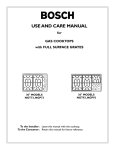
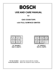
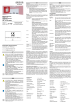
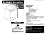
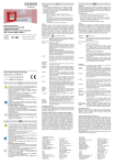
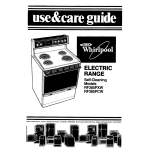
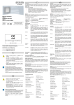
BOSCH
INSTALLATION
INSTRUCTIONS
MANUAL
STEEL GAS COOKTOPS
with FULL-SURFACE
GRATES
30" MODELS: NGT73, NGP73
36" MODELS: NGT93, NGP93
PLEASE
READ
INSTRUCTION
IMPORTANT:
INSTALLER:
Safety
•
must conform
Installation
Please retain these instructions for future
Instructions
with
local codes or, in
the absence of local codes, with the National
Gas Code,ANSI
•
Fuel
Z223. I.
the National
Electrical CocleANSI/
NFPA 70, latest edition. (In Canada, installation must
be in accordance with the CAN I-BI49.1 and .2
Installation
Codes for Gas BurningAppliances
and/
This appliance
has been tested in accordance
ANS Z2 I. I, Standard for Household
pliances (USA) and in accordance
Interim
Reqt
TO PREVENT
ELECTRICAL
GROUND
PRONG SHOULD
CIRCUMSTANCES,
MUST BE PLUGGED
RECTLY POLARIZED
If there
#58
Domestic
CONNECTEDTOA
120-VOLT CIRCUIT.
grounded,
by a qualified
A separate
which is in compliance
is any doubt as to whether
is property
COR-
the
the wall receptacle
customer
should
have it
electrician.
CAUTION:
Before you plug in an electrical cord,
be sure all controls are in the OFF position.
with
CooldngAp-
with CANI.I-M8
Gas
SHOCK, THE THIRD
NOT UNDER ANY
BE CUT OR REMOVED.
IT
INTO A MATCHING
GROUND-
circuit is recommended
with the NEC.
checked
or local codes )
•
reference.
ING TYPE RECEPTACLEAND
The appliance must be electrically grounded in accordance with local codes or, in the absence of
local codes,with
PROCEEDING
Save these instructions for the local electrical inspector's use.
Please leave these Installation Instructions
with this unit for the owner.
OWNER:
Important
BEFORE
I
Gas Requirements
Supply Pressure
Cool<tops
Natural Gas - 6 inches water column
(CANADA).
(14.9 Millibars) minimum.
A
WARNING:
Improper
installation,
adjustment, alteration,
service
or mainte-
nance can cause injury or property damage. Refer to this manual. For assistance or additional
information
consult a qualified
agency, manufacturer
Propane Gas (27.4 Millibars)
I I inches water column
minimum.
The maximum
gas pressure
exceed
14.0 inches water
PROPANE
installer, service
or the gas supplier.
to this appliance
column
is not to
(34.9 MB).
GAS INSTALLATION
The propane
gas tank must be equipped
high pressure regulator
in addition
with
its own
to the pressure regu-
lator supplied with this unit.
•
The cool<top must be used in conjunction with
suitable ventilation
a
system.
The cool<top
natural
is shipped from the factory
gas. For use with
LR
quired and must be purchased
Power Requirements
and Grounding
Power Supply: 120Volts, IS Ampere, 60 Hz.This appliance is
factory equipped with a S-foot power supply cord with a 3prong grounding plug (with polarized parallel blades).
for use with
a conversion
kit is re-
separately. Contact
BSH
or your retailer to obtain Idt # NEZI065.
A qualified
technician or installer must do the conversion.
Leak testing
according
of the appliance
to manufacturer's
Do Not Discard This Sheet
shall be conducted
instructions.
CABINET
CONSIDERATIONS
Dimension requirements
& 2 are for combustible
When
in Figs. I
surfaces.
the surface is protected
material
Protector
Figure
AND
I - Installed
COUNTERTOP
Dimensions
MSG
Hood
listed by UL as a Floor
and Wall Shield and is
with not less than No. 28
sheet
stainless
metal,
steel,
or
0.015-inch
•
0.024-inch
_
Counter
Left Side
_-M_n.
- 30" Min_to
Surface
NGT(P)73- - 36"
30" Min.
Min.
NGT(P)93
÷
Centered
18_""
'_
is
. _.
•
Over Cooktop
Rear Wall *1-3/4"
Io
dimensions may be reduced. For a
noncombustible
surface over the
clearance
edges)
Depth - 24" Max.
Combustible
aluminum or copper, it is considered
noncombustible
and
some
cool<top, the minimum
24" rather than 30".
cool<top
Depth from Back Wall
Cabinet !3" Max.
by a
Above
covered
(from
CUTOUT
._
o IIo
0
Right Side
3" Min.
o I
0
Cool<top to frontof countertop - I-I/4"minimum
Instructions
are
based
on
standard American
cabinets 36"
high
with
x 24"
deep
Dimensions
NOTICE:
approximately
a 10-
square-inch opening in the toe
kid< area or other cabinet area
for adequate
cabinet.
Figure
air
inlet
clearances
to combustible
materials
a 25"
countertop.
Provide
are minimum
to
the
All measurements
Plan the installation
of the unit so
given in Figures I and 2 have to
be precisely followed. If nonstandard
cabinets are used,
that the power
cord, gas shut-off
make sure they are installed with
minimum dimensions shown in
Ifa drawer is installed directly
Fig. I and Fig. 2.
bad<) should be no greater than 15".
valve and gas pressure regulator are
accessible from the front of cabinet.
the
cool<top,
its depth
(front
2
1-3/4" Min, to Combustible Rear Walt
_3"
Min, to Right
Side Wail
21" Cooktop Depth
1/8" Min.
Clearance
From
Cooktop to
Start of
Radius
2-1/4" Min. to
"_
A '
Cut-out
30" Models
19-1/8 to
19-7/8"
36" Models
19-1/8" to
19-718"
B
Cut-out
28-5/8" to
29-3/8"
34-5/8" to
35-3/8"
C
Corner
Cutout
Dimensions
are Underlined
D
Overall
PAGE 2
30"
36"
31"
37"
under
to
INSTALLING
THE COOKTOP
I. Seal the Cool(top
Figure
Apply the foam tape packaged with
the cooktop
Important:
along the perimeter
before
For solid surface material
and Corian ®, consult
reflective
with
the cooktop
installing.
installations
solid surface
to underside
of
See Fig. 3.
cutout
-
solid surface
TM
heat
Foil Tape #425 or #427
tape such as Scotch®Aluminum
Counter
countertops
such as Surel
manufacturer.Apply
3
:'
!_
A
_':_ i_
Cutout
shows
L.._jA
location
of Aluminum
Reflective
Tape
around the cutout so that it folds over on the top and sides. DO
NOTWRAPTHETAPE
UNDERNEATH
THE COOKTOR
Be sure
the tape extends
beyond
the outermost
flange of the cooktop.All
Heat Reflective
corners
Tape
should be covered with tape. See Fig 3.
2. Attach
Attach
Brackets
to the
Cool(top
clamps of the hold-down
top to the rough-in
Figure
brackets
_
Section
packaged with the cool(-
box. Use the washers and screws provided.
:2,.:__
'A - A"
4
Attaching
hold-down
brackets
See
Fig. 4.
3. Install
Insert
the Cool(top
cool<top
sired position
into the cutout.Adjust
and tighten
hold-down
screws to rough-in
screw into clamp and secure cooktop
brackets
to de-
box. Insert adjusting
to countertop.
See Fig. 4.
'
i
_,_Adjusting
Important: For solid surface material installations, insert a wooden
block between the end of the screw and the bottom of the countertop.
Do not overtighten
cess aluminum
4. Connect
tape around
adjusting
screw. See Figure 4.Trim
cooktop
flange.
sible location
of manifold
regulator,
tion.
CAUTION:
installing a gas shut-off
under
(supplied)
pipe.To
the unit
lator, except for conversion
Connect
possible
box is in its permanent
any adjustment
sure regulator.
(See complete
of the pressure
regu-
Figure
6
Gas and electrical
wall shut-off
procedure
for 30" models - 12-5/8"
for 36" models - t2-1/2"
posi-
to propane.
between
)Ct_ulout
damage to the gas pressure
the gas supply line to the unit pressure
I/2" flex gas line connector
box.
valve in an easily acces-
pipe usingTeflon ® tape on threads
install it after the rough-in
Do not attempt
Box area.
(see Figure 6), install the pressure
to manifold
prevent
5
Opening for Gas
Connection &
Electrical Cord
Gas Supply
See Figure 5.After
Figure
" _
Rough-in
The gas inlet to the unit is located at the right rear of rough-in
regulator
ex-
Screw
regulator
using a
..g"
location.
L
valve and pres-
1/2" Female
. Pipe Threads
in Figure 6.)
-Supply Cord
120V
PLof Wall
Receptacle
Continued
next
page
Gas Slubeut
PAGE 3
Secure regulator
to cooktop
gas inlet using approved
Teflon ® tape. Turn to hand tighten
exceeding
one turn
plus
For
I/4 turn, not
I. Shut-off
for alignment.
for leaks using a soap solution.
Notes
The appliance
for Gas Connection:
and its individual
be disconnected
ing any pressure
5. Connect
gas shutoff valve must
from the gas supply piping system durtesting
of that system
at test pres-
sures in excess of I/2 psi (3.SkPa).
valve must be a "T"
Before
must not be longer
Electrical
connecting
Supply
5-foot
supply cord
to wall recep-
tacle, make certain that gas shutoff valve and all burner
controls
are in OFF position.
6. Final Check
The appliance must be isolated from the gas supply pip-
After
ing system by closing its individual
manual shut-offvalve
electrical
connection
burner
cap in correct
during any pressure testing of the gas supply piping sys-
eration
of electric
tem at test
Flame should
pressures
handle gas cock.
3. Not approved for installation in a bedroom
or a bathroom
unless unit is direct vent.
Do not use a
flame of any sort.
Important
Installations:
2. Flexible gas connector
than 36 inches.
Turn on gas at shut-off valve and check supply line connections
Massachusetts
equal to or less than
I/2 psi
is complete,
notched
position
place
each
and check op-
igniters. Check flame characteristics.
be blue with no yellow
tip.
(3.SkPa).
Check Use & Care manual for troubleshooting
mation.
For technical
For the most
service
up to date critical
questions
contact
Customer
dimensions
by fax, use your
Use code # 8317.
Service
infor-
at 8001944-2904.
fax handset
and call 775-833-3600.
We reserve the right to change specifications or design without notice. Some models are certified for use in Canada. BSH Home
Appliances Corp. is not responsible for products which are transported from the U.S. for use in Canada. Check with your local
Canadian distributor or dealer.
Note:The
Bosch cool<top referred to throughout
this manual is manufactured
by BSH Home Appliances Corp.
BOSCH
5551 McFadden Avenue, Huntington
Beach, CA 92649 ° 800/944-2904
© 2002 BSH Home Appliances Corp. ° Litho/U.S.A. 01/02
50 60 00 36 17 (8201)
PAGE 4