1
®
OmniSwitch 6600 Family
Getting Started Guide
060178-10, Rev. E
March 2005
Warning. Only personnel knowledgeable in basic electrical and mechanical procedures should install or maintain this
equipment.
Lithium Batteries Caution. There is a danger of explosion if the Lithium battery in your chassis is incorrectly replaced.
Replace the battery only with the same or equivalent type of battery recommended by the manufacturer. Dispose of used
batteries according to the manufacturer’s instructions. The manufacturer’s instructions are as follows:
Return the module with the Lithium battery to Alcatel. The Lithium battery will
be replaced at Alcatel’s factory.
The features and specifications described in this guide are subject to change without notice.
Copyright © 2005 by Alcatel Internetworking, Inc. All rights reserved. This document may not be reproduced in whole or in
part without the express written permission of Alcatel Internetworking, Inc.
Alcatel® and the Alcatel logo are registered trademarks of Alcatel. Xylan®, OmniSwitch®, OmniStack®, and
Alcatel OmniVista® are registered trademarks of Alcatel Internetworking, Inc.
OmniAccess™, Omni Switch/Router™, PolicyView™, RouterView™, SwitchManager™, VoiceView™, WebView™,
X-Cell™, X-Vision™, and the Xylan logo are trademarks of Alcatel Internetworking, Inc.
This OmniSwitch product contains components which may be covered by one or more of the following U.S. Patents:
• U.S. Patent No. 6,339,830
• U.S. Patent No. 6,070,243
• U.S. Patent No. 6,061,368
• U.S. Patent No. 5,394,402
• U.S. Patent No. 6,047,024
• U.S. Patent No. 6,314,106
Alcatel Internetworking
• U.S. Patent No. 6,542,507
26801 West Agoura Road
Calabasas, CA 91301
(818) 880-3500 FAX (818) 880-3505
US Customer Support: (800) 995-2696
International Customer Support: (818) 878-4507
Internet: http://eservice.ind.alcatel.com
Table of Contents
OmniSwitch 6600 Family. . . . . . . . . . . . . .
1
OS6602-48 . . . . . . . . . . . . . . . . . . . . . . . . . .7
Features . . . . . . . . . . . . . . . . . . . . . . . . . . . . . . . . . . . 1
Items Included . . . . . . . . . . . . . . . . . . . . . . . . . . . . . . 7
Optional Items . . . . . . . . . . . . . . . . . . . . . . . . . . .8
Stand-Alone and Stacked
Configurations . . . . . . . . . . . . . . . . . . . . . . . . . . . . . 1
Stand-Alone . . . . . . . . . . . . . . . . . . . . . . . . . . . . 1
Stacked Configurations . . . . . . . . . . . . . . . . . . . . 2
Availability Features . . . . . . . . . . . . . . . . . . . . . . . . 2
Chassis Types . . . . . . . . . . . . . . . . . . . . . . . . . . . . . . 3
OmniSwitch 6624 (OS6624) . . . . . . . . . . . . . . . 3
OmniSwitch 6648 (OS6648) . . . . . . . . . . . . . . . 3
OmniSwitch 6600-U24 (OS6600-U24) . . . . . . . 4
OmniSwitch 6600-P24 (OS6600-P24) . . . . . . . . 4
OmniSwitch 6602-24 (OS6602-24) . . . . . . . . . . 5
OmniSwitch 6602-48 (OS6602-48) . . . . . . . . . . 5
Setting Up the Hardware . . . . . . . . . . . . . .
Unpacking and Initial Setup . . . . . . . . . . . . . . . . . . . 8
Unpacking the Chassis . . . . . . . . . . . . . . . . . . . .8
Recommendations . . . . . . . . . . . . . . . . . . . .8
Instructions . . . . . . . . . . . . . . . . . . . . . . . . . .9
Setting Up the Switch . . . . . . . . . . . . . . . . . . . . . . . . 9
Airflow Considerations . . . . . . . . . . . . . . . . . . . .9
Installing the Switch on a Tabletop or Bench . .10
Rack-Mounting the Switch . . . . . . . . . . . . . . . .11
Rack Mounting Stacked Configurations . . . . . .13
Installing a Back Up Power Supply
(OS6624, OS6648, OS6600-U24) . . . . . . . . . . . . . 14
6
Installing Uplink and Stacking Modules . . . . . . . . . 16
Items Required . . . . . . . . . . . . . . . . . . . . . . . . . . . . . 6
Installing MiniGBIC Connectors . . . . . . . . . . . . . . 18
Site Preparation . . . . . . . . . . . . . . . . . . . . . . . . . . . . 6
Environmental Requirements . . . . . . . . . . . . . . . 6
Electrical Requirements . . . . . . . . . . . . . . . . . . . 6
Weight Considerations . . . . . . . . . . . . . . . . . . . . 7
OS6624 . . . . . . . . . . . . . . . . . . . . . . . . . . . . 7
OS6648 . . . . . . . . . . . . . . . . . . . . . . . . . . . . 7
OS6600-U24 . . . . . . . . . . . . . . . . . . . . . . . . 7
OS6600-P24 . . . . . . . . . . . . . . . . . . . . . . . . . 7
OS6602-24 . . . . . . . . . . . . . . . . . . . . . . . . . . 7
Installing SFP Connectors
(OS6600-U24 Only) . . . . . . . . . . . . . . . . . . . . . . . . 20
March 2005
Blank Cover Plates . . . . . . . . . . . . . . . . . . . . . . . . . 21
Connections and Cabling
. . . . . . . . . . . . . 22
Connecting the Serial Cable to the Console Port . . 22
Serial Connection Default Settings . . . . . . . . . .22
The Next Step . . . . . . . . . . . . . . . . . . . . . . . . . . . . . 23
iii
Completing a Stacked
Configuration . . . . . . . . . . . . . . . . . . . . . . . . . . . .
Assigning Slot Numbers . . . . . . . . . . . . . . . . . . . . . . . . 25
Setting Optional System Information . . . . . . . . . . . 37
Specifying an Administrative Contact . . . . . . .37
Specifying a System Name . . . . . . . . . . . . . . . .37
Specifying the Switch’s Location . . . . . . . . . . .37
Slot Numbering Example . . . . . . . . . . . . . . . . . . . . 26
Viewing Your Changes . . . . . . . . . . . . . . . . . . . . . . 38
Connecting Cables
to Stacking Modules . . . . . . . . . . . . . . . . . . . . . . . . . . . 27
Saving Your Changes . . . . . . . . . . . . . . . . . . . . . . . 38
Guidelines . . . . . . . . . . . . . . . . . . . . . . . . . . . . . . . . 27
CLI Basics . . . . . . . . . . . . . . . . . . . . . . . . . . . . . . . . . . . 41
Booting the Stack . . . . . . . . . . . . . . . . . . . . . . . . . . . . . 29
CLI Assistance Features . . . . . . . . . . . . . . . . . . . . . 41
Syntax Checking . . . . . . . . . . . . . . . . . . . . . . . .41
Command Line (?) Help . . . . . . . . . . . . . . . . . .42
Partial Keyword Completion . . . . . . . . . . . . . . .42
Deleting Characters . . . . . . . . . . . . . . . . . . . . . .42
Inserting Characters . . . . . . . . . . . . . . . . . . . . .43
Previous Command Recall . . . . . . . . . . . . . . . .43
Prefix Recognition . . . . . . . . . . . . . . . . . . . . . .43
Prefix Prompt . . . . . . . . . . . . . . . . . . . . . . . . . .44
Command History . . . . . . . . . . . . . . . . . . . . . . .44
Command Logging . . . . . . . . . . . . . . . . . . . . . .45
Enabling Command Logging . . . . . . . . . . .45
24
Slot Assignment Guidelines . . . . . . . . . . . . . . . 24
Booting Stand-Alone Switches . . . . . . . . . . . . . . . . . . . 29
Verifying LED Status . . . . . . . . . . . . . . . . . . . .
30
Component LEDs . . . . . . . . . . . . . . . . . . . . . . . . . . 30
Verifying Primary and Secondary Status . . . . . 30
PRI LED . . . . . . . . . . . . . . . . . . . . . . . . . . 30
SEC LED . . . . . . . . . . . . . . . . . . . . . . . . . . 31
Idle Status . . . . . . . . . . . . . . . . . . . . . . . . . 31
Your First Login Session . . . . . . . . . . . . . . .
32
Logging In to the Switch . . . . . . . . . . . . . . . . . . . . 32
Assigning an IP Address to the Switch or Stack . . 33
Assigning IP Addresses to Switches in a
Stacked Configuration . . . . . . . . . . . . . . . . . . . 34
Unlocking Session Types . . . . . . . . . . . . . . . . . . . . 34
Unlocking All Session Types . . . . . . . . . . . . . . 34
Unlocking Specified Session Types . . . . . . . . . 35
How many sessions are allowed? . . . . . . . . . . . 35
Changing the Login Password . . . . . . . . . . . . . . . . 35
Modifying the Serial Connection Settings . . . . . . . 38
Common CLI Commands . . . . . . . . . . . . . . . . . . . . 46
Offline Configuring . . . . . . . . . . . . . . . . . . . . . . . . . . . . 47
Syntax Checking . . . . . . . . . . . . . . . . . . . . . . . .47
Scheduling a Configuration File to be Applied
at a Later Time . . . . . . . . . . . . . . . . . . . . . . . . .47
Generating Snapshots of the
Current Configuration . . . . . . . . . . . . . . . . . . . . . . . 47
Setting the System Time Zone . . . . . . . . . . . . . . . . 36
Setting the Date and Time . . . . . . . . . . . . . . . . . . . 36
iv
March 2005
Files and Directories . . . . . . . . . . . . . . . . . . . .
48
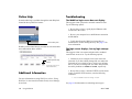
Online Help . . . . . . . . . . . . . . . . . . . . . . . . . . . . . . . 60
Boot and Image Files . . . . . . . . . . . . . . . . . . . . . . . . . . . 48
Additional Information . . . . . . . . . . . . . . . . . . . . . . 60
boot.params File . . . . . . . . . . . . . . . . . . . . . . . . . . . 48
Troubleshooting . . . . . . . . . . . . . . . . . . . . . . . . . . . 60
The WebView login screen does not
display. . . . . . . . . . . . . . . . . . . . . . . . . . . .60
The login screen displays, but my login
attempt fails. . . . . . . . . . . . . . . . . . . . . . . .60
boot.cfg File . . . . . . . . . . . . . . . . . . . . . . . . . . . . . . 48
boot.slot.cfg File . . . . . . . . . . . . . . . . . . . . . . . . . . . 49
Image Files . . . . . . . . . . . . . . . . . . . . . . . . . . . . . . . 49
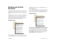
Working and Certified Directories . . . . . . . . . . . . . . . . 51
Working Directory . . . . . . . . . . . . . . . . . . . . . . 51
Certified Directory . . . . . . . . . . . . . . . . . . . . . . 51
How can I tell which directory the switch
is currently using? . . . . . . . . . . . . . . . . . . . 52
Can I save changes to the Certified
directory? . . . . . . . . . . . . . . . . . . . . . . . . . . . . . 52
What happens when the switch boots? . . . . . . . 52
Working and Certified Are Identical . . . . . . . . 52
Working and Certified Are Different . . . . . . . . 53
My Working and Certified directories are
different. Can I force a reboot from the
Working directory? . . . . . . . . . . . . . . . . . . 53
Loading Software . . . . . . . . . . . . . . . . . . . . . . .
Hardware Basics . . . . . . . . . . . . . . . . . . . . . . . . 61
OmniSwitch 6624 Front Panel . . . . . . . . . . . . . . . . 61
OmniSwitch 6600-U24 Front Panel . . . . . . . . . . . . 62
OmniSwitch 6648 Front Panel . . . . . . . . . . . . . . . . 63
OmniSwitch 6600-P24 Front Panel . . . . . . . . . . . . 64
OmniSwitch 6602-24 Front Panel . . . . . . . . . . . . . . 65
OmniSwitch 6602-48 Front Panel . . . . . . . . . . . . . . 66
OmniSwitch 6600 Status LEDs . . . . . . . . . . . . . . . 67
54
Stand-Alone Configurations . . . . . . . . . . . . . . . . . . 54
Stacked Configurations . . . . . . . . . . . . . . . . . . . . . 55
Certifying Your New Software . . . . . . . . . . . . . 56
Using WebView
. . . . . . . . . . . . . . . . . . . . . . . . . 57
Browser Compatibility . . . . . . . . . . . . . . . . . . . . . . 57
Required Image Files . . . . . . . . . . . . . . . . . . . . . . . 57
Logging In to WebView . . . . . . . . . . . . . . . . . . . . . 58
Navigating WebView . . . . . . . . . . . . . . . . . . . . . . . 58
March 2005
v
vi
March 2005
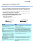
OmniSwitch 6600 Family
Features
The OmniSwitch 6600 Family (OS6624, OS6600-U24,
OS6648, OS6600-P24, OS6602-24, and OS6602-48) are next
generation enterprise edge/workgroup switches. These
switches are based on the same software architecture as
OmniSwitch 7000 and 8000 series switches (i.e., OS7700,
OS7800, and OS8800). These switches are designed to meet
the most stringent network requirements for mission-critical
networks.
OmniSwitch 6600 Family switches are optimized for voice
and data integration and provide non-blocking multi-Gigabit
Ethernet capacity. Additional features include Carrier-class
intelligence, best of breed QoS, Carrier-class resiliency,
network management, and advanced policy-based VLANs and
security. OmniSwitch 6600 Family switches also support wirespeed Layer 2 and Layer 3 switching, industry-based standards, and a full array of reliability, redundancy and resiliency
capabilities.
March 2005
Stand-Alone and Stacked
Configurations
Stand-Alone
A stand-alone OmniSwitch 6600 Family switch is ideal for
small and medium-sized network edge applications, offering
24 10/100 ports (OS6624 and OS6602-24), 24 Power over
Ethernet (PoE) ports (OS6600-P24), 48 10/100 (OS6648 and
OS6602-48) ports, and 24 100 SFP ports (OS6600-U24).
These switches provide support for enterprise-based devices,
such as computer workstations or IP telephones.
A single OmniSwitch 6600 Family also supports two Gigabit
Ethernet uplinks for high-bandwidth connections to a backbone or server.
OmniSwitch 6600 Family
1
Stacked Configurations
Availability Features
In addition to working as individual, stand-alone switches,
OmniSwitch 6600 Family switches can also be linked together
to form a single, high-density virtual chassis known as a stack.
The OmniSwitch 6600 Family provides a broad variety of
Availability features. Availability features are hardware- and
software-based safeguards that help prevent the loss of data
flow in the event of a subsystem failure.
Stacking switches provides scalability by allowing users to
quickly and easily expand 10/100 port density. Twenty-four
10/100 ports are added for each OS6624 brought into the
stack; twenty-four 100 SFP ports are added for each OS6600U24; forty-eight 10/100 ports are added for each OS6648.
Up to eight switches can be stacked. OmniSwitch 6600 Family
switches can be mixed and matched in any combination within
the stack. This provides a virtual chassis with a 10/100 or 100
capacity of up to 384 ports.
As with the stand-alone configuration, a stacked virtual chassis configuration provides Gigabit Ethernet uplinks to a backbone or server.
Note. For basic information on stacking OmniSwitch 6600
Family switches into a virtual chassis, refer to
“Completing a Stacked Configuration” on page 24.
For additional information, refer to the OmniSwitch
6600 Family Hardware Users Guide.
2
OmniSwitch 6600 Family
In addition, some Availability features allow you to maintain
or replace hardware components without powering off your
switch or interrupting switch operations.
Combined, these features provide added resiliency and help
ensure that your switch is consistently available for your dayto-day network operations.
Hardware-related Availability features include:
• Smart Continuous Switching
• Software Rollback
• Hot Swapping
• Hardware Monitoring
For information on these Availability features, refer to the
OmniSwitch 6600 Family Hardware Users Guide.
March 2005
Chassis Types
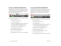
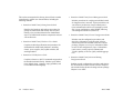
OmniSwitch 6648 (OS6648)
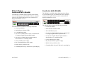
OmniSwitch 6624 (OS6624)
The OS6624 is a stackable edge/workgroup switch offering
24 10/100 Ethernet ports. The OS6624 can also be equipped
with up to four Gigabit Ethernet ports for connections to a
high speed backbone or server.
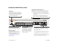
The OS6648 is a stackable edge/workgroup switch offering
48 10/100 Ethernet ports. The OS6648 can also be equipped
with up to four Gigabit Ethernet ports for connections to a
high speed backbone or server.
TM
25
27
29
31
33
35
37
39
41
43
45
47
26
1
28
3
30
5
32
7
34
9
36
11
38
13
40
15
42
17
44
19
46
21
48
23
2
4
6
8
10
12
14
16
18
20
22
24
OmniSwitch 6648
LINK/ACT
CONSOLE
TM
CONSOLE
25
1
3
5
7
9
11
13
15
17
19
21
EXPANSION
26
EXPANSION/STACKING
27
28
2
4
6
8
10
12
14
16
18
20
22
50
51
LINK/ACT
LINK/ACT
52
EXPANSION
OK1 PS1 PRI TEMP
OK2 PS2 SEC FAN
LINK/ACT
SEL
49
LINK/ACT
23
OK1 PS1 PRI TEMP
OK2 PS2 SEC FAN
LINK/ACT
EXPANSION/STACKING
OmniSwitch 6624
SEL
LINK/ACT
LINK/ACT
24
The OS6624 chassis contains the following components:
• Console port (DB-9)
• Stack indicator and status LEDs
• 24 10/100 Ethernet ports
• One slot for OS6600-GNI-U2 (fiber) or OS6600-GNI-
C2 (copper) Gigabit Ethernet uplink module
• One slot for a Gigabit Ethernet uplink module as
described above or a stacking module
• Factory-installed power supply
• Bay for optional back up power supply
• Built-in fan tray with three fans
The OS6648 chassis contains the following components:
• Console port (DB-9)
• Stack indicator and status LEDs
• 48 10/100 Ethernet ports
• One slot for OS6600-GNI-U2 (fiber) or OS6600-GNI-
C2 (copper) Gigabit Ethernet uplink module
• One slot for a Gigabit Ethernet uplink module as
described above or a stacking module
• Factory-installed power supply
• Bay for optional back up power supply
• Built-in fan tray with three fans
• Grounding block for type LCD8-10A-L grounding lug
• Grounding block for type LCD8-10A-L grounding lug
March 2005
OmniSwitch 6600 Family
3
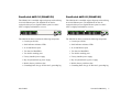
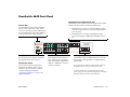
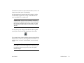
OmniSwitch 6600-U24 (OS6600-U24)
OmniSwitch 6600-P24 (OS6600-P24)
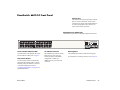
The OS6600-U24 is a stackable edge/workgroup switch offering 24 100 SFP Ethernet ports. The OS6600-U24 can also be
equipped with up to four Gigabit Ethernet ports for connections to a high speed backbone or server.
The OS6600-U24 is a stackable edge/workgroup switch offering 24 Power over Ethernet (PoE) 10/100 Ethernet ports. The
OS6600-P24 can also be equipped with up to four Gigabit
Ethernet ports for connections to a high speed backbone or
server.
TM
OmniSwitch 6600-U24
3
1
5
7
9
11
13
15
17
19
21
23
25
EXPANSION
26
EXPANSION/STACKING
27
28
TM
CONSOLE
SEL
2
OK1
PS1
OK2
PS2 PRI SEC FAN TEMP
24
1
2
3
4
5
6
7
8
9
10
11
12
13 14
15
16
17
18
19
20
21
22
23
LINK/ACT
OmniSwitch 6600-P24
25
LINK/ACT
1
24
3
5
7
9
11
13
15
17
19
21
EXPANSION
26
EXPANSION/STACKING
27
28
23
CONSOLE
OK1
PS1
OK2
PS2
SEL
LINK/ACT
PRI SEC FAN TEMP
2
4
6
8
10
12
14
16
18
20
22
LINK/ACT
LINK/ACT
LINK/ACT
24
The OS6600-U24 chassis contains the following components:
• Console port (RJ-45)
• Stack indicator and status LEDs
• 24 100 Ethernet SFP ports
• One slot for OS6600-GNI-U2 (fiber) or OS6600-GNI-
C2 (copper) Gigabit Ethernet uplink module
• One slot for a Gigabit Ethernet uplink module as
described above or a stacking module
• Factory-installed power supply
• Bay for optional back up power supply
• Built-in fan tray with three fans
• Grounding block for type LCD8-10A-L grounding lug
The OS6600-U24 chassis contains the following components:
• Console port (RJ-45)
• Stack indicator and status LEDs
• 24 10/100 PoE ports
• One slot for OS6600-GNI-U2 (fiber) or OS6600-GNI-
C2 (copper) Gigabit Ethernet uplink module
• One slot for a Gigabit Ethernet uplink module as
described above or a stacking module
• Factory-installed power supply
• Connector for optional back up power supply
• Built-in fan tray with three fans
• Grounding block for type LCD8-10A-L grounding lug
4
OmniSwitch 6600 Family
March 2005
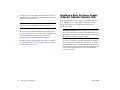
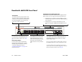
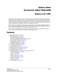
OmniSwitch 6602-24 (OS6602-24)
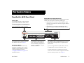
OmniSwitch 6602-48 (OS6602-48)
The OS6602-24 is a stackable edge/workgroup switch offering
24 10/100 Ethernet ports. The OS6602-24 can also be
equipped with up to two Gigabit Ethernet ports for connections to a high speed backbone or server.
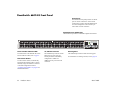
The OS6602-48 is a stackable edge/workgroup switch offering
48 10/100 Ethernet ports. The OS6602-48 can also be
equipped with up to two Gigabit Ethernet ports for connections to a high speed backbone or server.
1
2
3
4
5
6
7
8
9
10
1
11
12
13
14
15
16
17
18
19
20
21
22
23
24
TM
1
OmniSwitch 6602-24
25
C
o
n
s
o
l
e
1
3
4
5
6
7
8
9
10
11
12
13
14
15
16
17
18
19
20
21
22
23
24
25
26
28
29
30
31
32
33
34
35
36
37
38
39
40
41
42
43
44
45
46
47
48
TM
OmniSwitch 6602-48
OK1 PS1 PR1 TMP
OK2 PS2 SEC FAN
27
28
Stack
2
2
Sel
26
CLASS 1 LASER PRODUCT
The OS6602-24 chassis contains the following components:
49
C
o
n
s
o
l
e
Sel
OK1 PS1 PR1 TMP
OK2 PS2 SEC FAN
50
2
51
52
Stack
CLASS 1 LASER PRODUCT
The OS6602-24 chassis contains the following components:
• Console port (RJ-45)
• Console port (RJ-45)
• Stack indicator and status LEDs
• Stack indicator and status LEDs
• 24 10/100 Ethernet ports
• 48 10/100 Ethernet ports
• Two slots for MiniGBICs
• Two slots for MiniGBICs
• Two built-in stacking ports
• Two built-in stacking ports
• Factory-installed power supply
• Factory-installed power supply
• Bay for optional back up power supply
• Bay for optional back up power supply
• Built-in fan tray with three fans
• Built-in fan tray with three fans
• Grounding block for type LCD8-10A-L grounding lug
• Grounding block for type LCD8-10A-L grounding lug
March 2005
OmniSwitch 6600 Family
5
Setting Up the Hardware
Items Required
Electrical Requirements
In addition to the materials and components provided in the
OmniSwitch 6600 Family shipment, you must provide the
following items in order to complete this installation:
OmniSwitch 6600 Family switches have the following general
electrical requirements:
• Grounding wrist strap
• Phillips screwdriver
• Serial cable
• Rack mount screws, if applicable
• Each switch requires one grounded AC power source
for each power supply installed in the chassis .
• Grounded AC power source must be 110V for North
American installations (220V international).
• Each supplied AC power cord is 2 meters (approxi-
mately 6.5 feet) long. Do not use extension cords.
Site Preparation
Environmental Requirements
OmniSwitch 6600 Family switches have the following environmental and airflow requirements:
• The installation site must maintain a temperature
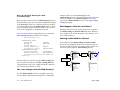
Redundant Circuit Recommendation. If possible, it is
recommended that the primary and back up power
supplies are plugged into AC sources on separate circuits.
With redundant AC, if a single circuit fails, the switch’s
back up power supply (on a separate circuit) will likely be
unaffected and can therefore continue operating.
between 0° and 45° Celsius (32° and 122° Fahrenheit)
and not exceed 95 percent maximum humidity (noncondensing) at any time.
• Be sure to allow adequate room for proper air ventila-
tion and access at the front, back, and sides of the
switch. No clearance is necessary at the top or bottom
of the chassis. Refer to “Airflow Considerations” on
page 9 for minimum clearance requirements.
6
Setting Up the Hardware
March 2005
Weight Considerations
OS6624
A stack of eight OS6600-P24 switches—without back up
power supplies— weighs approximately 96 lbs (36 Kgs).
OS6602-24
With a back up power supply installed, a single OS6624
weighs approximately 13.5 lbs (6.1 Kgs).
Without a back up power supply installed, a single OS6602-24
weighs approximately 12 lbs (4.5 Kgs).
A stack of eight OS6624 switches—fully populated with
uplink and stacking modules and back up power supplies—
weighs approximately 108 lbs (49.1 Kgs).
A stack of eight OS6602-24 switches—without back up power
supplies— weighs approximately 96 lbs (36 Kgs).
OS6648
OS6602-48
With a back up power supply installed, a single OS6648
weighs approximately 15.5 lbs (6.8 Kgs).
Without a back up power supply installed, a single OS6602-48
weighs approximately 12 lbs (4.5 Kgs).
A stack of eight OS6648 switches—fully populated with
uplink and stacking modules and back up power supplies—
weighs approximately 124 lbs (56.4 Kgs).
A stack of eight OS6602-48 switches—without back up power
supplies— weighs approximately 96 lbs (36 Kgs).
OS6600-U24
Items Included
With a back up power supply installed, a single OS6600-U24
weighs approximately 13.06 lbs (5.92 Kgs).
Your OmniSwitch 6600 Family switch order includes the
following items:
A stack of eight OS6600-U24 switches—with back up power
supplies— weighs approximately 104.48 lbs (47.36 Kgs).
OS6600-P24
Without a back up power supply installed, a single OS6600P24 weighs approximately 12 lbs (4.5 Kgs).
• OmniSwitch chassis
• Blank cover panels for empty uplink module and
backup power supply bays
• Rack mount flanges with attachment screws
• Grounding wrist strap
• Power cord (country-specific)
March 2005
Setting Up the Hardware
7
• Hardcopy OmniSwitch 6600 Family Getting Started
• SFP-100-LC-MM, SFP-100-LC-SM, or SFP-100-MTRJ
Guide (OS6624, OS6648, OS6600-U24, OS6600-P24
only)
100 Mbps SFPs (OS6600-U24 only)
• Documentation CD containing the following
OmniSwitch 6600 Family-specific manuals:
OmniSwitch 6600 Family Getting Started Guide
OmniSwitch 6600 Family Hardware Users Guide
OmniSwitch CLI Reference Guide
• Stacking kit (includes one stacking module and
30 centimeter cable)
• Redundant stacking kit (includes one stacking module
and one-meter cable)
Unpacking and Initial Setup
Unpacking the Chassis
OmniSwitch 6600 Family Switch Management Guide
OmniSwitch 6600 Family Network Configuration
Guide
To protect your OmniSwitch chassis and hardware components from electrostatic discharge (ESD) and physical damage,
read all unpacking recommendations and instructions carefully before beginning.
OmniSwitch 6600 Family Advanced Routing Configuration Guide
Recommendations
Optional Items
• Unpack your OmniSwitch chassis as close as possible
Depending on your order, the OmniSwitch shipment may also
include one or more of the following optional items:
• Depending on your order, uplink modules,
• Back up power supply
• OS6600-GNI-U2 or OS6600-GNI-C2 Gigabit Ethernet
uplink modules
to the location where it will be installed.
MiniGBICs, stacking modules, and SFPs may be packaged separately. In order to greatly reduce exposure to
electrostatic discharge (ESD) and physical damage, do
not unpack these items until they are ready to be
installed.
• MiniGBIC-SX, MiniGBIC-LX, or MiniGBIC-LH-70
Mini Gigabit Ethernet Interface Converters (for switches
using OS6600-GNI-U2 uplink modules only)
8
Setting Up the Hardware
March 2005
Instructions
1 Carefully cut the tape along the seam at the top of the
box containing the chassis.
2 Lift the box’s top flaps. Remove any smaller boxes or
Setting Up the Switch
Note. Due to their airflow and access requirements,
OmniSwitch 6600 Family switches cannot be wallmounted.
pouches that are enclosed and set them aside.
3 Lift the chassis out of the packaging.
Airflow Considerations
4 Carefully remove the foam pads and protective plastic
from the switch chassis.
Be sure that your switch is placed in a well-ventilated, staticfree environment. Always allow adequate clearance at the
front, rear, and sides of the switch.
Note. Alcatel provides factory-installed blank cover plates
for empty module slots. Because they play an important
role in chassis ventilation, do not remove these cover
plates unless a module or back up power supply is to be
installed immediately at the corresponding slot.
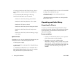
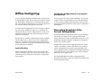
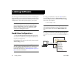
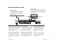
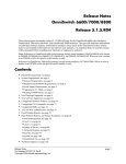
The following diagram shows recommended minimum clearances for adequate chassis airflow and access to components at
the rear of the chassis—e.g., back up power supply and power
switch(es).
5 If you are installing multiple switches in a stacked
Rear. 5 inches minimum
at rear of chassis for
installation and removal
of optional back up
power supply.
configuration, repeat steps 1 through 4 for the remaining
switches that will make up the stack.
6 Once all OmniSwitch 6600 Family switches have been
removed from their packaging, continue to “Setting Up
the Switch” on page 9.
Sides. 2 inches minimum
at left and right sides for
chassis airflow.
Front. 6 inches minimum
at front of chassis for
cable access and LED
visibility.
Chassis Top View
March 2005
Setting Up the Hardware
9
Never obstruct the air vents located at the left and right sides
of the chassis.
Note. Clearance is not required at the top and bottom of
the chassis. For detailed chassis airflow diagrams, refer to
the Hardware Users Guide.
There are two ways in which the OmniSwitch 6600 Family
can be installed:
• Tabletop installation
• Rack-mount installation
For information on setting up a switch as a tabletop unit, refer
to “Installing the Switch on a Tabletop or Bench” on page 10.
For information on rack-mounting the switch, refer to
“Rack-Mounting the Switch” on page 11.
Installing the Switch on a Tabletop or Bench
OmniSwitch 6600 Family switches can be installed freestanding as tabletop units. Locate your switch in a stable, flat, staticfree surface.
Note. OmniSwitch 6600 Family switches must be placed
“right side up.” Never attempt to operate a switch positioned on its side.
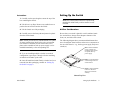
To install the switch as a tabletop unit, follow the steps below:
1 Position the chassis on the table or bench where it is to
be installed. Refer to page 7 for chassis weight considerations.
2 Be sure that adequate clearance has been provided for
chassis airflow and access to the front, back, and sides of
the switch. For recommended clearances, refer to page 9.
Also, be sure that you have placed the chassis within reach
of all required AC power sources. For environmental and
electrical requirements, refer to page 6.
3 If you are placing multiple switches in a stacked
configuration, carefully stack the remaining switches, one
on top of the other. Up to eight switches may be stacked to
form a single virtual chassis. Be sure to maintain adequate
clearance at the front, rear, left, and right side of all
switches.
4 Verify that the on/off switch for each OmniSwitch
6600 Family is in the off ( O ) position.
10
Setting Up the Hardware
March 2005
5 Plug the power cord (supplied) into the power socket
located on the switch’s rear panel; next, plug the cord into
an easily-accessible grounded AC power source. See
“Electrical Requirements” on page 6 for more information.
Note. Do not turn on the power supplies at this time. You
will power on all switches later in the setup process.
Note. If you are installing the switch in a 23-inch wide
rack, Alcatel offers optional 23-inch rack-mounting hardware. For more information, contact your Alcatel representative.
• Alcatel does not provide rack-mount screws. Use the
screws supplied by the rack vendor.
• To prevent a rack from becoming top heavy, it is
6 Continue to “Installing a Back Up Power Supply
recommended that you install heavier equipment at the
bottom of the rack whenever possible.
(OS6624, OS6648, OS6600-U24)” on page 14.
• If you are installing the switch in a relay rack, be sure
Rack-Mounting the Switch
Refer to the important guidelines below before installing the
OmniSwitch chassis in a rack.
to install and secure the rack per the rack manufacturer’s specifications.
• Review page 9 for important chassis airflow and access
recommendations before installing.
• It is recommended that two people install the switch in
the rack—one person to hold the chassis and position it
in the rack, and a second person to secure the chassis to
the rack using attachment screws (not supplied).
• Alcatel provides two rack-mount flanges with each
OmniSwitch 6600 Family switch. These flanges
support standard 19-inch rack mount installations.
These flanges must be attached to the chassis before
the switch can be rack mounted.
March 2005
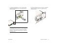
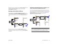
To rack-mount the switch, follow the steps below.
1 Align the holes in the provided rack-mount flanges
with the four threaded holes in the OmniSwitch chassis.
These threaded holes are located in the left and right sides
of the chassis, near the front panel.
Setting Up the Hardware
11
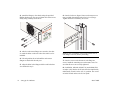
2 Attach the flanges to the chassis using the provided
6 Once the holes are aligned, insert a rack mount screw
Phillips-head screws. Be sure to tighten each of the screws
firmly using a Phillips screwdriver.
(not provided) through the bottom hole of each flange.
Tighten both screws until they are secure.
4
62
h6
tc
wi
niS
Om
TM
1
OK
2
OK
1
PS
2
PS
E
OL
NS
CO
P
EM
I T
PR
C
SE
L
SE
G
IN
CK
STA 5 2
N
FA
N/
SIO
N
PA
EX
51
50
N
7
SIO
49
N
PA
EX
8
3
4
3 After the rack-mount flanges are secured to the chas-
sis, mark the holes on the rack where the switch is to be
installed.
Note. Be sure to install the screws in the bottom hole of
each flange, as shown, before proceeding.
4 Lift and position the switch until the rack-mount
flanges are flush with the rack post.
7 Once the screws at the bottom of each flange are
5 Align the holes in the flanges with the rack holes that
secure, install the remaining two rack mount screws. Be
sure that all screws are securely tightened.
were marked in step 3.
8 On OS6624, OS6648, OS660-U24, and OS6600-P24
switches verify that the on/off switch for the OmniSwitch
6600 Family switch is in the off ( O ) position. The on/off
switch is located on the switch’s rear panel.
12
Setting Up the Hardware
March 2005
9 Plug the power cord (supplied) into the power socket
located on the switch’s rear panel; next, plug the cord into
an easily-accessible grounded AC power source. See
“Electrical Requirements” on page 6 for more information.
Note. Do not turn on the power supply at this time. You
will power on the switch later in the setup process.
Rack Mounting Stacked Configurations
If you are rack mounting multiple switches in a stacked
configuration, be sure to place all switches in verticallyadjacent rack positions. This will ensure that all required
stacking cables will have adequate length for the installation.
For additional instructions on rack mounting a stacked configuration, follow the steps below:
1 Install the rack mount flanges for all switches that are
10 If you wish to install a supplemental ground for the
switch, you may attach a type LCD8-10A-L grounding lug
to the grounding lug, located on the switch’s rear panel.
Install the type LCD8-10A-L grounding lug per manufacturer’s specifications.
11 If you are installing multiple switches in a rack to
form a stacked configuration, refer to “Rack Mounting
Stacked Configurations” on page 13. If you are not installing a stacked configuration, continue to “Installing a Back
Up Power Supply (OS6624, OS6648, OS6600-U24)” on
page 14.
to be included in the stacked configuration, as described
on page 11. Up to eight switches may be stacked to form a
single virtual chassis.
2 Place the next switch in the stack directly on top of the
previously installed switch.
3 Align the holes in the flanges with the holes in the
rack’s vertical posts.
4 Once the holes are aligned, insert a rack mount screw
through the bottom hole of each flange. Tighten both
screws until they are secure. Once the screws at the
bottom of each flange are secure, install the remaining two
rack mount screws. Be sure that all screws are securely
tightened.
5 Repeat steps 1 through 4 above for all remaining
switches.
6 On OS6624, OS6648, OS660-U24, and OS6600-P24
switches verify that the on/off switch for each
OmniSwitch 6600 Family switch is in the off ( O ) position.
March 2005
Setting Up the Hardware
13
7 Plug a power cord (supplied) into the power socket of
each switch; next, plug each cord into an easily-accessible
grounded AC power source.
Note. Do not turn on the power supplies at this time. You
will power on all switches later in the setup process.
8 If you wish to install a supplemental ground for each
switch, you may attach a type LCD8-10A-L grounding lug
to the grounding lug. Install the type LCD8-10A-L
grounding lug per manufacturer’s specifications.
14
Installing a Back Up Power Supply
(OS6624, OS6648, OS6600-U24)
If the optional back up power supply was included with your
order, install the power supply now by following the steps
below. The back up power supply bay is located at the
switch’s rear panel.
Anti-Static Warning. Before handling any components,
free yourself of static by wearing a grounding strap, or by
grounding yourself properly. Static discharge can damage
the switch and the back up power supply.
9 After you have rack-mounted your switches, continue
1 If there is a blank cover panel installed at the back up
to “Installing a Back Up Power Supply (OS6624, OS6648,
OS6600-U24)” on page 14.
power supply bay, uninstall it by removing the two Phillips attachment screws. After the attachment screws have
been removed, carefully pry the blank cover panel out and
away from the chassis. Set the cover panel and attachment screws aside.
Setting Up the Hardware
March 2005
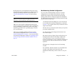
2 To avoid attempting to install the power supply upside
down, orient the unit as shown in the diagram below.
bay. Slide the power supply back until the unit meets the
connector in the chassis power supply bay.
DA
NA s
CA
nt
ne
R DU mpo
EU
Co
LL
OUI n-US
BR d No
an
IEL
ÉR US
of
Top
ed
mbl
se
As
D E
PE UC T
UIP ED EC
EQ R NN
BE S. TOCO
N IS
MAYTIO K, D E
IT
C R
UN NEC O FO
IS ON SH BE
E
W TR
RT DE HE
TIO PO EC NEC
PO IN ANC
OMN. AFEBR DE
AUTWOOF ELCON
C
CIT
TE
L O D
H K ER .
REI TI ES, AVAN
W E RIS W UNIT
U
PA TA
G
IQ ON
TH TH PO
AP MEN
IN
LI TR TI
BORVIC
CET 'A EC TA
N: N D EL EN
SE
IO DO CS LIM
NT CORCHOS D'A
T E N S ON N.
ATUS D'UIR CLEORDATIO
EN
PL EV X AR
EP
PRS DEU R
LA
LEIRE
FA
TH C AL S
N: ER ICTION
!
in
US
the
0V A
/23 /1
15 2/2
0/1 z,
10/60 H
50
Orient the back up power
supply with the vent side
up, as shown.
!
E
ORTE DE
ANCH
DE
COMP AFIN
DEBR E
EIL ION.
S, AVANT
APPARENTAT
ION
RIQUE
CET
ENTAT
N: ON D'ALIM
S ELECT
NTIO
CORD
CHOC D'ALIM
.
LES ONS
ATTED'UN
NIR CORDATION
PLUS
DEUXREPAR
PREVE
0V A
PED CET LES LA
15/232/2/1
FAIRE
EQUIPREDU
NNEC
Hz,
BE TO
100/1
NS.
MAY K, DISCO
E
50/60
UNIT ECTIO
SHOC
BEFOR
3 Grasp the front portion of the power supply and care-
NS
: THISR CONN
RICAL
ECTIO
TIONPOWE
ELECT
CAUTWOOFR CONN
!
WITHRISK UNIT.
THE POWE
BOTH CING
SERVI
R
fully insert the rear of the casing into the power supply
T NO.
ED CE
UIPP DU CT
EQ RE NE
ON
BE S. TO
SC
MAYTIONK, DI
IT
RE
OC FO
UNNNEC
SH BE
IS
TH CO AL S
E
N: ER IC ON
RT DE CHE
IO WECTRECTI
MPOAFIN ANDE
UT O POEL NN
A
.
BR
CO
TW
CO
OF
CITH SK ER
IL ON DE TE
RE TI S, AVAN
W E RI W UNIT.
UE
PA ENTA
IQ
TH TH PO
ING
T AP IM TR TION
BORVIC
CE AL EC TA
N: D'S EL IMEN
SE
IO ON
OC AL
NT CORD
CH S D'
TE UN LES ONON.
RD TI
ATUS D' IR CO
PL EVENUX PARA
PRS DE RE
LA
LEIRE
FA
0 V1 A
5/232/2/
0/11 z,
10/60 H
50
T
POR
LAN
PWR
,402
5,394
PATEN
U.S.
D
LISTE
I.T.E.
5Z71 13C
E1646
R
TUV
y
Rheinland
ProductSafet
it
geprufte
Sicherhe
DA.
CANA s
onent
R DU
Comp
ILLEU S
BROU Non-U
and
ÉRIEL US
of
US
in
the
bled
Assem
!
PED CET
EQUIPREDU
NNEC
BE TO
NS.
MAY K, DISCO
RE
UNIT ECTIO
BEFO
L SHOC
: THISR CONN NS
E
TRICA
ECTIO
ORTE DE
TIONPOWE
ANCH
ELEC
DE
COMP AFIN
CAUTWOOFR CONN
ION. DEBRTE
REIL
WITHRISK UNIT.
ES, AVAN
THE POWE
APPA ENTAT
TRIQUION
BOTHICING
CET
ENTAT
N: ON D'ALIM
SERV
S ELEC
NTIO
CORD
CHOC D'ALIM
ONSN.
ATTED'UN LES
RATIO
PLUS ENIR CORD
PREVDEUXREPA
LA
LES
FAIRE
V A
230
115/ 2/2/1
100/0 Hz,
50/6
4 Continue sliding the power supply back until the front
panel is flush with the rear panel of the chassis. Do not
force the power supply into the bay. Otherwise you can
damage the connectors.
March 2005
Setting Up the Hardware
15
5 Tighten the two captive screws, located at the left and
8 If you are installing back up power supplies in a multi-
right sides of the power supply’s front panel. Be sure not
to overtighten the captive screws. If you use a screwdriver, the torque used to tighten the screws must not
exceed 2.3 inch pounds.
chassis, stacked configuration, install all remaining power
supply units now by repeating steps 1 through 7 for each
chassis.
A
T
E T
S D
OS V ITH G HAR TER ED
LE NA
UIR LA
O: -240 ES WOWINSE Y IN ESIR EQ EGU TS CA nts
L N 00 PLI LL CAU AN UND ALL RNT R E TOUR DU pone
U
DEG: 1 COM E FOOT EPT SE
T
TS ME
Com
MOTIN ICE O THAY TNACYCCAU MEEQUIP SPECUILLE -US
E RO Non
S A
RA DEVCT TICE M
US G E
A RL B
d
MU T M
AT IN
IS JE V
E
A
AR US
THSUB DEVICE TH
SS ÉRIE US an
PP A
of
CLA AT
IS THIS DE NCE
L A CE-C
LA LE M e US
ITA N
(1) THISERE
IG RE
DE R
th
(2) ERF
A D RFE
UE T SU ed in
SS TE
INT
bl
RIQ EN
CLAN IN UMÉLEM ssem
IS IA
N G
A
TH NAD
EIL RE
AR DU
CA
PP ES
A
T NC
CEIGE
EX
!
D E
PE UC T
UIP ED EC
EQ R NN
BE S. TOCO
N IS
MAY O , D
IT CTI CK RE
UNNNESHO EFO
IS
B
TH CO AL S
N: WECRTRICCTION
RTE DE CHE
O
IO
E
O
N
MP FI RANDE
UT O P ELE NN
CO . A B
CAH TWK OEFR CO.
IL ON DE NTE
RE TATI ES, AVA
WITE RISOW UNIT
PPA EN IQU N
TH TH PING
T A LIM TR TIO
BORVIC
CE 'A C TA
N: N D ELE EN
SE
IO DO CS LIM
NT CORCHOS D'A
TE N S O N N .
AT S DN'UIR CLEORDATIO
PLUEVE UX PAR
E
PRS DE R
LA
LEIRE
FA
0V A
/23 /1
15 2/2
0/1 z,
10/60 H
50
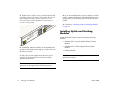
9 Continue to “Installing Uplink and Stacking Modules”
on page 16.
Installing Uplink and Stacking
Modules
OmniSwitch 6600 Family switches support the following
modules:
• OS6600-GNI-C2 Copper Gigabit Ethernet Uplink
Module
6 On OS6624, OS6648, OS660-U24, and OS6600-P24
switches verify that the power supply’s on/off switch is in
the off ( O ) position.
7 Plug a power cord (supplied) into the unit’s power
socket; next, plug the cord into an easily-accessible,
grounded power source.
• OS6600-GNI-U2 Fiber Gigabit Ethernet Uplink
Module
• Stacking Module
Note. This section does not apply to OS6602-24 and
OS6602-48 switches.
Note. Do not turn on the power supply at this time. You
will power on all supplies later in the setup process.
16
Setting Up the Hardware
March 2005
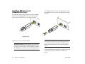
If uplink modules and/or stacking kits were specified with
your order, install them now by following the steps below:
Important. Stacking modules can only be installed in the
far-right module slot. This slot is labeled EXPANSION/
STACKING and contains port positions 27 and 28
(OS6624 and OS6600-U24) or 51 and 52 (OS6648).
screws have been removed, carefully pry the blank cover
panel out and away from the chassis. Set the cover panel
and attachment screws aside.
2 Holding the uplink or stacking module by the front
panel, carefully slide the circuit board into the card guide
located in the chassis slot.
Do not attempt to install stacking modules at the
EXPANSION slot at port positions 25 and 26 (OS6624
and OS6600-U24) or 49 and 50 (OS6648).
G
OS6600-GNI-U2 and OS6600-GNI-C2 uplink modules
can be installed in either slot location. However, if you
install a Gigabit Ethernet uplink module in the
EXPANSION/STACKING slot, the switch must be used
as a stand-alone unit.
KIN
AC
ST 5 2
N/
IO
S
AN
XP
E
51
Port numbers are clearly marked on the OmniSwitch 6600
Family chassis front panels.
CT
K/A
LIN
CT
K/A
LIN
Anti-Static Warning. Before handling any components,
free yourself of static by wearing a grounding strap, or by
grounding yourself properly. Static discharge can damage
the switch and the uplink or stacking module.
Note. The module should slide in easily. Do not force the
module into the slot. If any resistance is encountered,
ensure that the module is aligned properly in the card
guide and try again.
1 If there is a blank cover panel installed over the uplink
or stacking module slot position, uninstall it by removing
the two Phillips attachment screws. After the attachment
March 2005
Setting Up the Hardware
17
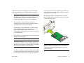
3 Slide the module back until the backplane connector is
inserted in the chassis backplane; the module’s front panel
should be flush with the front of the chassis. Do not force
the module into the slot. Otherwise you can damage the
connectors.
Installing MiniGBIC Connectors
Each OS6600-GNI-U2 uplink module supports up to two Mini
Gigabit Interface Converters (MiniGBICs). These MiniGBICs
are packaged separately and therefore are not factory-installed.
4 Once the module is firmly seated and flush with the
chassis front panel, secure the module by tightening the
two captive screws. Be sure not to overtighten the captive
screws. If you use a screwdriver, the torque used to
tighten the screws must not exceed 2.3 inch pounds.
RX
Mini Gigabit Interface Converter (MiniGBIC)
ON
SI
N
PA
G
IN
CK
TA 5 2
S
/
TX
EX
51
CT
K/A
LIN
CT
K/A
LIN
If you are using one or more OS6600-GNI-U2 modules to
uplink to the backbone or server, you must install the MiniGBIC(s) by following the steps below.
Anti-Static Warning. Before handling any components,
free yourself of static by wearing a grounding strap, or by
grounding yourself properly. Static discharge can damage
the MiniGBIC, as well as the switch and uplink module.
18
Setting Up the Hardware
March 2005
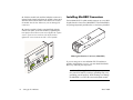
1 Holding the MiniGBIC by its sides, carefully slide it
2 Push the MiniGBIC into the slot until it is completely
into the desired MiniGBIC slot in the OS6600-GNI-U2
module, as shown.
inserted and securely seated in the OS6600-GNI-U2
module, as shown.
G
IN
K
AC
ST 5 2
N/
IO
NS
PA
EX
51
G
KIN
AC
ST 5 2
/
ON
SI
N
PA
EX
51
G
KIN
TAC
52
N/S
SIO
AN
EXP
51
50
47
49
45
N
SIO
AN
EXP
43
41
48
23
39
46
21
37
44
19
35
42
17
33
40
15
31
wi
tch
66
22
18
16
14
30
5
24
20
36
11
34
9
32
7
niS
24
38
13
29
27
25
Om
TM
28
3
12
26
1
10
8
E
SOL
CON
6
4
2
PRI
PS1
OK1
PS2
SEC
TEMP
SEL
FAN
OK2
Note. The MiniGBIC should slide in easily. Do not force
the MiniGBIC into the slot. Otherwise you can damage the
connectors. If any resistance is encountered, ensure the
MiniGBIC is aligned and oriented properly, as shown in
the diagram above.
March 2005
Setting Up the Hardware
19
Installing SFP Connectors
(OS6600-U24 Only)
1 Holding the SFP by its sides, carefully slide it into the
desired SFP slot (ports 1–24) on the OS6600-U24 module,
as shown.
The OS6600-U24 supports up to twenty-four 924) 100 Mbps
Small Form-factor Pluggable (SFPs). These SFPs are packaged separately and therefore are not factory-installed.
100 Mbps SFP
Follow the steps below to install an SFP.
Anti-Static Warning. Before handling any components,
free yourself of static by wearing a grounding strap, or by
grounding yourself properly. Static discharge can damage
the MiniGBIC, as well as the switch and uplink module.
Note. The SFP should slide in easily. Do not force the
SFP into the slot. Otherwise you can damage the connectors. If any resistance is encountered, ensure the SFP is
aligned and oriented properly, as shown in the diagram
above.
2 Push the SFP into the slot until it is completely inserted
and securely seated in the OS6600-U24 SFP slot, as
shown.
20
Setting Up the Hardware
March 2005
Blank Cover Plates
Blank cover plates are factory-installed in the chassis and are
used to cover empty uplink and stacking module slots, as well
as empty back up power supply bays.
These cover plates play an important role in chassis airflow
and temperature management. They also protect the switch’s
processor board and other sensitive internal switch components from physical damage by closing off a chassis that is not
fully populated.
Because they regulate airflow and help protect internal chassis
components, blank cover plates should remain installed over
empty module slots and power supply bays at all times.
For detailed diagrams showing chassis airflow and the effects
of missing blank cover plates on chassis airflow, refer to the
Hardware Users Guide.
March 2005
Setting Up the Hardware
21
Connections and Cabling
Once your switch is properly set up and all required hardware
components are installed, you should connect all network and
management cables required for your network applications.
Connections may include:
• Serial cable (OS6624 and OS6648) or RJ-45 (OS6600-
U24, OS6600-P24, OS6602-24, OS6602-48) to the
console port
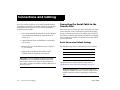
Connecting the Serial Cable to the
Console Port
The console port, located on the chassis front panel, provides a
serial connection to the switch and is required when logging
into the switch for the first time. By default, this connector (a
male DB-9 on OS6624 and OS6648 and an RJ-45 on OS6600U24, OS6600-P24, OS6602-24, OS6602-48) provides a DCE
console connection.
• Gigabit Ethernet cables to MiniGBICs, as required by
your network
• Ethernet cables to 10/100 Ethernet ports, as required
by your network
• Single mode or multimode fiber cables to SFPs
(OS6600-U24), as required by your network
Important. If you are installing switches in a stacked
configuration, do not install the stacking cables at this
time, as this will adversely affect the slot assignments.
You will be prompted to install the stacking cables later in
the setup process.
Serial Connection Default Settings
The default settings for the serial connection are as follows:
baud rate
9600
parity
none
data bits (word size)
8
stop bits
1
For information on modifying these settings, refer to
“Modifying the Serial Connection Settings” on page 38.
Stacked Configurations. To modify the default serial
settings for switches in a stack, you must configure these
settings when each switch is operating as a stand-alone
unit.
22
Connections and Cabling
March 2005
The Next Step
If you are setting up a stand-alone OmniSwitch 6600 Family
switch (i.e., a switch that is not a part of a stacked configuration), skip to “Booting Stand-Alone Switches” on page 29.
March 2005
Connections and Cabling
23
Completing a Stacked Configuration
All switches in the stacked configuration should now be
placed in their proper location (e.g., tabletop to rack). In order
to complete the stacked configuration process, you must
complete the following steps:
• By default, the primary—or management—role will be
given to the switch with the lowest chassis MAC
address. All other switches in the stack will be in nonoperational status until slot numbers are assigned by
the user and the stack is manually rebooted.
1 Individually assign slot numbers to all switches
2 Attach all required stacking cables
3 Boot the newly-configured stack
For OmniSwitch 6600 Family switches, the term “slot” refers
to the priority status of the switch within the stacked configuration. Slot numbers may range from 1 to 8.
Slot Assignment Guidelines
Before assigning slot numbers to switches in a stacked configuration, note the following guidelines.
• Slot numbers do not need to be sequential. However,
each switch in a stack must have a unique slot number.
If duplicate slot numbers are encountered, an error will
occur and the stack will be disabled.
• After manually assigning the slot assignments for all
switches and rebooting the stack, the primary role will
be given to the switch with the lowest slot number. The
secondary role will be given to the switch with the
next-lowest number. All additional switches with
higher numbers will be given idle status. For more
information on primary, secondary, and idle roles, refer
to the “Managing OmniSwitch 6600 Family Stacks”
chapter in the OmniSwitch 6600 Family Hardware
Users Guide.
• Changing the slot number of a chassis does not imme-
diately change its management role (i.e., primary,
secondary, or idle). You must reboot all the switches in
the stack before these changes will take effect.
Refer to the illustration on page 26 for one of many valid
slot numbering possibilities.
• The top switch in the stack does not have to be desig-
nated as slot 1.
24
Completing a Stacked Configuration
Follow the steps beginning on page 25 to assign slot numbers
for OmniSwitch 6600 Family switches.
March 2005
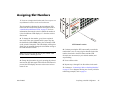
Assigning Slot Numbers
1 Power on a single switch in the stack. Do not power on
any additional switches in the stack at this time.
The slot number is displayed by the slot indicator LED
located on the left side of the chassis front panel (refer to
“OmniSwitch 6600 Status LEDs” on page 67 for more
information). Because the switch’s default slot number is
8, the slot indicator LED displays “8” when the switch is
first booted.
1
OK
2
OK
1
PS
2
PS
L
SE
EM
I T
PR
C
SE
34
9
25
iS
mn
14
30
5
4
62
h6
tc
wi
28
3
12
26
1
10
8
O
E
OL
NS
CO
TM
16
32
7
N
FA
6
4
2
1
OK
2
OK
1
PS
2
PS
P
EM
I T
PR
C
SE
L
SE
N
FA
2 To change the slot number, gently insert a pointed
item, such as the open, pointed end of a paper clip, into
the small hole (labeled SEL) below the slot number LED
on the switch’s front panel. The LED display will begin to
flash. You can manually change the slot number as long as
the LED continues to flash.
SEL Button Location
4 Continue pressing the SEL button until you reach the
Note. The LED may also advance by one number when
the SEL button is initially pressed.
number that is one increment higher than the desired slot
number, then hold in the SEL button until the LED
decreases one increment (to your desired number) and
stops flashing.
3 Change the slot number by gently pressing the pointed
5 Power off the switch.
item into the SEL hole again. Each time the SEL button is
pressed, the LED display increases or decreases in increments of one.
6 Repeat steps 1 through 5 for all switches in the stack.
7 Continue to “Connecting Cables to Stacking Modules”
on page 27. For a diagram showing one of many valid slot
numbering examples, refer to page 26.
March 2005
Completing a Stacked Configuration
25
Slot Numbering Example
31
29
36
11
27
34
9
25
Valid Slot Assignments
32
7
tch
i
iSw
24
66
O
NS
LE
P
EM
I T
PR
C
SE
2
PS
2
OK
SE
L
29
36
11
27
34
9
25
32
7
N
FA
tch
i
iSw
30
5
24
66
28
3
12
26
1
mn
10
CO
NS
OL
E
P
EM
I T
PR
C
SE
2
PS
2
OK
SE
L
34
9
N
FA
h
itc
30
5
24
66
w
niS
O
NS
28
3
10
2
PS
LE
31
29
SE
L
36
11
27
34
9
25
32
7
N
FA
h
itc
28
3
NS
OL
sequential (4, 5, 6, and 3), all switches
in the stack have a unique slot number.
• The top switch in the stack does not
have to be designated as slot 1; for this
example, the top switch has been
designated slot number 4.
• Because it has the lowest user-assigned
slot number, switch number 3 will be
given the stack’s primary management
role in this example. Switch number 4
will be given the secondary role.
Switches 5 and 6 will be given idle
status. Refer to the Hardware Users
Guide for more information.
12
26
1
10
8
O
CO
• Although the slot numbers are not
30
5
24
66
w
iS
mn
TM
33
6
P
EM
I T
PR
C
SE
35
8
4
1
PS
2
OK
12
26
1
2
1
OK
36
11
27
25
32
7
Om
TM
CO
31
29
2
1
OK
33
6
4
1
PS
35
8
O
TM
The illustration at left (showing a stacked
configuration with four switches) shows one
of many valid slot numbering possibilities.
31
4
1
PS
35
33
6
2
1
OK
12
10
8
TM
CO
28
3
26
1
n
Om
30
5
E
6
4
2
1
OK
2
OK
1
PS
2
PS
P
EM
I T
PR
C
SE
SE
L
N
FA
Stack of Four Switches with Unique Slot Numbers
26
Completing a Stacked Configuration
March 2005
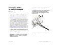
Connecting Cables
to Stacking Modules
Guidelines
• Port numbers are clearly marked on the chassis front
panel.
1 Starting from the top of the stack, attach one end of a
30 cm stacking cable to a High Speed Serial Data
Connector (HSSDC) located on the switch’s stacking
module, as shown.
• If you have not already individually assigned slot
numbers and powered off each switch, do not connect
stacking cables to the stacking modules. Instead, refer to
“Assigning Slot Numbers” on page 25 and follow the
instructions for assigning slot numbers to each switch.
• Before attempting to connect OmniSwitch 6600 Family
switches in a stacked configuration, be sure that stacking
modules are installed in the EXPANSION/STACKING
slots of all switches. The stacking module provides two
dedicated High Speed Serial Data Connectors (HSSDCs) at
ports 27 and 28 (OS6624, OS6600-U24, OS6600-P24,
OS6602-24) or 51 and 52 (OS6648 and OS6602-48). For
detailed information on installing stacking modules, refer
to “Installing Uplink and Stacking Modules” on page 16.
G
KIN
AC
ST 5 2
/
ON
SI
N
PA
EX
51
CT
K/A
LIN
CT
K/A
LIN
• Stacking modules can only be installed in the far-right
module slot. This slot is labeled EXPANSION/STACKING and contains port positions 27 and 28 (OS6624 and
6600-U24) or 51 and 52 (OS6648).
Attaching the Stacking Cable to a Stacking Module
• Do not attempt to install the stacking module at the
EXPANSION slot at port positions 25 and 26 (OS6624,
OS6600-U24, OS6600-P24, OS6602-24) or 49 and 50
(OS6648 and OS6602-48).
March 2005
Completing a Stacked Configuration
27
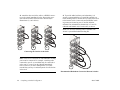
2 Attach the other end of the cable to a HSSDC connec-
3 To provide added resiliency and redundancy, it is
tor on the switch immediately below. Repeat this procedure until all switches in the stack are connected (see
illustrations a, b, and c below).
strongly recommended that you install the optional onemeter stacking cable to connect the top switch in the stack
to the bottom switch. Connect the unused HSSDC stacking connectors located at ports 27 and 28 (OS6624,
OS6600-U24, OS6600-P24, OS6602-24) or 51 and 52
(OS6648 and OS6602-28) of each switch, as shown.
NG
ON
EX
PA
/S
TA
CKI
52
ON
NSI
CT
K/A
LIN
51
EX
PA
/S
/S
TA
CKI
52
ON
NSI
CT
K/A
LIN
51
EX
PA
/S
PA
/S
N
CKI
TA 5 2
TA
ON
CT
K/A
LIN
CKI
52
ON
NSI
CT
K/A
LIN
EX
PA
/S
G
EX
PA
/S
N
CKI
TA 5 2
Note. The one-meter stacking cable is available with
Alcatel’s optional Redundant Stacking Kit.
G
NSI
CT
K/A
LIN
51
CT
K/A
LIN
N
CKI
TA 5 2
G
ON
NSI
CT
K/A
LIN
51
EX
PA
/S
N
CKI
TA 5 2
G
NSI
CT
K/A
LIN
51
CT
K/A
LIN
CT
K/A
LIN
N
CKI
TA 5 2
CT
K/A
LIN
G
CT
K/A
LIN
51
/S
NSI
51
NSI
NG
ON
PA
EX
CT
K/A
LIN
51
CT
K/A
LIN
EX
ON
CT
K/A
LIN
NG
ON
PA
G
CT
K/A
LIN
CT
K/A
LIN
EX
N
CKI
TA 5 2
NSI
51
CT
K/A
LIN
G
NG
ON
EX
PA
/S
TA
CKI
52
ON
NSI
CT
K/A
LIN
51
CT
K/A
LIN
a
EX
PA
/S
CKI
TA 5 2
NG
ON
NSI
CT
K/A
LIN
51
CT
K/A
LIN
b
EX
PA
/S
CKI
TA 5 2
IN
CK
TA 5 2
NG
IO
NS
PA
NSI
S
N/
EX
CT
K/A
LIN
51
CT
K/A
LIN
51
CT
K/A
LIN
CT
K/A
LIN
c
G
IN
CK
TA 5 2
IO
NS
PA
S
N/
EX
CT
K/A
LIN
51
CT
K/A
LIN
Connecting the Switches in the Stack
G
IN
CK
TA 5 2
IO
NS
PA
S
N/
EX
CT
K/A
LIN
51
CT
K/A
LIN
Note. There are no restrictions on which HSSDC stacking
ports must be connected. For example, a stacking cable
connected to port 51 on an OS6648 may be connected to
either port 51 or port 52 on the OS6648 immediately
below. However, for easier management, it is recommended that you keep a consistent pattern for all switches
in the stack.
28
Completing a Stacked Configuration
G
IN
CK
TA 5 2
IO
NS
PA
S
N/
EX
51
CT
K/A
LIN
CT
K/A
LIN
d
Recommended Redundant Connection Between Switches
March 2005
4 Now that all switches in the stack are connected,
3 After you have booted the stack and powered on all
continue to “Booting the Stack” on page 29.
back up power supplies (if applicable), continue to
“Verifying LED Status” on page 30.
Booting the Stack
In order for the switches in the stack to operate using their
newly-assigned slot numbers, all switches in the stack must be
manually booted. To manually boot the stack, follow the steps
below.
1 Power on all switches by moving the on/off switch for
each switch to the on ( | ) position.
Booting Stand-Alone
Switches
1 To boot a single, stand-alone switch, simply move the
on/off switch for each switch to the on ( | ) position. This
switch is located on the rear panel of the switch, next to
the power cord socket.
Important. Be sure to power on all switches in the stack
in rapid succession. If you do not power up all switches
within approximately three seconds, switches may take
unintended stack management roles.
Note. Because the switch’s default slot number is 8, the
slot indicator LED displays “8” when the switch is first
booted.
After the stack is completely booted, all switches in the
stack will operate with the user-assigned slot numbers.
2 If the stand-alone switch has a back up power supply
installed, you may power on this unit as well. Move the
on/off switch for the back up power supply to the on ( | )
position.
Automatic Software Synchronization. In order to ensure
effective redundancy within a stacked configuration, the
primary switch will automatically distribute its system and
configuration software to all switches in the stack as the
virtual chassis boots.
3 After you have booted the stand-alone switch and
powered on the back up power supply (if applicable),
continue to “Verifying LED Status” on page 30. This
section provides information on LED states and switch
status both during and after the boot process.
2 If back up power supplies are installed in one or more
switches in the stack, power on all back up power supplies
at this time.
March 2005
Completing a Stacked Configuration
29
Verifying LED Status
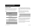
Component LEDs
The boot process takes a few moments to complete. During
this process, the LEDs on the switch’s front panel may flash
and change color, indicating different stages of the boot.
Following a successful boot, the LEDs should display as
follows:
30
OK1
Solid Green
OK2
Blinking Green
PS1
Solid Green
PS2
Solid Green (if back up power supply is
installed). Amber if no back up power supply is installed or if a back up power supply
error has occurred.
PRI
Solid Green (if the switch is either a standalone switch or the primary switch in a
stack; otherwise, if the switch status is secondary or idle, this LED is off)
SEC
Solid Green (if the switch is the secondary
switch in a stack; otherwise, this LED is
off)
TEMP
Solid Green
FAN
Solid Green
Verifying LED Status
If the LEDs do not display as indicated, make sure the boot
process is complete. Again, the boot process may take several
moments to complete. If the LEDs do not display as indicated
following a complete boot sequence, contact Alcatel Customer
Support.
Verifying Primary and Secondary Status
Primary, Secondary and Idle switch status is monitored
through the PRI and SEC LEDs.
Note. The PRI and SEC LEDs on the switch’s front panel
are the most accurate and reliable method for determining
the current role of a switch within a stacked configuration.
PRI LED
Now that the stack has been completely configured and rebooted, the primary—or management—role should be assigned to
the switch with the lowest assigned slot number. In other
words, if you assigned a switch in the stack as slot 1, this
switch should have the primary role.
To verify this, check the PRI LED on the front panel of the
switch with the lowest assigned slot number. The PRI LED
should be illuminated solid green.
March 2005
SEC LED
The secondary role is given to the switch with the next-lowest
number.
To verify this, check the SEC LED on the front panel of the
switch with the next-lowest assigned slot number. The SEC
LED should be illuminated solid green.
Idle Status
All additional switches with higher numbers will be given idle
status. The PRI and SEC LEDs for these switches will be off.
For additional information on primary, secondary, and idle
roles within the stack, refer to the Hardware Users Guide.
Additional LED Descriptions. For complete descriptions of OmniSwitch 6600 Family LED states, see page
67.
March 2005
Verifying LED Status
31
Your First Login Session
Once the switch or stack has successfully booted and you have
accessed your computer’s terminal emulation software via the
console port, you are ready to log in to the switch’s Command
Line Interface (CLI) and configure basic information.
Note. You must be connected to the switch via the console
port before initiating your first login session.
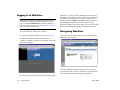
Logging In to the Switch
Important. If you are using OmniSwitch 6600 Family
switches in a stacked configuration, you must be
connected to the console port of the stack’s primary
switch. For detailed information on primary switch status,
refer to the Hardware Users Guide.
When you first log in to the switch, you will be prompted for a
login (i.e., user) name and password. During this first login
session, only one user name option and one password option is
available:
• Login (i.e., user name)—admin
In order to complete the setup process for the switch or stack,
you should complete the following steps during your first
login session:
• Password—switch
To log in to the switch, enter admin at the login prompt:
• Log in to the switch
login: admin
• Unlock session types
• Change the login password
• Set the date and time
Next, enter the factory default password, switch, at the
password prompt:
password: switch
• Set optional system information
• Save your changes
32
Your First Login Session
March 2005
The default welcome banner, which includes information such
as the current software version and system date, displays—
followed by the CLI command prompt:
Welcome to the Alcatel OmniSwitch 6000
Software Version 5.1.5, June 30, 2004.
Copyright(c), 1994-2004 Alcatel Internetworking, Inc.
All Rights reserved.
OmniSwitch(TM) is a trademark of Alcatel Internetworking, Inc. registered in the United States Patent and
Trademark Office.
Setting user profile...
->
More Information on User Accounts. A user account
includes a login name, password, and user privileges.
Privileges determine whether the user has read or write
access to the switch and which commands the user is
authorized to execute.
For detailed information on setting up and modifying user
accounts and user privileges, refer to the “Managing
Switch User Accounts” chapter of your OmniSwitch 6600
Family Switch Management Guide.
March 2005
Assigning an IP Address to the
Switch or Stack
Assigning an IP address to your OmniSwitch 6600 Family
switch or stack is an important step in the setup process.
Remote sessions such as Telnet, FTP, and WebView require
an IP address. The IP address for these session types serves as
a destination point for the remote session. Therefore, before
the switch can support any remote login sessions, a valid IP
address must be configured.
To assign an IP address to a switch, simply assign an IP
address to the switch’s default VLAN 1 by entering the
ip interface command at the CLI prompt. Be sure that the
command begins with the command syntax
ip interface
exactly as shown, followed by the the interface name, address,
the IP address, vlan, and the VLAN number. For example:
-> ip interface vlan-1 address 172.22.120.1
vlan 1
Your First Login Session
33
Assigning IP Addresses to Switches in a
Stacked Configuration
It is important that all switches in a stacked configuration have
the same assigned IP address. This way, if a failover should
occur (i.e., another switch in the stack assumes the primary
management role), users can still log in to the stack via remote
login sessions such as Telnet, FTP, and WebView.
The IP assigned to the stack’s primary switch is dynamically
assigned to all other switches in the stack whenever either of
the following actions occurs:
• The entire stack is rebooted
• The copy flash-synchro command is entered at the CLI
prompt on the stack’s primary switch
You are not required to manually assign the IP address to each
switch in the stack.
Avoiding Duplicate IP Addresses in the Network.
If any stacking cable (other than the optional redundant
stacking cable) is disconnected while the stack is in operation, a duplicate IP addresses will exist on the network.
Therefore, if a switch is to be pulled from a stack, it is
recommended that the switch is given a unique IP address
via the (ip interface command) before being
disconnected.
34
Your First Login Session
Unlocking Session Types
Security is a key feature on OmniSwitch 6600 Family
switches. As a result, when you access the switch for the first
time, you must use a direct console port connection. All other
session types (Telnet, FTP, WebView, SNMP, etc.) are
“locked out” until they are manually unlocked by the user.
The CLI command used to unlock session types is
aaa authentication.
Note. When you unlock session types, you are granting
switch access to non-local sessions (e.g., Telnet). As a
result, users who know the correct user login and password will have remote access to the switch. For more
information on switch security, refer to the “Managing
Switch User Accounts” chapter of your OmniSwitch 6600
Family Switch Management Guide.
Unlocking All Session Types
To unlock all session types, enter the following command
syntax at the CLI prompt:
-> aaa authentication default local
March 2005
Unlocking Specified Session Types
Changing the Login Password
You can also unlock session types on a one-by-one basis. For
example, to unlock Telnet sessions only, enter the following
command:
Change the login password for admin user sessions by following the steps below:
1 Be sure that you have logged into the switch as user
-> aaa authentication telnet local
To unlock WebView (HTTP) sessions only, enter the following command:
type admin (see “Logging In to the Switch” on page 32).
2 Enter the keyword password and press Enter.
3 Enter your new password at the prompt (refer to the
-> aaa authentication http local
You cannot specify more than one session type in a single
command line. However, you can still unlock multiple session
types by using the aaa authentication command in succession. For example:
-> aaa authentication http local
-> aaa authentication telnet local
-> aaa authentication ftp local
note below).
Note. Typically, the password should be a string of nonrepeating characters. The switch’s authentication software
uses the first occurrence of the character Family to
uniquely identify the password. For example, the password engrengr is the same as engr. A better password
might be engr2735.
How many sessions are allowed?
4 You will be prompted to re-enter the password. Enter
Once a session type has been unlocked, the following number
of sessions is allowed for each type:
the password a second time.
Telnet sessions allowed
4 concurrent sessions
FTP sessions allowed
4 concurrent sessions
HTTP (Web browser) sessions allowed
4 concurrent sessions
Total sessions (Telnet, FTP,
HTTP, console)
13 concurrent sessions
SNMP sessions allowed
50 concurrent sessions
March 2005
Note. Be sure to remember or securely record all new
passwords; overriding configured passwords on
OmniSwitch 6600 Family switches is restricted.
New password settings are automatically saved in real time to
the local user database; the user is not required to enter an
additional command in order to save the password information. Also note that new password information is retained
following a reboot.
Your First Login Session
35
All subsequent login sessions—including those through the
console port—will require the new password in order to access
the switch.
User Accounts. The switch allows a maximum of 50 user
accounts in the local user database. For information on
creating additional user types and assigning individual
passwords, refer to the “Managing Switch User Accounts”
chapter of your Switch Management Guide.
Setting the Date and Time
Set the current time for the switch by entering system time,
followed by the current time in hh:mm:ss. For example:
-> system time 18:35:00
The switch uses a 24-hour clock; the time value shown in the
above example would set the time to 6:35 PM.
To set the current date for the switch, enter system date,
followed by the current date in mm/dd/yyyy. For example:
Setting the System Time Zone
-> system date 06/27/2002
The switch’s default time zone is UTC (also referred to as
Greenwich Mean Time).
If you require a time zone that is specific to your region—or if
you need to enable Daylight Savings Time (DST) on the
switch—you can configure these settings via the system timezone and system daylight savings time commands. For example, to set the system clock to run on Pacific standard time,
enter the following command.
-> system timezone pst
To enable Daylight Savings time, enter the following
command.
-> system daylight savings time enable
Many other time zone variables are supported. For detailed
information on configuring a time zone for the switch, refer to
your OmniSwitch 6600 Family Switch Management Guide.
36
Your First Login Session
March 2005
Setting Optional System
Information
This section provides information on configuring optional
system parameters, including:
• the switch’s administrative contact
• a system name
Specifying a System Name
The system name is a simple, user-defined text description for
the switch.
To specify a system name, enter system name, followed by a
text description of up to 19 characters.
Note. You cannot include spaces between words when
entering a system name.
• the switch’s physical location
For example:
Specifying an Administrative Contact
An administrative contact is the person or department in
charge of the switch. If a contact is specified, users can easily
find the appropriate network administrator if they have questions or comments about the switch.
To specify an administrative contact, enter system contact,
followed by a text string of up to 254 characters. If you
include spaces between words in the text string, be sure to
enclose the string in quotes ("").
For example:
-> system contact "JSmith [email protected]"
-> system name EngSwitch3
Specifying the Switch’s Location
It is recommended that you use a physical labeling system for
locating and identifying your switch(es). Examples include
placing a sticker or placard with a unique identifier (e.g., the
switch’s default IP address) on each chassis.
However, if no labeling system has been implemented or if
you need to determine a switch’s location from a remote site,
entering a system location can be very useful.
To specify a system location, enter system location, followed
by a text description of up to 254 characters. If you include
spaces between words in the text string, be sure to enclose the
string in quotes ("").
For example:
-> system location "NMS Lab--NE Rack"
March 2005
Your First Login Session
37
Viewing Your Changes
To view your current changes, enter show system at the CLI
prompt.
Saving Your Changes
Modifying the Serial Connection
Settings
The switch’s serial connection defaults are listed on page 22.
If you wish to modify the default serial connection settings
(i.e., baud rate, parity, data bits, and stop bits), refer to the
following steps.
Once you have configured this basic switch information, save
your changes by entering write memory at the CLI command
prompt.
Note. You must be connected to the switch via the console
port before attempting to change serial connection
settings. Otherwise, an error message will display.
When the write memory command is entered, changes are
automatically saved to the main configuration file (boot.cfg)
and placed in the /flash/working directory. For more information on the boot.cfg file, refer to page 48.
For switches in a stacked configuration, all changes must
be configured before the switches are cabled together. In
other words, you must configure these settings when each
switch is operating as a stand-alone unit.
Note. If the switch reboots following a write memory
command entry, the switch will run from the
/flash/certified directory. As a result, subsequent configuration changes cannot be saved using the write memory
command until the switch is once again running from the
/flash/working directory. See page 51 for important information on these directories.
1 Enter modify boot parameters at the CLI prompt. The
boot prompt displays:
Boot >
2 To change the baud rate, enter boot serialbaudrate,
followed by the desired baud rate value. Options include
1200, 2400, 4800, 9600 (default), 19200, 38400, 57600,
76800, and 115200. For example:
Boot > boot serialbaudrate 19200
Note. Setting the console port to speeds above 9600 baud
can cause problems with Zmodem uploads.
38
Your First Login Session
March 2005
3 To change the parity value, enter boot serialparity,
followed by the desired parity value. Options include none
(default), even, and odd. For example:
7 You can save your changes to the boot.params file by
entering commit file at the boot prompt:
Boot > commit file
Boot > boot serialparity even
4 To change the data bits (i.e., word size) value, enter
When the commit file command is used, changes will not
be enabled until after the next switch reboot.
boot serialwordsize, followed by the number of data bits.
Options include 7 and 8 (default). For example:
8 You can also save your changes in real time to the
switch’s running memory by entering commit system at
the boot prompt:
Boot > boot serialwordsize 7
Boot > commit system
5 To change the stop bits value, enter boot
serialstopbits, followed by the number of stop bits.
Options include 1 (default) and 2. For example:
Boot > boot serialstopbits 2
Caution. There are two important things to consider when
using the commit system command to save serial connection changes:
6 Verify your current changes by entering show at the
• Output to the terminal may become illegible due to
boot prompt:
Boot > show
Edit buffer contents:
Serial (console) baud
Serial (console) parity
Serial (console) stopbits
Serial (console) wordsize
incompatible serial connection settings between the
switch and the terminal emulation software.
:
:
:
:
19200
even
2
7
• If you use the commit system command only, changes
will not be saved to the switch’s boot.params file and
will be lost if the switch is rebooted. To save changes
to the boot.params file, refer to step 7.
(additional table output not shown)
9 Return to the CLI prompt by entering exit at the boot
prompt.
March 2005
Your First Login Session
39
This completes the initial setup process. Your OmniSwitch
OmniSwitch 6600 Family switch is now ready for additional
configuration and network operation. Refer to the following
sections for more information on using your switch, as well as
additional built-in features.
40
Your First Login Session
March 2005
CLI Basics
The Command Line Interface (CLI) allows you to configure
and monitor your switch by entering single-line commands.
The CLI can be accessed through terminal or Telnet sessions.
Note. Configuring the switch using the CLI is also
referred to as “online configuration.”
The following section provides basic information on CLI
assistance features. For detailed information on the CLI,
including syntax conventions, usage rules, command documentation, and a quick reference card, refer to the OmniSwitch
CLI Reference Guide and the “Using the CLI” chapter in the
OmniSwitch 6600 Family Switch Management Guide.
CLI Assistance Features
Note. The software supports vt100 terminal emulation;
CLI assistance features may be limited if your terminal
emulation software is using a setting other than vt100.
Syntax Checking
If you make a mistake while entering command syntax, the
CLI provides clues about how to correct the error. Whenever a
command error is entered, two indicators are displayed:
• An Error message describing the type of error.
• A carat (^) character indicating where the error
occurred.
For example, the syntax
-> show vlan router port mac status
The CLI provides built-in features that assist you while entering commands. These features include:
• Syntax checking
• Command line help
• Partial keyword completion
• Deleting and inserting characters
• Previous command recall
• Prefix recognition
• Prefix prompt
• Command history
March 2005
results in the following error:
-> show vlan router port mac status
^
ERROR: Invalid entry: "port"
Because port is not valid syntax for the command, the error
message shows it as an invalid entry and the carat indicates
where the problem has occurred. For this example, the valid
command syntax is
-> show vlan router mac status
CLI Basics
41
Command Line (?) Help
Partial Keyword Completion
The CLI provides additional help in the form of the question
mark (?) character. The ? character provides information that
helps you build your command syntax. For example, if you
enter
The CLI has a partial keyword recognition feature. Instead of
typing an entire keyword, you can type only the minimum
number of characters needed to uniquely identify the keyword,
then press the Tab key. The CLI will complete the keyword
and place the cursor at the end of the command line.
-> show vlan router
at the command line and are unsure of the next keyword, you
can enter the ? character for additional options (be sure to
include a space between the last keyword and the ? character):
-> show vlan router ?
^
MAC IP
(Vlan Manager Command Set)
The carat character (^) indicates the point where you invoked
the command line help. Possible keyword options, along with
the corresponding command set, are displayed. Here, you can
continue building the command by entering either mac or ip.
Some command completion options may indicate user-defined
information. For example: <string>, <slot/port>,
<hh:mm:ss>, etc. The option <cr> indicates that the
command can be completed by pressing Enter.
If you do not enter enough characters to uniquely identify the
keyword, pressing the Tab key will have no effect.
If you enter characters that do not belong to an applicable
keyword, pressing the Tab key will remove the characters and
place the cursor back to its previous position.
Deleting Characters
You can delete CLI command characters by using the Backspace key or the Delete key. The Backspace key deletes each
character in the line, one at a time, from right to left.
To change incorrect syntax with the Delete key, use the Left
Arrow key to move the cursor to the left of the character to be
deleted, then use the Delete key to remove characters to the
right of the cursor.
Note. The ? character can be entered at any time. In addition, you can type the ? character alone at the CLI prompt
to display root keywords for all command sets.
42
CLI Basics
March 2005
Inserting Characters
Prefix Recognition
To insert a character between characters that are already typed,
use the Left and Right Arrow keys to place the cursor into
position, then type the new character. Once the syntax is
correct, execute the command by pressing Enter. In the
following example, the user enters the wrong syntax to execute
a command. The result is an error message.
Prefix recognition is a CLI feature that reduces redundant
command line entry by storing commonly-used prefix information for certain commands. The CLI assumes this stored
prefix information when the next command is entered. For
example, if you enter
-> vlan 32
-> show micrcode
^
ERROR: Invalid entry: "micrcode"
To correct the syntax without retyping the entire command
line, use the !! command to recall the previous syntax. Then,
use the Left Arrow key to position the cursor between the “r”
and the “c” characters. To insert the missing character for this
example, type “o” as shown:
-> !!
-> show microcode
Previous Command Recall
at the command line, the CLI will store the vlan 32 prefix
information.
The following command families support prefix recognition:
• AAA
• Interface
• Link Aggregation
• Quality of Service (QoS)
• Spanning Tree
To recall the last command executed by the switch, press the
Up Arrow key at the prompt and the previous command will
display on your screen. You can execute the command again
by pressing Enter, or you can edit it first by deleting or inserting characters.
March 2005
• VLAN Management
CLI Basics
43
Prefix Prompt
You can set the CLI to display the current command prefix as
the command prompt by entering the following command:
-> prompt prefix
After entering this command, your command prompt will
include current stored prefix information until a new prompt is
specified. For example, the following is a prompt for a user
who has begun configuring VLAN 32:
-> vlan 32
To set the prompt back to the default arrow ( -> ), enter the
following syntax, exactly as shown, at the prefix prompt:
Note that the most recent commands are displayed lower in the
list. For this reason, the show history command will always be
listed last.
You can recall commands from the history list by entering an
exclamation point ( ! ). For example:
-> !4
-> show temperature
The CLI prints the fourth command from the history list (in
this case, show temperature) at the CLI prompt.
You can also recall the last command in the history list by
entering two exclamation points ( !! ). For example:
prompt string ->
Command History
You can view a list of up to 30 of the most recently executed
commands via the show history command. For example:
-> show history
1 aaa authentication default local
2 password
3 system timezone pst
4 system daylight savings time enable
5 system time 14:58:00
6 system date 11/06/2002
7 system contact "JSmith [email protected]"
8 system name EngSwitch3
9 system location "NMS Lab--NE Rack"
10 show system
11 modify boot parameters
12 show history
44
CLI Basics
-> !!
-> show history
To specify the number of commands displayed in the history
list (1 - 30), use the history size command. For example:
-> history size 10
To view the current history list settings, use the show history
parameters command. For example:
-> show history parameters
History size: 30
CurrentSize: 10
Index Range: 1-10
March 2005
Command Logging
OmniSwitch 6600 Family switches provide command logging.
This feature allows users to record up to 100 of the most recent
commands entered via Telnet and console sessions. In addition to a list of commands entered, the results of each
command entry are recorded. Results include information such
as whether a command was executed successfully, or whether
a syntax or configuration error occurred.
Note. The command history feature differs from the
command logging feature in that command history buffers up to 30 of the most recent commands. The command
information is not written to a separate log file. Also, the
command history feature includes only general keyword
syntax (i.e., it does not record full syntax, date and time,
session IP address, and entry results). For more information on command history, refer to page 44.
When command logging is enabled via the command-log
enable syntax, a file called command.log is automatically
created in the switch’s /flash directory. Once enabled, configuration commands entered on the command line will be
recorded to this file until command logging is disabled.
The command.log file has a 66402 byte capacity. This capacity allows up to 100 of the most recent commands to be
recorded. Because all CLI command logging information is
archived to the command.log file, command history information will be lost if the file is deleted.
Note. The command.log file cannot be deleted while the
command logging feature is enabled. Before attempting to
remove the file, be sure to disable command logging.
For detailed information on command logging, refer to the
OmniSwitch 6600 Family Switch Management Guide.
Refer to the sections below for more information on configuring and using CLI command logging. For detailed information
related to command logging commands, refer to the
OmniSwitch CLI Reference Guide.
Enabling Command Logging
By default, command logging is disabled. To enable command
logging on the switch, enter the following command:
-> command-log enable
March 2005
CLI Basics
45
Common CLI Commands
The following table lists some basic CLI commands that will
help you get acquainted with the CLI interface. Enter each
command exactly as shown. For complete descriptions of
these commands, refer to your OmniSwitch CLI Reference
Guide.
write memory
Saves current configuration
changes to the /flash/working
directory’s boot.cfg file. For
more information, refer to
page 48.
show running-directory Displays the current running
directory. For more information, refer to page 52.
46
show ni
Displays basic hardware and
status information for a standalone switch, or for all
switches installed in a stacked
configuration.
show cmm
Displays basic hardware and
status information for a standalone switch, or for the primary
or secondary switches installed
in a stacked configuration.
show system
Displays basic information
about the switch.
show stack topology
Displays stack-specific
information for switches in a
stacked configuration (e.g., the
current management roles for
all switches in the stack).
vlan
Creates a new VLAN.
show vlan
Displays a list of VLANs
configured on the switch.
show microcode
ip interface
Configures an IP interface to
enable IP routing on a VLAN.
For more information, refer to
page 33.
Displays the version of
software currently installed on
the switch.
session timeout
show chassis
Displays basic configuration
and status information for the
switch chassis.
Modifies the amount of time
before Telnet and console
sessions time out.
who
show module
Displays basic information for
switches in a stacked configuration.
Displays all active login
sessions (e.g., Console, Telnet,
FTP, HTTP, Secure Shell,
Secure Shell FTP)
exit
Ends the current Telnet or
console session.
CLI Basics
March 2005
Offline Configuring
Scheduling a Configuration File to be Applied
at a Later Time
You can configure OmniSwitch 6600 Family switches using
an ASCII-based text file. This is referred to as offline configuring. With offline configuring, CLI commands may be typed
into a text document (referred to as a text-based configuration
file) and then uploaded and applied to the switch.
You can apply a file to the switch immediately. You can also
schedule a file to be applied either at a specific date and time,
or after a specific amount of time has passed. Timer sessions
can greatly facilitate maintenance tasks, such as synchronized
batch updates.
An ASCII-based configuration file can be viewed or edited at
any time using a standard text editor (e.g., WordPad). The
switch also offers its own text editing buffer, so a file can be
edited in the flash file directory without having to be downloaded to a workstation.
Because they are portable, stand-alone documents, configuration files allow users to easily clone switch configurations.
Moreover, the ability to store a broad range of network information in a single text file facilitates troubleshooting, testing,
and overall network readability.
Syntax Checking
Offline configuration includes a syntax check feature. This
function will report syntax errors or typos that might cause a
command to be rejected by the switch when a configuration
file is applied.
March 2005
Generating Snapshots of the
Current Configuration
A generated snapshot captures the switch’s current configuration settings in a single text file. Captured configuration
settings can then be viewed or edited offline at any time. Troubleshooting is greatly facilitated, as aggregate network information can be read at a glance.
Snapshot files can be used as configuration files for a single
switch or for multiple switches. This allows easy cloning of
switch configurations for networks requiring multiple, similarly-configured switches. Simply place the snapshot file in the
appropriate directory of the switch(es) you want to configure
and use the CLI to apply the file.
For detailed information on offline configuring and the
features described above, refer to the OmniSwitch 6600 Family
Switch Management Guide.
CLI Basics
47
Files and Directories
Boot and Image Files
Although the flash memory on OmniSwitch 6600 Family
switches can contain many file types (e.g., log and snapshot
files), there are four specific file types that provide key switch
and network functions. These files include the boot.cfg file,
boot.params file, boot.slot.cfg file, and image (.img) files.
boot.params File
The boot.params file provides IP address, gateway, and mask
information for the switch. This information is required for
Ethernet connections to the switch.
This file also contains default console port parameters (baud
rate, etc.) and can be modified via the modify boot
parameters CLI command.
In order to be read by the switch, the boot.params file must be
placed in the /flash directory. If the file is deleted for any
reason, a new boot.params file will be automatically generated on the next system boot. However, all user-configured
information, such as IP address, gateway, and mask information, will be lost. Therefore, it is recommended that you keep a
backup copy of this file at all times.
48
Files and Directories
boot.cfg File
The boot.cfg file stores your network configuration parameters. When you first boot the switch, no boot.cfg file is
present. This file is automatically generated when you first
issue a write memory command to save your configuration
changes. The file is then automatically placed in the
/flash/working directory.
Important. Your switch must be running from the
/flash/working directory in order to save changes to the
boot.cfg file. Refer to “Working and Certified Directories” on page 51 for more information.
Once the configuration parameters stored in the boot.cfg file
are considered tested and reliable, the file can be copied to the
/flash/certified directory and become part of the “last known
good” software for the switch.
If all copies of this file are deleted and a system boot occurs,
your network configuration will be lost. Therefore, it is recommended that you keep a backup copy of this file at all times.
March 2005
boot.slot.cfg File
The boot.slot.cfg file contains the slot assignment for each
switch installed in a stacked configuration.
The slot assignment number is automatically written to the
boot.slot.cfg whenever a slot number is manually assigned
and the switch is rebooted. The following is a sample
boot.slot.cfg slot entry:
boot slot 3
No software configuration is required. For detailed information on manually assigning slot numbers, refer to page 25.
Image Files
Image files (those files with .img extensions) contain executable code that provides support for the system, Ethernet ports,
and network functions. In other words, they serve as essential
drivers for switch and network operations.
Although these files may be backed up to the root flash directory or any user-defined subdirectory, they must be present in
the /flash/working and /flash/certified directories for the
switch to operate and pass traffic.
If you delete all copies of an image file, you will be required to
contact Alcatel Customer Support for replacements. Therefore, it is recommended that you keep backup copies on your
computer’s hard drive or a locally-accessible server.
March 2005
For a complete list of OmniSwitch 6600 Family image files,
along with their functions, refer to the following table.
Hos.img
Contains the OmniSwitch 6600 Family operating system software.
Hbase.img
Contains base code for the switch.
Hrelease.img
Contains release number information
for the system software package.
Hl2eth.img
Provides support for Layer 2 switching functions.
Hrout.img
Provides support for Layer 3 routing
functions.
Hqos.img
Provides Quality of Service (QoS)
functionality.
Heni.img
Provides support for 10/100, Fast
Ethernet, and Gigabit Ethernet.
Hdiag.img
Provides enhanced hardware diagnostics for the switch.
Hadvrout.img
Alcatel’s Advanced Routing software package. Optional.
Hsecu.img
Provides enhanced security features
for the switch, such as Authenticated
VLANs (AVLANs).
Hweb.img
Provides support for the WebView
software application.
Hwebl2eth.img
Provides WebView configuration of
Layer 2 features.
Hwebrout.img
Provides WebView configuration of
basic routing features.
Files and Directories
49
Hwebqos.img
Provides WebView configuration of
Quality of Service (QoS) features.
Hwebadvrout.img Enables WebView configuration of
Alcatel’s Advanced Routing.
Optional.
Hwebsecu.img
50
Files and Directories
Provides WebView configuration of
enhanced security features for the
switch.
March 2005
Working and Certified
Directories
Alcatel’s OmniSwitch 6600 Family switches are shipped with
32 MB of flash memory. This memory is used to store files,
including boot and image files, that are used for switch operations.
The /flash directory contains two subdirectories: /working and
/certified. These directories work together to provide the
image rollback resiliency feature. Image rollback allows the
switch to return to a prior “last known good” version of software in the event of a system software problem.
Working Directory
Working Directory
Intended for: Files that are being configured
and tested. Once these files are considered
valid and reliable, they can be copied to
the Certified directory.
On reload: If the Working and Certified
directories are identical, the switch will
automatically run from software in this
directory. If the two directories are not
identical, you can instruct the switch to run
from the Working directory by issuing the
reload working command.
Saving changes: You can save configuration changes to the Working directory
via the write memory command.
configuring your switch are saved to the boot.cfg file in the
/flash/working directory.
Once the /flash/working directory’s configuration and image
files are road-tested and considered valid and reliable for your
network, they can be copied to the /flash/certified directory.
Certified Directory
Certified Directory
Intended for: Reliable, Tested configuration
and image files. The switch will roll back
to this software in the event of a system
software error.
On reload: By default, the switch will use
the software in this directory if there are
any differences between the Working and
Certified directories.
Saving changes: You cannot save configuration changes to the Certified directory.
To save your changes, be sure that your
switch is operating from the Working
directory.
The software in the /flash/certified directory should be treated
as the “gold master” for the switch. When you place configuration and image files in this directory, you are “certifying”
them as tested and reliable. If the switch is running from the
/flash/working directory and experiences a software problem,
it will “roll back” to the last known good software in the
/flash/certified directory on the next reboot.
The /flash/working directory is intended for software that is
still being configured for your network. Changes made while
March 2005
Files and Directories
51
How can I tell which directory the switch
is currently using?
When you first boot the switch, the /flash/working directory is
used; this allows you to save your initial configuration changes
to the boot.cfg file. However, subsequent boots may result in
your switch running from the /flash/certified directory. Therefore, verifying the current running directory is a key step any
time you are configuring or monitoring the switch.
View the switch’s current running directory by entering the
show running-directory command. For example:
-> show running-directory
CONFIGURATION STATUS
Running CMM
:
CMM Mode
:
Current CMM Slot
:
Running configuration
:
Certify/Restore Status
:
SYNCHRONIZATION STATUS
Flash Between CMMs
:
Running Configuration
:
Stacks Reload on Takeover:
Activation)
changes must be saved to the boot.cfg file in the
/flash/working directory. Once those changes have been roadtested, the contents of the /flash/working directory can be
copied to the /flash/certified directory via the copy working
certified command.
What happens when the switch boots?
During the boot process, the switch compares the contents of
the /flash/working and /flash/certified directories. Based on
this comparison, the switch determines which directory to use
as its running software.
Working and Certified Are Identical
PRIMARY,
DUAL CMMs,
1,
WORKING,
CERTIFY NEEDED
If the software in the /flash/working and /flash/certified
directories are completely identical, the switch considers the
software in both directories to be equally reliable. In this case,
the switch will run from the /flash/working directory.
SYNCHRONIZED,
NOT AVAILABLE,
ALL STACKs (SW
In this example, the switch is using the /flash/working directory. For more information on the show running-directory
command output, refer to the “CMM Commands” chapter in
the OmniSwitch CLI Reference Guide.
Can I save changes to the Certified directory?
Working
Directory
Working and Certified
contents are identical.
boot.cfg
Hbase.img
Hrelease.img
Etc.
Certified
Directory
boot.cfg
Hbase.img
Hrelease.img
Etc.
The switch runs
from Working.
Working
Directory
boot.cfg
Hbase.img
Hrelease.img
Etc.
Certified
Directory
boot.cfg
Hbase.img
Hrelease.img
Etc.
No. The /flash/certified directory is intended to store only
tested, reliable configuration and image files. Configuration
52
Files and Directories
March 2005
When the switch is running from the /flash/working directory
software, configuration changes can be saved via the
write memory command.
Working and Certified Are Different
If the software in the /flash/working directory differs even
slightly from the software in the /flash/certified directory, the
switch will automatically run from the /flash/certified directory.
My Working and Certified directories are different. Can
I force a reboot from the Working directory?
Yes. If its configuration and image files are known to be reliable, you can override the default and initiate a reboot from the
/flash/working directory. This is done via the reload working command. For more information, refer to your
OmniSwitch CLI Reference Guide.
Working
Directory
Working
Directory
Working and Certified
contents are different.
Working
Directory
revised_boot.cfg
Hbase.img
Hrelease.img
Etc.
boot.cfg
Hbase.img
Hrelease.img
Etc.
Certified
Directory
Certified
Directory
boot.cfg
Hbase.img
Hrelease.img
Etc.
The switch runs
from Certified.
Certified
Directory
boot.cfg
Hbase.img
Hrelease.img
Etc.
When the switch runs from the /flash/certified directory,
configuration changes cannot be saved via the write memory
command
March 2005
Working and Certified
contents are different.
revised_boot.cfg
Hbase.img
Hrelease.img
Etc.
boot.cfg
Hbase.img
Hrelease.img
Etc.
The reload working
command overrides
the default; the
switch runs from
Working.
Working
Directory
revised_boot.cfg
Hbase.img
Hrelease.img
Etc.
Certified
Directory
boot.cfg
Hbase.img
Hrelease.img
Etc.
Note. For detailed information on using directories, refer
to the “Managing CMM Directory Content” chapter in the
OmniSwitch 6600 Family Switch Management Guide.
Files and Directories
53
Loading Software
The following section describes the procedure for loading new
release software to your switch. Note that the procedure varies
slightly for stand-alone and stacked OmniSwitch 6600 Family
configurations. Follow the steps that apply to your system.
3 Using your FTP client or the CLI’s rm command,
delete all .img files from the /flash/working directory.
You can use the asterisk (*) wildcard to delete all .img
files at once. For example:
-> rm working/*.img
Note. For more detailed information on loading software
and working with directories in both stand-alone and
stacked configurations, refer to the “Managing CMM
Directory Content” chapter in the OmniSwitch 6600
Family Switch Management Guide.
Stand-Alone Configurations
1 Verify that all required image files from the new soft-
Important. Do not delete the boot.cfg file. Otherwise,
any configuration changes you have saved will be lost.
Also, do not delete files from the /flash/certified directory.
4 Using your FTP client, upload all required .img files
from the new software release to the /flash/working directory.
ware release are located on your computer’s hard drive or
a locally-accessible server.
Flash/
2 Establish an FTP session to the switch, then access the
Working Directory
/flash/working directory.
FTP
Note. Before attempting to establish an FTP session, be
sure that you have first unlocked the FTP session type via
the aaa authentication command. Otherwise, an FTP
login error will occur. See “Unlocking Session Types” on
page 34 for more information.
54
Loading Software
boot.cfg
Hbase.img
Hos.img
Hrlease.img
Heni.img
Additional
required files
March 2005
5 Use the install command after the software files have
been transferred to the switch via FTP. For example:
Stacked Configurations
1 Verify that the OK1 LED is solid green and the OK2
-> install /flash/working/*.img
Note. For more information on the install command, refer
to the OmniSwitch 6600 Family Switch Management
Guide or the OmniSwitch CLI Reference Guide.
LED is flashing green on both the stack’s primary and
secondary OmniSwitch 6600 Family switches.
2 Next, verify that all required image files from the new
software release are located on your computer’s hard drive
or a locally-accessible server.
3 Establish an FTP session to the primary switch in the
6 Reload the switch from the /flash/working directory.
stack, then access the /flash/working directory.
To do this, enter
-> reload working no rollback-timeout
at the CLI prompt.
Note. This reload process will take a few moments to
complete.
Following the reload, the switch will come up running from
the /flash/working directory (i.e., the new release software)
until the next system reboot. Meanwhile, the software in the
/flash/certified directory remains unchanged and available as
a last known good version if an error should occur with the
new software.
Once the release software is considered valid and reliable with
your network configuration, the contents of the
/flash/working directory can be copied to the
/flash/certified directory via the copy working certified
command.
March 2005
Note. Before attempting to establish an FTP session, be
sure that you have first unlocked the FTP session type via
the aaa authentication command. Otherwise, an FTP
login error will occur. See “Unlocking Session Types” on
page 34 for more information.
4 Using your FTP client or the CLI’s rm command,
delete all .img files from the /flash/working directory on
the stack’s primary switch. (To determine whether you are
logged into the primary switch, use the show runningdirectory command.) You can use the asterisk (*) wildcard to delete all .img files at once. For example:
-> rm working/*.img
Note. Do not delete the boot.cfg file. Otherwise, any
configuration changes you have saved will be lost. Also,
do not delete the boot.slot.cfg file or files from the
/flash/certified directory.
Loading Software
55
5 Using your FTP client, upload all required .img files
from the new software release to the primary switch’s
/flash/working directory.
6 Use the install command after the software files have
been transferred to the switch via FTP. For example:
-> install /flash/working/*.img
Note. For more information on the install command, refer
to the OmniSwitch 6600 Family Switch Management
Guide or the OmniSwitch CLI Reference Guide.
7 Reload the switch from the /flash/working directory.
To do this, enter
-> reload working no rollback-timeout
Certifying Your New Software
After the newly-loaded software is considered tested and reliable, it is important that you certify the new software by copying it to the /flash/certified directory.
It is also important that you synchronize the contents of the
/flash/working and /flash/certified directories on all switches
in the stack with the newer contents of the /flash/certified and
/flash/working directories on the primary switch.
Otherwise, your new software—along with any configuration
changes you have made—will be lost if a reboot or failover
occurs.
To certify and synchronize all new software in the stack, enter
the following command:
-> copy working certified flash-synchro
at the CLI prompt.
Note. This reload process will take a few moments to
complete.
During this reload, software from the primary switch is distributed to all switches in the stacked configuration. By synchronizing the system software, the primary switch ensures
effective redundancy throughout the stack.
56
Loading Software
March 2005
Using WebView
The switch can be configured and monitored using WebView,
Alcatel’s Web-based device management tool. WebView software is pre-installed in the switch; you are not required to load
additional software.
Note. Although WebView software is pre-installed, you
must first enable HTTP sessions for your switch before
you can log in. Refer to “Unlocking Session Types” on
page 34 for more information.
Required Image Files
In order to access WebView, the following image files must be
present in the current running directory:
• Hweb.img
• Hwebl2eth.img
• Hwebrout.img
• Hwebqos.img
Browser Compatibility
• Hwebadvrout.img
WebView has been tested on the following Web browsers:
• Hwebsecu.img
• Internet Explorer 6.0 for Windows 2000, Windows NT,
Refer to “Image Files” on page 49 for more information.
Windows XP
• Netscape 4.79 for Solaris 2.8, HP-UX 11.0
• Netscape 7.1 for Windows 2000, Windows NT,
Solaris 2.8
March 2005
Using WebView
57
Logging In to WebView
Note. Before attempting to establish a WebView session,
be sure that you have first unlocked the HTTP session
type via the aaa authentication command. Otherwise, a
login error will occur. See “Unlocking Session Types” on
page 34 for more information.
Remember, if you have already changed the user name and
password for your switch, be sure to use the new information.
If you have not changed your user name or password, the
factory defaults are admin and switch, respectively. Refer to
the “Managing Switch User Accounts” chapter of your
OmniSwitch 6600 Family Switch Management Guide for information on modifying the default user name and password.
To access WebView and log in to a switch:
Navigating WebView
1 Open any Alcatel-tested Web browser (see page 57).
After you have successfully logged in, the Chassis Management home page displays:
2 Enter the switch’s IP address in the browser’s
“Address” text field (“Location:” for Netscape users). The
login screen displays:
TM
OmniSwitch 6624
CONSOLE
25
1
3
5
7
9
11
13
15
17
19
21
23
2
4
6
8
10
12
14
16
18
20
22
24
OK1 PS1 PRI TEMP
OK2 PS2 SEC FAN
EXPANSION
LINK/ACT
SEL
26
LINK/ACT
EXPANSION/STACKING
27
28
LINK/ACT
LINK/ACT
The Chassis Management home page provides a physical
representation of the switch, as well as basic system information. This is the main launching point for WebView.
3 Enter the user name and password at the login prompt.
58
Using WebView
March 2005
Navigate the application by clicking on the “Configuration
Group” buttons in the left-hand toolbar
Site Maps. WebView also provides site maps for each
configuration group. Site maps allow you to view
complete page contents under each feature. By providing
quick, easy access to specific pages, site maps can reduce
time spent searching through the WebView application.
To access site maps, click the “Site Map” link included on
each configuration group Home page, (e.g., Health).
Main “Configuration
Group” Toolbar.
(In this case, the group
“Health” has been selected.)
Refine your navigation by selecting “Configuration Options”
for each group from the items displayed in the grey, horizontal navigation bar:
“Configuration
Options” Toolbar.
(In this case, the option
“Device” has been selected.)
March 2005
Using WebView
59
Online Help
Troubleshooting
General online help is available through the main Help link
located in the top WebView banner:
The WebView login screen does not display.
This suggests either a physical or network connection issue.
Try the following options:
• Be sure that you have a good physical Ethernet cable
connection to the switch.
• Be sure your computer has a valid Ethernet connection
and IP address.
• Verify that all required WebView image files are
General Help Link
Detailed, context-based help is provided for each status table
and configuration dialog window:
Context-specific Help
button.
(In this case, for the VLAN
Administration table.)
installed in the current running directory. See page 57 for
more information.
The login screen displays, but my login attempt
fails.
This suggests either a user name and password or Authenticated Switch Access error. Try the following options:
• Check that you are using the correct user name and
password. If you have already changed the user name and
password for your switch, be sure to use the new information. If you have not changed the user name and password,
the factory defaults are admin and switch, respectively.
• Be sure that you have “unlocked” HTTP sessions on the
Additional Information
For more information on using WebView, refer to “Using
WebView” in the OmniSwitch 6600 Family Switch Management Guide.
60
Using WebView
switch. To unlock HTTP sessions, enter the following
command:
-> aaa authentication http local
See page 34 for information on unlocking session types.
March 2005
Hardware Basics
OmniSwitch 6624 Front Panel
Gigabit Ethernet Uplink Module Slot
The OS6624 provides a dedicated slot for Gigabit Ethernet uplink
modules. This slot supports the following module types:
Console Port
The OS6624 front panel provides one RS232
port for console connections. Serial console
connections are used by network administrators
for switch management. This female DB-9 connector provides a DCE console connection.
TM
• OS6600-GNI-C2—Provides two fixed 1000BaseT copper
connections (uses two RJ-45 connectors). Supports distances
up to 100 meters.
• OS6600-GNI-U2—Provides two MiniGBIC bays that
support hot-swappable 1000BASE-X MiniGBIC transceivers.
OmniSwitch 6624
CONSOLE
25
1
3
5
7
9
11
13
15
17
19
21
23
2
4
6
8
10
12
14
16
18
20
22
24
OK1 PS1 PRI TEMP
OK2 PS2 SEC FAN
LINK/ACT
SEL
Status and Slot Indicator LEDs
For information on the OS6624’s status and
slot indicator LEDs, refer to page 67.
Slot Selector Button
The slot selector button, located directly
beneath the slot indicator LED, is used to
manually assign slot numbers to switches
in stacked configurations. Refer to
“Assigning Slot Numbers” on page 25 for
detailed information.
March 2005
EXPANSION
10/100 Ethernet Ports
The OS6624 provides 24 Ethernet
ports. These ports are twisted-pair
and are individually configurable as
10BaseT or 100BaseTX. The ports
use RJ-45 connectors.
26
LINK/ACT
EXPANSION/STACKING
27
28
LINK/ACT
LINK/ACT
Stacking or Uplink Module Slot
The OS6624 provides an additional slot that can accommodate either a stacking module or a Gigabit Ethernet
uplink module.
If you use a Gigabit Ethernet uplink module in this slot,
the OS6624 must be used as a stand-alone switch.
A stacking module must be installed in this slot if the
switch is to be used in a stacked configuration. For information on stacking switches, refer to page 24.
Hardware Basics
61
OmniSwitch 6600-U24 Front Panel
Gigabit Ethernet Uplink Module Slot
The OS6600-U24 provides a dedicated slot for Gigabit Ethernet
uplink modules. This slot supports the following module types:
Console Port
The OS6600-U24 front panel provides one RJ45 port for console connections. Serial console
connections are used by network administrators
for switch management. This connector provides a DCE console connection.
• OS6600-GNI-C2—Provides two fixed 1000BaseT copper
connections (uses two RJ-45 connectors). Supports distances
up to 100 meters.
• OS6600-GNI-U2—Provides two MiniGBIC bays that
support hot-swappable 1000BASE-X MiniGBIC transceivers.
TM
OmniSwitch 6600-U24
3
1
5
7
9
11
13
15
17
19
21
23
25
EXPANSION
26
EXPANSION/STACKING
27
28
CONSOLE
SEL
2
OK1
PS1
OK2
PS2 PRI SEC FAN TEMP
24
1
2
3
4
5
Status and Slot Indicator LEDs
For information on the OS6600-U24’s status and slot indicator LEDs, refer to page
67.
Slot Selector Button
The slot selector button, located directly
beneath the slot indicator LED, is used to
manually assign slot numbers to switches
in stacked configurations. Refer to
“Assigning Slot Numbers” on page 25 for
detailed information.
62
Hardware Basics
6
7
8
9
10
11
12
13 14
15
16
17
18
19
20
21
22
23
LINK/ACT
LINK/ACT
24
100 Mbps Ethernet SFP Ports
The OS6600-U24 provides 24 100
Mbps SFP Ethernet ports. These
ports can use the SFP-100-LC-MM,
SFP-100-LC-SM, and SFP-100MTRJ transceivers in any combination.
Stacking or Uplink Module Slot
The OS6600-U24 provides an additional slot that can
accommodate either a stacking module or a Gigabit
Ethernet uplink module.
If you use a Gigabit Ethernet uplink module in this slot,
the OS6600-U24 must be used as a stand-alone switch.
A stacking module must be installed in this slot if the
switch is to be used in a stacked configuration. For information on stacking switches, refer to page 24.
March 2005
OmniSwitch 6648 Front Panel
Gigabit Ethernet Uplink Module Slot
The OS6648 provides a dedicated slot for Gigabit Ethernet uplink
modules. This slot supports the following module types:
Console Port
The OS6648 front panel provides one RS232
port for console connections. Serial console
connections are used by network administrators
for switch management. This female DB-9 connector provides a DCE console connection.
TM
• OS6600-GNI-C2—Provides two fixed 1000BaseT copper
connections (uses two RJ-45 connectors). Supports distances
up to 100 meters.
• OS6600-GNI-U2—Provides two MiniGBIC bays that
support hot-swappable 1000BASE-X MiniGBIC transceivers.
25
27
29
31
33
35
37
39
41
43
45
47
26
1
28
3
30
5
32
7
34
9
36
11
38
13
40
15
42
17
44
19
46
21
48
23
2
4
6
8
10
12
14
16
18
20
22
24
OmniSwitch 6648
LINK/ACT
CONSOLE
OK1 PS1 PRI TEMP
OK2 PS2 SEC FAN
50
51
52
EXPANSION
LINK/ACT
SEL
Status and Slot Indicator LEDs
For information on the OS6648’s status and
slot indicator LEDs, refer to page 67.
Slot Selector Button
The slot selector button, located directly
beneath the slot indicator LED, is used to
manually assign slot numbers to switches
in stacked configurations. Refer to
“Assigning Slot Numbers” on page 25 for
detailed information.
March 2005
LINK/ACT
EXPANSION/STACKING
49
10/100 Ethernet Ports
The OS6648 provides 48 Ethernet
ports. These ports are twisted-pair
and are individually configurable as
10BaseT or 100BaseTX. The ports
use RJ-45 connectors.
LINK/ACT
Stacking or Uplink Module Slot
The OS6648 provides an additional slot that can accommodate either a stacking module or a Gigabit Ethernet
uplink module.
If you use a Gigabit Ethernet uplink module in this slot,
the OS6648 must be used as a stand-alone switch.
A stacking module must be installed in this slot if the
switch is to be used in a stacked configuration. For information on stacking switches, refer to page 24.
Hardware Basics
63
OmniSwitch 6600-P24 Front Panel
Gigabit Ethernet Uplink Module Slot
The OS6600-P24 provides a dedicated slot for Gigabit Ethernet
uplink modules. This slot supports the following module types:
Console Port
The OS6600-P24 front panel provides one RJ45 port for console connections. Serial console
connections are used by network administrators
for switch management. This connector provides a DCE console connection.
TM
• OS6600-GNI-C2—Provides two fixed 1000BaseT copper
connections (uses two RJ-45 connectors). Supports distances
up to 100 meters.
• OS6600-GNI-U2—Provides two MiniGBIC bays that
support hot-swappable 1000BASE-X MiniGBIC transceivers.
OmniSwitch 6600-P24
25
1
3
5
7
9
11
13
15
17
19
21
23
2
4
6
8
10
12
14
16
18
20
22
24
EXPANSION
26
EXPANSION/STACKING
27
28
CONSOLE
OK1
PS1
OK2
PS2
SEL
LINK/ACT
PRI SEC FAN TEMP
Status and Slot Indicator LEDs
For information on the OS6600-P24’s status and slot indicator LEDs, refer to page
67.
Slot Selector Button
The slot selector button, located directly
beneath the slot indicator LED, is used to
manually assign slot numbers to switches
in stacked configurations. Refer to
“Assigning Slot Numbers” on page 25 for
detailed information.
64
Hardware Basics
10/100 PoE Ports
The OS6600-P24 provides 24 Power
over Ethernet (PoE) 10/100 Ethernet
ports. These ports are twisted-pair
and are individually configurable as
10BaseT or 100BaseTX. The ports
use RJ-45 connectors.
LINK/ACT
LINK/ACT
LINK/ACT
Stacking or Uplink Module Slot
The OS6600-P24 provides an additional slot that can
accommodate either a stacking module or a Gigabit
Ethernet uplink module.
If you use a Gigabit Ethernet uplink module in this slot,
the OS6600-P24 must be used as a stand-alone switch.
A stacking module must be installed in this slot if the
switch is to be used in a stacked configuration. For information on stacking switches, refer to page 24.
March 2005
OmniSwitch 6602-24 Front Panel
Console Port
The OS6602-24 front panel provides one RJ-45
port for console connections. Serial console
connections are used by network administrators
for switch management. This connector provides a DCE console connection.
Gigabit Ethernet Uplink Slots
The OS6602-24 provides two MiniGBIC Gigabit Ethernet slots.
1
2
3
4
1
5
6
7
8
9
10
11
12
13
14
15
16
17
18
19
20
21
22
23
24
TM
OmniSwitch 6602-24
25
Slot Selector Button
The slot selector button, located directly
beneath the slot indicator LED, is used to
manually assign slot numbers to switches
in stacked configurations. Refer to
“Assigning Slot Numbers” on page 25 for
detailed information.
March 2005
Sel
OK1 PS1 PR1 TMP
OK2 PS2 SEC FAN
26
27
28
Stack
2
Status and Slot Indicator LEDs
For information on the OS6602-24’s status
and slot indicator LEDs, refer to page 67.
C
o
n
s
o
l
e
CLASS 1 LASER PRODUCT
10/100 Ethernet Ports
The OS6602-24 provides 24 10/100
Ethernet ports. These ports are
twisted-pair and are individually
configurable as 10BaseT or
100BaseTX. The ports use RJ-45
connectors.
Stacking Ports
The OS6602-24 provides two built-in stacking ports.
For information on stacking switches, refer to page 24.
Hardware Basics
65
OmniSwitch 6602-48 Front Panel
Console Port
The OS6602-48 front panel provides one RJ-45
port for console connections. Serial console
connections are used by network administrators
for switch management. This connector provides a DCE console connection.
Gigabit Ethernet Uplink Slots
The OS6602-48 provides two MiniGBIC Gigabit Ethernet slots.
1
1
2
3
4
5
6
7
8
9
10
11
12
13
14
15
16
17
18
19
20
21
22
23
24
25
26
28
29
30
31
32
33
34
35
36
37
38
39
40
41
42
43
44
45
46
47
48
TM
OmniSwitch 6602-48
49
C
o
n
s
o
l
e
Sel
OK1 PS1 PR1 TMP
OK2 PS2 SEC FAN
50
2
51
52
Stack
CLASS 1 LASER PRODUCT
Status and Slot Indicator LEDs
For information on the OS6602-48’s status
and slot indicator LEDs, refer to page 67.
Slot Selector Button
The slot selector button, located directly
beneath the slot indicator LED, is used to
manually assign slot numbers to switches
in stacked configurations. Refer to
“Assigning Slot Numbers” on page 25 for
detailed information.
66
Hardware Basics
10/100 Ethernet Ports
The OS6602-48 provides 48 10/100
Ethernet ports. These ports are
twisted-pair and are individually
configurable as 10BaseT or
100BaseTX. The ports use RJ-45
connectors.
Stacking Ports
The OS6602-48 provides two built-in stacking ports.
For information on stacking switches, refer to page 24.
March 2005
OmniSwitch 6600 Status LEDs
Ethernet Port LEDs
Each Ethernet port has a built-in corresponding LED. This
LED indicates the link and activity status for each Ethernet
port. The LED displays green when a valid Ethernet cable
connection exists. Flashes green as data is transmitted or
received on the port.
Slot Indicator LED
The slot indicator LED is manually configurable
and displays the switch’s current slot number in a
stacked configuration (i.e., 1 – 8). For detailed
information on manually setting the switch’s slot
number, refer to page 25.
45
LED Location
TM
25
27
29
31
33
35
37
39
41
43
45
47
26
1
28
3
30
5
32
7
34
9
36
11
38
13
40
15
42
17
44
19
46
21
48
23
2
4
6
8
10
12
14
16
18
20
22
24
OmniSwitch 6648
EXPANSION/STACKING
49
50
51
52
EXPANSION
OK1 PS1 PRI TEMP
OK2 PS2 SEC FAN
LINK/ACT
LINK/ACT
CONSOLE
LINK/ACT
SEL
Hardware and Software Status LEDs
OK1. Hardware Status. Displays solid green
when powered on and the switch has passed
hardware diagnostic tests. Displays solid
amber when powered on and the switch has
failed hardware diagnostic tests.
Power Supply LEDs
PS1. Displays solid green when the primary
(i.e., factory-installed) power supply status
is OK and the power supply is operating
normally. Displays solid amber in the
unlikely event of a power supply failure.
OK2. Software Status. Blinks green when the
switch’s system management software is
operational. Displays solid amber when a system software failure occurs. Blinks amber
when the software is in a transitional state
(e.g., when software is being downloaded to
the switch).
PS2. Displays solid green when the optional
redundant power supply status is OK and
the power supply is operating normally.
Displays solid amber if no redundant power
supply is installed or in the unlikely event
of a redundant power supply failure.
March 2005
Port Power LED
(OS6600-P24
only)
47
LINK/ACT
Temperature Management LEDs
TEMP. Displays solid green when the
switch is operating within the allowed
temperature range. Displays solid amber
if a temperature error occurs (i.e., the
switch is operating outside the temperature range).
FAN. Displays solid green when all fans
in the fan tray are running at normal
speed. Displays solid amber if a fan error
occurs (i.e., one or more fans are not running at normal speed).
Hardware Basics
67
The CD that accompanies this Getting Started Guide contains
comprehensive Alcatel user documentation, including the
following manuals:
• OmniSwitch 6600 Family Getting Started Guide
Describes the hardware and software procedures for
getting an OmniSwitch 6600 Family switch up and
running. Also provides information on fundamental
aspects of OmniSwitch hardware components and software architecture.
• OmniSwitch 6600 Family Hardware Users Guide
Complete technical specifications and procedures for
all OmniSwitch 6600 Family hardware, including
chassis, power supplies, fans, uplink modules, and
stacking modules.
• OmniSwitch 6600 Family Switch Management Guide
Includes procedures for readying an individual switch
for integration into a network. Topics include the software directory architecture, image rollback protections, authenticated switch access, managing switch
files, system configuration, using SNMP, and using
web management software (WebView).
• OmniSwitch 6600 Family Network Configuration Guide
Includes network configuration procedures and
descriptive information on all the major software
features and protocols included in the base software
package. Chapters cover Layer 2 information (Ethernet and VLAN configuration), Layer 3 information
(static routes), security options (authenticated
VLANs), Quality of Service (QoS), and link aggregation.
• OmniSwitch CLI Reference Guide
• OmniSwitch 6600 Family Advanced Routing
Complete reference to all CLI commands supported on
the OmniSwitch 6600 Family. Includes syntax definitions, default values, examples, usage guidelines, and
CLI-to-MIB variable mappings.
68
Hardware Basics
Configuration Guide
Includes network configuration procedures and descriptive information on all the software features and protocols included in the advanced routing software package.
Chapters cover OSPF.
March 2005
To load the CD and access the user documentation, refer to the
instructions printed on the CD packaging.
All documentation is in PDF format and requires the Adobe
Acrobat Reader program for viewing. Acrobat Reader freeware is available at www.adobe.com.
Global Search. In order to take advantage of the documentation CD’s global search feature, it is recommended
that you select the option for searching PDF files when
downloading Acrobat Reader freeware from the Adobe
Website.
To verify that you are using Acrobat Reader with the global
search option, look for the following button in the toolbar:
If you cannot locate a button with the document image behind
the binoculars (as shown), then the global search feature is not
available in the version of Acrobat Reader you are currently
using.
Printing PDFs. When printing pages from the documentation PDFs, de-select Fit to Page if it is selected in your
print dialog. Otherwise pages may print with slightly
smaller margins.
March 2005
Hardware Basics
69
70
Hardware Basics
March 2005