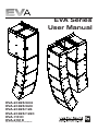
1
EVA Series
User Manual
EVA-2082S/906
EVA-2082S/920
EVA-2082S/126
EVA-2082S/1220
EVA-1151D
EVA-2151D
Electro-Voice EVA Series User Manual
Table of Contents
Rigging-Safety Warning.....................................................................................................................................................3
1.0 Introduction...................................................................................................................................................................4
2.0 Tool List .......................................................................................................................................................................9
3.0 Designing an EVA Array ...........................................................................................................................................9
3.1 Applications for which EVA Arrays are Most Appropriate....................................................................9
3.2 Typical Number of Arrays..............................................................................................................................9
3.3 Determining EVA Array Configuration with EVADATM (EVA Design Assistant) Software............10
3.4 Other Design Examples............................................................................................................................. 16
3.41 Dealing with the Relatively High Low-Frequency Variation of Short Arrays................... 16
3.42 A Five-Module Array Example................................................................................................... 17
3.43 An Eight-Module Array Example.............................................................................................. 19
4.0 Preparing EVA Modules for Installation............................................................................................................... 20
4.1 Recommended Preflight Procedures..................................................................................................... 20
4.2 Module Configuration................................................................................................................................. 20
5.0 EVA Rigging System................................................................................................................................................ 23
5.1 Overview of the EVA Flying System........................................................................................................ 23
5.2 Deciding which Grid Configuration to Use with an EVA Array......................................................... 24
5.21 Standard Grid with or without Second Spreader Bar........................................................ 24
5.22 Extended Grid with or without Second Spreader Bar........................................................ 25
5.23 Coupler Grid with or without Second Spreader Bar.......................................................... 26
5.24 Use of Two Standard Grids....................................................................................................... 26
5.25 EVA-1151D Tie Plates............................................................................................................... 27
5.3 Assembling and Flying an EVA Array...................................................................................................... 28
6.0 Rigging-Strength Ratings and Safety Factors.................................................................................................. 29
6.1 Working-Load Limit and Safety Factor Definitions.............................................................................. 29
6.2 Structural-Rating Overview....................................................................................................................... 30
6.3 Simplified Structural-Rating Guidelines................................................................................................. 31
6.4 Special Rules when Flying EVA-2151D Subwoofer Modules.......................................................... 33
6.5 EVA Structural Rating Charts................................................................................................................... 34
6.6 Electro-Voice Structural-Analysis Procedures..................................................................................... 36
7.0 Rigging Inspection and Precautions..................................................................................................................... 37
8.0 References................................................................................................................................................................. 38
8.1 Rigging (Printed)......................................................................................................................................... 38
8.2 Mechanical Engineering (Printed)........................................................................................................... 38
8.3 Rigging (Websites)..................................................................................................................................... 39
Notes................................................................................................................................................................................... 39
2
Electro-Voice EVA Series User Manual
Rigging-Safety Warning
This document details general rigging practices appropriate to the entertainment industry, as they would
apply to the rigging of Electro-Voice EVA loudspeaker systems. It is intended to familiarize the reader
with standard rigging hardware and techniques for suspending EVA loudspeaker systems overhead. Only
persons with the knowledge of proper hardware and safe rigging techniques should attempt to suspend
any sound systems overhead. Prior to suspending any Electro-Voice EVA loudspeaker systems overhead,
it is essential that the user be familiar with the strength ratings, rigging techniques and special safety
considerations outlined in this manual. The rigging techniques and practices recommended in this manual
are, of necessity, in general terms to accommodate the many variations in loudspeaker arrays and rigging
configurations. As such, the user is expressly responsible for the safety of all specific EVA loudspeaker array designs and rigging configurations as implemented in practice.
All the general rigging material contained in this manual is based on the best available engineering information concerning materials and practices, as commonly recognized in the United States, and is believed
to be accurate at the time of original printing. As such, the information may not be directly applicable in
other countries. Furthermore, the regulations and requirements governing rigging hardware and practices
may be superseded by local regulations. It is the responsibility of the user to ensure that any Electro-Voice
loudspeaker system is suspended overhead in accordance with all current federal, state and local regulations.
All specific material concerning the strength ratings, rigging techniques and safety considerations for
the EVA loudspeaker systems is based on the best available engineering information concerning the use
and limitations of the products. Electro-Voice continually engages in testing, research and development
of its loudspeaker products. As a result, the specifications are subject to change without notice. It is the
responsibility of the user to ensure that any Electro-Voice loudspeaker system is suspended overhead in
accordance with the strength ratings, rigging techniques and safety considerations given in this document and any manual update notices. All non-Electro-Voice associated hardware items necessary to rig a
complete EVA loudspeaker array (chain hoists, building or tower supports and miscellaneous mechanical
components) are the responsibility of others.
Electro-Voice
February 2011
Electro-Voice EVA Series User Manual
3
1.0 Introduction
The Electro-Voice EVA (Expandable Vertical Array) loudspeaker systems or line-array modules represent
an important step in line-array technology for small- and medium-scale fixed-installation sound reinforcement. The various models are designed to significantly simplify the physical assembly of a line array. Also,
arrays of EVA full-range modules are designed to be powered from one amplifier channel, the necessary
crossover and EQ functions accomplished with sophisticated passive networks. The individual loudspeaker drivers, Hydra™ plane-wave generators, acoustic waveguides, enclosures and rigging hardware were
all designed specifically for the EVA product line to not only achieve the highest acoustic output with the
highest fidelity but also produce a precise wavefront from each element to achieve state-of-the-art linearray performance. The EVA subwoofer modules are designed to compliment both the appearance and
performance of the EVA full-range modules in applications where additional low-frequency output is desired from a flown array. A brief description of the product line is included below. The various EVA series
modules are shown in Figure 1 with key dimensions and features.
Although the EVA full-range modules shown in Figure 1 are not physically symmetrical, their acoustic polar
responses are substantially symmetrical. Thus, stereo left and right arrays or left-center-right arrays may
be constructed with the modules in their normal right-side-up orientation as shown in Figure 1. However,
should the user desire, the module attachment points are such that mirror-image left-right arrays can be
made by constructing one array with its modules turned upside down with respect to the views of
Figure 1.
Each EVA full-range module contains two separate, vertically stacked line-array elements splayed within
the module at one-half the included vertical angle of the vertically trapezoidal enclosure. The two elements of each module consist of two vertically stacked EVS2008 8-inch (203 mm) LF drivers (one per
element) and two pairs of DH2005 1.25-inch-diaphragm (32 mm) HF drivers (one pair per element).
Each HF driver pair is mounted on a Hydra™ plane-wave generator, the two of which are vertically stacked
and splayed with their respective elements. Each module effectively functions as one self-contained zone
within an array, with the added benefit of the internal shading network being able to attenuate either the
upper or lower HF driver pair by 3 dB to help smooth transition between zones when needed.
EVA-2082S/906: two-way, LF/HF line-array module with a 90° horizontal x 6° vertical coverage pattern
(for long throws) and passive crossover/HF-shading/EQ network. The enclosure is trapezoidal in the vertical plane with a 6° total included angle. The two line-array elements contained in the module are vertically
splayed by 3°.
EVA-2082S/920: two-way, LF/HF line-array module with a 90° horizontal x 20° vertical coverage pattern (for short throws) and passive crossover/HF-shading/EQ network. The enclosure is trapezoidal in
the vertical plane with a 20° total included angle. The two line-array elements contained in the module are
vertically splayed by 10°.
EVA-2082S/126: two-way, LF/HF line-array module with a 120° horizontal x 6° vertical coverage pattern
(for long throws) and passive crossover/HF-shading/EQ network. The enclosure is trapezoidal in the vertical plane with a 6° total included angle. The two line-array elements contained in the module are vertically
splayed by 3°.
4
Electro-Voice EVA Series User Manual
1.0 Introduction (cont’)
EVA-2082S/1220: two-way, LF/HF line-array module with a 120° horizontal x 20° vertical coverage pattern (for short throws) and passive crossover/HF-shading/EQ network. The enclosure is trapezoidal in
the vertical plane with a 20° total included angle. The two line-array elements contained in the module are
vertically splayed by 10°.
EVA-AM: this optional attenuation module mounts on the inside of an EVA-2082S input panel, and attenuates the entire module by 3, 6 or 9 dB. The nominal impedance of an EVA-2082S module is 16 ohms.
Up to six paralleled EVA-2082S modules can be driven from a single amplifier channel capable of driving
a 2.7-ohm nominal impedance (16 ohms ÷ 6 modules = 2.7 ohms).
Up to eight paralleled EVA-2082S modules can be driven from a single amplifier channel capable of driving a 2.3-ohm nominal impedance if at least two of the modules have the optional EVA-AM attenuation
modules installed.
Both single-15-inch and dual-15-inch EVA subwoofer modules are available. Both use the DVX3159A
15-inch (381 mm) woofer designed specifically for subwoofer duty, providing reliable low-frequency performance at high SPL levels with low distortion and solid impact. Subwoofer modules do not have internal passive crossovers and require an active crossover and dedicated amplifier channel(s)
for proper operation.
EVA-1151D: compact single-15-inch subwoofer module capable of being flown either above or behind
an EVA full-range array. This is a rectangular unit with special tie plates that allow for assembly with either
zero or five degrees of splay between modules. It may also be used in a stand-alone subwoofer array or
ground-stacked.
EVA-2151D: large rectangular dual-15-inch subwoofer module designed for use only at the top of an
EVA full-range array. It may also be used in a stand-alone subwoofer array or ground-stacked.
The standard EVA indoor versions are finished in tough EVCoat™. In addition, all EVA modules (except
EVA-2151D) are available in two levels of weather resistance. The FG versions, e.g., EVA-2082/906FGB, are designed for full weather exposure and feature a fiberglass-finished enclosure, stainless-steel
three-layer hydrophobic grille and the CDG dual-gland-nut input-panel cover. The PI versions, e.g., EVA2082S/906-PI, are rated for indirect outdoor exposure only in protected areas, such as under a roof
overhang, and feature a stainless-steel three-layer hydrophobic grille and CDG dual-gland-nut input-panel
cover on an enclosure finished in standard EVCoat. External fasteners on all EVA systems are stainless
steel.
All EVA modules are available in black or white and are supplied with the hardware necessary to fasten
one module to another and two cosmetic end caps, which give the finished array a smooth and uncluttered appearance. (The end caps on FG fiberglass versions are also finished in fiberglass.) Black is indicated by BLK or B at the very end of the complete model number and white is indicated by WHT or W at
the very end of the complete model number, e.g., EVA-2082S/906-BLK and EVA-2082S/906-PIB.
Electro-Voice EVA Series User Manual
5
1.0 Introduction (cont’)
EVA-SG2-BLK and EVA-SG2-WHT: standard grids for typical down angles with small arrays, or top
and bottom suspension for extreme down angles in large arrays of EVA-1151D subwoofer and/or EVA2082S full-range modules. NOT FOR USE WITH EVA-2151D subwoofer.
EVA-EG2-BLK and EVA-EG2-WHT: extended grids for extreme down angles in small to medium arrays
and typical down angles in large arrays. This is the only grid for flying EVA-2151D subwoofers.
EVA-CG: coupler grid for flying EVA-1151D subwoofer modules behind an EVA full-range array.
The three different grid options (EVA-SG2, EVA-EG2 and EVA-CG) are sold separately. Consult
EVADA software for proper grid selection.
NOTE: series 2 grids (EVA-SG2, EVA-EG2) are required to fly EVA subwoofer modules. Older grids (EVA-SG, EVA-EG) are for flying EVA fullrange modules ONLY.
EVA-GXB-BLK and EVA-GXB-WHT: optional second spreader bars for EVA grids, to be used when
two-point front-to-back hangs are desired. Note: the need to maintain sufficient pressure on the forward
rigging point will limit the amount of down angle available with the standard EVA grids (EVA-SG or EVASG2) in this configuration.
CDG: optional dual-gland-nut input-panel cover to protect the input connections from water. Note that
this cover is supplied with the weather-resistant versions of EVA modules.
CSG: optional single-gland-nut input-panel cover to protect the input connections from water.
CDNL4: optional input-panel cover equipped with dual Neutrik Speakon® NL4 connectors, providing a
quick-disconnect alternative to the standard Phoenix screw-terminal input connectors.
6
Electro-Voice EVA Series User Manual
1.0 Introduction (cont’)
Spreader Bar
Attach Holes
Top View
Right View
Front View
Rear View
Left View
Bottom View
Figure 1a:
EVA-2082S/906 or EVA-2082S/126 dimensioned views
Spreader Bar
Attach Holes
Top View
Right View
Front View
Rear View
Left View
Bottom View
Figure 1b:
EVA-2082S/920 or EVA-2082S/1220 dimensioned views
Electro-Voice EVA Series User Manual
7
1.0 Introduction (cont’)
Spreader Bar
Attach Holes
Top View
Right View
Front View
Left View
Rear View
Figure 1c:
EVA-1151D dimensioned views
Spreader Bar
Attach Holes
Top View
Right View
Front View
Left View
Rear View
Figure 1d:
EVA-2151D dimensioned views
8
Electro-Voice EVA Series User Manual
2.0 Tool List
Listed below are the tools required to assemble an EVA array:
1.
2.
3.
Phillips #2 screwdriver (for attaching cosmetic end panels).
6-mm Allen (hex) wrench (for attaching tie plates and assembling grids).
3/16-inch flat-blade screwdriver (for attaching signal wires to input-panel connectors).
3.0 Designing an EVA Array
NOTE: When flown in the same column with full-range modules from an EVASG2 or EVA-EG2 grid, subwoofers must always be at the TOP of the array.
3.1 Applications for Which EVA Arrays Are Most Appropriate
The total included vertical angles of the EVA modules in side view (6° for long throw and 20° for short
throw) were determined after making many array simulations with the EVA Design Assistant (EVADA™)
software (described in some detail below). Optimum maximum distance for uniform front-to-back coverage is 100 ft ±25 ft.
In side view, a quick rule of thumb for aiming a three- or four-box array in a venue with a flat floor is to have
a line running through the intersection of the top two modules intersect the head of the person in the last
row. This situation is shown in Figure 2.
Figure 2:
Rule-of-thumb for aiming three- and four-module EVA arrays
3.2 Typical Number of Arrays
Line-array systems usually consist of vertical columns of multiple independent line-array elements. The
most common implementation is probably a stereo sound reinforcement system with two columns (left
and right). Additional columns are sometimes added to cover different seating sections of a venue, e.g.,
seating areas that wrap around the side or back of a stage. An additional column is also used in left-center-right configurations, with the center channel for speech. In some venues, where stereo is not desired,
good coverage can be obtained with a single array. A variation of such a monaural system is the exploded
array, where two or more widely spaced (on the order of 10 ft or more) arrays are used to provide the
horizontal coverage required. Also, a large number of arrays may be used in distributed systems, such as
in an arena.
Electro-Voice EVA Series User Manual
9
3.0 Designing an EVA Array (cont’)
3.3 Determining EVA Array Configuration with EVADA™ (EVA Design Assistant) Software
EVADA™ is Excel-spreadsheet-based software for determining optimum array configurations for a given
venue and trim heights. The latest version of EVADA is downloadable from the Electro-Voice Web site
(www.electrovoice.com).
Briefly, one models the room along the horizontal aiming axis of the array, then builds the array of longand/or short-throw modules that produces the most even coverage front to back. (As described above,
EVA modules come in two horizontal coverage angles, 90° and 120°. Following industry convention, these
angles are defined where output is 6 dB down from the maximum [usually on axis] output. Choose the
horizontal angle that provides good coverage of the audience in plan view but minimizes energy directed
on reflective wall surfaces, which energizes the room and lowers the intelligibility of the sound system.)
EVADA displays coverage in three frequency bands. The default bandwidth is one-third octave. The default frequencies are 500 Hz, 3,000 Hz and 8,000 Hz. 3,000 Hz is very important for voice intelligibility.
8,000 Hz is important for “sparkle.” 500 Hz (and below) is important for maintaining a good spectral balance throughout the venue. Longer arrays provide low-frequency uniformity closer to the mid- and highfrequency performance of the array. These effects can be easily seen in EVADA. In addition, the frequencies and bandwidths can be modified by the designer.
EVADA includes an extensive help file but the following overview will provide a good introduction.
Figure 3 shows the Venue tab of the EVADA spreadsheet, where the room information is entered, including dimensions, head height, stage specs (optional) and the so-called “acoustic reference point.” This is
the point in the venue where EVADA makes its sound-pressure level (SPL) calculations and is AUTO set
to head height at point “B”. Clicking on the MANUAL tab allows a different point to be entered.
Figure 3:
EVADA Venue tab, where room information is entered
TM
10
Electro-Voice EVA Series User Manual
3.0 Designing an EVA Array (cont’)
Figure 4 shows the EVADA Main tab, where the array is built and its performance evaluated in the three
frequency bands mentioned above. This tab is full of information and things to enter:
1.
2.
3.
4.
5.
In the top middle of the view is where the number of suspension points (one or two, front to
back), array trim height and distance downstage from front of rig are chosen. Regarding trim
height, be sure to allow for the height of the lifting mechanism(s) and attachment points.
At the top right of the view is where the three frequency bands and their bandwidths are
shown. The default bandwidth is 0.33 octave and the default frequencies are 3,000 Hz, 500 Hz and 8,000 Hz. These can be changed by the user.
The Loudspeaker Stack column and table at the upper left allows the user to (1) choose the
grid (click on the default grid cell to access a selection menu), (2) adjust the grid tilt angle,
and (3) select a combination of EVA modules to array. The HF Attenuator column contains
cells which show the effect of the internal 3-dB high-frequency attenuator (high-frequency
shading): no attenuation or attenuation of either the upper or lower high-frequency driver
pair. The Optional Attenuator column contains cells which show the effect of the optional
EVA-AM attenuator module: 0 dB (not installed), or 3 dB, 6 dB or 9 dB (installed).
Once the elements of items 1 and 3 are complete, clicking on the yellow Update Prediction
button will calculate array performance. This button appears in the Main Cluster geometry
view immediately under the words “MAIN CLUSTER GEOMETRY”. The module vertical
aiming angles are also displayed, with a different colored, slightly splayed line pair for each
module (as noted in Section 1.0, there are two line-array elements in each EVA module, vertically splayed by 3° or 10°, depending on model). If the Show Polars box is checked under
Options, the vertical polar responses of the array are also shown in this area, in the three
frequency bands and bandwidths chosen. The acoustic reference point described earlier is
the small plus sign shown near the rear of the seating area.
The most important predicted information is shown in the Main Cluster SPL graph below
the Main Cluster Geometry view. This shows the predicted coverage uniformity front (left)
to back (right) in dB, where 0 dB is the value shown in the upper right-hand corner of the
Main Cluster SPL view. (In Figure 4, this value is 105 dB SPL.) Note that SPL prediction is
a complex function of the array maximum output versus frequency, the spectral distribution
and peak-to-average ratio of the program material, the dynamic peak capability of the power
amplifiers, and room acoustics. However, the EVADA calculated SPL value has been found
to be close to the peak indications, e.g., peak pointer readings, on a sound level meter with
C or F (flat) weighting in its fast averaging mode under the following conditions: (1) typical
broadband contemporary music program, (2) two arrays operating in a reverberant environment and (3) using the power amplifiers recommended in the engineering data sheets
(available at www.electrovoice.com). (A one-array design would reduce the predicted SPL
by 3 dB.)
Electro-Voice EVA Series User Manual
11
3.0 Designing an EVA Array (cont’)
Producing the most uniform front-to-back coverage is an iterative process. In general, it will be found that:
1.
2.
The top-most module will be aimed above the last-row heads. This may appear to aim array output at the back wall, which if reflective could produce audible delayed signals in the
front of the room. However, reference to the 3,000- and 8,000-Hz vertical polar responses
shows that maximum array output is aimed at the rear-most heads, not at the rear wall.
The lower modules will be attenuated. This is required because the lower modules are so
much closer to the seats they cover than are the upper modules.
Coverage uniformity of ±3 dB front to back is a good goal for mid and high frequencies. At 500 Hz and
below, such uniformity may not be attainable, particularly for short arrays (see additional comments in Section 3.41).
Figure 4:
EVADATM Main tab, where the array is built and performance is displayed in three frequency bands
12
Electro-Voice EVA Series User Manual
3.0 Designing an EVA Array (cont’)
Figure 5 shows the Picture tab of the EVADA spreadsheet, with a side view of the array and its suspension. The array is drawn to scale, in feet or meters as selected in the Units tab on the Venue page (English
or metric, respectively). The grid tilt angle may be adjusted in this tab. One- or two-point rigging can be
selected. Diagnostic messages will appear in the Messages cell, as needed.
Figure 5:
EVADATM Picture tab
Electro-Voice EVA Series User Manual
13
3.0 Designing an EVA Array (cont’)
Figure 6 shows the Report tab of the EVADA spreadsheet, showing such details as hang points (in this
example, pinhole 0 on the centerline of the EVA-CG coupler grid), type of hang point (main or pullback), load (lb or kg), modules in the array and their vertical aiming angles (note that the module inclination
angle is measured at the rear panel of the module).
Figure 6:
EVADATM Report tab, with many physical array details
The Subwoofers tab allows the user to assemble subwoofer arrays and assess the inevitable multiplesource interference that occurs when two or more arrays are displaced horizontally. This is done by
showing the horizontal polar response of subwoofer arrays at three frequencies. The default frequencies
are 100, 80 and 60 Hz but can be changed. The option of changing the polarity of each subwoofer and
inserting up to 9.9 ms of delay in any one group of subwoofers is available. These options may be found to
smooth the interference patterns.
The Preferences tab allows the user to change the colors associated with each array element or module.
Refer to the Preferences help file for details.
14
Electro-Voice EVA Series User Manual
3.0 Designing an EVA Array (cont’)
The Cable Loss tab allows the user to enter the combined impedance of an EVA array and the length and
gauge (AWG) of the wire feeding it, in order to calculate the level lost (dB) in the cable feeding the array.
See Figure 7.
Figure 7:
EVADA Cable Loss tab, calculates the dB level lost in speaker wiring as a function
of the wire gauge (AWG) and length
TM
The Notes tab is a place to enter comments on the particular design.
The Supported Products tab shows both the EVA main array products and other Electro-Voice subwoofers which are suitable for use with EVA arrays. These vary in maximum acoustic output ability and lowfrequency cut-off frequency. The Electro-Voice Web site (www.electrovoice.com) has detailed information
on the subwoofers listed.
Electro-Voice EVA Series User Manual
15
3.0 Designing an EVA Array (cont’)
3.4 Other Design Examples
3.41 Dealing with the Relatively High Low-Frequency Variation of Short Arrays
The example of Figure 4 is a three-module array addressing a flat floor from a trim height of 23 feet, with
the first row 10 feet away and the last row 80 ft away. The array has been aimed 10° down in accordance
with the accepted practice of aiming single loudspeakers or vertical clusters of conventional loudspeakers. High frequency coverage (important for vocal intelligibility) is a fairly uniform ±3 dB from front to back
throughout the venue. At 500 Hz, however, the coverage is distinctly biased, rising from -2 dB in front
to a high of +7 dB about 25% of the way back, then falling gradually back to -3 dB at the rear. This is
a function of the relatively short (4.7 ft) three module array. The variation at 100 Hz (not shown) is even
greater, falling from +9 dB at the front to -2 dB at the rear. This means that if the sound is well balanced
at point “B” (a likely FOH location), it will be “tubby” or “boxy” up front and intelligibility may suffer.
Figure 8 shows the same venue and modules with an array design that provides more uniform “tracking” of the three frequencies. Attenuation has been applied to both the upper and lower modules and
the tilt angle has been raised from -10° to -1°. At first glance, this would appear to be wasting energy on
the back wall, but polars show the all-important main lobe to be aimed at the last row of seats instead.
Spectral balance of the three frequencies is now smooth and uniform throughout most of the venue and
level variance is a very acceptable +4 dB to -3 dB as dictated by the 500 Hz response of the 4.7 ft array
length.
16
Figure 8:
A three-module EVA example of Figure 4, modified to improve the
front-to-back “tracking” of all three predicted frequencies
Electro-Voice EVA Series User Manual
3.0 Designing an EVA Array (cont’)
3.42 A Five-Module Array Example
Figure 9a shows a five-module array of EVA-2082S modules in a 100-ft-deep venue with a flat floor and a small
balcony/choir loft at the rear typical of many house-of-worship environments. The three frequencies not only track
very well but nearly all the main floor is within ± 3 dB front to back. Balcony maintains good spectral balance at a
slightly lower SPL. This desirable situation is helped by not only the 3 dB attenuation of the top element but also by
the array being longer than in the previous example (8.0 ft versus 4.7 ft). Note also the progressive attenuation of
the bottom three elements, made possible by combining an EVA-AM installed in the bottom module with the builtin HF shading of the lower elements of the bottom two modules. To accomplish this with a typical active line array
would have required six additional channels of amplification and processing.
This venue has a ceiling height of twenty four feet, which after allowing for hoist and rigging, results in a trim height
of only twenty two feet. The excellent vertical directivity of the five module array keeps excess energy off the low
ceiling and results in improved intelligibility throughout the venue while maintaining over fourteen feet of clearance
from the floor to the bottom of the array. The customer also wants subwoofers but there is no place to put them on
the main floor. The subs will have to be flown, and will require three EVA-1151D or two EVA-2151D subwoofer
modules to acoustically balance the output of five full range modules. Figure 9b shows the five module full range
array with subs mounted in their normal position on top. This configuration results in less than nine feet of clearance
at the bottom of the array and requires extreme attenuation of the bottom modules. The front to back coverage,
while still acceptable, has been compromised by the full range array being too low to the floor. The whole array can
be shortened, but at the expense of uniform coverage as seen in the earlier examples. Figure 9c shows the ideal
solution. Three EVA-1151D subwoofer modules are flown behind the five module full range array on an EVA-CG
Coupler Grid. Coverage, trim height and ground clearance are all essentially identical to the original five module
array without subs.
Figure 9a:
A five-module EVA example whose three predicted frequencies not only track well
front-to-back, but also fall mostly within the desired ±3 dB
Electro-Voice EVA Series User Manual
17
3.0 Designing an EVA Array (cont’)
Figure 9b:
The same venue with subwoofers at the top of the main array. Bottom of the array is too low and
coverage uniformity has suffered as a result, even with a second EVA-AM installed.
Figure 9c:
The same venue with subwoofers flown behind the main array on an EVA-CG Coupler Grid. Coverage,
trim height and ground clearance are essentially identical to the same array without subwoofers.
18
Electro-Voice EVA Series User Manual
3.0 Designing an EVA Array (cont’)
3.43 An Eight-Module Example
Figure 10 shows an eight-module array in a large theater with two balconies. Note that this array cannot
be driven from one amplifier channel because only one of the modules uses the optional EVA-AM attenuation module. (An eight-module EVA array can be driven from an amplifier capable of driving a 2.3-ohm
nominal impedance if two of the modules have attenuation modules installed. A solution is to use two
amplifier channels, one for the top four modules and one for the bottom four. In order to preserve the predicted array coverage, be certain that the voltage gains of both channels are the same.)
Nearly all of the 100-ft-deep main floor is covered within the optimum ±3 dB at all three predicted frequencies. The same uniformity applies to the first balcony (108 ft at the rear wall) although the average
level drops by about 3 dB. The upper balcony (also 108 ft at its rear wall) shows a bit wider variation and
less uniform tracking of the three predicted frequencies. However, the total variation in the upper balcony
is still within ±3 dB.
Figure 10:
A eight-module EVA example in a large theater with two balconies
(see text above for more details)
Electro-Voice EVA Series User Manual
19
4.0 Preparing EVA Modules for Installation
4.1 Recommended Preflight Procedures
For any installed sound system, certain checks made at the installer’s place of business can prevent expensive on-site delays. A short-list follows, and sets the stage for proper array performance:
1.
2.
3.
4.
Unpack all loudspeakers in the shop.
Check for proper model numbers.
Check the overall condition of the loudspeakers.
Check for continuity at the loudspeaker inputs.
It is a good idea, once on site and the loudspeakers are connected, to check again for continuity at the
power-amplifier end.
4.2 Module Configuration
After the EVADA software has been used to design an appropriate array, the high-frequency (HF) shading
or use of the optional attenuation modules should be noted. In this way, these settings and options can
be configured on the systems as they are rigged together and suspended. (The shading adjustments and
installation of attenuation modules can be completed at the installer’s shop but then care must be taken to
see that the EVA modules are properly identified to avoid misassembly of the array in the field.)
Figure 11 shows an EVA HF shading switch card. This card comes pre-inserted in the “Center = Both @
0 dB” position, indicating no shading of either HF element.
Figure 11a:
EVA input panel as supplied,
with the high-frequency (HF)
shading switch card in its
central, 0 dB position
20
Figure 11b:
EVA input panel, with the
switch card inserted to shade
the lower HF element 3 dB
Figure 11c:
EVA input panel, with the
switch card inserted to shade
the upper HF element 3 dB
Electro-Voice EVA Series User Manual
4.0 Preparing EVA Modules for Installation (cont’)
To attenuate the top HF element, remove the switch card by drawing it toward you using the central finger
hole. (The switch can also be removed with the end of a flat-blade screwdriver, by placing the blade end
in the switch hole and using the adjacent edge of the input panel as a fulcrum. To facilitate this operation,
there is a small recess in the edge of the input panel adjacent to the hole in switch card.) Reinsert the
switch card one step higher to shade the upper HF element by 3 dB. Reinsert the switch card one step
lower to shade the lower HF element.
The EVA-AM is for use only with EVA-2082S full-range modules.
Some array designs will also use one or more of the optional EVA-AM attenuation modules. These attach
to the inside of the input-panel assembly using the following steps:
1.
2.
3.
4.
5.
6.
7.
Remove the input-panel assembly by removing its eight holding screws with a Phillips #2
screwdriver. The cable assembly that connects the input-panel’s green PC board to the
crossover/equalizer network inside the EVA module is long enough to allow the input-panel
assembly to rest on a flat surface close to the EVA module. If necessary, the crossover/
equalizer cable can be temporarily disconnected. The removed input-panel assembly is
shown in Figure 12.
Unplug and discard the 7-pin jumper-wire connector. The attenuation module’s cable connector will replace this connector.
With the mounting straps on top, place the attenuation module into the pocket between the
four bosses adjacent to the PC board and secure with the four screws (provided).
Plug the attenuation module’s cable into the 7-position header on the PC board as shown in
Figure 13.
Apply the supplied label to the input panel around the input connectors as shown on the
EVA-AM Instruction Sheet.
Reinstall the input-panel assembly.
Connect a short piece of wire (supplied) from the “SELECT” terminal to the terminal marked
-3, -6 or -9 dB, as determined by EVADA.
Electro-Voice EVA Series User Manual
21
4.0 Preparing EVA Modules for Installation (cont’)
Figure 12:
EVA input panel removed, showing green PC board and the four bosses
to which the optional EVA-AM attenuation module will be attached
22
Figure 13:
EVA input panel with EVA-AM installed showing connector plug-in
Electro-Voice EVA Series User Manual
5.0 EVA Rigging System
5.1 Overview of the EVA Flying System
The external rigging parts supplied with each EVA line-array module attach to internal metal parts running top-to-bottom in each module, so that a finished array places no stress on the wooden enclosure
parts. The rigging simplification inherent in the EVA modules is based on the final array being assembled
in a fixed manner as a single rigid structure. When flown as a single vertical column with EVA full-range
modules, EVA subwoofer modules must always be assembled at the top of the array with no splay between them. The EVA full-range enclosures are vertically trapezoidal—taller at the front than at the back.
One module is fastened to another with the bottom of one in contact with the top of another. The vertical
aiming angle between the two modules is fixed by their vertical draft angles. The draft angle is 3° for the
EVA-2082S/906 and EVA-2082S/126 long-throw modules and 10° for the EVA-2082S/920 and EVA2082S/1220 short-throw modules, producing 6°, 13° or 20° between any two modules, depending on
which modules are attached together. (The specific selection of long- and short-throw modules and their
arrangement is dependant on room geometry and trim height. These choices are facilitated by ElectroVoice’s EVA Design Assistant [EVADA™], software available on the EV Web site, www.electrovoice.com.
See section 3.0 Designing an EVA Array above.) Each EVA module is attached to the module below it
by the supplied pair of side-mounted tie plates. After the array is assembled, cosmetic end caps, one
for each side of each module, are attached to the enclosure, hiding the structural tie plates and giving a
smooth, attractive array appearance.
A basic array is shown in Figure 14, which illustrates the basic components that make up the EVA flying
system.
EVA Grid
EVA Modules
Attach Spreader Bar
with M10 Shoulder
Bolts and Nylon
Washers Supplied
with Grid
Spreader
Bar
Grid
Side
Arm
Attach Grid Side
Arms with M10 Bolts
Supplied
Attach Tie Plates with
M10 Bolts Supplied
Nylon
Washer
M10
Shoulder
Bolt
Tie Plates
(2 Supplied with
each EVA Module)
EVA Module
Grid Assembly Detail
Note: Cosmetic End
Panels Not Shown
Electro-Voice EVA Series User Manual
Figure 14:
Typical EVA flying system
23
5.0 EVA Rigging System (cont’)
While the majority of EVA applications will be accommodated with full-range arrays of three or four modules, up to eight EVA-2082S and/or EVA-1151D modules may be suspended together up to a combined
maximum loudspeaker column weight of 720 lb (327 kg). When EVA-2151D subwoofers are used, the
combined maximum loudspeaker column weight is 840 lb (381 kg), or five EVA-2082S modules under
two EVA-2151D modules. When subwoofers are used, they must be installed at the top of the array.
5.2 Deciding Which Grid Configuration to Use with an EVA Array
5.21 Standard Grid with or without Second Spreader Bar
The EVA-SG2 standard grid is shown in Figure 15. This grid is appropriate for that majority of applications covered by a three- to four-module full-range array. It comes with one spreader bar and two side
arms, plus the two shoulder bolts and nylon washers required to assemble the three parts into a grid. The
spreader bar has three 0.813-inch (20.6 mm) holes through it, one near each end and one in the center,
to which the chain hoist(s) or other device(s) used to lift the array into position can be attached. Using the
two end points provides horizontal stability for the array. Using the center point alone will probably require
a tie-off to stabilize the horizontal position of the array.
Standard (EVA-SG2)
Sidearm
Spreader Bar
Standard (EVA-SG2)
Sidearm
EVA Module(s)
(Not Included with Grid)
Figure 15:
EVA-SG2 grid (down angle of the array is determined by
the front-to-back position of the spreader bar)
When the standard grid with its single spreader bar is used, the down angle of the array is determined by
the front-to-back attachment position of the spreader bar. This information is provided by Electro-Voice’s
EVA Design Assistant (EVADA™), a function of the array makeup and desired vertical aiming. See section
3.0 Designing an EVA Array.
For arrays (1) larger than four EVA modules or (2) three- to-four-box arrays which require more down
angle than what is available with a standard grid, the extended grid is usually required. See section 5.22
Extended Grid with or without Second Spreader Bar.
24
Electro-Voice EVA Series User Manual
5.0 EVA Rigging System (cont’)
A second spreader bar, EVA-GXB, is available (sold separately). The second spreader bar is used when
two front-to-back pickup points are desired/required. Figure 16 shows an EVA-SG2 grid with a second
spreader bar. When two spreader bars are used, one is attached to the extreme front hole positions in the
side arms and the other is attached to the extreme rear position. This gives the most control over the vertical aiming of the array. Note that the need to maintain sufficient load on the front spreader bar to maintain
rigging tension will diminish the amount of down angle available with a standard grid. For this reason the
EVA-EG2 extended grid is probably a better choice when using front-to-back pickup points.
Standard (EVA-SG2)
Sidearm
Second (EVA-GXB)
Spreader Bar
(Sold Separately)
Standard (EVA-SG2)
Sidearm
Spreader Bar
Figure 16:
EVA-SG2 standard grid with optional
EVA-GXB spreader bar
EVA Module(s)
(Not Included with Grid)
5.22 Extended Grid with or without Second Spreader Bar
The EVA-EG2 extended grid is also available. Arrays taller than four modules will probably require the extended grid, whose side arms are 11 inches longer to the rear. Three- to four-module arrays which require
more down angle than what is available with a standard grid will also require the extended grid. Figure 17
shows the extended grid.
Extended (EVA-EG2)
Sidearm
Spreader Bar
Second (EVA-GXB)
Spreader Bar
(Sold Separately)
Extended (EVA-EG2)
Sidearm
Figure 17:
EVA-EG2 extended grid (shown with
optional EVA-GXB spreader bar)
EVA Module(s)
(Not Included with Grid)
Electro-Voice EVA Series User Manual
25
5.0 EVA Rigging System (cont’)
5.23 Coupler Grid with or without Second Spreader Bar
The EVA-CG is shown in Figure 18. This grid is used to fly up to three
EVA-1151D subwoofer modules in an array behind up to five EVA2082S full-range modules and is an ideal solution when subs must be
flown and trim height is limited. The included spreader bar allows for
single-point suspension, two-point side-by-side suspension, or, with
the addition of an optional second EVA-GXB spreader bar, two-point
front-to-back suspension.
EVA-GXB
Spreader Bar
EVA-CG
Coupler Grid
5.24 Use of Two Standard Grids
Two EVA-SG2 standard grids may also be used with an EVA array,
one attached to the upper module and the other attached to the lower
module, acting as a pull-up grid. This is a way to achieve extreme down
angles, such as might be encountered in a distributed arena system.
Figure 19 shows this configuration. When using two grids in this fashion, the angle between the suspension lines must never be allowed to
exceed 60°. Do not use EVA-CG, EVA-EG or EVA-EG2 extended
grids in this application. For overall down angles of about 45° or
greater, use the third-to-last hole of each grid. For overall down angles
of less than about 45°, use the third-to-last hole on the bottom grid and
any hole forward of third-to-last on the top grid. See Figure 19.
Figure 18:
The use of EVA-CG coupler grid
to array EVA-1151D’s behind
EVA-2082S’s
EVA-SG2
Standard Grid
EVA Module(s)
EVA-SG2
Standard Grid
26
Figure 19:
The use of two EVA-SG2 standard grids to achieve extreme down angles
Electro-Voice EVA Series User Manual
5.0 EVA Rigging System (cont’)
5.25 EVA-1151D Tie Plates
The tie plates included with each EVA-1151D module facilitate the assembly of multiple EVA-1151D
modules in a vertical column at either zero or 5 degrees of splay between modules. They also provide the
attachment points for suspending EVA-2082S modules underneath. Another feature is the ability to invert
these tie plates and install at the top of an EVA-1151D module with an optional EVA-GXB spreader bar to
serve as a rudimentary flying grid for a stand-alone subwoofer hang if only minimal down angle is required.
See Figure 20. Note that EVA-1151D tie plates may be used as a suspension grid ONLY in conjunction
with an EVA-GXB spreader bar (sold separately).
Attach EVA-GXB Spreader Bar Using These Holes
Attach to Top of
Upper EVA-1151
Using These
Holes
Attach to Top of
EVA-1151 Using
These Holes
Attach Upper
EVA-1151 Using
These Holes
Attach
EVA-1151 Using
These Holes
Attach Lower
EVA-1151 Using
These Holes
Attach
EVA-2082 Using
These Holes
EVA-1151 to EVA-1151 Array,
0° Splay Between Enclosures
EVA-1151 to EVA-1151 Array,
5° Splay Between Enclosures
EVA-1151 to EVA-2082 Array,
0° Splay Between Enclosures
Figure 20:
EVA-1151D tie plate configurations (left side shown, right side mirrored)
Electro-Voice EVA Series User Manual
27
5.0 EVA Rigging System (cont’)
5.3 Assembling and Flying an EVA Array
On each end of an EVA module are a pair of upper and lower connection points that accept the supplied
M10 flathead bolts to either (1) attach the side arms of an EVA-grid to the top of the upper array module,
(2) attach the tie plates supplied with each module so that the modules can be attached to each other or
(3) attach an EVA-SG2 grid to the bottom module for use as a pull-up point. Figure 14 identifies these
parts.
The first step in assembling an array is to attach the two side arms of the grid to the upper array module.
Attach the side arms with the M10 bolts supplied and tighten securely. A single spreader bar is then attached to the side-arm holes shown in EVADA that provide the desired array aiming angle. See section
3.0 Designing an EVA Array. When two spreader bars are used they should be attached to the extreme
front and back positions on the side arms, for maximum control over the array’s vertical aiming angle.
Attach a chain hoist(s) or other lifting device(s) to the assembled grid and the upper EVA module. Then
take the following steps:
1. Lift the assembly to the point where the second EVA module can just be slipped under the suspended partial array.
2. Using four M10 flathead screws (provided) attach a tie plate (flat end to the rear) to each end of
the suspended module but do not fully tighten screws.
3. Move the second module into place under the suspended module between the tie plates.
4. Align the holes in the tie plates with the corresponding holes in the lower module and assemble to
the one above with four M10 flathead screws (provided).
5. Fully tighten all eight M10 screws.
6. Connect the input terminals of the uppermost full-range module in parallel with the EVA full-range
modules below it. Subwoofer modules require a dedicated amplifier channel and may need to be
wired individually according to their combined impedance and the drive capabilities of the amplifier.
Repeat the steps above for attachment of additional EVA modules.
After the last module is attached, even though a tie plate will not be
attached to its bottom end panels, install a pair of M10 screws per end
panel where the tie plate would have attached in order to prevent audible air leaks.
Complete the array by attaching the cosmetic end panels, using the M5 screws supplied for each panel.
Tighten the screws by hand or use a power drill with a moderate torque setting. Over tightening will drive
the screws through the wood of the end panels!
An array will typically be fed from the top down and it is recommended that as each module is added to
the array it should be wired to the one above (except for subwoofer modules as noted above) and the
shading selector position set and verified per EVADA. Attenuation modules (if needed) may also be installed at this time. Note that shading and/or attenuation in the wrong place will seriously detract from the
performance of the completed array!
The completed array may now be hoisted into position and secured in the final way intended.
28
Electro-Voice EVA Series User Manual
6.0 Rigging-Strength Ratings and Safety Factors
6.1 Working-Load Limit and Safety Factor Definitions
The structural ratings for all of the EVA rigging components and complete loudspeaker systems are based
on test results in which parts were stressed to failure. Manufacturers typically present the structuralstrength ratings of mechanical components or systems as either the working-load limit (WLL) or the ultimate-break strength. Electro-Voice chooses to present the structural-load ratings of the EVA loudspeaker
systems as the working-load limit. The working-load-limit rating represents the maximum load that should
ever be applied to a mechanical component or system.
THE USER SHOULD NEVER APPLY A LOAD THAT EXCEEDS THE WORKING-LOAD LIMITS OF ANY OF THE RIGGING COMPONENTS OR COMPLETE LOUDSPEAKER SYSTEMS
DESCRIBED IN THIS MANUAL.
The working-load limits for the EVA rigging components and complete loudspeaker systems described
in this manual are based on a minimum 8:1 safety factor. The safety factor is defined as the ratio of the
ultimate-break strength divided by the working-load limit, where the ultimate-break strength represents the
force at which a part will structurally fail. For example, if a part has a working-load limit of 1,000 lb (454
kg), it would not structurally fail until a force of at least 8,000 lb (3,629 kg) was applied, based on an 8:1
safety factor. However, the user should never apply a load to that part that exceeds 1,000 lb (454 kg). The
safety factor provides a margin of safety above the working-load limit to accommodate normal dynamic
loading and normal wear.
CAUTIONS for Working-Load Limits and Safety Factors
The working-load limits defined by the manufacturer of any rigging component should never be exceeded.
Electro-Voice bases the working-load limits of its EVA products on a minimum of an 8:1 safety factor.
Other manufacturers of rigging components may base their working-load limits on safety factors other
than 8:1. For example, 5:1 safety factors are fairly common amongst rigging manufacturers because many
regulatory agencies call for a minimum safety factor of 5:1.
When an EVA loudspeaker system is installed where local regulations only require a safety factor of 5:1,
Electro-Voice insists that the working-load limits of the EVA rigging never be exceeded and that an 8:1
safety factor be maintained for the EVA loudspeakers.
The user is cautioned that some local regulations may require safety factors higher than 8:1. In that circumstance, Electro-Voice insists that the user maintain the higher safety factor as required by the local
regulations throughout the entire EVA installation. It is the responsibility of the user to make sure that any
EVA installation meets all applicable local, state or federal safety regulations.
Electro-Voice EVA Series User Manual
29
6.0 Rigging-Strength Ratings and Safety Factors (cont’)
6.2 Structural Rating Overview
Designing a safe structural array is ordinarily a very complex process best left to experienced professionals. There are two independent strength considerations that, together, give a complete description of the
overall structural capabilities of any loudspeaker system; these are:
1.
2.
The strength of each individual enclosure rigging point; which is the combined strength of
the internal rigging straps, external tie plates, bolts and enclosure.
The total strength of the overall array; which is a function of the combined forces from all of
the rigging points acting on the rigging components and the array as a whole.
For grids, there are also two independent strength considerations that, together, give a complete description of the overall structural capabilities of the grid; these are:
1.
2.
The strength of each individual grid rigging point; which is the combined strength of the
bolts, grid side arms and spreader bars.
The total strength of the overall grid; which is a function of the combined forces from all of
the rigging points acting on the rigging components and the grid as a whole.
In any system, the forces acting on each loudspeaker (on each individual rigging point and on the overall
enclosure) and the forces acting on each rigging accessory (grids and spreader bars) will vary with each
array configuration. Determining those forces throughout an array requires complex mathematical calculations. Electro-Voice engineers have therefore defined a set of simplified structural-rating guidelines
for EVA systems that eliminate the need for complex calculations. The interaction of the complex forces
throughout EVA arrays was analyzed using a combination of destructive testing and computer modeling to
develop this set of conservative guidelines, presented below, to enable a rigger to immediately determine
on site whether or not an array is safe without having to make weight-distribution calculations.
To make EVA systems both safe and easy to use, Electro-Voice engineers have chosen to treat EVA arrays
as a single unified structure rather than individual components. All the complex factors listed below have
been taken into account to design a rigging system strong enough to maintain a minimum 8:1 safety factor up to a maximum suspended column weight of 720 lb (327 kg) at any elevation (tilt) angle available on
the EVA-SG2 or EVA-EG2 grid with any combination of EVA-1151D and/or EVA-2082S modules. The
maximum suspended column weight for the EVA-CG coupler grid is 760 lb (345 kg). The EVA-2151D
may only be flown from the EVA-EG2 grid. The maximum single-point suspended column weight using EVA-2151D subwoofers is 840 lb (381 kg). See SPECIAL RULES WHEN FLYING EVA-2151D
SUBWOOFER MODULES, section 6.4.
30
Electro-Voice EVA Series User Manual
6.0 Rigging-Strength Ratings and Safety Factors (cont’)
6.3 Simplified Structural-Rating Guidelines
The simplified structural-rating guidelines for EVA loudspeakers are charted in section 6.5. These guidelines were determined based on the:
1.
2.
3.
Vertical elevation possible with EVA-SG2, EVA-EG2 and EVA-CG grids.
Total weight of all enclosures in the array plus accessories, cabling and rigging.
Angled forces acting on rigging components and enclosures.
WHEN APPLYING THE STRUCTURAL RATING GUIDELINES TO ANY EVA LOUDSPEAKER
SYSTEM SUSPENDED OVERHEAD, THE USER MUST OBEY THE FOLLOWING RULES:
1.
2.
3.
4.
5.
Never exceed 720 lb (327 kg) total column weight of suspended EVA-1151D and EVA2082S loudspeakers, accessories and cabling. (Typically any combination of eight EVA2082S and/or EVA-1151D modules.) When flown in the same column with full-range
modules from an EVA-SG2 or EVA-EG2 grid, subwoofers must always be at the TOP of the
array with NO SPLAY BETWEEN MODULES.
If a second grid is used at the bottom of the array, the angle between the suspension lines
must never be allowed to exceed 60° as shown in Figure 19. Do not use EVA-CG, EVAEG or EVA-EG2 grids in this application!
The suspended column must be perpendicular (plumb) to within ±5 degrees as shown in
Figure 21.
If a spreader bar or grid is suspended from two points, the angle between those two suspension lines must not exceed 60° (maximum 30° from plumb each) as shown in Figures 22
and 23.
Never exceed 760 lb (345 kg) total column weight when using the EVA-CG coupler grid.
When flying EVA-1151D modules behind EVA-2082S full-range modules on the EVA-CG
coupler grid, the maximum number of EVA-2082S full-range modules at the front of the grid
is FIVE and the maximum number of EVA-1151D subwoofer modules at the rear of the grid
is THREE. A bottom pull-up is not allowed when using the EVA-CG. Flying a single column from the EVA-CG is not allowed.
Electro-Voice EVA Series User Manual
31
6.0 Rigging-Strength Ratings and Safety Factors (cont’)
Figure 21:
Side-to-side simplified structural-rating guidelines for EVA arrays (angle shown exaggerated
for illustration purposes)
32
Figure 23:
Front-to-back angular pull structural-rating
guidelines for EVA spreader bars
Figure 22:
Side-to-side angular pull structural-rating guidelines for EVA spreader bars
Electro-Voice EVA Series User Manual
6.0 Rigging-Strength Ratings and Safety Factors (cont’)
6.4 Special Rules when Flying EVA-2151D Subwoofer Modules
EVA-2151D subwoofers may ONLY be flown from an EVA-EG2 grid. Because the EVA-2151D modules
have six rigging points instead of four, the maximum load ratings are higher, but also require special conditions to achieve. Please read, understand and observe the following:
1.
2.
3.
When flying EVA-2082S full-range modules below EVA-2151D subwoofer modules, the
maximum number of EVA-2151D modules is TWO and the maximum number of EVA2082S modules is FIVE. A bottom pull-up point may be used as long as the maximum
angle on the grid does not exceed 45° and the maximum pull angle between suspension
lines does not exceed 60°. Maximum single-point column weight when using EVA-2151D
subwoofers is 840 lb (381 kg).
When flying EVA-2151D subwoofer modules as a stand-alone subwoofer array using the
center attachment point on the spreader bar(s), the maximum number of EVA-2151D modules is FOUR, even if two spreader bars are used. For extreme down angles, a second
EVA-EG2 grid may be attached at the bottom of the array for use as a pull-up point as long
as the maximum pull angle between suspension lines does not exceed 60°.
When flying FIVE or more EVA-2151D modules, use only the two outermost attachment
holes on the spreader bar. If two spreader bars are used, the two outermost attachment
holes must be used ON EACH BAR. A maximum vertical column of EIGHT EVA-2151D
modules is permissible under these conditions if the column is kept perpendicular to the
ground. The maximum suspended column weight of EVA-2151D subwoofers in a standalone subwoofer array with 0° of inclination (tilt) angle using both outer attachment points
on the spreader bar is 1,470 lb (667 kg). See Figure 24.
Any Array with more
than (4) EVA-2151D’s
must use the two
outermost attachment holes on the
spreader bar
Any Array with more
than (4) EVA-2151D’s
must use the two
outermost attachment holes on the
spreader bar
Figure 24:
EVA-EG2 grid with more than (4) EVA-2151D’s in a straight (vertical)
array must use outer holes of spreader bar
Never attempt to suspend EVA systems overhead by any other method than the use of EVA-SG2, EVA-EG2 or EVA-CG grids and spreader
bars as outlined in this manual! eva-1151D modules may be suspended from inverted eva-1151d tie plates only in conjunction with an eva-gxb
spreader bar (sold separately).
Electro-Voice EVA Series User Manual
33
6.0 Rigging-Strength Ratings and Safety Factors (cont’)
6.5 EVA Structural Rating Charts
Combinations not listed are not allowed.
Position
1 (Top)
2
3
4
5
6
7
8
2082S modules on EVA-SG2 grid
720 lb (327 kg) max. column weight, any pin hole, any angle.
2082S 2082S 2082S 2082S 2082S 2082S 2082S
2082S 2082S 2082S 2082S 2082S 2082S 2082S
2082S 2082S 2082S 2082S 2082S 2082S
2082S 2082S 2082S 2082S 2082S
2082S 2082S 2082S 2082S
2082S 2082S 2082S
2082S 2082S
2082S
Position
1 (Top)
2
3
4
5
6
7
8
1151D modules over 2082S modules on EVA-SG2 grid
720 lb (327 kg) max. column weight, any pin hole, any angle.
Subs must be at the top of the array with NO SPLAY
between them.
1151D 1151D 1151D 1151D 1151D 1151D 1151D 1151D
2082S 1151D 1151D 1151D 1151D 1151D 1151D 1151D
2082S 2082S 2082S 2082S 1151D 1151D 1151D 1151D
2082S 2082S 2082S 2082S 2082S 2082S 1151D
2082S 2082S 2082S 2082S 2082S 2082S
2082S 2082S 2082S 2082S 2082S
2082S 2082S 2082S
2082S 2082S
Position
1 (Top)
2
3
4
5
6
7
8
1151D modules over 2082S modules on EVA-EG2 grid
720 lb (327 kg) max. column weight, any pin hole, any angle.
Subs must be at the top of the array with NO SPLAY
between them.
1151D 1151D 1151D 1151D 1151D 1151D 1151D 1151D
2082S 1151D 1151D 1151D 1151D 1151D 1151D 1151D
2082S 2082S 2082S 2082S 1151D 1151D 1151D 1151D
2082S 2082S 2082S 2082S 2082S 2082S 1151D
2082S 2082S 2082S 2082S 2082S 2082S
2082S 2082S 2082S 2082S 2082S
2082S 2082S 2082S
2082S 2082S
Position
1 (Top)
2
3
4
5
6
7
2151D modules over 2082S modules on EVA-EG2 grid
840 lb (381 kg) max. column weight, any pin hole.
Angle not to exceed 45° down with bottom pull-up.
2151D 2151D 2151D 2151D 2151D 2151D
2082S 2082S 2082S 2151D 2151D 2151D
2082S 2082S 2082S 2082S 2082S 2082S
2082S 2082S 2082S 2082S 2082S
2082S 2082S 2082S 2082S
2082S 2082S
2082S
34
Maximum Permissible
Column Weight
Spreader Bar
Pin Holes
Grid
Position 1
Position 2
Electro-Voice EVA Series User Manual
6.0 Rigging-Strength Ratings and Safety Factors (cont’)
Position
1 (Top)
2
3
4
5
1151D modules behind 2082S modules on EVA-CG coupler grid
760 lb (345 kg) max. combined column weight, any pin hole. No bottom pull-up allowed.
Front Rear Front Rear Front Rear Front Rear Front Rear Front Rear
2082S 1151D 2082S 1151D 2082S 1151D 2082S 1151D 2082S 1151D 2082S 1151D
2082S
2082S 1151D 2082S 1151D 2082S 1151D 2082S 1151D 2082S 1151D
2082S
2082S
2082S 1151D 2082S 1151D
2082S
2082S
2082S
2082S
Position
1 (Top)
2
3
4
5
6
7
8
Stand-alone array of 1151D modules on EVA-SG2 grid
720 lb (327 kg) max. column weight, any pin hole, any angle.
1151D 1151D 1151D 1151D 1151D 1151D 1151D 1151D
1151D 1151D 1151D 1151D 1151D 1151D 1151D
1151D 1151D 1151D 1151D 1151D 1151D
1151D 1151D 1151D 1151D 1151D
1151D 1151D 1151D 1151D
1151D 1151D 1151D
1151D 1151D
1151D
Position
1 (Top)
2
3
4
5
6
7
8
Stand-alone array of 1151D modules on EVA-EG2 grid
720 lb (327 kg) max. column weight, any pin hole, any angle.
1151D 1151D 1151D 1151D 1151D 1151D 1151D 1151D
1151D 1151D 1151D 1151D 1151D 1151D 1151D
1151D 1151D 1151D 1151D 1151D 1151D
1151D 1151D 1151D 1151D 1151D
1151D 1151D 1151D 1151D
1151D 1151D 1151D
1151D 1151D
1151D
Position
1 (Top)
2
3
4
Stand-alone array of 2151D modules on EVA-EG2 grid
840 lb (381 kg) max. column weight, any pin hole, any angle.
2151D 2151D 2151D 2151D
2151D 2151D 2151D
2151D 2151D
2151D
Position
1 (Top)
2
3
4
5
6
7
8
Stand-alone array of 2151D modules on EVA-EG2 grid, 0° tilt
1470 lb (667 kg) max. column weight at 0° only.
MUST USE BOTH OUTER SUSPENSION POINTS ON
SPREADER BAR(S)
2151D 2151D 2151D 2151D
2151D 2151D 2151D 2151D
2151D 2151D 2151D 2151D
2151D 2151D 2151D 2151D
2151D 2151D 2151D 2151D
2151D 2151D 2151D
2151D 2151D
2151D
Electro-Voice EVA Series User Manual
Maximum Permissible
Column Weight
Spreader Bar
Pin Holes
Grid
Position 1
Position 2
35
6.0 Rigging-Strength Ratings and Safety Factors (cont’)
6.6 Electro-Voice Structural-Analysis Procedures
Electro-Voice maintains a structural pull-test facility in Burnsville, Minnesota USA which includes load
cells with digital-electronic display and recording. The load cells are calibrated annually by an independent
laboratory to a standard traceable to the United States National Bureau of Standards. This pull-test facility
is capable of pulling to destruction both individual rigging components and complete loudspeaker systems.
Electro-Voice utilizes state-of-the-art computer-modeling programs for structural analysis throughout the
development of loudspeaker systems. The computer modeling enables the complex forces in the rigging
components and enclosures to be analyzed for loudspeakers assembled into arrays in both static and
dynamic conditions.
Structural testing and computer modeling were used throughout the engineering development of all EVA
individual rigging components and complete loudspeaker systems described in this manual. Testing and
modeling involving both anticipated use and anticipated misuse were performed as part of the analysis.
Engineering prototypes were stressed to failure and designs were revised based on those test results.
Production systems and components were stressed to failure for verification of the final designs.
36
Electro-Voice EVA Series User Manual
7.0 Rigging Inspections and Precautions
Electro-Voice EVA Loudspeaker Systems: Prior to each use, inspect the enclosures for any cracks,
deformations or missing or damaged components that could reduce enclosure strength. Inspect the tie
plates between enclosures for cracks, corrosion or other deformations that could reduce their strength
and integrity. Check to be sure there are no missing screws and that all M10 rigging bolts are securely
tightened. Hardware that is bent or showing signs of more than cosmetic surface corrosion should be
replaced immediately.
Electro-Voice EVA Grids: Prior to each use, inspect the grid side bars and spreader bars for any cracks,
corrosion, missing or damaged parts or any other deformation that could reduce their strength and integrity. Make sure there are no missing bolts and be sure all M10 rigging bolts are tightened securely. Hardware that is bent or showing signs of more than cosmetic surface corrosion should be replaced immediately.
Lifting Hoists: Prior to each use, inspect the lifting hoist(s) and associated hardware (including motor(s),
if applicable) for any cracks, deformation, broken welds, corrosion, missing or damaged components that
could reduce the hoist strength. Replace any damaged hoists. Never exceed the limitations or maximum
recommended load specified by the hoist manufacturer. Always follow manufacturers’ recommendations
for operation, inspection, and certification. Always raise and lower the load slowly and evenly, avoiding any
rapid changes in speed or shifting loads that could result in a sudden jolt to the suspended system or the
structure from which it is suspended.
Building, Tower or Scaffold Supports: Prior to each use, the strength and load-bearing capabilities
of the building, tower or scaffold structural supports should be evaluated and certified by a professional
engineer as being adequate for supporting the intended rigging system (including the loudspeakers, grids,
chain hoists and all associated hardware). Prior to each use, inspect the building, tower or scaffold structural supports for any cracks, deformation, broken welds, corrosion, missing or damaged components that
could reduce the structural strength. Damaged structural supports should be replaced or repaired and
recertified by a professional engineer. Never exceed the limitations or maximum recommended load for the
supports.
Miscellaneous Mechanical Components: Prior to each use, inspect all mechanical components
(chain, wire ropes, slings, shackles, hooks, fittings, ratchet straps, etc.) for any cracks, deformation, broken
welds, slipping crimps, fraying, abrasion, knots, corrosion, chemical damage, loose screws, missing or
damaged components that could reduce the maximum strength specified by the component manufacturer.
Replace any damaged mechanical components immediately. Never exceed the limitations or maximum
recommended load for the mechanical components.
Electro-Voice EVA Series User Manual
37
8.0 References
8.1 Rigging (printed)
[1] W.E. Rossnagel, L.R. Higgins & J.A. MacDonald, Handbook of Rigging for Construction and Industrial
Operations, McGraw-Hill Book Company, New York, NY, USA (1988).
[2] H. Donovan, Entertainment Rigging, http://www.riggingbooksandprograms.com, Rigging Seminars,
Seattle, WA, USA (2002)
[3] J.O. Glerum, Stage Rigging Handbook, Southern Illinois University Press, Carbondale, IL, USA (1987).
[4] P. Carter, Backstage Handbook, Broadway Press, New York, NY, USA (1988).
[5] ATM Fly-Ware™, Riggermeister Production Rigging Guide, ATM Fly-Ware™, Carson, CA, USA (1995).
[6] Wire Rope Technical Board, Wire Rope Users Manual, American Iron and Steel Institute, Stevensville,
MD, USA (1985).
[7] Broderick & Bascom Rope Company, Rigger’s Handbook, Sedalia, MO, USA (1993).
[8] MacWhite Wire Rope Company, Catalog of Tables, Data and Helpful Information, Kenosha, WI, USA
(1991).
[9] Acco Chain & Lifting Division, Chain Sling User’s Manual, Acco Corporation, York, PA, USA (1992).
[10] Newberry, W.G., Handbook for Riggers, Newberry Investments Company, Calgary, Alberta, Canada
(1989).
8.2 Mechanical Engineering (printed)
[1] R.C. Hibbeler, Engineering Mechanics Statics & Dynamics, Pearson Prentice Hall, Upper Saddle River,
NJ, USA (2005)
[2] R.C. Hibbeler, Mechanics of Materials, Pearson Prentice Hall, Upper Saddle River, NJ, USA (2005)
[3] J.L. Meriam & L.G. Kraige, Engineering Mechanics, Volume One - Statics, John Wiley & Sons, Inc., New
York, NY, USA (1992).
[4] J.L. Meriam & L.G. Kraige, Engineering Mechanics, Volume Two - Dynamics, John Wiley & Sons, Inc.,
New York, NY, USA (1992).
[5] J.E. Shigley & C.R. Mischke, Mechanical Engineering Design, McGraw-Hill Book Company, New York,
NY, USA (1989).
38
Electro-Voice EVA Series User Manual
8.0 References (cont’)
8.3 Rigging (Web sites)
[1] http://www.rigging.net
[2] http://www.cmworks.com/
[3] http://catalog.thecrosbygroup.com/maininterface.htm
Notes
Electro-Voice EVA Series User Manual
39
Electro-Voice
12000 Portland Avenue South, Burnsville, MN 55337
Phone: 952/884-4051, Fax: 952/884-0043
www.electrovoice.com
© Bosch Communications Systems
Part Number F01U196199 Rev 3
02/2011
U.S.A. and Canada only. For customer orders, contact Customer Service at:
800/392-3497 Fax: 800/955-6831
Europe, Africa, and Middle East only. For customer orders, contact Customer Service at:
+ 49 9421-706 0 Fax: + 49 9421-706 265
Other Internatonal locations. For customer orders, Contact Customer Service at:
+ 1 952 884-4051 Fax: + 1 952 887-9212
For warranty repair or service information, contact the Service Repair department at:
Electro-Voice EVA Series User
Manual
800/685-2606
For technical assistance, contact Technical Support at: 866/78AUDIO
Specifications subject to change without notice.