1
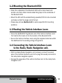
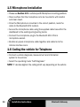
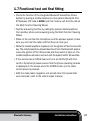
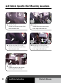
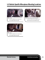
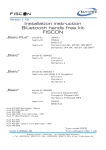
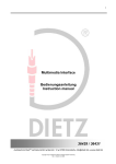
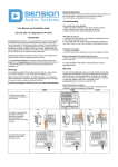
Audi
Installation Instructions
Version 1.1
Bluetooth Gateway M1000-C-BT1-AUD1
Kit Contents:
•Bluetooth ECU
•Microphone
•Vehicle Interface Loom
•Operating Manual
Tools/Ancillaries Required:
•Panel Removal tools
•Torx screwdriver
•Vehicle Diagnosis Computer, e.g. VAS 5052 or PC with VCDS VAG-COM software
•Double Sided fixing tape
Vehicle Requirement:
Installation can be carried out in vehicles with the following specification:
•Multi Function Steering Wheel & Driver Information Display (DIS) with
either of the following Audio systems: Chorus 2+, Concert 2+,
Concert 3, Symphony 2+, Symphony 3, RNS-E
OR
•Vehicles WITHOUT Multi Function Steering Wheel and Driver Information
Display (dis) with the following audio systems RNS-E
When fitted to vehicles WITHOUT Multi Function Steering Wheel and Multi
Function Display Plus (MFD+) the Phone System operation is limited to the
head unit controls.
Contents
Procedure:
02
1.1 General preparation of the vehicle for
installation of the components
03
1.2 Mounting the Bluetooth ECU
03
1.3 Routing the Vehicle Interface Loom
03
1.4 Connecting the Vehicle Interface Loom to the Radio/Radio Navigation unit.
03
1.5 Microphone Installation
04
1.6 Coding the vehicle for Telephone
04
1.7 Functional test and final fitting
07
1.8 Vehicle Specific ECU Mounting Locations
08
1.9 Vehicle Specific Microphone Mounting Locations
09
Procedure:
PLEASE NOTE:
•Installation of the Integrated Bluetooth Hands-free Phone System
should be carried out by a competent workshop. Special tools,
diagnostic equipment and special literature specific to the car is
required for fitting.
•Incorrect installation can result in damage to the vehicle or the
product.
•After completing the installation the car must be coded for operation
with the Bluetooth system using a diagnostics, measuring and
information system
•Secure all cables and harnesses so that they cannot come into
contact with any rotating or other moving parts and so that they
cannot chafe on any sharp metal or plastic edges.
1.1General preparation of the vehicle
for installation of the components
•Switch off the ignition and all electrical equipment
•Remove the radio/radio navigation system (refer to vehicle repair manual)
•Remove any existing hands-free phone system that is connected to
the CANBUS wiring and do not re-install it as it will conflict with the
Bluetooth Gateway system.
02
Installation Instructions
Bluetooth Gateway
1.2Mounting the Bluetooth ECU
•Clean the underside of the Bluetooth ECU with a clean towel and
alcohol, and then attach double sided fixing tape to the underside of
the Bluetooth ECU.
•Mount the ECU with the sockets facing upwards (if ECU is to be mounted
vertically) so that the plugs cannot fall out.
•Please see pictures Section 1.8 for vehicle specific ECU mounting
positions.
1.3Routing the Vehicle Interface Loom
•Route the QUADLOCK Plug/Socket end of the Vehicle Interface Loom
from behind the head unit to the location of the Bluetooth ECU.
•Secure the Vehicle Interface Loom using the supplied cable ties within
the dashboard to the existing wiring/wiring looms.
1.4Connecting the Vehicle Interface Loom
to the Radio/Radio Navigation unit.
•With the Radio/Radio Navigation unit removed, connect the socket
side of the Vehicle Interface Loom to the plug that usually connects to
the radio/radio navigation system.
•Connect the plug side of the vehicle interface loom to the radio/radio
navigation unit.
Bluetooth Gateway
Installation Instructions
03
1.5Microphone Installation
•Please see Section 1.9 for vehicle specific Microphone mounting positions.
•Clean surface that the microphone is to be mounted to with alcohol
and clean towel.
•Once the Microphone is mounted in the correct position, route the
cable to the Bluetooth ECU location.
•Secure the microphone cable using the supplied cable ties within the
dashboard to the existing wiring/wiring looms.
•Connect the microphone plug to the Bluetooth ECU 2.5mm
microphone socket.
•Bundle any spare microphone cable together and cable tie to the
Vehicle interface loom.
1.6Coding the vehicle for Telephone
•Connect a vehicle diagnosis, measurement and information
system to the vehicle.
•Select the operating mode “Self Diagnosis”
NOTE: ‘X’ denotes digits in the coding which vary depending on the vehicle
04
Installation Instructions
Bluetooth Gateway
Head Unit Coding
The following head units require coding, if not listed here they do not
need coding.
•RNS-E Head Unit
Address 56 (Radio)
0XXX?XX- Digit marked ? Has to be changed to 7
The RNS-E head unit need to have a software index of at least 350.
RNS-E RESET After coding you need to complete a RESET of the head unit.
Please turn the device off. When the head unit is turned back on keep
the ON/OFF button held down for 45 seconds until the head unit resets.
•Concert 2+, Symphony 2+
Address 56 (Radio)
0?XXXXX- Add 4 to the existing value of ? (e.g. 3 to 7)
•Concert 3, Symphony 3 – only for A4 8K, A5 8T, A5 8F, Q5 8R
Address 56 (Radio)
-Select Coding
-Select master
-Select Byte 3
-Change value of Byte 3 from 10000000 to 10000010
Address 47 (Sound system)
- only for A4 8K, A5 8T, A5 8F, Q5 8R with B&O sound system
-Select Byte 3
-Set Bit 0 to 1
-Set Bit 1 to 0
Bluetooth Gateway
Installation Instructions
05
Chassis Coding
•Chassis A4 8E and A6 4B
Address 17 (Instrument cluster)
Channel 62, add 2 to the existing value (e.g. 17 to 19)
•Chassis A4 8E
Address 16 (Steering Wheel)
02XXX– change 02XXX to 03XXX
•Chassis A6 4B and A8 4D
Address 16 (Steering wheel)
0XXX2– change 0XXX2 to 0XXX1
•Chassis A38P,TT8J,A48K,A58T,A58F,Q58R
Address 19 (CAN gateway)
- Select Address 19 – Diagnostic Interface Databus
- Select Coding
- Option 77 Telephone
- Set option 77 to coded.
06
Installation Instructions
Bluetooth Gateway
1.7Functional test and final fitting
•Check the function of the Integrated Bluetooth Hands-Free Phone
System by pairing a mobile telephone to the system (Bluetooth ID is
BT Gateway, PIN code is 1234) and then make a call. End the call via
the Multi Function Steering Wheel.
•Test the answering function by calling the paired mobile telephone
from another phone and answering using the Multi Function Steering
Wheel.
•While on the call test the microphone and the speaker system (make
sure you can hear the caller and that they can hear you)
•While the mobile telephone is paired, turn the ignition off and remove the
key. The mobile telephone should disconnect from the Bluetooth system.
Leave the ignition off for 30 seconds and then switch it back on. The
mobile telephone should re-connect with the system within 90 seconds.
•If the vehicle has an RNS-E head unit or is an A4/A5/Q5 with Concert3 or Symphony3 please ensure that the phone operating console
is displayed on the screen when the PHONE button (on the radio
control panel) is pressed.
•Refit the radio/radio navigation unit and all other trim panels that
were removed. (refer to the vehicle repair manual)
Bluetooth Gateway
Installation Instructions
07
1.8 Vehicle Specific ECU Mounting Locations
STEERING
COLUMN
1AA3 (8P), TT (8J)
Remove bolt behind trim panel & two
bolts underneath dash.
1BA3 (8P)
Location: Mounted to dash support
brace using double-sided tape.
STEERING
COLUMN
1CA4 (8K) A5 (8T & 8F) Q5 (8R)
Remove bolt behind trim panel & two
bolts underneath dash.
FUSE
BOX
FUSE
BOX
1DA4 (8K) A5 (8T & 8F) Q5 (8R)
Location: Mounted to dash support
brace using double-sided tape.
FUSE
BOX
1E A4(B7)
Location: Mounted to dash support
brace using double-sided tape.
08
Installation Instructions
Bluetooth Gateway
1.9 Vehicle Specific Microphone Mounting Locations
2AA3 (8P)
Location: Attached to trim panel with
wire routed behind trim panel.
2BA4 (8K) A5 (8T & 8F) Q5 (8R)
Location: Attached to steering column
shroud with wire routed behind vinyl.
2CA4(B7)
Location: Attached to trim panel with
wire routed behind trim panel.
Bluetooth Gateway
Installation Instructions
09