1
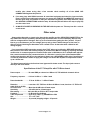
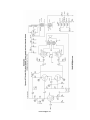
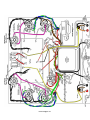
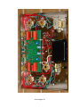
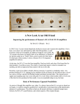
Dynaco ST-70 with VTA driver board Kit REBUILD assembly manual
In addition to the rebuild kit you will need in order to complete the ST-70 assembly
3 transformers (1 X PA-060 power transformer, 2 X A-470 output transformers)
* 1 VTA driver board and parts set
1 C-354 choke
4 X 1000 ohm resistors
the original 7 lug terminal strip
the dual .02 ceramic disk capacitor that was on lugs 5, 6 and 7 of the 7 lug terminal strip
2 grounding lugs
1 AC power cord
1 fuse post and fuse
1 rubber grommet
2 slide switches > 1 power switch, 1 stereo/mono switch
4 X EL34
* 3 X 12AT7
1 X GZ34 tubes
NOTE > Items marked with an asterisk are not found on an original ST-70
Optionally painting the transformers
You may, as an option, paint your transformers for a better appearance with some type of
heat resistant paint. Recommended, are any type of paint used to paint automobile engine
blocks (engine enamel) or paint used to paint barbecue grilles. To most people a semi-gloss
paint looks best on transformers. Use a spray can – don’t brush it on.
Recommended paints are Krylon BBQ and Stove paint (Krylon # 1618) OR any type of semigloss automobile engine enamel in a spray can. This is usually carried by Wal-Mart and many
other stores. Go to an auto supply store for engine enamel.
1. Obtain SIX 8 X 32 machine screws 2 ½ to 3 inches long with nuts.
2. Remove one transformer 8 X 32 nut, nylon spacer(s) and screw and replace it with one
of the six machine screws and nut. Tighten the nut securely.
3. Do the same for the transformer screw on the opposite diagonal corner of the
transformer.
4. Remove the other two 8 X 32 screws, nylon spacers and nuts on that transformer.
5. Repeat steps 2 through 4 for the other two transformers.
6. Sand any imperfections in the factory paint off the three transformers with 100 grit
paper. Sand again with 220 grit paper
7. Remove all sanding dust from the outer surface of the transformer.
8. Cover the transformer wires by placing them in a plastic bag. Use some masking tape
near the transformer to hold the bag on the wires.
9. Spray 3 light coats on each transformer and allow to dry overnight.
10. Remove the plastic bags that cover the wires
11. Reinstall all the original screws, spacers and nuts.
[email protected]
INSTRUCTIONS
NOTE – You may or may not want to construct the VTA driver board BEFORE or AFTER you attach the
chassis parts. If you wish to construct the VTA driver board at this time skip ahead to the VTA driver
board instructions which are inside the VTA package and proceed with its construction. When you are
through come back to this point and begin mounting the chassis parts.
Obtain the chassis. Remove the four stainless steel 6 X 32 screws. Taped inside the chassis are
four one inch round rubber “feet” which you may stick on the outside of the chassis bottom cover over
the four holes in the cover. Orient the chassis with the power transformer cutout facing you and mark
“V1”, “V2”, “V3”, “V6” and “V7” with a felt tip marker on the inside of the chassis next to the
appropriate tube socket. The tube socket numbers are shown on the pictorial.
1. Mount the FIVE octal sockets that fit on the chassis TOP from the BOTTOM OF THE CHASSIS
with ¼ inch long 4-40 stainless steel screws and 4-40 kep nuts. Use the pictorial to orient the
keyway of each tube properly. On V2, V3, V6 and V7 mount a GROUND LUG around the outside
screw closest to the side of the chassis and face this ground lug towards pin 8. Tighten all nuts
securely. DO NOT MOUNT the two front power take off tube sockets at this time.
2. Disassemble the two gold plated speaker binding posts from the mounting plates. Attach the
LEFT and RIGHT mounting plates to the back INSIDE of the amp with 4-40 hardware.
Reassemble the speaker binding posts on to the mounting plates. One of the black spacers with
rounded edges goes INSIDE the chassis and the other black spacer goes OUTSIDE the chassis.
Make sure that the BLACK terminal is on the side that says “G” on the outside of the chassis
frame. Tighten the two studs with the gold plated nuts provided.
3. Mount your rubber grommet in the 3/8 inch hole in the back CENTER of the chassis.
4. Mount the fuse holder in the "D” shaped hole in the back of the chassis. Tighten the nut but do
not over tighten as this may cause the plastic threads to break. Check and make sure that your
3 amp SLO-BLO fuse is inside the fuse holder.
5. Mount the SPST on/off switch on the REAR of the chassis with 4-40 hardware. Make sure that
the two terminals on this switch are close to the UNDERSIDE OF THE CHASSIS TOP SURFACE.
Check the pictorial.
6. Mount the power transformer in the large center cut out. The wires should face the FRONT of the
chassis. Fasten the power transformer to the chassis with four 8-32 kep nuts. In the original amp
a cable clamp was used on each of the two front bolts as seen in the pictorial. These clamps are
not really needed since, once soldered, the wires will stay in place. If you have your original
clamps use them.
7. Mount your C-354 choke on the RIGHT side of the chassis with two 8-32 screws and matching
kep nuts. Make sure that the two choke leads face towards the FRONT of the chassis.
8. Remove all components from lugs 1 through 4 of the 7 lug terminal strip and mount your SEVEN
lug terminal strip on the LEFT side of the chassis with two 4-40 screws and kep nuts as shown
on the pictorial.
9. Mount the TWO A-470 output transformers with 8-32 hardware. The side of the transformer with
the YELLOW-ORANGE-BROWN-BLACK leads must face the BACK of the amp. NOTE – If you are
reusing older original A-470 transformers mount the transformer with the LONGER RED LEAD
on the LEFT side.
[email protected]
10. Mount the quadruple section filter capacitor in the special cutout. It is IMPORTANT that the quad
cap be properly oriented. The 80 Mfd SECTION which is designated with a HALF CIRCLE must
face the BACK of the amp. Fasten by twisting each of the four mounting tabs one-quarter turn.
11. Mount your two grounding lugs in the hole just to the left of the quad cap. Mount them at a
slight angle as seen in the pictorial. Note - The color photo shows a one lug terminal strip
grounding point instead of the two grounding lugs.
12. NOTE – At this time DO NOT MOUNT the two front power takeoff sockets, the front slide switch
which fits into the stereo/mono slot or the input jacks. These three items must be mounted after
installation of the VTA driver board.
WIRING – Each length of hookup wire specified should have approximately ¼ inch of
insulation stripped from each end unless otherwise specified. Wires from the three
transformers should be shortened appropriately to the correct length to reach their terminal
point. As with the original Dynaco manual, if you see the symbol “(S)” this means to solder
that connection at that time. If the symbol is not there DO NOT SOLDER that connection at
that time. 20 gauge solid core copper wire is the recommended wire to use and need not be
pretinned with solder. If 20 gauge stranded wire is used the stripped leads should be
pretinned with solder. Only rosin core solder is recommended for soldering. Always make a
solid mechanical connection with your pliers to the terminal point before soldering. Always
keep the chassis and transformers on a soft surface like a towel so they won’t get scratched.
Orient the chassis so that the power transformer is towards you. Oriented this way, the LEFT
channel is on your LEFT and the RIGHT channel is on your RIGHT.
1. Twist the pair of WHITE leads from the power transformer together and dress to socket V1.
Connect one lead to pin #2 of V1 (S) and one lead to pin #8 of V1.
2. Twist the pair of RED leads from the power transformer together and dress to socket V1. Connect
one lead to pin # 4 of V1 (S). Connect the other lead to pin # 6 of V1 (S)
3. Twist the pair of GREEN leads from the power transformer together and dress to socket V2.
Connect one green lead to pin # 2 of V2 and one green lead to pin # 7 of V2.
4. Twist the pair of BROWN leads from the power transformer together and dress to socket V7.
Connect one brown lead to pin #2 of V7 and the other brown lead to pin #7 of V7.
5. Twist the BROWN/YELLOW and GREEN/YELLOW wires from the power transformer and dress to
the 7 lug terminal strip. Connect the BROWN/YELLOW lead to lug # 7 - the lug closest to the
power transformer. Connect the GREEN/YELLOW wire to lug # 5.
6. Connect the RED/YELLOW lead to one of the grounding lugs next to the quad cap filter capacitor.
7. Dress the RED lead from the LEFT OUTPUT TRANSFORMER and the RED lead from the RIGHT
OUTPUT TRANSFORMER to the 80 Mfd terminal on the QUAD CAP having the HALF-CIRCLE
symbol. This is the terminal that faces the REAR of the amp.
8. Twist together the two CHOKE leads. Connect one choke lead to 80 Mfd terminal on the quad cap
having the HALF-CIRCLE symbol and the other choke lead to the 40 Mfd terminal on the quad cap
having the SQUARE symbol.
9. Dress the two BLACK leads from the power transformer around the power transformer as shown
in the pictorial. Connect one BLACK lead to lug A of the fuse post (S) and one BLACK lead to lug
# 1 of the on/off switch (S).
[email protected]
10. Connect the BLACK lead from the RIGHT OUTPUT TRANSFORMER to the RIGHT BLACK speaker
terminal. Connect one end of a wire to the right BLACK speaker terminal (S). Connect the other
end of this wire to one of the grounding lugs next to the quad cap. Do EITHER A or B below.
A. If you are using 8 ohm speakers in your system then connect the ORANGE wire from the
right output transformer to the RIGHT RED speaker post (S). Now coil up the BROWN (4
ohm) wire. Place a small piece of tape over the end of this wire so it won’t short out to
the chassis.
B. If you are using 4 ohm speakers in your system then connect the BROWN wire from the
right output transformer to the RIGHT RED speaker post (S). Now coil up the ORANGE (8
ohm) wire. Place a small piece of tape over the end of this wire so it won’t short out to
the chassis.
* The remaining YELLOW wire from the transformer will be connected at a later step in
construction.
11. Repeat step 10 above for the LEFT OUTPUT TRANSFORMER and the LEFT speaker terminal.
12. Connect the BLUE wire from the LEFT OUTPUT TRANSFORMER to pin 3 of V3.(S) Connect the
BLUE/WHITE wire from the LEFT OUTPUT TRANSFORMER to pin 3 of V2.(S) Connect the BLUE
wire from the RIGHT OUTPUT TRANSFORMER to pin 3 of V6. (S) Connect the BLUE/WHITE wire
from the RIGHT OUTPUT TRANSFORMER to pin 3 of V7. (S)
13. Connect the GREEN wire from the LEFT OUTPUT TRANSFORMER to pin 4 of V3.(S) Connect the
GREEN/WHITE wire from the LEFT OUTPUT TRANSFORMER to pin 4 of V2.(S) Connect the
GREEN wire from the RIGHT OUTPUT TRANSFORMER to pin 4 of V6. (S) Connect the
GREEN/WHITE wire from the RIGHT OUTPUT TRANSFORMER to pin 4 of V7. (S)
14. Connect one end of the Dynaco dual .02 Mfd capacitor to lug #7 of the seven lug terminal strip (S).
Connect the middle wire of this capacitor to lug #6 of this terminal strip. Connect the remaining
end of this .02 Mfd capacitor to lug #5 of the seven lug terminal strip (S). Connect one end of a
wire from lug #6 of this terminal strip (S). Connect the other end of this wire to one of the
grounding tabs next to the quad cap. NOTE – Two separate .02 Mfd @ 100 volts or higher
capacitors may be used in place of this dual .02 Mfd cap. One capacitor across lugs 5 and 6 and
one across lugs 6 and 7.
15. Twist together a pair of 6 inch wires except for 1 ½ inches on each end. Connect one end of one
wire to pin #2 of V7 (S) Connect the other wire to pin #7 of V7 (S). Connect one of the other ends to
pin #2 of V6. Connect the remaining end to pin #7 of V6. Try to keep these twisted wires close to
the side of the chassis.
16. Twist together a 9 1/2 inch pair of wires except for 1 ½ inches on each end. Connect one end of
one wire to pin #2 of V6 (S). Connect the other wire to pin #7 of V6 (S). Route the other ends of
these two wires around the front right corner of the amp and along the front face of the amp.
These two free ends will be connected at a later step.
17. Twist together a pair of 6 inch wires except for 1 ½ inches on each end. Connect one end of one
wire to pin #2 of V2 (S) Connect the other wire to pin #7 of V2 (S). Connect one of the other ends to
pin #2 of V3. Connect the remaining end to pin #7 of V3. Try to keep these twisted wires close to
the side of the chassis.
18. Twist together a 9 1/2 inch pair of wires except for 1 ½ inches on each end. Connect one end of
one wire to pin #2 of V3 (S). Connect the other wire to pin #7 of V3 (S). Route the other ends of
these two wires around the front left corner of the amp and along the front face of the amp. These
two free ends will be connected at a later step.
[email protected]
19. Connect one end of a 5 ½ inch wire from lug 8 of V1 (S). Connect the other end of this wire to the
quad cap filter capacitor 40 Mfd lug having the SQUARE symbol (S)
20. Connect one end of a short 2 inch jumper wire from the 80 mfd lug on the quad cap filter capacitor
having the HALF-CIRCLE symbol (S). Connect the other end of this jumper wire to the 20 Mfd filter
capacitor terminal furthest to the RIGHT. NOTE – this filter capacitor lug has NO SYMBOL.
21. Connect one end of a 2200 ohm (2.2 K ohm – in with the VTA parts) from the 20 Mfd lug with NO
SYMBOL (S). Connect the other end of this resistor to the remaining 30 Mfd lug on the quad cap
filter capacitor with a TRIANGLE symbol that faces the front of the amp.
22. Connect one end of a 5 inch wire to the quad cap filter capacitor 30 Mfd lug with the TRIANGLE
symbol and have the other free end face the PCB cut out (S). The other free end of this wire will be
connected at a later step.
23. Connect one end of a short 2 or 3 inch wire from any of the quad cap TWIST TABS that have a
hole in them (S). Connect the other end of this wire to one of the grounding lugs next to the quad
cap.
24. Connect one end of a 5 inch wire to one of the grounding lugs next to the quad cap and have the
FREE END of this wire face the PCB cutout. Solder all 6 connections on the two grounding lugs.
(S) When you solder the connections on these two grounding lugs count to make sure that you
have SIX wires connected to these two lugs. You should have the following wires connected here.
It doesn’t matter which wire is connected to which grounding lug.
A. The RED-YELLOW wire from the power transformer
B. A wire from the LEFT BLACK speaker terminal
C. A wire from the RIGHT BLACK speaker terminal
D. A wire coming from lug #2 of the seven lug terminal strip
E. A wire connected to one of the grounding twist tabs of the quad cap
F. A 5 inch wire with one end free (The other end of this 5 inch wire will be connected in a later
step). It is important that these two grounding tabs be soldered properly as this is the main
grounding point for the entire amp.
25. Connect one end of a 1000 ohm 1 watt resistor to pin #5 of V3 (S). Connect the other end to pin #6
of V3. Keep the leads to this resistor and the next three resistors in this step at 3/8 of an inch or
less. Connect one end of a 1000 ohm 1 watt resistor to pin #5 of V2 (S). Connect the other end to
pin #6 of V2. Connect one end of a 1000 ohm 1 watt resistor to pin #5 of V6 (S). Connect the other
end to pin #6 of V6. Connect one end of a 1000 ohm 1 watt resistor to pin #5 of V7 (S). Connect the
other end to pin #6 of V7.
26. Obtain the last two tube sockets that will be installed in the two power take off holes in the front of
the chassis. DO NOT INSTALL THEM AT THIS TIME. Hold the socket with the back facing you and
the keyway pointing to the LEFT. Connect a 6 inch wire to pin #8 (S) of one of the sockets and run
the wire to the LEFT of the socket as viewed from the BACK of the socket. Connect a 9 inch wire
to pin #4 (S) of this socket and run this wire to the LEFT also. Place this socket with the two wires
attached aside. This will be installed in the LEFT power takeoff socket later.
27. Repeat step 29 for the other remaining tube socket (the keyway again faces to the LEFT as viewed
from the back) except run the wires to the RIGHT. This socket will become the RIGHT power take
off socket. Neither of these two sockets will be used for any “power take off” but two pins on each
tube socket will be used to measure bias on the four output tubes.
[email protected]
Installation of the VTA driver board
If you have not as yet built the VTA driver board please do so now and when completed come back
to this point in your instruction manual. The instructions for building the VTA driver board are with
the board.
1. Obtain the hardware set for the VTA driver board and locate the four 4-40 5/8 inch long stainless
steel screws. Place the four screws in from the TOP of the chassis. Place a 4-40 NON KEP nut
on the other end from the inside of the chassis and screw it down to the bottom of the inside of
the chassis but DO NOT TIGHTEN THE SCREW. Make a “test fit” of the driver board. If it won’t fit
on the screw ends then move the screws around slightly until the board fits properly. Tighten
the 4-40 nut firmly into position. Now place ANOTHER 4-40 NON KEP nut on top of the first nut
and tighten this nut on top of the first nut. The purpose of the TWO NUTS is to space the VTA
board down slightly into the chassis so the 4 outboard 270K resistors do not touch the chassis.
Make a final test fit and then remove the board.
2. Solder one end of FOUR 1 ¾ inch wires onto the board into the four input eyelets in the center
front of the board. The two UNMARKED holes nearest the edge of the board are GROUND
connectors. (S) The other two connectors are marked “R-IN” and “L-IN”. (S) After soldering all
four wires to the board bend the 4 wires slightly towards the center of the board to facilitate the
installation of the board. NOTE: If you have Russian PIO coupling caps on your driver board it is
easier NOW to connect ONE END of four 3 ½ inch wires (shorten them to the correct length
later) to the four UNMARKED HOLES AT THE TWO SIDES of the driver board that are about 7/8”
in from the front and back of the board. CONNECT THEM to THE BOTTOM OF THE DRIVER
BOARD and solder them in on the BOTTOM of the driver board. These are the four wires listed
in steps 5 and 6 under the section “Connections to the VTA Driver Board” on the next 2 pages.
3. Slide the VTA board onto the 4 screws until it bottoms out on the doubled up nuts. The four
input wires you just soldered should be FACING THE FRONT of the amp. Tighten down the
board this time WITH four 4-40 KEP nuts. Make sure that the two pair of twisted wires from V3
and V6 do not get caught under the board and are BEHIND the two front 5/8 inch screws that
hold the board. NOTE - The pictorial shows these twisted wires above the front power takeoff
sockets but they should run BELOW the two power take off sockets as viewed from the
underside. The color photograph shows the correct routing of these wires.
4. Obtain the two tube sockets that will fit into the power take off holes in the front of the chassis.
Bend the tube socket pins in against the back of the tube socket slightly. Bend towards the
BACK of the amp slightly the two front .22 Mfd orange drop coupling capacitors (or Russian PIO
capacitors) on the driver board to gain some clearance. Install the LEFT power takeoff socket
with 4-40 hardware. Install the RIGHT power take off socket with 4-40 hardware. Both are a tight
fit but will go in to their respective holes.
5. Install the slide switch that fits into the stereo/mono slot with 4-40 hardware. This switch will
NOT BE USED and NOT CONNECTED to the ST-70 circuitry in any way but it fills the front
rectangular slot to give the front face of the amp a better appearance.
6. Assemble the input terminals onto the input board. Place the input jack in from one side. Next,
place the ground tab, then a washer and then the nut from the other side of the input board.
Tighten the nut securely keeping the ground tabs to the bottom or side. Bend the ground tabs
out slightly at a 45 degree angle to make the electrical connections that will come later easier.
Install the input board with the input terminals from the INSIDE with the 4-40 hardware provided.
[email protected]
7. Remove 5/8 inch of insulation from the wire coming from pin #8 of the LEFT power takeoff. Run
this wire to V3. Slide the wire through pin # 1 (S) and into pin #8. You may have to twist either or
both pins slightly to line up the solder attachment holes. Attach one end of a 10 ohm bias
resistor (the four 10 ohm bias resistors are in with the VTA parts) to pin #8 of V3 (S). Connect
the other end of this resistor to the ground lug facing pin 8. (S)
8. Remove 5/8 inch of insulation from the wire coming from pin #4 of the LEFT power takeoff. Run
this wire to V2. Slide the wire through pin # 1 (S) and into pin #8. You may have to twist either or
both pins slightly to line up the solder attachment holes. Attach one end of a 10 ohm bias
resistor to pin #8 of V2 (S). Connect the other end of this resistor to the ground lug facing pin 8.
(S)
9. Remove 5/8 inch of insulation from the wire coming from pin #8 of the RIGHT power takeoff. Run
this wire to V6. Slide the wire through pin # 1 (S) and into pin #8. You may have to twist either or
both pins slightly to line up the solder attachment holes. Attach one end of a 10 ohm bias
resistor to pin #8 of V6 (S). Connect the other end of this resistor to the ground lug facing pin 8.
(S)
10. Remove 5/8 inch of insulation from the wire coming from pin #4 of the RIGHT power takeoff. Run
this wire to V7. Slide the wire through pin # 1 (S) and into pin #8. You may have to twist either or
both pins slightly to line up the solder attachment holes. Attach one end of a 10 ohm bias
resistor to pin #8 of V7 (S). Connect the other end of this resistor to the ground lug facing pin 8.
(S)
Connections to the VTA driver board
You will be making SEVENTEEN connections during the wiring to the VTA driver board
1. Connect the two input ground wires from the UNMARKED eyelets (these are two of the four
wires that you soldered in place in step 2 above) CLOSEST TO THE EDGE OF THE BOARD in the
center to the two grounding tabs on the input jacks. (S) Connect the wire coming from the “L-IN”
eyelet on the VTA board to the center tab of the LEFT input jack. (S) Connect the wire coming
from the “R-IN” eyelet on the VTA board to the center tab of the RIGHT input jack. (S)
2. Connect the two twisted pair of wires coming from V3 on the LEFT side of the amp to the two
open UNMARKED eyelets below the left tube socket on the bottom of the driver board. These
two UNMARKED eyelets are set at a about a 45 degree angle to each other. Shorten the wires to
the proper length (S)
3. Connect the two twisted pair of wires coming from V6 on the RIGHT side of the amp to the two
open UNMARKED eyelets below the right tube socket on the bottom of the driver board. These
two UNMARKED eyelets are set at a about a 45 degree angle to the sides of the board. Shorten
the wires to proper length (S)
4. If you have original Dynaco A-470 transformers then add about 12 inches of wire to each
YELLOW wire from each OUTPUT TRANSFORMER. (S). Insulate this connection. Shorten each
wire appropriately and connect the extended YELLOW wire from the LEFT OUTPUT
TRANSFORMER to the eyelet marked “NFB” on the LEFT side of the driver board. (S) Connect
the extended YELLOW wire from the RIGHT OUTPUT TRANSFORMER to the eyelet marked
“NFB” on the RIGHT side of the driver board. (S)
5. Connect a 2 ½ inch wire from pin #6 of V3 (S) to the UNMARKED eyelet near the left edge of the
driver board about 7/8 inch from the FRONT of the board. Do not press the wire in too deeply as
it may short against the chassis below. (S) Connect a 3 ½ inch wire from pin #6 of V2 (S) to the
[email protected]
UNMARKED eyelet near the left edge of the driver board about 7/8 inch from the BACK of the
board. Do not press the wire in too deeply as it may short against the chassis below. (S)
6. Connect a 2 ½ inch wire from pin #6 of V6 (S) to the UNMARKED eyelet near the right edge of the
driver board about 7/8 inch from the FRONT of the board. Do not press the wire in too deeply as
it may short against the chassis below. (S) Connect a 3 ½ inch wire from pin #6 of V7 (S) to the
UNMARKED eyelet near the right edge of the driver board about 7/8 inch from the BACK of the
board. Do not press the wire in too deeply as it may short against the chassis below. (S)
7. Connect the RED-BLACK wire from the power transformer to the eyelet on the board marked “50 VAC” near the back edge of the board. Do not press the wire in too deeply as it may short
against the chassis below. (S)
8. Connect the free end of the 5 inch wire coming from the grounding lugs to the eyelet marked
“GD” on the rear edge of the driver board. (S)
9. Connect the wire coming from the quad cap TRIANGLE terminal to the eyelet marked “B+” near
the center of the driver board. (S)
10. Route the AC cord through the rubber grommet on the rear face of the amp. Split the two wires
for about 6 inches and tie a knot in the two wires. Strip ¼ inch of insulation from each wire and
connect one wire to terminal “B” of the fuse post (S) and the other wire to terminal #2 of the
on/off switch. (S)
Initial startup
1. Make sure that the 3 amp SLO-BLO fuse is in the fuse holder.
2. Place the three 12AT7 tubes in the sockets on the top of the driver board. DO NOT PLUG IN THE
RECTIFIER TUBE OR THE EL34 OUTPUT TUBES at this time. Plug in the amp to an AC outlet
and turn on the amp. Wait about 20-30 seconds to see if the three 12AT7 tubes light up. If they
do and they stay on for a minute then proceed to step 3. If the 12AT7 tubes don’t light up or if
the fuse blows check the wiring below and measure the AC voltage where both sets of twisted
wires connect to the driver board. Check to see that you get about 5.9 - 6.5 volts AC ACROSS
THE TWO WIRES. If not, check the wiring back to the power transformer for an error.
3. Get your multitester and set the range for 0 to 2 volts DC. CONNECT THE SPEAKERS. Place
the GZ34 rectifier tube and just the LEFT EL34 output tubes in their socket. Turn on the amp.
Allow the amp to warm up for a minute and check to see that the EL34 and GZ34 tubes light up
properly. Measure the bias on the LEFT output tubes by placing the BLACK NEGATIVE probe
anywhere on the chassis and the RED POSITIVE probe in the hole marked “Biaset 1.56 v”. With
a small screwdriver adjust the FRONT LEFT bias adjuster on the driver board closest to the front
left tube. Turn the adjuster CLOCKWISE TO REDUCE BIAS and COUNTERCLOCKWISE TO
INCREASE BIAS. Set the bias for .400 volts if you are using EL34. Now place the positive probe
in pin 4 (which is on the opposite side of the power take off socket) and use the BACK LEFT
bias adjuster to measure bias on the LEFT REAR output tube. Set it the same as the front tube.
Turn off the amp.
4. Plug in the two RIGHT channel EL34 tubes, turn on the amp and repeat the bias procedure as
outlined above on the RIGHT channel tubes. Now go back to the left channel tubes and notice
that the bias is now a little LOW. ADJUSTING BIAS ON ONE TUBE HAS A SLIGHT AFFECT ON
THE OTHERS. Go back and forth between all output tubes until all tubes have the proper bias.
5. If at any time a fuse blows IMMEDIATELY check carefully the power transformer wiring for an
error. Check all wiring against the pictorial. If a fuse blows AFTER A FEW SECONDS and/or the
[email protected]
rectifier tube shows arcing after a few seconds check carefully all of the QUAD CAP
CONNECTIONS against the pictorial.
6. If the amp plays with HUM disconnect all associated equipment and short the input terminals.
Plug in an RCA input cable and connect a wire across the POSITIVE and NEGATIVE terminals. If
the hum goes away, the problem is with your associated equipment. If the amp still hums, check
ALL GROUND CONNECTIONS inside the amp. A bad tube (that still allows the amp to play OK)
can also cause hum.
7. ALWAYS BE CAREFUL WORKING ON THE AMP with the power on. This amp has 400 + volts in
certain areas.
Other notes
Always adjust bias with no signal going through the amplifier and the SPEAKERS CONNECTED to the
amp. Without a load (the speakers), bias will jump around because of circuit instability. Bias will vary
with line voltage and tube changes. Don't try to be a fanatic about getting the bias "perfect" - Expect
bias to go up and down as your line voltage goes up and go down. Subtle changes in bias have no
effect on sound. Checking the bias about once a month is fine. As the tubes wear a little bias will
change slightly.
If you cannot bias ONE output tube properly then THAT tube may be defective. REPLACE that tube. If
two or three or ALL tubes will not bias properly or all tubes have NO bias voltage try replacing the GZ34
rectifier tube. A common symptom of a weak rectifier tube is LOW bias on all or multiple tubes with the
bias control turned all the way counterclockwise. If a 5U4 tube is used in place of the standard GZ34
rectifier tube then bias will have to be readjusted. Always use a GZ34/5AR4 rectifier tube if possible as it
is indirectly heated and is slower to apply full voltage. This allows the amplifier’s components to warm
up at a slower rate.
The Stereo/mono switch on the front has been bypassed for better sound. The input jacks connect
directly to the driver board.
Specifications of the ST-70 Amplifier with VTA Driver board
Power output . . . . . . …… 35 watts RMS per channel at 1 KHz at 1% THD with both channels driven
Frequency response . . . . 10 Hz to 30 KHz +/- .1 dB at 1 watt
Power bandwidth . . . . … 17 Hz to 30 KHz +/- .3 dB at 35 watts
Distortion . . . . . . ………. Less than .15% THD from 20 Hz to 20 KHz at 1 watt, less than 1 % THD at 35
watts 20 Hz to 20 KHz
Hum and noise . . . . . ….. More than 90 dB below 35 watt output
Sensitivity . . . . . . ………. 500 millivolts for 35 watt output
Bias setting …………… .400 volts DC per EL34 or KT77 output tube
Feedback ………………… 13 dB total loop feedback
Tube complement . . . . … (4) EL34 (3) 12AT7 (1) 5AR4/GZ34 or 5U4
Size . . . . . . . . …………. 13" x 9.5" x 6.5"
Weight ……………………. 30 pounds (shipping weight = 35 pounds
[email protected]
Voltage readings
* Note # 1 – Make sure you have your meter set to AC or DC as mentioned below. Ground is
any point on the chassis frame. Place the black or negative probe on the chassis and the red
or positive probe on the point mentioned. All tubes should be plugged in, inputs shorted or
connected to your preamp, speakers connected and no signal should be running through the
amplifier. Be careful not to cross two pins with the positive probe !
* Note # 2 – Readings very slightly above or very slightly below the range are not normally
a sign of a problem. Line voltages vary slightly throughout the country. Differences in the
GZ34 rectifier tube can cause variations also. The use of a solid state rectifier in place of the
GZ34 may cause some voltages to be higher.
GZ34 – Pin 2 to ground – 410 - 450 volts DC
Pin 8 to ground – 410 - 450 volts DC
Pin 4 to ground – 330 - 370 volts AC
Pin 6 to ground – 330 - 370 volts AC
Any EL34 – Pin 1 to ground – approx .400 volts DC (depends on bias setting)
Across pins 2 and 7 – 5.9 – 6.5 volts AC
Pin 3 to ground – 400 - 430 volts DC
Pin 4 to ground – 400 - 430 volts DC (2 or 3 volts higher than pin 3)
Pin 5 to ground – minus 30 to minus 38 volts DC
Pin 6 to ground – minus 30 to minus 38 volts DC
Pin 8 to ground – approx .400 volts DC (depends on bias setting)
Quad cap – Section # 1 (square symbol) –----- 410 – 440 volts DC
Section # 2 (half circle symbol) ---------- 400 – 430 volts DC
Section # 3 (NO symbol) ------------------- 400 – 430 volts DC
Section # 4 (triangle symbol) ------------ 380 – 420 volts DC
Central 12AT7 – Pin 1 or pin 6 to ground > 130 – 160 volts DC
Two outer 12AT7’s – Pin 1 or pin 6 to ground > 240 – 280 volts DC
Any 12AT7 – across the two incoming heater wires > 5.9 - 6.5 volts AC
“-50 VAC” on driver board > 48 – 55 volts AC
“B+” on driver board > 380 – 420 volts D
[email protected]
[email protected]
[email protected]
[email protected]