1
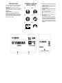
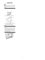
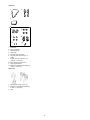
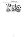
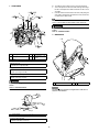
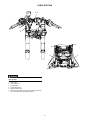
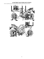
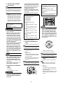
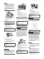
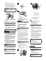
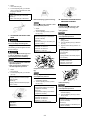
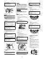
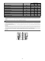
YZFR1Y(C)
ASSEMBLY MANUAL
LIT-11666-22-78
14B-28107-10
FOREWORD
This Assembly Manual contains the information required for the correct assembly of
this Yamaha vehicle prior to delivery to the
customer. Since some external parts of the
vehicle have been removed at the Yamaha
factory for the convenience of packing, assembly by the Yamaha dealer is required.
It should be noted that the assembled vehicle should be thoroughly cleaned, inspected, and adjusted prior to delivery to the
customer.
IMPORTANT
The service specifications given in this assembly manual are based on the model as
manufactured. Yamaha Motor Company,
Ltd. is continually striving to improve all of
its models. Modifications and significant
changes in specifications or procedures
will be forwarded to all authorized Yamaha
dealers and will appear in future editions of
this manual where applicable. The procedures below are described in the order that
the procedures are carried out correctly
and completely. Failure to do so can result
in poor performance and possible harm to
the vehicle and/or rider.
CONCERNING CRATE DAMAGE:
Follow the instructions in the Dealer Warranty Handbook, Procedure Section.
SYMBOLS USED IN THE
ASSEMBLY MANUAL
(1)
(2)
(3)
(4)
(5)
(6)
(7)
IMPORTANT MANUAL INFORMATION
Particularly important information is distinguished in this manual by the following notations.
This is the safety alert symbol. It is
used to alert you to potential personal
injury hazards. Obey all safety messages that follow this symbol to avoid
possible injury or death.
A WARNING indicates a hazardous
situation which, if not avoided, could
result in death or serious injury.
A NOTICE indicates special precautions that must be taken to avoid damage to the vehicle or other property.
A TIP provides key information to make
procedures easier or clearer.
YZFR1Y(C)
ASSEMBLY MANUAL
©2008 by Yamaha Motor Corporation, U.S.A.
First Edition, December 2008
All rights reserved.
Any reproduction or unauthorized use
without the written permission of
Yamaha Motor Corporation, U.S.A.
is expressly prohibited.
Printed in U.S.A.
P/N LIT-11666-22-78
(8)
In order to simplify descriptions in this assembly manual, the following symbols are
used:
(1): Coat with lithium-soap-based grease.
(2): Tighten to 10 Nm. (10 Nm = 1.0 m•kgf
= 7.2 ft•lbf)
(3): Towards the front of the vehicle
(4): Clearance required
(5): Install so that the arrow mark faces
upward.
(6): Apply motor oil.
(7): Made of rubber or plastics
(8):
A: Ref. No. (indicating the order of
operations.)
B: Part name
C: Quantity of parts per vehicle
D: Place where parts are held
V:
Stored in plastic bag
C:
Stored in carton box
S:
Fixed inside the steel frame
and/or contained in the Styrofoam tray (upper or lower)
*:
Temporarily installed or secured
E: Size or material of parts
d/D: Diameter of part
L:
Length of part
e.g., 5 (0.20) = 5 mm (0.20 in)
PREPARATION
To assemble the vehicle correctly, supplies
(e.g., oils, greases, and shop rags) and
sufficient working space are required.
Workshop
The workshop where the vehicle is assembled should be clean, spacious, and have a
level floor.
Self-protection
Protect your eyes with suitable safety
glasses or goggles when using compressed air, when grinding or when doing
any operation which may cause particles to
fly off. Protect hands and feet by wearing
safety gloves or shoes.
SYMBOLS USED ON
CRATE CARTON
(1)
(2)
(3)
(4)
(5)
(6)
(1) Contents of the transport package are
fragile, therefore the package must be
handled with care.
(2) Indicates correct upright position of the
transport package.
(3) Transport package must be kept away
from rain.
(4) Insertion of the forklift arms from this
side can cause damage.
(5) Do not step anywhere on this carton
box.
(6) Up to 6 of the transport packages can
be piled up.
(7) Lift arm insertion position
If the forklift arms cannot be inserted
under the transport package in alignment with the two yellow labels, adjust
the arms so that they are positioned
evenly in relation to these marks while
taking care not to damage the package
contents.
UNPACKING
1. Remove the frame cover (1).
To remove the frame cover, cut the plastic
bands around the cover using a cutter or
scissors.
2. Remove the bolts (2) and nut (3).
3. Remove the packing frames (4). (Lift
up and then move to the side.)
• Remove the bolts while holding the
frame.
• Before starting the assembly, check for
damaged or missing parts. Check both
the parts contained in the carton boxes
and on the vehicle for damage, scratches, and other defects.
-1-
PARTS LOCATION
1. Carton box
2. Plastic bag
-2-
Carton box
1
2
3
4
5
6
7
8
9
10
1.
2.
3.
4.
5.
6.
Windshield
Rear view mirrors
Owner's manual
Plastic bag
Dampers (rear view mirror)
Cap nuts (rear view mirror) [d = 6
(0.24)]
7. Collars (rear view mirror) [d = 6.5
(0.26), D = 10.5 (0.41)]
8. Mirror bases (rear view mirror)
9. Plugs (upper bracket)
10. Hexagon socket bolt (rider seat) [d = 6
(0.24), L = 23 (0.91)]
Plastic bag
1. Steering stem nut [d = 28 (1.10)]
2. Hexagon socket bolts (handlebar) [d =
6 (0.24), L = 25 (0.98)]
3. Keys
-3-
SETUP PROCEDURES
Perform the setup procedures in the order indicated by the numbers. Always follow the order as shown.
3
4
2 1
5
-4-
1. HANDLEBAR
2,B
113
3
2,B
1,A
3
13
B: To install the clutch cable, be sure to proceed as follows:
a. Turn in the adjuster on the lever holder until tight. Next, align
the slit in the adjuster and cable socket with the slit in the lever holder.
b. Insert the cable end into the lever hole. Next, while pulling the
outer cable in the direction opposite to the lever, seat the outer cable into the cable socket.
13
Check the clutch lever for smooth action.
Refer to "ADJUSTMENTS AND PREDELIVERY SERVICE".
Proper cable routing is essential to assure safe vehicle operation.
Refer to "CABLE ROUTING".
3. WINDSHIELD
1,A
C
16
C
1
Steering stem nut
1
V
2
Hexagon socket bolt
2
V
3
Plug
2
V
16
d = 28 (1.10)
d = 6 (0.24), L = 25
(0.98)
A: Tighten the steering stem nut to specification.
Steering stem nut
113 Nm (11.3 m•kgf, 82 ft•lbf)
B: Tighten the bolts to specification.
Bolt
13 Nm (1.3 m•kgf, 9.4 ft•lbf)
C: Tighten the bolts to specification.
Bolt
16 Nm (1.6 m•kgf, 11 ft•lbf)
1
Windshield
1
C
Proper cable routing is essential to assure safe vehicle operation.
Refer to "CABLE ROUTING".
A:
2. CLUTCH CABLE
The windshield is made of an acrylate resin. Take care so
that it is not scratched.
A
B
1
Clutch cable
1
1
*
A: Lubricate the pivoting part of the clutch lever.
Recommended lubricants
Yamaha cable lube or motor oil
-5-
4. REAR VIEW MIRRORS
5. BATTERY
4
4
5,C
7,E
7
11,F
5
7
7,E
7
3,B
2
2 1,A
10
4
4
B
3
7
7
6,D
C
3
2,A
1
2
3,B
2
1,A
3
2
4
8
9
1
5
1
Damper
2
V
2
Collar
4
V
3
4
5
Mirror base
Rear view mirror
Cap nut
2
2
4
V
C
V
d = 6.5 (0.26), D =
10.5 (0.41)
d = 6 (0.24)
A: Be sure to install the dampers between the rear view mirror
bracket and the windshield.
B: Install the mirror bases on both sides of the vehicle with the
one marked "L" facing outward on the left and the one
marked "R" facing outward on the right.
C: Tighten the nuts to specification.
1
2
3
Battery seat
Battery
Nut
1
1
2
*
*
*
4
Bolt
2
*
5
Battery cover
1
*
6
Hexagon socket bolt
2
*
7
Hexagon socket bolt
2
*
1
1
1
*
*
*
Hexagon socket bolt (left)
1
*
Hexagon socket bolt (right)
1
V
8 Owner's tool kit
9 Band
10 Rider seat
Nut
7 Nm (0.7 m•kgf, 5.1 ft•lbf)
11
d = 6 (0.24)
d = 6 (0.24), L = 10
(0.39)
d = 6 (0.24), L = 25
(0.98)
d = 6 (0.24), L = 20
(0.79)
d = 6 (0.24), L = 23
(0.91)
d = 6 (0.24), L = 23
(0.91)
A: Installing the battery.
Refer to "ADJUSTMENTS AND PREDELIVERY SERVICE".
B: First, connect the positive lead (red lead) to the positive terminal.
C: Second, connect the negative lead (black lead) to the negative terminal.
Refer to "CABLE ROUTING".
D: Tighten the bolts to specification.
Bolt
7 Nm (0.7 m•kgf, 5.1 ft•lbf)
E: Tighten the bolts to specification.
Bolt
7 Nm (0.7 m•kgf, 5.1 ft•lbf)
F: Tighten the bolts to specification.
Bolt
7 Nm (0.7 m•kgf, 5.1 ft•lbf)
-6-
CABLE ROUTING
1,A
3
2
5
Proper cable and lead routing are essential to insure safe vehicle operation.
1.
2.
3.
4.
5.
A.
Clutch cable
Front brake hose
Throttle cables
Positive battery lead
Negative battery lead
Route the clutch cable so as to get along the front side of the
main switch after passing it through the guide.
-7-
4
ADJUSTMENTS AND PREDELIVERY SERVICE
Perform the predelivery service in the order indicated by the letters. Always follow the order as shown.
O
P
K L
D
J
B
A
E L I J
J
I
B
M N M M
HG
C
-8-
J
F
A. CHECKING AND CHARGING
THE BATTERY
The battery used in this vehicle is a VRLA
(Valve Regulated Lead Acid) battery, it has
been pre-filled with electrolyte at the factory so there is no need to add fluid at any
time.
1. Check:
Using a digital volt meter, the state of a
discharged VRLA (Valve Regulated
Lead Acid) battery can be checked by
measuring open-circuit voltage (the
voltage measured with the positive and
negative terminals being disconnected).
Open-circuit voltage
12.8 V or higher
Charging time
Charging is not necessary
• Do not attempt boost charging under
any circumstances.
• Battery electrolyte is poisonous and
dangerous, causing severe burns,
etc. It contains sulfuric acid. Avoid
contact with skin, eyes or clothing.
Antidote: External -Flush with water.
Internal-Drink large quantities of water or milk. Follow with milk of magnesia, beaten egg, or vegetable oil. Call
physician immediately.
Eyes: Flush with water for 15 minutes
and get prompt medical attention.
Batteries produce explosive gases.
Keep sparks, flame, cigarettes, etc.,
away. Ventilate when charging or using in enclosed space. Always shield
eyes when working near batteries.
KEEP OUT OF THE REACH OF CHILDREN.
• If the voltage is lower than 12.8 V the
battery must be charged. If this is not
done, the life of the battery will be
shortened drastically. Refer to the
service manual for battery charging
instructions.
• Never remove the strip of caps, nor
add any water or electrolyte.
• The tire pressure and the suspension
must be adjusted according to the total weight (including cargo, rider, passenger, and accessories) and the
anticipated riding speed.
• Operation of an overloaded vehicle
could cause tire damage, an accident,
or an injury.
NEVER OVERLOAD THE VEHICLE.
Basic weight:
With oil and full fuel tank
206 kg (454 lb)
Maximum load*
189 kg (417 lb)
Cold tire pressure
Up to 90 kg (198 lb) load*
Front
250 kPa (2.50 kgf/cm2, 36 psi)
Rear
290 kPa (2.90 kgf/cm2, 42 psi)
90 kg (198 lb)–Maximum load*
Front
250 kPa (2.50 kgf/cm2, 36 psi)
Rear
290 kPa (2.90 kgf/cm2, 42 psi)
High speed riding
Front
250 kPa (2.50 kgf/cm2, 36 psi)
Rear
290 kPa (2.90 kgf/cm2, 42 psi)
* Load is the total weight of cargo, rider,
passenger and accessories.
Recommended engine oil type
YAMALUBE 4 (10W-40) or SAE 10W40, YAMALUBE 4 (20W-50) or SAE
20W-50
Recommended engine oil grade
API service SG type or higher, JASO
standard MA
Quantity
Without oil filter cartridge replacement
3.73 L (3.94 US qt, 3.28 Imp. qt)
• Engine oil also lubricates the clutch
and the wrong oil types or additives
could cause clutch slippage. Therefore, do not add any chemical additives or use engine oils with a grade of
CD (c) or higher and do not use oils labeled "ENERGY CONSERVING II" (d).
• Do not allow foreign materials to enter
the crankcase.
c
C. CHECKING THE ENGINE OIL
LEVEL
1. Stand the vehicle on a level surface.
4
d
• Place the vehicle on a suitable stand.
• Make sure that the vehicle is upright.
2. Let the engine idle for a few minutes,
and then turn it off.
3. Check:
• engine oil level
The engine oil level should be between
the minimum level mark (a) and maximum level mark (b).
Below the minimum level mark → Add
the recommended engine oil to the
proper level.
4. Start the engine, warm it up for several
minutes, and then turn it off.
5. Check the engine oil level again.
Before checking the engine oil level, wait a
few minutes until the oil has settled.
• Place the vehicle on a suitable stand.
• Make sure that the vehicle is upright.
B. MEASURING THE TIRE PRESSURE
1. Measure:
• tire pressure
Out of specification → Adjust.
b
a
• The tire pressure should only be
checked and regulated when the tire
temperature equals the ambient air
temperature.
-9-
Before checking the engine oil level, wait a
few minutes until the oil has settled.
D. CHECKING THE COOLANT
LEVEL
1. Stand the vehicle on a level surface.
2. Check:
• coolant level
The coolant level should be between
the minimum level mark (a) and maximum level mark (b).
Below the minimum level mark → Add
the recommended coolant to the proper level.
• Adding water instead of coolant lowers the antifreeze content of the coolant. If water is used instead of
coolant, check and correct the antifreeze concentration of the coolant.
• Use only distilled water. Soft water
may be used if distilled water is not
available.
1
a
b
a
F. ADJUSTING THE FRONT
BRAKE
1. Adjust:
• brake lever position
(distance (a) from the throttle grip to
the brake lever)
a. While pushing the brake lever forward,
turn the adjusting knob (1) until the
brake lever is in the desired position.
b
a
3. Start the engine, warm it up for several
minutes, and then turn it off.
4. Check:
• coolant level
Before checking the coolant level, wait a
few minutes until it settles.
E. ADJUSTING THE THROTTLE
CABLE FREE PLAY
1. Measure:
• throttle cable free play (a)
Out of specification → Adjust.
Throttle cable free play (at the flange of
the throttle grip)
3–5 mm (0.12–0.20 in)
a
2.
a.
b.
c.
2 3
1
Adjust:
Slide back the rubber covers (1).
Loosen the locknut (2).
Turn the adjusting nut (3) in direction
(a) or (b) until the specified throttle cable free play is obtained.
Direction (a)
Throttle cable free play is increased.
Direction (b)
Throttle cable free play is decreased.
d. Tighten the locknut.
e. Slide the rubber covers to their original
position.
After adjusting the throttle cable free
play, turn the handlebar to the right and
to the left to ensure that this does not
cause the engine idling speed to
change.
Be sure to align the setting on the adjusting
knob with the arrow mark (2) on the brake
lever.
Direction (b)
Distance (a) is increased.
Direction (c)
Distance (a) is decreased.
2. Adjust:
• brake pedal position
a. Loosen the locknut (1).
b. Turn the adjusting bolt (2) in direction
(a) or (b) until the specified brake pedal
position is obtained.
Direction (a)
Brake pedal is raised.
Direction (b)
Brake pedal is lowered.
After adjusting the brake pedal position,
make sure that the end of the adjusting
bolt (c) is visible through the hole (d).
After adjusting the brake lever position,
make sure that there is no brake drag.
A soft or spongy feeling in the brake lever can indicate the presence of air in
the brake system. Before the vehicle is
operated, the air must be removed by
bleeding the brake system. Air in the
brake system will considerably reduce
braking performance and could result in
loss of control and possibly an accident. Therefore, check the brake system
and bleed if necessary.
1
c. Tighten the locknut to specification.
Locknut
16 Nm (1.6 m•kgf, 11 ft•lbf)
A soft or spongy feeling in the brake
pedal can indicate the presence of air in
the brake system. Before the vehicle is
operated, the air must be removed by
bleeding the brake system. Air in the
brake system will considerably reduce
braking performance and could result in
loss of control and possibly an accident. Therefore, check the brake system
and bleed if necessary.
a
b
2
After adjusting the brake pedal position,
make sure that there is no brake drag.
c
G. ADJUSTING THE REAR BRAKE
1. Measure:
• brake pedal position
(distance (a) from the center of the
footrest bracket bolt to the center of the
brake pedal)
Out of specification → Adjust.
Brake pedal position (below the center of
the footrest bracket bolt)
12–18 mm (0.47–0.71 in)
-10-
H. ADJUSTING THE REAR BRAKE
LIGHT SWITCH
• The rear brake light switch is operated by
the movement of the brake pedal.
• The rear brake light switch is properly adjusted when the brake light comes on just
before the braking effect starts.
1. Check:
• rear brake light operation timing
Incorrect → Adjust.
2. Adjust:
• rear brake light operation timing
a. Hold the main body (1) of the rear
brake light switch so that it does not rotate and turn the adjusting nut (2) in direction (a) or (b) until the rear brake
light comes on at the proper time.
2
a
1
Direction (a)
Brake light comes on sooner.
Direction (b)
Brake light comes on later.
1
a
2
a
b
A.
B.
I.
CHECKING THE BRAKE FLUID
LEVEL
Front brake
Rear brake
J. BLEEDING THE HYDRAULIC
BRAKE SYSTEM
1. Stand the vehicle on a level surface.
• Place the vehicle on a suitable stand.
• Make sure that the vehicle is upright.
2. Check:
• brake fluid level
Below the minimum level mark (a) →
Add the recommended brake fluid to
the proper level.
Recommended brake fluid
DOT 4
• Use only designated brake fluid. Other brake fluids may cause the rubber
seals to deteriorate, causing leakage
and poor brake performance.
• Refill with the same type of brake fluid
that is already in the system. Mixing
brake fluids may result in a harmful
chemical reaction, leading to poor
brake performance.
• When refilling, be careful that water
does not enter the reservoir. Water
will significantly lower the boiling
point of the brake fluid and could
cause vapor lock.
Brake fluid may damage painted surfaces and plastic parts. Therefore, always
clean up any split brake fluid immediately.
Bleed the hydraulic brake system whenever:
• the system was disassembled,
• a brake hose was loosened or removed,
• the brake fluid level is very low,
• brake operation is faulty.
• Be careful not to spill any brake fluid or
allow the brake fluid reservoir to overflow.
• When bleeding the hydraulic brake system, make sure that there is always
enough brake fluid before applying the
brake. Ignoring this precaution could allow air to enter the hydraulic brake system, considerably lengthening the
bleeding procedure.
• If bleeding is difficult, it may be necessary to let the brake fluid settle for a few
hours. Repeat the bleeding procedure
when the tiny bubbles in the hose have
disappeared.
1. Bleed:
• hydraulic brake system
a. Add the recommended brake fluid to
the proper level.
b. Install the brake fluid reservoir diaphragm.
c. Connect a clear plastic hose (1) tightly
to the bleed screw (2).
2
1
In order to ensure a correct reading of the
brake fluid level, make sure that the top of
the reservoir is level.
A.
B.
C.
Front brake master cylinder
Front brake caliper
Rear brake caliper
The bleeding order of the front hydraulic
brake system is the following:
• Front brake master cylinder
• Front brake calipers
• Front brake master cylinder
d. Place the other end of the hose into a
container.
e. Slowly apply the brake several times.
f. Fully squeeze the brake lever or fully
depress the brake pedal and hold it in
position.
g. Loosen the bleed screw. This will release the tension and cause the brake
lever to contact the throttle grip or the
brake pedal to fully extend.
h. Tighten the bleed screw and then release the brake lever or brake pedal.
i. Repeat steps (e) to (h) until all of the air
bubbles have disappeared from the
brake fluid in the plastic hose.
j. Tighten the bleed screw to specification.
Bleed screw
Brake caliper
5 Nm (0.5 m•kgf, 3.6 ft•lbf)
Brake master cylinder
6 Nm (0.6 m•kgf, 4.3 ft•lbf)
k. Fill the reservoir to the proper level.
Refer to "CHECKING THE BRAKE
FLUID LEVEL".
After bleeding the hydraulic brake system, check the brake operation.
K. ADJUSTING THE CLUTCH CABLE FREE PLAY
1. Measure:
• clutch cable free play (a)
Out of specification → Adjust.
Clutch cable free play (at the end of the
clutch lever)
10–15 mm (0.39–0.59 in)
-11-
2. Adjust:
• clutch cable free play
a. Turn the adjusting bolt (1) in direction
(b) or (c) until the specified clutch cable
free play is obtained.
1
a
b
Direction (b)
Clutch cable free play is increased.
Direction (c)
Clutch cable free play is decreased.
Rebound damping (right front fork leg)
Never go beyond the maximum or minimum adjustment positions.
1. Adjust:
• rebound damping
a. Turn the adjusting screw (1) in direction (a) or (b).
L. ADJUSTING THE FRONT FORK
LEGS
Securely support the vehicle so that
there is no danger of it falling over.
Spring preload
The following procedure applies to both of
the front fork legs.
Always adjust both front fork legs evenly. Uneven adjustment can result in
poor handling and loss of stability.
Direction (a)
Rebound damping is increased (suspension is harder).
Direction (b)
Rebound damping is decreased (suspension is softer).
Adjusting positions
Standard: 12 clicks out*
Minimum: 25 clicks out*
Maximum: 1 click out*
*: from the fully turned-in position
b
1
• Grooves are provided to indicate the
adjustment position.
• Never go beyond the maximum or
minimum adjustment positions.
Direction (a)
Spring preload is increased (suspension is harder).
Direction (b)
Spring preload is decreased (suspension is softer).
1
a
b
Adjusting positions
Standard: 2
Minimum: 0
Maximum: 5
Securely support the vehicle so that
there is no danger of it falling over.
Spring preload
Never go beyond the maximum or minimum adjustment positions.
1. Adjust:
• spring preload
a. Turn the adjusting bolt (1) in direction
(a) or (b).
b. Align the match mark (3) with the " △ "
mark (2).
Direction (a)
Spring preload is increased (suspension is harder).
Direction (b)
Spring preload is decreased (suspension is softer).
Adjusting positions
Standard: 8 turns out*
Minimum: 16 turns out*
Maximum: 0 turn out*
*: from the fully turned-in position
a
1. Adjust:
• spring preload
a. Turn the adjusting bolt (1) in direction
(a) or (b).
M. ADJUSTING THE REAR SHOCK
ABSORBER ASSEMBLY
Compression damping (left front fork
leg)
Never go beyond the maximum or minimum adjustment positions.
1. Adjust:
• compression damping
a. Turn the adjusting screw (1) in direction (a) or (b).
Direction (a)
Compression damping is increased
(suspension is harder).
Direction (b)
Compression damping is decreased
(suspension is softer).
Adjusting positions
Standard: 20 clicks out*
Minimum: 25 clicks out*
Maximum: 1 click out*
*: from the fully turned-in position
-12-
3
1
2
a
b
Rebound damping
Never go beyond the maximum or minimum adjustment positions.
1. Adjust:
• rebound damping
a. Turn the adjusting screw (1) in direction (a) or (b).
Direction (a)
Rebound damping is increased (suspension is harder).
Direction (b)
Rebound damping is decreased (suspension is softer).
Adjusting positions
Standard: 15 clicks out*
Minimum: 20 clicks out*
Maximum: 3 clicks out*
*: from the fully turned-in position
A drive chain that is too tight will overload the engine and other vital parts,
and one that is too loose can skip and
damage the swingarm or cause an accident. Therefore, keep the drive chain
slack within the specified limits.
1. Stand the vehicle on a level surface.
a
1
b
Securely support the vehicle so that
there is no danger of it falling over.
Compression damping
O. ADJUSTING THE HEADLIGHT
BEAMS
The following procedure applies to both of
the headlights.
1. Adjust:
• headlight beam (vertically)
a. Turn the adjusting screw (1) in direction (a) or (b).
Direction (a)
Headlight beam is raised.
Direction (b)
Headlight beam is lowered.
Both wheels should be on the ground without a rider on the vehicle.
Never go beyond the maximum or minimum adjustment positions.
1. Adjust:
• high compression damping
a. Turn the adjusting bolt (1) in direction
(a) or (b).
Direction (a)
High compression damping is increased (suspension is harder).
Direction (b)
High compression damping is decreased (suspension is softer).
2. Rotate the rear wheel several times
and check the drive chain to locate its
tightest point.
3. Measure:
• drive chain slack (a)
Out of specification → Adjust.
Drive chain slack
20–30 mm (0.79–1.18 in)
Adjusting positions
Standard: 3 turns out*
Minimum: 4 turns out*
Maximum: 0 turn out*
*: from the fully turned-in position
• low compression damping
a. Turn the adjusting bolt (2) in direction
(a) or (b).
Direction (a)
Low compression damping is increased (suspension is harder).
Direction (b)
Low compression damping is decreased (suspension is softer).
Adjusting positions
Standard: 9 clicks out*
Minimum: 20 clicks out*
Maximum: 1 click out*
*: from the fully turned-in position
a
Locknut
16 Nm (1.6 m•kgf, 11 ft•lbf)
a
Direction (a)
Drive chain is tightened.
Direction (b)
Drive chain is loosened.
To maintain the proper wheel alignment,
adjust both sides evenly.
1
3 2
a
b
b
The drive chain slack must be checked at
the tightest point on the chain.
b
1
2. Adjust:
• headlight beam (horizontally)
a. Turn the adjusting screw (1) in direction (a) or (b).
a
4. Loosen:
• wheel axle nut (1)
5. Adjust:
• drive chain slack
a. Loosen both locknuts (2).
b. Turn both adjusting bolts (3) in direction (a) or (b) until the specified drive
chain slack is obtained.
2
ba
Direction (a)
Headlight beam moves to the right.
Direction (b)
Headlight beam moves to the left.
1
N. ADJUSTING THE DRIVE CHAIN
SLACK
a
b
b
a
1
P. ADJUSTING THE DIGITAL
CLOCK
1. Turn the key to "ON".
2. Adjust:
• digital clock (1)
a. Push the "SELECT" button (2) and
"RESET" button (3) together for at
least two seconds.
b. When the hour digits start flashing,
push the "RESET" button to set the
hours.
c. Push the "SELECT" button, and the
minute digits will start flashing.
d. Push the "RESET" button to set the
minutes.
e. Push the "SELECT" button and then
release it to start the clock.
2
c.
Tighten the wheel axle nut to specification.
Wheel axle nut
150 Nm (15.0 m•kgf, 110 ft•lbf)
d. Tighten the locknuts to specification.
-13-
3
1
APPENDICES
SERVICE DATA
Engine idling speed:
1,150–1,250 r/min
Spark plug:
Type (manufacturer)
LMAR9E-J (NGK)
Gap
0.6–0.7 mm (0.024–0.028 in)
Fuel:
Recommended fuel
Premium unleaded gasoline only
Fuel tank capacity
Total:
18.0 L (4.76 US gal, 3.96 Imp. gal)
Valve clearance (cold):
IN
0.11–0.20 mm (0.0043–0.0079 in)
EX
0.21–0.25 mm (0.0083–0.0098 in)
Maximum load*:
189 kg (417 lb)
Tire pressure:
Up to 90 kg (198 lb) load*
Front
250 kPa (2.50 kgf/cm2, 36 psi)
Rear
290 kPa (2.90 kgf/cm2, 42 psi)
90 kg (198 lb) load–Maximum load*
Front
250 kPa (2.50 kgf/cm2, 36 psi)
Rear
290 kPa (2.90 kgf/cm2, 42 psi)
High-speed riding
Front
250 kPa (2.50 kgf/cm2, 36 psi)
Rear
290 kPa (2.90 kgf/cm2, 42 psi)
* Load is the total weight of cargo, rider,
passenger, and accessories.
STANDARD EQUIPMENT
Owner's manual × 1
Owner's tool kit × 1
OWNER'S TOOL KIT
Owner's tool box × 1
Wrench (8-10) × 1
Wrench (10-12) × 1
Wrench (12-14) × 1
Special wrench × 1
Extension bar × 1
Screwdriver grip × 1
Screwdriver bit (Phillips-slotted) × 1
Spark plug wrench × 1
Pliers × 1
Hexagon wrench (3) × 1
Hexagon wrench (4) × 1
Hexagon wrench (5) × 1
Sponge sheet × 1 (to serve as a buffer
between the tools and the owner's tool
box wall)
-14-
TIGHTENING TORQUE
Item
Thread size
Engine:
Spark plug
Engine oil drain bolt
Chassis:
Engine mounting bolt (front side)
Engine mounting nut (rear side)
Engine mount adjusting bolt
Clutch cable locknut (engine side)
Main frame and rear frame bolt
Battery cover bolt
Upper tail cover bracket bolt
Swingarm pivot shaft
Swingarm pivot shaft ring nut
Swingarm pivot shaft nut
Relay arm and frame nut
Relay arm and connecting arm nut
Connecting arm and swingarm nut
Rear shock absorber assembly lower nut
Rear shock absorber assembly upper nut
Rear shock absorber upper bracket nut
Drive chain guide bolt
Drive chain guard bolt
Locknut (drive chain adjusting bolt)
Upper bracket pinch bolt
Steering stem nut
Handlebar pinch bolt
Handlebar bolt
Lower ring nut
Lower bracket pinch bolt
Main switch bolt
Brake master cylinder reservoir cap screw
Front brake hose union bolt
Front brake master cylinder bolt
Handlebar end grip bolt
Front brake hose joint bracket bolt
Coolant reservoir bolt
Air chamber bracket bolt
Left lower cowling bracket bolt
Left lower cowling bracket and radiator outlet pipe bolt
Right lower cowling bracket bolt
Left side cowling inner panel bolt
Right side cowling inner panel bolt
Meter bracket bolt
Meter bracket ground lead bolt
Rear view mirror nut
Fuel pump bolt
Front fuel tank bracket bolt
Fuel tank bolt (front)
Rear fuel tank bracket bolt
Fuel tank bolt (rear)
Fuel tank upper cover bolt (front)
Fuel tank upper cover bolt (rear)
Fuel tank side cover screw
Rider seat bolt
Seat lock plate bolt
Front wheel axle bolt
Rear wheel axle nut
Front brake caliper bolt
Front brake disc bolt
Rear brake disc bolt
Rear wheel sprocket nut
-15-
Nm
Tightening torque
m•kgf
ft•lbf
M10
M14
13
43
1.3
4.3
9.4
31
M12
M10
M18
M8
M10
M6
M6
M30
M30
M20
M10
M10
M10
M10
M10
M16
M6
M6
M8
M8
M28
M8
M6
M30
M8
M8
M4
M10
M6
M6
M6
M6
M6
M6
M6
M6
M6
M6
M8
M5
M6
M5
M6
M6
M6
M6
M6
M5
M5
M6
M6
M14
M24
M10
M6
M8
M10
70
51
7
7
41
7
7
7
65
105
40
40
40
40
40
92
7
7
16
26
113
16
13
7.0
5.1
0.7
0.7
4.1
0.7
0.7
0.7
6.5
10.5
4.0
4.0
4.0
4.0
4.0
9.2
0.7
0.7
1.6
2.6
11.3
1.6
1.3
See TIP.
2.3
—
0.1
3.0
1.3
0.4
1.1
0.5
0.7
0.7
0.7
0.9
0.5
0.5
2.3
0.6
0.7
0.4
0.9
0.7
0.7
0.7
0.7
0.4
0.4
0.7
0.7
9.1
15.0
3.5
1.8
3.0
10.0
50
37
5.1
5.1
30
5.1
5.1
5.1
47
75
29
29
29
29
29
66
5.1
5.1
11
19
82
11
9.4
23
—
1
30
13
4
11
5
7
7
7
9
5
5
23
6
7
4
9
7
7
7
7
4
4
7
7
91
150
35
18
30
100
17
—
0.7
22
9.4
2.9
8.0
3.6
5.1
5.1
5.1
6.5
3.6
3.6
17
4.3
5.1
2.9
6.5
5.1
5.1
5.1
5.1
2.9
2.9
5.1
5.1
66
110
25
13
22
72
Item
Thread size
Front brake master cylinder bleed screw
Brake caliper bleed screw
Front wheel axle pinch bolt
Rider footrest bolt
Passenger footrest bolt
Rear frame lower reinforcement bolt
Rear brake master cylinder bolt
Rear brake hose union bolt
Sidestand bracket bolt
Battery box bolt
Lean angle sensor bolt
Mudguard stay bolt
Mudguard bolt
Catalytic converter cover bolt
M8
M8
M8
M8
M8
M6
M6
M10
M10
M6
M4
M6
M6
M6
Nm
6
5
28
28
13
13
30
63
7
2
7
10
7
Tightening torque
m•kgf
ft•lbf
0.6
4.3
0.5
3.6
See TIP.
2.8
20
2.8
20
1.3
9.4
1.3
9.4
3.0
22
6.3
45
0.7
5.1
0.2
1.4
0.7
5.1
1.0
7.2
0.7
5.1
Lower ring nut
1. First, tighten the lower ring nut to approximately 52 Nm (5.2 m•kgf, 37 ft•lbf) with a torque wrench, then loosen the lower ring nut completely.
2. Retighten the lower ring nut to 18 Nm (1.8 m•kgf, 13 ft•lbf) with a torque wrench.
Front wheel axle pinch bolt
1. Insert the front wheel axle from the right side and tighten it with the flange bolt from the left side to 91 Nm (9.1 m•kgf, 66 ft•lbf) without
performing temporary tightening.
2. In the order pinch bolt (2) → pinch bolt (1) → pinch bolt (2), tighten each bolt to 21 Nm (2.1 m•kgf, 15 ft•lbf) without performing temporary
tightening.
3. Check that the right end of the front axle is flush with the front fork. If necessary, manually push the front axle or lightly tap it with a soft
hammer until its end is flush with the front fork. However, if the surface of the front axle end is not parallel to the surface of the front fork,
align a point on the outer edge of the axle with the fork, making sure that the axle does not protrude past the fork.
4. In the order pinch bolt (4) → pinch bolt (3) → pinch bolt (4), tighten each bolt to 21 Nm (2.1 m•kgf, 15 ft•lbf) without performing temporary
tightening.
2 1
4 3
-16-
YAMAHA MOTOR CO., LTD.
2500 SHINGAI IWATA SHIZUOKA JAPAN
PRINTED IN U.S.A.