1
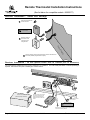
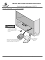
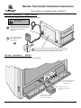
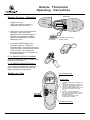
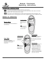
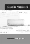
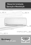
Remote Thermostat Installation Instructions
(See list below for compatible models - 99300677)
CHECK CONDITION OF SHIPMENT
Upon receipt of this kit, check the condition of the packaging. Damage to the package should be noted on the
carrier's freight receipt. Any damage claims as a result of shipping must be handled through the shipper. Travis
Industries will provide assistance in resolving shipping claims or replacing items not included in the package. Please
report any missing items immediately.
COMPATIBILITY
• Avalon Prairie*
• Avalon Salish
• Avalon Cedar*
• Lopi Berkshire*
• Lopi Heritage
• Lopi Allegiance*
• Avalon Hideaway (TV or RV)
• Lopi Sturbridge*
• Tree of Life*
• Lopi Sweet Dreams*
• Spirit DV EF
• FPX 35 CB* (requires the optional receiver heat shield - 220-00020)
• 21 DV Fireplace (TV or RV)
• 864TRV*
• DVL Fireplace EF
* Requires installation of the optional blower
NOTE : This kit is designed as a stand-alone remote. If this remote is replacing a modulating remote, you will need the retrofit
kit (99300 647 or 99300649 depending on model).
ITEMS NEEDED FOR ASSEMBLY
• Three AAA Batteries
PACKING LIST
• Remote Receiver
• Remote Control
• Receiver Mounting Bracket
FCC EQUIPMENT REQUIREMENTS
WARNING: Changes or modifications to this unit not expressly approved by the party responsible for compliance
could void the user's authority to operate the equipment.
N O T E: This equipment has been tested and found to comply with the limits for a Class B digital device, pursuant to
Part 15 of the FCC Rules. These limits are designed to provide reasonable protection against harmful interference in
a residential installation. This equipment generates, uses, and can radiate radio frequency energy and, if not installed
and used in accordance with the instructions, may cause harmful interference to radio communications. However,
there is no guarantee that interference will not occur in a particular installation. If this equipment does cause harmful
interference to radio or television reception, which can be determined by turning the equipment off and on, the user is
encouraged to try to correct the interference by one or more of the following measures:
• Reorient or relocate the receiver.
• Increase the separation between the equipment and receiver.
• Connect the equipment into an outlet on a circuit different from that to which the receiver is connected.
• Consult the dealer or an experienced radio/TV technician for help.
INSTALLATION WARNINGS
!
!
!
!
!
!
Place the remote receiver in the location detailed in these instructions. Placing the receiver in other locations may
cause the receiver to become too hot and degrade and will void the warranty.
All 110 AC wiring must be done by a qualified electrician and shall be in compliance with local codes and the
National Electric Code ANSW/NFPA no. 70 (in the United States).
This kit must be installed by a qualified technician.
Do not connect 110 VAC to the gas control valve, on/off switch, or thermostat posts.
The remote control is carefully engineered and MUST be installed only as specified. It is tested safe when
installed in accordance with this installation manual If you modify it or any of its components, you may possibly
cause a fire hazard. It is your responsibility to read all instructions before starting installation and to follow these
instructions carefully during installation.
Disconnect the power (turn off the household breaker) and shut off the gas supply to the heater before installing
the remote control.
Page 1 of 6
9/28/05
Travis Industries, Inc.
Remote Thermostat Installation Instructions
(See list below for compatible models - 99300677)
Sturbridge Receiver Installation
The optional blower (99000154) must be installed prior to installation
Ashlip
Make sure the power
is disconnected!
a
b
Remove and discard this molex connector.
c
Connect the molex connector to the
connector on the wiring harness.
Place the receiver under the burner on the plate near the gas
control valve.
Receiver Installation - Berkshire, Prairie, Cedar, Tree of Life, and Allegiance
The optional blower (99000153) must be installed prior to installation
Make sure the power
is disconnected!
ve
k
ac
of
Sto
B
a
b
c
Page 2 of 6
Remove and discard this molex
connector.
Attach the molex connector from the
receiver to the connector on the
wiring harness.
Insert the receiver into the mounting bracket. Place the bracket on the
back of the blower mounting plate (magnets hold it in place).
9/28/05
Travis Industries, Inc.
Remote Thermostat Installation Instructions
(See list below for compatible models - 99300677)
Receiver Installation - Salish and Heritage
a
Remove and discard this
molex connector.
Make sure the power
is disconnected!
b
Attach the molex on
the receiver to the
connector on the
wiring harness.
ck
Ba
of
sta
de
Pe
Insert the receiver into the mounting bracket. Place the bracket on the
back of the pedestal (magnets hold it in place).
l
c
Receiver Installation - 35 CB (optional blower must be installed prior to installation)
The optional blower (99000155) and must be installed prior to installation The heat shield (220-00020 - ordered separately) is
required. Remove the face prior to installing the remote receiver.
On
PILOT
IGNITER
Off
c
Receiver Heat Shield
(ordered separately 220-00020)
Place the remote receiver inside
the receiver heat shield. Then
place the heat shield into the
fireplace to the left of the on/off
switch.
a
Remove and discard this
molex connector.
Make sure the power
is disconnected!
b
Attach the molex connector from the receiver to the
connector on the wiring harness.
Page 3 of 6
9/28/05
Travis Industries, Inc.
Remote Thermostat Installation Instructions
(See list below for compatible models - 99300677)
Receiver Installation - 21 DV and Hideaway
Make sure the power
is disconnected!
Pull the molex connector on the
fireplace through the heat shield.
Remove and discard this molex
connector.
Place the receiver into the heat shield (shipped inside
the fireplace). Then slide the heat shield onto the
baseplate of the fireplace on the right side.
Page 4 of 6
9/28/05
Receiver Heat Shield
(shipped inside the
fireplace)
Travis Industries, Inc.
Remote Thermostat Installation Instructions
(See list below for compatible models - 99300677)
Receiver Installation - Sweet Dreams
The optional blower (99000158) must be installed prior to installation
Make sure the power is
disconnected!
a
b
Thread the molex connector on the wiring
harness through this hole near the power
cord (remove the access panel if
necessary).
Remove and discard this
molex connector on the
wiring harness.
c
Attach the molex on the receiver to the connector on the wiring harness.
Insert the receiver into the mounting bracket. Place the bracket on the
back of the stove near the bottom (magnets hold it in place).
Receiver Installation - 864TRV
The optional blower (99000156) must be installed prior to installation
AAAAAAAAAAAAAAAAAAAAAAAAAAAA
AAAAAAAAAAAAAAAAAAAAAAAAAAAA
AAAAAAAAAAAAAAAAAAAAAAAAAAAA
AAAAAAAAAAAAAAAAAAAAAAAAAAAA
AAAAAAAAAAAAAAAAAAAAAAAAAAAA
AAAAAAAAAAAAAAAAAAAAAAAAAAAA
AAAAAAAAAAAAAAAAAAAAAAAAAAAA
AAAAAAAAAAAAAAAAAAAAAAAAAAAA
AAAAAAAAAAAAAAAAAAAAAAAAAAAA
AAAAAAAAAAAAAAAAAAAAAAAAAAAA
AAAAAAAAAAAAAAAAAAAAAAAAAAAA
AAAAAAAAAAAAAAAAAAAAAAAAAAAA
AAAAAAAAAAAAAAAAAAAAAAAAAAAA
AAAAAAAAAAAAAAAAAAAAAAAAAAAA
AAAAAAAAAAAAAAAAAAAAAAAAAAAA
AAAAAAAAAAAAAAAAAAAAAAAAAAAA
AAAAAAAAAAAAAAAAAAAAAAAAAAAA
Remove and discard this molex
connector attached to the
blower wiring harness.
Connect the receiver to the
molex connector on the wiring
harness.
Place the receiver in a location to
the left of the gas control valve
(near the front of the fireplae).
Page 5 of 6
9/28/05
Travis Industries, Inc.
Remote Thermostat Installation Instructions
(See list below for compatible models - 99300677)
Receiver Installation - DVL Fireplace
Make sure the power
is disconnected!
Heat Shield (shipped
inside the fireplace).
a
Remove and discard
this molex connector.
b
Route the molex connector from wiring
harness through the heat shield (shipped
with the fireplace) and connect it to the
connector on the receiver. Place the
remote receiver inside the heat shield.
Remote Calibration
Plug in the heater (or re-set the household breaker) and follow the directions in the operating
instructions to calibrate the remote. Test operation of the remote control.
"Beep"
Receiver
RO
OM
M
A
N
TE
M
P
°F
SE
T
U
TE
MP
°F
A
PM
/ F
L ON O F
:
Fla
He me
igh
t
F
SpFan
eed
A U TO
OF
N/
O
Se
t
CaTi
ncme
el
Page 6 of 6
9/28/05
Travis Industries, Inc.
Remote Thermostat
Operating Instructions
Transmitter
Remote Receiver Calibration
AAA Battery
AAA Battery
Remove the cover from the back of the
transmitter. Insert three "AAA"
batteries into the transmitter as shown.
Slide the code switches to a random
position on the transmitter (if desired).
Replace the cover.
ON DIP
3
AAA Battery
1 2 3 4 5 6
2
Plug in the receiver.
NOTE: each time the remote is recalibrated, unplug the receiver.
C-P
1
Slide the
access
cover off.
ON DIP
1 2 3 4 5 6
Transmitter
Dip Switches
At this point the LED display on the
transmitter will be on. Position the
transmitter within 1 foot of the receiver and
press any button on the transmitter until the
receiver "beeps". This indicates the
transmitter and receiver are calibrated on
the same frequency.
Set these dip switches to a
random position.
"Beep"
Receiver
RO
OM
M
A
N
°F
TE
MP
°F
PM
A
/ F
L ON O F
IF THE REMOTE DOES NOT CALIBRATE:
TE
M
P
SE
T
U
:
Flam
Hei e
ght
F
Fan
Spe
ed
A U TO
OF
N/
O
Remove the batteries, unplug the receiver, and
repeat the process above.
Se
t
CaTim
nc e
el
IF THE REMOTE WORKS ERRATICALLY:
If you suspect interference from a separate
device, repeat the process above, using a
different setting on the dip switches.
Setting the Time
Hour and Minute Display
°F
°F
SET TEMP
TIMER
“CLOCK” Button
ROOM TEMP
ON
MIN
MANUA L
/OFF
ON
TIMER
TO
Fahrenheit or
Celcius Display
ON
/ OFF
CLOCK
AU
1. Press and hold the “CLOCK” button for 2
seconds.
2. The hour display will flash. Use the “Up”
and “Down” arrow buttons to set the hour.
3. Press the “CLOCK” button again.
4. The minute display will flash. Use the “Up”
and “Down” arrow buttons to set the
minute.
5. Press the “CLOCK” button again.
6. The “F” or “C” display will flash. Use the
“Up” and “Down” arrow buttons to select
Fahrenheit or Celsius.
7. Press the “CLOCK” button again.
Programming is complete.
“UP” and “Down” Arrows
Page 1 of 4
9/28/05
Travis Industries, Inc.
Remote Thermostat
Operating Instructions
OPERATING INSTRUCTIONS
NOTE :
This kit must be installed by a qualified technician to work correctly
NOTE :
On gas stoves the pilot flame must be lit, the gas control valve turned to "ON", and the on/off switch
turned to "OFF" for the remote to work correctly.
NOTE : The remote must be calibrated before it will work (see the instructions on the previous page). If the
remote fails to work, try unplugging the remote receiver, plugging it back in, then re-calibrate the remote.
MODES OF OPERATION:
°F
°F
OFF
MIN
MANUA L
/OFF
ON
Use manual mode to turn the heater on
and off directly.
TO TURN ON AND OFF:
Use this key to toggle the
heater on and off. The
display will indicate the
status.
TIMER
CLOCK
ON
/ OF
F
Manual Mode
SET TEMP
TIMER
ROOM TEMP
TO
NOTE:
-- If the room exceeds 90°,
the heater will shut off.
-- If left on, the heater will
shut off after 6 hours.
AU
TO ADJUST TARGET
Auto Mode
Auto mode works like a
thermostat, turning the heater on
and off to meet the desired
temperature.
THERMOSTAT MODE:
Use this key to toggle the
thermostat mode. The
display will indicate
“AUTO” when in
thermostat mode.
TEMPERATURE:
Use the arrow keys to adjust the target
temperature to the desired level.
°F
°F
Auto
MIN
MANUAL
/OFF
ON
9/28/05
TIMER
ON
/ OFF
CLOCK
TO
HINT:
If your heater turns on
and off frequently, adjust
the flame height down
slightly for a more
consistent heat output.
Page 2 of 4
SET TEMP
ROOM TEMP
AU
The heater will turn on and off to keep
the room temperature near the target
temperature.
IMPORTANT NOTES:
-- The thermostat has a delay to prevent
the heater from turning on and off
repeatedly. As a result, the target
temperature may be slightly higher (2°
or 3°) than the room temperature yet
the heater does not turn on – do not
adjust the target temperature – the
heater will turn on in a few minutes.
-- The thermostat is not intended for unattended use. If the thermostat calls for
heat for 6 hours continuously, it will shut
off and not turn on until reset.
Travis Industries, Inc.
Remote Thermostat
Operating Instructions
TIMED OPERATION:
Timed Mode
°F
°F
a) Use the arrow keys to adjust the
target temperature to 90°.
SET TEMP
TIMER
ROOM TEMP
Timed mode allows you to turn
the heater on for a pre-set period
of time.
ON
MIN
b) Press the “TIMER” button - the
“ - - -” will start to flash.
c) Use the arrow keys to set the
number of minutes you would like
the heater to stay on.
MANUA L
/OFF
ON
The heater will turn on and
stay running for the number of
minutes displayed.
TO
ON
/ OFF
TIMER
CLOCK
AU
NOTE:
If the room exceeds 90°, the
heater will shut off.
This is the “Child Proof” Switch
CHILD PROOF FEATURE:
Back of
Transmitter
Child
Proof
Off
The child proof switch allows for the
remote to be “protected” against
undesired use.
To over-ride the
child-proof feature,
press the up and
down buttons in the
following order:
Child
Proof
On
The child proof switch disables
the buttons on the front of the
remote. Thermostat and timed
functions remain operational.
UP
DOWN
ON DIP
C-P
AAA Battery
AAA Battery
The words “Child Proof”
appear here when this features
is turned on.
AAA Battery
1 2 3 4
DOWN
UP
DOWN
Press these buttons
MANUAL
/OFF
ON
TIMER
SET TEMP
TIMER
ON
Page 3 of 4
9/28/05
Slide the
access
cover off.
TO
°F
°F
ROOM TEMP
• Child Proof •
ON
/OF
F
CLOCK
AU
MIN
Travis Industries, Inc.
Remote Thermostat
Operating Instructions
OPERATION WITH DEAD BATTERIES
If the heater is on (any mode) and the batteries go dead, the heater will turn off after 6 hours. To operate the heater,
use the switch on the heater to turn the heater on and off.
OPERATION DURING POWER OUTAGES
If a power outage occurs, the receiver will turn the heater off. Once power is restored, the remote will turn the heater
on (if the remote calls for heat) within 30 minutes.
If you wish to turn the heater on, use the on/off switch on the gas heater to turn the heater on.
Page 4 of 4
9/28/05
Travis Industries, Inc.